EP3145191A1 - Verfahren zur codierung eines lichtfeldinhalts - Google Patents
Verfahren zur codierung eines lichtfeldinhalts Download PDFInfo
- Publication number
- EP3145191A1 EP3145191A1 EP15306437.3A EP15306437A EP3145191A1 EP 3145191 A1 EP3145191 A1 EP 3145191A1 EP 15306437 A EP15306437 A EP 15306437A EP 3145191 A1 EP3145191 A1 EP 3145191A1
- Authority
- EP
- European Patent Office
- Prior art keywords
- light
- ray
- line
- lines
- light field
- Prior art date
- Legal status (The legal status is an assumption and is not a legal conclusion. Google has not performed a legal analysis and makes no representation as to the accuracy of the status listed.)
- Withdrawn
Links
Images


Classifications
-
- H—ELECTRICITY
- H04—ELECTRIC COMMUNICATION TECHNIQUE
- H04N—PICTORIAL COMMUNICATION, e.g. TELEVISION
- H04N19/00—Methods or arrangements for coding, decoding, compressing or decompressing digital video signals
- H04N19/50—Methods or arrangements for coding, decoding, compressing or decompressing digital video signals using predictive coding
- H04N19/597—Methods or arrangements for coding, decoding, compressing or decompressing digital video signals using predictive coding specially adapted for multi-view video sequence encoding
Definitions
- the disclosure relates to the field of computational imaging, light-field acquisition devices, and plenoptic cameras. More precisely, it deals with a representation format for the light-field that can be used for transmission, rendering, processing, mixing of light-field data.
- 4D light-field data enable a user to have access to more post processing features that enhance the rendering of images and/or the interactivity with the user.
- 4D light-field data it is possible to perform with ease refocusing of images a posteriori (i.e. refocusing with freely selected distances of focalization meaning that the position of a focal plane can be specified/selected a posteriori), as well as changing slightly the point of view in the scene of an image.
- a plenoptic camera as depicted in document WO 2013/180192 or in document GB 2488905 , is able to acquire 4D light-field data.
- FIG. 1 and 2 of the present document Details of the architecture of a plenoptic camera are provided in Figures 1 and 2 of the present document.
- Another way to acquire 4D light-field data is to use a camera array as depicted in Figure 3 of the present document. Details of an architecture of a camera array are provided in Figure 3 .
- another way of acquiring a 4D light field is to use a conventional camera that is configured to capture a sequence of 2D images of a same scene at different focal planes.
- the technique described in the document " Light ray field capture using focal plane sweeping and its optical reconstruction using 3D displays" by J.-H. Park et al., published in OPTICS EXPRESS, Vol. 22, No. 21 , in October 2014 can be used to achieve the acquisition of 4D light field data.
- 4D light-field data can be represented, when recorded by a plenoptic camera as the one depicted in Figure 1 for example, by a collection of micro-lens images (see the description of Figure 2 in the present document).
- 4D light-field data in this representation are named raw images (or raw 4D light-field data).
- 4D light-field data can be represented, either when recorded by a plenoptic camera or by a camera array, by a set of sub-aperture images.
- a sub-aperture image corresponds to a captured image of a scene from a point of view, the point of view being slightly different between two sub-aperture images. These sub-aperture images give information about the parallax and depth of the imaged scene.
- 4D light-field data can be represented by a set of epipolar images (see for example the article entitled : " Generating EPI Representation of a 4D Light Fields with a Single Lens Focused Plenoptic Camera", by S. Wanner and al., published in the conference proceedings of ISVC 2011 ).
- plenoptic devices are extremely heterogeneous (for example we can distinguish plenoptic devices of type 1 or 2 (which define particular optical arrangements of the micro-lenses (for example micro-lenses with different focal lengths, etc.))), and that camera arrays come in different flavors, it appears that all these light field acquisition devices have their proprietary file format, so that light-field technology cannot live besides regular 2D or 3D imaging as there is no standard supporting the acquisition and transmission of multi-dimensional information.
- 4D light-field data is represented as raw 4D light-field data
- some additional information such as the size of the micro-lenses, etc. are needed for the processing of the raw 4D light-field data, and for the moment there isn't a standard that list all the needed additional information.
- 4D light-field data as mentioned previously could also be represented by values derived from a parametrization process, as detailed in the paragraph III section A named “Light Field Representation” of the article entitled “ Light Field Analysis for Modeling Image Formation” by Chi-Kai Liang and al., published in the IEEE Transactions on Image Processing, Vol. 20, N°2, in February 2011 , or in the article entitled “ Light Field Rendering” by Mar Levoy and Pat Hanrahan , or in the documents US 8,237,708 , US 6,097,394 or US 6,023,523 .
- 4D light-field data can be represented as a set of points (being associated with light rays) in a coordinate system (see paragraphs [0028] to [0030] of document WO 2013/180192 ). More precisely, the use of a parametrization of a 4D light-field via the use of two planes, either parallel or not, in order to represent 4D light-field data (i.e. each light ray is represented by a set of coordinates values corresponding to the intersection of such light ray with two planes) could be a way to avoid the use of proprietary formats, and to foster the interoperability between 4D light-field devices (i.e.
- plenoptic devices and/or camera arrays for example, but also for 4D light field display devices, such as the one described in the article entitled " Near-Eye Light Field Displays" by D. Lanman and D. Luebke, presented at the conference SIGGRAPH 2013 in July 2013 ).
- a parametrized light field is also named a light slab representation in the previously mentioned article entitled " Light Field Rendering " .
- references in the specification to "one embodiment”, “an embodiment”, “an example embodiment”, indicate that the embodiment described may include a particular feature, structure, or characteristic, but every embodiment may not necessarily include the particular feature, structure, or characteristic. Moreover, such phrases are not necessarily referring to the same embodiment. Further, when a particular feature, structure, or characteristic is described in connection with an embodiment, it is submitted that it is within the knowledge of one skilled in the art to affect such feature, structure, or characteristic in connection with other embodiments whether or not explicitly described.
- the present disclosure is directed to a method for encoding a light field content. Such method is remarkable in that it comprises storing parameters defining a set of lines in a 2D ray diagram, said parameters comprising a set of slope, each line being associated with a slope, and storing for each point belonging to a line in said set of line, a set of points.
- the method further comprises, for at least one line:
- the method is remarkable in that said avoiding further comprises storing an information indicating an occlusion.
- the method is remarkable in that said information is a null value.
- the method is remarkable in that each line of said 2D ray diagram are processed.
- the different steps of the method are implemented by a computer software program or programs, this software program comprising software instructions designed to be executed by a data processor of a relay module according to the disclosure and being designed to control the execution of the different steps of this method.
- an aspect of the disclosure also concerns a program liable to be executed by a computer or by a data processor, this program comprising instructions to command the execution of the steps of a method as mentioned here above.
- This program can use any programming language whatsoever and be in the form of a source code, object code or code that is intermediate between source code and object code, such as in a partially compiled form or in any other desirable form.
- the disclosure also concerns an information medium readable by a data processor and comprising instructions of a program as mentioned here above.
- the information medium can be any entity or device capable of storing the program.
- the medium can comprise a storage means such as a ROM (which stands for "Read Only Memory "), for example a CD-ROM (which stands for “Compact Disc - Read Only Memory ”) or a microelectronic circuit ROM or again a magnetic recording means, for example a floppy disk or a hard disk drive.
- ROM Read Only Memory
- CD-ROM which stands for "Compact Disc - Read Only Memory ”
- microelectronic circuit ROM again a magnetic recording means, for example a floppy disk or a hard disk drive.
- the information medium may be a transmissible carrier such as an electrical or optical signal that can be conveyed through an electrical or optical cable, by radio or by other means.
- the program can be especially downloaded into an Internet-type network.
- the information medium can be an integrated circuit into which the program is incorporated, the circuit being adapted to executing or being used in the execution of the method in question.
- an embodiment of the disclosure is implemented by means of software and/or hardware components.
- module can correspond in this document both to a software component and to a hardware component or to a set of hardware and software components.
- a software component corresponds to one or more computer programs, one or more sub-programs of a program, or more generally to any element of a program or a software program capable of implementing a function or a set of functions according to what is described here below for the module concerned.
- One such software component is executed by a data processor of a physical entity (terminal, server, etc.) and is capable of accessing the hardware resources of this physical entity (memories, recording media, communications buses, input/output electronic boards, user interfaces, etc.).
- a hardware component corresponds to any element of a hardware unit capable of implementing a function or a set of functions according to what is described here below for the module concerned. It may be a programmable hardware component or a component with an integrated circuit for the execution of software, for example an integrated circuit, a smart card, a memory card, an electronic board for executing firmware etc.
- the hardware component comprises a processor that is an integrated circuit such as a central processing unit, and/or a microprocessor, and/or an Application-specific integrated circuit (ASIC), and/or an Application-specific instruction-set processor (ASIP), and/or a graphics processing unit (GPU), and/or a physics processing unit (PPU), and/or a digital signal processor (DSP), and/or an image processor, and/or a coprocessor, and/or a floating-point unit, and/or a network processor, and/or an audio processor, and/or a multi-core processor.
- a processor that is an integrated circuit such as a central processing unit, and/or a microprocessor, and/or an Application-specific integrated circuit (ASIC), and/or an Application-specific instruction-set processor (ASIP), and/or a graphics processing unit (GPU), and/or a physics processing unit (PPU), and/or a digital signal processor (DSP), and/or an image processor, and/or a coprocessor, and
- the hardware component can also comprise a baseband processor (comprising for example memory units, and a firmware) and/or radio electronic circuits (that can comprise antennas) which receive or transmit radio signals.
- the hardware component is compliant with one or more standards such as ISO/IEC 18092 / ECMA-340, ISO/IEC 21481 / ECMA-352, GSMA, StoLPaN, ETSI / SCP (Smart Card Platform), GlobalPlatform (i.e. a secure element).
- the hardware component is a Radio-frequency identification (RFID) tag.
- a hardware component comprises circuits that enable Bluetooth communications, and/or Wi-fi communications, and/or Zigbee communications, and/or USB communications and/or Firewire communications and/or NFC (for Near Field) communications.
- a step of obtaining an element/value in the present document can be viewed either as a step of reading such element/value in a memory unit of an electronic device or a step of receiving such element/value from another electronic device via communication means.
- an electronic device for encoding a light field content the electronic device is remarkable in that it comprises a module configured to store parameters defining a set of lines in a 2D ray diagram, said parameters comprising a set of slope, each line being associated with a slope, and a module configured to store for each point belonging to a line in said set of line, a set of points.
- the electronic device further comprises, for at least one line:
- the electronic device for encoding a light field content is remarkable in that said module configured to avoid, is further configured to store an information indicating an occlusion.
- the electronic device for encoding a light field content is remarkable in that said information is a null value.
- the electronic device for encoding a light field content is remarkable in that each line of said 2D ray diagram are processed.
- Figure 1 present schematically the main components comprised in a plenoptic camera. More precisely, a plenoptic camera comprises a main lens referenced 101, and a sensor array (i.e. an array of pixels)., referenced 104. Between the main lens 101 and the sensor array 104, a microlens array referenced 102, that comprises a set of micro lenses referenced 103, is positioned. It should be noted that optionally some spacers might be located between the micro-lens array around each lens and the sensor to prevent light from one lens to overlap with the light of other lenses at the sensor side.
- a plenoptic camera can be viewed as a conventional camera plus a micro-lens array set just in front of the sensor as illustrated in Figure 1 .
- the light rays passing through a micro-lens cover a part of the sensor array that records the radiance of these light rays. The recording by this part of the sensor defines a micro-lens image.
- Figure 2 present another view of the sensor array 104. Indeed, in such view, it appears that the sensor array 104 comprises a set of pixels, referenced 201. The light rays passing through a micro-lens cover a number of pixels 201, and these pixels record the energy value of light rays that are incident/received.
- the sensor array 104 of a plenoptic camera records an image which comprises a collection of 2D small images (i.e. the micro-lens images referenced 202) arranged within a 2D image (which is also named a raw 4D light-field image).
- each small image i.e. the micro-lens images
- the lens can be identified by coordinates (i,j) from the array of lens.
- the pixels of the light-field are associated with 4 coordinates (x,y,i,j).
- L(x,y,i,j) being the 4D light-field recorded by the sensor illustrates the image which is recorded by the sensor.
- Each micro-lens produces a micro-image represented by a circle (the shape of the small image depends on the shape of the micro-lenses which is typically circular).
- Pixel coordinates in the sensor array
- p is the distance between 2 consecutive micro-images, p is not necessarily an integer value.
- Micro-lenses are chosen such that p is larger than a pixel size ⁇ .
- Micro-lens images are referenced by their coordinate (i, j).
- Each micro-lens image samples the pupil of the main-lens with the (u,v) coordinate system.
- the inter micro-lens space is masked out to prevent photons to pass outside from a micro-lens, resulting in some dark areas in the micro-images. (if the micro-lenses have a square shape, no masking is needed).
- the center of a micro-lens image (i,j) is located on the sensor at the coordinate (x i,j , y i,j ).
- Figure 2 also illustrates that an object from the scene is visible on several contiguous micro-lens images (dark dots). The distance between 2 consecutive views of an object is w, this distance is named the replication distance.
- An object is visible in r 2 micro-lens images. Depending on the shape of the micro-lens image, some of the r 2 views of the object might be invisible.
- 4D light-field data can be represented by sub-aperture images (when the 4D light field data have been acquired by a plenoptic camera of type 1.0 for example).
- Each sub-aperture image is composed of the pixels of same position selected from each microlens image.
- multiview sub-aperture images can be obtained and have different information of incident rays respectively.
- the conventional photograph is equal to the integration of all sub-aperture images, summing all the incident light.
- a 4D light-field image represented by sub-aperture images is defined as being a set (or collection) of m ⁇ n sub-aperture images where each sub-aperture image corresponds to a slightly different perspective of a same scene, and where the parameters m and n are integer greater or equal to one.
- Such 4D light-field image is also named a matrix of view in the state of the art.
- the pixels from the raw sensor image are re-arranged to create an array of images, with the pixels in each coming from the same position under every micro-lens.
- Each sub-aperture image can be thought of as capturing a traditional image of the light passing through only a small sub-aperture region of the camera's lens.
- sub-aperture images provide parallax on the captured scene: foreground objects have relatively higher displacements between adjacent sub-aperture images than background objects.
- the number of pixels positioned below a micro-lens determines the number of sub-aperture images
- the number of micro-lens determines the number of pixels in each sub-aperture images.
- document US2013258098 discloses a pixel that can record light field data due to the use of several light receiving sections (for example referenced 116 and 117 in document US2013258098 ).
- the present disclosure can also be applied to other devices that acquire 4D light field data such as devices that comprise coded aperture elements as depicted in document US 2010/0265386 , or in the article entitled “ Image and depth from a conventional camera with a coded aperture” by A. Levin a al., published in the proceedings of SIGGRAPH 2007 , or use wavefront coding techniques as mentioned in the article entitled “ Extended depth of field through wave-front coding” by Edward R. Dowski, Jr., and W. Thomas Cathe, published in Applied Optics, 1995 Apr 10 .
- FIG. 3 presents in a schematic way a multi-camera array referenced 300.
- the multi-camera array 300 comprises an array of lenses, referenced 301, comprising several lenses referenced 302, and one or several sensor arrays, referenced 304.
- the multi-camera array 300 is without main lens.
- the array of lenses is often a small device, which is commonly named a micro-lens array. It is worth noting that the multi-camera array with a single sensor can be considered as a special case of plenoptic camera where the main lens has an infinite focal. Indeed, a lens with an infinite focal distance has no impact on the rays of light.
- a multi-camera array can be a Pelican array camera as the one depicted in the document WO 2014149403 A1 , or a multi camera array as the one developed by Standford University in the article entitled " High Performance Imaging Using Large Camera Arrays", by B. Wilburn et al., published ACM Transactions on Graphics, Vol 24, No 3, July 2005, pp. 765-776 (Proceedings of ACM SIGGRAPH 2005 ).
- Figure 4 presents how to parametrize a light ray, referenced 401, by the use of two planes, referenced 402 and 403, in 3D space.
- Each plane 402, 403 is defined by two normal vectors (for plane 402, the vectors ( i 1 , j 1 ) defines it, and a 2D coordinates system can be used (i.e. the coordinates system defined by the orthogonal axes (x 1 ) and (y 1 ), and for plane 403, the vectors ( i 2 , j 2 ) defines it and a 2D coordinates system can be used (i.e. the coordinates system defined by the orthogonal axes (x 2 ) and (y 2 )).
- a light field which can be viewed as a collection of light rays in a scene, can be parametrized by a pair of planes, and each light ray of the light field is represented as a point with four coordinates (for example the light ray 401, which has coordinates abcd ⁇ R 4 , and a radiance value L abcd ⁇ R .
- the coordinate of a light ray are noted x 1 y 1 x 2 y 2 ⁇ R 4 (which could be misleading as the terms x 1 ,y 1 ,x 2 ,y 2 also mentioned axis).
- a light ray can also be projected (via an orthographic or orthogonal projection) onto either a plane referenced 404 or a plane referenced 405.
- the plane 404 is a plane which is perpendicular to the two planes 402 and 403, in which y in the 3D Cartesian coordinate space has a constant value.
- the plane 405 is a plane which is perpendicular to the two planes 402 and 403, in which x in the 3D Cartesian coordinate space has a constant value.
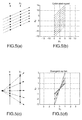
- the result of the projection of some light rays onto plane 404 are depicted in Figures 5(a), 5(c) , 5(e), and 5(g) .
- Figures 5(a) to (h) show two different representations of such 2D slices restricted to the x 1 and x 2 axis.
- Figure 5(a) shows a collimated ray set
- Figure 5(c) presents a divergent ray fan
- Figure 5(e) presents a convergent ray fan
- Figure 5(g) presents a convergent ray fan, focused on the plane 403..
- Figures 5(b), 5(d) , 5(f) and 5(h) present another way of plotting light-field data (i.e. ray lights with their direction) into a 2D ray coordinate system which is maybe easier to handle or create but more difficult to visualize.
- light-field data i.e. ray lights with their direction
- Figure 5(d) presents a diverging beam. Indeed, various degrees of divergence are plotted.
- the markers on the red line represent a set of rays diverging from infinity. Basically, this means that the set is collimated.
- the Figure 5(a) showed already that the line is at 45° and that the relationship between x 1 and x 2 is linear. As the point of divergence is moved from infinity toward the axis x 1 , the 2D ray diagrams is still linear but the steepness of the lines increases with the amount of divergence.
- Figure 5(e) presents a convergent ray set.
- the red marker line is at 45° and represents a beam converging from infinity, which is again a parallel set of rays. It should be noticed that when the point of convergence is pulled toward the x 2 axis, the rays would map on lines of decreasing slopes.
- Figure 5(g) is the limit when the convergence point is on x 2 , a focused rayset, then all rays on the diagram are one the horizontal axis.
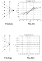
- Figure 6 presents a 2D ray diagram of a random ray fan.
- a uniform random number generator can be used. Then a 2D ray diagram as the basic representation of the light-field and then regenerate in a simple way chosen portions of the light-field from the format.
- Figure 6 shows the corresponding 2D ray-diagram. As expected, there are rays everywhere within ⁇ x 1 ⁇ ⁇ 10 and
- renderings use pinhole cameras to generate images.
- An image is formed on a plane by filtering the light-field by a tiny hole some focal distance in front of that plane (see for example the previously mentioned article entitled:” Understanding camera trade-offs through a Bayesian analysis of light field projections " ).
- rendering images is a matter of "holes". From a ray stand point, this is equivalent to search for convergence or divergence of a set of rays.
- Equation 1 links the pinhole, or the viewpoint (x 3 , z 3 ) to the recorded lightfield parameters (x 1 , z 1 , x 2 , z 2 ) which is the position in the 2D ray-diagram since z 1 and z 2 are known.
- the Figure 7(a) depicts the selection of the light rays in the 2D ray diagram of Figure 6 , according to a selection criteria being ⁇ L 2 D (x 1 , x 2 ) - (x 1 + 5) ⁇ ⁇ 0.1, which enables the selection of parallel set of rays with a direction propagation as shown in Figure 7(b) .
- the Figure 7(b) depicts the reconstructed light field from the selected rays in the 2D ray diagram of Figure 6 .
- the Figure 9 presents a selection of the light rays in Figure 6 with a selection criteria being L 2 D x 1 x 2 ⁇ x 1 / 2 ⁇ 0.1.
- the Figure 10 depicts the rendering of the selected light rays (as selected in Figure 9 ).
- Pinholes are abstract objects, if we want to render the light field by using real lenses models, we need to know the position and the size of the entrance pupil of the lens, and then select in the ray diagram those rays that will trace through the entrance pupil. If the entrance pupil is at (z l ,x l ), and if it has an aperture diameter A with the lens axis parallel to z, then we need to select in the ray diagram all ray points of the ray diagram whose coordinates satisfy equation 1, but with x 3 varying inside x ⁇ - A 2 , x ⁇ + A 2 .
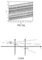
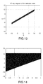
- Figure 15 there are two set of three lines, each group is set at a different depth, because on the 2D ray diagram, different depths result in different slopes.
- this diagram only certain lines are important for the transmission or for the rendering of the light-field, so that there is room for compressing efficiently this representation.
- a natural way of defining which values from the 2D ray-diagram are important is to detect all the lines from the diagram. This can be achieved via the use of Radon transform.
- the Radon transform in two dimensions, named after the Austrian mathematician Johann Radon, is defined as the integral transform consisting of the integral of a function over straight lines.
- Figure 16 is a sinogram, which is the visualization of the Radon transform applied on the2D ray diagram of Figure 15 . We see that it exhibits six local maxima in two groups of three. The first one along the line ⁇ ⁇ 42 and the second along ⁇ ⁇ 27 degrees.
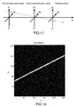
- Figure 17 presents a coordinate system used for general viewpoint rendering in a 3D space.
- Equation 2 basically means that all the rays that do impact (or converge to, or an equivalent formulation would be "form an image") through the point (x 3 ,y 3 ,z 3 ) have their 4 coordinates linked.
- equation 2 defines a hyperplane in (see the article entitled " Polyhedral geometry and the two-plane parameterization", by X. Gu and al., published in Rendering Techniques'97, Proceedings of the Eurographics Workshop in St. Etienne, France, June 16-18, 1997 .
- the light-field is parametrized by two planes
- its representation in the phase space occupies a portion of a 4D space.
- the 4D support of the plenoptic function in that phase space is compact.
- the rays do map along the vicinity of lines. In the 4D case, they map in the vicinity of hyper-planes.
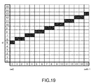
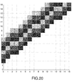
- Figure 20 shows a beam of 6 digital lines according to that definition, with the same s - d value, but different d intercepts. A particular pixel within the region hit by the beam of lines belongs only to one unique line.
- ray data parameterized by a sampled pair of lines (in 2D) and belonging to one camera belong to a of digital lines (beam) in the phase space used for representing the data.
- the header of the beam can simply contain the slope a and the thickness d max - d min of the beam.
- the ray values will be stored as RGB colors along digital lines whose header can be d and s.
- the file will not store void cells of the ray diagram sampled space. Nor will it store the coordinates x 1 , x 2 of the rays, the later will be deduced from d, s and from the position of the cell along the digital line.
- the Figure 21 is a format description that takes into account these remarks, as described later.
- the parameters that need to be estimated from the lightfield or from camera's geometry are the slope a the lower and upper bounds of the digital line intercepts ( d min , dmax ), and then the digital line parameters ( d i , s i ).
- the discrete Radon transform has been discussed as a tool to measure the support location of the light-field in the ray diagram.
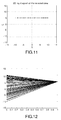
- the Figure 23 shows the discrete Radon transform in the digital line parameter space ( d , s ), which shall not be confused with ( ⁇ , ⁇ ) space of the sinogram.
- Figure 23 shows the discrete Radon transform of the distribution from Figures 18
- Figure 24 is a zoom into the region of interest comprised in Figure 23 .
- the beam of digital lines is spotted by the search for the maximum value parameters.
- finding the maximum without the bias of the content could be done by summing up the number of rays per cell along the integration line, which is more a Hough transform (binary version of Radon).
- the waist of the beam transform as shown on Figure 24 is easy to find and it directly gives the values ( d min , d max ) used into the format.
- variable y 3 * varies between y 3 ⁇ A .
- d off x 1 q , x 2 q , x 3 , y 3 * corresponds to the offset of the lines that need to be scanned and saved for x 1 q , x 2 q .
- the compact light field representation format is defined as follows (see Figure 22(a) ): we first provide the general metadata of the 4D space: boundaries of the 4 axes, and their corresponding sampling. We then provide the number of cameras (bundles). For each camera, we create a block in the table, and we save the following parameters for camera j :
- k is found by determining d max x - d min x 2 A .
- Figure 22(a) is limited to one light slab. However, it can be generalized to the context when six light slabs are used.
- the Figures 22(c) and 22(d) depict an object (the penguin) that could be enclosed into a double box whose sides are used to build light slabs to parameterize the emitted light field capture by some randomly distributed cameras placed outside of the double box/cube.
- the file format of Figure 22(a) can be extended to hold tags for six light slabs. +z has already been assumed previously, but one can add -z, +x, -x, -y, +y to have a complete parametrization of the whole light field.
- Each one of the six orientations gets then assigned a coordinate system for referencing the parametrization planes.
- This direction gets assigned the coordinate system ( e 1 , e 2 , e 3 ) with components ( u,v,w ).
- the planes are set at w 1 and w 2 and their dimensions are u min , u max and v min , v max .
- the 4D ray space will have components within u 1 , u 2 , v 1 , v 2 .
- the Figure 22(b) presents the generalization of the Format in Figure 22(a) .
- the Figure 22(b) presents only two light slab, but in general, depending of the application and on the scene also, there can be any number of section between one and six included.
- the value one would be the format for a light field propagation only in one direction, and the value of six would be for a light field propagation in all directions.
- the planes used to parametrize the light field are not necessary faces of the cube/box, and each one of the plane does not need to have a limitation of its size so as to build up a convex cube.
- Figure 26(a) presents some steps of a method for providing a compact light field representation.
- a light field content is provided to an electronic device.
- Such light field content can be for example 4D light-field data as detailed previously or a two planes parametrization of light rays.
- a parametrization of light rays of the light field content is done via the use of two planes.
- the Figure 26(b) presents a synthetic scheme that depicts a conversion from either 4D light-field data or a conventional 2D image into a representation based on the parametrization of light rays via the use of two planes, corresponding to said step 2000.
- a step referenced 2001 projections of light rays on one plane is done (either on the plane 405 or the plane 404, and generation of one 2D ray diagram is done (i.e. the 2D ray diagram ⁇ (x 1 ,x 2 ) in the case that projection on plane 404 is used, or the 2D ray diagram ⁇ (y 1 ,y 2 ) in the case that projection on plane 405 is used.
- the generation of said one 2D ray diagram can be obtained directly from the sampling of the two parametrization planes.
- the discrete Radon transform is applied on the 2D ray diagram outputted in step 2001 (i.e. the discrete Radon Transform is applied on either ⁇ (x 1 ,x 2 ) or on ⁇ (y 1 ,y 2 ) depending of the output of step 2001) in order to identify some lines of interest in the 2D ray diagram.
- the Bresenham algorithm is used in order to encode the identified lines in the step 2002. It delivers for example for an identified line parameters d and s. In a variant, it only delivers parameters d, and the slope of the identified line. In the case that several identified lines belong to a beam (as explained previously), the slope and the thickness of the beam can be stored.
- a value i.e. an RGB value
- the corresponding ray light does not exist, and a null value is stored. For example, taking the values in Figure 19 , which presents an identified line, then when an electronic have to store the light field content, the value (i.e.
- the Figure 26(b) presents a synthetic scheme that depicts a conversion from either 4D light-field data or a conventional 2D image into a representation based on the parametrization of light rays via the use of two planes.
- a conventional camera i.e. from a conventional 2D image comprising a set of pixels
- a set of light rays that correspond to a rough/average light field representation via a pixel back tracing operation.
- inputted 4D light-field data (obtained via a plenoptic camera or a camera array for example) comprise a set of pixels from which a collection of rays can be extracted.
- the method for converting comprises a pixel back tracing method/operation that can convert a pixel into a light ray.
- a set of sub-aperture images i.e. a set of images from different point of views, taken at a same or close time.
- Each images can be virtually associated with a pixel sensor), therefore by applying a pixel back tracing on each images comprised in the set of sub-aperture images, a ray representation of the 4D light field data can be obtained.
- a parametrization operation is executed by an electronic device.
- Such parametrization operation comprises the use of two planes (obviously, these planes are finite plane) in order to represent a ray as 4 coordinates (i.e. the coordinates of the intersection of a ray with the two planes).
- P is a point in 3D space where a ray launched from pixel ( i , j ).would pass through. So we have one position, P , getting the direction is a matter of evidence, since that ray also passes through (0,0,0), the direction is the vector P ( X , Y , Z ).
- This example illustrates how to back-trace a pixel, or in other words, how to go from pixels to a light-field.
- a multi-camera model can be used (i.e. to each of the sub-aperture images is associated a camera).
- the parameterization is the process of identifying uniquely each ray with some tags. As a ray passes through a position and has a direction, the most straightforward parameterization would be a set of 6 real numbers ( x , y , z , u , v , w ) mixing spatial and directional coordinates. For the sake of simplicity we will adopt here a two plane parameterization already discussed previously. The question which is very often asked is where to put those planes with respect to the acquisition system. Often in the literature, in particular for plenoptic cameras, for some calculation convenience, one is placed at the sensor, another one on the lenslets array or main lens. Those positions should be avoided, because micro-lenses have a thickness, so where exactly shall we put one of the planes? Main lenses have a very complicated lens prescription which is unknown. So in one embodiment, a solution is to put the planes outside of the acquisition system.
- the ray can be uniquely described by the 4-uplet x 1 x 2 y 1 y 2 ⁇ R 4 .
- the ray is assigned with a RGB value. So to represent the ray in this parameterization, we need 4 floats and 3 bytes, a total of 19 bytes (but we have not sampled the ray space so far)!
- the elemental data is represented by 2 floats and 3 bytes only. So we can see that this parameterization adds a lot of data to the content and in general, the light-field being a four dimensional data set, it needs an amount of storage which is not manageable as it is.
- Figure 26 (c) and Figure 26(d) present how a ray is "extracted” from a pixel (or virtual pixel) sensor. Indeed, from a pixel (or virtual pixel) referenced 261 or 264, a chief ray (referenced 262 or 263) can be obtained (being the ray passing through the peak of a cone (the cone being referenced 265)at the pixel location, to the center of the basis of the cone (the base being defined as a function of the size of the main lens of the camera).
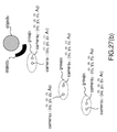
- Figure 27(a) corresponds to a 3D representation of the Figure 17 with some additional elements.
- the pixel pitch is p .
- the pixel array, (also named a pixel sensor) referenced 272 comprising pixels elements, each element having a surface equal to p 2 .
- a birthday cake with candles represents an object in the object space (i.e. a real scene) from which rays are emitted and they go through the center of projection of a camera, also named a camera for simplification, positioned at coordinates ( x 3 , y 3 , z 3 ) in 3D space.
- a camera also named a camera for simplification, positioned at coordinates ( x 3 , y 3 , z 3 ) in 3D space.
- Such camera has an aperture noted A (that is a circle of radius r).
- the two planes ( x 1 , y 1 ) and ( x 2 , y 2 ) are globally chosen outside and common to all cameras that acquire the scene with the birthday cake 277.
- the plane ( x 3 , y 3 ) is positioned on the aperture of each camera.
- the two planes ( x 1 , y 1 ) and ( x 2 , y 2 ) are globally chosen outside and common to all the cameras, and the plane ( x 3 , y 3 ) is positioned on the aperture of each camera), z 1 , z 2 and z 3 are defined to be positive.
- Figure 27(b) presents a scene (comprising two objects) from which images are obtained by the use of cameras. More precisely, the images are obtained from three groups of two cameras.
- a group of camera is defined as a set of camera which are in the same depth plane.
- the first camera is also associated with an aperture value A 1
- the second camera is associated with an aperture value A 2 .
- the third camera is also associated with an aperture value A 3
- the fourth camera is associated with an aperture value A 4 .
- the fifth camera is also associated with an aperture value A 5
- the sixth camera is associated with an aperture value A 6 .
- Figure 27(b) presents a configuration in which some occlusions between the camera occur.
- the fourth camera cannot capture all the rays from the objects in its view field for the scene due to the fact that some rays are blocked by either the first camera or the second camera.
- Figure 27(c) presents a 2D ray diagram of three groups of two cameras.
- the value of the aperture of first camera is greater than the values of other apertures from other cameras.
- Occlusions mentioned previously in the Figure 27(b) can be represented by intersection in a 2D ray diagram.
- the set referenced A in Figure 27(c) corresponds to the set of points that belong to the lines associated with the second camera and the third camera.
- the present technique details a solution for storing the points in the 2D ray diagram (a point being associated with a ray) that correspond to intersection points of two (or more) lines.
- Figure 28 depicts a method for handling the occlusions in a light field content. More precisely, this method takes as input ray lights of a light field represented in two 2D ray diagram ⁇ (x 1 , x 2 ) and ⁇ (y 1 ,y 2 ) as defined previously.
- a step referenced 280 considered as a pre-processing step, the parameters ( m,k ) of each lines identified, by the application of a discrete Radon Transform on the inputted 2D ray diagram ⁇ (x 1 ,x 2 ), are stored on a first set ⁇ 1 . Then, the parameters ( m,k )of each lines identified, by the application of a discrete Radon Transform on the inputted 2D ray diagram ⁇ (y 1 ,y 2 ), are stored on a second set ⁇ 2 .
- the first set ⁇ 1 is sorted according to the parameter m .
- the same method can be applied when processing lines in (y 1 ,y 2 ) i.e. the values of the collection of points for the points (y 1 ,y 2 ) belonging to an intersection area (with a line having a smaller slope) are not stored (or an indicating information of an occlusion is stored).
- Figure 29 presents an example of an electronic device that can be used to perform one or several steps of methods disclosed in the present document.
- Such electronic device referenced 290 comprises a computing unit (for example a CPU, for " Central Processing Unit”), referenced 291, and one or more memory units (for example a RAM (for " Random Access Memory ”) block in which intermediate results can be stored temporarily during the execution of instructions a computer program, or a ROM block in which, among other things, computer programs are stored, or an EEPROM (" Electrically-Erasable Programmable Read-Only Memory ”) block, or a flash block) referenced 292. Computer programs are made of instructions that can be executed by the computing unit.
- Such electronic device 290 can also comprise a dedicated unit, referenced 293, constituting an input-output interface to allow the device 290 to communicate with other electronic devices.
- this dedicated unit 293 can be connected with an antenna (in order to perform communication without contacts), or with serial ports (to carry communications "contact”). It should be noted that the arrows in Figure 29 signify that the linked unit can exchange data through buses for example together.
- some or all of the steps of the method previously described can be implemented in hardware in a programmable FPGA (" Field Programmable Gate Array ”) component or ASIC (" Application-Specific Integrated Circuit ”) component.
- a programmable FPGA Field Programmable Gate Array
- ASIC Application-Specific Integrated Circuit
- some or all of the steps of the method previously described can be executed on an electronic device comprising memory units and processing units as the one disclosed in the Figure 29 .
- the electronic device depicted in Figure 29 can be comprised in a camera device that is configure to capture images (either conventional 2D images or a sampling of a light field). These images are stored on one or more memory units. Hence, these images can be viewed as bit stream data (i.e. a sequence of bits). Obviously, a bit stream can also be converted on byte stream and vice versa.
Landscapes
- Engineering & Computer Science (AREA)
- Multimedia (AREA)
- Signal Processing (AREA)
- Image Processing (AREA)
Priority Applications (10)
| Application Number | Priority Date | Filing Date | Title |
|---|---|---|---|
| EP15306437.3A EP3145191A1 (de) | 2015-09-17 | 2015-09-17 | Verfahren zur codierung eines lichtfeldinhalts |
| CA2998690A CA2998690A1 (en) | 2015-09-17 | 2016-09-15 | Method for encoding a light field content |
| JP2018513441A JP2018537877A (ja) | 2015-09-17 | 2016-09-15 | ライトフィールドコンテンツをエンコードする方法 |
| EP16769942.0A EP3351001B1 (de) | 2015-09-17 | 2016-09-15 | Verfahren zur codierung eines lichtfeldinhalts |
| CN201680065023.8A CN108353188B (zh) | 2015-09-17 | 2016-09-15 | 用于编码光场内容的方法 |
| KR1020187010424A KR20180053724A (ko) | 2015-09-17 | 2016-09-15 | 명시야 콘텐츠를 인코딩하기 위한 방법 |
| US15/761,088 US10880576B2 (en) | 2015-09-17 | 2016-09-15 | Method for encoding a light field content |
| MX2018003263A MX2018003263A (es) | 2015-09-17 | 2016-09-15 | Metodo para codificar un contenido de campo luminoso. |
| RU2018113737A RU2018113737A (ru) | 2015-09-17 | 2016-09-15 | Способ кодирования содержимого светового поля |
| PCT/EP2016/071873 WO2017046272A1 (en) | 2015-09-17 | 2016-09-15 | Method for encoding a light field content |
Applications Claiming Priority (1)
| Application Number | Priority Date | Filing Date | Title |
|---|---|---|---|
| EP15306437.3A EP3145191A1 (de) | 2015-09-17 | 2015-09-17 | Verfahren zur codierung eines lichtfeldinhalts |
Publications (1)
| Publication Number | Publication Date |
|---|---|
| EP3145191A1 true EP3145191A1 (de) | 2017-03-22 |
Family
ID=54252217
Family Applications (1)
| Application Number | Title | Priority Date | Filing Date |
|---|---|---|---|
| EP15306437.3A Withdrawn EP3145191A1 (de) | 2015-09-17 | 2015-09-17 | Verfahren zur codierung eines lichtfeldinhalts |
Country Status (1)
| Country | Link |
|---|---|
| EP (1) | EP3145191A1 (de) |
Cited By (1)
| Publication number | Priority date | Publication date | Assignee | Title |
|---|---|---|---|---|
| CN108596960A (zh) * | 2018-04-12 | 2018-09-28 | 清华大学深圳研究生院 | 一种光场相机的子孔径图像对齐方法 |
Citations (11)
| Publication number | Priority date | Publication date | Assignee | Title |
|---|---|---|---|---|
| US6023523A (en) | 1996-02-16 | 2000-02-08 | Microsoft Corporation | Method and system for digital plenoptic imaging |
| US6097394A (en) | 1997-04-28 | 2000-08-01 | Board Of Trustees, Leland Stanford, Jr. University | Method and system for light field rendering |
| WO2007013194A1 (ja) * | 2005-07-26 | 2007-02-01 | National University Corporation Nagoya University | 画像情報圧縮方法及び自由視点テレビシステム |
| US20100265386A1 (en) | 2007-02-06 | 2010-10-21 | Ramesh Raskar | 4D Light Field Cameras |
| US8237708B2 (en) | 2006-08-18 | 2012-08-07 | William Edward Mantzel | Data structure representing a plenoptic function via compressible layered orthographic projections from multiple orientations |
| GB2488905A (en) | 2011-03-10 | 2012-09-12 | Canon Kk | Image pickup apparatus, such as plenoptic camera, utilizing lens array |
| US20130258098A1 (en) | 2012-03-29 | 2013-10-03 | Canon Kabushiki Kaisha | Imaging apparatus and camera system |
| WO2013180192A1 (en) | 2012-05-31 | 2013-12-05 | Canon Kabushiki Kaisha | Information processing method, information processing apparatus, and program storage medium |
| US20140003732A1 (en) * | 2012-06-28 | 2014-01-02 | Canon Kabushiki Kaisha | Method and apparatus for compressing or decompressing light field images |
| WO2014149403A1 (en) | 2013-03-15 | 2014-09-25 | Pelican Imaging Corporation | Extended color processing on pelican array cameras |
| US20150146032A1 (en) * | 2013-11-22 | 2015-05-28 | Vidinoti Sa | Light field processing method |
-
2015
- 2015-09-17 EP EP15306437.3A patent/EP3145191A1/de not_active Withdrawn
Patent Citations (11)
| Publication number | Priority date | Publication date | Assignee | Title |
|---|---|---|---|---|
| US6023523A (en) | 1996-02-16 | 2000-02-08 | Microsoft Corporation | Method and system for digital plenoptic imaging |
| US6097394A (en) | 1997-04-28 | 2000-08-01 | Board Of Trustees, Leland Stanford, Jr. University | Method and system for light field rendering |
| WO2007013194A1 (ja) * | 2005-07-26 | 2007-02-01 | National University Corporation Nagoya University | 画像情報圧縮方法及び自由視点テレビシステム |
| US8237708B2 (en) | 2006-08-18 | 2012-08-07 | William Edward Mantzel | Data structure representing a plenoptic function via compressible layered orthographic projections from multiple orientations |
| US20100265386A1 (en) | 2007-02-06 | 2010-10-21 | Ramesh Raskar | 4D Light Field Cameras |
| GB2488905A (en) | 2011-03-10 | 2012-09-12 | Canon Kk | Image pickup apparatus, such as plenoptic camera, utilizing lens array |
| US20130258098A1 (en) | 2012-03-29 | 2013-10-03 | Canon Kabushiki Kaisha | Imaging apparatus and camera system |
| WO2013180192A1 (en) | 2012-05-31 | 2013-12-05 | Canon Kabushiki Kaisha | Information processing method, information processing apparatus, and program storage medium |
| US20140003732A1 (en) * | 2012-06-28 | 2014-01-02 | Canon Kabushiki Kaisha | Method and apparatus for compressing or decompressing light field images |
| WO2014149403A1 (en) | 2013-03-15 | 2014-09-25 | Pelican Imaging Corporation | Extended color processing on pelican array cameras |
| US20150146032A1 (en) * | 2013-11-22 | 2015-05-28 | Vidinoti Sa | Light field processing method |
Non-Patent Citations (16)
| Title |
|---|
| A. LEVIN: "Image and depth from a conventional camera with a coded aperture", SIGGRAPH, 2007 |
| ANAT LEVIN: "Understanding camera trade-offs through a Bavesian analysis of light field proiections", CONFERENCE PROCEEDINGS OF ECCV, 2008 |
| B. WILBURN ET AL.: "High Performance Imaging Using Large Camera Arrays", ACM TRANSACTIONS ON GRAPHICS, vol. 24, no. 3, July 2005 (2005-07-01), pages 765 - 776 |
| CHA ZHANG ET AL: "Spectral analysis for sampling image-based rendering data", IEEE TRANSACTIONS ON CIRCUITS AND SYSTEMS FOR VIDEO TECHNOLOGY, IEEE SERVICE CENTER, PISCATAWAY, NJ, US, vol. 13, no. 11, 1 November 2003 (2003-11-01), pages 1038 - 1050, XP011102939, ISSN: 1051-8215, DOI: 10.1109/TCSVT.2003.817350 * |
| CHI-KAI LIANG: "Light Field Analysis for Modeling Image Formation", IEEE TRANSACTIONS ON IMAGE PROCESSING, vol. 20, no. 2, February 2011 (2011-02-01) |
| D. LANMAN; D. LUEBKE: "Near-EVe Light Field Displays", SIGGRAPH 2013, July 2013 (2013-07-01) |
| EDWARD R. DOWSKI, JR.; W. THOMAS CATHE: "Extended depth of field through wave-front coding", APPLIED OPTICS, 10 April 1995 (1995-04-10) |
| EDWARD R; DOWSKI, JR.; W. THOMAS CATHE: "Extended depth of field through wave-front coding", APPLIED OPTICS, 10 April 1995 (1995-04-10) |
| J.-H. PARK ET AL.: "Liaht ray field capture using focal plane sweeping and its optical reconstruction using 3D displays", OPTICS EXPRESS, vol. 22, no. 21, October 2014 (2014-10-01) |
| PROCEEDINGS OF ACM SIGGRAPH, 2005 |
| S. WANNER: "Generatinq EPI Representation of a 4D Light Fields with a Single Lens Focused Plenoptic Camera", ISVC, 2011 |
| TOM E. BISHOP; PAOLO FAVARO: "The Light Field Camera: Extended Depth of Field, Aliasing, and Superresolution", IEEE TRANSACTIONS ON PATTERN ANALYSIS AND MACHINE INTELLIGENCE, vol. 34, no. 5, May 2012 (2012-05-01) |
| W. A. GOTZ; H. J. DRUCKMÜLLER: "A fast d/o/fo radon transform-an efficient means for evaluating the hough transform", PATTERN RECOGN., vol. 28, no. 12, December 1995 (1995-12-01), pages 1985 - 1992 |
| W. H. PRESS: "Discrete Radon transform has an exact, fast inverse and generalizes to operations other than sums along lines", PROC. NATL. ACAD. SCI. USA, vol. 103, no. 51, 2006, pages 19249 - 19254 |
| X. GU: "Polyhedral geometry and the two-plane parameterization", RENDERING TECHNIQUES'97, PROCEEDINGS OF THE EUROGRAPHICS WORKSHOP, 16 June 1997 (1997-06-16) |
| ZHANG C ET AL: "A survey on image-based rendering-representation, sampling and compression", SIGNAL PROCESSING. IMAGE COMMUNICATION, ELSEVIER SCIENCE PUBLISHERS, AMSTERDAM, NL, vol. 19, no. 1, 1 January 2004 (2004-01-01), pages 1 - 28, XP004476835, ISSN: 0923-5965, DOI: 10.1016/J.IMAGE.2003.07.001 * |
Cited By (2)
| Publication number | Priority date | Publication date | Assignee | Title |
|---|---|---|---|---|
| CN108596960A (zh) * | 2018-04-12 | 2018-09-28 | 清华大学深圳研究生院 | 一种光场相机的子孔径图像对齐方法 |
| CN108596960B (zh) * | 2018-04-12 | 2020-09-08 | 清华大学深圳研究生院 | 一种光场相机的子孔径图像对齐方法 |
Similar Documents
| Publication | Publication Date | Title |
|---|---|---|
| US10880576B2 (en) | Method for encoding a light field content | |
| CN107194965B (zh) | 用于处理光场数据的方法和设备 | |
| US10021340B2 (en) | Method and an apparatus for generating data representative of a light field | |
| CN101356546B (zh) | 图像高分辨率化装置、方法及系统 | |
| US10334229B2 (en) | Method for obtaining a refocused image from a 4D raw light field data using a shift correction parameter | |
| CN111563923A (zh) | 获得稠密深度图的方法及相关装置 | |
| US20210329217A1 (en) | Method and an apparatus for generating data representative of a pixel beam | |
| US10762612B2 (en) | Method and an apparatus for generating data representative of a pixel beam | |
| US10909704B2 (en) | Apparatus and a method for generating data representing a pixel beam | |
| EP3145191A1 (de) | Verfahren zur codierung eines lichtfeldinhalts | |
| EP3144886A1 (de) | Verfahren zur codierung eines lichtfeldinhalts | |
| EP3145193A1 (de) | Verfahren zur codierung von lichtfeldinhalt | |
| EP3145194A1 (de) | Verfahren zur codierung von 4d-lichtfelddaten mit diskretisierung einer ersten und einer zweiten ebene in einer lichtfeldparametrierung | |
| EP3145190A1 (de) | Verfahren zur bereitstellung einer bildreihe aus einem lichtfeldinhalt | |
| EP3145192A1 (de) | Verfahren zum anzeigen von 4d-lichtfelddaten | |
| US20190101765A1 (en) | A method and an apparatus for generating data representative of a pixel beam | |
| Ma et al. | Depth from defocus via active multispectral quasi-random point projections using deep learning | |
| Damghanian et al. | The sampling pattern cube–a representation and evaluation tool for optical capturing systems | |
| Aenchbacher | Method for Attaining Object-Side Light Fields and Metric Depth Maps from a Commercial Plenoptic Camera | |
| CN116797641A (zh) | 一种基于稀疏采集的傅里叶全息图生成重建方法 | |
| PARK | Joint Light Field Spatial and Angular Super-Resolution From a Single Image |
Legal Events
| Date | Code | Title | Description |
|---|---|---|---|
| PUAI | Public reference made under article 153(3) epc to a published international application that has entered the european phase |
Free format text: ORIGINAL CODE: 0009012 |
|
| AK | Designated contracting states |
Kind code of ref document: A1 Designated state(s): AL AT BE BG CH CY CZ DE DK EE ES FI FR GB GR HR HU IE IS IT LI LT LU LV MC MK MT NL NO PL PT RO RS SE SI SK SM TR |
|
| AX | Request for extension of the european patent |
Extension state: BA ME |
|
| STAA | Information on the status of an ep patent application or granted ep patent |
Free format text: STATUS: THE APPLICATION IS DEEMED TO BE WITHDRAWN |
|
| 18D | Application deemed to be withdrawn |
Effective date: 20170923 |