EP3145035A1 - Arrangement for establishing an electrical connection between a tab contact and a high current conductor - Google Patents
Arrangement for establishing an electrical connection between a tab contact and a high current conductor Download PDFInfo
- Publication number
- EP3145035A1 EP3145035A1 EP16185486.4A EP16185486A EP3145035A1 EP 3145035 A1 EP3145035 A1 EP 3145035A1 EP 16185486 A EP16185486 A EP 16185486A EP 3145035 A1 EP3145035 A1 EP 3145035A1
- Authority
- EP
- European Patent Office
- Prior art keywords
- high current
- current conductor
- arrangement
- holding structure
- contacting
- Prior art date
- Legal status (The legal status is an assumption and is not a legal conclusion. Google has not performed a legal analysis and makes no representation as to the accuracy of the status listed.)
- Granted
Links
Images

Classifications
-
- H—ELECTRICITY
- H01—ELECTRIC ELEMENTS
- H01R—ELECTRICALLY-CONDUCTIVE CONNECTIONS; STRUCTURAL ASSOCIATIONS OF A PLURALITY OF MUTUALLY-INSULATED ELECTRICAL CONNECTING ELEMENTS; COUPLING DEVICES; CURRENT COLLECTORS
- H01R13/00—Details of coupling devices of the kinds covered by groups H01R12/70 or H01R24/00 - H01R33/00
- H01R13/02—Contact members
- H01R13/15—Pins, blades or sockets having separate spring member for producing or increasing contact pressure
- H01R13/187—Pins, blades or sockets having separate spring member for producing or increasing contact pressure with spring member in the socket
-
- H—ELECTRICITY
- H01—ELECTRIC ELEMENTS
- H01R—ELECTRICALLY-CONDUCTIVE CONNECTIONS; STRUCTURAL ASSOCIATIONS OF A PLURALITY OF MUTUALLY-INSULATED ELECTRICAL CONNECTING ELEMENTS; COUPLING DEVICES; CURRENT COLLECTORS
- H01R13/00—Details of coupling devices of the kinds covered by groups H01R12/70 or H01R24/00 - H01R33/00
- H01R13/02—Contact members
-
- H—ELECTRICITY
- H01—ELECTRIC ELEMENTS
- H01R—ELECTRICALLY-CONDUCTIVE CONNECTIONS; STRUCTURAL ASSOCIATIONS OF A PLURALITY OF MUTUALLY-INSULATED ELECTRICAL CONNECTING ELEMENTS; COUPLING DEVICES; CURRENT COLLECTORS
- H01R13/00—Details of coupling devices of the kinds covered by groups H01R12/70 or H01R24/00 - H01R33/00
- H01R13/02—Contact members
- H01R13/10—Sockets for co-operation with pins or blades
- H01R13/11—Resilient sockets
- H01R13/113—Resilient sockets co-operating with pins or blades having a rectangular transverse section
-
- H—ELECTRICITY
- H01—ELECTRIC ELEMENTS
- H01R—ELECTRICALLY-CONDUCTIVE CONNECTIONS; STRUCTURAL ASSOCIATIONS OF A PLURALITY OF MUTUALLY-INSULATED ELECTRICAL CONNECTING ELEMENTS; COUPLING DEVICES; CURRENT COLLECTORS
- H01R13/00—Details of coupling devices of the kinds covered by groups H01R12/70 or H01R24/00 - H01R33/00
- H01R13/02—Contact members
- H01R13/22—Contacts for co-operating by abutting
-
- H—ELECTRICITY
- H01—ELECTRIC ELEMENTS
- H01R—ELECTRICALLY-CONDUCTIVE CONNECTIONS; STRUCTURAL ASSOCIATIONS OF A PLURALITY OF MUTUALLY-INSULATED ELECTRICAL CONNECTING ELEMENTS; COUPLING DEVICES; CURRENT COLLECTORS
- H01R13/00—Details of coupling devices of the kinds covered by groups H01R12/70 or H01R24/00 - H01R33/00
- H01R13/40—Securing contact members in or to a base or case; Insulating of contact members
- H01R13/42—Securing in a demountable manner
- H01R13/428—Securing in a demountable manner by resilient locking means on the contact members; by locking means on resilient contact members
- H01R13/434—Securing in a demountable manner by resilient locking means on the contact members; by locking means on resilient contact members by separate resilient locking means on contact member, e.g. retainer collar or ring around contact member
-
- H—ELECTRICITY
- H01—ELECTRIC ELEMENTS
- H01R—ELECTRICALLY-CONDUCTIVE CONNECTIONS; STRUCTURAL ASSOCIATIONS OF A PLURALITY OF MUTUALLY-INSULATED ELECTRICAL CONNECTING ELEMENTS; COUPLING DEVICES; CURRENT COLLECTORS
- H01R13/00—Details of coupling devices of the kinds covered by groups H01R12/70 or H01R24/00 - H01R33/00
- H01R13/46—Bases; Cases
-
- H—ELECTRICITY
- H01—ELECTRIC ELEMENTS
- H01R—ELECTRICALLY-CONDUCTIVE CONNECTIONS; STRUCTURAL ASSOCIATIONS OF A PLURALITY OF MUTUALLY-INSULATED ELECTRICAL CONNECTING ELEMENTS; COUPLING DEVICES; CURRENT COLLECTORS
- H01R13/00—Details of coupling devices of the kinds covered by groups H01R12/70 or H01R24/00 - H01R33/00
- H01R13/46—Bases; Cases
- H01R13/50—Bases; Cases formed as an integral body
-
- H—ELECTRICITY
- H01—ELECTRIC ELEMENTS
- H01R—ELECTRICALLY-CONDUCTIVE CONNECTIONS; STRUCTURAL ASSOCIATIONS OF A PLURALITY OF MUTUALLY-INSULATED ELECTRICAL CONNECTING ELEMENTS; COUPLING DEVICES; CURRENT COLLECTORS
- H01R13/00—Details of coupling devices of the kinds covered by groups H01R12/70 or H01R24/00 - H01R33/00
- H01R13/62—Means for facilitating engagement or disengagement of coupling parts or for holding them in engagement
- H01R13/627—Snap or like fastening
- H01R13/6275—Latching arms not integral with the housing
-
- H—ELECTRICITY
- H01—ELECTRIC ELEMENTS
- H01R—ELECTRICALLY-CONDUCTIVE CONNECTIONS; STRUCTURAL ASSOCIATIONS OF A PLURALITY OF MUTUALLY-INSULATED ELECTRICAL CONNECTING ELEMENTS; COUPLING DEVICES; CURRENT COLLECTORS
- H01R4/00—Electrically-conductive connections between two or more conductive members in direct contact, i.e. touching one another; Means for effecting or maintaining such contact; Electrically-conductive connections having two or more spaced connecting locations for conductors and using contact members penetrating insulation
- H01R4/26—Connections in which at least one of the connecting parts has projections which bite into or engage the other connecting part in order to improve the contact
-
- H—ELECTRICITY
- H01—ELECTRIC ELEMENTS
- H01R—ELECTRICALLY-CONDUCTIVE CONNECTIONS; STRUCTURAL ASSOCIATIONS OF A PLURALITY OF MUTUALLY-INSULATED ELECTRICAL CONNECTING ELEMENTS; COUPLING DEVICES; CURRENT COLLECTORS
- H01R4/00—Electrically-conductive connections between two or more conductive members in direct contact, i.e. touching one another; Means for effecting or maintaining such contact; Electrically-conductive connections having two or more spaced connecting locations for conductors and using contact members penetrating insulation
- H01R4/28—Clamped connections, spring connections
-
- H—ELECTRICITY
- H01—ELECTRIC ELEMENTS
- H01R—ELECTRICALLY-CONDUCTIVE CONNECTIONS; STRUCTURAL ASSOCIATIONS OF A PLURALITY OF MUTUALLY-INSULATED ELECTRICAL CONNECTING ELEMENTS; COUPLING DEVICES; CURRENT COLLECTORS
- H01R4/00—Electrically-conductive connections between two or more conductive members in direct contact, i.e. touching one another; Means for effecting or maintaining such contact; Electrically-conductive connections having two or more spaced connecting locations for conductors and using contact members penetrating insulation
- H01R4/28—Clamped connections, spring connections
- H01R4/48—Clamped connections, spring connections utilising a spring, clip, or other resilient member
-
- H—ELECTRICITY
- H01—ELECTRIC ELEMENTS
- H01R—ELECTRICALLY-CONDUCTIVE CONNECTIONS; STRUCTURAL ASSOCIATIONS OF A PLURALITY OF MUTUALLY-INSULATED ELECTRICAL CONNECTING ELEMENTS; COUPLING DEVICES; CURRENT COLLECTORS
- H01R4/00—Electrically-conductive connections between two or more conductive members in direct contact, i.e. touching one another; Means for effecting or maintaining such contact; Electrically-conductive connections having two or more spaced connecting locations for conductors and using contact members penetrating insulation
- H01R4/58—Electrically-conductive connections between two or more conductive members in direct contact, i.e. touching one another; Means for effecting or maintaining such contact; Electrically-conductive connections having two or more spaced connecting locations for conductors and using contact members penetrating insulation characterised by the form or material of the contacting members
Definitions
- the invention relates to an arrangement for establishing an electrical connection between a tab contact and a high current conductor, the arrangement having a holding structure that has a connection section with at least one mounting organ for mounting to a contacting section of the high current conductor and a receptacle for the tab contact.
- the invention relates to a high current conductor, in particular an earthing strap, or a bus bar, with at least one compacted end.
- both the end of the high current conductor to be connected and the tab contact can respectively be provided with an opening through which a screw can be guided so that the tab contact can be screwed to the high current conductor.
- This method can lead to a good electrical connection, but is complex to manage.
- Another known type of connection is one where the high current conductor is initially provided securely with a bushing for the tab contact. The tab contact can then be introduced into the bushing. This allows simple connection, but here too it is laborious to establish and the electrical contact is additionally achieved by means of the bushing. High contact resistances may occur here at a number of points.
- the holding structure has at least one press-on element that is configured to generate a contact pressure in the direction of the connection section.
- the object according to the invention is achieved in that at least one compacted end is connected, by frictional and/or adhesive bond, to a panel-shaped interface member, the interface member having a contacting side pointing away from the compacted end with at least one contacting element at least partially extending away from the interface member.
- the arrangement according to the invention makes it possible to dispense with apparatuses that are laborious to assemble, such as for example screw connections.
- a tab contact can easily be inserted into the receptacle for the latter.
- One can dispense with an opening or a bore hole through the tab contact.
- a tab contact disposed in the receptacle can be pressed against the contacting section of the high current conductor.
- the tab contact can thereby, for example, be pressed directly against the contacting section of the high current conductor.
- the contacting section of the high current conductor can also initially be provided with a panel-shaped interface member which can serve to improve the contact between the tab contact and the contacting section of the high current conductor.
- the at least one press-on element can press the tab contact against the interface member.
- the tab contact is pressed by the press-on element in the direction of the contacting section of the high current conductor disposed in the connection.
- the pressing preferably takes place along a direction of pressing on which runs from the at least one press-on element in the direction of the connection section. In general the pressing direction runs perpendicular to a flat side of a tab contact disposed in the receptacle or perpendicular to a flat side of the contacting section of the high current conductor.
- the contacting section of the high current conductor is preferably made to be at least partially flat or plate-shaped.
- the contacting section of the high current conductor is preferably formed by a compacted end of a braided cable.
- the cable can be an earth cable.
- the end can be compacted, for example, by soldering, resistance welding, crimping, combined crimping and soldering or by ultrasonic welding.
- the contacting section must not necessarily be disposed at the end of the high current conductor. It is also conceivable for the contacting section to be disposed between two conductor ends.
- the high current conductor according to the invention is formed by the panel-shaped interface member such that a tab contact pressed against the latter can establish a good electrical contact with the high current conductor.
- the interface member can be formed such that a good contacting surface for the tab contact is produced.
- the at least one contacting element can also serve to give an improved electrical connection between the high current conductor and the tab contact.
- the at least one press-on element can be formed monolithically with the holding structure and can be deflected elastically away from the receptacle.
- the at least one press-on element can therefore be made like a spring.
- the monolithic configuration it is connected undetachably to the rest of the holding structure.
- the holding structure can thus be easy to produce.
- the elastic deflectability can lead to a tab contact being able to be repeatedly introduced into the receptacle and withdrawn from it again.
- the at least one press-on element can project at least partially into the receptacle.
- the at least one press-on element can be elastically deflected and thus be exposed to spring tension. In this way it can push against the tab contact or press the tab contact in the direction of the connection section or of a contacting section of a high current conductor disposed in the connection section.
- the holding structure has a plurality of press-on elements. In this way a high and even contact pressure onto the tab contact can be generated in the direction of the connection section.
- At least one press-on element can have a substantially elongated form, one end being connected securely to the holding structure so that a freely swinging leaf spring or a spring arm is formed.
- one longitudinal direction of this type of press-on element runs parallel to an insertion direction for a tab contact.
- the tab contact can then slide past the press-on element, by means of which the press-on element is deflected evenly. Since tab contacts are often formed from soft materials due to the good electrical conduction properties that are required, the described arrangement of the at least one press-on element can contribute to protecting the surface of the tab contact.
- the elongate press-on element can project, in particular with its free end, into the receptacle. On this free end the press-on element can be bent away from the receptacle so that a rounded structure is produced which can establish the contact with a tab contact with its rounded side. This can likewise contribute to protecting the surface of a tab contact.
- the holding structure has a plurality of press-on elements with an elongate form which are arranged next to one another transversely to their longitudinal directions and parallel to one another with their longitudinal directions. Respectively adjacent press-on elements can be connected securely to the rest of the holding structure in the opposite direction. In this way an alternating alignment of the press-on elements can be achieved, and this can contribute to particularly even distribution of the contact pressure.
- connection section In order to press a tab contact disposed in the receptacle particularly effectively in the direction of the connection section, in particular against a contacting section of a high current conductor disposed in the connection section, the connection section can lie opposite the at least one press-on element beyond the receptacle for the tab contact.
- the holding structure can have at least one positive locking element for engaging behind the contacting section of the high current conductor. This can serve to securely fix the holding structure to the high current conductor. Furthermore, the at least one positive locking element can serve as a counter-bearing for the high current conductor if at least one press-on element of the holding structure presses a tab contact disposed in the receptacle against the contacting section of the high current conductor.
- the holding structure has a plurality of positive locking elements.
- the at least one positive locking element can be in the form of a latching means that can be deflected away from the connection section. In this way the at least one positive locking element can be released from the high current conductor again in a non-destructive manner.
- the holding structure can be able to be locked to the contacting section of the high current conductor along an assembly direction running substantially parallel to a direction of pressing on the press-on element.
- positive locking elements in the form of latching means can be used for the locking. Due to the possibility of locking, the holding structure can be connected quickly and easily to the high current conductor. Likewise, it may be possible to release the holding structure from the high current conductor again in a non-destructive manner if, for example, the high current conductor of the holding structure is to be replaced.
- the holding structure has latching elements that can be deflected transversely to the assembly direction. In a locked state the latching elements can engage behind the high current conductor.
- the direction of pressing on the at least one press-on element preferably runs transversely to an insertion direction for a tab contact. Consequently, the assembly direction also runs transversely to the insertion direction of the tab contact. In this way it can be guaranteed that upon introducing the tab contact into the receptacle or upon releasing the tab contact from the receptacle, the holding structure will not be separated from the high current conductor.
- a receiving space for the contacting section of the high current conductor can be disposed in the connection section, which receiving space with the receptacle for the tab contact forms a common cavity.
- both the tab contact and the contacting section of the high current conductor can be disposed in this common cavity.
- the receptacle for the tab contact can have an insertion opening which opens at least the receptacle, preferably the common cavity, to the outside in the direction opposite the insertion direction or a plug-in direction for the tab contact.
- at least the receptacle is designed such that it only has an insertion opening for the tab contact and thus predetermines an insertion direction.
- the receptacle and the holding structure can be closed to other directions, and so incorrect insertion of the flat plug or insertion beyond a desired insertion position is prevented.
- the holding structure in the connection section can be at least partially open on its side lying opposite the at least one press-on element.
- the holding structure can have an assembly opening for the insertion of the high current conductor. If the holding structure has a common cavity, as described above, this common cavity is preferably accessible from the outside by means of the assembly opening.
- the holding structure can have at least one clamping element projecting at least partially into the receptacle and that can be deflected elastically from the latter in order to hold a tab contact by frictional bond.
- the clamping element can preferably be deflected transversely to the direction of pressing on.
- the at least one clamping element can rest against the narrow sides of a tab contact disposed in the receptacle in order to secure its position.
- the at least one clamping element can have latching elements which can engage in recesses in the tab contact formed to complement the latter.
- the at least one clamping element can project at least partially into the receptacle, at least if there is no tab contact disposed in the receptacle.
- the at least one clamping element is formed monolithically with the holding structure. It is particularly advantageous if the holding structure has two clamping elements lying opposite over the receptacle so that in an inserted state a tab contact is held between two clamping elements, at least with force closure.
- the holding structure can be made in one piece from steel. In this way the holding structure can be particularly solid and resistant. In this way a good hold on the high current conductor can be guaranteed.
- the at least one press-on element can benefit from the good spring properties of the steel. If it is made of steel, the at least one press-on element can generate a high contact pressure in the direction of the connection section. In this way a tab contact disposed in the receptacle can be pressed with high pressure against the contacting section of the high current conductor.
- the holding structure in particular the at least one press-on element
- the at least one press-on element were in contrast made of a metallic material which was chosen with regard to electrical conductivity, there would be a risk of the at least one press-on element being plastically deformed over time. Materials with a high percentage of copper, for example, tend to creep over time, due to which the contact pressure dwindles. There is also a risk that with frequent deflection of the at least one press-on element, for example due to repeatedly introducing a tab contact into the receptacle, the at least one press-on element will lose its solidity.
- the electrical connection of a tab contact disposed in the receptacle to the high current conductor is essentially established by the direct contact with the contacting section of the high current conductor or with an interface member disposed on the contacting section.
- the electrical conductivity of the holding structure, in particular of the press-on element is therefore not the most important thing.
- the holding structure can also be formed from other materials, in particular materials which have the required spring properties.
- the holding structure can also be formed from other metals or from plastics.
- the arrangement can comprise at least one panel-shaped interface member with a connection side for secure connection to the contacting section of the high current conductor and to a contacting side for the contacting of a tab contact accommodated in the receptacle.
- the contacting section can have a well-defined surface.
- the panel-shaped interface member is preferably formed from a material with good conduction properties.
- the form or surface of the interface member can be made such that the largest possible contact area with a tab contact can be established.
- Another advantage of the interface member is that unevennesses of a compacted end of a high current conductor can be levelled out.
- the at least one panel-shaped interface member can preferably be welded to the contacting section of the high current conductor. By welding the interface member to the high current conductor a secure and highly conductive connection between these parts can be generated. Alternatively or in addition, the panel-shaped interface member can also be connected to the high current conductor by soldering, crimping or riveting. Preferably, the panel-shaped interface member can be secured to the contacting section by laser welding.
- the contacting side can have at least one contacting element at least partially extending away from the interface member.
- the contacting element can be, for example, a projection which points from the contacting side in the direction of the receptacle.
- the contacting element can, for example, be made to be punctiform or rib-like.
- the at least one contacting element is in the form of a contact spring that can be deflected elastically towards the rest of the interface member.
- the at least one contacting element can therefore extend away from the contacting side of the panel-shaped interface member and be able to be deflected elastically towards the latter. This can be advantageous in order to contact a tab contact because, for example, small variations in the distance between the tab contact and the at least one interface member can be evened out.
- the at least one panel-shaped interface member has a plurality of contact springs.
- the contact springs can have, for example, an elongate form and can be arranged with their longitudinal directions parallel to an insertion direction of the tab contact. In this way twisting of the tab contact while being introduced into the receptacle and abrasive wear of the material of the tab contact produced in this way can be avoided.
- the freely moving ends of each contact spring can be bent and/or rounded in order to further protect the surface of a tab contact.
- the contact springs along a row of contact springs arranged next to one another can each have alternating alignments.
- the high current conductor according to the invention can be further improved by the at least one compacted end being provided with an arrangement according to the invention, as described above. It is particularly advantageous if the high current conductor has both a panel-shaped interface member according to the invention and a holding structure according to the invention.
- the high current conductor can have recesses which are formed to complement positive locking elements of a holding structure and can serve to receive these positive locking elements.
- the recesses can be arranged such that the positive locking elements arranged in them prevent movement of the holding structure along the high current conductor in a plane stretching parallel to a flat side of a tab contact.
- the compacted end of the high current conductor is made as a flat part. The recesses can then extend parallel to a plane stretching through and into the flat part.
- the arrangement according to the invention can additionally include a protective housing which surrounds the holding structure according to the invention on a high current conductor according to the invention so that protection against contact is formed for an operator.
- the protective housing according to the invention can in particular be closed so that a VDE test finger cannot establish any contact with conductive parts in the interior of the protective housing.
- the protective housing can be closed to such an extent that there is just a single opening for a tab contact which clears the receptacle for the tab contact in the holding structure to the outside.
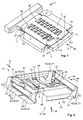
- a high current conductor 1 according to the invention with a panel-shaped interface member 3 according to the invention is described by means of Fig. 1 .
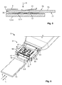
- Fig. 5 shows the high current conductor 1 according to the invention in a sectional illustration.
- the high current conductor 1 has the compacted end 5.
- the compacted end 5 can be formed by resistance welding, ultrasonic welding, crimping, soldering or by other appropriate techniques. Likewise, the end 5 can also be compacted by combining a number of these techniques.
- the compacted end 5 has a substantially flat form which spans the conductor plane 7.
- the compacted end 5 constitutes the contacting section 9 of the high current conductor 1.
- the contacting section 9 as a compacted end 5 of the high current conductor 1 is only given as an example.
- the contacting section 9 can also be disposed in a region of the high current conductor 1 which does not constitute an end of the high current conductor 1.
- the high current conductor 1 is preferably an earthing strap with a compacted end 5 as specified above.
- the high current conductor 1 can also be a bus bar or some other conductor. In the case of a bus bar the part of the latter to be contacted can already be sufficiently compact so that additional compacting is not necessarily required. The end 5 of the bus bar is then compacted per se.
- the high current conductor 1 has recesses 11 which can serve to receive positive locking elements of a holding structure and/or of the interface member 3.
- the compacted end 5 extends substantially along a conduction direction L.
- the recesses 11 preferably extend transversely to the conduction direction L parallel to the conductor plane 7 into the compacted end 5. In this way there can be positive locking with the compacted end 5 at least in conduction direction L if one or more positive locking elements are disposed in one or more of the recesses 11.
- the panel-shaped interface member 3 lies on the contacting section 9 and is connected to the latter, by adhesive bond and/or with form locking.
- the interface member 3 is connected to the high current conductor 1 by laser welding.
- other types of connection are also possible.
- the interface member 3 can be soldered, riveted or crimped to the high current conductor 1. Combinations of these types of connection are also possible.
- the interface member 3 has a contacting side 13 which in the state connected to the high current conductor 1 points away from the compacted end 5.
- the contacting side 13 serves to contact a tab contact.
- the connection side 15 of the interface member 3 is located facing away from the contacting side 13. In the assembled state the connection side 15 lies on the compacted end 5 or the contacting section 9.
- the interface member 3 has a plurality of contacting elements 17.
- the contacting elements 17 are in the form of elastically deflectable contact springs 19. They extend away from the contacting side 13 and can be deflected elastically towards the latter.
- Each of the contact springs 19 has a form which is elongate overall, a longitudinal direction 21 of the contact springs 19 running substantially perpendicular to the conduction direction L.
- the contact springs 19 are at least partially bent back in the direction of the contacting side 13. In this way the free ends 23 are rounded, by means of which the surface of a tab contact, which is connected to the contacting side 13, can be protected.
- the contact springs 19 are arranged in rows running parallel to the conduction direction L.
- contact springs 19 lying next to one another run parallel to one another.
- contact springs 19 lying next to one another have alignments in opposite directions. This means that their free ends 23 each point in opposite directions.
- the interface member 3 has two rows 25 of contact springs 19 running parallel to the conduction direction L and parallel to one another. In this way even covering of the contacting side 13 with contact springs 19 or with contacting elements 17 can be provided.
- the interface member 3 has positive locking elements 27 which can serve to position the interface member 3 on the compacted end 5 in order to secure the position during a fastening process, such as for example welding.
- the positive locking elements 27 are preferably disposed on the outer ends of the interface member 3. They extend away from the contacting side 13 and in the state fitted on the high current conductor 1 are disposed in the recesses 11. In this way displacement of the interface member 3 is effectively prevented both in the conduction direction L and transversely to this within the conductor plane 7.
- Fig. 2 shows a holding structure 29 according to the invention in a perspective illustration.
- the holding structure 29 can constitute an arrangement 31 according to the invention or be part of such an arrangement if the arrangement 31 includes additional components, for example an interface member 3.
- the holding structure 29 is preferably formed in one piece from a steel.
- the holding structure 29 has a connection section 33 for mounting the holding structure 29 to a contacting section 9 of a high current conductor 1 and a receptacle 35 for a tab contact.
- a receiving space 37 for the contacting section 9 of the high current conductor 1 can be disposed in the connection section 33.
- This receiving space 37 preferably forms with the receptacle 35 for the tab contact a common cavity 39.
- the holding structure 29 is preferably open on its side lying opposite the receptacle 35. The assembly opening 40 thus formed can facilitate connection to a high current conductor 1.
- the holding structure 29 has press-on elements 41 which are designed to generate a contact pressure in the direction of the connection section 33. In this way a direction of pressing on A is predetermined. If a high current conductor 1 is disposed in the connection section 33, the direction of pressing on A thus points in the direction of the high current conductor 1. As viewed in the direction of pressing on A, the connection section 33 is disposed behind the receptacle 35. In other words, the connection section 33 lies opposite the press-on elements 41 beyond the receptacle 35. In this way a tab contact disposed in the receptacle 35 can be pressed in the direction of the connection section 33 or onto a high current conductor 1 fixed here.
- the press-on elements 41 are formed monolithically with the holding structure 29 and can be deflected elastically away from the receptacle 35, i.e. they can be deflected away from the receptacle 35 in the direction opposite the direction of pressing on A. At least is there is no tab contact disposed in the receptacle 35 the press-on elements 41 project at least partially into the receptacle 35.
- the press-on elements 41 have an overall elongate form and run substantially transversely to the direction of pressing on A.
- the press-on elements 41 are preferably made in the form of spring arms, one free end 43 being deflectable and one base 45 being connected to the rest of the holding structure 29.
- a plurality of press-on elements 41 are disposed next to one another, the free ends 43 and the bases 45 of adjacent press-on elements 41 respectively alternating.
- the press-on elements 41 therefore have an alternating alignment.
- the longitudinal directions 47 of adjacent press-on elements 41 which are predetermined by a connection line of one respective base 45 to a free end 43, preferably run parallel to one another.
- the press-on elements 41 have curved regions 49 which are orientated with their convex sides towards the receptacle 35. In this way abrasive wear of a surface of a tab contact upon insertion into the receptacle 35 can be avoided.
- the holding structure 29 has an insertion opening 51 which clears the receptacle 35 for a tab contact.
- the receptacle 35 or the holding structure 29 has precisely one insertion opening 51 in order to predetermine a defined insertion direction E for a tab contact.
- the press-on elements 41 preferably run with their longitudinal directions 47 parallel to the insertion direction E.
- the holding structure can have a stop element 53 which can prevent a tab contact from being pushed through beyond a desired position in the receptacle 35. Furthermore, the stop element 53 can prevent a tab contact from being introduced into the holding structure 29 in a direction other than the insertion direction E.
- the holding structure 29 is shaped so that the direction of pressing on A and the insertion direction E run transversely to one another. It is also preferable if the direction of pressing in E and the direction of pressing on A run transversely to the conduction direction L of a high current conductor 1.
- the holding structure preferably respectively has another stop element 55 on both of the opposing ends. These stop elements 55 can also serve to prevent the introduction of a tab contact in a direction deviating from the insertion direction E.
- the stop elements 53 and 55 can additionally or alternatively also serve as spacers or as supports for the holding structure 29 on the contacting section 9. Therefore, with the stop elements 53 and 55 the holding structure 29 can be supported by the high current conductor 1 in the direction of pressing on A.
- the holding structure 29 has clamping elements 57 which flank the receptacle 35 parallel to the insertion direction E.
- the clamping elements 57 project into the receptacle 35 and can be deflected elastically out of the latter.
- the clamping elements 57 are made in the form of spring arms and run substantially parallel to the insertion direction E.
- the clamping elements 57 can be deflected parallel to the conduction direction L or transversely to the insertion direction E and transversely to the direction of pressing on A.
- the clamping elements 57 can serve to hold a tab contact disposed in the receptacle 35 by frictional bond.
- the clamping elements 57 In order to hold a tab contact in the receptacle 35 more securely in the insertion direction E the clamping elements 57 have on free, deflectable ends 59 latching elements 61 which can engage in complementary recesses in a tab contact in order to additionally secure the latter in the insertion direction E.
- the clamping elements 57 with the latching elements 61 then constitute form limits for the tab contact.
- the clamping elements 57 can also serve to guide a tab contact during introduction into the receptacle 35.
- connection section 33 the holding structure 29 has mounting organ 63 which serve to fix the holding structure 29 to the contacting section 9 of the high current conductor 1.
- the mounting organ 63 are preferably made in the form of positive locking elements 65.
- the positive locking elements 65 are designed to engage behind the contacting section 9 of the high current conductor 1. For this purpose they initially run parallel to the direction of pressing on A and then have sections 67 which run transversely to the direction of pressing on A. 2 respective sections 67 which lie opposite one another in the insertion direction E point towards one another here.
- the connection section 33 is delimited in the direction of pressing on A by the sections 67. In a state fitted on the high current conductor 1 the high current conductor 1 or its contacting section 9 can rest against the sections 67.
- the holding structure 29 has two stationary positive locking elements 69 and two positive locking elements 65 which are in the form of elastically deflectable latching means 71.
- the two stationary positive locking elements 69 lie parallel to the insertion direction E here and the two positive locking elements 65 made in the form of latching means 71 also lie parallel to the insertion direction E.
- the latching means 71 can be deflected away from the connection section 33 transversely to the direction of pressing on A. Preferably, the latching means 71 can be deflected away from the connection section 33 parallel to the insertion direction E. By means of the elastic deflectability the sections 67 of the latching means 71 can be deflected away from the connection section 33 so that a high current conductor 1 can be inserted into the connection section 33. In order to insert a high current conductor 1 or in order to place the holding structure 29 on a high current conductor 1 a part of the high current conductor 1 can initially be inserted through the assembly opening 40 into the connection section 33, the fixed positive locking elements 69 engaging behind the latter.
- the part of the holding structure 29 which has the latching means 71 can be pressed against the high current conductor 1 so that the latching means 71 are deflected. In this way the high current conductor 1 can be moved into the connection section 33 and the latching means 71 can return to their initial position shown in Fig. 2 . All of the positive locking elements 65 of the holding structure 29 then engage behind the high current conductor 1. The high current conductor 1 can therefore be moved along an assembly direction M into the holding structure 29 which runs in the direction opposite the direction of pressing on A.
- Fig. 3 shows a holding structure 29 fitted on a contacting section 9 of a high current conductor 1.
- the high current conductor 1 corresponds to the embodiment described with reference to Fig. 1
- the holding structure 29 corresponds to the embodiment described with reference to Fig. 2 .
- the panel-shaped interface member 3 and the holding structure 29 are included in the embodiment of the arrangement 31 according to the invention.
- the holding structure 29 can in particular have been connected to the contacting section 9 in the way described with reference to Fig. 2 .
- the contacting section 9 is disposed in the connection section 33 of the holding structure 29.
- the positive locking elements 65 of the holding structure 29 engage behind the latter.
- the positive locking elements 65 are disposed here in the recesses 11 of the contacting section 9. In this way the holding structure 29 is prevented from becoming detached.
- the press-on elements 41 of the holding structure are disposed lying opposite the contacting elements 17 of the panel-shaped interface member 3 in the direction of pressing on A.
- the stop elements 53 and 55 rest against the high current conductor 1 so that the holding structure 29 is supported on the high current conductor 1 in the direction of pressing on A.
- these serve to prevent a tab contact from being introduced along a direction other than the insertion direction E.
- the receptacle 35 for a tab contact is now exclusively accessible through the insertion opening 51.
- Fig. 4 shows an arrangement 31 according to the invention as shown in Fig. 3 , but with indication of an inserted tab contact 73.
- Fig. 5 shows a cross-section along the section line marked as A-A in Fig. 4 .
- the tab contact 73 is disposed in the receptacle 35.
- the press-on elements 41 lie on its upper side 75 and the contacting elements 17 lie on its lower side 77.
- the press-on elements 41 generate a contact pressure in the direction of the connection section 33 by means of which the tab contact 73 is pressed against the panel-shaped interface member 3 in the direction of pressing on A. In this way an electrical contact is established between the tab contact and the high current conductor 1 via the contacting elements 17 or via the interface member 3.
- the arrangement 31 according to the invention may also consist purely of the holding structure 29.
- the panel-shaped interface member 3 constitutes an improvement of the arrangement 31 according to the invention, but is not necessarily required.
- the insertion direction E runs transversely to the conduction direction L so that this is a 90° plug connection
- the insertion direction E and the conduction direction L in the second embodiment run parallel to one another.
- the embodiment illustrated in Fig. 5 therefore constitutes a 180° plug connection.
- the holding structure 29 has an insertion opening 51 which opens the receptacle 35 in the conduction direction L or in the direction opposite the insertion direction E. Towards the high current conductor 1 the holding structure has a stop element 53. On both of the ends lying transversely to the conduction direction L the holding structure 29 has two further stop elements 55 lying opposite one another.
- the press-on elements 41 are arranged with their longitudinal directions 47 parallel to the insertion direction E so as to also enable trouble-free introduction of a tab contact 73 in the second embodiment.
- the longitudinal directions one and 20 of the contact springs 19 of the panel-shaped interface member 3 are also aligned parallel to the insertion direction E.
Landscapes
- Details Of Connecting Devices For Male And Female Coupling (AREA)
- Connections Effected By Soldering, Adhesion, Or Permanent Deformation (AREA)
- Connection Of Batteries Or Terminals (AREA)
- Coupling Device And Connection With Printed Circuit (AREA)
- Connector Housings Or Holding Contact Members (AREA)
- Connection Or Junction Boxes (AREA)
Abstract
Description
- The invention relates to an arrangement for establishing an electrical connection between a tab contact and a high current conductor, the arrangement having a holding structure that has a connection section with at least one mounting organ for mounting to a contacting section of the high current conductor and a receptacle for the tab contact. Moreover, the invention relates to a high current conductor, in particular an earthing strap, or a bus bar, with at least one compacted end.
- In high current technology, in particular in direct current technology for the automotive industry, it is often necessary to connect a high current conductor, such as for example an earthing strap or a bus bar, to a tab contact, for example a cable lug. Specifically in the automotive industry it is necessary for the connections to be vibration resistant. Since high currents are generally conveyed through the connections, a good electrical contact between the high current conductor and the tab contact is additionally required. Moreover, it is often desirable for this type of connection to be able to be closed and/or released quickly. Arrangements of the aforementioned type are known in the prior art. For example, both the end of the high current conductor to be connected and the tab contact can respectively be provided with an opening through which a screw can be guided so that the tab contact can be screwed to the high current conductor. This method can lead to a good electrical connection, but is complex to manage. Another known type of connection is one where the high current conductor is initially provided securely with a bushing for the tab contact. The tab contact can then be introduced into the bushing. This allows simple connection, but here too it is laborious to establish and the electrical contact is additionally achieved by means of the bushing. High contact resistances may occur here at a number of points.
- It is therefore the object of the invention to provide an arrangement of the type specified above and a high current conductor that guarantee a good electrical contact between the high current conductor and the tab contact in order to convey high currents, allow rapid connection and rapid release of the high current conductor and the tab contact, and can be produced quickly and easily.
- For an arrangement of the type specified above the object according to the invention is achieved in that the holding structure has at least one press-on element that is configured to generate a contact pressure in the direction of the connection section.
- For the high current conductor specified at the start the object according to the invention is achieved in that at least one compacted end is connected, by frictional and/or adhesive bond, to a panel-shaped interface member, the interface member having a contacting side pointing away from the compacted end with at least one contacting element at least partially extending away from the interface member.
- The arrangement according to the invention makes it possible to dispense with apparatuses that are laborious to assemble, such as for example screw connections. For example, a tab contact can easily be inserted into the receptacle for the latter. One can dispense with an opening or a bore hole through the tab contact. By means of the press-on element according to the invention a tab contact disposed in the receptacle can be pressed against the contacting section of the high current conductor. The tab contact can thereby, for example, be pressed directly against the contacting section of the high current conductor. Alternatively, the contacting section of the high current conductor can also initially be provided with a panel-shaped interface member which can serve to improve the contact between the tab contact and the contacting section of the high current conductor. In this case the at least one press-on element can press the tab contact against the interface member. In both of the specified cases the tab contact is pressed by the press-on element in the direction of the contacting section of the high current conductor disposed in the connection. The pressing preferably takes place along a direction of pressing on which runs from the at least one press-on element in the direction of the connection section. In general the pressing direction runs perpendicular to a flat side of a tab contact disposed in the receptacle or perpendicular to a flat side of the contacting section of the high current conductor. The contacting section of the high current conductor is preferably made to be at least partially flat or plate-shaped. The contacting section of the high current conductor is preferably formed by a compacted end of a braided cable. In particular, the cable can be an earth cable. The end can be compacted, for example, by soldering, resistance welding, crimping, combined crimping and soldering or by ultrasonic welding. The contacting section must not necessarily be disposed at the end of the high current conductor. It is also conceivable for the contacting section to be disposed between two conductor ends.
- The high current conductor according to the invention is formed by the panel-shaped interface member such that a tab contact pressed against the latter can establish a good electrical contact with the high current conductor. In particular, the interface member can be formed such that a good contacting surface for the tab contact is produced. The at least one contacting element can also serve to give an improved electrical connection between the high current conductor and the tab contact.
- The solution according to the invention can be further improved by various configurations, each advantageous in their own right, that can be combined with one another in any way. These embodiments and the advantages associated with them will be discussed below.
- According to a first advantageous embodiment of the arrangement according to the invention the at least one press-on element can be formed monolithically with the holding structure and can be deflected elastically away from the receptacle. The at least one press-on element can therefore be made like a spring. By means of the monolithic configuration it is connected undetachably to the rest of the holding structure. In addition, the holding structure can thus be easy to produce. The elastic deflectability can lead to a tab contact being able to be repeatedly introduced into the receptacle and withdrawn from it again.
- At the very least when there is no tab contact positioned in the receptacle of the holding structure the at least one press-on element can project at least partially into the receptacle. Upon introducing a tab contact the at least one press-on element can be elastically deflected and thus be exposed to spring tension. In this way it can push against the tab contact or press the tab contact in the direction of the connection section or of a contacting section of a high current conductor disposed in the connection section.
- Preferably, the holding structure has a plurality of press-on elements. In this way a high and even contact pressure onto the tab contact can be generated in the direction of the connection section.
- At least one press-on element can have a substantially elongated form, one end being connected securely to the holding structure so that a freely swinging leaf spring or a spring arm is formed. Preferably one longitudinal direction of this type of press-on element runs parallel to an insertion direction for a tab contact. Upon introducing the tab contact into the receptacle the tab contact can then slide past the press-on element, by means of which the press-on element is deflected evenly. Since tab contacts are often formed from soft materials due to the good electrical conduction properties that are required, the described arrangement of the at least one press-on element can contribute to protecting the surface of the tab contact.
- The elongate press-on element can project, in particular with its free end, into the receptacle. On this free end the press-on element can be bent away from the receptacle so that a rounded structure is produced which can establish the contact with a tab contact with its rounded side. This can likewise contribute to protecting the surface of a tab contact.
- Preferably, the holding structure has a plurality of press-on elements with an elongate form which are arranged next to one another transversely to their longitudinal directions and parallel to one another with their longitudinal directions. Respectively adjacent press-on elements can be connected securely to the rest of the holding structure in the opposite direction. In this way an alternating alignment of the press-on elements can be achieved, and this can contribute to particularly even distribution of the contact pressure.
- In order to press a tab contact disposed in the receptacle particularly effectively in the direction of the connection section, in particular against a contacting section of a high current conductor disposed in the connection section, the connection section can lie opposite the at least one press-on element beyond the receptacle for the tab contact.
- In the connection section the holding structure can have at least one positive locking element for engaging behind the contacting section of the high current conductor. This can serve to securely fix the holding structure to the high current conductor. Furthermore, the at least one positive locking element can serve as a counter-bearing for the high current conductor if at least one press-on element of the holding structure presses a tab contact disposed in the receptacle against the contacting section of the high current conductor. Preferably, the holding structure has a plurality of positive locking elements.
- In order to achieve engagement behind the contacting section by the at least one positive locking element quickly and easily, the at least one positive locking element can be in the form of a latching means that can be deflected away from the connection section. In this way the at least one positive locking element can be released from the high current conductor again in a non-destructive manner.
- The holding structure can be able to be locked to the contacting section of the high current conductor along an assembly direction running substantially parallel to a direction of pressing on the press-on element. In particular, positive locking elements in the form of latching means can be used for the locking. Due to the possibility of locking, the holding structure can be connected quickly and easily to the high current conductor. Likewise, it may be possible to release the holding structure from the high current conductor again in a non-destructive manner if, for example, the high current conductor of the holding structure is to be replaced.
- Preferably, the holding structure has latching elements that can be deflected transversely to the assembly direction. In a locked state the latching elements can engage behind the high current conductor.
- The direction of pressing on the at least one press-on element preferably runs transversely to an insertion direction for a tab contact. Consequently, the assembly direction also runs transversely to the insertion direction of the tab contact. In this way it can be guaranteed that upon introducing the tab contact into the receptacle or upon releasing the tab contact from the receptacle, the holding structure will not be separated from the high current conductor.
- In order to save on material for the holding structure and also to ensure that a tab contact disposed in the receptacle is pressed without any trouble onto the contacting section of the high current conductor, a receiving space for the contacting section of the high current conductor can be disposed in the connection section, which receiving space with the receptacle for the tab contact forms a common cavity. In a connected state both the tab contact and the contacting section of the high current conductor can be disposed in this common cavity. By means of the common cavity it is possible for the tab contact to be pressed against the high current conductor while the high current conductor is supported on the at least one positive locking element.
- The receptacle for the tab contact can have an insertion opening which opens at least the receptacle, preferably the common cavity, to the outside in the direction opposite the insertion direction or a plug-in direction for the tab contact. Preferably, at least the receptacle is designed such that it only has an insertion opening for the tab contact and thus predetermines an insertion direction. The receptacle and the holding structure can be closed to other directions, and so incorrect insertion of the flat plug or insertion beyond a desired insertion position is prevented.
- In order to facilitate the mounting of the holding structure to the high current conductor or in order to easily insert the high current conductor into the connection section, the holding structure in the connection section can be at least partially open on its side lying opposite the at least one press-on element. In particular, the holding structure can have an assembly opening for the insertion of the high current conductor. If the holding structure has a common cavity, as described above, this common cavity is preferably accessible from the outside by means of the assembly opening.
- The holding structure can have at least one clamping element projecting at least partially into the receptacle and that can be deflected elastically from the latter in order to hold a tab contact by frictional bond. The clamping element can preferably be deflected transversely to the direction of pressing on. In particular, the at least one clamping element can rest against the narrow sides of a tab contact disposed in the receptacle in order to secure its position. At the moveable ends the at least one clamping element can have latching elements which can engage in recesses in the tab contact formed to complement the latter. The at least one clamping element can project at least partially into the receptacle, at least if there is no tab contact disposed in the receptacle. Preferably, the at least one clamping element is formed monolithically with the holding structure. It is particularly advantageous if the holding structure has two clamping elements lying opposite over the receptacle so that in an inserted state a tab contact is held between two clamping elements, at least with force closure.
- According to another advantageous improvement the holding structure can be made in one piece from steel. In this way the holding structure can be particularly solid and resistant. In this way a good hold on the high current conductor can be guaranteed. Another advantage is that the at least one press-on element can benefit from the good spring properties of the steel. If it is made of steel, the at least one press-on element can generate a high contact pressure in the direction of the connection section. In this way a tab contact disposed in the receptacle can be pressed with high pressure against the contacting section of the high current conductor. If the holding structure, in particular the at least one press-on element, were in contrast made of a metallic material which was chosen with regard to electrical conductivity, there would be a risk of the at least one press-on element being plastically deformed over time. Materials with a high percentage of copper, for example, tend to creep over time, due to which the contact pressure dwindles. There is also a risk that with frequent deflection of the at least one press-on element, for example due to repeatedly introducing a tab contact into the receptacle, the at least one press-on element will lose its solidity. In the holding structure according to the invention the electrical connection of a tab contact disposed in the receptacle to the high current conductor is essentially established by the direct contact with the contacting section of the high current conductor or with an interface member disposed on the contacting section. In the arrangement according to the invention the electrical conductivity of the holding structure, in particular of the press-on element, is therefore not the most important thing. Alternatively to the embodiment made of steel, the holding structure can also be formed from other materials, in particular materials which have the required spring properties. For example, the holding structure can also be formed from other metals or from plastics.
- In order to guarantee or further improve the electrical connection between a tab contact disposed in the receptacle and the contacting section of the high current conductor, the arrangement can comprise at least one panel-shaped interface member with a connection side for secure connection to the contacting section of the high current conductor and to a contacting side for the contacting of a tab contact accommodated in the receptacle. In this way it is possible for the contacting section to have a well-defined surface. The panel-shaped interface member is preferably formed from a material with good conduction properties. Likewise, the form or surface of the interface member can be made such that the largest possible contact area with a tab contact can be established. Another advantage of the interface member is that unevennesses of a compacted end of a high current conductor can be levelled out.
- The at least one panel-shaped interface member can preferably be welded to the contacting section of the high current conductor. By welding the interface member to the high current conductor a secure and highly conductive connection between these parts can be generated. Alternatively or in addition, the panel-shaped interface member can also be connected to the high current conductor by soldering, crimping or riveting. Preferably, the panel-shaped interface member can be secured to the contacting section by laser welding.
- In order to further improve the electrical contact between the at least one panel-shaped interface member and a tab contact disposed in the receptacle, the contacting side can have at least one contacting element at least partially extending away from the interface member. The contacting element can be, for example, a projection which points from the contacting side in the direction of the receptacle. The contacting element can, for example, be made to be punctiform or rib-like. In an assembled state, when the panel-shaped interface member is connected to a high current conductor and the holding structure according to the invention is attached to the high current conductor, the at least one contacting element preferably projects at least partially into the receptacle for the tab contact.
- Preferably, the at least one contacting element is in the form of a contact spring that can be deflected elastically towards the rest of the interface member. The at least one contacting element can therefore extend away from the contacting side of the panel-shaped interface member and be able to be deflected elastically towards the latter. This can be advantageous in order to contact a tab contact because, for example, small variations in the distance between the tab contact and the at least one interface member can be evened out.
- Preferably, the at least one panel-shaped interface member has a plurality of contact springs. The contact springs can have, for example, an elongate form and can be arranged with their longitudinal directions parallel to an insertion direction of the tab contact. In this way twisting of the tab contact while being introduced into the receptacle and abrasive wear of the material of the tab contact produced in this way can be avoided. The freely moving ends of each contact spring can be bent and/or rounded in order to further protect the surface of a tab contact. In order to achieve the most even possible contact over the surface of the tab contact, the contact springs along a row of contact springs arranged next to one another can each have alternating alignments.
- The high current conductor according to the invention can be further improved by the at least one compacted end being provided with an arrangement according to the invention, as described above. It is particularly advantageous if the high current conductor has both a panel-shaped interface member according to the invention and a holding structure according to the invention.
- In the region of the compacted end the high current conductor can have recesses which are formed to complement positive locking elements of a holding structure and can serve to receive these positive locking elements. The recesses can be arranged such that the positive locking elements arranged in them prevent movement of the holding structure along the high current conductor in a plane stretching parallel to a flat side of a tab contact. Preferably, the compacted end of the high current conductor is made as a flat part. The recesses can then extend parallel to a plane stretching through and into the flat part.
- The arrangement according to the invention can additionally include a protective housing which surrounds the holding structure according to the invention on a high current conductor according to the invention so that protection against contact is formed for an operator. The protective housing according to the invention can in particular be closed so that a VDE test finger cannot establish any contact with conductive parts in the interior of the protective housing. The protective housing can be closed to such an extent that there is just a single opening for a tab contact which clears the receptacle for the tab contact in the holding structure to the outside.
- In the following the invention will be described in more detail by examples using advantageous embodiments with reference to the drawings. The feature combinations illustrated as examples by the embodiments can be supplemented by additional features for a specific application in accordance with what has been stated above. Individual features may also be omitted in the embodiments described, likewise in accordance with what has been stated above, if the effect of this feature is of no consequence in a specific application.
- In the drawings the same reference signs are always used for elements with the same function and/or the same structure.
- These show as follows:
-
Fig. 1 a high current conductor according to the invention with a panel-shaped interface member in a perspective illustration; -
Fig. 2 a holding structure according to the invention in a perspective illustration looking into a common cavity; -
Fig. 3 the holding structure according to the invention fromFig. 2 in an assembled state on the high current conductor according to the invention fromFig. 1 ; -
Fig. 4 the arrangement according to the invention fromFig. 3 with an inserted tab contact; -
Fig. 5 the arrangement fromFig. 4 in a cross-sectional illustration; -
Fig. 6 a second embodiment of an arrangement according to the invention. - In the following a high
current conductor 1 according to the invention with a panel-shapedinterface member 3 according to the invention is described by means ofFig. 1 . At the same time, reference is made toFig. 5 which shows the highcurrent conductor 1 according to the invention in a sectional illustration. - The high
current conductor 1 has the compacted end 5. The compacted end 5 can be formed by resistance welding, ultrasonic welding, crimping, soldering or by other appropriate techniques. Likewise, the end 5 can also be compacted by combining a number of these techniques. The compacted end 5 has a substantially flat form which spans the conductor plane 7. The compacted end 5 constitutes the contactingsection 9 of the highcurrent conductor 1. The contactingsection 9 as a compacted end 5 of the highcurrent conductor 1 is only given as an example. The contactingsection 9 can also be disposed in a region of the highcurrent conductor 1 which does not constitute an end of the highcurrent conductor 1. The highcurrent conductor 1 is preferably an earthing strap with a compacted end 5 as specified above. Alternatively, the highcurrent conductor 1 can also be a bus bar or some other conductor. In the case of a bus bar the part of the latter to be contacted can already be sufficiently compact so that additional compacting is not necessarily required. The end 5 of the bus bar is then compacted per se. - The high
current conductor 1 hasrecesses 11 which can serve to receive positive locking elements of a holding structure and/or of theinterface member 3. The compacted end 5 extends substantially along a conduction direction L. The recesses 11 preferably extend transversely to the conduction direction L parallel to the conductor plane 7 into the compacted end 5. In this way there can be positive locking with the compacted end 5 at least in conduction direction L if one or more positive locking elements are disposed in one or more of therecesses 11. - The panel-shaped
interface member 3 lies on the contactingsection 9 and is connected to the latter, by adhesive bond and/or with form locking. Preferably, theinterface member 3 is connected to the highcurrent conductor 1 by laser welding. However, other types of connection are also possible. For example, theinterface member 3 can be soldered, riveted or crimped to the highcurrent conductor 1. Combinations of these types of connection are also possible. - The
interface member 3 has a contactingside 13 which in the state connected to the highcurrent conductor 1 points away from the compacted end 5. The contactingside 13 serves to contact a tab contact. Theconnection side 15 of theinterface member 3 is located facing away from the contactingside 13. In the assembled state theconnection side 15 lies on the compacted end 5 or the contactingsection 9. - The
interface member 3 has a plurality of contactingelements 17. The contactingelements 17 are in the form of elastically deflectable contact springs 19. They extend away from the contactingside 13 and can be deflected elastically towards the latter. Each of the contact springs 19 has a form which is elongate overall, alongitudinal direction 21 of the contact springs 19 running substantially perpendicular to the conduction direction L. On their free ends 23 the contact springs 19 are at least partially bent back in the direction of the contactingside 13. In this way the free ends 23 are rounded, by means of which the surface of a tab contact, which is connected to the contactingside 13, can be protected. Preferably, the contact springs 19 are arranged in rows running parallel to the conduction direction L. Here thelongitudinal direction 21 of contact springs 19 lying next to one another run parallel to one another. Preferably, contact springs 19 lying next to one another have alignments in opposite directions. This means that their free ends 23 each point in opposite directions. Preferably, theinterface member 3 has tworows 25 of contact springs 19 running parallel to the conduction direction L and parallel to one another. In this way even covering of the contactingside 13 with contact springs 19 or with contactingelements 17 can be provided. - The
interface member 3 haspositive locking elements 27 which can serve to position theinterface member 3 on the compacted end 5 in order to secure the position during a fastening process, such as for example welding. Thepositive locking elements 27 are preferably disposed on the outer ends of theinterface member 3. They extend away from the contactingside 13 and in the state fitted on the highcurrent conductor 1 are disposed in therecesses 11. In this way displacement of theinterface member 3 is effectively prevented both in the conduction direction L and transversely to this within the conductor plane 7. -
Fig. 2 shows a holdingstructure 29 according to the invention in a perspective illustration. The holdingstructure 29 can constitute anarrangement 31 according to the invention or be part of such an arrangement if thearrangement 31 includes additional components, for example aninterface member 3. - The holding
structure 29 is preferably formed in one piece from a steel. The holdingstructure 29 has aconnection section 33 for mounting the holdingstructure 29 to a contactingsection 9 of a highcurrent conductor 1 and areceptacle 35 for a tab contact. A receiving space 37 for the contactingsection 9 of the highcurrent conductor 1 can be disposed in theconnection section 33. This receiving space 37 preferably forms with thereceptacle 35 for the tab contact a common cavity 39. In theconnection section 33 the holdingstructure 29 is preferably open on its side lying opposite thereceptacle 35. Theassembly opening 40 thus formed can facilitate connection to a highcurrent conductor 1. - The holding
structure 29 has press-onelements 41 which are designed to generate a contact pressure in the direction of theconnection section 33. In this way a direction of pressing on A is predetermined. If a highcurrent conductor 1 is disposed in theconnection section 33, the direction of pressing on A thus points in the direction of the highcurrent conductor 1. As viewed in the direction of pressing on A, theconnection section 33 is disposed behind thereceptacle 35. In other words, theconnection section 33 lies opposite the press-onelements 41 beyond thereceptacle 35. In this way a tab contact disposed in thereceptacle 35 can be pressed in the direction of theconnection section 33 or onto a highcurrent conductor 1 fixed here. - The press-on
elements 41 are formed monolithically with the holdingstructure 29 and can be deflected elastically away from thereceptacle 35, i.e. they can be deflected away from thereceptacle 35 in the direction opposite the direction of pressing on A. At least is there is no tab contact disposed in thereceptacle 35 the press-onelements 41 project at least partially into thereceptacle 35. The press-onelements 41 have an overall elongate form and run substantially transversely to the direction of pressing on A. - The press-on
elements 41 are preferably made in the form of spring arms, onefree end 43 being deflectable and onebase 45 being connected to the rest of the holdingstructure 29. Preferably, a plurality of press-onelements 41 are disposed next to one another, the free ends 43 and thebases 45 of adjacent press-onelements 41 respectively alternating. The press-onelements 41 therefore have an alternating alignment. - The
longitudinal directions 47 of adjacent press-onelements 41, which are predetermined by a connection line of onerespective base 45 to afree end 43, preferably run parallel to one another. The press-onelements 41 havecurved regions 49 which are orientated with their convex sides towards thereceptacle 35. In this way abrasive wear of a surface of a tab contact upon insertion into thereceptacle 35 can be avoided. - The holding
structure 29 has aninsertion opening 51 which clears thereceptacle 35 for a tab contact. Preferably, thereceptacle 35 or the holdingstructure 29 has precisely oneinsertion opening 51 in order to predetermine a defined insertion direction E for a tab contact. The press-onelements 41 preferably run with theirlongitudinal directions 47 parallel to the insertion direction E. - On their end lying opposite the
insertion opening 51 the holding structure can have astop element 53 which can prevent a tab contact from being pushed through beyond a desired position in thereceptacle 35. Furthermore, thestop element 53 can prevent a tab contact from being introduced into the holdingstructure 29 in a direction other than the insertion direction E. - Preferably, the holding
structure 29 is shaped so that the direction of pressing on A and the insertion direction E run transversely to one another. It is also preferable if the direction of pressing in E and the direction of pressing on A run transversely to the conduction direction L of a highcurrent conductor 1. As viewed in the conduction direct L, the holding structure preferably respectively has anotherstop element 55 on both of the opposing ends. These stopelements 55 can also serve to prevent the introduction of a tab contact in a direction deviating from the insertion direction E. The stopelements structure 29 on the contactingsection 9. Therefore, with thestop elements structure 29 can be supported by the highcurrent conductor 1 in the direction of pressing on A. - The holding
structure 29 has clampingelements 57 which flank thereceptacle 35 parallel to the insertion direction E.The clamping elements 57 project into thereceptacle 35 and can be deflected elastically out of the latter. The clampingelements 57 are made in the form of spring arms and run substantially parallel to the insertion direction E. Here the clampingelements 57 can be deflected parallel to the conduction direction L or transversely to the insertion direction E and transversely to the direction of pressing on A. The clampingelements 57 can serve to hold a tab contact disposed in thereceptacle 35 by frictional bond. - In order to hold a tab contact in the
receptacle 35 more securely in the insertion direction E the clampingelements 57 have on free, deflectable ends 59 latching elements 61 which can engage in complementary recesses in a tab contact in order to additionally secure the latter in the insertion direction E.The clamping elements 57 with the latching elements 61 then constitute form limits for the tab contact. In addition to securing a tab contact disposed in thereceptacle 35, the clampingelements 57 can also serve to guide a tab contact during introduction into thereceptacle 35. - In the
connection section 33 the holdingstructure 29 has mounting organ 63 which serve to fix the holdingstructure 29 to the contactingsection 9 of the highcurrent conductor 1. The mounting organ 63 are preferably made in the form ofpositive locking elements 65. Thepositive locking elements 65 are designed to engage behind the contactingsection 9 of the highcurrent conductor 1. For this purpose they initially run parallel to the direction of pressing on A and then havesections 67 which run transversely to the direction of pressing on A. 2respective sections 67 which lie opposite one another in the insertion direction E point towards one another here. Theconnection section 33 is delimited in the direction of pressing on A by thesections 67. In a state fitted on the highcurrent conductor 1 the highcurrent conductor 1 or its contactingsection 9 can rest against thesections 67. If a tab contact is now pressed against a high current conductor disposed in theconnection section 33 by the press-onelements 41, thepositive locking elements 65 serve as counter-bearings for the highcurrent conductor 1. Therefore, the highcurrent conductor 1 is supported against thepositive locking elements 65 and cannot be moved out of the holdingstructure 29 by the contact pressure. In this way a tab contact can be pressed with high pressure against the contactingsection 9. - According to a preferred embodiment the holding
structure 29 has two stationarypositive locking elements 69 and twopositive locking elements 65 which are in the form of elastically deflectable latching means 71. The two stationarypositive locking elements 69 lie parallel to the insertion direction E here and the twopositive locking elements 65 made in the form of latching means 71 also lie parallel to the insertion direction E. - The latching means 71 can be deflected away from the
connection section 33 transversely to the direction of pressing on A. Preferably, the latching means 71 can be deflected away from theconnection section 33 parallel to the insertion direction E. By means of the elastic deflectability thesections 67 of the latching means 71 can be deflected away from theconnection section 33 so that a highcurrent conductor 1 can be inserted into theconnection section 33. In order to insert a highcurrent conductor 1 or in order to place the holdingstructure 29 on a high current conductor 1 a part of the highcurrent conductor 1 can initially be inserted through theassembly opening 40 into theconnection section 33, the fixedpositive locking elements 69 engaging behind the latter. Then the part of the holdingstructure 29 which has the latching means 71 can be pressed against the highcurrent conductor 1 so that the latching means 71 are deflected. In this way the highcurrent conductor 1 can be moved into theconnection section 33 and the latching means 71 can return to their initial position shown inFig. 2 . All of thepositive locking elements 65 of the holdingstructure 29 then engage behind the highcurrent conductor 1. The highcurrent conductor 1 can therefore be moved along an assembly direction M into the holdingstructure 29 which runs in the direction opposite the direction of pressing on A. -
Fig. 3 shows a holdingstructure 29 fitted on a contactingsection 9 of a highcurrent conductor 1. Here the highcurrent conductor 1 corresponds to the embodiment described with reference toFig. 1 and the holdingstructure 29 corresponds to the embodiment described with reference toFig. 2 . In this case the panel-shapedinterface member 3 and the holdingstructure 29 are included in the embodiment of thearrangement 31 according to the invention. The holdingstructure 29 can in particular have been connected to the contactingsection 9 in the way described with reference toFig. 2 . - In the assembled state the contacting
section 9 is disposed in theconnection section 33 of the holdingstructure 29. Thepositive locking elements 65 of the holdingstructure 29 engage behind the latter. Thepositive locking elements 65 are disposed here in therecesses 11 of the contactingsection 9. In this way the holdingstructure 29 is prevented from becoming detached. - The press-on
elements 41 of the holding structure are disposed lying opposite the contactingelements 17 of the panel-shapedinterface member 3 in the direction of pressing on A. Thestop elements current conductor 1 so that the holdingstructure 29 is supported on the highcurrent conductor 1 in the direction of pressing on A. At the same time, as described above, these serve to prevent a tab contact from being introduced along a direction other than the insertion direction E. Thereceptacle 35 for a tab contact is now exclusively accessible through theinsertion opening 51. -
Fig. 4 shows anarrangement 31 according to the invention as shown inFig. 3 , but with indication of an insertedtab contact 73.Fig. 5 shows a cross-section along the section line marked as A-A inFig. 4 . - The
tab contact 73 is disposed in thereceptacle 35. Here the press-onelements 41 lie on itsupper side 75 and the contactingelements 17 lie on itslower side 77. The press-onelements 41 generate a contact pressure in the direction of theconnection section 33 by means of which thetab contact 73 is pressed against the panel-shapedinterface member 3 in the direction of pressing on A. In this way an electrical contact is established between the tab contact and the highcurrent conductor 1 via the contactingelements 17 or via theinterface member 3. It should be noted that thearrangement 31 according to the invention may also consist purely of the holdingstructure 29. The panel-shapedinterface member 3 constitutes an improvement of thearrangement 31 according to the invention, but is not necessarily required. - In the following a second embodiment of the
arrangement 31 according to the invention with a holdingstructure 29 according to the invention on a highcurrent conductor 1 is described with reference toFig. 6 . For the sake of brevity one will only discuss the differences in comparison to the embodiment described with reference toFigs. 1-5 . - While in the first embodiment the insertion direction E runs transversely to the conduction direction L so that this is a 90° plug connection, the insertion direction E and the conduction direction L in the second embodiment run parallel to one another. The embodiment illustrated in
Fig. 5 therefore constitutes a 180° plug connection. - The holding
structure 29 has aninsertion opening 51 which opens thereceptacle 35 in the conduction direction L or in the direction opposite the insertion direction E. Towards the highcurrent conductor 1 the holding structure has astop element 53. On both of the ends lying transversely to the conduction direction L the holdingstructure 29 has twofurther stop elements 55 lying opposite one another. - The press-on
elements 41 are arranged with theirlongitudinal directions 47 parallel to the insertion direction E so as to also enable trouble-free introduction of atab contact 73 in the second embodiment. The longitudinal directions one and 20 of the contact springs 19 of the panel-shapedinterface member 3 are also aligned parallel to the insertion direction E. -
- 1
- high current conductor
- 3
- interface member
- 5
- compacted end
- 7
- conductor plane
- 9
- contacting section
- 11
- recess
- 13
- contacting side
- 15
- connection side
- 17
- contacting element
- 19
- contact spring
- 21
- longitudinal direction of the contact springs
- 23
- free ends of the contact springs
- 25
- row of contact springs
- 27
- positive locking element of the interface member
- 29
- holding structure
- 31
- arrangement
- 33
- connection section
- 35
- receptacle
- 37
- receiving space
- 39
- common cavity
- 40
- assembly opening
- 41
- press-on element
- 43
- free end of a press-on element
- 45
- base of a press-on element
- 47
- longitudinal direction of a press-on element
- 49
- curved region of a press-on element
- 51
- insertion opening
- 53
- stop element
- 55
- additional stop element
- 57
- clamping element
- 59
- deflectable end
- 61
- latching element
- 63
- mounting organ
- 65
- positive locking element
- 67
- section of the positive locking element
- 69
- fixed positive locking element
- 71
- latching means
- 73
- tab contact
- 75
- upper side of the tab contact
- 77
- lower side of the tab contact
- L
- conduction direction
- A
- direction of pressing on
- E
- insertion direction
- M
- assembly direction
Claims (15)
- An arrangement (31) for establishing an electrical connection between a tab contact (73) and a high current conductor (1), the arrangement (31) having a holding structure (29) that has a connection section (33) with at least one mounting organ (63) for mounting to a contacting section (9) of the high current conductor (1) and a receptacle (35) for the tab contact (73), characterised in that the holding structure (29) has at least one press-on element (41) that is configured to generate a contact pressure in the direction of the connection section (33).
- The arrangement (31) according to Claim 1, characterised in that the at least one press-on element (41) is formed monolithically with the holding structure (29) and can be deflected elastically away from the receptacle (35).
- The arrangement (31) according to Claim 1 or 2, characterised in that the connection section (33) lies opposite the at least one press-on element (41) beyond the receptacle (35) for the tab contact (73).
- The arrangement (31) according to any of Claims 1 to 3, characterised in that in the connection section (33) the holding structure (29) has at least one positive locking element (65) for engaging behind the contacting section (9) of the high current conductor (1).
- The arrangement (31) according to Claim 4, characterised in that the at least one positive locking element (65) is made in the form of a latching means (71) that can be deflected away from the connection section (33).
- The arrangement (31) according to Claim 4 or 5, characterised in that the holding structure (29) can be locked to the contacting section (9) of the high current conductor (1) along an assembly direction (M) running substantially parallel to a direction of pressing on (A) the press-on element (41).
- The arrangement (31) according to any of Claims 1 to 6, characterised in that there is disposed in the connection section (33) a receiving space (37) for the contacting section (9) of the high current conductor (1) which forms a common cavity (39) with the receptacle (35) for the tab contact (73).
- The arrangement (31) according to any of Claims 1 to 7, characterised in that the holding structure (29) is at least partially open in the connection section (33) on its side lying opposite the at least one press-on element (41).
- The arrangement (31) according to any of Claims 1 to 8, characterised in that the holding structure (29) has at least one clamping element (57) projecting at least partially into the receptacle (35) and that can be deflected elastically out of the receptacle (35) perpendicular to a direction of pressing on (A) the press-on element (41) in order to hold a tab contact (73) by frictional bond.
- The arrangement (31) according to any of Claims 1 to 9, characterised in that the holding structure (29) is formed in one piece from steel.
- The arrangement (31) according to any of Claims 1 to 10, characterised in that the arrangement (31) comprises at least one panel-shaped interface member (3) with a connection side (15) for secure connection to the contacting section (9) of the high current conductor (1) and to a contacting side (13) for the contacting of a tab contact (73) accommodated in the receptacle (35).
- The arrangement (31) according to Claim 11, characterised in that the contacting side (13) has at least one contacting element (17) extending at least partially away from the interface member (3).
- The arrangement (31) according to Claim 12, characterised in that the at least one contacting element (17) is made in the form of a contact spring (19) that can be deflected elastically towards the rest of the interface member (3).
- A high current conductor (1), in particular an earthing strap, that has at least one compacted end (5), characterised in that the at least one compacted end (5) is connected, by frictional and/or adhesive bond, to a panel-shaped interface member (3), the interface member (3) having a contacting side (13) pointing away from the compacted end (5) with at least one contacting element (17) extending at least partially away from the interface member (3).
- The high current conductor (1) according to Claim 14, characterised in that the at least one compacted end (5) is provided with an arrangement (31) according to any of Claims 1 to 13.
Applications Claiming Priority (1)
| Application Number | Priority Date | Filing Date | Title |
|---|---|---|---|
| DE102015216632.5A DE102015216632A1 (en) | 2015-08-31 | 2015-08-31 | Arrangement for establishing an electrical connection between a flat contact and a high-current conductor |
Publications (2)
| Publication Number | Publication Date |
|---|---|
| EP3145035A1 true EP3145035A1 (en) | 2017-03-22 |
| EP3145035B1 EP3145035B1 (en) | 2020-07-01 |
Family
ID=54697501
Family Applications (2)
| Application Number | Title | Priority Date | Filing Date |
|---|---|---|---|
| EP15195936.8A Not-in-force EP3136516B1 (en) | 2015-08-31 | 2015-11-23 | Connector assembly with a blade connector |
| EP16185486.4A Active EP3145035B1 (en) | 2015-08-31 | 2016-08-24 | Arrangement for establishing an electrical connection between a tab contact and a high current conductor |
Family Applications Before (1)
| Application Number | Title | Priority Date | Filing Date |
|---|---|---|---|
| EP15195936.8A Not-in-force EP3136516B1 (en) | 2015-08-31 | 2015-11-23 | Connector assembly with a blade connector |
Country Status (5)
| Country | Link |
|---|---|
| US (2) | US10218105B2 (en) |
| EP (2) | EP3136516B1 (en) |
| JP (2) | JP6839944B2 (en) |
| CN (2) | CN106486806B (en) |
| DE (1) | DE102015216632A1 (en) |
Cited By (2)
| Publication number | Priority date | Publication date | Assignee | Title |
|---|---|---|---|---|
| US20220368071A1 (en) * | 2021-05-12 | 2022-11-17 | Te Connectivity Germany Gmbh | Vibration-Proof Electrical High-Current Flat Socket Contact Device |
| EP4391241A1 (en) * | 2022-12-20 | 2024-06-26 | Aptiv Technologies AG | High voltage electrical terminal with compliant contact insert |
Families Citing this family (37)
| Publication number | Priority date | Publication date | Assignee | Title |
|---|---|---|---|---|
| DE102015216632A1 (en) * | 2015-08-31 | 2017-03-02 | Te Connectivity Germany Gmbh | Arrangement for establishing an electrical connection between a flat contact and a high-current conductor |
| DE102016209478A1 (en) * | 2016-05-31 | 2017-11-30 | Te Connectivity Germany Gmbh | Connecting cage for connecting two electrical flat contacts |
| DE102016221351A1 (en) * | 2016-10-28 | 2018-05-03 | Te Connectivity Germany Gmbh | Flat contact socket with extension arm |
| DE102016123081B4 (en) * | 2016-11-30 | 2018-06-14 | Amphenol-Tuchel Electronics Gmbh | Cylindrical high current contact connector socket |
| JP6787175B2 (en) * | 2017-02-22 | 2020-11-18 | 株式会社オートネットワーク技術研究所 | Multi-contact terminal |
| DE102017220185A1 (en) | 2017-11-13 | 2019-05-16 | Te Connectivity Germany Gmbh | female contact |
| CN109802258B (en) * | 2017-11-15 | 2022-01-25 | 富士康(昆山)电脑接插件有限公司 | Electric connector and combination thereof |
| JP2019110074A (en) * | 2017-12-20 | 2019-07-04 | 矢崎総業株式会社 | Connection terminal and connector |
| JP2019185885A (en) * | 2018-04-03 | 2019-10-24 | 矢崎総業株式会社 | Relay terminal and relay connector |
| US10181673B1 (en) * | 2018-05-29 | 2019-01-15 | Te Connectivity Corporation | Receptacle terminal for a junction box |
| US10389055B1 (en) * | 2018-06-20 | 2019-08-20 | Delphia Technologies, Llc | Electrical connector assembly |
| FR3094578B1 (en) | 2019-04-01 | 2021-12-10 | Aptiv Tech Ltd | Power connection device for electric heater and connection assembly comprising this device. |
| EP3783744B1 (en) * | 2019-08-23 | 2026-03-25 | Yazaki Europe Ltd. | Electric connection arrangement |
| JP7281087B2 (en) * | 2019-11-01 | 2023-05-25 | 株式会社オートネットワーク技術研究所 | Terminal connection structure |
| CN110957597B (en) * | 2019-12-27 | 2024-08-30 | 深圳乔合里科技股份有限公司 | Double-reed flat high-current terminal and assembling method thereof |
| DE102020001379B3 (en) * | 2020-03-03 | 2021-08-19 | Wieland-Werke Aktiengesellschaft | Arrangement of components for the transmission of electrical current |
| TWI789587B (en) * | 2020-03-31 | 2023-01-11 | 映興電子股份有限公司 | Double knife butt connector |
| EP3896715B1 (en) * | 2020-04-14 | 2024-04-24 | Tyco Electronics France SAS | Fuse holding element configured to releasably cooperate with a conducting bar |
| US11128078B1 (en) * | 2020-07-20 | 2021-09-21 | TE Connectivity Services Gmbh | Current carrying retention clip |
| DE102020121969A1 (en) | 2020-08-21 | 2022-02-24 | Amphenol-Tuchel Electronics Gesellschaft mit beschränkter Haftung | Locking zone for a plug contact element |
| US11264752B1 (en) * | 2020-11-09 | 2022-03-01 | Aptiv Technologies Limited | Planar terminal connector having an additional contact spring |
| JP2022150224A (en) * | 2021-03-26 | 2022-10-07 | 株式会社オートネットワーク技術研究所 | Terminal unit, first terminal, second terminal |
| CN113258372B (en) | 2021-05-26 | 2022-12-02 | 宣城立讯精密工业有限公司 | Electrical connection kit and electrical connector |
| CN113258352B (en) * | 2021-05-26 | 2022-11-29 | 宣城立讯精密工业有限公司 | Electric connection kit and electric connector |
| CN113725663B (en) * | 2021-08-25 | 2022-04-22 | 浙江普可医疗科技有限公司 | Sensor connecting device |
| EP4406068A4 (en) * | 2021-09-22 | 2025-01-01 | Ennovi Industries, Inc. | TILTED COIL COUPLER |
| KR102954731B1 (en) * | 2021-11-18 | 2026-04-21 | 한국단자공업 주식회사 | Connector assembly for electronic components |
| EP4231460A1 (en) * | 2022-02-17 | 2023-08-23 | Tyco Electronics France SAS | Contact element, electrical connector and electrical connector assembly |
| JP2023172374A (en) * | 2022-05-23 | 2023-12-06 | 古河電気工業株式会社 | Female terminals, wires with terminals, female connectors, wires with connectors, and wire harnesses |
| CN118352822A (en) * | 2023-01-13 | 2024-07-16 | 泰科电子(上海)有限公司 | Terminals, Connectors and Connector Assemblies |
| DE102023101116A1 (en) * | 2023-01-18 | 2024-07-18 | Te Connectivity Solutions Gmbh | Vibration-resistant electrical flat socket terminal |
| DE102024126223B3 (en) | 2024-09-12 | 2026-03-12 | Dinkle Electric Machinery (China) Co., Ltd. | PLUG CONNECTOR STRUCTURE |
| CN121886016A (en) * | 2024-10-11 | 2026-04-17 | 泰科电子(上海)有限公司 | Connector terminals, electrical connection assemblies and connectors |
| DE102024210639A1 (en) | 2024-11-06 | 2026-05-07 | Robert Bosch Gesellschaft mit beschränkter Haftung | Electrical cable with plug contour and method for manufacturing a plug contour on an electrical cable |
| DE102024004608A1 (en) | 2024-11-15 | 2026-05-21 | Dinkle Electric Machinery (China) Co., Ltd. | MULTI-CONTACT CONNECTION STRUCTURE |
| DE102024133494A1 (en) * | 2024-11-15 | 2026-05-21 | Dinkle Electric Machinery (China) Co., Ltd. | Multi-contact connection structure and connection plate thereof |
| DE102024004607A1 (en) | 2024-11-15 | 2026-05-21 | Dinkle Electric Machinery (China) Co., Ltd. | MULTI-CONTACT CONNECTION STRUCTURE |
Citations (4)
| Publication number | Priority date | Publication date | Assignee | Title |
|---|---|---|---|---|
| US20030060090A1 (en) * | 2001-09-21 | 2003-03-27 | Allgood Christopher L. | High current automotive electrical connector and terminal |
| DE102007016070A1 (en) * | 2007-04-03 | 2008-10-09 | Lear Corp., Southfield | Electrical connection arrangement and method for using the electrical connection arrangement |
| EP2211425A1 (en) * | 2009-01-23 | 2010-07-28 | MTA S.p.A. | Female electrical terminal |
| EP2720322A1 (en) * | 2011-06-07 | 2014-04-16 | Japan Aviation Electronics Industry, Ltd. | Contact element and connector |
Family Cites Families (60)
| Publication number | Priority date | Publication date | Assignee | Title |
|---|---|---|---|---|
| US2997685A (en) * | 1956-06-05 | 1961-08-22 | Bryant Electric Co | Electrical connector |
| NL135884C (en) * | 1965-11-06 | |||
| DE1665132C3 (en) * | 1967-04-27 | 1975-09-25 | Multi-Contact Ag, Basel (Schweiz) | Electrical contact arrangement, in particular high-current contact arrangement |
| DE3330984A1 (en) * | 1983-08-27 | 1985-03-14 | Licentia Patent-Verwaltungs-Gmbh, 6000 Frankfurt | Device for the electrically conductive connection of two or more electrically conductive pins |
| US5399098A (en) * | 1993-10-29 | 1995-03-21 | Molex Incorporated | Electrical connector and terminal therefor for mating with a blade contact |
| ES2117799T3 (en) * | 1994-07-27 | 1998-08-16 | United Technologies Automotive | ELECTRICAL TERMINAL. |
| DE4433983A1 (en) * | 1994-09-23 | 1996-03-28 | Ackermann Albert Gmbh Co | Terminal block for electrical installations |
| US5588884A (en) * | 1995-09-08 | 1996-12-31 | Packard Hughes Interconnect Company | Stamped and formed contacts for a power connector |
| FR2740266B1 (en) * | 1995-10-20 | 1997-11-28 | Cinch Connecteurs Sa | DEVICE FOR CONNECTING TWO MALE TABS OF ELECTRICAL CONTACTS |
| US5911605A (en) * | 1997-10-16 | 1999-06-15 | Ui Automotive Dearborn, Inc. | Universal terminal connection |
| JPH11307159A (en) * | 1998-04-16 | 1999-11-05 | Kansei Corp | Electrical connection terminal |
| JP3783412B2 (en) * | 1998-06-16 | 2006-06-07 | 住友電装株式会社 | Circuit board |
| JP3736128B2 (en) * | 1998-08-11 | 2006-01-18 | 株式会社日立製作所 | Multicore conductor wire and manufacturing method thereof |
| JP2000243498A (en) * | 1999-02-19 | 2000-09-08 | Furukawa Electric Co Ltd:The | Box type female terminal |
| EP1089387A3 (en) * | 1999-09-27 | 2001-12-19 | F.C.I. - Framatome Connectors International | A modular female electrical terminal |
| CH694478A5 (en) * | 2000-01-20 | 2005-01-31 | Multi Holding Ag | Contact element. |
| US6485337B2 (en) * | 2000-08-30 | 2002-11-26 | Delphi Technologies, Inc. | Electrical connector |
| US6860768B2 (en) * | 2000-09-15 | 2005-03-01 | Alcoa Fujikura Limited | Combination sleeve and spring cage incorporated into a one-piece female terminal for interengaging a corresponding male terminal and method of configuring such a sleeve and spring cage from a blank shape |
| US6264509B1 (en) * | 2001-01-10 | 2001-07-24 | Yazaki North America, Inc. | High cycle terminal with protected failsafe contact |
| FR2830374B1 (en) * | 2001-10-03 | 2004-09-10 | Framatome Connectors Int | CONNECTION DEVICE COMPRISING A DOUBLE CONTACT, PARTICULARLY FOR MEDIUM VOLTAGE APPLICATIONS |
| EP1429424A1 (en) * | 2002-12-10 | 2004-06-16 | Meccanotecnica Codognese S.p.A. | Electric terminal |
| CN2710203Y (en) * | 2003-10-22 | 2005-07-13 | 莫列斯公司 | Card connector assembly |
| DE10351540B3 (en) * | 2003-11-03 | 2005-08-11 | Intedis Gmbh & Co. Kg | Flat plug socket |
| JP2005196975A (en) * | 2003-12-26 | 2005-07-21 | Jst Mfg Co Ltd | connector |
| DE102004015345A1 (en) * | 2004-03-30 | 2005-10-27 | Kostal Kontakt Systeme Gmbh | Electrical socket contact for high current applications |
| CN2755810Y (en) * | 2004-12-14 | 2006-02-01 | 富港电子(东莞)有限公司 | Memory card connector |
| DE102005043601B4 (en) * | 2005-09-12 | 2007-06-14 | Yazaki Europe Ltd., Hemel Hempstead | Contact retaining clip for mounting on a busbar and contact support therefrom |
| US7241180B1 (en) | 2006-01-31 | 2007-07-10 | Medtronic, Inc. | Medical electrical lead connector assembly |
| US7374460B1 (en) * | 2007-04-17 | 2008-05-20 | Traxxas Lp | Electrical connector assembly |
| EP1986272B1 (en) * | 2007-04-26 | 2011-08-10 | Multi-Holding AG | Contact device for providing an electrical contact between flat current carrying line elements |
| EP2048746B1 (en) * | 2007-08-13 | 2016-10-05 | Tyco Electronics Nederland B.V. | Busbar connection system |
| US7766706B2 (en) * | 2008-11-17 | 2010-08-03 | J. S. T. Corporation | Female terminal assembly with compression clip |
| JP5282540B2 (en) * | 2008-11-21 | 2013-09-04 | 日立電線株式会社 | Male-female connection structure |
| JP5173777B2 (en) * | 2008-12-15 | 2013-04-03 | 矢崎総業株式会社 | Male terminal structure |
| US8668531B2 (en) * | 2009-07-03 | 2014-03-11 | Yazaki Corporation | Terminal |
| JP5381492B2 (en) * | 2009-08-19 | 2014-01-08 | 住友電装株式会社 | Female terminal bracket |
| JP2011070897A (en) * | 2009-09-25 | 2011-04-07 | Sumitomo Wiring Syst Ltd | Lever type connector |
| KR101598633B1 (en) * | 2009-11-11 | 2016-02-29 | 타이코에이엠피 주식회사 | Terminal for connector |
| DE202010003555U1 (en) * | 2010-03-16 | 2010-07-08 | Rosenberger Hochfrequenztechnik Gmbh & Co. Kg | High Power Connectors |
| JP2011210429A (en) * | 2010-03-29 | 2011-10-20 | Aisin Aw Co Ltd | Electric connection device |
| CH702863B1 (en) * | 2010-03-30 | 2014-12-15 | Multi Holding Ag | Connecting element. |
| DE202010010827U1 (en) * | 2010-07-29 | 2010-10-21 | Rosenberger Hochfrequenztechnik Gmbh & Co. Kg | High Power Connectors |
| JP5632225B2 (en) * | 2010-07-30 | 2014-11-26 | 矢崎総業株式会社 | Terminal connection structure |
| JP5723694B2 (en) * | 2011-06-21 | 2015-05-27 | 矢崎総業株式会社 | Female terminal |
| JP5723695B2 (en) * | 2011-06-21 | 2015-05-27 | 矢崎総業株式会社 | Female terminal |
| US8388389B2 (en) * | 2011-07-07 | 2013-03-05 | Tyco Electronics Corporation | Electrical connectors having opposing electrical contacts |
| DE102011085700A1 (en) * | 2011-11-03 | 2013-05-08 | Bayerische Motoren Werke Aktiengesellschaft | High current connectors for automotive applications |
| JP2013101795A (en) * | 2011-11-08 | 2013-05-23 | Sumitomo Wiring Syst Ltd | Bus bar connection structure of current detector |
| US8821170B1 (en) * | 2012-07-19 | 2014-09-02 | Robert Hla Thein | Electrical contact having multiple cantilevered beams |
| JP6124074B2 (en) * | 2013-03-21 | 2017-05-10 | 住友電装株式会社 | Female terminal |
| US9070990B2 (en) * | 2013-05-21 | 2015-06-30 | Tyco Electronics Corporation | Power connector having opposing contact springs |
| DE202013103444U1 (en) * | 2013-07-31 | 2014-11-04 | Weidmüller Interface GmbH & Co. KG | Contact element for a plug-in arrangement of a particular externally guided bus system |
| EP3082177B1 (en) * | 2013-12-13 | 2019-02-20 | Hitachi Automotive Systems, Ltd. | Secondary cell module |
| JP6369029B2 (en) * | 2014-01-28 | 2018-08-08 | オムロン株式会社 | connector |
| DE102014001302A1 (en) * | 2014-01-31 | 2014-08-14 | Daimler Ag | Device for fastening electrically conductive cable lug on external electrical contact element, has housing with contact element, and housing non-positively pressing contact portion of conductive cable lug against carrier element |
| CN104037523B (en) * | 2014-06-13 | 2016-05-11 | 四川永贵科技有限公司 | A kind of large current terminal |
| JP6591146B2 (en) * | 2014-07-08 | 2019-10-16 | 日本航空電子工業株式会社 | Contact and connector including the same |
| DE102015216632A1 (en) * | 2015-08-31 | 2017-03-02 | Te Connectivity Germany Gmbh | Arrangement for establishing an electrical connection between a flat contact and a high-current conductor |
| US9893450B2 (en) * | 2015-09-25 | 2018-02-13 | Hirose Electric Co., Ltd. | Electrical connecting member and electrical connector having the same |
| DE102016201103B4 (en) * | 2016-01-26 | 2023-10-05 | Lisa Dräxlmaier GmbH | Contact part |
-
2015
- 2015-08-31 DE DE102015216632.5A patent/DE102015216632A1/en active Pending
- 2015-11-23 EP EP15195936.8A patent/EP3136516B1/en not_active Not-in-force
-
2016
- 2016-08-24 EP EP16185486.4A patent/EP3145035B1/en active Active
- 2016-08-25 JP JP2016164218A patent/JP6839944B2/en not_active Expired - Fee Related
- 2016-08-25 JP JP2016164249A patent/JP6783588B2/en active Active
- 2016-08-30 CN CN201610771189.3A patent/CN106486806B/en not_active Expired - Fee Related
- 2016-08-30 CN CN201610773362.3A patent/CN106486791B/en active Active
- 2016-08-31 US US15/253,282 patent/US10218105B2/en active Active
- 2016-08-31 US US15/253,300 patent/US9793620B2/en not_active Expired - Fee Related
Patent Citations (4)
| Publication number | Priority date | Publication date | Assignee | Title |
|---|---|---|---|---|
| US20030060090A1 (en) * | 2001-09-21 | 2003-03-27 | Allgood Christopher L. | High current automotive electrical connector and terminal |
| DE102007016070A1 (en) * | 2007-04-03 | 2008-10-09 | Lear Corp., Southfield | Electrical connection arrangement and method for using the electrical connection arrangement |
| EP2211425A1 (en) * | 2009-01-23 | 2010-07-28 | MTA S.p.A. | Female electrical terminal |
| EP2720322A1 (en) * | 2011-06-07 | 2014-04-16 | Japan Aviation Electronics Industry, Ltd. | Contact element and connector |
Cited By (3)
| Publication number | Priority date | Publication date | Assignee | Title |
|---|---|---|---|---|
| US20220368071A1 (en) * | 2021-05-12 | 2022-11-17 | Te Connectivity Germany Gmbh | Vibration-Proof Electrical High-Current Flat Socket Contact Device |
| US12431665B2 (en) * | 2021-05-12 | 2025-09-30 | Te Connectivity Germany Gmbh | Vibration-proof electrical high-current flat socket contact device |
| EP4391241A1 (en) * | 2022-12-20 | 2024-06-26 | Aptiv Technologies AG | High voltage electrical terminal with compliant contact insert |
Also Published As
| Publication number | Publication date |
|---|---|
| JP6783588B2 (en) | 2020-11-11 |
| CN106486791A (en) | 2017-03-08 |
| JP2017054808A (en) | 2017-03-16 |
| US9793620B2 (en) | 2017-10-17 |
| JP2017050281A (en) | 2017-03-09 |
| EP3136516A1 (en) | 2017-03-01 |
| EP3136516B1 (en) | 2018-06-20 |
| CN106486806A (en) | 2017-03-08 |
| US20170062966A1 (en) | 2017-03-02 |
| CN106486791B (en) | 2021-09-03 |
| CN106486806B (en) | 2020-02-11 |
| EP3145035B1 (en) | 2020-07-01 |
| US20170062955A1 (en) | 2017-03-02 |
| JP6839944B2 (en) | 2021-03-10 |
| US10218105B2 (en) | 2019-02-26 |
| DE102015216632A1 (en) | 2017-03-02 |
Similar Documents
| Publication | Publication Date | Title |
|---|---|---|
| EP3145035B1 (en) | Arrangement for establishing an electrical connection between a tab contact and a high current conductor | |
| JP7146842B2 (en) | conductor connection terminal | |
| JP6665280B2 (en) | Conductor connection contact element | |
| US9847587B2 (en) | Spring-force terminal connection and plug connector | |
| US9525218B2 (en) | Conductive wire connection structure of rail-type electrical terminal | |
| US7833047B2 (en) | Spring part for retaining electric wires and terminal block comprising said spring part | |
| US10050400B2 (en) | Connection cage for connecting two electrical flat contacts | |
| JP5966041B1 (en) | Branch connector | |
| KR101625293B1 (en) | Electrical connector | |
| KR20050061581A (en) | Connector for flexible flat strip cables | |
| JP2016189329A (en) | Branch connector | |
| CN107810579B (en) | Connection terminal | |
| CN113424369B (en) | Protective conductor joint | |
| US20110312208A1 (en) | Push-in connector for accepting the end of a rigid conductor | |
| CN103208690B (en) | Press-contact connector | |
| KR102748963B1 (en) | Electrical Terminal | |
| EP3324488B1 (en) | Connector arrangement with a conductor press-on member | |
| KR101803796B1 (en) | a cable connecter | |
| KR20160053370A (en) | Electric connector for a power cable | |
| JP7106090B2 (en) | electrical connector | |
| EP2051332B1 (en) | Improved quick wiring connecting terminal | |
| JP2016018716A (en) | Wire holding structure | |
| KR101801439B1 (en) | Insulation displacement connector and insulation displacement connector with wire | |
| KR101728095B1 (en) | Earth terminal | |
| CN120432930A (en) | Retention frames for plug connectors |
Legal Events
| Date | Code | Title | Description |
|---|---|---|---|
| PUAI | Public reference made under article 153(3) epc to a published international application that has entered the european phase |
Free format text: ORIGINAL CODE: 0009012 |
|
| STAA | Information on the status of an ep patent application or granted ep patent |
Free format text: STATUS: THE APPLICATION HAS BEEN PUBLISHED |
|
| AK | Designated contracting states |
Kind code of ref document: A1 Designated state(s): AL AT BE BG CH CY CZ DE DK EE ES FI FR GB GR HR HU IE IS IT LI LT LU LV MC MK MT NL NO PL PT RO RS SE SI SK SM TR |
|
| AX | Request for extension of the european patent |
Extension state: BA ME |
|
| STAA | Information on the status of an ep patent application or granted ep patent |
Free format text: STATUS: REQUEST FOR EXAMINATION WAS MADE |
|
| 17P | Request for examination filed |
Effective date: 20170922 |
|
| RBV | Designated contracting states (corrected) |
Designated state(s): AL AT BE BG CH CY CZ DE DK EE ES FI FR GB GR HR HU IE IS IT LI LT LU LV MC MK MT NL NO PL PT RO RS SE SI SK SM TR |
|
| STAA | Information on the status of an ep patent application or granted ep patent |
Free format text: STATUS: EXAMINATION IS IN PROGRESS |
|
| 17Q | First examination report despatched |
Effective date: 20180319 |
|
| GRAP | Despatch of communication of intention to grant a patent |
Free format text: ORIGINAL CODE: EPIDOSNIGR1 |
|
| STAA | Information on the status of an ep patent application or granted ep patent |
Free format text: STATUS: GRANT OF PATENT IS INTENDED |
|
| INTG | Intention to grant announced |
Effective date: 20200218 |
|
| GRAS | Grant fee paid |
Free format text: ORIGINAL CODE: EPIDOSNIGR3 |
|
| GRAA | (expected) grant |
Free format text: ORIGINAL CODE: 0009210 |
|
| STAA | Information on the status of an ep patent application or granted ep patent |
Free format text: STATUS: THE PATENT HAS BEEN GRANTED |
|
| AK | Designated contracting states |
Kind code of ref document: B1 Designated state(s): AL AT BE BG CH CY CZ DE DK EE ES FI FR GB GR HR HU IE IS IT LI LT LU LV MC MK MT NL NO PL PT RO RS SE SI SK SM TR |
|
| REG | Reference to a national code |
Ref country code: CH Ref legal event code: EP Ref country code: AT Ref legal event code: REF Ref document number: 1287026 Country of ref document: AT Kind code of ref document: T Effective date: 20200715 |
|
| REG | Reference to a national code |
Ref country code: IE Ref legal event code: FG4D |
|
| REG | Reference to a national code |
Ref country code: DE Ref legal event code: R096 Ref document number: 602016039007 Country of ref document: DE |
|
| REG | Reference to a national code |
Ref country code: LT Ref legal event code: MG4D |
|
| PG25 | Lapsed in a contracting state [announced via postgrant information from national office to epo] |
Ref country code: BG Free format text: LAPSE BECAUSE OF FAILURE TO SUBMIT A TRANSLATION OF THE DESCRIPTION OR TO PAY THE FEE WITHIN THE PRESCRIBED TIME-LIMIT Effective date: 20201001 |
|
| REG | Reference to a national code |
Ref country code: NL Ref legal event code: MP Effective date: 20200701 |
|
| REG | Reference to a national code |
Ref country code: AT Ref legal event code: MK05 Ref document number: 1287026 Country of ref document: AT Kind code of ref document: T Effective date: 20200701 |
|
| PG25 | Lapsed in a contracting state [announced via postgrant information from national office to epo] |
Ref country code: FI Free format text: LAPSE BECAUSE OF FAILURE TO SUBMIT A TRANSLATION OF THE DESCRIPTION OR TO PAY THE FEE WITHIN THE PRESCRIBED TIME-LIMIT Effective date: 20200701 Ref country code: LT Free format text: LAPSE BECAUSE OF FAILURE TO SUBMIT A TRANSLATION OF THE DESCRIPTION OR TO PAY THE FEE WITHIN THE PRESCRIBED TIME-LIMIT Effective date: 20200701 Ref country code: CZ Free format text: LAPSE BECAUSE OF FAILURE TO SUBMIT A TRANSLATION OF THE DESCRIPTION OR TO PAY THE FEE WITHIN THE PRESCRIBED TIME-LIMIT Effective date: 20200701 Ref country code: PT Free format text: LAPSE BECAUSE OF FAILURE TO SUBMIT A TRANSLATION OF THE DESCRIPTION OR TO PAY THE FEE WITHIN THE PRESCRIBED TIME-LIMIT Effective date: 20201102 Ref country code: AT Free format text: LAPSE BECAUSE OF FAILURE TO SUBMIT A TRANSLATION OF THE DESCRIPTION OR TO PAY THE FEE WITHIN THE PRESCRIBED TIME-LIMIT Effective date: 20200701 Ref country code: ES Free format text: LAPSE BECAUSE OF FAILURE TO SUBMIT A TRANSLATION OF THE DESCRIPTION OR TO PAY THE FEE WITHIN THE PRESCRIBED TIME-LIMIT Effective date: 20200701 Ref country code: NO Free format text: LAPSE BECAUSE OF FAILURE TO SUBMIT A TRANSLATION OF THE DESCRIPTION OR TO PAY THE FEE WITHIN THE PRESCRIBED TIME-LIMIT Effective date: 20201001 Ref country code: GR Free format text: LAPSE BECAUSE OF FAILURE TO SUBMIT A TRANSLATION OF THE DESCRIPTION OR TO PAY THE FEE WITHIN THE PRESCRIBED TIME-LIMIT Effective date: 20201002 Ref country code: HR Free format text: LAPSE BECAUSE OF FAILURE TO SUBMIT A TRANSLATION OF THE DESCRIPTION OR TO PAY THE FEE WITHIN THE PRESCRIBED TIME-LIMIT Effective date: 20200701 Ref country code: SE Free format text: LAPSE BECAUSE OF FAILURE TO SUBMIT A TRANSLATION OF THE DESCRIPTION OR TO PAY THE FEE WITHIN THE PRESCRIBED TIME-LIMIT Effective date: 20200701 |
|
| PG25 | Lapsed in a contracting state [announced via postgrant information from national office to epo] |
Ref country code: PL Free format text: LAPSE BECAUSE OF FAILURE TO SUBMIT A TRANSLATION OF THE DESCRIPTION OR TO PAY THE FEE WITHIN THE PRESCRIBED TIME-LIMIT Effective date: 20200701 Ref country code: RS Free format text: LAPSE BECAUSE OF FAILURE TO SUBMIT A TRANSLATION OF THE DESCRIPTION OR TO PAY THE FEE WITHIN THE PRESCRIBED TIME-LIMIT Effective date: 20200701 Ref country code: LV Free format text: LAPSE BECAUSE OF FAILURE TO SUBMIT A TRANSLATION OF THE DESCRIPTION OR TO PAY THE FEE WITHIN THE PRESCRIBED TIME-LIMIT Effective date: 20200701 Ref country code: IS Free format text: LAPSE BECAUSE OF FAILURE TO SUBMIT A TRANSLATION OF THE DESCRIPTION OR TO PAY THE FEE WITHIN THE PRESCRIBED TIME-LIMIT Effective date: 20201101 |
|
| PG25 | Lapsed in a contracting state [announced via postgrant information from national office to epo] |
Ref country code: MC Free format text: LAPSE BECAUSE OF FAILURE TO SUBMIT A TRANSLATION OF THE DESCRIPTION OR TO PAY THE FEE WITHIN THE PRESCRIBED TIME-LIMIT Effective date: 20200701 Ref country code: NL Free format text: LAPSE BECAUSE OF FAILURE TO SUBMIT A TRANSLATION OF THE DESCRIPTION OR TO PAY THE FEE WITHIN THE PRESCRIBED TIME-LIMIT Effective date: 20200701 |
|
| REG | Reference to a national code |
Ref country code: CH Ref legal event code: PL |
|
| REG | Reference to a national code |
Ref country code: DE Ref legal event code: R097 Ref document number: 602016039007 Country of ref document: DE |
|
| PG25 | Lapsed in a contracting state [announced via postgrant information from national office to epo] |
Ref country code: DK Free format text: LAPSE BECAUSE OF FAILURE TO SUBMIT A TRANSLATION OF THE DESCRIPTION OR TO PAY THE FEE WITHIN THE PRESCRIBED TIME-LIMIT Effective date: 20200701 Ref country code: CH Free format text: LAPSE BECAUSE OF NON-PAYMENT OF DUE FEES Effective date: 20200831 Ref country code: SM Free format text: LAPSE BECAUSE OF FAILURE TO SUBMIT A TRANSLATION OF THE DESCRIPTION OR TO PAY THE FEE WITHIN THE PRESCRIBED TIME-LIMIT Effective date: 20200701 Ref country code: RO Free format text: LAPSE BECAUSE OF FAILURE TO SUBMIT A TRANSLATION OF THE DESCRIPTION OR TO PAY THE FEE WITHIN THE PRESCRIBED TIME-LIMIT Effective date: 20200701 Ref country code: LU Free format text: LAPSE BECAUSE OF NON-PAYMENT OF DUE FEES Effective date: 20200824 Ref country code: LI Free format text: LAPSE BECAUSE OF NON-PAYMENT OF DUE FEES Effective date: 20200831 Ref country code: EE Free format text: LAPSE BECAUSE OF FAILURE TO SUBMIT A TRANSLATION OF THE DESCRIPTION OR TO PAY THE FEE WITHIN THE PRESCRIBED TIME-LIMIT Effective date: 20200701 |
|
| PLBE | No opposition filed within time limit |
Free format text: ORIGINAL CODE: 0009261 |
|
| STAA | Information on the status of an ep patent application or granted ep patent |
Free format text: STATUS: NO OPPOSITION FILED WITHIN TIME LIMIT |
|
| REG | Reference to a national code |
Ref country code: BE Ref legal event code: MM Effective date: 20200831 |
|
| PG25 | Lapsed in a contracting state [announced via postgrant information from national office to epo] |
Ref country code: AL Free format text: LAPSE BECAUSE OF FAILURE TO SUBMIT A TRANSLATION OF THE DESCRIPTION OR TO PAY THE FEE WITHIN THE PRESCRIBED TIME-LIMIT Effective date: 20200701 |
|
| 26N | No opposition filed |
Effective date: 20210406 |
|
| GBPC | Gb: european patent ceased through non-payment of renewal fee |
Effective date: 20201001 |
|
| PG25 | Lapsed in a contracting state [announced via postgrant information from national office to epo] |
Ref country code: SK Free format text: LAPSE BECAUSE OF FAILURE TO SUBMIT A TRANSLATION OF THE DESCRIPTION OR TO PAY THE FEE WITHIN THE PRESCRIBED TIME-LIMIT Effective date: 20200701 |
|
| PG25 | Lapsed in a contracting state [announced via postgrant information from national office to epo] |
Ref country code: BE Free format text: LAPSE BECAUSE OF NON-PAYMENT OF DUE FEES Effective date: 20200831 Ref country code: SI Free format text: LAPSE BECAUSE OF FAILURE TO SUBMIT A TRANSLATION OF THE DESCRIPTION OR TO PAY THE FEE WITHIN THE PRESCRIBED TIME-LIMIT Effective date: 20200701 Ref country code: GB Free format text: LAPSE BECAUSE OF NON-PAYMENT OF DUE FEES Effective date: 20201001 Ref country code: IE Free format text: LAPSE BECAUSE OF NON-PAYMENT OF DUE FEES Effective date: 20200824 |
|
| PG25 | Lapsed in a contracting state [announced via postgrant information from national office to epo] |
Ref country code: TR Free format text: LAPSE BECAUSE OF FAILURE TO SUBMIT A TRANSLATION OF THE DESCRIPTION OR TO PAY THE FEE WITHIN THE PRESCRIBED TIME-LIMIT Effective date: 20200701 Ref country code: MT Free format text: LAPSE BECAUSE OF FAILURE TO SUBMIT A TRANSLATION OF THE DESCRIPTION OR TO PAY THE FEE WITHIN THE PRESCRIBED TIME-LIMIT Effective date: 20200701 Ref country code: CY Free format text: LAPSE BECAUSE OF FAILURE TO SUBMIT A TRANSLATION OF THE DESCRIPTION OR TO PAY THE FEE WITHIN THE PRESCRIBED TIME-LIMIT Effective date: 20200701 |
|
| PG25 | Lapsed in a contracting state [announced via postgrant information from national office to epo] |
Ref country code: MK Free format text: LAPSE BECAUSE OF FAILURE TO SUBMIT A TRANSLATION OF THE DESCRIPTION OR TO PAY THE FEE WITHIN THE PRESCRIBED TIME-LIMIT Effective date: 20200701 |
|
| PGFP | Annual fee paid to national office [announced via postgrant information from national office to epo] |
Ref country code: DE Payment date: 20250702 Year of fee payment: 10 |
|
| PGFP | Annual fee paid to national office [announced via postgrant information from national office to epo] |
Ref country code: IT Payment date: 20250722 Year of fee payment: 10 |
|
| PGFP | Annual fee paid to national office [announced via postgrant information from national office to epo] |
Ref country code: FR Payment date: 20250703 Year of fee payment: 10 |