EP3145003A1 - An apparatus and method of providing an apparatus for use as a power source - Google Patents
An apparatus and method of providing an apparatus for use as a power source Download PDFInfo
- Publication number
- EP3145003A1 EP3145003A1 EP15185847.9A EP15185847A EP3145003A1 EP 3145003 A1 EP3145003 A1 EP 3145003A1 EP 15185847 A EP15185847 A EP 15185847A EP 3145003 A1 EP3145003 A1 EP 3145003A1
- Authority
- EP
- European Patent Office
- Prior art keywords
- metal
- electrode
- anode
- cathode
- examples
- Prior art date
- Legal status (The legal status is an assumption and is not a legal conclusion. Google has not performed a legal analysis and makes no representation as to the accuracy of the status listed.)
- Granted
Links
Images


Classifications
-
- H—ELECTRICITY
- H01—ELECTRIC ELEMENTS
- H01M—PROCESSES OR MEANS, e.g. BATTERIES, FOR THE DIRECT CONVERSION OF CHEMICAL ENERGY INTO ELECTRICAL ENERGY
- H01M4/00—Electrodes
- H01M4/02—Electrodes composed of, or comprising, active material
- H01M4/36—Selection of substances as active materials, active masses, active liquids
- H01M4/38—Selection of substances as active materials, active masses, active liquids of elements or alloys
-
- H—ELECTRICITY
- H01—ELECTRIC ELEMENTS
- H01M—PROCESSES OR MEANS, e.g. BATTERIES, FOR THE DIRECT CONVERSION OF CHEMICAL ENERGY INTO ELECTRICAL ENERGY
- H01M10/00—Secondary cells; Manufacture thereof
- H01M10/24—Alkaline accumulators
- H01M10/32—Silver accumulators
-
- H—ELECTRICITY
- H01—ELECTRIC ELEMENTS
- H01M—PROCESSES OR MEANS, e.g. BATTERIES, FOR THE DIRECT CONVERSION OF CHEMICAL ENERGY INTO ELECTRICAL ENERGY
- H01M4/00—Electrodes
- H01M4/02—Electrodes composed of, or comprising, active material
- H01M4/62—Selection of inactive substances as ingredients for active masses, e.g. binders, fillers
- H01M4/624—Electric conductive fillers
- H01M4/625—Carbon or graphite
-
- H—ELECTRICITY
- H01—ELECTRIC ELEMENTS
- H01M—PROCESSES OR MEANS, e.g. BATTERIES, FOR THE DIRECT CONVERSION OF CHEMICAL ENERGY INTO ELECTRICAL ENERGY
- H01M6/00—Primary cells; Manufacture thereof
- H01M6/14—Cells with non-aqueous electrolyte
- H01M6/18—Cells with non-aqueous electrolyte with solid electrolyte
- H01M6/181—Cells with non-aqueous electrolyte with solid electrolyte with polymeric electrolytes
-
- H—ELECTRICITY
- H01—ELECTRIC ELEMENTS
- H01M—PROCESSES OR MEANS, e.g. BATTERIES, FOR THE DIRECT CONVERSION OF CHEMICAL ENERGY INTO ELECTRICAL ENERGY
- H01M6/00—Primary cells; Manufacture thereof
- H01M6/26—Cells without oxidising active material, e.g. Volta cells
-
- H—ELECTRICITY
- H01—ELECTRIC ELEMENTS
- H01M—PROCESSES OR MEANS, e.g. BATTERIES, FOR THE DIRECT CONVERSION OF CHEMICAL ENERGY INTO ELECTRICAL ENERGY
- H01M2300/00—Electrolytes
- H01M2300/0017—Non-aqueous electrolytes
- H01M2300/0065—Solid electrolytes
- H01M2300/0082—Organic polymers
-
- H—ELECTRICITY
- H01—ELECTRIC ELEMENTS
- H01M—PROCESSES OR MEANS, e.g. BATTERIES, FOR THE DIRECT CONVERSION OF CHEMICAL ENERGY INTO ELECTRICAL ENERGY
- H01M6/00—Primary cells; Manufacture thereof
- H01M6/30—Deferred-action cells
- H01M6/32—Deferred-action cells activated through external addition of electrolyte or of electrolyte components
-
- Y—GENERAL TAGGING OF NEW TECHNOLOGICAL DEVELOPMENTS; GENERAL TAGGING OF CROSS-SECTIONAL TECHNOLOGIES SPANNING OVER SEVERAL SECTIONS OF THE IPC; TECHNICAL SUBJECTS COVERED BY FORMER USPC CROSS-REFERENCE ART COLLECTIONS [XRACs] AND DIGESTS
- Y02—TECHNOLOGIES OR APPLICATIONS FOR MITIGATION OR ADAPTATION AGAINST CLIMATE CHANGE
- Y02E—REDUCTION OF GREENHOUSE GAS [GHG] EMISSIONS, RELATED TO ENERGY GENERATION, TRANSMISSION OR DISTRIBUTION
- Y02E60/00—Enabling technologies; Technologies with a potential or indirect contribution to GHG emissions mitigation
- Y02E60/10—Energy storage using batteries
Definitions
- Examples of the disclosure relate to an apparatus and method of providing an apparatus for use as a power source.
- they relate to an apparatus and method of providing an apparatus for use as a power source where the apparatus comprises conductive carbon based materials.
- Apparatus such as batteries, for providing a power source are known.
- Some batteries such as proton batteries rely on the transport of protons between an anode and cathode to provide a power source.
- Such apparatus typically require the use of an electrolyte such as a room temperature ionic liquid electrolyte to facilitate the transfer of protons across the junction of the apparatus.
- Such apparatus may be difficult to fabricate and store as they may require liquids to be positioned within the apparatus.
- an apparatus comprising: an electrode comprising metal; an anode comprising a composite of halide salt and conductive carbon based material wherein the anode is deposited on the electrode; a cathode comprising metal; and a solid electrolyte provided between the cathode and the anode.
- the conductive carbon based material may comprise graphene.
- the conductive carbon based material may comprise reduced graphene oxide.
- the conductive carbon based material may be formed from an ink comprising reduced graphene oxide in solution.
- the anode may be arranged to react with the metal from the electrode to form metal halide and release metal cations. Transport of the released metal cations from the electrode to the cathode provides a power source.
- the metal may comprise a thin metal foil layer.
- the cathode may comprise the same metal as the electrode.
- the metal may comprise silver.
- the solid electrolyte may be arranged to absorb ambient water to enable transport of cations across the solid electrolyte
- the solid electrolyte may comprise graphene oxide.
- the solid electrolyte may comprise Nafion.
- a battery comprising an apparatus as described above.
- examples of the disclosure there may be provided a method comprising: providing an electrode comprising metal; providing an anode comprising a composite of halide salt and conductive carbon based material wherein the anode is deposited on the electrode; providing a cathode comprising metal; and providing a solid electrolyte between the cathode and the anode.
- the conductive carbon based material may comprise graphene.
- the conductive carbon based material may comprise reduced graphene oxide.
- the method may comprise forming the conductive carbon based material from an ink comprising reduced graphene oxide in solution.
- the anode may be arranged to react with the metal from the electrode to form metal halide and release metal cations. Transport of the released metal cations from the electrode to the cathode may provide a power source.
- the metal may comprise a thin metal foil layer.
- the cathode may comprise the same metal as the electrode.
- the metal may comprise silver.
- the solid electrolyte may be arranged to absorb ambient water to enable transport of cations across the solid electrolyte
- the solid electrolyte may comprise graphene oxide.
- the solid electrolyte may comprise Nafion.
- the figures illustrate an apparatus 1 and method of providing an apparatus 1.
- the apparatus 1 comprises: an electrode 3 comprising metal; an anode 5 comprising a composite of halide salt and conductive carbon based material wherein the anode is deposited on the electrode 3; a cathode 9 comprising metal; and a solid electrolyte 7 provided between the cathode 9 and the anode 5.
- the apparatus 1 may be for use as a power source.
- the power source may be used to provide power to components of an electronic device.
- the electronic device could be a communication device or any other suitable device.
- the apparatus 1 may be provided within a battery 41, 51 or any other suitable energy storage device.
- Fig. 1 schematically illustrates an example apparatus 1 which may be provided in examples of the disclosure.
- the apparatus 1 comprises an electrode 3, an anode 5 a solid electrolyte 7 and a cathode 9.
- the electrode 3, anode 5, solid electrolyte 7 and cathode 9 may be arranged in a planar structure. Other arrangements of respective components may be used in other examples of the disclosure.
- the electrode 3 may comprise any means which provides a path for charges to the anode 5.
- the electrode 3 may comprise a metal.
- the electrode 3 may comprise a thin layer of metal.
- the electrode 3 may comprise a thin metal foil.
- the metal foil may be thin so that the apparatus 1 forms a flexible apparatus 1 which may be easily deformed and/or rolled up.
- the electrode 3 may combine with the anode 5 to enable chemical reactions which allow the apparatus 1 to be used as a power source.
- any suitable metal may be used for the electrode 3.
- the metal which is used for the electrode 3 may depend on the materials that are used within the anode 5.
- the electrode 3 may comprise silver, aluminium, copper, zinc or any other suitable metal.
- the anode 5 may comprise any means which may be arranged as a source of positive charges for the apparatus 1.
- the anode 5 comprises a composite of a halide salt and conductive carbon based material.
- the conductive carbon based material may comprise any conductive material comprising carbon which enables halide salts such as alkali metal halides to be mixed within it.
- the conductive carbon material may provide a support structure through which the halide salt may be distributed. The use of a conductive material may facilitate the transfer of cations from the electrode 3 and through the apparatus 1.
- the conductive carbon based material comprises graphene.
- the conductive carbon based material may comprise reduced graphene oxide.
- the conductive carbon based material of the anode 5 may be formed from an ink comprising reduced graphene oxide in solution.
- the reduced graphene oxide may be fully reduced graphene oxide or highly reduced graphene oxide.
- the fully reduced graphene oxide may have all or almost all of the oxygen and/or any other functional groups removed from the graphene structure. This may ensure a high level of electrical conductivity for the reduced graphene oxide.
- the halide salt may comprise any salt comprising a halogen.
- the halogen could comprise chlorine, bromine, iodine or any other suitable halogen.
- the halide salt could comprise alkali metal.
- the alkali metal could comprise lithium, sodium, potassium or any other suitable alkali metal.
- the anode 5 is deposited on the electrode 3.
- the anode 5 may be deposited on the electrode 3 so that charges from the electrode 3 may be transferred to the anode 5.
- the anode may be arranged so that the metal from the electrode 3 reacts with the anode 5 to form metal halide and release metal cations.
- the anode 5 may be printed on the electrode 3.
- the electrolyte 7 may comprise any means which may provide for the conduction of free ions between the anode 5 and cathode 9. In some examples the electrolyte 7 may provide for the conduction of cations. The electrolyte 7 may provide for the conduction of metal cations from the electrode 3. The electrolyte 7 may enable the transfer of cations form the anode 5 to the cathode 9. In examples of the disclosure the electrolyte 7 may be a solid electrolyte 7.
- the solid electrolyte 7 may comprise an insulating material.
- the insulating material may comprise a material which enables transfer of cations but does not conduct anions or electrons.
- the insulating material may comprise graphene oxide.
- the graphene oxide may be provided within a composite comprising a polymeric material.
- the graphene oxide may be present in a higher quantity than the polymeric material.
- the graphene oxide may comprise 25 times the weight of the polymeric material. It is to be appreciated that other proportions of graphene oxide and polymeric material may be used in other examples of the disclosure.
- the polymeric material may comprise a material which enables transfer of cations but does not conduct anions or electrons.
- the polymeric material may comprise a tetrafluorethylene based polymer such as Nafion. Nafion may have a high conductivity for protons and cations.
- the ionic conductivity of the solid electrolyte 7 may be dependent upon the relative humidity of the environment around the apparatus 1. This may require the apparatus 1 to be used in a humid environment. For example it may require humidity levels between 30% and 70%.
- the solid electrolyte 7 is provided between the anode 5 and the cathode 9.
- the solid electrolyte 7 may be positioned so that a junction is formed between the solid electrolyte 7 and the anode 5.
- the junction may enable cations to be transferred from the anode 5 to the solid electrolyte 7.
- the solid electrolyte 7 may also be positioned to form a junction with the cathode 9.
- the junction with the cathode 9 may enable cations to be transferred from the solid electrolyte 7 to the cathode 9.
- the cathode 9 may comprise any means which may be arranged to attract positive charges from the anode 5.
- the cathode 9 may comprise a metal.
- the metal used for the cathode 9 may be the same as the metal used for the electrode 3.
- the metal used for the cathode 9 may be different to the metal used for the electrode 3.
- the cathode 9 may comprise a thin metal foil. The metal foil may be thin so that the apparatus 1 forms a flexible apparatus 1 which may be easily deformed and/or rolled up.
- the cathode 9 may comprise silver, aluminium, copper, zinc or any other suitable metal.
- the cathode 9 may comprise a plurality of layers of different materials.
- the cathode 9 could comprise a layer of silver coated with a layer of silver nitrate. This layer of silver nitrate may provide silver cations for the cathode reduction reaction which comprises the combination of the silver cations with free electrons to form silver.
- the apparatus 1 may comprise other components which are not illustrated in Fig. 1 .
- the apparatus 1 may be provided on a flexible substrate and/or may comprises encapsulating or packaging layers.
- the apparatus 1 may be provided on a substrate to form a battery 41, 51 as described below and illustrated in Figs. 4 to 8 .
- Fig. 2 illustrates an example mechanism for charge transport in an example apparatus 1.
- the example apparatus of Fig. 2 comprises an electrode 3, an anode 5 a solid electrolyte 7 and a cathode 9 which may be as described above.
- Corresponding reference numerals are used for corresponding features.
- the electrode 3 and the cathode 9 comprise silver Ag.
- the anode 5 comprises a composite of lithium halide LiX within a reduced graphene oxide structure.
- X represents any halide. It is to be appreciated that other metals could be used in place of lithium and/or silver in other examples of the disclosure.
- the solid electrolyte 7 comprises a mixture of graphene oxide and Nafion.
- the apparatus 1 may be arranged to provide a source of power.
- the lithium halide LiX may react with the metal of the electrode 3 to form silver halide AgX and a free electron e - . This reaction may also produce silver cations Ag + .
- the silver cations Ag + are conducted through conductive carbon material of the cathode 5 and through the electrolyte 7 to the cathode 9. At the cathode 9 the silver cations Ag + recombine with free electrons e - to form silver Ag.
- the apparatus 1 provides a mechanism for charge transport between the anode 5 and cathodes 9 which may be used to provide power to devices such as electronic devices.
- the solid electrolyte 7 requires ambient water in order to enable the transport of the cations. This may require the apparatus 1 to be used within a humid environment. In some examples the solid electrolyte 7 may be arranged to transport cations if the relative humidity of the environment is between 30% to 70%. As normal ambient conditions are usually between 50% and 70% relative humidity this may enable the apparatus 1 to be used in normal ambient conditions. This may enable the apparatus 1 to be fabricated without packaging, such as hermetic sealing, which may be arranged to keep water out of the apparatus 1. This may make the apparatus 1 simpler to fabricate. In other examples hermetic sealing may be provided around the apparatus 1 to keep water out of the apparatus 1 until the apparatus 1 needs to be used.
- the circuit path between the anode 5 and the cathode 9 can be broken by placing the apparatus 1 in an environment which does not have the required humidity levels. For instance, if the apparatus 1 is stored in a vacuum packaging there is no ambient water to enable the charge transfer through the solid electrolyte 7. This may prevent any reactions from occurring within the apparatus 1. As the lack of humidity prevents the reactions within the apparatus 1 the apparatus 1 may be stored for a long time without any degradation of the apparatus 1. This may provide a simple and effective method for storing the apparatus 1 which may increase the shelf life of the apparatus 1 and any devices which the apparatus 1 may be comprised within.
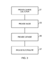
- Fig. 3 illustrates a method which may be used to form apparatus 1 such as the apparatus 1 of Fig. 1 .
- the example method comprises, at block 31, providing an electrode 3 comprising metal and at block 33, providing an anode 5 comprising a composite of halide salt and conductive carbon based material.
- the anode 5 may be deposited on the electrode 3.
- the method also comprises, at block 35, providing a cathode 9 comprising metal and, at block 37 providing a solid electrolyte 7 between the cathode 9 and the anode 5.
- the blocks of the method may be carried out in any suitable order. Two or more of the blocks may be performed simultaneously. For instance, in some examples the electrode 3 and the cathode 9 may be printed simultaneously. A gap may be provided between the electrode 3 and the cathode 9. The anode 5 may then be coated on the electrode 3 and the electrolyte 7 may be coated on the cathode 9. The two parts may then be combined to form the apparatus 1.
- any suitable techniques may be used to fabricate the respective parts of the apparatus 1.
- the techniques which are used may depend on the materials that are used for the respective parts.
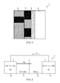
- Fig. 4 illustrates a battery 41 comprising an apparatus 1 as described above.
- the electrode 3 and the cathode 9 may be formed from the same material. This may enable the electrode 3 and the cathode 9 to be formed at the same time. This may reduce the number of different blocks of a method needed to fabricate the battery 41.
- the cathode 9 and the electrode 3 comprise silver.
- the cathode 9 and the electrode 3 were formed by screen printing onto a substrate 43. Other methods maybe used in other examples of the disclosure.
- the cathode 9 has the same size and shape as the electrode 3. It is to be appreciated that in other examples the cathode 9 could have a different size and/or shape to the electrode 3.
- a gap 45 is provided between the electrode 3 and the cathode 9.
- the gap 45 is 2mm. Other sized gaps may be used in other examples.
- the electrode 3 and a cathode 9 are printed on a substrate 43.
- the substrate 43 may be a flexible substrate which may enable the battery to be rolled up and/or bent.
- the substrate 43 may comprise any suitable material such as polyethylene naphthalate (PEN) or any other suitable material.
- the anode 5 comprises a composite of reduced graphene oxide and lithium chloride.
- the reduced graphene oxide may be synthesised using any suitable technique.
- the reduced graphene oxide was formed by adding 10ml of a graphene oxide suspension to a mixture of L-ascorbic acid and hydrochloric acid. The mixture was then stirred vigorously at a temperature of 60 degrees C for 5 hours until a black suspension is formed. The suspension mixture was vacuum filtered through a glass frit filter while the mixture was still hot. The black solid which is captured by the filter was washed with large amounts of deionised water until the pH of the filtrate was measured as 7. The black solid was then washed with isoproponal and acetone. The final reduced graphene oxide comprises a black powder and is collected by drying the solid on the filter in a vacuum.
- the reduced graphene oxide is dispersed in deionised water.
- 10mg of reduced graphene oxide was dispersed in 10ml of deionised water.
- the suspension is then sonicated.
- the suspension was sonicated for 5 minutes.
- Lithium chloride in aqueous solution is then added to the suspension to form a reduced graphene oxide-lithium chloride ink.
- the lithium chloride is added so that the final concentration of lithium chloride in the ink has a desired level.
- the concentration of lithium chloride was 0.1M. Other concentrations may be used in other examples of the disclosure.
- the anode 5 is deposited on the electrode 3.
- the reduced graphene oxide-lithium chloride ink is drop cast on the electrode 3.
- Other means of depositing the anode 5 on the electrode 3 may be used in other examples of the disclosure.
- the reduced graphene oxide-lithium chloride ink had concentrations of 1 mg/ml for reduced graphene oxide and 0.1 M for lithium chloride.
- the solid electrolyte 7 comprises a composite of Nafion and graphene oxide and is deposited on the cathode 9.
- the Nafion-graphene oxide mixture is drop cast on the cathode 9.
- Other means of depositing the electrolyte 7 on the cathode 9 may be used in other examples of the disclosure.
- Nafion-graphene oxide mixture had concentrations of 0.5mg/ml graphene oxide and ca 2.5%wt Nafion. Other concentrations may be used in other examples of the disclosure.
- the solid electrolyte 7 is deposited so that it overlaps a portion of the anode 5 so that a junction is formed between the anode 5 and the electrolyte 7.
- the example battery 41 of Fig. 4 provides a high specific capacity.
- a discharge test was carried out at 30 °C and 70% relative humidity and the battery 41 provided a capacity by area of 50 ⁇ Ah/cm 2 and a specific capacity of 4.75 Ah/g. Only active material was considered in the calculation of the specific capacity of the battery 41.
- Fig. 5 illustrates another battery 51 which may comprise a plurality of apparatus 1.
- the battery 51 is printed over a large surface area and may be used when flexed and/or bent.
- Each of the apparatus 1 within the battery 51 comprises an electrode 3, an anode 5, a solid electrolyte 7 and a cathode 9.
- the battery 51 may also be provided on a substrate 43 which may be as described above.
- a plurality of cathodes 9 and electrodes 3 are printed onto the substrate 43.
- the plurality of cathodes 9 and electrodes 3 may be printed in an interdigitated structure.
- the interdigitated structure may provide for a large active area for the battery 51.
- the anodes 5 may comprise any suitable composite of conductive carbon material and alkali metal salt.
- the anodes 5 could comprise a composite of reduced graphene oxide and lithium chloride as used in the example battery 41 of Fig. 4 .
- the anodes 5 are deposited on the electrodes 3.
- the solid electrolyte 7 comprises any suitable material such as a composite of Nafion and graphene oxide.
- the solid electrolyte 7 is deposited on the cathode 9.
- the solid electrolyte 7 overlaps portions of the anodes 5 so that junctions are formed between the anodes 5 and the solid electrolyte 7 which may be as described above.
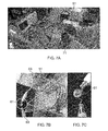
- Figs. 6A to 6D illustrate an example battery 51 in use.
- the battery 51 could be a battery 51 as illustrated in Fig. 5 and described above.
- a battery 51 of the required size is obtained.
- a large battery 51 is provided on a substrate 43.
- a battery 51 of a desired size is obtained by cutting the substrate 43 between adjacent cathodes 9 and electrodes 3.
- the battery 51 may be cut using any suitable technique. As the battery 51 is provided on a flexible substrate 43 formed from a material such as PEN the substrate 43 may be cut using scissors or any other readily available cutting implement. This may enable mass production of batteries 51 as a large number of batteries 51 can be printed on the same substrate 43 and then separated after fabrication.
- Fig. 6B illustrates the battery 51 which has been cut down to the required size.
- contacts 63 are connected to the cathode 9 and the electrode 3.
- the contacts 63 connect the battery to an LED (light emitting diode) 61.
- Fig. 6D shows a close up of the LED 61 of Fig. 6C.
- Fig 6D shows that the LED 61 is illuminated by the power provided from the battery 51.
- Figs. 7A to 7C illustrate another example battery 51 in use.
- the battery 51 could be a battery 51 as illustrated in Figs. 5 and 6A to 6B and described above.
- Fig. 7A the battery 51 is bent into a curved shape.
- the battery 51 is provided on a flexible substrate 43 so that a user may bend the battery 5 using their hands 71 and without and specialist tools.
- the battery 51 is bent into a curved shape. In other examples the battery 51 may be bent into other different shapes or configurations.
- contacts 63 are connected to the cathode 9 and the electrode 3 of the curved battery 51.
- the contacts 63 connected the battery to an LED 61.
- Fig. 7C shows a close up of the LED 65 from Fig. 7B.
- Fig 7B shows that the LED 61 is illuminated by the power provided from the battery 51 even when the battery 51 is bent.
- Fig. 8 illustrates another example battery 51.
- the battery 51 could be a battery 51 as illustrated in Figs. 5 and 6A to 7C and described above.
- Fig. 8 the battery 51 is rolled into a cylindrical shape.
- the cylindrical battery 51 may still be used to power electronic devices. It is to be appreciated that in other examples the battery 51 may be bent into other different shapes or configurations.
- Figs. 9A and 9B illustrated plots of data obtained using example apparatus 1.
- the data of Figs. 9A and 9B was obtained using a battery 41 such as the battery of Fig. 4 .
- the data was obtained from tests carried out in an environmental chamber and 30°C and at 70% humidity.
- Fig. 9A is a plot of open circuit voltage and current.
- the upper plot 91 shows data obtained with a proton battery comprising potassium hydroxide.
- the proton battery used a room temperature ionic liquid electrolyte to boost the current within the battery.
- triethylsulfonium bis(trifluoromethane)sulfonimide was used as the room temperature ionic liquid electrolyte.
- the lower plot 93 shows data obtained with the battery 41 of Fig. 4 .
- the concentration of the lithium chloride within the composite of the anode 5 was 0.1 M.
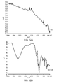
- Fig. 9B is a plot of voltage and time which shows the time taken for the respective batteries to discharge.
- the plot 95 shows data obtained with a proton battery and shows that the proton battery discharges very quickly.
- the plot 97 shows data obtained with the battery 41 of Fig. 4 and shows that the batteries made according to examples of the disclosure discharge much more slowly than the proton batteries.
- Fig. 10 shows plots of data obtained from batteries 41 having different concentrations of lithium chloride.
- Fig. 10 is a plot of voltage and time which shows the time taken for the respective batteries 41 to discharge.
- the data was obtained using batteries 41 formed as described in relation to Fig. 4 .
- the first plot 101 was obtained with a concentration of 1 M lithium chloride and the second plot 103 was obtained with a concentration of 0.1M lithium chloride.
- the data was obtained from tests carried out in an environmental chamber and 30°C and at 70% relative humidity.
- the plots of Fig. 10 show that the increase in concentration of the lithium chloride increases the initial open circuit voltage from 0.45V to 0.55V and increases the discharge plateau voltage from 0.2V to 0.4V. This indicates that the difference in work function between the anode 5 and the cathode 9 is not the main factor in determining the voltage of the battery 41.
- the plots show that improved performance is achieved by increasing the concentration of lithium chloride which indicates that a concentration cell effect exists. This may enable the voltage of the batteries 41, 51 to be tuned by controlling the concentration of the halide salts within the anode 5.
- Fig. 11 shows plots of data obtained from batteries 41 having different lithium halides within the anodes 5.
- Fig. 11 is a plot of voltage and time which shows the time taken for the respective batteries 41 to discharge. The data was obtained from tests carried out in an environmental chamber and 30°C and at 70% relative humidity.
- the data was obtained using batteries 41 formed as described in relation to Fig. 4 .
- the first plot 111 was obtained using lithium chloride
- the second plot 113 was obtained using lithium bromide
- the third plot 115 was obtained using lithium iodide.
- the fourth plot 117 was also obtained using lithium iodide however to obtain the data for the fourth plot 117 the cathode 9 used comprised silver with a layer of silver nitrate.
- the difference in performance which is achieved with the different halides indicates that the lithium ion plays a limited role in the mechanisms for providing power in apparatus 1 according to examples of the disclosure. This is different to lithium ion based batteries in which the lithium ion is key to charge transfer.
- Fig. 12A illustrates a Fourier transform infrared (FTIR) spectrum of fully reduced graphene oxide which may be used in example apparatus 1.
- Fig. 12B illustrates a Fourier transform infrared (FTIR) spectrum of graphene oxide-potassium hydroxide.
- the reduced graphene oxide may be prepared by reducing graphene oxide with any suitable reducing agent such as ascorbic acid. This may enable fully and/or highly reduced graphene oxide to be obtained.
- the spectrum for the fully reduced graphene oxide shows that there are no band gaps within the structure. This indicates that the oxygen and/or other functional groups have been removed from the graphene structure. Any remaining oxygen and/or functional groups are minimal and do not affect the overall structure and electrical conductivity of the reduced graphene oxide.
- the fully reduced graphene oxide may have a high conductivity.
- the spectrum for the graphene oxide-potassium hydroxide shows that the band features typical of graphene oxide are still present. This indicates that the graphene oxide has only been partially reduced.
- the graphene oxide-potassium hydroxide has a much lower electrical conductivity than the fully reduced graphene oxide.
- Reduced graphene oxide which was used in some of the above described examples was characterised by X-ray photoelectron spectroscopy and found to have a composition of 84% carbon, 15% oxygen and 1% other elements. After the lithium chloride was added to form a composite the composition was found to be 39% carbon, 6% oxygen, 26% lithium, 26% chlorine and 3% other elements.
- Examples of the disclosure provide apparatus 1 which may be used to provide power sources.
- the apparatus 1 comprises a plurality of solid layers and does not require any liquid or gels. In particular there are no liquid or gel electrolytes needed to facilitate the charge transfer. This may provide a simpler apparatus 1 which may be simpler to fabricate.
- the methods which are use to fabricate the apparatus 1 may be easily scaled up as only a small number of blocks of the process are needed. Furthermore, as water based processing is required there is no need for the apparatus 1 to be fabricated in an inert or water-free environment.
- a required level of humidity may be required to use the apparatus 1. This may enable the apparatus 1 to be used in environmental conditions without additional packaging.
- fully reduced graphene oxide is used as the conductive carbon material within the anode 5.
- the reduce graphene oxide has more defects than graphene and may have a lower conductivity it may be cheaper to fabricate and may enable simpler fabrication techniques to be used.
- reduced graphene oxide is dispersible in water it may be used to form an ink and printed on to the electrode 3 or other components of the apparatus 1. This may facilitate mass production of the apparatus 1.
- Coupled means operationally coupled. Any number of intervening components may be provided including no intervening components.
- example or “for example” or “may” in the text denotes, whether explicitly stated or not, that such features or functions are present in at least the described example, whether described as an example or not, and that they can be, but are not necessarily, present in some of or all other examples.
- example “for example” or “may” refers to a particular instance in a class of examples.
- a property of the instance can be a property of only that instance or a property of the class or a property of a subclass of the class that includes some but not all of the instances in the class. It is therefore implicitly disclosed that a features described with reference to one example but not with reference to another example, can where possible be used in that other example but does not necessarily have to be used in that other example.
Abstract
Description
- Examples of the disclosure relate to an apparatus and method of providing an apparatus for use as a power source. In particular, they relate to an apparatus and method of providing an apparatus for use as a power source where the apparatus comprises conductive carbon based materials.
- Apparatus, such as batteries, for providing a power source are known. Some batteries, such as proton batteries rely on the transport of protons between an anode and cathode to provide a power source. Such apparatus typically require the use of an electrolyte such as a room temperature ionic liquid electrolyte to facilitate the transfer of protons across the junction of the apparatus.
- Such apparatus may be difficult to fabricate and store as they may require liquids to be positioned within the apparatus.
- It is useful to provide improved apparatus for use as a power source and methods of providing such apparatus.
- According to various, but not necessarily all, examples of the disclosure there may be provided an apparatus comprising: an electrode comprising metal; an anode comprising a composite of halide salt and conductive carbon based material wherein the anode is deposited on the electrode; a cathode comprising metal; and a solid electrolyte provided between the cathode and the anode.
- In some examples the conductive carbon based material may comprise graphene.
- In some examples the conductive carbon based material may comprise reduced graphene oxide.
- In some examples the conductive carbon based material may be formed from an ink comprising reduced graphene oxide in solution.
- In some examples the anode may be arranged to react with the metal from the electrode to form metal halide and release metal cations. Transport of the released metal cations from the electrode to the cathode provides a power source.
- In some examples the metal may comprise a thin metal foil layer.
- In some examples the cathode may comprise the same metal as the electrode.
- In some examples the metal may comprise silver.
- In some examples the solid electrolyte may be arranged to absorb ambient water to enable transport of cations across the solid electrolyte
- In some examples the solid electrolyte may comprise graphene oxide.
- In some examples the solid electrolyte may comprise Nafion.
- According to various, but not necessarily all, examples of the disclosure there may be provided a battery comprising an apparatus as described above.
- According to various, but not necessarily all, examples of the disclosure there may be provided a method comprising: providing an electrode comprising metal; providing an anode comprising a composite of halide salt and conductive carbon based material wherein the anode is deposited on the electrode; providing a cathode comprising metal; and providing a solid electrolyte between the cathode and the anode.
- In some examples the conductive carbon based material may comprise graphene.
- In some examples the conductive carbon based material may comprise reduced graphene oxide.
- In some examples the method may comprise forming the conductive carbon based material from an ink comprising reduced graphene oxide in solution.
- In some examples the anode may be arranged to react with the metal from the electrode to form metal halide and release metal cations. Transport of the released metal cations from the electrode to the cathode may provide a power source.
- In some examples the metal may comprise a thin metal foil layer.
- In some examples the cathode may comprise the same metal as the electrode.
- In some examples the metal may comprise silver.
- In some examples the solid electrolyte may be arranged to absorb ambient water to enable transport of cations across the solid electrolyte
- In some examples the solid electrolyte may comprise graphene oxide.
- In some examples the solid electrolyte may comprise Nafion.
- According to various, but not necessarily all, examples of the disclosure there is provided examples as claimed in the appended claims.
- For a better understanding of various examples that are useful for understanding the detailed description, reference will now be made by way of example only to the accompanying drawings in which:
-
Fig.1 illustrates an apparatus; -
Fig. 2 illustrates a mechanism for charge transport in an example apparatus; -
Fig. 3 illustrates a method; -
Fig. 4 illustrates a battery comprising an apparatus; -
Fig. 5 illustrates a battery comprising a plurality of apparatus; -
Figs. 6A to 6D illustrate an example battery in use; -
Figs. 7A to 7C illustrate another example battery in use; -
Fig. 8 illustrates an example battery; -
Figs. 9A and 9D illustrate plots of data obtained using example apparatus; -
Fig. 10 illustrates a plot of data obtained using example apparatus; -
Fig. 11 illustrates a plot of data obtained using example apparatus; and -
Figs. 12A and 12B illustrate spectra of reduced graphene oxide and graphene oxide-potassium hydroxide. - The figures illustrate an
apparatus 1 and method of providing anapparatus 1. Theapparatus 1 comprises: anelectrode 3 comprising metal; ananode 5 comprising a composite of halide salt and conductive carbon based material wherein the anode is deposited on theelectrode 3; acathode 9 comprising metal; and asolid electrolyte 7 provided between thecathode 9 and theanode 5. - The
apparatus 1 may be for use as a power source. For instance, the power source may be used to provide power to components of an electronic device. The electronic device could be a communication device or any other suitable device. Theapparatus 1 may be provided within abattery -
Fig. 1 schematically illustrates anexample apparatus 1 which may be provided in examples of the disclosure. Theapparatus 1 comprises anelectrode 3, an anode 5 asolid electrolyte 7 and acathode 9. Theelectrode 3,anode 5,solid electrolyte 7 andcathode 9 may be arranged in a planar structure. Other arrangements of respective components may be used in other examples of the disclosure. - The
electrode 3 may comprise any means which provides a path for charges to theanode 5. In some examples theelectrode 3 may comprise a metal. In some examples theelectrode 3 may comprise a thin layer of metal. In some examples theelectrode 3 may comprise a thin metal foil. The metal foil may be thin so that theapparatus 1 forms aflexible apparatus 1 which may be easily deformed and/or rolled up. Theelectrode 3 may combine with theanode 5 to enable chemical reactions which allow theapparatus 1 to be used as a power source. - Any suitable metal may be used for the
electrode 3. The metal which is used for theelectrode 3 may depend on the materials that are used within theanode 5. In some examples theelectrode 3 may comprise silver, aluminium, copper, zinc or any other suitable metal. - The
anode 5 may comprise any means which may be arranged as a source of positive charges for theapparatus 1. In examples of the disclosure theanode 5 comprises a composite of a halide salt and conductive carbon based material. - The conductive carbon based material may comprise any conductive material comprising carbon which enables halide salts such as alkali metal halides to be mixed within it. The conductive carbon material may provide a support structure through which the halide salt may be distributed. The use of a conductive material may facilitate the transfer of cations from the
electrode 3 and through theapparatus 1. - In some examples the conductive carbon based material comprises graphene. In some examples the conductive carbon based material may comprise reduced graphene oxide. In such examples the conductive carbon based material of the
anode 5 may be formed from an ink comprising reduced graphene oxide in solution. - The reduced graphene oxide may be fully reduced graphene oxide or highly reduced graphene oxide. The fully reduced graphene oxide may have all or almost all of the oxygen and/or any other functional groups removed from the graphene structure. This may ensure a high level of electrical conductivity for the reduced graphene oxide.
- The halide salt may comprise any salt comprising a halogen. The halogen could comprise chlorine, bromine, iodine or any other suitable halogen. In some examples the halide salt could comprise alkali metal. In such examples the alkali metal could comprise lithium, sodium, potassium or any other suitable alkali metal.
- In examples of the disclosure the
anode 5 is deposited on theelectrode 3. Theanode 5 may be deposited on theelectrode 3 so that charges from theelectrode 3 may be transferred to theanode 5. In some examples the anode may be arranged so that the metal from theelectrode 3 reacts with theanode 5 to form metal halide and release metal cations. In some examples of the disclosure theanode 5 may be printed on theelectrode 3. - The
electrolyte 7 may comprise any means which may provide for the conduction of free ions between theanode 5 andcathode 9. In some examples theelectrolyte 7 may provide for the conduction of cations. Theelectrolyte 7 may provide for the conduction of metal cations from theelectrode 3. Theelectrolyte 7 may enable the transfer of cations form theanode 5 to thecathode 9. In examples of the disclosure theelectrolyte 7 may be asolid electrolyte 7. - In some examples the
solid electrolyte 7 may comprise an insulating material. The insulating material may comprise a material which enables transfer of cations but does not conduct anions or electrons. In some examples the insulating material may comprise graphene oxide. - The graphene oxide may be provided within a composite comprising a polymeric material. In some examples the graphene oxide may be present in a higher quantity than the polymeric material. For instance in some examples the graphene oxide may comprise 25 times the weight of the polymeric material. It is to be appreciated that other proportions of graphene oxide and polymeric material may be used in other examples of the disclosure.
- The polymeric material may comprise a material which enables transfer of cations but does not conduct anions or electrons. In some examples the polymeric material may comprise a tetrafluorethylene based polymer such as Nafion. Nafion may have a high conductivity for protons and cations.
- The ionic conductivity of the
solid electrolyte 7 may be dependent upon the relative humidity of the environment around theapparatus 1. This may require theapparatus 1 to be used in a humid environment. For example it may require humidity levels between 30% and 70%. - The
solid electrolyte 7 is provided between theanode 5 and thecathode 9. Thesolid electrolyte 7 may be positioned so that a junction is formed between thesolid electrolyte 7 and theanode 5. The junction may enable cations to be transferred from theanode 5 to thesolid electrolyte 7. Thesolid electrolyte 7 may also be positioned to form a junction with thecathode 9. The junction with thecathode 9 may enable cations to be transferred from thesolid electrolyte 7 to thecathode 9. - The
cathode 9 may comprise any means which may be arranged to attract positive charges from theanode 5. In some examples thecathode 9 may comprise a metal. In some examples the metal used for thecathode 9 may be the same as the metal used for theelectrode 3. In some examples the metal used for thecathode 9 may be different to the metal used for theelectrode 3. In some examples thecathode 9 may comprise a thin metal foil. The metal foil may be thin so that theapparatus 1 forms aflexible apparatus 1 which may be easily deformed and/or rolled up. - Any suitable metal may be used for the
cathode 9. In some examples thecathode 9 may comprise silver, aluminium, copper, zinc or any other suitable metal. - In some examples the
cathode 9 may comprise a plurality of layers of different materials. For instance in some examples thecathode 9 could comprise a layer of silver coated with a layer of silver nitrate. This layer of silver nitrate may provide silver cations for the cathode reduction reaction which comprises the combination of the silver cations with free electrons to form silver. - It is to be appreciated that only features necessary for the description are illustrated in
Fig. 1 . It is to be appreciated that theapparatus 1 may comprise other components which are not illustrated inFig. 1 . For instance, theapparatus 1 may be provided on a flexible substrate and/or may comprises encapsulating or packaging layers. - The
apparatus 1 may be provided on a substrate to form abattery Figs. 4 to 8 . -
Fig. 2 illustrates an example mechanism for charge transport in anexample apparatus 1. The example apparatus ofFig. 2 comprises anelectrode 3, an anode 5 asolid electrolyte 7 and acathode 9 which may be as described above. Corresponding reference numerals are used for corresponding features. - In the example of
Fig. 2 theelectrode 3 and thecathode 9 comprise silver Ag. Theanode 5 comprises a composite of lithium halide LiX within a reduced graphene oxide structure. InFig. 2 X represents any halide. It is to be appreciated that other metals could be used in place of lithium and/or silver in other examples of the disclosure. Thesolid electrolyte 7 comprises a mixture of graphene oxide and Nafion. - The
apparatus 1 may be arranged to provide a source of power. In use the lithium halide LiX may react with the metal of theelectrode 3 to form silver halide AgX and a free electron e-. This reaction may also produce silver cations Ag+. - The silver cations Ag+ are conducted through conductive carbon material of the
cathode 5 and through theelectrolyte 7 to thecathode 9. At thecathode 9 the silver cations Ag+ recombine with free electrons e- to form silver Ag. - Therefore the
apparatus 1 provides a mechanism for charge transport between theanode 5 andcathodes 9 which may be used to provide power to devices such as electronic devices. - In the example of
Fig. 2 thesolid electrolyte 7 requires ambient water in order to enable the transport of the cations. This may require theapparatus 1 to be used within a humid environment. In some examples thesolid electrolyte 7 may be arranged to transport cations if the relative humidity of the environment is between 30% to 70%. As normal ambient conditions are usually between 50% and 70% relative humidity this may enable theapparatus 1 to be used in normal ambient conditions. This may enable theapparatus 1 to be fabricated without packaging, such as hermetic sealing, which may be arranged to keep water out of theapparatus 1. This may make theapparatus 1 simpler to fabricate. In other examples hermetic sealing may be provided around theapparatus 1 to keep water out of theapparatus 1 until theapparatus 1 needs to be used. - Also, as the environmental humidity is needed to enable the Nafion to transport the cations the circuit path between the
anode 5 and thecathode 9 can be broken by placing theapparatus 1 in an environment which does not have the required humidity levels. For instance, if theapparatus 1 is stored in a vacuum packaging there is no ambient water to enable the charge transfer through thesolid electrolyte 7. This may prevent any reactions from occurring within theapparatus 1. As the lack of humidity prevents the reactions within theapparatus 1 theapparatus 1 may be stored for a long time without any degradation of theapparatus 1. This may provide a simple and effective method for storing theapparatus 1 which may increase the shelf life of theapparatus 1 and any devices which theapparatus 1 may be comprised within. -
Fig. 3 illustrates a method which may be used to formapparatus 1 such as theapparatus 1 ofFig. 1 . The example method comprises, atblock 31, providing anelectrode 3 comprising metal and atblock 33, providing ananode 5 comprising a composite of halide salt and conductive carbon based material. Theanode 5 may be deposited on theelectrode 3. The method also comprises, at block 35, providing acathode 9 comprising metal and, atblock 37 providing asolid electrolyte 7 between thecathode 9 and theanode 5. - It is to be appreciated that the blocks of the method may be carried out in any suitable order. Two or more of the blocks may be performed simultaneously. For instance, in some examples the
electrode 3 and thecathode 9 may be printed simultaneously. A gap may be provided between theelectrode 3 and thecathode 9. Theanode 5 may then be coated on theelectrode 3 and theelectrolyte 7 may be coated on thecathode 9. The two parts may then be combined to form theapparatus 1. - It is to be appreciated that any suitable techniques may be used to fabricate the respective parts of the
apparatus 1. The techniques which are used may depend on the materials that are used for the respective parts. -
Fig. 4 illustrates abattery 41 comprising anapparatus 1 as described above. - The
electrode 3 and thecathode 9 may be formed from the same material. This may enable theelectrode 3 and thecathode 9 to be formed at the same time. This may reduce the number of different blocks of a method needed to fabricate thebattery 41. - In the example of
Fig. 4 thecathode 9 and theelectrode 3 comprise silver. Thecathode 9 and theelectrode 3 were formed by screen printing onto asubstrate 43. Other methods maybe used in other examples of the disclosure. - In the example of
Fig. 4 thecathode 9 has the same size and shape as theelectrode 3. It is to be appreciated that in other examples thecathode 9 could have a different size and/or shape to theelectrode 3. - A
gap 45 is provided between theelectrode 3 and thecathode 9. In the example ofFig. 4 thegap 45 is 2mm. Other sized gaps may be used in other examples. - In the
example battery 41 ofFig. 4 theelectrode 3 and acathode 9 are printed on asubstrate 43. Thesubstrate 43 may be a flexible substrate which may enable the battery to be rolled up and/or bent. Thesubstrate 43 may comprise any suitable material such as polyethylene naphthalate (PEN) or any other suitable material. - In the example of
Fig. 4 theanode 5 comprises a composite of reduced graphene oxide and lithium chloride. - The reduced graphene oxide may be synthesised using any suitable technique. In the example of
Fig. 4 the reduced graphene oxide was formed by adding 10ml of a graphene oxide suspension to a mixture of L-ascorbic acid and hydrochloric acid. The mixture was then stirred vigorously at a temperature of 60 degrees C for 5 hours until a black suspension is formed. The suspension mixture was vacuum filtered through a glass frit filter while the mixture was still hot. The black solid which is captured by the filter was washed with large amounts of deionised water until the pH of the filtrate was measured as 7. The black solid was then washed with isoproponal and acetone. The final reduced graphene oxide comprises a black powder and is collected by drying the solid on the filter in a vacuum. - To form the composite with lithium chloride the reduced graphene oxide is dispersed in deionised water. In the example of
Fig. 4 10mg of reduced graphene oxide was dispersed in 10ml of deionised water. The suspension is then sonicated. In the example ofFig. 4 the suspension was sonicated for 5 minutes. Lithium chloride in aqueous solution is then added to the suspension to form a reduced graphene oxide-lithium chloride ink. The lithium chloride is added so that the final concentration of lithium chloride in the ink has a desired level. In the example ofFig. 4 the concentration of lithium chloride was 0.1M. Other concentrations may be used in other examples of the disclosure. - The
anode 5 is deposited on theelectrode 3. In the example ofFig. 4 the reduced graphene oxide-lithium chloride ink is drop cast on theelectrode 3. Other means of depositing theanode 5 on theelectrode 3 may be used in other examples of the disclosure. - In the
battery 41 ofFig. 4 5µl of reduced graphene oxide-lithium chloride ink were deposited. The reduced graphene oxide-lithium chloride ink had concentrations of 1 mg/ml for reduced graphene oxide and 0.1 M for lithium chloride. - The
solid electrolyte 7 comprises a composite of Nafion and graphene oxide and is deposited on thecathode 9. In the example ofFig. 4 the Nafion-graphene oxide mixture is drop cast on thecathode 9. Other means of depositing theelectrolyte 7 on thecathode 9 may be used in other examples of the disclosure. - In the
battery 41 ofFig. 4 10µl of Nafion-graphene oxide mixture was deposited. The Nafion-graphene oxide mixture had concentrations of 0.5mg/ml graphene oxide and ca 2.5%wt Nafion. Other concentrations may be used in other examples of the disclosure. - The
solid electrolyte 7 is deposited so that it overlaps a portion of theanode 5 so that a junction is formed between theanode 5 and theelectrolyte 7. - The
example battery 41 ofFig. 4 provides a high specific capacity. A discharge test was carried out at 30 °C and 70% relative humidity and thebattery 41 provided a capacity by area of 50 µAh/cm2 and a specific capacity of 4.75 Ah/g. Only active material was considered in the calculation of the specific capacity of thebattery 41. -
Fig. 5 illustrates anotherbattery 51 which may comprise a plurality ofapparatus 1. Thebattery 51 is printed over a large surface area and may be used when flexed and/or bent. Each of theapparatus 1 within thebattery 51 comprises anelectrode 3, ananode 5, asolid electrolyte 7 and acathode 9. Thebattery 51 may also be provided on asubstrate 43 which may be as described above. - In the
example battery 51 ofFig. 5 a plurality ofcathodes 9 andelectrodes 3 are printed onto thesubstrate 43. The plurality ofcathodes 9 andelectrodes 3 may be printed in an interdigitated structure. The interdigitated structure may provide for a large active area for thebattery 51. - The
anodes 5 may comprise any suitable composite of conductive carbon material and alkali metal salt. Theanodes 5 could comprise a composite of reduced graphene oxide and lithium chloride as used in theexample battery 41 ofFig. 4 . Theanodes 5 are deposited on theelectrodes 3. - The
solid electrolyte 7 comprises any suitable material such as a composite of Nafion and graphene oxide. Thesolid electrolyte 7 is deposited on thecathode 9. Thesolid electrolyte 7 overlaps portions of theanodes 5 so that junctions are formed between theanodes 5 and thesolid electrolyte 7 which may be as described above. -
Figs. 6A to 6D illustrate anexample battery 51 in use. Thebattery 51 could be abattery 51 as illustrated inFig. 5 and described above. - In
Fig. 6A abattery 51 of the required size is obtained. InFig. 6A alarge battery 51 is provided on asubstrate 43. Abattery 51 of a desired size is obtained by cutting thesubstrate 43 betweenadjacent cathodes 9 andelectrodes 3. - The
battery 51 may be cut using any suitable technique. As thebattery 51 is provided on aflexible substrate 43 formed from a material such as PEN thesubstrate 43 may be cut using scissors or any other readily available cutting implement. This may enable mass production ofbatteries 51 as a large number ofbatteries 51 can be printed on thesame substrate 43 and then separated after fabrication. -
Fig. 6B illustrates thebattery 51 which has been cut down to the required size. - In
Fig. 6C contacts 63 are connected to thecathode 9 and theelectrode 3. Thecontacts 63 connect the battery to an LED (light emitting diode) 61. -
Fig. 6D shows a close up of theLED 61 ofFig. 6C. Fig 6D shows that theLED 61 is illuminated by the power provided from thebattery 51. -
Figs. 7A to 7C illustrate anotherexample battery 51 in use. Thebattery 51 could be abattery 51 as illustrated inFigs. 5 and6A to 6B and described above. - In
Fig. 7A thebattery 51 is bent into a curved shape. In the example ofFig. 7A thebattery 51 is provided on aflexible substrate 43 so that a user may bend thebattery 5 using theirhands 71 and without and specialist tools. - In the example of
Fig. 7A thebattery 51 is bent into a curved shape. In other examples thebattery 51 may be bent into other different shapes or configurations. - In
Fig. 7B contacts 63 are connected to thecathode 9 and theelectrode 3 of thecurved battery 51. Thecontacts 63 connected the battery to anLED 61. -
Fig. 7C shows a close up of theLED 65 fromFig. 7B. Fig 7B shows that theLED 61 is illuminated by the power provided from thebattery 51 even when thebattery 51 is bent. -
Fig. 8 illustrates anotherexample battery 51. Thebattery 51 could be abattery 51 as illustrated inFigs. 5 and6A to 7C and described above. - In
Fig. 8 thebattery 51 is rolled into a cylindrical shape. Thecylindrical battery 51 may still be used to power electronic devices. It is to be appreciated that in other examples thebattery 51 may be bent into other different shapes or configurations. -
Figs. 9A and 9B illustrated plots of data obtained usingexample apparatus 1. The data ofFigs. 9A and 9B was obtained using abattery 41 such as the battery ofFig. 4 . In bothFig. 9A and 9B the data was obtained from tests carried out in an environmental chamber and 30°C and at 70% humidity. -
Fig. 9A is a plot of open circuit voltage and current. Theupper plot 91 shows data obtained with a proton battery comprising potassium hydroxide. The proton battery used a room temperature ionic liquid electrolyte to boost the current within the battery. To obtain the data inFig. 9A triethylsulfonium bis(trifluoromethane)sulfonimide was used as the room temperature ionic liquid electrolyte. - The
lower plot 93 shows data obtained with thebattery 41 ofFig. 4 . The concentration of the lithium chloride within the composite of theanode 5 was 0.1 M. -
Fig. 9B is a plot of voltage and time which shows the time taken for the respective batteries to discharge. Theplot 95 shows data obtained with a proton battery and shows that the proton battery discharges very quickly. - The
plot 97 shows data obtained with thebattery 41 ofFig. 4 and shows that the batteries made according to examples of the disclosure discharge much more slowly than the proton batteries. -
Fig. 10 shows plots of data obtained frombatteries 41 having different concentrations of lithium chloride.Fig. 10 is a plot of voltage and time which shows the time taken for therespective batteries 41 to discharge. - The data was obtained using
batteries 41 formed as described in relation toFig. 4 . Thefirst plot 101 was obtained with a concentration of 1 M lithium chloride and thesecond plot 103 was obtained with a concentration of 0.1M lithium chloride. The data was obtained from tests carried out in an environmental chamber and 30°C and at 70% relative humidity. - The plots of
Fig. 10 show that the increase in concentration of the lithium chloride increases the initial open circuit voltage from 0.45V to 0.55V and increases the discharge plateau voltage from 0.2V to 0.4V. This indicates that the difference in work function between theanode 5 and thecathode 9 is not the main factor in determining the voltage of thebattery 41. The plots show that improved performance is achieved by increasing the concentration of lithium chloride which indicates that a concentration cell effect exists. This may enable the voltage of thebatteries anode 5. -
Fig. 11 shows plots of data obtained frombatteries 41 having different lithium halides within theanodes 5.Fig. 11 is a plot of voltage and time which shows the time taken for therespective batteries 41 to discharge. The data was obtained from tests carried out in an environmental chamber and 30°C and at 70% relative humidity. - The data was obtained using
batteries 41 formed as described in relation toFig. 4 . Thefirst plot 111 was obtained using lithium chloride, thesecond plot 113 was obtained using lithium bromide and thethird plot 115 was obtained using lithium iodide. Thefourth plot 117 was also obtained using lithium iodide however to obtain the data for thefourth plot 117 thecathode 9 used comprised silver with a layer of silver nitrate. - The difference in performance which is achieved with the different halides indicates that the lithium ion plays a limited role in the mechanisms for providing power in
apparatus 1 according to examples of the disclosure. This is different to lithium ion based batteries in which the lithium ion is key to charge transfer. -
Fig. 12A illustrates a Fourier transform infrared (FTIR) spectrum of fully reduced graphene oxide which may be used inexample apparatus 1.Fig. 12B illustrates a Fourier transform infrared (FTIR) spectrum of graphene oxide-potassium hydroxide. - The reduced graphene oxide may be prepared by reducing graphene oxide with any suitable reducing agent such as ascorbic acid. This may enable fully and/or highly reduced graphene oxide to be obtained. The spectrum for the fully reduced graphene oxide shows that there are no band gaps within the structure. This indicates that the oxygen and/or other functional groups have been removed from the graphene structure. Any remaining oxygen and/or functional groups are minimal and do not affect the overall structure and electrical conductivity of the reduced graphene oxide. The fully reduced graphene oxide may have a high conductivity.
- The spectrum for the graphene oxide-potassium hydroxide shows that the band features typical of graphene oxide are still present. This indicates that the graphene oxide has only been partially reduced. The graphene oxide-potassium hydroxide has a much lower electrical conductivity than the fully reduced graphene oxide.
- Reduced graphene oxide which was used in some of the above described examples was characterised by X-ray photoelectron spectroscopy and found to have a composition of 84% carbon, 15% oxygen and 1% other elements. After the lithium chloride was added to form a composite the composition was found to be 39% carbon, 6% oxygen, 26% lithium, 26% chlorine and 3% other elements.
- Examples of the disclosure provide
apparatus 1 which may be used to provide power sources. - The
apparatus 1 comprises a plurality of solid layers and does not require any liquid or gels. In particular there are no liquid or gel electrolytes needed to facilitate the charge transfer. This may provide asimpler apparatus 1 which may be simpler to fabricate. - The methods which are use to fabricate the
apparatus 1 may be easily scaled up as only a small number of blocks of the process are needed. Furthermore, as water based processing is required there is no need for theapparatus 1 to be fabricated in an inert or water-free environment. - In examples of the disclosure which use polymer such as Nafion for the solid electrolyte a required level of humidity may be required to use the
apparatus 1. This may enable theapparatus 1 to be used in environmental conditions without additional packaging. - In examples of the disclosure fully reduced graphene oxide is used as the conductive carbon material within the
anode 5. Although the reduce graphene oxide has more defects than graphene and may have a lower conductivity it may be cheaper to fabricate and may enable simpler fabrication techniques to be used. As reduced graphene oxide is dispersible in water it may be used to form an ink and printed on to theelectrode 3 or other components of theapparatus 1. This may facilitate mass production of theapparatus 1. - In the above description the term "coupled" means operationally coupled. Any number of intervening components may be provided including no intervening components.
- The term "comprise" is used in this document with an inclusive not an exclusive meaning. That is any reference to X comprising Y indicates that X may comprise only one Y or may comprise more than one Y. If it is intended to use "comprise" with an exclusive meaning then it will be made clear in the context by referring to "comprising only one..." or by using "consisting".
- In this brief description, reference has been made to various examples. The description of features or functions in relation to an example indicates that those features or functions are present in that example. The use of the term "example" or "for example" or "may" in the text denotes, whether explicitly stated or not, that such features or functions are present in at least the described example, whether described as an example or not, and that they can be, but are not necessarily, present in some of or all other examples. Thus "example", "for example" or "may" refers to a particular instance in a class of examples. A property of the instance can be a property of only that instance or a property of the class or a property of a subclass of the class that includes some but not all of the instances in the class. It is therefore implicitly disclosed that a features described with reference to one example but not with reference to another example, can where possible be used in that other example but does not necessarily have to be used in that other example.
- Although embodiments of the present invention have been described in the preceding paragraphs with reference to various examples, it should be appreciated that modifications to the examples given can be made without departing from the scope of the invention as claimed.
- Features described in the preceding description may be used in combinations other than the combinations explicitly described.
- Although functions have been described with reference to certain features, those functions may be performable by other features whether described or not.
- Although features have been described with reference to certain embodiments, those features may also be present in other embodiments whether described or not.
- Whilst endeavoring in the foregoing specification to draw attention to those features of the invention believed to be of particular importance it should be understood that the Applicant claims protection in respect of any patentable feature or combination of features hereinbefore referred to and/or shown in the drawings whether or not particular emphasis has been placed thereon.
- Whilst endeavoring in the foregoing specification to draw attention to those features of the invention believed to be of particular importance it should be understood that the Applicant claims protection in respect of any patentable feature or combination of features hereinbefore referred to and/or shown in the drawings whether or not particular emphasis has been placed thereon.
Claims (15)
- An apparatus comprising:an electrode comprising metal;an anode comprising a composite of halide salt and conductive carbon based material wherein the anode is deposited on the electrode;a cathode comprising metal; anda solid electrolyte provided between the cathode and the anode.
- An apparatus as claimed in any preceding claim wherein the conductive carbon based material comprises graphene.
- An apparatus as claimed in any preceding claim wherein the conductive carbon based material comprises reduced graphene oxide.
- An apparatus as claimed in any preceding claim wherein the conductive carbon based material is formed from an ink comprising reduced graphene oxide in solution.
- An apparatus as claimed in any preceding claim wherein the anode is arranged to react with the metal from the electrode to form metal halide and release metal cations.
- An apparatus as claimed in claim 5 wherein transport of the released metal cations from the electrode to the cathode provides a power source.
- An apparatus as claimed in any preceding claim wherein the metal comprises a thin metal foil layer.
- An apparatus as claimed in any preceding claim wherein the cathode comprises the same metal as the electrode.
- An apparatus as claimed in any preceding claim wherein the metal comprises silver.
- An apparatus as claimed in any preceding claim wherein the solid electrolyte is arranged to absorb ambient water to enable transport of cations across the solid electrolyte
- An apparatus as claimed in any preceding claim wherein the solid electrolyte comprises graphene oxide.
- An apparatus as claimed in any preceding claim wherein the solid electrolyte comprises Nafion.
- A battery comprising an apparatus as claimed in any of claims 1 to 12.
- A method comprising:providing an electrode comprising metal;providing an anode comprising a composite of halide salt and conductive carbon based material wherein the anode is deposited on the electrode;providing a cathode comprising metal; andproviding a solid electrolyte between the cathode and the anode.
- A method as claimed in claim 14 wherein the conductive carbon based material comprises reduced graphene oxide.
Priority Applications (3)
| Application Number | Priority Date | Filing Date | Title |
|---|---|---|---|
| EP15185847.9A EP3145003B1 (en) | 2015-09-18 | 2015-09-18 | An apparatus and method of providing an apparatus for use as a power source |
| PCT/FI2016/050629 WO2017046448A1 (en) | 2015-09-18 | 2016-09-12 | An apparatus and method of providing an apparatus for use as a power source |
| US15/759,462 US10840505B2 (en) | 2015-09-18 | 2016-09-12 | Apparatus and method of providing an apparatus for use as a power source |
Applications Claiming Priority (1)
| Application Number | Priority Date | Filing Date | Title |
|---|---|---|---|
| EP15185847.9A EP3145003B1 (en) | 2015-09-18 | 2015-09-18 | An apparatus and method of providing an apparatus for use as a power source |
Publications (2)
| Publication Number | Publication Date |
|---|---|
| EP3145003A1 true EP3145003A1 (en) | 2017-03-22 |
| EP3145003B1 EP3145003B1 (en) | 2019-09-04 |
Family
ID=54150322
Family Applications (1)
| Application Number | Title | Priority Date | Filing Date |
|---|---|---|---|
| EP15185847.9A Not-in-force EP3145003B1 (en) | 2015-09-18 | 2015-09-18 | An apparatus and method of providing an apparatus for use as a power source |
Country Status (3)
| Country | Link |
|---|---|
| US (1) | US10840505B2 (en) |
| EP (1) | EP3145003B1 (en) |
| WO (1) | WO2017046448A1 (en) |
Families Citing this family (2)
| Publication number | Priority date | Publication date | Assignee | Title |
|---|---|---|---|---|
| US11251430B2 (en) | 2018-03-05 | 2022-02-15 | The Research Foundation For The State University Of New York | ϵ-VOPO4 cathode for lithium ion batteries |
| CN108417888A (en) * | 2018-03-22 | 2018-08-17 | 上海力信能源科技有限责任公司 | A kind of no lithium salts modified graphene composite solid electrolyte material, dielectric film and preparation method thereof |
Citations (3)
| Publication number | Priority date | Publication date | Assignee | Title |
|---|---|---|---|---|
| US2428850A (en) * | 1941-12-26 | 1947-10-14 | Burgess Battery Co | Deferred action dry cell with magnesium electrode |
| US2930830A (en) * | 1955-08-02 | 1960-03-29 | Leesona Corp | Solid-state cell and battery |
| WO2014188059A1 (en) * | 2013-05-23 | 2014-11-27 | Nokia Corporation | Proton-battery based on graphene derivatives |
Family Cites Families (14)
| Publication number | Priority date | Publication date | Assignee | Title |
|---|---|---|---|---|
| DE102009054939A1 (en) | 2009-12-18 | 2011-06-22 | SB LiMotive Company Ltd., Kyonggi | Galvanic element |
| US9558860B2 (en) | 2010-09-10 | 2017-01-31 | Samsung Electronics Co., Ltd. | Graphene-enhanced anode particulates for lithium ion batteries |
| US9379368B2 (en) * | 2011-07-11 | 2016-06-28 | California Institute Of Technology | Electrochemical systems with electronically conductive layers |
| KR20130028423A (en) | 2011-09-09 | 2013-03-19 | 울산대학교 산학협력단 | Electrode for supercapacitor using graphene/metal oxide nanocomposite |
| TWI453972B (en) * | 2011-12-15 | 2014-09-21 | Ind Tech Res Inst | Solid polymer electrolyte composition |
| US9735443B2 (en) * | 2012-04-17 | 2017-08-15 | Semiconductor Energy Laboratory Co., Ltd. | Power storage device and method for manufacturing the same |
| TWI486309B (en) * | 2012-05-31 | 2015-06-01 | China Petrochemical Dev Corp Taipei Taiwan | A lithium battery having an electrolyte solution containing an ionic liquid |
| US9755227B2 (en) | 2012-11-20 | 2017-09-05 | Nanyang Technological University | Method for forming a reduced graphene oxide/metal sulfide composite and its use as an anode for batteries |
| EP2747175B1 (en) | 2012-12-21 | 2018-08-15 | Belenos Clean Power Holding AG | Self-assembled composite of graphene oxide and H4V3O8 |
| KR102038620B1 (en) * | 2013-03-26 | 2019-10-30 | 삼성전자주식회사 | Anode, lithium battery comprising anode, and preparation method thereof |
| GB2521193A (en) | 2013-12-12 | 2015-06-17 | Nokia Technologies Oy | Electronic apparatus and associated methods |
| EP3007266B1 (en) | 2014-10-07 | 2017-09-06 | Nokia Technologies OY | An apparatus and associated methods for electrical storage |
| EP3096389A1 (en) * | 2015-05-18 | 2016-11-23 | Nokia Technologies Oy | An apparatus and associated methods for electrical storage |
| EP3103768A1 (en) | 2015-06-09 | 2016-12-14 | Nokia Technologies Oy | Reduced graphene oxide, its derivatives, preparation method and ink thereof |
-
2015
- 2015-09-18 EP EP15185847.9A patent/EP3145003B1/en not_active Not-in-force
-
2016
- 2016-09-12 US US15/759,462 patent/US10840505B2/en active Active
- 2016-09-12 WO PCT/FI2016/050629 patent/WO2017046448A1/en active Application Filing
Patent Citations (3)
| Publication number | Priority date | Publication date | Assignee | Title |
|---|---|---|---|---|
| US2428850A (en) * | 1941-12-26 | 1947-10-14 | Burgess Battery Co | Deferred action dry cell with magnesium electrode |
| US2930830A (en) * | 1955-08-02 | 1960-03-29 | Leesona Corp | Solid-state cell and battery |
| WO2014188059A1 (en) * | 2013-05-23 | 2014-11-27 | Nokia Corporation | Proton-battery based on graphene derivatives |
Non-Patent Citations (2)
| Title |
|---|
| HADIS ZARRIN ET AL: "Functionalized Graphene Oxide Nanocomposite Membrane for Low Humidity and High Temperature Proton Exchange Membrane Fuel Cells", JOURNAL OF PHYSICAL CHEMISTRY C, vol. 115, no. 42, 27 October 2011 (2011-10-27), pages 20774 - 20781, XP055075267, ISSN: 1932-7447, DOI: 10.1021/jp204610j * |
| KUCINSKIS GINTS ET AL: "Graphene in lithium ion battery cathode materials: A review", JOURNAL OF POWER SOURCES, ELSEVIER SA, CH, vol. 240, 26 April 2013 (2013-04-26), pages 66 - 79, XP028577107, ISSN: 0378-7753, DOI: 10.1016/J.JPOWSOUR.2013.03.160 * |
Also Published As
| Publication number | Publication date |
|---|---|
| WO2017046448A1 (en) | 2017-03-23 |
| US20180254479A1 (en) | 2018-09-06 |
| US10840505B2 (en) | 2020-11-17 |
| EP3145003B1 (en) | 2019-09-04 |
Similar Documents
| Publication | Publication Date | Title |
|---|---|---|
| Judez et al. | Solid electrolytes for safe and high energy density lithium-sulfur batteries: promises and challenges | |
| Fan et al. | Electrodeposition kinetics in Li-S batteries: effects of low electrolyte/sulfur ratios and deposition surface composition | |
| Wang et al. | Highly reversible zinc metal anode for aqueous batteries | |
| Hosseini et al. | The influence of dimethyl sulfoxide as electrolyte additive on anodic dissolution of alkaline zinc-air flow battery | |
| Ni et al. | Non‐electrode components for rechargeable aqueous zinc batteries: Electrolytes, solid‐electrolyte‐interphase, current collectors, binders, and separators | |
| US10230109B1 (en) | Electrolytic doping of non-electrolyte layers in printed batteries | |
| US11094945B2 (en) | Thermal battery electrolyte materials | |
| Ding et al. | NaFSA–C1C3pyrFSA ionic liquids for sodium secondary battery operating over a wide temperature range | |
| Park et al. | Electrochemical properties of NaTi2 (PO4) 3 anode for rechargeable aqueous sodium-ion batteries | |
| Jha et al. | Li-S batteries with Li2S cathodes and Si/C anodes | |
| EP3311442A1 (en) | Water solvated glass/amorphous solid ionic conductors | |
| JP5540930B2 (en) | Transparent conductive film, method for producing transparent conductive film, dye-sensitized solar cell, and solid electrolyte battery | |
| Ruggeri et al. | A novel concept of semi-solid, Li redox flow air (O2) battery: a breakthrough towards high energy and power batteries | |
| CN108028392B (en) | Positive electrode for lithium-air battery having side reaction preventing layer partially incorporating metal catalyst, lithium-air battery having the same, and method for manufacturing the same | |
| WO2012177350A2 (en) | Active material for rechargeable battery | |
| Dang et al. | An ion exchange membrane-free, ultrastable zinc-iodine battery enabled by functionalized graphene electrodes | |
| Kim et al. | Improved Redox Reaction of Lithium Polysulfides on the Interfacial Boundary of Polar CoC2O4 as a Polysulfide Catenator for a High‐Capacity Lithium‐Sulfur Battery | |
| US10840505B2 (en) | Apparatus and method of providing an apparatus for use as a power source | |
| Gao et al. | Polyvinyl pyrrolidone as electrolyte additive for aqueous zinc batteries with MnO2 cathode | |
| Han et al. | Evaluation of the electrochemical performance of a lithium-air cell utilizing diethylene glycol diethyl ether-based electrolyte | |
| Son et al. | Polyurethane-based elastomeric polymer electrolyte for lithium metal polymer cells with enhanced thermal safety | |
| US10559847B2 (en) | Sodium ion solid-state conductors with sodium oxoferrate structure | |
| US9012086B2 (en) | Active material for rechargeable magnesium ion battery | |
| Yu et al. | Accessing a high‐voltage nonaqueous hybrid flow battery with a sodium‐methylphenothiazine chemistry and a sodium‐ion solid electrolyte | |
| Kato et al. | Solid-Electrolyte Interphase Formation in Amide-Type Ionic Liquids in the Presence of Different Metal Cations |
Legal Events
| Date | Code | Title | Description |
|---|---|---|---|
| PUAI | Public reference made under article 153(3) epc to a published international application that has entered the european phase |
Free format text: ORIGINAL CODE: 0009012 |
|
| STAA | Information on the status of an ep patent application or granted ep patent |
Free format text: STATUS: THE APPLICATION HAS BEEN PUBLISHED |
|
| AK | Designated contracting states |
Kind code of ref document: A1 Designated state(s): AL AT BE BG CH CY CZ DE DK EE ES FI FR GB GR HR HU IE IS IT LI LT LU LV MC MK MT NL NO PL PT RO RS SE SI SK SM TR |
|
| AX | Request for extension of the european patent |
Extension state: BA ME |
|
| STAA | Information on the status of an ep patent application or granted ep patent |
Free format text: STATUS: REQUEST FOR EXAMINATION WAS MADE |
|
| 17P | Request for examination filed |
Effective date: 20170919 |
|
| RBV | Designated contracting states (corrected) |
Designated state(s): AL AT BE BG CH CY CZ DE DK EE ES FI FR GB GR HR HU IE IS IT LI LT LU LV MC MK MT NL NO PL PT RO RS SE SI SK SM TR |
|
| STAA | Information on the status of an ep patent application or granted ep patent |
Free format text: STATUS: EXAMINATION IS IN PROGRESS |
|
| 17Q | First examination report despatched |
Effective date: 20180307 |
|
| GRAP | Despatch of communication of intention to grant a patent |
Free format text: ORIGINAL CODE: EPIDOSNIGR1 |
|
| STAA | Information on the status of an ep patent application or granted ep patent |
Free format text: STATUS: GRANT OF PATENT IS INTENDED |
|
| RIC1 | Information provided on ipc code assigned before grant |
Ipc: H01M 6/18 20060101ALI20190215BHEP Ipc: H01M 10/32 20060101ALI20190215BHEP Ipc: H01M 6/32 20060101ALN20190215BHEP Ipc: H01M 6/26 20060101ALI20190215BHEP Ipc: H01M 4/38 20060101AFI20190215BHEP Ipc: H01M 4/62 20060101ALI20190215BHEP |
|
| INTG | Intention to grant announced |
Effective date: 20190318 |
|
| GRAS | Grant fee paid |
Free format text: ORIGINAL CODE: EPIDOSNIGR3 |
|
| GRAA | (expected) grant |
Free format text: ORIGINAL CODE: 0009210 |
|
| STAA | Information on the status of an ep patent application or granted ep patent |
Free format text: STATUS: THE PATENT HAS BEEN GRANTED |
|
| AK | Designated contracting states |
Kind code of ref document: B1 Designated state(s): AL AT BE BG CH CY CZ DE DK EE ES FI FR GB GR HR HU IE IS IT LI LT LU LV MC MK MT NL NO PL PT RO RS SE SI SK SM TR |
|
| RAP1 | Party data changed (applicant data changed or rights of an application transferred) |
Owner name: NOKIA TECHNOLOGIES OY |
|
| REG | Reference to a national code |
Ref country code: GB Ref legal event code: FG4D |
|
| REG | Reference to a national code |
Ref country code: CH Ref legal event code: EP |
|
| REG | Reference to a national code |
Ref country code: AT Ref legal event code: REF Ref document number: 1176644 Country of ref document: AT Kind code of ref document: T Effective date: 20190915 |
|
| REG | Reference to a national code |
Ref country code: DE Ref legal event code: R096 Ref document number: 602015037067 Country of ref document: DE |
|
| REG | Reference to a national code |
Ref country code: IE Ref legal event code: FG4D |
|
| REG | Reference to a national code |
Ref country code: NL Ref legal event code: MP Effective date: 20190904 |
|
| REG | Reference to a national code |
Ref country code: LT Ref legal event code: MG4D |
|
| PG25 | Lapsed in a contracting state [announced via postgrant information from national office to epo] |
Ref country code: NO Free format text: LAPSE BECAUSE OF FAILURE TO SUBMIT A TRANSLATION OF THE DESCRIPTION OR TO PAY THE FEE WITHIN THE PRESCRIBED TIME-LIMIT Effective date: 20191204 Ref country code: BG Free format text: LAPSE BECAUSE OF FAILURE TO SUBMIT A TRANSLATION OF THE DESCRIPTION OR TO PAY THE FEE WITHIN THE PRESCRIBED TIME-LIMIT Effective date: 20191204 Ref country code: LT Free format text: LAPSE BECAUSE OF FAILURE TO SUBMIT A TRANSLATION OF THE DESCRIPTION OR TO PAY THE FEE WITHIN THE PRESCRIBED TIME-LIMIT Effective date: 20190904 Ref country code: FI Free format text: LAPSE BECAUSE OF FAILURE TO SUBMIT A TRANSLATION OF THE DESCRIPTION OR TO PAY THE FEE WITHIN THE PRESCRIBED TIME-LIMIT Effective date: 20190904 Ref country code: HR Free format text: LAPSE BECAUSE OF FAILURE TO SUBMIT A TRANSLATION OF THE DESCRIPTION OR TO PAY THE FEE WITHIN THE PRESCRIBED TIME-LIMIT Effective date: 20190904 Ref country code: SE Free format text: LAPSE BECAUSE OF FAILURE TO SUBMIT A TRANSLATION OF THE DESCRIPTION OR TO PAY THE FEE WITHIN THE PRESCRIBED TIME-LIMIT Effective date: 20190904 |
|
| PG25 | Lapsed in a contracting state [announced via postgrant information from national office to epo] |
Ref country code: GR Free format text: LAPSE BECAUSE OF FAILURE TO SUBMIT A TRANSLATION OF THE DESCRIPTION OR TO PAY THE FEE WITHIN THE PRESCRIBED TIME-LIMIT Effective date: 20191205 Ref country code: ES Free format text: LAPSE BECAUSE OF FAILURE TO SUBMIT A TRANSLATION OF THE DESCRIPTION OR TO PAY THE FEE WITHIN THE PRESCRIBED TIME-LIMIT Effective date: 20190904 Ref country code: LV Free format text: LAPSE BECAUSE OF FAILURE TO SUBMIT A TRANSLATION OF THE DESCRIPTION OR TO PAY THE FEE WITHIN THE PRESCRIBED TIME-LIMIT Effective date: 20190904 Ref country code: AL Free format text: LAPSE BECAUSE OF FAILURE TO SUBMIT A TRANSLATION OF THE DESCRIPTION OR TO PAY THE FEE WITHIN THE PRESCRIBED TIME-LIMIT Effective date: 20190904 Ref country code: RS Free format text: LAPSE BECAUSE OF FAILURE TO SUBMIT A TRANSLATION OF THE DESCRIPTION OR TO PAY THE FEE WITHIN THE PRESCRIBED TIME-LIMIT Effective date: 20190904 |
|
| REG | Reference to a national code |
Ref country code: AT Ref legal event code: MK05 Ref document number: 1176644 Country of ref document: AT Kind code of ref document: T Effective date: 20190904 |
|
| PG25 | Lapsed in a contracting state [announced via postgrant information from national office to epo] |
Ref country code: AT Free format text: LAPSE BECAUSE OF FAILURE TO SUBMIT A TRANSLATION OF THE DESCRIPTION OR TO PAY THE FEE WITHIN THE PRESCRIBED TIME-LIMIT Effective date: 20190904 Ref country code: IT Free format text: LAPSE BECAUSE OF FAILURE TO SUBMIT A TRANSLATION OF THE DESCRIPTION OR TO PAY THE FEE WITHIN THE PRESCRIBED TIME-LIMIT Effective date: 20190904 Ref country code: PL Free format text: LAPSE BECAUSE OF FAILURE TO SUBMIT A TRANSLATION OF THE DESCRIPTION OR TO PAY THE FEE WITHIN THE PRESCRIBED TIME-LIMIT Effective date: 20190904 Ref country code: EE Free format text: LAPSE BECAUSE OF FAILURE TO SUBMIT A TRANSLATION OF THE DESCRIPTION OR TO PAY THE FEE WITHIN THE PRESCRIBED TIME-LIMIT Effective date: 20190904 Ref country code: NL Free format text: LAPSE BECAUSE OF FAILURE TO SUBMIT A TRANSLATION OF THE DESCRIPTION OR TO PAY THE FEE WITHIN THE PRESCRIBED TIME-LIMIT Effective date: 20190904 Ref country code: RO Free format text: LAPSE BECAUSE OF FAILURE TO SUBMIT A TRANSLATION OF THE DESCRIPTION OR TO PAY THE FEE WITHIN THE PRESCRIBED TIME-LIMIT Effective date: 20190904 Ref country code: PT Free format text: LAPSE BECAUSE OF FAILURE TO SUBMIT A TRANSLATION OF THE DESCRIPTION OR TO PAY THE FEE WITHIN THE PRESCRIBED TIME-LIMIT Effective date: 20200106 |
|
| PG25 | Lapsed in a contracting state [announced via postgrant information from national office to epo] |
Ref country code: IS Free format text: LAPSE BECAUSE OF FAILURE TO SUBMIT A TRANSLATION OF THE DESCRIPTION OR TO PAY THE FEE WITHIN THE PRESCRIBED TIME-LIMIT Effective date: 20200224 Ref country code: SK Free format text: LAPSE BECAUSE OF FAILURE TO SUBMIT A TRANSLATION OF THE DESCRIPTION OR TO PAY THE FEE WITHIN THE PRESCRIBED TIME-LIMIT Effective date: 20190904 Ref country code: CZ Free format text: LAPSE BECAUSE OF FAILURE TO SUBMIT A TRANSLATION OF THE DESCRIPTION OR TO PAY THE FEE WITHIN THE PRESCRIBED TIME-LIMIT Effective date: 20190904 Ref country code: SM Free format text: LAPSE BECAUSE OF FAILURE TO SUBMIT A TRANSLATION OF THE DESCRIPTION OR TO PAY THE FEE WITHIN THE PRESCRIBED TIME-LIMIT Effective date: 20190904 |
|
| REG | Reference to a national code |
Ref country code: CH Ref legal event code: PL |
|
| REG | Reference to a national code |
Ref country code: DE Ref legal event code: R097 Ref document number: 602015037067 Country of ref document: DE |
|
| PLBE | No opposition filed within time limit |
Free format text: ORIGINAL CODE: 0009261 |
|
| STAA | Information on the status of an ep patent application or granted ep patent |
Free format text: STATUS: NO OPPOSITION FILED WITHIN TIME LIMIT |
|
| PG2D | Information on lapse in contracting state deleted |
Ref country code: IS |
|
| PG25 | Lapsed in a contracting state [announced via postgrant information from national office to epo] |
Ref country code: LI Free format text: LAPSE BECAUSE OF NON-PAYMENT OF DUE FEES Effective date: 20190930 Ref country code: IE Free format text: LAPSE BECAUSE OF NON-PAYMENT OF DUE FEES Effective date: 20190918 Ref country code: CH Free format text: LAPSE BECAUSE OF NON-PAYMENT OF DUE FEES Effective date: 20190930 Ref country code: DK Free format text: LAPSE BECAUSE OF FAILURE TO SUBMIT A TRANSLATION OF THE DESCRIPTION OR TO PAY THE FEE WITHIN THE PRESCRIBED TIME-LIMIT Effective date: 20190904 Ref country code: LU Free format text: LAPSE BECAUSE OF NON-PAYMENT OF DUE FEES Effective date: 20190918 Ref country code: IS Free format text: LAPSE BECAUSE OF FAILURE TO SUBMIT A TRANSLATION OF THE DESCRIPTION OR TO PAY THE FEE WITHIN THE PRESCRIBED TIME-LIMIT Effective date: 20200105 |
|
| REG | Reference to a national code |
Ref country code: BE Ref legal event code: MM Effective date: 20190930 |
|
| 26N | No opposition filed |
Effective date: 20200605 |
|
| PG25 | Lapsed in a contracting state [announced via postgrant information from national office to epo] |
Ref country code: BE Free format text: LAPSE BECAUSE OF NON-PAYMENT OF DUE FEES Effective date: 20190930 Ref country code: SI Free format text: LAPSE BECAUSE OF FAILURE TO SUBMIT A TRANSLATION OF THE DESCRIPTION OR TO PAY THE FEE WITHIN THE PRESCRIBED TIME-LIMIT Effective date: 20190904 Ref country code: MC Free format text: LAPSE BECAUSE OF FAILURE TO SUBMIT A TRANSLATION OF THE DESCRIPTION OR TO PAY THE FEE WITHIN THE PRESCRIBED TIME-LIMIT Effective date: 20190904 |
|
| GBPC | Gb: european patent ceased through non-payment of renewal fee |
Effective date: 20191204 |
|
| PG25 | Lapsed in a contracting state [announced via postgrant information from national office to epo] |
Ref country code: GB Free format text: LAPSE BECAUSE OF NON-PAYMENT OF DUE FEES Effective date: 20191204 Ref country code: FR Free format text: LAPSE BECAUSE OF NON-PAYMENT OF DUE FEES Effective date: 20191104 |
|
| PG25 | Lapsed in a contracting state [announced via postgrant information from national office to epo] |
Ref country code: CY Free format text: LAPSE BECAUSE OF FAILURE TO SUBMIT A TRANSLATION OF THE DESCRIPTION OR TO PAY THE FEE WITHIN THE PRESCRIBED TIME-LIMIT Effective date: 20190904 |
|
| PG25 | Lapsed in a contracting state [announced via postgrant information from national office to epo] |
Ref country code: MT Free format text: LAPSE BECAUSE OF FAILURE TO SUBMIT A TRANSLATION OF THE DESCRIPTION OR TO PAY THE FEE WITHIN THE PRESCRIBED TIME-LIMIT Effective date: 20190904 Ref country code: HU Free format text: LAPSE BECAUSE OF FAILURE TO SUBMIT A TRANSLATION OF THE DESCRIPTION OR TO PAY THE FEE WITHIN THE PRESCRIBED TIME-LIMIT; INVALID AB INITIO Effective date: 20150918 |
|
| PGFP | Annual fee paid to national office [announced via postgrant information from national office to epo] |
Ref country code: DE Payment date: 20210810 Year of fee payment: 7 |
|
| PG25 | Lapsed in a contracting state [announced via postgrant information from national office to epo] |
Ref country code: TR Free format text: LAPSE BECAUSE OF FAILURE TO SUBMIT A TRANSLATION OF THE DESCRIPTION OR TO PAY THE FEE WITHIN THE PRESCRIBED TIME-LIMIT Effective date: 20190904 |
|
| PG25 | Lapsed in a contracting state [announced via postgrant information from national office to epo] |
Ref country code: MK Free format text: LAPSE BECAUSE OF FAILURE TO SUBMIT A TRANSLATION OF THE DESCRIPTION OR TO PAY THE FEE WITHIN THE PRESCRIBED TIME-LIMIT Effective date: 20190904 |
|
| REG | Reference to a national code |
Ref country code: DE Ref legal event code: R119 Ref document number: 602015037067 Country of ref document: DE |
|
| PG25 | Lapsed in a contracting state [announced via postgrant information from national office to epo] |
Ref country code: DE Free format text: LAPSE BECAUSE OF NON-PAYMENT OF DUE FEES Effective date: 20230401 |