EP3144954A1 - Wireless power transmission device - Google Patents
Wireless power transmission device Download PDFInfo
- Publication number
- EP3144954A1 EP3144954A1 EP15791920.0A EP15791920A EP3144954A1 EP 3144954 A1 EP3144954 A1 EP 3144954A1 EP 15791920 A EP15791920 A EP 15791920A EP 3144954 A1 EP3144954 A1 EP 3144954A1
- Authority
- EP
- European Patent Office
- Prior art keywords
- coil
- magnetic core
- power transmission
- transmission device
- wireless power
- Prior art date
- Legal status (The legal status is an assumption and is not a legal conclusion. Google has not performed a legal analysis and makes no representation as to the accuracy of the status listed.)
- Granted
Links
Images


Classifications
-
- H—ELECTRICITY
- H02—GENERATION; CONVERSION OR DISTRIBUTION OF ELECTRIC POWER
- H02J—ELECTRIC POWER NETWORKS; CIRCUIT ARRANGEMENTS OR SYSTEMS FOR SUPPLYING OR DISTRIBUTING ELECTRIC POWER; SYSTEMS FOR STORING ELECTRIC ENERGY
- H02J50/00—Circuit arrangements or systems for wireless supply or distribution of electric power
- H02J50/10—Circuit arrangements or systems for wireless supply or distribution of electric power using inductive coupling
-
- H—ELECTRICITY
- H01—ELECTRIC ELEMENTS
- H01F—MAGNETS; INDUCTANCES; TRANSFORMERS; SELECTION OF MATERIALS FOR THEIR MAGNETIC PROPERTIES
- H01F38/00—Adaptations of transformers or inductances for specific applications or functions
- H01F38/14—Inductive couplings
-
- H—ELECTRICITY
- H01—ELECTRIC ELEMENTS
- H01F—MAGNETS; INDUCTANCES; TRANSFORMERS; SELECTION OF MATERIALS FOR THEIR MAGNETIC PROPERTIES
- H01F1/00—Magnets or magnetic bodies characterised by the magnetic materials therefor; Selection of materials for their magnetic properties
- H01F1/01—Magnets or magnetic bodies characterised by the magnetic materials therefor; Selection of materials for their magnetic properties of inorganic materials
- H01F1/03—Magnets or magnetic bodies characterised by the magnetic materials therefor; Selection of materials for their magnetic properties of inorganic materials characterised by their coercivity
- H01F1/12—Magnets or magnetic bodies characterised by the magnetic materials therefor; Selection of materials for their magnetic properties of inorganic materials characterised by their coercivity of soft-magnetic materials
- H01F1/34—Magnets or magnetic bodies characterised by the magnetic materials therefor; Selection of materials for their magnetic properties of inorganic materials characterised by their coercivity of soft-magnetic materials non-metallic substances, e.g. ferrites
- H01F1/342—Oxides
-
- H—ELECTRICITY
- H01—ELECTRIC ELEMENTS
- H01F—MAGNETS; INDUCTANCES; TRANSFORMERS; SELECTION OF MATERIALS FOR THEIR MAGNETIC PROPERTIES
- H01F1/00—Magnets or magnetic bodies characterised by the magnetic materials therefor; Selection of materials for their magnetic properties
- H01F1/01—Magnets or magnetic bodies characterised by the magnetic materials therefor; Selection of materials for their magnetic properties of inorganic materials
- H01F1/03—Magnets or magnetic bodies characterised by the magnetic materials therefor; Selection of materials for their magnetic properties of inorganic materials characterised by their coercivity
- H01F1/12—Magnets or magnetic bodies characterised by the magnetic materials therefor; Selection of materials for their magnetic properties of inorganic materials characterised by their coercivity of soft-magnetic materials
- H01F1/34—Magnets or magnetic bodies characterised by the magnetic materials therefor; Selection of materials for their magnetic properties of inorganic materials characterised by their coercivity of soft-magnetic materials non-metallic substances, e.g. ferrites
- H01F1/342—Oxides
- H01F1/344—Ferrites, e.g. having a cubic spinel structure (X2+O)(Y23+O3), e.g. magnetite Fe3O4
-
- H—ELECTRICITY
- H01—ELECTRIC ELEMENTS
- H01F—MAGNETS; INDUCTANCES; TRANSFORMERS; SELECTION OF MATERIALS FOR THEIR MAGNETIC PROPERTIES
- H01F27/00—Details of transformers or inductances, in general
- H01F27/28—Coils; Windings; Conductive connections
- H01F27/2823—Wires
-
- H—ELECTRICITY
- H01—ELECTRIC ELEMENTS
- H01J—ELECTRIC DISCHARGE TUBES OR DISCHARGE LAMPS
- H01J7/00—Details not provided for in the preceding groups and common to two or more basic types of discharge tubes or lamps
Definitions
- the present disclosure relates to a wireless power transmission device adapted to wirelessly transmit a power through an electromagnetic coupling.
- an electric power required by control components and drive components is obtained mainly through external wirings or built-in batteries.
- the electric power is mainly transmitted by means of a physical connection through power lines in the apparatus. Therefore, physical wear is prone to occur in some regions where moving parts are located, thereby resulting in some security, lifetime and maintenance issues.
- a wireless electrical energy transmission is introduced into the design of the electronic and electrical apparatus, i.e., a coil assembly coupling is used in some key parts so as to achieve non-contact energy transmission, as shown in Fig.1 .
- Fig.1 shows a conventional wireless power transmission device.
- the wireless power transmission device comprises a first spiral coil 1 (e.g., a transmitting coil) received in a first housing 3 and a second spiral coil 2 (e.g., a receiving coil) received in a second housing 4.
- the first spiral coil 1 and the second spiral coil 2 are separated from each other by a predetermined distance in a direction along their central axes. Ends of the two coils are parallel to each other. Spaces formed by the two coils respectively are disjoint and independent from each other.
- the two coils are electromagnetically coupled with each other, so that electric power is wirelessly transmitted between the first spiral coil 1 and the second spiral coil 2.
- the present disclosure is intended to solve at least one aspect of the above-mentioned problems and drawbacks existed in the prior art.
- the inventor of the present disclosure provides a new solution in which a transmitting coil and a receiving coil of key parts cooperate with each other by means of a special cooperation manner.
- the nested-fit manner herein means that: at least a portion of one of the transmitting coil and the receiving coil passes through at least a portion of a space defined by the other of the transmitting coil and the receiving coil, the two nested coils are not in contact with each other, but spaces defined by the two coils respectively are at least partially overlapped with each other, and axes of the two coils may be parallel to, perpendicular to each other or intersect with each other at any other angles. Also, the nested-fit manner between the two coils can be easily extended to the nested-fit between a plurality of coils.
- the present disclosure provides a wireless power transmission device having coils of small sizes, a strong electromagnetic coupling between the coils and a substantially constant strength of electromagnetic coupling between the coils within a certain motion range.
- a wireless power transmission device comprising a first coil and a second coil electromagnetically coupled to the first coil without contacting therewith, wherein at least a portion of one of the first coil and the second coil passes through at least a portion of a space defined by the other of the first coil and the second coil.
- the first coil defines a space through which a central axis of the first coil passes, and the second coil passes through the first coil via the space.
- the central axis of the first coil is parallel to a central axis of the second coil.
- the central axis of the first coil is perpendicular to a central axis of the second coil.
- the central axis of the first coil is angled with a central axis of the second coil.
- the wireless power transmission device further comprises a first magnetic core disposed inside or outside the first coil and forming a first coil assembly together with the first coil and a second magnetic core disposed inside or outside the second coil and forming a second coil assembly together with the second coil, wherein the second coil assembly passes through the first coil assembly via the space without contacting therewith.
- the space is an annular space surrounded by the first coil.
- the central axis of the first coil is coincident with that of the second coil.
- the first magnetic core is arranged to surround an outer periphery of the first coil
- the second coil is arranged to surround an outer periphery of the second magnetic core
- the first coil is rotatable around its central axis
- the second coil is movable in a direction along its central axis
- the first coil and the second coil are spiral coil windings, first and second spiral coil windings formed on the first magnetic and second cores respectively, for example.
- the first magnetic core and the second magnetic core are made of a soft magnetic material such as a ferrite or plasto-ferrite material.
- the first magnetic core and the second magnetic core are made of Mn-Zn oxide ferrite material or Ni-Zn oxide ferrite material.
- the present disclosure is not limited to use the two ferrite magnetic cores, and other suitable ferrite magnetic cores may also be used.
- the first coil and the first magnetic core are formed as a hollow cylindrical shape, and the second coil is formed as a hollow cylindrical shape, and the second magnetic core is formed as a solid cylindrical shape.
- both the first and second magnetic cores are made of a plasto-ferrite material.
- the first coil and the first magnetic core are formed as a hollow cylindrical, prismatic or pyramidal shape
- the second coil is formed as a hollow cylindrical, prismatic or pyramidal shape
- the second magnetic core is formed as a solid cylindrical, prismatic or pyramidal shape.
- the first and second coils and the first and second magnetic cores are not limited to the above shapes, and other suitable shapes may also be used.
- the wireless power transmission device comprises a plurality of first coil assemblies and a second coil assembly.
- the second coil assembly passes through the plurality of first coil assemblies via the space without contacting with each first coil assembly.
- the first coil comprises a first portion and a second portion opposite to the first portion.
- the space is a space defined between the first portion and the second portion of the first coil.
- the first magnetic core comprises a U-shaped body portion, a first block connected to a side of the U-shaped body portion at an opening thereof, and a second block connected to the other side of the U-shaped body portion at the opening thereof.
- the first portion of the first coil is wound around the first block of the first magnetic core, and the second portion of the first coil is wound around the second block of the first magnetic core.
- the second magnetic core has an elongated rectangular parallelepiped shape, and the second coil is wound around an outer periphery of the second magnetic core.
- the first magnetic core and the second magnetic core are made of a soft magnetic material such as a ferrite or plasto-ferrite material.
- the first and second magnetic cores are made of Mn-Zn oxide ferrite material or Ni-Zn oxide ferrite material.
- the first and second magnetic cores are made of a plasto-ferrite material.
- each of the first magnetic core and the second magnetic core has a circular, oval, triangular, trapezoidal, rectangular or square cross section.
- the wireless power transmission device comprises a plurality of first coil assemblies and a second coil assembly.
- the second coil assembly passes through the plurality of first coil assemblies via the space without contacting with each first coil assembly.
- the wireless power transmission device since one of a transmitting coil and a receiving coil passes through the other of the transmitting coil and the receiving coil, strength of electromagnetic coupling between the two coils can be improved so as to increase the strength of electromagnetic coupling between the coils without increasing sizes thereof.
- a wireless power transmission device comprising a first coil 11 and a second coil 21 electromagnetically coupled to the first coil without contacting therewith, wherein at least a portion of one of the first coil 11 and the second coil 12 passes through at least a portion of a space defined by the other of the first coil 11 and the second coil 12.
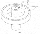
- Fig.2 shows a schematic view of a wireless power transmission device according to a first embodiment of the present disclosure.
- the wireless power transmission device mainly comprises a first coil 11 and a second coil 21 electromagnetically coupled with the first coil 11 without contacting therewith.
- One of the first coil 11 and the second coil 21 is a transmitting coil, and the other is a receiving coil.
- the first coil 11 is a spiral coil defining a hollow annular space internally.
- a central axis of the first coil 11 passes through the annular space, and the second coil 21 passes through the first coil 11 via the annular space.
- a central axis of the second coil 21 is coincident with that of the first coil 11. That is, the second coil 21 has the same central axis as the first coil 11. It should be noted that the present disclosure is not limited to the illustrated embodiment. Alternatively, the central axis of the first coil 11 may not be coincident with or parallel to that of the second coil 21. In another embodiment, for example, the central axis of the first coil 11 may be perpendicular to or angled with that of the second coil 21. For example, an angle between the central axes of the first and second coils 11 and 12 may be greater than 0 degree and less than 90 degrees.
- the angle may be greater than 0 degree and less than 30 degrees, and more preferably, the angle may be greater than 0 degree and less than 15 degrees. More preferably, the angle may be greater than 0 degree and less than 10 degrees, and more preferably, the angle may be greater than 0 degree and less than 5 degrees.
- a first magnetic core 12 is provided outside the first coil 11. That is, the first magnetic core 12 is arranged to surround an outer circumferential surface of the first coil 11. The first coil 11 and the first magnetic core 12 together form a first coil assembly 10.
- a second magnetic core 22 is provided inside the second coil 21. That is, the second coil 21 is arranged to surround an outer circumferential surface of the second magnetic core 22, in other words, the second coil 21 is wound around the second magnetic core 22.
- the second coil 21 and the second magnetic core 22 together form a second coil assembly 20.
- the second coil assembly 20 passes through the first coil assembly 10 via the annular space defined by the first coil 11 without contacting therewith.
- the first coil 11 is rotatable around its central axis
- the second coil 21 is movable in a direction along its central axis.
- the first coil 11 and the second coil 21 may be spiral coil windings, for example, spiral coil windings formed on the first and second coils on the first and second magnetic cores respectively.
- the first magnetic core 12 and the second magnetic core 22 may be made of a soft magnetic material such as ferrite material or plasto-ferrite material.
- the first magnetic core 12 and the second magnetic core 22 may be made of a conventional ferrite material such as Mn-Zn oxide ferrite material or Ni-Zn oxide ferrite material.
- the Mn-Zn oxide ferrite material and the Ni-Zn oxide ferrite material have disadvantages that they cannot be injection molded into a complex shape and have a large weight.
- a new type of plasto-ferrite material having a low initial permeability (typically 5-20), light weight, and can be easily injection molded into a variety of complex shapes has appeared in recent years.
- the first magnetic core 12 and the second magnetic core 22 may be made of plasto-ferrite material.
- the plasto-ferrite material herein includes any ferrite material having plasticity that is commercially available through a legitimate commercial route.
- the first coil 11 and the first magnetic core 12 are formed as a hollow cylindrical shape
- the second coil 21 is formed as a hollow cylindrical shape
- the second magnetic core 22 is formed as a solid cylindrical shape.
- first coil 11 and the first magnetic core 12 may be formed as a hollow prismatic shape, pyramidal shape or other suitable shapes.
- the second coil 21 may be formed as a hollow prismatic shape, pyramidal shape or other suitable shapes, and the second magnetic core 22 may be formed as a solid prismatic shape, pyramidal shape or other suitable shapes.
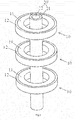
- Fig.3 shows a schematic view of a wireless power transmission device according to a second embodiment of the present disclosure.
- the wireless power transmission device according to the second embodiment shown in Fig.3 differs from that according to the first embodiment shown in Fig.2 in that: the wireless power transmission device according to the first embodiment shown in Fig.2 comprises only one first coil assembly 10, while the wireless power transmission device according to the second embodiment shown in Fig.3 comprises a plurality of first coil assemblies 10.
- the wireless power transmission device comprises a plurality of first coil assemblies 10 and a second coil assembly 20.
- the second coil assembly 20 passes through the plurality of first coil assemblies 10 via an annular space defined by each of the first coils 11 of the plurality of first coil assemblies 10 respectively without contacting with each first coil assembly 10.
- the second coil assembly 20 has a long length along its central axis so as to pass through the plurality of first coil assemblies 10.
- central axes of a plurality of first coils 11 is coincident with a central axis of the second coil 21. That is, the plurality of first coils 11 have the same central axis as the second coil 21.
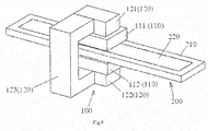
- Fig.4 shows a schematic view of a wireless power transmission device according to a third embodiment of the present disclosure.
- the wireless power transmission device mainly comprises a first coil 110 and a second coil 210 electromagnetically coupled to the first coil 110 without contacting therewith.
- One of the first coil 110 and the second coil 210 is a transmitting coil, and the other is a receiving coil.
- the first coil 110 includes a first portion 111 and a second portion 112 opposite to the first portion 111.
- the first portion 111 and the second portion 112 of the first coil 110 are spaced apart from each other.
- the first portion 111 and the second portion 112 of the first coil 110 are formed by winding the same wire.
- a space is defined between the first portion 111 and the second portion 112 of the first coil 110.
- a central axis of the first coil 110 passes through the space, and the second coil 210 passes between the first portion 111 and the second portion 112 of the first coil 110 via the space.
- a central axis of the second coil 210 is parallel to that of the first coil 110. However, it is not necessary that the central axis of the second coil 210 is coincident with that of the first coil 110. It should be noted that the present disclosure is not limited to the illustrated embodiment. Alternatively, the central axis of the first coil 110 may be perpendicular to or angled with that of the second coil 210. For example, an angle formed between the central axes of the first and second coils 110 and 210 may be greater than 0 degree and less than 90 degrees. In an exemplary embodiment of the present invention, the angle may be greater than 0 degree and less than 30 degrees.
- the angle may be greater than 0 degree and less than 15 degrees. In an exemplary embodiment of the present invention, the angle may be greater than 0 degree and less than 10 degrees. In an exemplary embodiment of the present invention, the angle may be greater than 0 degree and less than 5 degrees.
- the first coil 110 is provided with a first magnetic core 120
- the second coil 210 is provided with a second magnetic core 220.
- the first magnetic core 120 comprises a U-shaped body portion 123, a first block 121 connected to a side (upper side in Fig.4 ) of the U-shaped body portion 123 at an opening thereof, and a second block 122 connected to the other side (lower side in Fig.4 ) of the U-shaped body portion 123 at the opening thereof
- the first portion 111 of the first coil 110 is wound around the first block 121 of the first magnetic core 120
- the second portion 112 of the first coil 110 is wound around the second block 122 of the first magnetic core 120. In this way, the first coil 110 and the first magnetic core 120 together form a first coil assembly 100.
- the second magnetic core 220 has an elongated rectangular parallelepiped shape, and the second coil 210 is wound around an outer periphery of the second magnetic core 220. In this way, the second coil 210 and the second magnetic core 220 together form a second coil assembly 200.
- the second coil assembly 200 passes through the first coil assembly 100 via the space between the first portion 111 and the second portion 112 of the first coil 110 without contacting therewith.
- the first magnetic core 120 and the second magnetic core 220 may be made of a soft magnetic material such as a ferrite or plasto-ferrite material.
- the first magnetic core 120 and the second magnetic core 220 may be made of a conventional ferrite material such as Mn-Zn oxide ferrite material or Ni-Zn oxide ferrite material.
- the Mn-Zn oxide ferrite material and the Ni-Zn oxide ferrite material have disadvantages that they cannot be injection molded into a complex shape and have a large weight.
- a new type of plasto-ferrite material having a low initial permeability (typically 5-20), light weight, and can be easily injection molded into a variety of complex shapes has appeared in recent years.
- the first magnetic core 120 and the second magnetic core 220 may be made of plasto-ferrite material.
- the plasto-ferrite material herein includes any ferrite material having plasticity that is commercially available through a legitimate commercial route.
- first magnetic core 120 and the second magnetic core 220 have substantially rectangular cross sections.
- the present disclosure is not limited to the illustrated embodiment.
- the cross section of each of the first magnetic core 120 and the second magnetic core 220 may have a circular, oval, triangular, trapezoidal, square shape or other suitable shapes.
- Fig.5 shows a schematic view of a wireless power transmission device according to a fourth embodiment of the present disclosure.
- the wireless power transmission device according to the fourth embodiment shown in Fig.5 differs from that according to the third embodiment shown in Fig.4 in that: the wireless power transmission device according to the third embodiment shown in Fig.4 comprises only one first coil assembly 100, while the wireless power transmission device according to the fourth embodiment shown in Fig.5 comprises a plurality of first coil assemblies 100.
- the wireless power transmission device comprises a plurality of first coil assemblies 100 and a second coil assembly 200.
- the second coil assembly 200 passes through the plurality of first coil assemblies 100 via a space defined by the first portion 111 and the second portion 112 of each of the first coils 110 of the plurality of first coil assemblies 100 respectively without contacting with each first coil assembly 100.
- the second coil assembly 200 has a long length in a direction perpendicular to its central axis so as to pass through the plurality of first coil assemblies 100.
- the central axes of the plurality of first coils 110 are positioned in the same plane as that of the second coil 210.
Landscapes
- Engineering & Computer Science (AREA)
- Power Engineering (AREA)
- Chemical & Material Sciences (AREA)
- Dispersion Chemistry (AREA)
- Computer Networks & Wireless Communication (AREA)
- Charge And Discharge Circuits For Batteries Or The Like (AREA)
Abstract
Description
- The present disclosure relates to a wireless power transmission device adapted to wirelessly transmit a power through an electromagnetic coupling.
- In an electronic and electrical apparatus, an electric power required by control components and drive components is obtained mainly through external wirings or built-in batteries. The electric power is mainly transmitted by means of a physical connection through power lines in the apparatus. Therefore, physical wear is prone to occur in some regions where moving parts are located, thereby resulting in some security, lifetime and maintenance issues. As a result, a wireless electrical energy transmission is introduced into the design of the electronic and electrical apparatus, i.e., a coil assembly coupling is used in some key parts so as to achieve non-contact energy transmission, as shown in
Fig.1 . -
Fig.1 shows a conventional wireless power transmission device. The wireless power transmission device comprises a first spiral coil 1 (e.g., a transmitting coil) received in a first housing 3 and a second spiral coil 2 (e.g., a receiving coil) received in asecond housing 4. The firstspiral coil 1 and the second spiral coil 2 are separated from each other by a predetermined distance in a direction along their central axes. Ends of the two coils are parallel to each other. Spaces formed by the two coils respectively are disjoint and independent from each other. The two coils are electromagnetically coupled with each other, so that electric power is wirelessly transmitted between the firstspiral coil 1 and the second spiral coil 2. - However, during an actual design process for the wireless power transmission, such a coil cooperating structure brings some difficulties for certain performances. For example, it is sometimes required that the power receiving coil mounted in the moving parts needs to maintain some electric characteristics, such as a constant voltage, current, power or the like within a certain motion range. However, it is very difficult for the separated coupling manner shown in
Fig.1 to achieve this effect. Also, since the two coils are separated and independent from each other over spatially coupling distance, a coupling strength thereof is small, and an effective coupling distance is very short, typically less than 10mm. In order to obtain stronger electromagnetic coupling and longer coupling distance, it is necessary to increase a diameter and a thickness of the coils, thereby resulting in an excessive size thereof. - The present disclosure is intended to solve at least one aspect of the above-mentioned problems and drawbacks existed in the prior art.
- In order to meet the requirements of small size, strong coupling and constant coupling within a certain motion range, the inventor of the present disclosure provides a new solution in which a transmitting coil and a receiving coil of key parts cooperate with each other by means of a special cooperation manner.
- Through research, the inventor of the present disclosure have found that a strong electromagnetic coupling may be obtained if the transmitting coil and the receiving coil cooperate with each other in a nested-fit manner, so that an efficient transmission power from the transmitting coil to the receiving coil can be ensured. The nested-fit manner herein means that: at least a portion of one of the transmitting coil and the receiving coil passes through at least a portion of a space defined by the other of the transmitting coil and the receiving coil, the two nested coils are not in contact with each other, but spaces defined by the two coils respectively are at least partially overlapped with each other, and axes of the two coils may be parallel to, perpendicular to each other or intersect with each other at any other angles. Also, the nested-fit manner between the two coils can be easily extended to the nested-fit between a plurality of coils.
- The present disclosure provides a wireless power transmission device having coils of small sizes, a strong electromagnetic coupling between the coils and a substantially constant strength of electromagnetic coupling between the coils within a certain motion range.
- According to an aspect of the present disclosure, there is provided a wireless power transmission device comprising a first coil and a second coil electromagnetically coupled to the first coil without contacting therewith, wherein at least a portion of one of the first coil and the second coil passes through at least a portion of a space defined by the other of the first coil and the second coil.
- According to an exemplary embodiment of the present disclosure, the first coil defines a space through which a central axis of the first coil passes, and the second coil passes through the first coil via the space.
- According to another embodiment of the present disclosure, the central axis of the first coil is parallel to a central axis of the second coil.
- According to further another embodiment of the present disclosure, the central axis of the first coil is perpendicular to a central axis of the second coil.
- According to yet another embodiment of the present disclosure, the central axis of the first coil is angled with a central axis of the second coil.
- According to still another embodiment of the present disclosure, the wireless power transmission device further comprises a first magnetic core disposed inside or outside the first coil and forming a first coil assembly together with the first coil and a second magnetic core disposed inside or outside the second coil and forming a second coil assembly together with the second coil, wherein the second coil assembly passes through the first coil assembly via the space without contacting therewith.
- According to further another embodiment of the present disclosure, the space is an annular space surrounded by the first coil.
- According to yet another embodiment of the present disclosure, the central axis of the first coil is coincident with that of the second coil.
- According to still another embodiment of the present disclosure, the first magnetic core is arranged to surround an outer periphery of the first coil, and the second coil is arranged to surround an outer periphery of the second magnetic core.
- According to further another embodiment of the present disclosure, the first coil is rotatable around its central axis, and the second coil is movable in a direction along its central axis.
- According to yet another embodiment of the present disclosure, the first coil and the second coil are spiral coil windings, first and second spiral coil windings formed on the first magnetic and second cores respectively, for example.
- According to still another embodiment of the present disclosure, the first magnetic core and the second magnetic core are made of a soft magnetic material such as a ferrite or plasto-ferrite material.
- According to further another embodiment of the present disclosure, the first magnetic core and the second magnetic core are made of Mn-Zn oxide ferrite material or Ni-Zn oxide ferrite material. The present disclosure, however, is not limited to use the two ferrite magnetic cores, and other suitable ferrite magnetic cores may also be used.
- According to yet another embodiment of the present disclosure, the first coil and the first magnetic core are formed as a hollow cylindrical shape, and the second coil is formed as a hollow cylindrical shape, and the second magnetic core is formed as a solid cylindrical shape.
- According to still another embodiment of the present disclosure, both the first and second magnetic cores are made of a plasto-ferrite material.
- According to further another embodiment of the present disclosure, the first coil and the first magnetic core are formed as a hollow cylindrical, prismatic or pyramidal shape, the second coil is formed as a hollow cylindrical, prismatic or pyramidal shape, and the second magnetic core is formed as a solid cylindrical, prismatic or pyramidal shape. The first and second coils and the first and second magnetic cores, however, are not limited to the above shapes, and other suitable shapes may also be used.
- According to yet another embodiment of the present disclosure, the wireless power transmission device comprises a plurality of first coil assemblies and a second coil assembly. The second coil assembly passes through the plurality of first coil assemblies via the space without contacting with each first coil assembly.
- According to still another embodiment of the present disclosure, the first coil comprises a first portion and a second portion opposite to the first portion. The space is a space defined between the first portion and the second portion of the first coil.
- According to further another embodiment of the present disclosure, the first magnetic core comprises a U-shaped body portion, a first block connected to a side of the U-shaped body portion at an opening thereof, and a second block connected to the other side of the U-shaped body portion at the opening thereof.
- According to yet another embodiment of the present disclosure, the first portion of the first coil is wound around the first block of the first magnetic core, and the second portion of the first coil is wound around the second block of the first magnetic core.
- According to still another embodiment of the present disclosure, the second magnetic core has an elongated rectangular parallelepiped shape, and the second coil is wound around an outer periphery of the second magnetic core.
- According to further another embodiment of the present disclosure, the first magnetic core and the second magnetic core are made of a soft magnetic material such as a ferrite or plasto-ferrite material.
- According to yet another embodiment of the present disclosure, the first and second magnetic cores are made of Mn-Zn oxide ferrite material or Ni-Zn oxide ferrite material.
- According to still another embodiment of the present disclosure, the first and second magnetic cores are made of a plasto-ferrite material.
- According to further another embodiment of the present disclosure, each of the first magnetic core and the second magnetic core has a circular, oval, triangular, trapezoidal, rectangular or square cross section.
- According to yet another embodiment of the present disclosure, the wireless power transmission device comprises a plurality of first coil assemblies and a second coil assembly. The second coil assembly passes through the plurality of first coil assemblies via the space without contacting with each first coil assembly.
- In the wireless power transmission device according to various embodiments of the present disclosure, since one of a transmitting coil and a receiving coil passes through the other of the transmitting coil and the receiving coil, strength of electromagnetic coupling between the two coils can be improved so as to increase the strength of electromagnetic coupling between the coils without increasing sizes thereof.
- Other objectives and advantages of the present disclosure will become more apparent by describing the present disclosure with reference to the following accompanying drawings, and this description may also aid to give a complete comprehension of the present disclosure.
-
-
Fig.1 shows a schematic view of an electromagnetic coupling device in the prior art; -
Fig.2 shows a schematic view of a wireless power transmission device according to a first embodiment of the present disclosure; -
Fig.3 shows a schematic view of a wireless power transmission device according to a second embodiment of the present disclosure; -
Fig.4 shows a schematic view of a wireless power transmission device according to a third embodiment of the present disclosure; -
Fig.5 shows a schematic view of a wireless power transmission device according to a fourth embodiment of the present disclosure. - The technical solutions of the disclosure will be described hereinafter in detail in exemplary embodiments with reference to the attached drawings. In the description, the same or similar reference numerals refer to the same or similar components. The description to the embodiments of the disclosure hereinafter with reference to the attached drawings is intended to explain the general inventive idea of the invention and should not be construed as being limitative to the disclosure.
- In addition, in the below detail description, for easy to explain, many specific details are set forth to provide a complete understanding to the disclosure. However, one or more embodiments can be obviously carried out without these specific details. In other cases, well-known structures and devices are illustrated to simplify the drawings.
- According to a general inventive concept, there is provided a wireless power transmission device comprising a
first coil 11 and asecond coil 21 electromagnetically coupled to the first coil without contacting therewith, wherein at least a portion of one of thefirst coil 11 and thesecond coil 12 passes through at least a portion of a space defined by the other of thefirst coil 11 and thesecond coil 12. -
Fig.2 shows a schematic view of a wireless power transmission device according to a first embodiment of the present disclosure. - As shown in
Fig.2 , the wireless power transmission device mainly comprises afirst coil 11 and asecond coil 21 electromagnetically coupled with thefirst coil 11 without contacting therewith. One of thefirst coil 11 and thesecond coil 21 is a transmitting coil, and the other is a receiving coil. - With continued reference to
Fig.2 , thefirst coil 11 is a spiral coil defining a hollow annular space internally. A central axis of thefirst coil 11 passes through the annular space, and thesecond coil 21 passes through thefirst coil 11 via the annular space. - In the embodiment illustrated in
Fig.2 , a central axis of thesecond coil 21 is coincident with that of thefirst coil 11. That is, thesecond coil 21 has the same central axis as thefirst coil 11. It should be noted that the present disclosure is not limited to the illustrated embodiment. Alternatively, the central axis of thefirst coil 11 may not be coincident with or parallel to that of thesecond coil 21. In another embodiment, for example, the central axis of thefirst coil 11 may be perpendicular to or angled with that of thesecond coil 21. For example, an angle between the central axes of the first andsecond coils - In order to improve an electromagnetic coupling between the
first coil 11 and thesecond coil 21, as shown inFig.2 , a firstmagnetic core 12 is provided outside thefirst coil 11. That is, the firstmagnetic core 12 is arranged to surround an outer circumferential surface of thefirst coil 11. Thefirst coil 11 and the firstmagnetic core 12 together form afirst coil assembly 10. - As shown in
Fig.2 , a secondmagnetic core 22 is provided inside thesecond coil 21. That is, thesecond coil 21 is arranged to surround an outer circumferential surface of the secondmagnetic core 22, in other words, thesecond coil 21 is wound around the secondmagnetic core 22. Thesecond coil 21 and the secondmagnetic core 22 together form asecond coil assembly 20. - As shown in
Fig.2 , thesecond coil assembly 20 passes through thefirst coil assembly 10 via the annular space defined by thefirst coil 11 without contacting therewith. - In the embodiment shown in
Fig.2 , thefirst coil 11 is rotatable around its central axis, and thesecond coil 21 is movable in a direction along its central axis. - In an embodiment of the present disclosure, as shown in
Fig.2 , thefirst coil 11 and thesecond coil 21 may be spiral coil windings, for example, spiral coil windings formed on the first and second coils on the first and second magnetic cores respectively. - In an embodiment of the present disclosure, the first
magnetic core 12 and the secondmagnetic core 22 may be made of a soft magnetic material such as ferrite material or plasto-ferrite material. - In an embodiment of the present disclosure, since a strength of coupling between the transmitting coil and the receiving coil is essential for efficient power transmission, in order to generate sufficient electromagnetic coupling between coils of small size, in an embodiment of the present disclosure, the first
magnetic core 12 and the secondmagnetic core 22 may be made of a conventional ferrite material such as Mn-Zn oxide ferrite material or Ni-Zn oxide ferrite material. - However, the Mn-Zn oxide ferrite material and the Ni-Zn oxide ferrite material have disadvantages that they cannot be injection molded into a complex shape and have a large weight. In order to overcome these disadvantages of the Mn-Zn oxide ferrite material and the Ni-Zn oxide ferrite material, a new type of plasto-ferrite material having a low initial permeability (typically 5-20), light weight, and can be easily injection molded into a variety of complex shapes has appeared in recent years. Thus, in another embodiment of the present disclosure, the first
magnetic core 12 and the secondmagnetic core 22 may be made of plasto-ferrite material. The plasto-ferrite material herein includes any ferrite material having plasticity that is commercially available through a legitimate commercial route. - As shown in
Fig.2 , thefirst coil 11 and the firstmagnetic core 12 are formed as a hollow cylindrical shape, thesecond coil 21 is formed as a hollow cylindrical shape, and the secondmagnetic core 22 is formed as a solid cylindrical shape. - However, the present disclosure is not limited to the illustrated embodiment. Alternatively, the
first coil 11 and the firstmagnetic core 12 may be formed as a hollow prismatic shape, pyramidal shape or other suitable shapes. Further, thesecond coil 21 may be formed as a hollow prismatic shape, pyramidal shape or other suitable shapes, and the secondmagnetic core 22 may be formed as a solid prismatic shape, pyramidal shape or other suitable shapes. -
Fig.3 shows a schematic view of a wireless power transmission device according to a second embodiment of the present disclosure. - The wireless power transmission device according to the second embodiment shown in
Fig.3 differs from that according to the first embodiment shown inFig.2 in that: the wireless power transmission device according to the first embodiment shown inFig.2 comprises only onefirst coil assembly 10, while the wireless power transmission device according to the second embodiment shown inFig.3 comprises a plurality offirst coil assemblies 10. - As shown in
Fig.3 , the wireless power transmission device comprises a plurality offirst coil assemblies 10 and asecond coil assembly 20. Thesecond coil assembly 20 passes through the plurality offirst coil assemblies 10 via an annular space defined by each of thefirst coils 11 of the plurality offirst coil assemblies 10 respectively without contacting with eachfirst coil assembly 10. - It should be noted that, in the embodiment shown in
Fig.3 , thesecond coil assembly 20 has a long length along its central axis so as to pass through the plurality offirst coil assemblies 10. - In the embodiment shown in
Fig.3 , central axes of a plurality offirst coils 11 is coincident with a central axis of thesecond coil 21. That is, the plurality offirst coils 11 have the same central axis as thesecond coil 21. -
Fig.4 shows a schematic view of a wireless power transmission device according to a third embodiment of the present disclosure. - As shown in
Fig.4 , the wireless power transmission device mainly comprises afirst coil 110 and asecond coil 210 electromagnetically coupled to thefirst coil 110 without contacting therewith. One of thefirst coil 110 and thesecond coil 210 is a transmitting coil, and the other is a receiving coil. - With Continued reference to
Fig.4 , thefirst coil 110 includes afirst portion 111 and asecond portion 112 opposite to thefirst portion 111. Thefirst portion 111 and thesecond portion 112 of thefirst coil 110 are spaced apart from each other. However, it should be noted that thefirst portion 111 and thesecond portion 112 of thefirst coil 110 are formed by winding the same wire. - As shown in
Fig.4 , a space is defined between thefirst portion 111 and thesecond portion 112 of thefirst coil 110. A central axis of thefirst coil 110 passes through the space, and thesecond coil 210 passes between thefirst portion 111 and thesecond portion 112 of thefirst coil 110 via the space. - In the embodiment shown in
Fig.4 , a central axis of thesecond coil 210 is parallel to that of thefirst coil 110. However, it is not necessary that the central axis of thesecond coil 210 is coincident with that of thefirst coil 110. It should be noted that the present disclosure is not limited to the illustrated embodiment. Alternatively, the central axis of thefirst coil 110 may be perpendicular to or angled with that of thesecond coil 210. For example, an angle formed between the central axes of the first andsecond coils - In order to improve an electromagnetic coupling between the
first coil 110 and thesecond coil 210, as shown inFig.4 , thefirst coil 110 is provided with a firstmagnetic core 120, and thesecond coil 210 is provided with a secondmagnetic core 220. - As shown in
Fig.4 , in the illustrated embodiment, the firstmagnetic core 120 comprises aU-shaped body portion 123, afirst block 121 connected to a side (upper side inFig.4 ) of theU-shaped body portion 123 at an opening thereof, and a second block 122 connected to the other side (lower side inFig.4 ) of theU-shaped body portion 123 at the opening thereof Thefirst portion 111 of thefirst coil 110 is wound around thefirst block 121 of the firstmagnetic core 120, and thesecond portion 112 of thefirst coil 110 is wound around the second block 122 of the firstmagnetic core 120. In this way, thefirst coil 110 and the firstmagnetic core 120 together form afirst coil assembly 100. - With Continued reference to
Fig.4 , the secondmagnetic core 220 has an elongated rectangular parallelepiped shape, and thesecond coil 210 is wound around an outer periphery of the secondmagnetic core 220. In this way, thesecond coil 210 and the secondmagnetic core 220 together form asecond coil assembly 200. - As shown in
Fig.4 , thesecond coil assembly 200 passes through thefirst coil assembly 100 via the space between thefirst portion 111 and thesecond portion 112 of thefirst coil 110 without contacting therewith. - In an embodiment of the present disclosure, the first
magnetic core 120 and the secondmagnetic core 220 may be made of a soft magnetic material such as a ferrite or plasto-ferrite material. - In an embodiment of the present disclosure, since a strength of coupling between the transmitting coil and the receiving coil is essential for efficient power transmission, in order to generate sufficient electromagnetic coupling between coils of small size, in an embodiment of the present disclosure, the first
magnetic core 120 and the secondmagnetic core 220 may be made of a conventional ferrite material such as Mn-Zn oxide ferrite material or Ni-Zn oxide ferrite material. - However, the Mn-Zn oxide ferrite material and the Ni-Zn oxide ferrite material have disadvantages that they cannot be injection molded into a complex shape and have a large weight. In order to overcome these disadvantages of the Mn-Zn oxide ferrite material and the Ni-Zn oxide ferrite material, a new type of plasto-ferrite material having a low initial permeability (typically 5-20), light weight, and can be easily injection molded into a variety of complex shapes has appeared in recent years. Thus, in another embodiment of the present disclosure, the first
magnetic core 120 and the secondmagnetic core 220 may be made of plasto-ferrite material. The plasto-ferrite material herein includes any ferrite material having plasticity that is commercially available through a legitimate commercial route. - In the embodiment shown in
Fig.4 , the firstmagnetic core 120 and the secondmagnetic core 220 have substantially rectangular cross sections. However, the present disclosure is not limited to the illustrated embodiment. In another embodiment of the present disclosure, the cross section of each of the firstmagnetic core 120 and the secondmagnetic core 220 may have a circular, oval, triangular, trapezoidal, square shape or other suitable shapes. -
Fig.5 shows a schematic view of a wireless power transmission device according to a fourth embodiment of the present disclosure. - The wireless power transmission device according to the fourth embodiment shown in
Fig.5 differs from that according to the third embodiment shown inFig.4 in that: the wireless power transmission device according to the third embodiment shown inFig.4 comprises only onefirst coil assembly 100, while the wireless power transmission device according to the fourth embodiment shown inFig.5 comprises a plurality offirst coil assemblies 100. - As shown in
Fig.5 , the wireless power transmission device comprises a plurality offirst coil assemblies 100 and asecond coil assembly 200. Thesecond coil assembly 200 passes through the plurality offirst coil assemblies 100 via a space defined by thefirst portion 111 and thesecond portion 112 of each of thefirst coils 110 of the plurality offirst coil assemblies 100 respectively without contacting with eachfirst coil assembly 100. - It should be noted that, in the embodiment shown in
Fig.5 , thesecond coil assembly 200 has a long length in a direction perpendicular to its central axis so as to pass through the plurality offirst coil assemblies 100. - In the embodiment shown in
Fig.5 , the central axes of the plurality offirst coils 110 are positioned in the same plane as that of thesecond coil 210. - It should be appreciated for those skilled in the art that all the above embodiments are illustrative. Also, many modifications may be made to the above embodiments by those skilled in the art, and various structures described in various embodiments may be freely combined with each other without conflicting in configuration or principle.
- Though the present invention is described with reference to the accompanying drawings, the disclosed embodiments with reference to the drawings intend to make an exemplary illustration to the implementations of the present invention, but cannot be interpreted as a limitation to the present invention.
- Though some embodiments of the general inventive concept have been shown and explained, it should be understood by those skilled in the art that these embodiments may be modified without departing from the principle and spirit of the general inventive concept, and the scope of the present invention is defined by the claims and equivalents thereof.
- It should be noted that, the terms "comprising", "comprise", "including" and "include" should be understood as not excluding other elements or steps, the word "a" or "an" should be understood as not excluding plural of said elements or steps. In addition, any reference number in the claims should not be understood as limiting the scope of the present invention.
Claims (25)
- A wireless power transmission device comprising:a first coil (11); anda second coil (21) electromagnetically coupled with the first coil without contacting therewith,wherein at least a portion of one of the first coil (11) and the second coil (12) passes through at least a portion of a space defined by the other of the first coil (11) and the second coil (12).
- The wireless power transmission device according to claim 1, wherein
the first coil (11) defines a space through which a central axis of the first coil (11) passes; and
the second coil (21) passes through the first coil (11) via the space. - The wireless power transmission device according to claim 2, wherein
the central axis of the first coil (11) is parallel to a central axis of the second coil (21). - The wireless power transmission device according to claim 2, wherein
the central axis of the first coil (11) is perpendicular to a central axis of the second coil (21). - The wireless power transmission device according to claim 2, wherein
the central axis of the first coil (11) is angled with a central axis of the second coil (21). - The wireless power transmission device according to claim 2, further comprising:a first magnetic core (12) disposed inside or outside the first coil (11) and forming a first coil assembly (10) together with the first coil (11); anda second magnetic core (22) disposed inside or outside the second coil (21)and forming a second coil assembly (20) together with the second coil (21),wherein the second coil assembly (20) passes through the first coil assembly (10) via the space without contacting therewith.
- The wireless power transmission device according to claim 6, wherein the space is an annular space surrounded by the first coil (11).
- The wireless power transmission device according to claim 7, wherein the central axis of the first coil (11) is coincident with a central axis of the second coil (21).
- The wireless power transmission device according to claim 8, wherein
the first magnetic core (12) is arranged to surround an outer periphery of the first coil (11); and
the second coil (21) is arranged to surround an outer periphery of the second magnetic core (22). - The wireless power transmission device according to claim 9, wherein
the first coil (11) is rotatable around its central axis, and the second coil (21) is movable in a direction along its central axis.. - The wireless power transmission device according to claim 6, wherein
the first coil (11) and the second coil (21) are spiral coil windings formed on the first magnetic core (12) and the second magnetic core (22), respectively. - The wireless power transmission device according to claim 11, wherein
the first magnetic core and the second magnetic core are made of a soft magnetic material. - The wireless power transmission device according to claim 12, wherein
the first magnetic core and the second magnetic core are made of a ferrite material or a plasto-ferrite material. - The wireless power transmission device according to claim 12, wherein
the first magnetic core (12) and the second magnetic core (22) are made of Mn-Zn oxide ferrite material or Ni-Zn oxide ferrite material. - The wireless power transmission device according to claim 14, wherein
the first coil (11) and the first magnetic core (12) are formed as a hollow cylindrical, prismatic or pyramidal shape; and
the second coil (21) is formed as a hollow cylindrical, prismatic or pyramidal shape, and the second magnetic core (22) is formed as a solid cylindrical, prismatic or pyramidal shape. - The wireless power transmission device according to any one of claims 7-15, wherein
the wireless power transmission device comprises a plurality of first coil assemblies (10) and a second coil assembly (20); and
the second coil assembly (20) passes through the plurality of first coil assemblies (10) via the space without contacting with each first coil assembly (10). - The wireless power transmission device according to claim 6, wherein
the first coil (110) comprises a first portion (111) and a second portion (112) opposite to the first portion (111); and
the space is a space defined between the first portion (111) and the second portion (112) of the first coil (110). - The wireless power transmission device according to claim 17, wherein the first magnetic core (120) comprises:a U-shaped body portion (123);a first block (121) connected to a side of the U-shaped body portion (123) at an opening thereof; anda second block (122) connected to the other side of the U-shaped body portion (123) at the opening thereof.
- The wireless power transmission device according to claim 18, wherein
the first portion (111) of the first coil (110) is wound around the first block (121) of the first magnetic core (120), and
the second portion (112) of the first coil (110) is wound around the second block (122) of the first magnetic core (120). - The wireless power transmission device according to claim 19, wherein
the second magnetic core (220) has an elongated rectangular parallelepiped shape, and the second coil (210) is wound around an outer periphery of the second magnetic core (220). - The wireless power transmission device according to claim 20, wherein
the first magnetic core (120) and the second magnetic core (220) are made of a soft magnetic material. - The wireless power transmission device according to claim 21, wherein
the first magnetic core (120) and the second magnetic core (220) are made of a ferrite or plasto-ferrite material. - The wireless power transmission device according to claim 22, wherein
the first magnetic core (120) and the second magnetic core (220) are made of Mn-Zn oxide ferrite material or Ni-Zn oxide ferrite material. - The wireless power transmission device according to claim 22, wherein
each of the first magnetic core (120) and the second magnetic core (220) has a circular, oval, triangular, trapezoidal, rectangular or square cross section. - The wireless power transmission device according to any one of claims 17-24, wherein
the wireless power transmission device comprises a plurality of first coil assemblies (100) and a second coil assembly (200); and
the second coil assembly (200) passes through the plurality of first coil assemblies (100) via the space without contacting with each first coil assembly (100).
Applications Claiming Priority (2)
| Application Number | Priority Date | Filing Date | Title |
|---|---|---|---|
| CN201410208565.9A CN105098998B (en) | 2014-05-16 | 2014-05-16 | Wireless power transmission device |
| PCT/CN2015/078177 WO2015172665A1 (en) | 2014-05-16 | 2015-05-04 | Wireless power transmission device |
Publications (3)
| Publication Number | Publication Date |
|---|---|
| EP3144954A1 true EP3144954A1 (en) | 2017-03-22 |
| EP3144954A4 EP3144954A4 (en) | 2018-01-03 |
| EP3144954B1 EP3144954B1 (en) | 2020-09-16 |
Family
ID=54479315
Family Applications (1)
| Application Number | Title | Priority Date | Filing Date |
|---|---|---|---|
| EP15791920.0A Active EP3144954B1 (en) | 2014-05-16 | 2015-05-04 | Wireless power transmission device |
Country Status (6)
| Country | Link |
|---|---|
| US (1) | US11094456B2 (en) |
| EP (1) | EP3144954B1 (en) |
| KR (1) | KR101923565B1 (en) |
| CN (1) | CN105098998B (en) |
| MX (1) | MX362878B (en) |
| WO (1) | WO2015172665A1 (en) |
Cited By (3)
| Publication number | Priority date | Publication date | Assignee | Title |
|---|---|---|---|---|
| WO2017175113A1 (en) * | 2016-04-08 | 2017-10-12 | Tyco Electronics (Shanghai) Co. Ltd. | Wireless powering device and electrical apparatus |
| EP3504722A1 (en) * | 2016-08-24 | 2019-07-03 | Tyco Electronics (Shanghai) Co., Ltd. | Wireless power supply device and electrical apparatus |
| US11677573B2 (en) | 2018-08-24 | 2023-06-13 | Phoenix Contact Gmbh & Co. Kg | Contactless PoE connector and contactless PoE connection system |
Families Citing this family (20)
| Publication number | Priority date | Publication date | Assignee | Title |
|---|---|---|---|---|
| CN205141843U (en) * | 2015-10-26 | 2016-04-06 | 泰科电子(上海)有限公司 | Wireless power transmission device and electrical equipment |
| CN106887906B (en) * | 2015-12-16 | 2024-06-18 | 泰科电子(上海)有限公司 | Wireless power supply device and electrical equipment |
| CN105761668B (en) * | 2016-04-25 | 2018-12-07 | 南京达斯琪数字科技有限公司 | A kind of rotary scanning LED display device |
| CN108143264A (en) * | 2016-12-02 | 2018-06-12 | 佛山市顺德区美的电热电器制造有限公司 | Split-type electric pressure cooker |
| CN108143262A (en) * | 2016-12-02 | 2018-06-12 | 佛山市顺德区美的电热电器制造有限公司 | Split-type electric pressure cooker |
| CN108143263A (en) * | 2016-12-02 | 2018-06-12 | 佛山市顺德区美的电热电器制造有限公司 | Split-type electric pressure cooker |
| CN108143256A (en) * | 2016-12-02 | 2018-06-12 | 佛山市顺德区美的电热电器制造有限公司 | Split-type electric pressure cooker |
| CN108878118B (en) | 2017-05-08 | 2021-06-11 | 台达电子工业股份有限公司 | Transformer device |
| CN108878105B (en) * | 2017-05-08 | 2021-07-30 | 台达电子工业股份有限公司 | transformer |
| CN107154680A (en) * | 2017-05-27 | 2017-09-12 | 山东大学 | A kind of coupling coil charged applied to underwater wireless and core structure and system |
| CN110138095B (en) * | 2018-02-09 | 2023-06-16 | 泰科电子(上海)有限公司 | Wireless power supply and electrical equipment |
| CN108597206A (en) * | 2018-06-06 | 2018-09-28 | 安徽启电自动化科技有限公司 | A kind of rotating environment electricity pick-up device |
| CN110676943B (en) | 2018-07-03 | 2025-06-24 | 泰科电子(上海)有限公司 | Electrical Equipment |
| CN111092493A (en) * | 2018-10-23 | 2020-05-01 | 泰科电子(上海)有限公司 | Wireless power supply device |
| CN111614168B (en) * | 2019-02-26 | 2024-03-15 | 泰科电子(上海)有限公司 | Wireless power supply device and electrical equipment |
| RU2719768C1 (en) | 2019-09-25 | 2020-04-23 | Самсунг Электроникс Ко., Лтд. | Multilayer inductance coil |
| US12142934B2 (en) | 2020-02-26 | 2024-11-12 | Ge Intellectual Property Licensing, Llc | Overlapping secondary coils in a wireless power reception apparatus |
| CN112104097B (en) * | 2020-11-18 | 2021-04-27 | 深圳赫兹创新技术有限公司 | A wireless charging coil assembly and wireless power transmission device |
| EP4356406A4 (en) * | 2021-06-16 | 2025-04-16 | Resonant Link, Inc. | HIGHLY EFFICIENT WIRELESS POWER TRANSMISSION COILS |
| CN114093619B (en) * | 2021-11-05 | 2023-10-13 | 哈尔滨工业大学 | Staggered U-shaped magnetic core and rail-type staggered U-shaped coupling structure wireless power supply system |
Family Cites Families (21)
| Publication number | Priority date | Publication date | Assignee | Title |
|---|---|---|---|---|
| JPH04326709A (en) * | 1991-04-26 | 1992-11-16 | Matsushita Electric Ind Co Ltd | Rotary transformer |
| DE9314433U1 (en) * | 1993-09-23 | 1994-01-05 | Siemens AG, 80333 München | System for contactless data or energy transmission |
| JPH10225021A (en) * | 1997-02-03 | 1998-08-21 | Sony Corp | Electromagnetic inductive coupling device and power supply device |
| JPH10322921A (en) * | 1997-05-15 | 1998-12-04 | Sumitomo Wiring Syst Ltd | Magnetic coupling device for electric vehicle charging |
| JP4064333B2 (en) * | 2003-10-31 | 2008-03-19 | 米沢電線株式会社 | Contactless rechargeable equipment and charger |
| JP4208757B2 (en) * | 2004-03-31 | 2009-01-14 | 株式会社椿本チエイン | Contactless power supply system |
| US7135949B2 (en) * | 2004-07-15 | 2006-11-14 | Tyco Electronics Corporation | Transformer or inductor containing a magnetic core having abbreviated sidewalls and an asymmetric center core portion |
| JP2006303221A (en) | 2005-04-21 | 2006-11-02 | Chikura Kogyo Kk | Non-contact power supply device and automatic door device using the same |
| CN1819397A (en) * | 2006-01-19 | 2006-08-16 | 重庆大学 | Non-contacting transmitter with freely rotary electric energy pick-up mechanism |
| DE102007015168A1 (en) * | 2007-03-27 | 2008-10-02 | Trithor Gmbh | Linear machine with a primary part and a secondary part |
| JP2009060762A (en) * | 2007-09-03 | 2009-03-19 | Panasonic Electric Works Co Ltd | Power supply device |
| CN101262149A (en) * | 2008-04-24 | 2008-09-10 | 上海交通大学 | Controllable high-efficiency wireless energy supply device for biological implants |
| JP4536131B2 (en) * | 2008-05-23 | 2010-09-01 | カワサキプラントシステムズ株式会社 | Insulated power feeder for moving objects |
| CN101478182B (en) * | 2009-01-23 | 2011-10-12 | 西安电子科技大学 | Non-contact type electric energy, data integrated sliding ring type transmission method |
| JP5689587B2 (en) | 2009-03-31 | 2015-03-25 | 富士通株式会社 | Power transmission equipment |
| CN101645617B (en) * | 2009-08-26 | 2011-12-07 | 中国海洋石油总公司 | Slip ring |
| CN201887566U (en) * | 2010-11-19 | 2011-06-29 | 昆盈企业股份有限公司 | Non-contact power supply device for computer input device |
| KR101213090B1 (en) * | 2011-07-14 | 2012-12-18 | 유한회사 한림포스텍 | Core assembly for wireless power transmission apparatus and wireless power transmission apparatus having the same |
| SG11201405961XA (en) * | 2012-03-28 | 2014-10-30 | Fujitsu Ltd | Wireless power transmission system and wireless power transmission method |
| CN103659791B (en) * | 2012-09-26 | 2016-03-02 | 电装波动株式会社 | Wireless power supply and possess the direct-driving type system of this device |
| JP6423142B2 (en) * | 2013-10-01 | 2018-11-14 | トヨタ自動車株式会社 | Power receiving device, power transmitting device and vehicle |
-
2014
- 2014-05-16 CN CN201410208565.9A patent/CN105098998B/en active Active
-
2015
- 2015-05-04 MX MX2016015073A patent/MX362878B/en active IP Right Grant
- 2015-05-04 KR KR1020167034663A patent/KR101923565B1/en active Active
- 2015-05-04 EP EP15791920.0A patent/EP3144954B1/en active Active
- 2015-05-04 WO PCT/CN2015/078177 patent/WO2015172665A1/en not_active Ceased
-
2016
- 2016-11-16 US US15/353,271 patent/US11094456B2/en active Active
Cited By (3)
| Publication number | Priority date | Publication date | Assignee | Title |
|---|---|---|---|---|
| WO2017175113A1 (en) * | 2016-04-08 | 2017-10-12 | Tyco Electronics (Shanghai) Co. Ltd. | Wireless powering device and electrical apparatus |
| EP3504722A1 (en) * | 2016-08-24 | 2019-07-03 | Tyco Electronics (Shanghai) Co., Ltd. | Wireless power supply device and electrical apparatus |
| US11677573B2 (en) | 2018-08-24 | 2023-06-13 | Phoenix Contact Gmbh & Co. Kg | Contactless PoE connector and contactless PoE connection system |
Also Published As
| Publication number | Publication date |
|---|---|
| CN105098998B (en) | 2020-02-11 |
| EP3144954B1 (en) | 2020-09-16 |
| US11094456B2 (en) | 2021-08-17 |
| MX2016015073A (en) | 2017-07-13 |
| KR20170003675A (en) | 2017-01-09 |
| KR101923565B1 (en) | 2018-11-29 |
| CN105098998A (en) | 2015-11-25 |
| MX362878B (en) | 2019-02-21 |
| EP3144954A4 (en) | 2018-01-03 |
| US20170069422A1 (en) | 2017-03-09 |
| WO2015172665A1 (en) | 2015-11-19 |
Similar Documents
| Publication | Publication Date | Title |
|---|---|---|
| EP3144954B1 (en) | Wireless power transmission device | |
| JP5822868B2 (en) | Inductive energy wireless transmission equipment | |
| EP2871712A1 (en) | Non-contact type power transmitting coil and non-contact type power supplying apparatus | |
| JP6524175B2 (en) | Power transfer mechanism | |
| JP6179160B2 (en) | Wireless power transmission equipment | |
| JP2012110080A5 (en) | ||
| US10504648B2 (en) | Antenna for wireless power transmission | |
| RU2016106629A (en) | ELECTRIC MACHINE | |
| CN106971836B (en) | Non-contact energy transmission structure and underwater vehicle power supply system | |
| JP2014241673A (en) | Electromagnetic wave leakage prevention device | |
| KR20150054641A (en) | Non contact tpye power transmitting coil and non contact tpye power supplying apparatus | |
| US20150042429A1 (en) | Magnetic field distribution control apparatus | |
| KR102864697B1 (en) | Actuator | |
| JP2011229202A (en) | Wireless power transmission coil | |
| CN204204596U (en) | Inductor | |
| EP3396689A1 (en) | Magnetic part | |
| JP2015153863A (en) | Receiver | |
| CN104269945A (en) | Non-contact power transmission system | |
| CN105390226A (en) | A core and a coil device using the core | |
| KR102076127B1 (en) | Antenna for power transmitting unit | |
| EP3440680A1 (en) | Wireless powering device and electrical apparatus | |
| US20180286576A1 (en) | Pancake coils for wireless energy transmission to electric vehicles | |
| JP2018152501A (en) | Non-contact power transmission unit and non-contact power transmission system | |
| CN109792165B (en) | Antenna core for wireless power transmission and wireless power transmission module including same | |
| AU2015234606B2 (en) | An inductor, a related method of manufacture, a transmitter including said inductor, and a related proximity detection system |
Legal Events
| Date | Code | Title | Description |
|---|---|---|---|
| STAA | Information on the status of an ep patent application or granted ep patent |
Free format text: STATUS: THE INTERNATIONAL PUBLICATION HAS BEEN MADE |
|
| PUAI | Public reference made under article 153(3) epc to a published international application that has entered the european phase |
Free format text: ORIGINAL CODE: 0009012 |
|
| STAA | Information on the status of an ep patent application or granted ep patent |
Free format text: STATUS: REQUEST FOR EXAMINATION WAS MADE |
|
| 17P | Request for examination filed |
Effective date: 20161215 |
|
| AK | Designated contracting states |
Kind code of ref document: A1 Designated state(s): AL AT BE BG CH CY CZ DE DK EE ES FI FR GB GR HR HU IE IS IT LI LT LU LV MC MK MT NL NO PL PT RO RS SE SI SK SM TR |
|
| AX | Request for extension of the european patent |
Extension state: BA ME |
|
| RIN1 | Information on inventor provided before grant (corrected) |
Inventor name: DAI, FENG Inventor name: WANG, SHAOYONG Inventor name: ZOU, LI Inventor name: SONG, YUMING |
|
| DAV | Request for validation of the european patent (deleted) | ||
| DAX | Request for extension of the european patent (deleted) | ||
| REG | Reference to a national code |
Ref country code: DE Ref legal event code: R079 Ref document number: 602015059217 Country of ref document: DE Free format text: PREVIOUS MAIN CLASS: H01J0007000000 Ipc: H01F0038140000 |
|
| A4 | Supplementary search report drawn up and despatched |
Effective date: 20171130 |
|
| RIC1 | Information provided on ipc code assigned before grant |
Ipc: H01F 27/28 20060101ALI20171124BHEP Ipc: H01F 38/14 20060101AFI20171124BHEP Ipc: H01F 1/34 20060101ALI20171124BHEP Ipc: H01J 7/00 20060101ALI20171124BHEP |
|
| GRAP | Despatch of communication of intention to grant a patent |
Free format text: ORIGINAL CODE: EPIDOSNIGR1 |
|
| STAA | Information on the status of an ep patent application or granted ep patent |
Free format text: STATUS: GRANT OF PATENT IS INTENDED |
|
| INTG | Intention to grant announced |
Effective date: 20190628 |
|
| GRAJ | Information related to disapproval of communication of intention to grant by the applicant or resumption of examination proceedings by the epo deleted |
Free format text: ORIGINAL CODE: EPIDOSDIGR1 |
|
| STAA | Information on the status of an ep patent application or granted ep patent |
Free format text: STATUS: REQUEST FOR EXAMINATION WAS MADE |
|
| STAA | Information on the status of an ep patent application or granted ep patent |
Free format text: STATUS: EXAMINATION IS IN PROGRESS |
|
| INTC | Intention to grant announced (deleted) | ||
| 17Q | First examination report despatched |
Effective date: 20191127 |
|
| GRAP | Despatch of communication of intention to grant a patent |
Free format text: ORIGINAL CODE: EPIDOSNIGR1 |
|
| STAA | Information on the status of an ep patent application or granted ep patent |
Free format text: STATUS: GRANT OF PATENT IS INTENDED |
|
| INTG | Intention to grant announced |
Effective date: 20200402 |
|
| GRAS | Grant fee paid |
Free format text: ORIGINAL CODE: EPIDOSNIGR3 |
|
| GRAA | (expected) grant |
Free format text: ORIGINAL CODE: 0009210 |
|
| STAA | Information on the status of an ep patent application or granted ep patent |
Free format text: STATUS: THE PATENT HAS BEEN GRANTED |
|
| AK | Designated contracting states |
Kind code of ref document: B1 Designated state(s): AL AT BE BG CH CY CZ DE DK EE ES FI FR GB GR HR HU IE IS IT LI LT LU LV MC MK MT NL NO PL PT RO RS SE SI SK SM TR |
|
| REG | Reference to a national code |
Ref country code: GB Ref legal event code: FG4D |
|
| REG | Reference to a national code |
Ref country code: CH Ref legal event code: EP |
|
| REG | Reference to a national code |
Ref country code: DE Ref legal event code: R096 Ref document number: 602015059217 Country of ref document: DE |
|
| REG | Reference to a national code |
Ref country code: IE Ref legal event code: FG4D |
|
| REG | Reference to a national code |
Ref country code: AT Ref legal event code: REF Ref document number: 1314898 Country of ref document: AT Kind code of ref document: T Effective date: 20201015 |
|
| PG25 | Lapsed in a contracting state [announced via postgrant information from national office to epo] |
Ref country code: NO Free format text: LAPSE BECAUSE OF FAILURE TO SUBMIT A TRANSLATION OF THE DESCRIPTION OR TO PAY THE FEE WITHIN THE PRESCRIBED TIME-LIMIT Effective date: 20201216 Ref country code: GR Free format text: LAPSE BECAUSE OF FAILURE TO SUBMIT A TRANSLATION OF THE DESCRIPTION OR TO PAY THE FEE WITHIN THE PRESCRIBED TIME-LIMIT Effective date: 20201217 Ref country code: BG Free format text: LAPSE BECAUSE OF FAILURE TO SUBMIT A TRANSLATION OF THE DESCRIPTION OR TO PAY THE FEE WITHIN THE PRESCRIBED TIME-LIMIT Effective date: 20201216 Ref country code: SE Free format text: LAPSE BECAUSE OF FAILURE TO SUBMIT A TRANSLATION OF THE DESCRIPTION OR TO PAY THE FEE WITHIN THE PRESCRIBED TIME-LIMIT Effective date: 20200916 Ref country code: FI Free format text: LAPSE BECAUSE OF FAILURE TO SUBMIT A TRANSLATION OF THE DESCRIPTION OR TO PAY THE FEE WITHIN THE PRESCRIBED TIME-LIMIT Effective date: 20200916 Ref country code: HR Free format text: LAPSE BECAUSE OF FAILURE TO SUBMIT A TRANSLATION OF THE DESCRIPTION OR TO PAY THE FEE WITHIN THE PRESCRIBED TIME-LIMIT Effective date: 20200916 |
|
| REG | Reference to a national code |
Ref country code: AT Ref legal event code: MK05 Ref document number: 1314898 Country of ref document: AT Kind code of ref document: T Effective date: 20200916 |
|
| REG | Reference to a national code |
Ref country code: NL Ref legal event code: MP Effective date: 20200916 |
|
| PG25 | Lapsed in a contracting state [announced via postgrant information from national office to epo] |
Ref country code: RS Free format text: LAPSE BECAUSE OF FAILURE TO SUBMIT A TRANSLATION OF THE DESCRIPTION OR TO PAY THE FEE WITHIN THE PRESCRIBED TIME-LIMIT Effective date: 20200916 Ref country code: LV Free format text: LAPSE BECAUSE OF FAILURE TO SUBMIT A TRANSLATION OF THE DESCRIPTION OR TO PAY THE FEE WITHIN THE PRESCRIBED TIME-LIMIT Effective date: 20200916 |
|
| REG | Reference to a national code |
Ref country code: LT Ref legal event code: MG4D |
|
| PG25 | Lapsed in a contracting state [announced via postgrant information from national office to epo] |
Ref country code: CZ Free format text: LAPSE BECAUSE OF FAILURE TO SUBMIT A TRANSLATION OF THE DESCRIPTION OR TO PAY THE FEE WITHIN THE PRESCRIBED TIME-LIMIT Effective date: 20200916 Ref country code: PT Free format text: LAPSE BECAUSE OF FAILURE TO SUBMIT A TRANSLATION OF THE DESCRIPTION OR TO PAY THE FEE WITHIN THE PRESCRIBED TIME-LIMIT Effective date: 20210118 Ref country code: RO Free format text: LAPSE BECAUSE OF FAILURE TO SUBMIT A TRANSLATION OF THE DESCRIPTION OR TO PAY THE FEE WITHIN THE PRESCRIBED TIME-LIMIT Effective date: 20200916 Ref country code: SM Free format text: LAPSE BECAUSE OF FAILURE TO SUBMIT A TRANSLATION OF THE DESCRIPTION OR TO PAY THE FEE WITHIN THE PRESCRIBED TIME-LIMIT Effective date: 20200916 Ref country code: EE Free format text: LAPSE BECAUSE OF FAILURE TO SUBMIT A TRANSLATION OF THE DESCRIPTION OR TO PAY THE FEE WITHIN THE PRESCRIBED TIME-LIMIT Effective date: 20200916 Ref country code: LT Free format text: LAPSE BECAUSE OF FAILURE TO SUBMIT A TRANSLATION OF THE DESCRIPTION OR TO PAY THE FEE WITHIN THE PRESCRIBED TIME-LIMIT Effective date: 20200916 Ref country code: NL Free format text: LAPSE BECAUSE OF FAILURE TO SUBMIT A TRANSLATION OF THE DESCRIPTION OR TO PAY THE FEE WITHIN THE PRESCRIBED TIME-LIMIT Effective date: 20200916 |
|
| PG25 | Lapsed in a contracting state [announced via postgrant information from national office to epo] |
Ref country code: ES Free format text: LAPSE BECAUSE OF FAILURE TO SUBMIT A TRANSLATION OF THE DESCRIPTION OR TO PAY THE FEE WITHIN THE PRESCRIBED TIME-LIMIT Effective date: 20200916 Ref country code: AL Free format text: LAPSE BECAUSE OF FAILURE TO SUBMIT A TRANSLATION OF THE DESCRIPTION OR TO PAY THE FEE WITHIN THE PRESCRIBED TIME-LIMIT Effective date: 20200916 Ref country code: AT Free format text: LAPSE BECAUSE OF FAILURE TO SUBMIT A TRANSLATION OF THE DESCRIPTION OR TO PAY THE FEE WITHIN THE PRESCRIBED TIME-LIMIT Effective date: 20200916 Ref country code: IS Free format text: LAPSE BECAUSE OF FAILURE TO SUBMIT A TRANSLATION OF THE DESCRIPTION OR TO PAY THE FEE WITHIN THE PRESCRIBED TIME-LIMIT Effective date: 20210116 Ref country code: PL Free format text: LAPSE BECAUSE OF FAILURE TO SUBMIT A TRANSLATION OF THE DESCRIPTION OR TO PAY THE FEE WITHIN THE PRESCRIBED TIME-LIMIT Effective date: 20200916 |
|
| REG | Reference to a national code |
Ref country code: DE Ref legal event code: R097 Ref document number: 602015059217 Country of ref document: DE |
|
| PG25 | Lapsed in a contracting state [announced via postgrant information from national office to epo] |
Ref country code: SK Free format text: LAPSE BECAUSE OF FAILURE TO SUBMIT A TRANSLATION OF THE DESCRIPTION OR TO PAY THE FEE WITHIN THE PRESCRIBED TIME-LIMIT Effective date: 20200916 |
|
| PLBE | No opposition filed within time limit |
Free format text: ORIGINAL CODE: 0009261 |
|
| STAA | Information on the status of an ep patent application or granted ep patent |
Free format text: STATUS: NO OPPOSITION FILED WITHIN TIME LIMIT |
|
| 26N | No opposition filed |
Effective date: 20210617 |
|
| PG25 | Lapsed in a contracting state [announced via postgrant information from national office to epo] |
Ref country code: DK Free format text: LAPSE BECAUSE OF FAILURE TO SUBMIT A TRANSLATION OF THE DESCRIPTION OR TO PAY THE FEE WITHIN THE PRESCRIBED TIME-LIMIT Effective date: 20200916 Ref country code: SI Free format text: LAPSE BECAUSE OF FAILURE TO SUBMIT A TRANSLATION OF THE DESCRIPTION OR TO PAY THE FEE WITHIN THE PRESCRIBED TIME-LIMIT Effective date: 20200916 |
|
| PG25 | Lapsed in a contracting state [announced via postgrant information from national office to epo] |
Ref country code: IT Free format text: LAPSE BECAUSE OF FAILURE TO SUBMIT A TRANSLATION OF THE DESCRIPTION OR TO PAY THE FEE WITHIN THE PRESCRIBED TIME-LIMIT Effective date: 20200916 |
|
| REG | Reference to a national code |
Ref country code: CH Ref legal event code: PL |
|
| GBPC | Gb: european patent ceased through non-payment of renewal fee |
Effective date: 20210504 |
|
| PG25 | Lapsed in a contracting state [announced via postgrant information from national office to epo] |
Ref country code: MC Free format text: LAPSE BECAUSE OF FAILURE TO SUBMIT A TRANSLATION OF THE DESCRIPTION OR TO PAY THE FEE WITHIN THE PRESCRIBED TIME-LIMIT Effective date: 20200916 Ref country code: LI Free format text: LAPSE BECAUSE OF NON-PAYMENT OF DUE FEES Effective date: 20210531 Ref country code: LU Free format text: LAPSE BECAUSE OF NON-PAYMENT OF DUE FEES Effective date: 20210504 Ref country code: CH Free format text: LAPSE BECAUSE OF NON-PAYMENT OF DUE FEES Effective date: 20210531 |
|
| REG | Reference to a national code |
Ref country code: BE Ref legal event code: MM Effective date: 20210531 |
|
| PG25 | Lapsed in a contracting state [announced via postgrant information from national office to epo] |
Ref country code: GB Free format text: LAPSE BECAUSE OF NON-PAYMENT OF DUE FEES Effective date: 20210504 Ref country code: IE Free format text: LAPSE BECAUSE OF NON-PAYMENT OF DUE FEES Effective date: 20210504 |
|
| PG25 | Lapsed in a contracting state [announced via postgrant information from national office to epo] |
Ref country code: FR Free format text: LAPSE BECAUSE OF NON-PAYMENT OF DUE FEES Effective date: 20210531 |
|
| PG25 | Lapsed in a contracting state [announced via postgrant information from national office to epo] |
Ref country code: BE Free format text: LAPSE BECAUSE OF NON-PAYMENT OF DUE FEES Effective date: 20210531 |
|
| PG25 | Lapsed in a contracting state [announced via postgrant information from national office to epo] |
Ref country code: HU Free format text: LAPSE BECAUSE OF FAILURE TO SUBMIT A TRANSLATION OF THE DESCRIPTION OR TO PAY THE FEE WITHIN THE PRESCRIBED TIME-LIMIT; INVALID AB INITIO Effective date: 20150504 |
|
| PG25 | Lapsed in a contracting state [announced via postgrant information from national office to epo] |
Ref country code: CY Free format text: LAPSE BECAUSE OF FAILURE TO SUBMIT A TRANSLATION OF THE DESCRIPTION OR TO PAY THE FEE WITHIN THE PRESCRIBED TIME-LIMIT Effective date: 20200916 |
|
| PG25 | Lapsed in a contracting state [announced via postgrant information from national office to epo] |
Ref country code: MK Free format text: LAPSE BECAUSE OF FAILURE TO SUBMIT A TRANSLATION OF THE DESCRIPTION OR TO PAY THE FEE WITHIN THE PRESCRIBED TIME-LIMIT Effective date: 20200916 |
|
| PG25 | Lapsed in a contracting state [announced via postgrant information from national office to epo] |
Ref country code: TR Free format text: LAPSE BECAUSE OF FAILURE TO SUBMIT A TRANSLATION OF THE DESCRIPTION OR TO PAY THE FEE WITHIN THE PRESCRIBED TIME-LIMIT Effective date: 20200916 |
|
| PG25 | Lapsed in a contracting state [announced via postgrant information from national office to epo] |
Ref country code: MT Free format text: LAPSE BECAUSE OF FAILURE TO SUBMIT A TRANSLATION OF THE DESCRIPTION OR TO PAY THE FEE WITHIN THE PRESCRIBED TIME-LIMIT Effective date: 20200916 |
|
| PGFP | Annual fee paid to national office [announced via postgrant information from national office to epo] |
Ref country code: DE Payment date: 20250311 Year of fee payment: 11 |