EP3144900B1 - Method and terminal for acquiring sign data of target object - Google Patents
Method and terminal for acquiring sign data of target object Download PDFInfo
- Publication number
- EP3144900B1 EP3144900B1 EP15810950.4A EP15810950A EP3144900B1 EP 3144900 B1 EP3144900 B1 EP 3144900B1 EP 15810950 A EP15810950 A EP 15810950A EP 3144900 B1 EP3144900 B1 EP 3144900B1
- Authority
- EP
- European Patent Office
- Prior art keywords
- target object
- model
- depth
- distance
- sound wave
- Prior art date
- Legal status (The legal status is an assumption and is not a legal conclusion. Google has not performed a legal analysis and makes no representation as to the accuracy of the status listed.)
- Active
Links
- 238000000034 method Methods 0.000 title claims description 32
- 238000003384 imaging method Methods 0.000 claims description 27
- 230000005540 biological transmission Effects 0.000 claims description 15
- 238000004364 calculation method Methods 0.000 description 38
- 230000000007 visual effect Effects 0.000 description 16
- 230000009467 reduction Effects 0.000 description 14
- 238000012545 processing Methods 0.000 description 13
- 238000010586 diagram Methods 0.000 description 6
- 238000005259 measurement Methods 0.000 description 5
- 230000008569 process Effects 0.000 description 5
- 230000005477 standard model Effects 0.000 description 4
- 230000009466 transformation Effects 0.000 description 4
- 241001465754 Metazoa Species 0.000 description 3
- 244000309464 bull Species 0.000 description 3
- 238000004422 calculation algorithm Methods 0.000 description 3
- 230000009471 action Effects 0.000 description 2
- 238000001914 filtration Methods 0.000 description 2
- 239000012080 ambient air Substances 0.000 description 1
- 210000003484 anatomy Anatomy 0.000 description 1
- 230000037237 body shape Effects 0.000 description 1
- 210000001217 buttock Anatomy 0.000 description 1
- 230000001413 cellular effect Effects 0.000 description 1
- 230000008859 change Effects 0.000 description 1
- 230000000694 effects Effects 0.000 description 1
- 210000000245 forearm Anatomy 0.000 description 1
- 210000001699 lower leg Anatomy 0.000 description 1
- 238000013507 mapping Methods 0.000 description 1
- 238000000691 measurement method Methods 0.000 description 1
- 230000003287 optical effect Effects 0.000 description 1
- 230000036544 posture Effects 0.000 description 1
- 230000004044 response Effects 0.000 description 1
- 238000012552 review Methods 0.000 description 1
- 230000035807 sensation Effects 0.000 description 1
- 238000000926 separation method Methods 0.000 description 1
- 238000004088 simulation Methods 0.000 description 1
- 230000001360 synchronised effect Effects 0.000 description 1
- 210000000689 upper leg Anatomy 0.000 description 1
Images
Classifications
-
- G—PHYSICS
- G06—COMPUTING; CALCULATING OR COUNTING
- G06T—IMAGE DATA PROCESSING OR GENERATION, IN GENERAL
- G06T7/00—Image analysis
- G06T7/60—Analysis of geometric attributes
- G06T7/62—Analysis of geometric attributes of area, perimeter, diameter or volume
-
- G—PHYSICS
- G06—COMPUTING; CALCULATING OR COUNTING
- G06T—IMAGE DATA PROCESSING OR GENERATION, IN GENERAL
- G06T19/00—Manipulating 3D models or images for computer graphics
-
- G06T5/70—
-
- G—PHYSICS
- G06—COMPUTING; CALCULATING OR COUNTING
- G06T—IMAGE DATA PROCESSING OR GENERATION, IN GENERAL
- G06T7/00—Image analysis
- G06T7/0002—Inspection of images, e.g. flaw detection
- G06T7/0012—Biomedical image inspection
-
- G—PHYSICS
- G06—COMPUTING; CALCULATING OR COUNTING
- G06T—IMAGE DATA PROCESSING OR GENERATION, IN GENERAL
- G06T7/00—Image analysis
- G06T7/10—Segmentation; Edge detection
- G06T7/13—Edge detection
-
- G—PHYSICS
- G06—COMPUTING; CALCULATING OR COUNTING
- G06V—IMAGE OR VIDEO RECOGNITION OR UNDERSTANDING
- G06V10/00—Arrangements for image or video recognition or understanding
- G06V10/10—Image acquisition
- G06V10/12—Details of acquisition arrangements; Constructional details thereof
- G06V10/14—Optical characteristics of the device performing the acquisition or on the illumination arrangements
- G06V10/145—Illumination specially adapted for pattern recognition, e.g. using gratings
-
- G—PHYSICS
- G06—COMPUTING; CALCULATING OR COUNTING
- G06V—IMAGE OR VIDEO RECOGNITION OR UNDERSTANDING
- G06V10/00—Arrangements for image or video recognition or understanding
- G06V10/10—Image acquisition
- G06V10/12—Details of acquisition arrangements; Constructional details thereof
- G06V10/14—Optical characteristics of the device performing the acquisition or on the illumination arrangements
- G06V10/147—Details of sensors, e.g. sensor lenses
-
- G—PHYSICS
- G06—COMPUTING; CALCULATING OR COUNTING
- G06V—IMAGE OR VIDEO RECOGNITION OR UNDERSTANDING
- G06V10/00—Arrangements for image or video recognition or understanding
- G06V10/20—Image preprocessing
- G06V10/26—Segmentation of patterns in the image field; Cutting or merging of image elements to establish the pattern region, e.g. clustering-based techniques; Detection of occlusion
- G06V10/273—Segmentation of patterns in the image field; Cutting or merging of image elements to establish the pattern region, e.g. clustering-based techniques; Detection of occlusion removing elements interfering with the pattern to be recognised
-
- G—PHYSICS
- G06—COMPUTING; CALCULATING OR COUNTING
- G06V—IMAGE OR VIDEO RECOGNITION OR UNDERSTANDING
- G06V10/00—Arrangements for image or video recognition or understanding
- G06V10/20—Image preprocessing
- G06V10/30—Noise filtering
-
- G—PHYSICS
- G06—COMPUTING; CALCULATING OR COUNTING
- G06V—IMAGE OR VIDEO RECOGNITION OR UNDERSTANDING
- G06V10/00—Arrangements for image or video recognition or understanding
- G06V10/40—Extraction of image or video features
- G06V10/42—Global feature extraction by analysis of the whole pattern, e.g. using frequency domain transformations or autocorrelation
- G06V10/422—Global feature extraction by analysis of the whole pattern, e.g. using frequency domain transformations or autocorrelation for representing the structure of the pattern or shape of an object therefor
- G06V10/426—Graphical representations
-
- G—PHYSICS
- G06—COMPUTING; CALCULATING OR COUNTING
- G06V—IMAGE OR VIDEO RECOGNITION OR UNDERSTANDING
- G06V10/00—Arrangements for image or video recognition or understanding
- G06V10/40—Extraction of image or video features
- G06V10/42—Global feature extraction by analysis of the whole pattern, e.g. using frequency domain transformations or autocorrelation
- G06V10/431—Frequency domain transformation; Autocorrelation
-
- G—PHYSICS
- G06—COMPUTING; CALCULATING OR COUNTING
- G06V—IMAGE OR VIDEO RECOGNITION OR UNDERSTANDING
- G06V10/00—Arrangements for image or video recognition or understanding
- G06V10/40—Extraction of image or video features
- G06V10/46—Descriptors for shape, contour or point-related descriptors, e.g. scale invariant feature transform [SIFT] or bags of words [BoW]; Salient regional features
-
- G—PHYSICS
- G06—COMPUTING; CALCULATING OR COUNTING
- G06V—IMAGE OR VIDEO RECOGNITION OR UNDERSTANDING
- G06V10/00—Arrangements for image or video recognition or understanding
- G06V10/40—Extraction of image or video features
- G06V10/60—Extraction of image or video features relating to illumination properties, e.g. using a reflectance or lighting model
-
- G—PHYSICS
- G06—COMPUTING; CALCULATING OR COUNTING
- G06V—IMAGE OR VIDEO RECOGNITION OR UNDERSTANDING
- G06V20/00—Scenes; Scene-specific elements
- G06V20/60—Type of objects
- G06V20/64—Three-dimensional objects
- G06V20/647—Three-dimensional objects by matching two-dimensional images to three-dimensional objects
-
- G—PHYSICS
- G06—COMPUTING; CALCULATING OR COUNTING
- G06V—IMAGE OR VIDEO RECOGNITION OR UNDERSTANDING
- G06V20/00—Scenes; Scene-specific elements
- G06V20/60—Type of objects
- G06V20/64—Three-dimensional objects
- G06V20/653—Three-dimensional objects by matching three-dimensional models, e.g. conformal mapping of Riemann surfaces
-
- G—PHYSICS
- G06—COMPUTING; CALCULATING OR COUNTING
- G06V—IMAGE OR VIDEO RECOGNITION OR UNDERSTANDING
- G06V40/00—Recognition of biometric, human-related or animal-related patterns in image or video data
- G06V40/10—Human or animal bodies, e.g. vehicle occupants or pedestrians; Body parts, e.g. hands
- G06V40/103—Static body considered as a whole, e.g. static pedestrian or occupant recognition
-
- G—PHYSICS
- G06—COMPUTING; CALCULATING OR COUNTING
- G06T—IMAGE DATA PROCESSING OR GENERATION, IN GENERAL
- G06T2207/00—Indexing scheme for image analysis or image enhancement
- G06T2207/10—Image acquisition modality
- G06T2207/10028—Range image; Depth image; 3D point clouds
-
- G—PHYSICS
- G06—COMPUTING; CALCULATING OR COUNTING
- G06T—IMAGE DATA PROCESSING OR GENERATION, IN GENERAL
- G06T2207/00—Indexing scheme for image analysis or image enhancement
- G06T2207/20—Special algorithmic details
- G06T2207/20072—Graph-based image processing
-
- G—PHYSICS
- G06—COMPUTING; CALCULATING OR COUNTING
- G06T—IMAGE DATA PROCESSING OR GENERATION, IN GENERAL
- G06T2207/00—Indexing scheme for image analysis or image enhancement
- G06T2207/30—Subject of image; Context of image processing
- G06T2207/30196—Human being; Person
-
- G—PHYSICS
- G06—COMPUTING; CALCULATING OR COUNTING
- G06V—IMAGE OR VIDEO RECOGNITION OR UNDERSTANDING
- G06V2201/00—Indexing scheme relating to image or video recognition or understanding
- G06V2201/12—Acquisition of 3D measurements of objects
- G06V2201/121—Acquisition of 3D measurements of objects using special illumination
Definitions
- the present invention relates to the data obtaining field, and in particular, to a method and a terminal for obtaining sign data of a target object.
- Google launches a navigation and geolocation service "Google Maps Navigation” that is based on street views.
- this service needs to be supported by background-powerful geographic image data, a search and calculation capability, and a ubiquitous high-speed network link, and in many areas with narrow network coverage, such a service can hardly be implemented.
- the document WO 2014/022608 A2 discloses s method to help a user visualize how a wearable article will look on the user's body. The method includes receiving an image of the user's body from an image-capture component. Based on the image, a posable, three-dimensional, virtual avatar is constructed to substantially resemble the user.
- Data is obtained that identifies the wearable article as being selected for the user.
- This data includes a plurality of metrics that at least partly define the wearable article. Then, a virtualized form of the wearable article is attached to the avatar, which is provided to a display component for the user to review.
- the document MIAOLONG YUAN ET AL: "A Mixed Reality Virtual Clothes Try-On System", IEEE TRANSACTIONS ON MULTIMEDIA, vol. 15, no. 8, December 2013 (2013-12), pages 1958-1968, ISSN: 1520-9210, DOI: 10.1109/TMM.2013.2280560 discloses a mixed reality system for 3D virtual clothes try-on that enables a user to see herself wearing virtual clothes while looking at a mirror display, without taking off her actual clothes. The user can select various virtual clothes for trying-on. The system physically simulates the selected virtual clothes on the user's body in real-time and the user can see virtual clothes fitting on the her mirror image from various angles as she moves. An invisible (or partially visible) avatar is automatically customized based on the user's body size and the skin colour and used for proper clothes fitting, alignment and clothes simulation in the virtual try-on system.
- Embodiments of the present invention are defined by the claims.
- a method and a terminal for obtaining sign data of a target object are provided.
- a pattern and a framework that are of a target object are restored from a photographed image of the target object, and sign data of the target object is presented to a user with reference to various local or cloud search applications, to implement experience of "what you see is what you get" for users.
- the present invention provides a method for obtaining sign data of a target object as defined in claim 1.
- the present invention provides a terminal for obtaining sign data of a target object as defined in claim 2.
- the sign data of the target object can be presented to people in a real-time manner, and a dream of "what you see is what you get" of people can be implemented.
- the embodiments of the present invention provide a method for obtaining sign data of a target object.
- a pattern and a framework that are of a target object are restored from a photographed image of the target object, and sign data of the target object is presented to a user with reference to various local or cloud search applications, to implement a dream of "what you see is what you get" of people.
- FIG. 1 shows a method 100 for obtaining sign data of a target object according to an embodiment of the present invention, and the method includes: S101.
- the target object may be photographed by using a camera of a terminal, to obtain the 3D depth image.
- this obtaining process may be implemented in the following manner:
- the terminal transmits a reference pattern to the foregoing target object.
- the reference pattern herein, for example, a square raster pattern, a cellular raster pattern, or the reference pattern may be a pattern including distributed speckles, which is not limited herein.
- a light generation source of the reference pattern is an infrared beam generator that can perform beam power control, and therefore, when the target object is a human body or an animal body, the light generation source of the reference pattern causes no harm to the human body or the animal body.
- the terminal transmits the reference pattern to the target object, and a feature size parameter of the reference pattern is preset.
- a feature size parameter of the reference pattern is preset.
- the reference pattern is a raster pattern
- both a shape and a spacing of a raster may be preset.
- a secondary pattern obtained after the reference pattern is reflected by the target object is received.
- the receiving herein may be that the terminal shoots the target object by using a build-in or outer-connected camera, to obtain the secondary pattern obtained after the foregoing reference pattern is reflected by the target object.
- a two-dimensional image of the target object is obtained together. Because obtaining, by a camera, a two-dimensional planar image of an object is a mature technology, a method for implementing the technology is not described or limited herein.
- an offset value of the secondary pattern relative to the reference pattern is calculated. Because the feature size parameter of the reference pattern is preset, the offset value of the secondary pattern relative to the reference pattern is calculated after the secondary pattern is obtained.
- the offset value may also be referred to as a deformation value, that is, a deformation amount, of the secondary pattern, generated relative to the reference pattern is reflected by using the value.
- the distance information is obtained by performing Fourier transformation on the offset value, and the 3D depth image is obtained by using the distance information.
- the offset value is processed by using Fourier transformation, to obtain the distance information.
- the distance information herein is used to describe a distance between the imaging camera and the shot target object, and may be specifically embodied as a distance between each pixel in the two-dimensional image of the target object and the imaging camera. Based on this distance information and with reference to the foregoing shot and obtained two-dimensional image of the target object, the 3D depth image with the distance information may be obtained.
- the depth value is a distance that is between a point on the target object and the imaging device and that is obtained according to the distance information.
- the 3D depth image of the target object includes all pixels forming the image.
- the distance information obtained according to S101 may be used to describe distance information, that is, the depth value herein of distances between these pixels and the imaging camera.
- the framework parameters and the graphic contour that are of the target object are obtained according to the depth value.
- obtaining the graphic contour of the target object according to the depth value may be implemented according to the following method.
- Difference calculation is performed on the depth values of the pixels in the 3D depth image, to obtain the graphic contour of the target object.
- the difference calculation herein may include the following steps: First, a depth value difference between a pixel depth value of a first pixel in the 3D depth image and a pixel depth value of each of four neighboring pixels connected to the first pixel is calculated, to obtain four first depth difference values, where the first pixel herein may be a pixel randomly selected from the 3D depth image. Location relationships between the four neighboring pixels connected to the first pixel and the first pixel may be separately left, right, above, and below.
- a neighboring pixel corresponding to the at least one first depth difference value is marked as a contour location, where the first difference threshold herein may be preset according to experience.
- a pixel marked as a contour location exists in eight neighboring pixels connected to a second pixel in the 3D depth image; if the pixel marked as a contour location exists in the eight neighboring pixels connected to the second pixel in the 3D depth image, difference calculation is separately performed between a pixel depth value of the second pixel and a pixel depth value of a pixel that is in the eight neighboring pixels connected to the second pixel and that is a non-contour location, to obtain a second depth difference value.
- the second pixel is marked as a contour location, where the second pixel herein may also be any pixel in the 3D depth image, where the second difference threshold herein may be preset according to experience.
- difference calculation is separately performed between the pixel depth value of the second pixel and a pixel depth value of a pixel except the pixel shown to be marked as a contour location. Once a difference calculation result obtained by means of calculation is greater than the second difference threshold, the second pixel is marked as a contour location.
- the graphic contour of the target object is obtained according to pixels marked as contour locations.
- the pixels in the foregoing 3D depth image are grouped into pixels that are marked as contour locations and pixels that are not marked as contour locations, and all pixels that are marked as contour locations form the graphic contour of the target object.
- the framework parameters of the target object are obtained according to the depth values of the pixels in the 3D depth image of the target object.
- a principle of the framework parameter should be understood.
- a human body framework parameter is used as an example, and a framework structure in human anatomy meets a specific natural ratio feature.
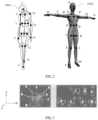
- FIG. 2 shows an 18-node human body framework model, which is used as an example. If in any two human body framework models, ratios of distances between neighboring and interconnected nodes in all same human body parts including a forearm, an upper arm, a torso, a head, a waist, buttocks, a thigh, and a crus to references (central axis) of the human body frameworks are the same, the two human body frameworks are totally the same. As shown in FIG.
- ⁇ Z Base ⁇ Zi Base i , where Z herein refers to a framework length of the target object, Base refers to a framework reference length of the target object, Zi refers to a framework length of a model whose number is i in a 3D model library, Base i refers to a framework reference length of the model whose number is i in the 3D model library, and ⁇ is a permissible difference, where a value of the permissible difference may be obtained according to an experience value, or selected according to a specific situation.
- the obtaining framework parameters of the target object according to depth values of pixels in the 3D depth image of the target object may be specifically implemented by using the following steps: First, a central axis of the target object is obtained according to depth value of the all pixels in the 3D depth image of the target object and by using a linear least square method.
- the central axis is generally a spine of the human body.
- transverse thicknesses of the graphic contour of the target object are calculated along multiple first lines perpendicular to the central axis.
- a transverse framework of the human body is obtained by extending along multiple first lines perpendicular to the spine.
- Longitudinal thicknesses of the graphic contour of the target object are calculated along multiple second lines parallel to the central axis.
- the central axis is the spine of the human body
- a longitudinal framework of the human body is obtained by extending along multiple second lines parallel to the spine.
- a framework of the target object is constituted by using areas limited by the first lines and the second lines, where the corresponding transverse thicknesses and longitudinal thicknesses are the framework parameters of the target object.
- the 3D model matching both the framework parameters and the graphic contour that are of the target object is retrieved from the 3D model library.
- the 3D model library herein may be a standard model library stored in a cloud server, or a standard model library locally stored, and a model with a highest matching degree with the foregoing obtained framework parameters and graphic contour that are of the target object is retrieved from such a standard model library.
- Prestored model library data may be from human body 3D data provided by a third-party data provider, and the data generally includes various typical body shape 3D data of all countries, areas, and races all over the world.
- the prestored model library data may be from an auto-learning result of a machine, for example, an owner of an intelligent terminal may obtain auto-learning 3D model data by measuring, calculating, and adjusting a specific target within a period of time. It may be understood that, in addition to human body 3D data, there may be 3D data of an animal body or another visible target object, and details are not described herein.
- a prestored 3D model includes at least two types of parameters: a graphic contour and a framework parameter.
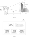
- 2D contour parameters of a 3D model of a bull in this example separately indicate graphic contours of the target that are recorded by projecting from directions of the target, including projection contours from 1 side, 2 front, 4 left-front, 5 left-rear, 6 right-front, and 7 right-rear.
- a projection contour from 3 directly above is generally not mandatory.
- the graphic contours may include projection graphic contours (not shown in the figure) of the target that are recorded from all angles of left-directly front, left-directly rear, right-directly front, right-directly rear, and the like.
- a chen's algorithm that is, a 2D Zernike moment descriptor and a Fourier descriptor (FD, Fourier Descriptor)
- FD Fourier Descriptor
- a similarity between a graphic contour of a target object and a graphic contour of a 3D model of a bull in a 3D model library is the highest, and a returned observation result is that the graphic contour of the target object is a projection of the 3D model of the bull along a negative direction of an X-coordinate.
- the retrieving a 3D model matching the framework parameters and the graphic contour that are of the target object from a 3D model library, and obtaining a parameter ratio of the 3D model specifically includes:
- the 3D model library includes graphic contours of all visual angles of the 3D model, and includes at least the front-view graphic contour of the 3D model.
- the performing matching between the graphic contour of the target object and a graphic contour of a 3D model in the 3D model library, to obtain a graphic contour of a 3D model with a highest matching degree includes:
- framework data in a standard 3D model library needs to be rotated and projected to a negative direction of an X-axis, to implement accurate framework similarity retrieving and matching.
- the 3D model that is of the target object and that is obtained by means of retrieving in S103 is a standard unit model, and the parameter ratio of the 3D model further needs to be multiplied by at least one real geometric parameter (for example, an actual height or arm length of a user) of the target object, and a 3D model completely matching the target object can be obtained only after same-ratio amplifying is performed.
- the at least one real size of the target object is obtained by using the following steps:
- a user and a photographer do not know a real geometric parameter of the target object, and therefore, at least one real geometric parameter, also referred to as a real size herein, of the target object needs to be obtained in a real-time measurement manner.
- An optional manner is: measuring and calculating a height of the target by using a method of recording an image of the target object by using a camera.
- a speaker component of a mobile terminal periodically transmits a sound wave signal to the target, and this transmitting action may be synchronous with a detecting action of a 3D sensor.
- the sound wave signal may be beyond a frequency range (20 Hz to 20 KHz) of human body auditory sensation, to avoid causing interference to the user and the human body target.
- the sound wave signal is received by a microphone component.
- the image of the target object is recorded in a camera component.
- a height h of an image of the target object may be obtained by means of calculation by using an image contour identification technology.
- this solution may also be used to measure another geometric parameter such as a length or a width of the target, and details are not described herein.
- the at least one real size of the target object may be measured by using another method in addition to the foregoing measurement method, for example:
- the mobile terminal records at least two photos of the target object at the same time, and these photos are captured by using camera components with different focal distance parameters.
- both D21 and D22 are known parameters, and h1 and h2 may be obtained by means of calculation by using a pixel method.
- the parameter ratio of the 3D model, obtained by means of retrieving, with the highest matching degree may be multiplied by the real height H of the target, so that a real framework model of the target may be obtained.
- the sign data of the human body target object may be further obtained by means of calculation by using a real geometric parameter that is of the target and that is directly entered from a touchscreen of an I/O interface of the mobile phone, where the real geometric parameter may be one piece of data such as a height, an arm length, or a shoulder width.
- the user may obtain relatively accurate sign data of the target object by means of calculation by dynamically adjusting an entered real geometric parameter of the target.
- various sign parameters such as a weight, chest, waist, and hip sizes, an arm length, and a shoulder width of a human body target 420 may be obtained by means of calculation according to a specific parameter (such as a density) in a sign feature parameter library, and are displayed on a user input/output interface.
- a specific parameter such as a density
- the various sign parameters may be used for clothes size and matching suggestion, advertisement push, and the like.
- this embodiment may be not only applied to sign data measurement in a process of shooting a target object, but may also be applied to a 3D measurement and sign data obtaining process in video shooting of a mobile target object.
- a 3D depth image of a target object is obtained, and framework parameters and a graphic contour that are of the target object are restored according to the 3D depth image, and therefore, a 3D model corresponding to the target object is retrieved based on the graphic contour and the framework parameters, and further, sign data of the target object is obtained by using the 3D model, so that users can obtain a sign parameter of a seen object anywhere at any time by performing virtual reconstruction by using a terminal, and user experience of "what you see is what you get" is implemented.
- background noise reduction is performed on the 3D depth image based on background noise reduction processing, to obtain a first 3D target depth image, to obtain an independent graphic contour of the target object, which specifically includes: performing difference calculation on depth values of pixels in the first 3D target depth image, to obtain the graphic contour of the target object.
- the performing background noise reduction processing on the 3D depth image, to obtain the first 3D target depth image includes:
- the foregoing obtained first 3D target depth image may be further processed, that is:
- the performing edge noise reduction processing on the first 3D target depth image, to obtain a second 3D target depth image includes:
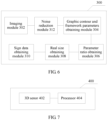
- FIG. 5 shows an apparatus 300 for obtaining sign data of a target object according to an embodiment of the present invention, and the apparatus includes:
- an imaging device obtains a 3D depth image of a target object; a graphic contour and framework parameters obtaining module restores, according to the 3D depth image, framework parameters and a graphic contour that are of the target object; a parameter ratio obtaining module retrieves, based on the graphic contour and the framework parameters, a 3D model corresponding to the target object; a sign data obtaining module obtains sign data of the target object according to the 3D model. Therefore, users can obtain a sign parameter of a seen object anywhere at any time by performing virtual reconstruction by using a terminal, and user experience of "what you see is what you get" is implemented.
- the imaging module 302 may specifically include:
- the graphic contour and framework parameters obtaining module is specifically configured to perform difference calculation on the depth values of the pixels in the 3D depth image, to obtain the graphic contour of the target object; and specifically, the performing difference calculation on the depth values of the pixels in the 3D depth image includes:
- the foregoing apparatus 300 further includes a noise reduction module 312, where
- noise reduction module 3 12 is specifically configured to:
- noise reduction module 3 12 may be further configured to:
- the noise reduction module 312 is specifically configured to:
- the graphic contour and framework parameters obtaining module 304 is specifically configured to:
- the parameter ratio obtaining module 306 is specifically configured to:
- the 3D model library includes graphic contours of all visual angles of the 3D model, and includes at least the front-view graphic contour of the 3D model.
- the parameter ratio obtaining module 306 is specifically configured to:
- the real size obtaining module 308 is specifically configured to:
- FIG. 7 shows a terminal 400 for obtaining sign data of a target object according to an embodiment of the present invention, and the terminal includes:
- the 3D sensor 402 may be specifically configured to: transmit a reference pattern to the target object, receive a secondary pattern obtained after the reference pattern is reflected by the target object, calculate an offset value of the secondary pattern relative to the reference pattern, obtain the distance information by performing Fourier transformation on the offset value, and obtain the 3D depth image by using the distance information.
- the processor 404 is specifically configured to perform difference calculation on the depth values of the pixels in the 3D depth image, to obtain the graphic contour of the target object; and specifically, the performing difference calculation on the depth values of the pixels in the 3D depth image includes:
- the processor 404 may be further specifically configured to perform background noise reduction processing on the 3D depth image, to obtain a first 3D target depth image; and correspondingly, the performing difference calculation on the depth values of the pixels in the 3D depth image, to obtain the graphic contour of the target object includes: performing difference calculation on depth values of pixels in the first 3D target depth image, to obtain the graphic contour of the target object.
- processor 404 may be specifically configured to:
- processor 404 may be further specifically configured to:
- processor 404 may be specifically configured to:
- processor 404 may be specifically configured to:
- processor 404 may be specifically configured to:
- the 3D model library includes graphic contours of all visual angles of the 3D model, and includes at least the front-view graphic contour of the 3D model.
- the processor 404 may be specifically configured to: describe the graphic contour of the target object by using a Zernike moment descriptor and a Fourier descriptor, to obtain first description information;
- the processor 404 is specifically configured to:
- the program may be stored in a computer readable storage medium.
- the storage medium may include a flash memory, a read-only memory (Read-Only Memory, ROM), a random access memory (Random Access Memory, RAM), a magnetic disk, and an optical disc.
Description
- The present invention relates to the data obtaining field, and in particular, to a method and a terminal for obtaining sign data of a target object.
- To implement "what you see is what you get" on an intelligent terminal is always a dream of most users. For example, in 2009, Google launches a navigation and geolocation service "Google Maps Navigation" that is based on street views. However, this service needs to be supported by background-powerful geographic image data, a search and calculation capability, and a ubiquitous high-speed network link, and in many areas with narrow network coverage, such a service can hardly be implemented. The document
WO 2014/022608 A2 discloses s method to help a user visualize how a wearable article will look on the user's body. The method includes receiving an image of the user's body from an image-capture component. Based on the image, a posable, three-dimensional, virtual avatar is constructed to substantially resemble the user. Data is obtained that identifies the wearable article as being selected for the user. This data includes a plurality of metrics that at least partly define the wearable article. Then, a virtualized form of the wearable article is attached to the avatar, which is provided to a display component for the user to review. - The document MIAOLONG YUAN ET AL: "A Mixed Reality Virtual Clothes Try-On System", IEEE TRANSACTIONS ON MULTIMEDIA, vol. 15, no. 8, December 2013 (2013-12), pages 1958-1968, ISSN: 1520-9210, DOI: 10.1109/TMM.2013.2280560 discloses a mixed reality system for 3D virtual clothes try-on that enables a user to see herself wearing virtual clothes while looking at a mirror display, without taking off her actual clothes. The user can select various virtual clothes for trying-on. The system physically simulates the selected virtual clothes on the user's body in real-time and the user can see virtual clothes fitting on the her mirror image from various angles as she moves. An invisible (or partially visible) avatar is automatically customized based on the user's body size and the skin colour and used for proper clothes fitting, alignment and clothes simulation in the virtual try-on system.
- Embodiments of the present invention are defined by the claims. A method and a terminal for obtaining sign data of a target object are provided. A pattern and a framework that are of a target object are restored from a photographed image of the target object, and sign data of the target object is presented to a user with reference to various local or cloud search applications, to implement experience of "what you see is what you get" for users.
- According to a first aspect, the present invention provides a method for obtaining sign data of a target object as defined in
claim 1. According to a second aspect, the present invention provides a terminal for obtaining sign data of a target object as defined inclaim 2. In the present invention, with reference to real-time obtaining of a terminal and a local 3D model library or a 3D model library in the cloud, the sign data of the target object can be presented to people in a real-time manner, and a dream of "what you see is what you get" of people can be implemented. - To describe the technical solutions in the embodiments of the present invention more clearly, the following briefly describes the accompanying drawings required for describing the embodiments.
-
FIG. 1 is a schematic flowchart of a method for obtaining sign data of a target object according to an embodiment of the present invention; -
FIG. 2 is a reference diagram of specific steps of a method for obtaining sign data of a target object according to an embodiment of the present invention; -
FIG. 3 is another reference diagram of specific steps of a method for obtaining sign data of a target object according to an embodiment of the present invention; -
FIG. 4 is still another reference diagram of specific steps of a method for obtaining sign data of a target object according to an embodiment of the present invention; -
FIG. 5 is a first schematic diagram of an apparatus for obtaining sign data of a target object according to an embodiment of the present invention; -
FIG. 6 is a second schematic diagram of an apparatus for obtaining sign data of a target object according to an embodiment of the present invention; and -
FIG. 7 is a schematic diagram of a terminal for obtaining sign data of a target object according to an embodiment of the present invention. - The following clearly describes the technical solutions in the embodiments of the present invention with reference to the accompanying drawings in the embodiments of the present invention. Apparently, the described embodiments are merely some but not all of the embodiments of the present invention. The embodiments of the present invention provide a method for obtaining sign data of a target object. A pattern and a framework that are of a target object are restored from a photographed image of the target object, and sign data of the target object is presented to a user with reference to various local or cloud search applications, to implement a dream of "what you see is what you get" of people.
- Referring to
FIG. 1, FIG. 1 shows a method 100 for obtaining sign data of a target object according to an embodiment of the present invention, and the method includes:
S101. Obtain a 3D depth image of a target object, where the 3D depth image is a two-dimensional image with distance information, and the distance information includes a distance between the target object and an imaging device. - In specific implementation, the target object may be photographed by using a camera of a terminal, to obtain the 3D depth image. Optionally, this obtaining process may be implemented in the following manner:
First, the terminal transmits a reference pattern to the foregoing target object. There may be multiple choices for the reference pattern herein, for example, a square raster pattern, a cellular raster pattern, or the reference pattern may be a pattern including distributed speckles, which is not limited herein. In addition, for protection of the target object, a light generation source of the reference pattern is an infrared beam generator that can perform beam power control, and therefore, when the target object is a human body or an animal body, the light generation source of the reference pattern causes no harm to the human body or the animal body. - As described above, the terminal transmits the reference pattern to the target object, and a feature size parameter of the reference pattern is preset. For example, when the reference pattern is a raster pattern, both a shape and a spacing of a raster may be preset.
- Then, a secondary pattern obtained after the reference pattern is reflected by the target object is received. The receiving herein may be that the terminal shoots the target object by using a build-in or outer-connected camera, to obtain the secondary pattern obtained after the foregoing reference pattern is reflected by the target object. A two-dimensional image of the target object is obtained together. Because obtaining, by a camera, a two-dimensional planar image of an object is a mature technology, a method for implementing the technology is not described or limited herein.
- Further, an offset value of the secondary pattern relative to the reference pattern is calculated. Because the feature size parameter of the reference pattern is preset, the offset value of the secondary pattern relative to the reference pattern is calculated after the secondary pattern is obtained. The offset value may also be referred to as a deformation value, that is, a deformation amount, of the secondary pattern, generated relative to the reference pattern is reflected by using the value.
- Finally, the distance information is obtained by performing Fourier transformation on the offset value, and the 3D depth image is obtained by using the distance information.
- Based on the foregoing obtained offset value, the offset value is processed by using Fourier transformation, to obtain the distance information. The distance information herein is used to describe a distance between the imaging camera and the shot target object, and may be specifically embodied as a distance between each pixel in the two-dimensional image of the target object and the imaging camera. Based on this distance information and with reference to the foregoing shot and obtained two-dimensional image of the target object, the 3D depth image with the distance information may be obtained.
- S102. Obtain, according to depth values of pixels in the 3D depth image of the target object, framework parameters and a graphic contour that are of the target object. The depth value is a distance that is between a point on the target object and the imaging device and that is obtained according to the distance information.
- The 3D depth image of the target object includes all pixels forming the image. The distance information obtained according to S101 may be used to describe distance information, that is, the depth value herein of distances between these pixels and the imaging camera. Further, the framework parameters and the graphic contour that are of the target object are obtained according to the depth value. In a specific implementation process, obtaining the graphic contour of the target object according to the depth value may be implemented according to the following method.
- Difference calculation is performed on the depth values of the pixels in the 3D depth image, to obtain the graphic contour of the target object. Specifically, the difference calculation herein may include the following steps:
First, a depth value difference between a pixel depth value of a first pixel in the 3D depth image and a pixel depth value of each of four neighboring pixels connected to the first pixel is calculated, to obtain four first depth difference values, where the first pixel herein may be a pixel randomly selected from the 3D depth image. Location relationships between the four neighboring pixels connected to the first pixel and the first pixel may be separately left, right, above, and below. - Then, when at least one first depth difference value in the four first depth difference values is greater than a first difference threshold, a neighboring pixel corresponding to the at least one first depth difference value is marked as a contour location, where the first difference threshold herein may be preset according to experience.
- Then, it is queried whether a pixel marked as a contour location exists in eight neighboring pixels connected to a second pixel in the 3D depth image; if the pixel marked as a contour location exists in the eight neighboring pixels connected to the second pixel in the 3D depth image, difference calculation is separately performed between a pixel depth value of the second pixel and a pixel depth value of a pixel that is in the eight neighboring pixels connected to the second pixel and that is a non-contour location, to obtain a second depth difference value. When at least one of the second depth difference value is greater than a second difference threshold, the second pixel is marked as a contour location, where the second pixel herein may also be any pixel in the 3D depth image, where the second difference threshold herein may be preset according to experience. When the pixel marked as a contour location exists in the eight neighboring pixels connected to the second pixel, difference calculation is separately performed between the pixel depth value of the second pixel and a pixel depth value of a pixel except the pixel shown to be marked as a contour location. Once a difference calculation result obtained by means of calculation is greater than the second difference threshold, the second pixel is marked as a contour location.
- Finally, the graphic contour of the target object is obtained according to pixels marked as contour locations. Based on the foregoing steps, the pixels in the foregoing 3D depth image are grouped into pixels that are marked as contour locations and pixels that are not marked as contour locations, and all pixels that are marked as contour locations form the graphic contour of the target object. In addition, the framework parameters of the target object are obtained according to the depth values of the pixels in the 3D depth image of the target object. First, a principle of the framework parameter should be understood. A human body framework parameter is used as an example, and a framework structure in human anatomy meets a specific natural ratio feature. Regardless of a westerner or an easterner, a male or a female, and a minor or a major, skeleton lengths thereof are different, but basic skeleton structures are the same.
FIG. 2 shows an 18-node human body framework model, which is used as an example. If in any two human body framework models, ratios of distances between neighboring and interconnected nodes in all same human body parts including a forearm, an upper arm, a torso, a head, a waist, buttocks, a thigh, and a crus to references (central axis) of the human body frameworks are the same, the two human body frameworks are totally the same. As shown inFIG. 2 , it is assumed that a ratio of a distance between any neighboring and interconnected nodes in each part of a reconstructed humanbody framework model 1601 to a reference (central axis) of the framework and a ratio of a same framework of a same part of a standard humanbody framework model 1602 to a reference (central axis) of the framework are the same or highly similar, it may be considered that theframework 1601 and theframework 1602 are a same 3D model, that is:
Z herein refers to a framework length of the target object, Base refers to a framework reference length of the target object, Zi refers to a framework length of a model whose number is i in a 3D model library, Base i refers to a framework reference length of the model whose number is i in the 3D model library, and Δ is a permissible difference, where a value of the permissible difference may be obtained according to an experience value, or selected according to a specific situation. - In a specific implementation process, the obtaining framework parameters of the target object according to depth values of pixels in the 3D depth image of the target object may be specifically implemented by using the following steps:
First, a central axis of the target object is obtained according to depth value of the all pixels in the 3D depth image of the target object and by using a linear least square method. When the foregoing target object is a human body, the central axis is generally a spine of the human body. Then, transverse thicknesses of the graphic contour of the target object are calculated along multiple first lines perpendicular to the central axis. As described above, when the central axis is the spine of the human body, a transverse framework of the human body is obtained by extending along multiple first lines perpendicular to the spine. - Longitudinal thicknesses of the graphic contour of the target object are calculated along multiple second lines parallel to the central axis. As described above, when the central axis is the spine of the human body, a longitudinal framework of the human body is obtained by extending along multiple second lines parallel to the spine.
- A framework of the target object is constituted by using areas limited by the first lines and the second lines, where the corresponding transverse thicknesses and longitudinal thicknesses are the framework parameters of the target object.
- S103. Retrieve a 3D model matching the framework parameters and the graphic contour that are of the target object from a 3D model library, and obtain a parameter ratio of the 3D model.
- Based on the foregoing obtained framework parameters and graphic contour that are of the target object, the 3D model matching both the framework parameters and the graphic contour that are of the target object is retrieved from the 3D model library. The 3D model library herein may be a standard model library stored in a cloud server, or a standard model library locally stored, and a model with a highest matching degree with the foregoing obtained framework parameters and graphic contour that are of the target object is retrieved from such a standard model library. Prestored model library data may be from
human body 3D data provided by a third-party data provider, and the data generally includes varioustypical body shape 3D data of all countries, areas, and races all over the world. Optionally, the prestored model library data may be from an auto-learning result of a machine, for example, an owner of an intelligent terminal may obtain auto-learning 3D model data by measuring, calculating, and adjusting a specific target within a period of time. It may be understood that, in addition tohuman body 3D data, there may be 3D data of an animal body or another visible target object, and details are not described herein. - In the technical field of the present invention, multiple related
algorithms support 3D model retrieving and matching. However, to simplify calculation in a terminal and in the cloud and improve a response speed, in this embodiment of the present invention, a prestored 3D model includes at least two types of parameters: a graphic contour and a framework parameter. As shown inFIG. 3, 2D contour parameters of a 3D model of a bull in this example separately indicate graphic contours of the target that are recorded by projecting from directions of the target, including projection contours from 1 side, 2 front, 4 left-front, 5 left-rear, 6 right-front, and 7 right-rear. A projection contour from 3 directly above is generally not mandatory. Alternatively, to increase matching accuracy, the graphic contours may include projection graphic contours (not shown in the figure) of the target that are recorded from all angles of left-directly front, left-directly rear, right-directly front, right-directly rear, and the like. During matching calculation, a chen's algorithm, that is, a 2D Zernike moment descriptor and a Fourier descriptor (FD, Fourier Descriptor), is used to obtain, by means of comparison, a similarity between one or more target object graphic contours of a same target object and a graphic contour in each direction of the 3D model library, a graphic contour having a highest similarity is retrieved, and a visual angle value of a projection of a 3D standard model corresponding to the graphic contour is returned. As shown inFIG. 3 , a similarity between a graphic contour of a target object and a graphic contour of a 3D model of a bull in a 3D model library is the highest, and a returned observation result is that the graphic contour of the target object is a projection of the 3D model of the bull along a negative direction of an X-coordinate. - Specifically, the retrieving a 3D model matching the framework parameters and the graphic contour that are of the target object from a 3D model library, and obtaining a parameter ratio of the 3D model specifically includes:
- performing matching between the graphic contour of the target object and a graphic contour of a 3D model in the 3D model library, to obtain a graphic contour of a 3D model with a highest matching degree;
- when the graphic contour of the 3D model is not a front-view graphic contour of the 3D model, obtaining the front-view graphic contour of the 3D model according to the graphic contour of the 3D model;
- calculating a visual angle parameter of the 3D model according to the graphic contour of the 3D model and the front-view graphic contour of the 3D model, where the visual angle parameter is a visual angle that is of the graphic contour of the 3D model based on the front-view graphic contour of the 3D model;
- rotating the front-view graphic contour of the 3D model based on the visual angle parameter, to obtain framework parameters of the 3D model;
- obtaining, by means of comparison, a similarity between the framework parameters of the target object and the framework parameters of the 3D model, where when the similarity is less than a preset value, the 3D model is the 3D model matching the framework parameters and the graphic contour that are of the target object; and
- obtaining the parameter ratio of the 3D model by using the 3D model.
- As described above, the 3D model library includes graphic contours of all visual angles of the 3D model, and includes at least the front-view graphic contour of the 3D model.
- Further, the performing matching between the graphic contour of the target object and a graphic contour of a 3D model in the 3D model library, to obtain a graphic contour of a 3D model with a highest matching degree includes:
- describing the graphic contour of the target object by using a Zernike moment descriptor and a Fourier descriptor, to obtain first description information;
- describing the graphic contour of the 3D model in the 3D model library by using the Zernike moment descriptor and the Fourier descriptor, to obtain second description information; and
- comparing the first description information and the second description information, and using a graphic contour of a 3D model corresponding to second description information that differs from the first description information by a preset threshold as the graphic contour of the 3D model with the highest matching degree.
- As shown in
FIG. 3 , framework data in a standard 3D model library needs to be rotated and projected to a negative direction of an X-axis, to implement accurate framework similarity retrieving and matching. - An ideal effect can be achieved by using this retrieving method even when an environment changes. Generally, different clothes worn by and postures of a human body target affect a human body graphic contour obtained by means of calculation by using a 3D depth image. For example, because light clothes are worn in summer and heavy clothes are worn in winter, there is a large difference between human body graphic contours obtained by means of calculation. If similarity retrieving is performed only according to a human body graphic contour, an obtained 3D model has a large deviation, and therefore, a framework parameter is introduced herein. In a case in which both the framework parameters and the graphic contour that are of the target object are determined, accuracy of an obtained 3D model is high.
- S 104. Obtain at least one real size of the target object.
- The 3D model that is of the target object and that is obtained by means of retrieving in S103 is a standard unit model, and the parameter ratio of the 3D model further needs to be multiplied by at least one real geometric parameter (for example, an actual height or arm length of a user) of the target object, and a 3D model completely matching the target object can be obtained only after same-ratio amplifying is performed. The at least one real size of the target object is obtained by using the following steps:
- transmitting a sound wave signal to the target object;
- receiving a sound wave signal reflected by the target object;
- obtaining a transmission time of the sound wave signal, where the transmission time is a difference between time of transmitting the sound wave signal and time of receiving the sound wave signal;
- calculating a distance between a surface of the target object and the imaging device by using the transmission time and a propagation velocity of the sound wave signal; and
- calculating the at least one real size of the target object by using the distance and an image distance of the imaging device.
- Specifically, in most using situations, a user and a photographer do not know a real geometric parameter of the target object, and therefore, at least one real geometric parameter, also referred to as a real size herein, of the target object needs to be obtained in a real-time measurement manner. An optional manner is: measuring and calculating a height of the target by using a method of recording an image of the target object by using a camera. When a mobile terminal enables a photographing and 3D depth measurement application, a speaker component of a mobile terminal periodically transmits a sound wave signal to the target, and this transmitting action may be synchronous with a detecting action of a 3D sensor. The sound wave signal may be beyond a frequency range (20 Hz to 20 KHz) of human body auditory sensation, to avoid causing interference to the user and the human body target. When the sound wave signal is returned after meeting the target object, the sound wave signal is received by a microphone component. A distance D1=1/2×V×Δt between the target and the photographer may be obtained by calculating a propagation time Δt of the sound wave signal, where V is a propagation velocity of this frequency sound wave in ambient air. In addition, the image of the target object is recorded in a camera component. A height h of an image of the target object may be obtained by means of calculation by using an image contour identification technology. For a determined mobile terminal, an image distance D2 of a camera component is the only determined hardware parameter. In this way, a real height H of the target object may be obtained by means of calculation according to the following formula:

- Based on a same principle, this solution may also be used to measure another geometric parameter such as a length or a width of the target, and details are not described herein.
- The at least one real size of the target object may be measured by using another method in addition to the foregoing measurement method, for example:
When the user operates the mobile terminal to perform shooting and 3D measurement on the target object, the mobile terminal records at least two photos of the target object at the same time, and these photos are captured by using camera components with different focal distance parameters. In an embodiment shown inFIG. 4 , a terminal camera obtains three photos with different image distances by using three different focal distances. Two photos thereof are used as an example; image distances separately corresponding to the two photos are D21 and D22, imaging heights are h1 and h2, and a lens distance change of two shooting parameters is Δ. Because a real height of a target object is uniquely determined, the photos obviously meet the following geometric formulas:


- In a case in which a hardware parameter of a camera module is determined, both D21 and D22 are known parameters, and h1 and h2 may be obtained by means of calculation by using a pixel method. A height H of the target object may be obtained by means of calculation according to the following formula:

- S105. Obtain sign data of the target object according to the parameter ratio of the 3D model and the at least one real size.
- In a specific operation, the parameter ratio of the 3D model, obtained by means of retrieving, with the highest matching degree may be multiplied by the real height H of the target, so that a real framework model of the target may be obtained.
- In another feasible solution of this embodiment, the sign data of the human body target object may be further obtained by means of calculation by using a real geometric parameter that is of the target and that is directly entered from a touchscreen of an I/O interface of the mobile phone, where the real geometric parameter may be one piece of data such as a height, an arm length, or a shoulder width. Alternatively, the user may obtain relatively accurate sign data of the target object by means of calculation by dynamically adjusting an entered real geometric parameter of the target. Further, optionally, in this embodiment, various sign parameters such as a weight, chest, waist, and hip sizes, an arm length, and a shoulder width of a human body target 420 may be obtained by means of calculation according to a specific parameter (such as a density) in a sign feature parameter library, and are displayed on a user input/output interface. Alternatively, with reference to various business databases and customary setting of the user, the various sign parameters may be used for clothes size and matching suggestion, advertisement push, and the like.
- It should be noted that this embodiment may be not only applied to sign data measurement in a process of shooting a target object, but may also be applied to a 3D measurement and sign data obtaining process in video shooting of a mobile target object.
- In this embodiment of the present invention, a 3D depth image of a target object is obtained, and framework parameters and a graphic contour that are of the target object are restored according to the 3D depth image, and therefore, a 3D model corresponding to the target object is retrieved based on the graphic contour and the framework parameters, and further, sign data of the target object is obtained by using the 3D model, so that users can obtain a sign parameter of a seen object anywhere at any time by performing virtual reconstruction by using a terminal, and user experience of "what you see is what you get" is implemented.
- It should be noted that, in most photographing applications, if a main target is a human body, a result obtained by means of calculation is accurate. However, if two or more persons appear and overlap with or shield each other in a real scenario, different human body objects need to be separately processed during processing. A simple method is processing overlapped human body targets in a background noise manner and by using an image depth filtering algorithm, and another feasible method is separating overlapped images and performing calculation. It should be noted that, in the technical solution involved in this embodiment, a single target object or an independent target object obtained after separation is mainly involved.
- In a new embodiment, for enabling the obtained graphic contour of the target object to be more accurate, in this embodiment, background noise reduction is performed on the 3D depth image based on background noise reduction processing, to obtain a first 3D target depth image, to obtain an independent graphic contour of the target object, which specifically includes: performing difference calculation on depth values of pixels in the first 3D target depth image, to obtain the graphic contour of the target object.
- Specifically, the performing background noise reduction processing on the 3D depth image, to obtain the first 3D target depth image includes:
- setting a depth threshold; and
- comparing a depth value of each pixel in the 3D depth image with the depth threshold, filtering out a pixel that is in the 3D depth image and whose pixel depth value is greater than the depth threshold, and obtaining remaining pixels to form the first 3D target depth image.
- Further, in a new embodiment, the foregoing obtained first 3D target depth image may be further processed, that is:
- performing edge noise reduction processing on the first 3D target depth image, to obtain a second 3D target depth image; and
- correspondingly, the performing difference calculation on the depth values of the pixels in the 3D depth image, to obtain the graphic contour of the target object includes: performing difference calculation on depth values of pixels in the second 3D target depth image, to obtain the graphic contour of the target object.
- Therefore, an independent graphic contour with a clear edge may be obtained.
- Specifically, the performing edge noise reduction processing on the first 3D target depth image, to obtain a second 3D target depth image includes:
- segmenting the first 3D target depth image into multiple pixel blocks;
- setting a pixel depth segment interval;
- performing average processing on depth value of all pixels in each of the pixel blocks, to obtain a pixel average value of each of the pixel blocks; and
- mapping the pixel average value to a corresponding interval in the pixel depth segment interval, and combining pixel blocks corresponding to all pixel average values in a same interval, to obtain the second 3D target depth image.
- Referring to
FIG. 5, FIG. 5 shows anapparatus 300 for obtaining sign data of a target object according to an embodiment of the present invention, and the apparatus includes: - an
imaging module 302, configured to obtain a 3D depth image of a target object, where the 3D depth image is a two-dimensional image with distance information, and the distance information includes a distance between the target object and an imaging device; - a graphic contour and framework
parameters obtaining module 304, configured to obtain, according to depth values of pixels in the 3D depth image of the target object, framework parameters and a graphic contour that are of the target object, where the depth value is a distance that is between a point on the target object and the imaging device and that is obtained according to the distance information; - a parameter ratio obtaining module 306, configured to retrieve a 3D model matching the framework parameters and the graphic contour that are of the target object from a 3D model library, and obtain a parameter ratio of the 3D model;
- a real
size obtaining module 308, configured to obtain at least one real size of the target object; and - a sign
data obtaining module 310, configured to obtain sign data of the target object according to the parameter ratio of the 3D model and the at least one real size. - In this embodiment of the present invention, an imaging device obtains a 3D depth image of a target object; a graphic contour and framework parameters obtaining module restores, according to the 3D depth image, framework parameters and a graphic contour that are of the target object; a parameter ratio obtaining module retrieves, based on the graphic contour and the framework parameters, a 3D model corresponding to the target object; a sign data obtaining module obtains sign data of the target object according to the 3D model. Therefore, users can obtain a sign parameter of a seen object anywhere at any time by performing virtual reconstruction by using a terminal, and user experience of "what you see is what you get" is implemented.
- On the basis of
Embodiment 2, further, in another embodiment, theimaging module 302 may specifically include: - a transmit unit, configured to transmit a reference pattern to the target object;
- a receive unit, configured to receive a secondary pattern obtained after the reference pattern is reflected by the target object;
- a calculation unit, configured to calculate an offset value of the secondary pattern relative to the reference pattern; and
- an image obtaining unit, configured to: obtain the distance information by performing Fourier transformation on the offset value, and obtain the 3D depth image by using the distance information.
- On the basis of the foregoing embodiment, further, in another embodiment, the graphic contour and framework parameters obtaining module is specifically configured to perform difference calculation on the depth values of the pixels in the 3D depth image, to obtain the graphic contour of the target object; and
specifically, the performing difference calculation on the depth values of the pixels in the 3D depth image includes: - calculating a depth value difference between a pixel depth value of a first pixel in the 3D depth image and a pixel depth value of each of four neighboring pixels connected to the first pixel, to obtain four first depth difference values;
- when at least one first depth difference value in the four first depth difference values is greater than a first difference threshold, marking a neighboring pixel corresponding to the at least one first depth difference value as a contour location;
- querying whether a pixel marked as a contour location exists in eight neighboring pixels connected to a second pixel in the 3D depth image;
- if the pixel marked as a contour location exists in the eight neighboring pixels connected to the second pixel in the 3D depth image, separately performing difference calculation between a pixel depth value of the second pixel and a pixel depth value of a pixel that is in the eight neighboring pixels connected to the second pixel and that is a non-contour location, to obtain a second depth difference value;
- when at least one of the second depth difference value is greater than a second difference threshold, marking the second pixel as a contour location; and
- obtaining the graphic contour of the target object according to pixels marked as contour locations.
- On the basis of the foregoing embodiment, further, referring to
FIG. 6 , in another embodiment, the foregoingapparatus 300 further includes anoise reduction module 312, where - the
noise reduction module 312 is configured to: - perform background noise reduction processing on the 3D depth image, to obtain a first 3D target depth image; and
- correspondingly, the performing difference calculation on the depth values of the pixels in the 3D depth image, to obtain the graphic contour of the target object includes: performing difference calculation on depth values of pixels in the first 3D target depth image, to obtain the graphic contour of the target object.
- Further, the
noise reduction module 3 12 is specifically configured to: - set a depth threshold; and
- compare a depth value of each pixel in the 3D depth image with the depth threshold, filter out a pixel that is in the 3D depth image and whose pixel depth value is greater than the depth threshold, and obtain remaining pixels to form the first 3D target depth image.
- Further, the
noise reduction module 3 12 may be further configured to: - perform edge noise reduction processing on the first 3D target depth image, to obtain a second 3D target depth image; and
- correspondingly, the performing difference calculation on the depth values of the pixels in the 3D depth image, to obtain the graphic contour of the target object includes: performing difference calculation on depth values of pixels in the second 3D target depth image, to obtain the graphic contour of the target object.
- Further, optionally, the
noise reduction module 312 is specifically configured to: - segment the first 3D target depth image into multiple pixel blocks;
- set a pixel depth segment interval;
- perform average processing on depth value of all pixels in each of the pixel blocks, to obtain a pixel average value of each of the pixel blocks; and
- map the pixel average value to a corresponding interval in the pixel depth segment interval, and combine pixel blocks corresponding to all pixel average values in a same interval, to obtain the second 3D target depth image.
- On the basis of the foregoing embodiment, further, in another embodiment, the graphic contour and framework
parameters obtaining module 304 is specifically configured to: - obtain a central axis of the target object according to depth value of all pixels in the 3D depth image of the target object and by using a linear least square method;
- calculate transverse thicknesses of the graphic contour of the target object along multiple first lines perpendicular to the central axis;
- calculate longitudinal thicknesses of the graphic contour of the target object along multiple second lines parallel to the central axis; and
- constitute a framework of the target object by using areas limited by the first lines and the second lines, where the corresponding transverse thicknesses and longitudinal thicknesses are the framework parameters of the target object.
- On the basis of the foregoing embodiment, further, in another embodiment, the parameter ratio obtaining module 306 is specifically configured to:
- perform matching between the graphic contour of the target object and a graphic contour of a 3D model in the 3D model library, to obtain a graphic contour of a 3D model with a highest matching degree;
- when the graphic contour of the 3D model is not a front-view graphic contour of the 3D model, obtain the front-view graphic contour of the 3D model according to the graphic contour of the 3D model;
- calculate a visual angle parameter of the 3D model according to the graphic contour of the 3D model and the front-view graphic contour of the 3D model, where the visual angle parameter is a visual angle that is of the graphic contour of the 3D model based on the front-view graphic contour of the 3D model;
- rotate the front-view graphic contour of the 3D model based on the visual angle parameter, to obtain framework parameters of the 3D model;
- obtain, by means of comparison, a similarity between the framework parameters of the target object and the framework parameters of the 3D model, where when the similarity is less than a preset value, the 3D model is the 3D model matching the framework parameters and the graphic contour that are of the target object; and
- obtain the parameter ratio of the 3D model by using the 3D model.
- The 3D model library includes graphic contours of all visual angles of the 3D model, and includes at least the front-view graphic contour of the 3D model.
- On the basis of the foregoing embodiment, further, in another embodiment, the parameter ratio obtaining module 306 is specifically configured to:
- describe the graphic contour of the target object by using a Zernike moment descriptor and a Fourier descriptor, to obtain first description information;
- describe the graphic contour of the 3D model in the 3D model library by using the Zernike moment descriptor and the Fourier descriptor, to obtain second description information; and
- compare the first description information and the second description information, and use a graphic contour of a 3D model corresponding to second description information that differs from the first description information by a preset threshold as the graphic contour of the 3D model with the highest matching degree.
- The real
size obtaining module 308 is specifically configured to: - transmit a sound wave signal to the target object;
- receive a sound wave signal reflected by the target object;
- obtain a transmission time of the sound wave signal, where the transmission time is a difference between time of transmitting the sound wave signal and time of receiving the sound wave signal;
- calculate a distance between a surface of the target object and the imaging device by using the transmission time and a propagation velocity of the sound wave signal; and
- calculate the at least one real size of the target object by using the distance and an image distance of the imaging device.
- Referring to
FIG. 7, FIG. 7 shows a terminal 400 for obtaining sign data of a target object according to an embodiment of the present invention, and the terminal includes: - a
3D sensor 402, configured to obtain a 3D depth image of a target object, where the 3D depth image is a two-dimensional image with distance information, and the distance information includes a distance between the target object and an imaging device; and - a
processor 404, configured to obtain, according to depth values of pixels in the 3D depth image of the target object, framework parameters and a graphic contour that are of the target object, where the depth value is a distance that is between a point on the target object and the imaging device and that is obtained according to the distance information, the processor is further configured to retrieve a 3D model matching the framework parameters and the graphic contour that are of the target object from a 3D model library, and obtain a parameter ratio of the 3D model, and the processor is further configured to obtain at least one real size of the target object and obtain sign data of the target object according to the parameter ratio of the 3D model and the at least one real size. - On the basis of
Embodiment 3, optionally, the3D sensor 402 may be specifically configured to:
transmit a reference pattern to the target object, receive a secondary pattern obtained after the reference pattern is reflected by the target object, calculate an offset value of the secondary pattern relative to the reference pattern, obtain the distance information by performing Fourier transformation on the offset value, and obtain the 3D depth image by using the distance information. - On the basis of the foregoing embodiment, further, optionally, the
processor 404 is specifically configured to perform difference calculation on the depth values of the pixels in the 3D depth image, to obtain the graphic contour of the target object; and
specifically, the performing difference calculation on the depth values of the pixels in the 3D depth image includes: - calculating a depth value difference between a pixel depth value of a first pixel in the 3D depth image and a pixel depth value of each of four neighboring pixels connected to the first pixel, to obtain four first depth difference values;
- when at least one first depth difference value in the four first depth difference values is greater than a first difference threshold, marking a neighboring pixel corresponding to the at least one first depth difference value as a contour location;
- querying whether a pixel marked as a contour location exists in eight neighboring pixels connected to a second pixel in the 3D depth image;
- if the pixel marked as a contour location exists in the eight neighboring pixels connected to the second pixel in the 3D depth image, separately performing difference calculation between a pixel depth value of the second pixel and a pixel depth value of a pixel that is in the eight neighboring pixels connected to the second pixel and that is a non-contour location, to obtain a second depth difference value;
- when at least one of the second depth difference value is greater than a second difference threshold, marking the second pixel as a contour location; and
- obtaining the graphic contour of the target object according to pixels marked as contour locations.
- On the basis of the foregoing embodiment, further, optionally, the
processor 404 may be further specifically configured to perform background noise reduction processing on the 3D depth image, to obtain a first 3D target depth image; and
correspondingly, the performing difference calculation on the depth values of the pixels in the 3D depth image, to obtain the graphic contour of the target object includes: performing difference calculation on depth values of pixels in the first 3D target depth image, to obtain the graphic contour of the target object. - Further, the
processor 404 may be specifically configured to: - set a depth threshold; and
- compare a depth value of each pixel in the 3D depth image with the depth threshold, filter out a pixel that is in the 3D depth image and whose pixel depth value is greater than the depth threshold, and obtain remaining pixels to form the first 3D target depth image.
- On the basis of the foregoing embodiment, further, optionally, the
processor 404 may be further specifically configured to: - perform edge noise reduction processing on the first 3D target depth image, to obtain a second 3D target depth image; and
- correspondingly, the performing difference calculation on the depth values of the pixels in the 3D depth image, to obtain the graphic contour of the target object includes: performing difference calculation on depth values of pixels in the second 3D target depth image, to obtain the graphic contour of the target object.
- Further, the
processor 404 may be specifically configured to: - segment the first 3D target depth image into multiple pixel blocks;
- set a pixel depth segment interval;
- perform average processing on depth value of all pixels in each of the pixel blocks, to obtain a pixel average value of each of the pixel blocks; and
- map the pixel average value to a corresponding interval in the pixel depth segment interval, and combine pixel blocks corresponding to all pixel average values in a same interval, to obtain the second 3D target depth image.
- Further, the
processor 404 may be specifically configured to: - obtain a central axis of the target object according to depth value of all pixels in the 3D depth image of the target object and by using a linear least square method;
- calculate transverse thicknesses of the graphic contour of the target object along multiple first lines perpendicular to the central axis;
- calculate longitudinal thicknesses of the graphic contour of the target object along multiple second lines parallel to the central axis; and
- constitute a framework of the target object by using areas limited by the first lines and the second lines, where the corresponding transverse thicknesses and longitudinal thicknesses are the framework parameters of the target object.
- Further, the
processor 404 may be specifically configured to: - perform matching between the graphic contour of the target object and a graphic contour of a 3D model in the 3D model library, to obtain a graphic contour of a 3D model with a highest matching degree;
- when the graphic contour of the 3D model is not a front-view graphic contour of the 3D model, obtain the front-view graphic contour of the 3D model according to the graphic contour of the 3D model;
- calculate a visual angle parameter of the 3D model according to the graphic contour of the 3D model and the front-view graphic contour of the 3D model, where the visual angle parameter is a visual angle that is of the graphic contour of the 3D model based on the front-view graphic contour of the 3D model;
- rotate the front-view graphic contour of the 3D model based on the visual angle parameter, to obtain framework parameters of the 3D model;
- obtain, by means of comparison, a similarity between the framework parameters of the target object and the framework parameters of the 3D model, where when the similarity is less than a preset value, the 3D model is the 3D model matching the framework parameters and the graphic contour that are of the target object; and
- obtain the parameter ratio of the 3D model by using the 3D model.
- The 3D model library includes graphic contours of all visual angles of the 3D model, and includes at least the front-view graphic contour of the 3D model.
- Further, the
processor 404 may be specifically configured to: describe the graphic contour of the target object by using a Zernike moment descriptor and a Fourier descriptor, to obtain first description information; - describe the graphic contour of the 3D model in the 3D model library by using the Zernike moment descriptor and the Fourier descriptor, to obtain second description information; and
- compare the first description information and the second description information, and use a graphic contour of a 3D model corresponding to second description information that differs from the first description information by a preset threshold as the graphic contour of the 3D model with the highest matching degree.
- The
processor 404 is specifically configured to: - transmit a sound wave signal to the target object;
- receive a sound wave signal reflected by the target object;
- obtain a transmission time of the sound wave signal, where the transmission time is a difference between time of transmitting the sound wave signal and time of receiving the sound wave signal;
- calculate a distance between a surface of the target object and the imaging device by using the transmission time and a propagation velocity of the sound wave signal; and
- calculate the at least one real size of the target object by using the distance and an image distance of the imaging device.
- It should be noted that, the foregoing embodiments all derive from a same inventive concept, and the descriptions of the embodiments have their respective focuses. For a part that is not described in detail in an embodiment, refer to related descriptions in other embodiments.
- Persons of ordinary skill in the art may understand that all or some of the steps of the methods in the embodiments may be implemented by a program instructing relevant hardware. The program may be stored in a computer readable storage medium. The storage medium may include a flash memory, a read-only memory (Read-Only Memory, ROM), a random access memory (Random Access Memory, RAM), a magnetic disk, and an optical disc.
- The embodiments of the present invention are described in detail above. In this specification, the principle and implementation manners of the present invention are described herein through specific examples. The foregoing description about the embodiments is merely intended to help understand the method and core ideas of the present invention, which is defined in the claims.
Claims (2)
- A method for obtaining sign data of a target object, comprising:obtaining (S101) a 3D depth image of a target object, wherein the 3D depth image is a two-dimensional image with distance information, and the distance information comprises a distance between the target object and an imaging device;obtaining (S102), according to depth values of pixels in the 3D depth image of the target object, human body framework parameters and a graphic contour that are of the target object, wherein the depth value is a distance that is between a point on the target object and the imaging device and that is obtained according to the distance information;retrieving (S103) a 3D model (1602) matching the human body framework parameters and the graphic contour that are of the target object from a 3D model library, and obtaining a parameter ratio of the 3D model, wherein the parameter ratio is representative of a ratio of a distance between any neighboring and interconnected nodes in each part of a human body framework;obtaining (S104) at least one real size of the target object; andobtaining (S105) sign data of the target object according to the parameter ratio of the 3D model and the at least one real size, wherein the target object is a human body and the sign data comprises at least one of an arm length or a shoulder width of the human body;characterised in that obtaining the at least one real size of the target object comprises:transmitting a sound wave signal to the target object;receiving a sound wave signal reflected by the target object;obtaining a transmission time of the sound wave signal, wherein the transmission time is a difference between time of transmitting the sound wave signal and time of receiving the sound wave signal;calculating a distance between a surface of the target object and the imaging device by using the transmission time and a propagation velocity of the sound wave signal; andcalculating the at least one real size of the target object by using the distance and a corresponding image distance of the imaging device.
- A terminal (400) for obtaining sign data of a target object, comprising:a 3D sensor (302, 402), configured to obtain a 3D depth image of a target object, wherein the 3D depth image is a two-dimensional image with distance information, and the distance information comprises a distance between the target object and an imaging device; a speaker component; a microphone component; anda processor (404), configured to obtain, according to depth values of pixels in the 3D depth image of the target object, human body framework parameters and a graphic contour that are of the target object, wherein the depth value is a distance that is between a point on the target object and the imaging device and that is obtained according to the distance information, wherein the processor is further configured to retrieve a 3D model (1602) matching the human body framework parameters and the graphic contour that are of the target object from a 3D model library, and obtain a parameter ratio of the 3D model, wherein the parameter ratio is representative of a ratio of a distance between any neighboring and interconnected nodes in each part of a human body framework, and the processor is further configured to obtain at least one real size of the target object and obtain sign data of the target object according to the parameter ratio of the 3D model and the at least one real size, wherein the target object is a human body and the sign data comprises at least one of an arm length or a shoulder width of the human body, wherein the processor is additionally configured to:transmit, by means of the speaker component,a sound wave signal to the target object;receive, by means of the microphone component,a sound wave signal reflected by the target object;obtain a transmission time of the sound wave signal, wherein the transmission time is a difference between time of transmitting the sound wave signal and time of receiving the sound wave signal;calculate a distance between a surface of the target object and the imaging device by using the transmission time and a propagation velocity of the sound wave signal; andcalculate the at least one real size of the target object by using the distance and a corresponding image distance of the imaging device.
Applications Claiming Priority (2)
| Application Number | Priority Date | Filing Date | Title |
|---|---|---|---|
| CN201410301461.2A CN105336005B (en) | 2014-06-27 | 2014-06-27 | A kind of method, apparatus and terminal obtaining target object sign data |
| PCT/CN2015/082539 WO2015197026A1 (en) | 2014-06-27 | 2015-06-26 | Method, apparatus and terminal for acquiring sign data of target object |
Publications (3)
| Publication Number | Publication Date |
|---|---|
| EP3144900A1 EP3144900A1 (en) | 2017-03-22 |
| EP3144900A4 EP3144900A4 (en) | 2017-07-26 |
| EP3144900B1 true EP3144900B1 (en) | 2023-04-05 |
Family
ID=54936983
Family Applications (1)
| Application Number | Title | Priority Date | Filing Date |
|---|---|---|---|
| EP15810950.4A Active EP3144900B1 (en) | 2014-06-27 | 2015-06-26 | Method and terminal for acquiring sign data of target object |
Country Status (7)
| Country | Link |
|---|---|
| US (1) | US9984461B2 (en) |
| EP (1) | EP3144900B1 (en) |
| JP (1) | JP6549620B2 (en) |
| KR (1) | KR101922039B1 (en) |
| CN (1) | CN105336005B (en) |
| BR (1) | BR112016030027B1 (en) |
| WO (1) | WO2015197026A1 (en) |
Families Citing this family (10)
| Publication number | Priority date | Publication date | Assignee | Title |
|---|---|---|---|---|
| IT201600122898A1 (en) * | 2016-12-02 | 2018-06-02 | Ecole Polytechnique Fed Lausanne Epfl | METHODS AND EQUIPMENT TO CODIFY AND DECODE DIGITAL VIDEO IMAGES OR FLOWS |
| JP2018136896A (en) * | 2017-02-24 | 2018-08-30 | キヤノン株式会社 | Information processor, system, information processing method, and manufacturing method of article |
| CN107270829B (en) * | 2017-06-08 | 2020-06-19 | 南京华捷艾米软件科技有限公司 | Human body three-dimensional measurement method based on depth image |
| CN109658515B (en) * | 2017-10-11 | 2022-11-04 | 阿里巴巴集团控股有限公司 | Point cloud meshing method, device, equipment and computer storage medium |
| CN108229332B (en) * | 2017-12-08 | 2020-02-14 | 华为技术有限公司 | Bone posture determination method, device and computer readable storage medium |
| FR3076028B1 (en) * | 2017-12-21 | 2021-12-24 | Commissariat Energie Atomique | METHOD OF RECOGNITION OF OBJECTS IN A SCENE OBSERVED IN THREE DIMENSIONS |
| TWI672937B (en) * | 2018-02-05 | 2019-09-21 | 廣達電腦股份有限公司 | Apparatus and method for processing three dimensional images |
| CN110910393B (en) * | 2018-09-18 | 2023-03-24 | 北京市商汤科技开发有限公司 | Data processing method and device, electronic equipment and storage medium |
| CN111768878A (en) * | 2020-06-30 | 2020-10-13 | 杭州依图医疗技术有限公司 | Method for visually guiding focus and computer readable storage medium |
| CN114842147A (en) * | 2022-05-16 | 2022-08-02 | 聚好看科技股份有限公司 | Method for measuring human body parameters and electronic equipment |
Family Cites Families (18)
| Publication number | Priority date | Publication date | Assignee | Title |
|---|---|---|---|---|
| US4954962A (en) * | 1988-09-06 | 1990-09-04 | Transitions Research Corporation | Visual navigation and obstacle avoidance structured light system |
| US7298415B2 (en) * | 2001-07-13 | 2007-11-20 | Xenogen Corporation | Structured light imaging apparatus |
| US7113217B2 (en) | 2001-07-13 | 2006-09-26 | Xenogen Corporation | Multi-view imaging apparatus |
| KR100488366B1 (en) | 2002-03-13 | 2005-05-11 | 주식회사 에스알에스텍 | A system for measuring hydrogen induced cracking and corrosion using ultrasonic and an methode for evaluating stability therefor |
| US7128024B2 (en) * | 2003-07-15 | 2006-10-31 | Doyle Ii John Conan | System and method for measuring animals |
| JP5001286B2 (en) | 2005-10-11 | 2012-08-15 | プライム センス リミティド | Object reconstruction method and system |
| CN101657825B (en) * | 2006-05-11 | 2014-02-19 | 普莱姆传感有限公司 | Modeling of humanoid forms from depth maps |
| KR101640039B1 (en) * | 2009-09-22 | 2016-07-18 | 삼성전자주식회사 | Image processing apparatus and method |
| US9098873B2 (en) | 2010-04-01 | 2015-08-04 | Microsoft Technology Licensing, Llc | Motion-based interactive shopping environment |
| US20120050480A1 (en) | 2010-08-27 | 2012-03-01 | Nambi Seshadri | Method and system for generating three-dimensional video utilizing a monoscopic camera |
| US8994792B2 (en) | 2010-08-27 | 2015-03-31 | Broadcom Corporation | Method and system for creating a 3D video from a monoscopic 2D video and corresponding depth information |
| US8810565B2 (en) | 2010-08-27 | 2014-08-19 | Broadcom Corporation | Method and system for utilizing depth information as an enhancement layer |
| JP5597087B2 (en) * | 2010-10-04 | 2014-10-01 | パナソニック株式会社 | Virtual object manipulation device |
| KR101815975B1 (en) * | 2011-07-27 | 2018-01-09 | 삼성전자주식회사 | Apparatus and Method for Detecting Object Pose |
| JP6018707B2 (en) * | 2012-06-21 | 2016-11-02 | マイクロソフト コーポレーション | Building an avatar using a depth camera |
| EP2880637A2 (en) * | 2012-08-02 | 2015-06-10 | Microsoft Corporation | Avatar-based virtual dressing room |
| CN103294996B (en) * | 2013-05-09 | 2016-04-27 | 电子科技大学 | A kind of 3D gesture identification method |
| CN103745218B (en) * | 2014-01-26 | 2017-02-15 | 清华大学 | Gesture identification method and device in depth image |
-
2014
- 2014-06-27 CN CN201410301461.2A patent/CN105336005B/en active Active
-
2015
- 2015-06-26 BR BR112016030027-0A patent/BR112016030027B1/en active IP Right Grant
- 2015-06-26 EP EP15810950.4A patent/EP3144900B1/en active Active
- 2015-06-26 KR KR1020177001223A patent/KR101922039B1/en active IP Right Grant
- 2015-06-26 JP JP2016575462A patent/JP6549620B2/en active Active
- 2015-06-26 WO PCT/CN2015/082539 patent/WO2015197026A1/en active Application Filing
-
2016
- 2016-12-27 US US15/391,068 patent/US9984461B2/en active Active
Non-Patent Citations (1)
| Title |
|---|
| MIAOLONG YUAN ET AL: "A Mixed Reality Virtual Clothes Try-On System", IEEE TRANSACTIONS ON MULTIMEDIA., vol. 15, no. 8, 1 December 2013 (2013-12-01), US, pages 1958 - 1968, XP055603439, ISSN: 1520-9210, DOI: 10.1109/TMM.2013.2280560 * |
Also Published As
| Publication number | Publication date |
|---|---|
| KR20170019430A (en) | 2017-02-21 |
| JP2017525029A (en) | 2017-08-31 |
| EP3144900A1 (en) | 2017-03-22 |
| JP6549620B2 (en) | 2019-07-24 |
| WO2015197026A1 (en) | 2015-12-30 |
| CN105336005A (en) | 2016-02-17 |
| CN105336005B (en) | 2018-12-14 |
| US20170109885A1 (en) | 2017-04-20 |
| US9984461B2 (en) | 2018-05-29 |
| EP3144900A4 (en) | 2017-07-26 |
| BR112016030027B1 (en) | 2023-10-10 |
| BR112016030027A2 (en) | 2017-08-22 |
| KR101922039B1 (en) | 2018-11-26 |
Similar Documents
| Publication | Publication Date | Title |
|---|---|---|
| EP3144900B1 (en) | Method and terminal for acquiring sign data of target object | |
| CN110599540B (en) | Real-time three-dimensional human body shape and posture reconstruction method and device under multi-viewpoint camera | |
| CN106993181B (en) | More VR/AR equipment collaboration systems and Synergistic method | |
| CN105608746B (en) | A method of reality is subjected to Virtual Realization | |
| CN110874864A (en) | Method, device, electronic equipment and system for obtaining three-dimensional model of object | |
| CN109427007B (en) | Virtual fitting method based on multiple visual angles | |
| CN103971408A (en) | Three-dimensional facial model generating system and method | |
| WO2020042970A1 (en) | Three-dimensional modeling method and device therefor | |
| JP2019534510A5 (en) | ||
| JP6293110B2 (en) | Point cloud data acquisition system and method | |
| CN104021587B (en) | Based on the true Three-dimensional Display rapid generation of large scene for calculating holographic technique | |
| WO2020063987A1 (en) | Three-dimensional scanning method and apparatus and storage medium and processor | |
| CN105981077A (en) | Methods and Systems for Generating a Map including Sparse and Dense Mapping Information | |
| JP6293049B2 (en) | Point cloud data acquisition system and method | |
| CN106296628A (en) | The method and apparatus of detection abnormal case | |
| CN110889873A (en) | Target positioning method and device, electronic equipment and storage medium | |
| CN107194985A (en) | A kind of three-dimensional visualization method and device towards large scene | |
| JP2014085933A (en) | Three-dimensional posture estimation apparatus, three-dimensional posture estimation method, and program | |
| CN107167077A (en) | Stereo Vision Measurement System and stereo vision measurement method | |
| JP2022543593A (en) | Fast 3D reconstruction using depth information | |
| KR20230078777A (en) | 3D reconstruction methods, devices and systems, media and computer equipment | |
| CN107864372A (en) | Solid picture-taking method, apparatus and terminal | |
| JP6770208B2 (en) | Information processing device | |
| JP6775669B2 (en) | Information processing device | |
| CN108764135B (en) | Image generation method and device and electronic equipment |
Legal Events
| Date | Code | Title | Description |
|---|---|---|---|
| STAA | Information on the status of an ep patent application or granted ep patent |
Free format text: STATUS: THE INTERNATIONAL PUBLICATION HAS BEEN MADE |
|
| PUAI | Public reference made under article 153(3) epc to a published international application that has entered the european phase |
Free format text: ORIGINAL CODE: 0009012 |
|
| STAA | Information on the status of an ep patent application or granted ep patent |
Free format text: STATUS: REQUEST FOR EXAMINATION WAS MADE |
|
| 17P | Request for examination filed |
Effective date: 20161215 |
|
| AK | Designated contracting states |
Kind code of ref document: A1 Designated state(s): AL AT BE BG CH CY CZ DE DK EE ES FI FR GB GR HR HU IE IS IT LI LT LU LV MC MK MT NL NO PL PT RO RS SE SI SK SM TR |
|
| AX | Request for extension of the european patent |
Extension state: BA ME |
|
| RIC1 | Information provided on ipc code assigned before grant |
Ipc: G06T 19/00 20110101AFI20170322BHEP Ipc: G06T 7/62 20170101ALI20170322BHEP Ipc: G06K 9/52 20060101ALI20170322BHEP Ipc: G06K 9/00 20060101ALI20170322BHEP Ipc: G06K 9/46 20060101ALI20170322BHEP Ipc: G06K 9/40 20060101ALI20170322BHEP Ipc: G06K 9/20 20060101ALI20170322BHEP Ipc: G06K 9/48 20060101ALI20170322BHEP Ipc: G06K 9/34 20060101ALI20170322BHEP |
|
| A4 | Supplementary search report drawn up and despatched |
Effective date: 20170627 |
|
| RIC1 | Information provided on ipc code assigned before grant |
Ipc: G06K 9/52 20060101ALI20170621BHEP Ipc: G06T 19/00 20110101AFI20170621BHEP Ipc: G06T 7/62 20170101ALI20170621BHEP Ipc: G06K 9/48 20060101ALI20170621BHEP Ipc: G06K 9/46 20060101ALI20170621BHEP Ipc: G06K 9/00 20060101ALI20170621BHEP Ipc: G06K 9/20 20060101ALI20170621BHEP Ipc: G06K 9/40 20060101ALI20170621BHEP Ipc: G06K 9/34 20060101ALI20170621BHEP Ipc: G06T 7/00 20170101ALI20170621BHEP |
|
| DAV | Request for validation of the european patent (deleted) | ||
| DAX | Request for extension of the european patent (deleted) | ||
| STAA | Information on the status of an ep patent application or granted ep patent |
Free format text: STATUS: EXAMINATION IS IN PROGRESS |
|
| 17Q | First examination report despatched |
Effective date: 20181024 |
|
| STAA | Information on the status of an ep patent application or granted ep patent |
Free format text: STATUS: EXAMINATION IS IN PROGRESS |
|
| STAA | Information on the status of an ep patent application or granted ep patent |
Free format text: STATUS: EXAMINATION IS IN PROGRESS |
|
| REG | Reference to a national code |
Ref country code: DE Ref legal event code: R079 Ref document number: 602015083069 Country of ref document: DE Free format text: PREVIOUS MAIN CLASS: G06T0019000000 Ipc: G06V0010145000 |
|
| GRAP | Despatch of communication of intention to grant a patent |
Free format text: ORIGINAL CODE: EPIDOSNIGR1 |
|
| STAA | Information on the status of an ep patent application or granted ep patent |
Free format text: STATUS: GRANT OF PATENT IS INTENDED |
|
| RIC1 | Information provided on ipc code assigned before grant |
Ipc: G06T 19/00 20110101ALN20221017BHEP Ipc: G06T 7/62 20170101ALI20221017BHEP Ipc: G06V 40/10 20220101ALI20221017BHEP Ipc: G06V 20/64 20220101ALI20221017BHEP Ipc: G06V 10/60 20220101ALI20221017BHEP Ipc: G06V 10/46 20220101ALI20221017BHEP Ipc: G06V 10/42 20220101ALI20221017BHEP Ipc: G06V 10/426 20220101ALI20221017BHEP Ipc: G06V 10/30 20220101ALI20221017BHEP Ipc: G06V 10/26 20220101ALI20221017BHEP Ipc: G06V 10/147 20220101ALI20221017BHEP Ipc: G06V 10/145 20220101AFI20221017BHEP |
|
| RIC1 | Information provided on ipc code assigned before grant |
Ipc: G06T 19/00 20110101ALN20221021BHEP Ipc: G06T 7/62 20170101ALI20221021BHEP Ipc: G06V 40/10 20220101ALI20221021BHEP Ipc: G06V 20/64 20220101ALI20221021BHEP Ipc: G06V 10/60 20220101ALI20221021BHEP Ipc: G06V 10/46 20220101ALI20221021BHEP Ipc: G06V 10/42 20220101ALI20221021BHEP Ipc: G06V 10/426 20220101ALI20221021BHEP Ipc: G06V 10/30 20220101ALI20221021BHEP Ipc: G06V 10/26 20220101ALI20221021BHEP Ipc: G06V 10/147 20220101ALI20221021BHEP Ipc: G06V 10/145 20220101AFI20221021BHEP |
|
| INTG | Intention to grant announced |
Effective date: 20221114 |
|
| GRAS | Grant fee paid |
Free format text: ORIGINAL CODE: EPIDOSNIGR3 |
|
| GRAA | (expected) grant |
Free format text: ORIGINAL CODE: 0009210 |
|
| STAA | Information on the status of an ep patent application or granted ep patent |
Free format text: STATUS: THE PATENT HAS BEEN GRANTED |
|
| AK | Designated contracting states |
Kind code of ref document: B1 Designated state(s): AL AT BE BG CH CY CZ DE DK EE ES FI FR GB GR HR HU IE IS IT LI LT LU LV MC MK MT NL NO PL PT RO RS SE SI SK SM TR |
|
| REG | Reference to a national code |
Ref country code: GB Ref legal event code: FG4D |
|
| REG | Reference to a national code |
Ref country code: CH Ref legal event code: EP |
|
| REG | Reference to a national code |
Ref country code: AT Ref legal event code: REF Ref document number: 1558830 Country of ref document: AT Kind code of ref document: T Effective date: 20230415 |
|
| REG | Reference to a national code |
Ref country code: DE Ref legal event code: R096 Ref document number: 602015083069 Country of ref document: DE |
|
| REG | Reference to a national code |
Ref country code: IE Ref legal event code: FG4D |
|
| P01 | Opt-out of the competence of the unified patent court (upc) registered |
Effective date: 20230524 |
|
| REG | Reference to a national code |
Ref country code: LT Ref legal event code: MG9D |
|
| PGFP | Annual fee paid to national office [announced via postgrant information from national office to epo] |
Ref country code: FR Payment date: 20230510 Year of fee payment: 9 Ref country code: DE Payment date: 20230502 Year of fee payment: 9 |
|
| REG | Reference to a national code |
Ref country code: NL Ref legal event code: MP Effective date: 20230405 |
|
| REG | Reference to a national code |
Ref country code: AT Ref legal event code: MK05 Ref document number: 1558830 Country of ref document: AT Kind code of ref document: T Effective date: 20230405 |
|
| PG25 | Lapsed in a contracting state [announced via postgrant information from national office to epo] |
Ref country code: NL Free format text: LAPSE BECAUSE OF FAILURE TO SUBMIT A TRANSLATION OF THE DESCRIPTION OR TO PAY THE FEE WITHIN THE PRESCRIBED TIME-LIMIT Effective date: 20230405 |
|
| PG25 | Lapsed in a contracting state [announced via postgrant information from national office to epo] |
Ref country code: SE Free format text: LAPSE BECAUSE OF FAILURE TO SUBMIT A TRANSLATION OF THE DESCRIPTION OR TO PAY THE FEE WITHIN THE PRESCRIBED TIME-LIMIT Effective date: 20230405 Ref country code: PT Free format text: LAPSE BECAUSE OF FAILURE TO SUBMIT A TRANSLATION OF THE DESCRIPTION OR TO PAY THE FEE WITHIN THE PRESCRIBED TIME-LIMIT Effective date: 20230807 Ref country code: NO Free format text: LAPSE BECAUSE OF FAILURE TO SUBMIT A TRANSLATION OF THE DESCRIPTION OR TO PAY THE FEE WITHIN THE PRESCRIBED TIME-LIMIT Effective date: 20230705 Ref country code: ES Free format text: LAPSE BECAUSE OF FAILURE TO SUBMIT A TRANSLATION OF THE DESCRIPTION OR TO PAY THE FEE WITHIN THE PRESCRIBED TIME-LIMIT Effective date: 20230405 Ref country code: AT Free format text: LAPSE BECAUSE OF FAILURE TO SUBMIT A TRANSLATION OF THE DESCRIPTION OR TO PAY THE FEE WITHIN THE PRESCRIBED TIME-LIMIT Effective date: 20230405 |
|
| PGFP | Annual fee paid to national office [announced via postgrant information from national office to epo] |
Ref country code: GB Payment date: 20230504 Year of fee payment: 9 |
|
| PG25 | Lapsed in a contracting state [announced via postgrant information from national office to epo] |
Ref country code: RS Free format text: LAPSE BECAUSE OF FAILURE TO SUBMIT A TRANSLATION OF THE DESCRIPTION OR TO PAY THE FEE WITHIN THE PRESCRIBED TIME-LIMIT Effective date: 20230405 Ref country code: PL Free format text: LAPSE BECAUSE OF FAILURE TO SUBMIT A TRANSLATION OF THE DESCRIPTION OR TO PAY THE FEE WITHIN THE PRESCRIBED TIME-LIMIT Effective date: 20230405 Ref country code: LV Free format text: LAPSE BECAUSE OF FAILURE TO SUBMIT A TRANSLATION OF THE DESCRIPTION OR TO PAY THE FEE WITHIN THE PRESCRIBED TIME-LIMIT Effective date: 20230405 Ref country code: LT Free format text: LAPSE BECAUSE OF FAILURE TO SUBMIT A TRANSLATION OF THE DESCRIPTION OR TO PAY THE FEE WITHIN THE PRESCRIBED TIME-LIMIT Effective date: 20230405 Ref country code: IS Free format text: LAPSE BECAUSE OF FAILURE TO SUBMIT A TRANSLATION OF THE DESCRIPTION OR TO PAY THE FEE WITHIN THE PRESCRIBED TIME-LIMIT Effective date: 20230805 Ref country code: HR Free format text: LAPSE BECAUSE OF FAILURE TO SUBMIT A TRANSLATION OF THE DESCRIPTION OR TO PAY THE FEE WITHIN THE PRESCRIBED TIME-LIMIT Effective date: 20230405 Ref country code: GR Free format text: LAPSE BECAUSE OF FAILURE TO SUBMIT A TRANSLATION OF THE DESCRIPTION OR TO PAY THE FEE WITHIN THE PRESCRIBED TIME-LIMIT Effective date: 20230706 Ref country code: AL Free format text: LAPSE BECAUSE OF FAILURE TO SUBMIT A TRANSLATION OF THE DESCRIPTION OR TO PAY THE FEE WITHIN THE PRESCRIBED TIME-LIMIT Effective date: 20230405 |
|
| PG25 | Lapsed in a contracting state [announced via postgrant information from national office to epo] |
Ref country code: FI Free format text: LAPSE BECAUSE OF FAILURE TO SUBMIT A TRANSLATION OF THE DESCRIPTION OR TO PAY THE FEE WITHIN THE PRESCRIBED TIME-LIMIT Effective date: 20230405 |
|
| REG | Reference to a national code |
Ref country code: DE Ref legal event code: R097 Ref document number: 602015083069 Country of ref document: DE |
|
| PG25 | Lapsed in a contracting state [announced via postgrant information from national office to epo] |
Ref country code: SK Free format text: LAPSE BECAUSE OF FAILURE TO SUBMIT A TRANSLATION OF THE DESCRIPTION OR TO PAY THE FEE WITHIN THE PRESCRIBED TIME-LIMIT Effective date: 20230405 |
|
| PG25 | Lapsed in a contracting state [announced via postgrant information from national office to epo] |
Ref country code: MC Free format text: LAPSE BECAUSE OF FAILURE TO SUBMIT A TRANSLATION OF THE DESCRIPTION OR TO PAY THE FEE WITHIN THE PRESCRIBED TIME-LIMIT Effective date: 20230405 |
|
| PG25 | Lapsed in a contracting state [announced via postgrant information from national office to epo] |
Ref country code: SM Free format text: LAPSE BECAUSE OF FAILURE TO SUBMIT A TRANSLATION OF THE DESCRIPTION OR TO PAY THE FEE WITHIN THE PRESCRIBED TIME-LIMIT Effective date: 20230405 Ref country code: SK Free format text: LAPSE BECAUSE OF FAILURE TO SUBMIT A TRANSLATION OF THE DESCRIPTION OR TO PAY THE FEE WITHIN THE PRESCRIBED TIME-LIMIT Effective date: 20230405 Ref country code: RO Free format text: LAPSE BECAUSE OF FAILURE TO SUBMIT A TRANSLATION OF THE DESCRIPTION OR TO PAY THE FEE WITHIN THE PRESCRIBED TIME-LIMIT Effective date: 20230405 Ref country code: MC Free format text: LAPSE BECAUSE OF FAILURE TO SUBMIT A TRANSLATION OF THE DESCRIPTION OR TO PAY THE FEE WITHIN THE PRESCRIBED TIME-LIMIT Effective date: 20230405 Ref country code: EE Free format text: LAPSE BECAUSE OF FAILURE TO SUBMIT A TRANSLATION OF THE DESCRIPTION OR TO PAY THE FEE WITHIN THE PRESCRIBED TIME-LIMIT Effective date: 20230405 Ref country code: DK Free format text: LAPSE BECAUSE OF FAILURE TO SUBMIT A TRANSLATION OF THE DESCRIPTION OR TO PAY THE FEE WITHIN THE PRESCRIBED TIME-LIMIT Effective date: 20230405 Ref country code: CZ Free format text: LAPSE BECAUSE OF FAILURE TO SUBMIT A TRANSLATION OF THE DESCRIPTION OR TO PAY THE FEE WITHIN THE PRESCRIBED TIME-LIMIT Effective date: 20230405 |
|
| REG | Reference to a national code |
Ref country code: CH Ref legal event code: PL |
|
| PLBE | No opposition filed within time limit |
Free format text: ORIGINAL CODE: 0009261 |
|
| STAA | Information on the status of an ep patent application or granted ep patent |
Free format text: STATUS: NO OPPOSITION FILED WITHIN TIME LIMIT |
|
| REG | Reference to a national code |
Ref country code: BE Ref legal event code: MM Effective date: 20230630 |
|
| PG25 | Lapsed in a contracting state [announced via postgrant information from national office to epo] |
Ref country code: LU Free format text: LAPSE BECAUSE OF NON-PAYMENT OF DUE FEES Effective date: 20230626 |
|
| 26N | No opposition filed |
Effective date: 20240108 |
|
| REG | Reference to a national code |
Ref country code: IE Ref legal event code: MM4A |
|
| PG25 | Lapsed in a contracting state [announced via postgrant information from national office to epo] |
Ref country code: LU Free format text: LAPSE BECAUSE OF NON-PAYMENT OF DUE FEES Effective date: 20230626 |
|
| PG25 | Lapsed in a contracting state [announced via postgrant information from national office to epo] |
Ref country code: IE Free format text: LAPSE BECAUSE OF NON-PAYMENT OF DUE FEES Effective date: 20230626 |
|
| PG25 | Lapsed in a contracting state [announced via postgrant information from national office to epo] |
Ref country code: IE Free format text: LAPSE BECAUSE OF NON-PAYMENT OF DUE FEES Effective date: 20230626 Ref country code: CH Free format text: LAPSE BECAUSE OF NON-PAYMENT OF DUE FEES Effective date: 20230630 |
|
| PG25 | Lapsed in a contracting state [announced via postgrant information from national office to epo] |
Ref country code: SI Free format text: LAPSE BECAUSE OF FAILURE TO SUBMIT A TRANSLATION OF THE DESCRIPTION OR TO PAY THE FEE WITHIN THE PRESCRIBED TIME-LIMIT Effective date: 20230405 |