EP3144897A1 - Demand based texture rendering in a tile based rendering system - Google Patents
Demand based texture rendering in a tile based rendering system Download PDFInfo
- Publication number
- EP3144897A1 EP3144897A1 EP16197248.4A EP16197248A EP3144897A1 EP 3144897 A1 EP3144897 A1 EP 3144897A1 EP 16197248 A EP16197248 A EP 16197248A EP 3144897 A1 EP3144897 A1 EP 3144897A1
- Authority
- EP
- European Patent Office
- Prior art keywords
- texture
- tile
- address
- rendered
- rendering
- Prior art date
- Legal status (The legal status is an assumption and is not a legal conclusion. Google has not performed a legal analysis and makes no representation as to the accuracy of the status listed.)
- Granted
Links
Images


Classifications
-
- G—PHYSICS
- G06—COMPUTING; CALCULATING OR COUNTING
- G06T—IMAGE DATA PROCESSING OR GENERATION, IN GENERAL
- G06T15/00—3D [Three Dimensional] image rendering
- G06T15/04—Texture mapping
Definitions
- This invention relates to a three-dimensional computer graphics rendering system in particular to methods and apparatus associated with rendering of textures in a tile based rendering system.
- shadow mapping In addition to environment mapping it is common for modern computer graphics applications to use a technique called shadow mapping.
- the shadow mapping technique renders the depth of objects from the perspective of light sources within the scene into texture maps. These texture maps are used during the subsequent rendering of objects to determine if each pixel is in shadow with respect to the light sources. This is done by comparing the depth of the object pixel being rendered to a depth that is stored at the equivalent location within a "shadow map" texture, for example if the depth of the object is greater than that in the shadow map then it is behind another object with respect to the light source and therefore the illuminating effect of the light source should not be applied during the rendering of that pixel. It is very common for textures associated with shadow maps to be very large e.g. 2048x2048 or greater, with larger texture sizes generally being required for higher quality rendering.
- figure 1 illustrates a previously rendered texture 100 subdivided into regions T0 to T23 and a region 110 that maps a portion of the texture 100 into the triangle 120.
- tiles T3, T8, T9, T14 to T16, T21 and T22 of the previously rendered texture need to have been rasterised in order to satisfy the mapping of the texture to the triangle 120.
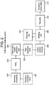
- Tile based rendering systems are well-known. These subdivide an image into a plurality of rectangular blocks or tiles. The way in which this is done and the subsequent texturing and the shading performed is shown schematically in figure 2 .
- a primitive/command fetch unit 201 retrieves command and primitive data from a memory and passes this to a geometry processing unit 202. This transforms the primitive and command data into screen space using well-known methods.
- This data is then supplied to a tiling unit 203 which inserts object data from the screen space geometry into object lists for each one of a set of defined rectangular regions or tiles.
- An object list for each tile contains primitives that exist wholly or partially in that tile. The list exists for every tile on the screen, although some object lists may have no data in them.
- These object lists are fetched by a tile parameter fetch unit 205 which supplies them tile by tile to a hidden surface removal unit (HSR) 206 which removes surfaces which will not contribute to the final scene (usually because they are obscured by another surface).
- HSR hidden surface removal unit
- the HSR unit processes each primitive in the tile and passes only data for visible pixels to a shading unit 208.
- the shading unit takes the data from the HSR and uses it to fetch textures using the texture unit 210 and applies shading to each pixel within a visible object using well-known techniques.
- the shading unit then feeds the textured and shaded data to an on chip tile buffer 212. As the data is temporarily stored in the on chip tile buffer external memory bandwidth associated with temporary storage eliminated.
- Preferred embodiments of the present invention provide a method and apparatus that enable a tile based rendering system to rasterise and store rendered texture surfaces only where they are to be used by subsequent renders. This is accomplished in an embodiment of the invention by performing the tiling phase as described above for all texture surfaces but deferring the rasterisation phase of those dynamically rendered texture surfaces to the point at which they are referenced.
- the rendering of the scene that uses the "demand based texture renders" e,g, 100 from figure 1
- the system can render one or more texture tiles at the point of reference into a small write back cache for immediate use within the main render. Due to the localised nature of the references it is highly likely that the rendered data will continue to reside within the cache subsystem for any tiles for which it is required, thereby substantially reducing the memory bandwidth associated with both the rendering of the textures and their subsequent use.
- Figure 3 illustrates the operation of demand mode texture rasterisation in a tile based system.
- An application 300 first generates geometry 305 for an image which is to be rendered to a texture as in 100 in Figure 1 .
- This geometry is processed at 310 using well known techniques to produce screen space geometry that is passed to a tiling unit 315 which generates tile screen space parameters 320 as described for a tile based rendering system.
- a valid flags table 358 This table is generally stored within memory and contains a status flag for each tile that indicates if it has been rendered, all flags are initially cleared to indicate that no tiles have been rendered. Each time a tile is rendered a flag corresponding to that tile is set.
- the application then switches to the rendering of a main scene at 330 by producing main scene geometry 335 which is then processed into screen space by geometry processor 340 and tiled at 345 to produce an object list for each tile.
- the resulting main scene parameters 350 are then rasterised a tile at a time at 355.
- the rasterisation hardware detects areas of dynamic texture e.g. an environment map that are required but are not present in the texture store. These correspond to texturing of the type discussed with reference to figure 1 above.
- the rasteriser determines if each texture tile (as shown in Figure 1 ) has been rendered by reading the tile valid flags 358.
- the rasteriser switches from rasterising the main scene to rasterising parameters for the texture tiles required by the texture render 320 that are associated with the required region.
- the subsequent rasterisation process 375 produces texture image data for T3 380 (from figure 1 ) which is written to a cache 360.
- a corresponding valid flag for the texture tile is then set and the rasterisation hardware then switches back to rasterising the main scene 355 at 385.
- This process is repeated for all regions of the scene which are found to be required from the dynamic texture. For example from figure 1 regions T3, T8, T9, T14, T15, T16, T21 and T22. It should be noted that the remaining regions of the dynamic texture are not rasterised saving significant memory bandwidth and processing overhead.
- the texture tile data written to the cache may either be written back to memory (not shown) or discarded when it is evicted from the cache 360. In the case where the data is discarded it may be re-created again in the future as described above if the tile (e.g. T3) is referenced again.
- This approach allows very large texture surfaces to be represented by the memory associated with the tiled geometry parameters only. Where texture data is discarded instead of being writtenback to memory the corresponding valid flags 358 are cleared to indicate that the texture is no longer present.
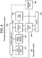
- FIG. 4 illustrates a system that implements tile based demand mode rendering of texture surfaces using dynamic textures as discussed above. It should be noted that the tiling/geometry processing units equivalent to these shown in figure 2 are not shown here.
- Tile parameter fetch unit 410 fetches the tiled parameter lists as per a normal tile based rendering system and passes the object data to the hidden surface removal unit (HSR) 420. This removes surfaces which will not contribute to the final scene (usually because they are obscured by another surface) using well known methods.
- HSR hidden surface removal unit
- the HSR unit processes each primitive in the tile and passes only data for surfaces visible at pixels to a shading unit 430.
- the shading unit 430 takes the objects from the HSR unit 420 and applies shading and texturing to each pixel within each visible object using well-known techniques, these technique include issuing texture requests to a texture sampling unit (TSU) 460.
- TSU texture sampling unit
- the TSU is illustrated in figure 5 .
- the texture address unit 500 takes texture sample requests and calculates the X and Y address for each texture fetch using well known methods.
- the X and Y address is passed to the tile address calculation unit 550 which determines the address of the tile that the requested texture fetches will reside within. This calculation typically removes low order bits from the X and Y addresses to form a tile X and Y address, these values are then multiplied together and added to a base address to form the address of a "Tile valid flag" stored in the tile valid table ( figure 4 480), which is stored in memory, it should be noted that other methods of address calculation could be used.
- the address of the valid flag is passed to the valid flag fetch unit 560 that retrieves the specified flag from valid flag table in memory.
- the valid flag fetch unit 560 could operate through a memory cache in order to improve its performance.
- the valid flag fetch unit also passes the valid flag to the address converter 520 which converts the X,Y address to a linear memory address using well known methods. If the valid flag indicates that a texture tile is not present then the address converter unit halts execution. If the valid flag indicates that a texture tile is present then the address converter unit passes the calculated texture address to the texture cache unit 530 which retrieves the texture data from either internal or external memory as necessary. The retrieved data is passed to the texture filtering unit 540 which filters the returned data using well known techniques, the resulting filtered data being passed back to the shading unit 430 in figure 4 .
- the "not present" signal 570 is sent to the context switch unit (CSU) 400 in figure 4 indicating that it needs to switch to rasterising a tile of the texture that "missed” i.e. the texture was not available. This occurs for dynamically rendered textures, such as environment textures.
- the CSU then instructs all units within the rasteriser to switch to rasterising the requested texture i.e. the missed texture tile. It should be noted that the CSU could rasterise a single missing tile or multiple tiles within the locality of the missing texture.
- the CSU 400 may be implemented as a hardware module, a separate programmable processor/micro controller or using a "Host" processor and device interrupts.
- a buffer 440 outputs each completed texture tile to memory via a cache 470.
- This cache will typically use the well known caching type of "write back caching" so that the data resides locally within the cache when the tiles indicated by the CSU have been rasterised.
- the CSU then updates the tile valid flags 480 for the tiles that it has rasterised to indicate that they are now present.
- the cache will now store the dynamically mapped texture required for rasterisation of tiles which were flagged as requiring that texture.
- the CSU switches the rasterisation units back to processing the original render and allows the address converter 520 in figure 5 to proceed to issue the texture address to the cache unit as described above.
- the texture tiles that were rasterised now sit locally within the cache any texture fetches for them now access the cache so reducing memory bandwidth associated with those fetches, i.e. dynamically mapped textures stored in the cache.
- the cache could be replaced with a memory buffer that discards tiles rather than writing them back to memory when making space for new tile data. In these circumstances the discarded tiles that are references again will need to be rasterised again using the above process.
Abstract
Description
- This invention relates to a three-dimensional computer graphics rendering system in particular to methods and apparatus associated with rendering of textures in a tile based rendering system.
- Within real time computer graphics it is common to perform renders to surfaces which can then be used as textures in subsequent renders i.e. the rendered surface becomes a new texture or a "Dynamically Rendered" texture. For example in order to render a scene that includes reflections of the scene it is common to first render the scene to an environment texture map. This map is then used during the shading of objects to produce a reflection of the environment on the objects. This may be used, for example to show a reflection in a mirrored building.
- In addition to environment mapping it is common for modern computer graphics applications to use a technique called shadow mapping. The shadow mapping technique renders the depth of objects from the perspective of light sources within the scene into texture maps. These texture maps are used during the subsequent rendering of objects to determine if each pixel is in shadow with respect to the light sources. This is done by comparing the depth of the object pixel being rendered to a depth that is stored at the equivalent location within a "shadow map" texture, for example if the depth of the object is greater than that in the shadow map then it is behind another object with respect to the light source and therefore the illuminating effect of the light source should not be applied during the rendering of that pixel. It is very common for textures associated with shadow maps to be very large e.g. 2048x2048 or greater, with larger texture sizes generally being required for higher quality rendering.
- It should be noted that there are many variations on the above techniques and that the above two are included as examples and that the scope of the invention is not limited to these techniques.
- In modern graphics applications these renders to textures and the subsequent reads from them can use a significant percentage of the available memory bandwidth to render a scene at interactive frame rates. Furthermore it is not unusual for much of the data rendered into these textures to not be subsequently used. For example
figure 1 illustrates a previously renderedtexture 100 subdivided into regions T0 to T23 and aregion 110 that maps a portion of thetexture 100 into thetriangle 120. As can be seen only tiles T3, T8, T9, T14 to T16, T21 and T22 of the previously rendered texture need to have been rasterised in order to satisfy the mapping of the texture to thetriangle 120. - Tile based rendering systems are well-known. These subdivide an image into a plurality of rectangular blocks or tiles. The way in which this is done and the subsequent texturing and the shading performed is shown schematically in
figure 2 . - Firstly, a primitive/
command fetch unit 201 retrieves command and primitive data from a memory and passes this to ageometry processing unit 202. This transforms the primitive and command data into screen space using well-known methods. - This data is then supplied to a
tiling unit 203 which inserts object data from the screen space geometry into object lists for each one of a set of defined rectangular regions or tiles. An object list for each tile contains primitives that exist wholly or partially in that tile. The list exists for every tile on the screen, although some object lists may have no data in them. These object lists are fetched by a tileparameter fetch unit 205 which supplies them tile by tile to a hidden surface removal unit (HSR) 206 which removes surfaces which will not contribute to the final scene (usually because they are obscured by another surface). The HSR unit processes each primitive in the tile and passes only data for visible pixels to ashading unit 208. - The shading unit takes the data from the HSR and uses it to fetch textures using the
texture unit 210 and applies shading to each pixel within a visible object using well-known techniques. The shading unit then feeds the textured and shaded data to an onchip tile buffer 212. As the data is temporarily stored in the on chip tile buffer external memory bandwidth associated with temporary storage eliminated. - Once each tile has been textured and shaded, the resultant data is written to an
external scene buffer 214. - Preferred embodiments of the present invention provide a method and apparatus that enable a tile based rendering system to rasterise and store rendered texture surfaces only where they are to be used by subsequent renders. This is accomplished in an embodiment of the invention by performing the tiling phase as described above for all texture surfaces but deferring the rasterisation phase of those dynamically rendered texture surfaces to the point at which they are referenced. As the rendering of the scene that uses the "demand based texture renders" (e,g, 100 from
figure 1 ) potentially only references a small area of each texture within each tile the system can render one or more texture tiles at the point of reference into a small write back cache for immediate use within the main render. Due to the localised nature of the references it is highly likely that the rendered data will continue to reside within the cache subsystem for any tiles for which it is required, thereby substantially reducing the memory bandwidth associated with both the rendering of the textures and their subsequent use. - Preferred embodiments of the invention will now be described in detail by way of example with reference to the accompanying drawings in which:
-
Figure 1 illustrates schematically how a small region of a previously rendered texture may be subsequently referenced for texturing an object; -
Figure 2 shows a schematic diagram of a known tile based rendering system as discussed above; -
Figure 3 illustrates the operation of demand based texture rendering embodying the invention; -
Figure 4 illustrates the modifications to a tile based rendering system for demand based texture rendering in an embodiment of the invention; and -
Figure 5 illustrates the modifications to the texture pipeline required to implement demand based texture rendering in an embodiment of the invention. -
Figure 3 illustrates the operation of demand mode texture rasterisation in a tile based system. Anapplication 300 first generatesgeometry 305 for an image which is to be rendered to a texture as in 100 inFigure 1 . This geometry is processed at 310 using well known techniques to produce screen space geometry that is passed to atiling unit 315 which generates tilescreen space parameters 320 as described for a tile based rendering system. It should be noted that the current state of each tile within the texture i.e. if it has been rendered is indicated by a valid flags table 358. This table is generally stored within memory and contains a status flag for each tile that indicates if it has been rendered, all flags are initially cleared to indicate that no tiles have been rendered. Each time a tile is rendered a flag corresponding to that tile is set. - The application then switches to the rendering of a main scene at 330 by producing
main scene geometry 335 which is then processed into screen space bygeometry processor 340 and tiled at 345 to produce an object list for each tile. The resultingmain scene parameters 350 are then rasterised a tile at a time at 355. During the rasterisation process the rasterisation hardware (not shown) detects areas of dynamic texture e.g. an environment map that are required but are not present in the texture store. These correspond to texturing of the type discussed with reference tofigure 1 above. The rasteriser determines if each texture tile (as shown inFigure 1 ) has been rendered by reading the tilevalid flags 358. When the rasterister determines that a texture tile has not yet been rendered the rasteriser switches from rasterising the main scene to rasterising parameters for the texture tiles required by thetexture render 320 that are associated with the required region. Thesubsequent rasterisation process 375 produces texture image data for T3 380 (fromfigure 1 ) which is written to acache 360. A corresponding valid flag for the texture tile is then set and the rasterisation hardware then switches back to rasterising themain scene 355 at 385. This process is repeated for all regions of the scene which are found to be required from the dynamic texture. For example fromfigure 1 regions T3, T8, T9, T14, T15, T16, T21 and T22. It should be noted that the remaining regions of the dynamic texture are not rasterised saving significant memory bandwidth and processing overhead. - It should be noted that the texture tile data written to the cache may either be written back to memory (not shown) or discarded when it is evicted from the
cache 360. In the case where the data is discarded it may be re-created again in the future as described above if the tile (e.g. T3) is referenced again. This approach allows very large texture surfaces to be represented by the memory associated with the tiled geometry parameters only. Where texture data is discarded instead of being writtenback to memory the correspondingvalid flags 358 are cleared to indicate that the texture is no longer present. -
Figure 4 illustrates a system that implements tile based demand mode rendering of texture surfaces using dynamic textures as discussed above. It should be noted that the tiling/geometry processing units equivalent to these shown infigure 2 are not shown here. Tile parameter fetchunit 410 fetches the tiled parameter lists as per a normal tile based rendering system and passes the object data to the hidden surface removal unit (HSR) 420. This removes surfaces which will not contribute to the final scene (usually because they are obscured by another surface) using well known methods. The HSR unit processes each primitive in the tile and passes only data for surfaces visible at pixels to ashading unit 430. - The
shading unit 430 takes the objects from theHSR unit 420 and applies shading and texturing to each pixel within each visible object using well-known techniques, these technique include issuing texture requests to a texture sampling unit (TSU) 460. - The TSU is illustrated in
figure 5 . Thetexture address unit 500 takes texture sample requests and calculates the X and Y address for each texture fetch using well known methods. The X and Y address is passed to the tileaddress calculation unit 550 which determines the address of the tile that the requested texture fetches will reside within. This calculation typically removes low order bits from the X and Y addresses to form a tile X and Y address, these values are then multiplied together and added to a base address to form the address of a "Tile valid flag" stored in the tile valid table (figure 4 480), which is stored in memory, it should be noted that other methods of address calculation could be used. The address of the valid flag is passed to the valid flag fetchunit 560 that retrieves the specified flag from valid flag table in memory. This flag is then emitted as the "Not present"signal 570. It should be noted that the valid flag fetchunit 560 could operate through a memory cache in order to improve its performance. The valid flag fetch unit also passes the valid flag to theaddress converter 520 which converts the X,Y address to a linear memory address using well known methods. If the valid flag indicates that a texture tile is not present then the address converter unit halts execution. If the valid flag indicates that a texture tile is present then the address converter unit passes the calculated texture address to thetexture cache unit 530 which retrieves the texture data from either internal or external memory as necessary. The retrieved data is passed to thetexture filtering unit 540 which filters the returned data using well known techniques, the resulting filtered data being passed back to theshading unit 430 infigure 4 . - If the flag indicates that the texture tile hasn't already been rasterised the "not present"
signal 570 is sent to the context switch unit (CSU) 400 infigure 4 indicating that it needs to switch to rasterising a tile of the texture that "missed" i.e. the texture was not available. This occurs for dynamically rendered textures, such as environment textures. - The CSU then instructs all units within the rasteriser to switch to rasterising the requested texture i.e. the missed texture tile. It should be noted that the CSU could rasterise a single missing tile or multiple tiles within the locality of the missing texture. The
CSU 400 may be implemented as a hardware module, a separate programmable processor/micro controller or using a "Host" processor and device interrupts. - As the system rasterises each tile indicated by the CSU a
buffer 440 outputs each completed texture tile to memory via acache 470. This cache will typically use the well known caching type of "write back caching" so that the data resides locally within the cache when the tiles indicated by the CSU have been rasterised. The CSU then updates the tilevalid flags 480 for the tiles that it has rasterised to indicate that they are now present. The cache will now store the dynamically mapped texture required for rasterisation of tiles which were flagged as requiring that texture. - On completion of the rasterisation process for the required tile(s) the CSU switches the rasterisation units back to processing the original render and allows the
address converter 520 infigure 5 to proceed to issue the texture address to the cache unit as described above. As the texture tiles that were rasterised now sit locally within the cache any texture fetches for them now access the cache so reducing memory bandwidth associated with those fetches, i.e. dynamically mapped textures stored in the cache. - It should be noted that the cache could be replaced with a memory buffer that discards tiles rather than writing them back to memory when making space for new tile data. In these circumstances the discarded tiles that are references again will need to be rasterised again using the above process.
-
- 1. A method for shading and texturing computer graphic images in a tile based rendering system using dynamically rendered textures, comprising the steps of;
- deriving screen space geometry for a dynamically rendered texture;
- passing the dynamically rendered texture screen space geometry to a tiling unit;
- deriving screen space geometry for a scene that references the dynamically rendered texture;
- passing the screen space geometry for the scene to a tiling unit;
- rendering tiles from the tiling unit using object data derived from the screen space geometry;
- detecting references to area of a dynamically rendered textures that have yet to be rendered;
- dynamically rendering texture data for tiles corresponding to those areas detected as yet to be rendered with the dynamically rendered texture.
- 2. A method according to paragraph 1 in which dynamically rendered texture data is stored in a texture cache.
- 3. A method according to paragraph 1 including the step of determining whether a required dynamically rendered texture has been previously rendered.
- 4. Apparatus for shading and texturing computer graphic images in a tile based rendering system using dynamically rendered textures comprising;
- means for deriving screen space geometry;
- a tiling unit receiving screen space geometry;
- means for rendering tiles from the tiling unit using object data derived from the screen space for geometry;
- means for detecting areas of dynamically rendered textures intersecting tiles and required to texture those tiles;
- means for deriving dynamically rendered texture data for use in rendering the intersecting tiles and to be used by the rendering means for rendering the intersected tiles; and
- characterised in that the means for deriving dynamically rendered texture data only it derives this data for texture tiles which intersect an object that require the texture to be applied to it by the rendering means.
- 5. A method according to paragraph 4 or 5 in which a texture cache stores dynamically rendered texture data.
- 6. A method according to paragraph 3 including means for determining whether a required dynamically rendered texture has been previously derived.
- 7. A method for shading and texturing computer graphic images in a tile based rendering system substantially as herein described.
- 8. Apparatus for shading and texturing computer graphic images in a tile based rendering system substantially as herein described with reference to
figures 4 and5 of the drawings.
[END OF DESCRIPTION]
Claims (14)
- A method for shading and texturing computer graphic images in a tile based rendering system using dynamically rendered textures comprising the steps of:deriving screen space geometry for a texture to be dynamically rendered;passing the screen space geometry for the texture to a tiling unit, to generate texture parameters for each of a plurality of texture tiles;deriving screen space geometry for a scene that references the texture to be dynamically rendered;passing the screen space geometry for the scene to the tiling unit, to generate an object list for each of a plurality of scene tiles; andrendering a scene tile from the tiling unit using the object list, the rendering comprising:issuing a texture request for the texture to a texture sampling unit;calculating an X and Y address for texture fetch;determining which texture tile the texture fetch is within;reading a corresponding valid flag for the texture tile from a table in memory to determine whether the texture tile has been rendered; anddynamically rendering texture data for the texture tile if the valid flag indicates that the texture tile has not been rendered.
- A method according to claim 1 comprising writing the dynamically rendered texture data to memory via a cache.
- A method according to claim 2, wherein the cache is a write-back cache.
- A method according to claim 2 or claim 3, comprising switching back to rendering the scene tile after writing the dynamically rendered texture data to memory via the cache.
- A method according to any preceding claim, comprising setting the corresponding valid flag for the texture tile when the texture tile has been rendered.
- A method according to any preceding claim, wherein determining which texture tile the texture fetch is within comprises determining, using a tile address calculation unit, the address of the tile that the texture fetch is within based upon the X and Y address.
- A method according to any preceding claim, wherein determining which texture tile the texture fetch is within comprises removing low order bits from the X and Y address to form a tile X and Y address, multiplying these values together and adding the result to a base address to form an address of the valid flag.
- Apparatus for shading and texturing computer graphic images in a tile based rendering system using dynamically rendered textures comprising:means for deriving screen space geometry for a texture to be dynamically rendered;means for passing the screen space geometry for the texture to a tiling unit, to generate texture parameters for each of a plurality of texture tiles;means for deriving screen space geometry for a scene that references the texture to be dynamically rendered;means for passing the screen space geometry for the scene to the tiling unit, to generate an object list for each of a plurality of scene tiles; andmeans for rendering a scene tile from the tiling unit using the object list, the rendering comprising:issuing a texture request for the texture to a texture sampling unit;calculating an X and Y address for texture fetch;determining which texture tile the texture fetch is within;reading a corresponding valid flag for the texture tile from a table in memory to determine whether the texture tile has been rendered; anddynamically rendering texture data for the texture tile if the valid flag indicates that the texture tile has not been rendered.
- An apparatus according to claim 8 comprising means for writing the dynamically rendered texture data to memory via a cache.
- An apparatus according to claim 9, wherein the cache is a write-back cache.
- An apparatus according to claim 9 or claim 10, comprising switching back to rendering the scene tile after writing the dynamically rendered texture data to memory via the cache.
- An apparatus according to any of claims 8 to 11, comprising setting the corresponding valid flag for the texture tile when the texture tile has been rendered.
- An apparatus according to any of claims 8 to 12, wherein determining which texture tile the texture fetch is within comprises determining, using a tile address calculation unit, the address of the tile that the texture fetch is within based upon the X and Y address.
- An apparatus according to any of claims 8 to 13, wherein determining which texture tile the texture fetch is within comprises removing low order bits from the X and Y address to form a tile X and Y address, multiplying these values together and adding the result to a base address to form an address of the valid flag.
Applications Claiming Priority (3)
| Application Number | Priority Date | Filing Date | Title |
|---|---|---|---|
| GB1004676.1A GB2478909B (en) | 2010-03-19 | 2010-03-19 | Demand based texture rendering in a tile based rendering system |
| PCT/GB2011/000385 WO2011114112A1 (en) | 2010-03-19 | 2011-03-18 | Demand based texture rendering in a tile based rendering system |
| EP11716975.5A EP2548177B1 (en) | 2010-03-19 | 2011-03-18 | Demand based texture rendering in a tile based rendering system |
Related Parent Applications (2)
| Application Number | Title | Priority Date | Filing Date |
|---|---|---|---|
| EP11716975.5A Division EP2548177B1 (en) | 2010-03-19 | 2011-03-18 | Demand based texture rendering in a tile based rendering system |
| EP11716975.5A Division-Into EP2548177B1 (en) | 2010-03-19 | 2011-03-18 | Demand based texture rendering in a tile based rendering system |
Publications (2)
| Publication Number | Publication Date |
|---|---|
| EP3144897A1 true EP3144897A1 (en) | 2017-03-22 |
| EP3144897B1 EP3144897B1 (en) | 2020-01-01 |
Family
ID=42228050
Family Applications (2)
| Application Number | Title | Priority Date | Filing Date |
|---|---|---|---|
| EP16197248.4A Active EP3144897B1 (en) | 2010-03-19 | 2011-03-18 | Demand based texture rendering in a tile based rendering system |
| EP11716975.5A Active EP2548177B1 (en) | 2010-03-19 | 2011-03-18 | Demand based texture rendering in a tile based rendering system |
Family Applications After (1)
| Application Number | Title | Priority Date | Filing Date |
|---|---|---|---|
| EP11716975.5A Active EP2548177B1 (en) | 2010-03-19 | 2011-03-18 | Demand based texture rendering in a tile based rendering system |
Country Status (5)
| Country | Link |
|---|---|
| US (1) | US20110254852A1 (en) |
| EP (2) | EP3144897B1 (en) |
| CN (2) | CN106296790B (en) |
| GB (1) | GB2478909B (en) |
| WO (1) | WO2011114112A1 (en) |
Families Citing this family (22)
| Publication number | Priority date | Publication date | Assignee | Title |
|---|---|---|---|---|
| US9069433B2 (en) * | 2012-02-10 | 2015-06-30 | Randall Hunt | Method and apparatus for generating chain-link fence design |
| GB2506706B (en) | 2013-04-02 | 2014-09-03 | Imagination Tech Ltd | Tile-based graphics |
| GB2520366B (en) | 2013-12-13 | 2015-12-09 | Imagination Tech Ltd | Primitive processing in a graphics processing system |
| GB2520365B (en) | 2013-12-13 | 2015-12-09 | Imagination Tech Ltd | Primitive processing in a graphics processing system |
| CN103995684B (en) * | 2014-05-07 | 2017-01-25 | 广州瀚阳工程咨询有限公司 | Method and system for synchronously processing and displaying mass images under ultrahigh resolution platform |
| US9760968B2 (en) | 2014-05-09 | 2017-09-12 | Samsung Electronics Co., Ltd. | Reduction of graphical processing through coverage testing |
| GB2526598B (en) | 2014-05-29 | 2018-11-28 | Imagination Tech Ltd | Allocation of primitives to primitive blocks |
| GB2524120B (en) * | 2014-06-17 | 2016-03-02 | Imagination Tech Ltd | Assigning primitives to tiles in a graphics processing system |
| GB2524121B (en) | 2014-06-17 | 2016-03-02 | Imagination Tech Ltd | Assigning primitives to tiles in a graphics processing system |
| US9842428B2 (en) | 2014-06-27 | 2017-12-12 | Samsung Electronics Co., Ltd. | Dynamically optimized deferred rendering pipeline |
| CN105321196A (en) * | 2014-07-21 | 2016-02-10 | 上海羽舟网络科技有限公司 | 3D image processing method and system |
| US9232156B1 (en) | 2014-09-22 | 2016-01-05 | Freescale Semiconductor, Inc. | Video processing device and method |
| GB2534567B (en) * | 2015-01-27 | 2017-04-19 | Imagination Tech Ltd | Processing primitives which have unresolved fragments in a graphics processing system |
| GB2546811B (en) | 2016-02-01 | 2020-04-15 | Imagination Tech Ltd | Frustum rendering |
| GB2546810B (en) | 2016-02-01 | 2019-10-16 | Imagination Tech Ltd | Sparse rendering |
| GB201713052D0 (en) * | 2017-08-15 | 2017-09-27 | Imagination Tech Ltd | Single pass rendering for head mounted displays |
| US10424074B1 (en) | 2018-07-03 | 2019-09-24 | Nvidia Corporation | Method and apparatus for obtaining sampled positions of texturing operations |
| US10672185B2 (en) | 2018-07-13 | 2020-06-02 | Nvidia Corporation | Multi-rate shading using replayed screen space tiles |
| US10950305B1 (en) * | 2018-11-02 | 2021-03-16 | Facebook Technologies, Llc | Selective pixel output |
| CN110866965A (en) * | 2019-11-14 | 2020-03-06 | 珠海金山网络游戏科技有限公司 | Mapping drawing method and device for three-dimensional model |
| CN110990104B (en) * | 2019-12-06 | 2023-04-11 | 珠海金山数字网络科技有限公司 | Texture rendering method and device based on Unity3D |
| WO2022131949A1 (en) * | 2020-12-14 | 2022-06-23 | Huawei Technologies Co., Ltd. | A device for performing a recursive rasterization |
Citations (1)
| Publication number | Priority date | Publication date | Assignee | Title |
|---|---|---|---|---|
| US20090147017A1 (en) * | 2007-12-06 | 2009-06-11 | Via Technologies, Inc. | Shader Processing Systems and Methods |
Family Cites Families (8)
| Publication number | Priority date | Publication date | Assignee | Title |
|---|---|---|---|---|
| US4225861A (en) * | 1978-12-18 | 1980-09-30 | International Business Machines Corporation | Method and means for texture display in raster scanned color graphic |
| US5371839A (en) * | 1987-02-27 | 1994-12-06 | Hitachi, Ltd. | Rendering processor |
| US6795072B1 (en) * | 1999-08-12 | 2004-09-21 | Broadcom Corporation | Method and system for rendering macropixels in a graphical image |
| US6859209B2 (en) * | 2001-05-18 | 2005-02-22 | Sun Microsystems, Inc. | Graphics data accumulation for improved multi-layer texture performance |
| US6914610B2 (en) * | 2001-05-18 | 2005-07-05 | Sun Microsystems, Inc. | Graphics primitive size estimation and subdivision for use with a texture accumulation buffer |
| US8089486B2 (en) * | 2005-03-21 | 2012-01-03 | Qualcomm Incorporated | Tiled prefetched and cached depth buffer |
| GB2452300B (en) * | 2007-08-30 | 2009-11-04 | Imagination Tech Ltd | Predicated geometry processing in a tile based rendering system |
| GB0810205D0 (en) * | 2008-06-04 | 2008-07-09 | Advanced Risc Mach Ltd | Graphics processing systems |
-
2010
- 2010-03-19 GB GB1004676.1A patent/GB2478909B/en active Active
-
2011
- 2011-03-18 EP EP16197248.4A patent/EP3144897B1/en active Active
- 2011-03-18 CN CN201610652483.2A patent/CN106296790B/en active Active
- 2011-03-18 US US13/065,338 patent/US20110254852A1/en not_active Abandoned
- 2011-03-18 WO PCT/GB2011/000385 patent/WO2011114112A1/en active Application Filing
- 2011-03-18 CN CN201180014841.2A patent/CN102822871B/en active Active
- 2011-03-18 EP EP11716975.5A patent/EP2548177B1/en active Active
Patent Citations (1)
| Publication number | Priority date | Publication date | Assignee | Title |
|---|---|---|---|---|
| US20090147017A1 (en) * | 2007-12-06 | 2009-06-11 | Via Technologies, Inc. | Shader Processing Systems and Methods |
Non-Patent Citations (2)
| Title |
|---|
| CAPIN T ET AL: "The State of the Art in Mobile Graphics Research", IEEE COMPUTER GRAPHICS AND APPLICATIONS, IEEE SERVICE CENTER, NEW YORK, NY, US, vol. 28, no. 4, 1 July 2008 (2008-07-01), pages 74 - 84, XP011229506, ISSN: 0272-1716, DOI: 10.1109/MCG.2008.83 * |
| DANA COBZAS, KEITH YEREX AND MARTING JÄGERSAND: "Dynamic textures for image-based rendering of fine-scale 3D structure and animation of non-rigid motion", EUROGRAPHICS 2002, vol. 21, no. 3, 2002 - 2002, pages 493 - 502, XP002644684 * |
Also Published As
| Publication number | Publication date |
|---|---|
| CN102822871A (en) | 2012-12-12 |
| GB2478909B (en) | 2013-11-06 |
| CN102822871B (en) | 2016-09-07 |
| EP3144897B1 (en) | 2020-01-01 |
| EP2548177A1 (en) | 2013-01-23 |
| GB201004676D0 (en) | 2010-05-05 |
| GB2478909A (en) | 2011-09-28 |
| CN106296790B (en) | 2020-02-14 |
| CN106296790A (en) | 2017-01-04 |
| EP2548177B1 (en) | 2016-12-14 |
| WO2011114112A1 (en) | 2011-09-22 |
| US20110254852A1 (en) | 2011-10-20 |
Similar Documents
| Publication | Publication Date | Title |
|---|---|---|
| EP2548177B1 (en) | Demand based texture rendering in a tile based rendering system | |
| US11657565B2 (en) | Hidden culling in tile-based computer generated images | |
| JP5847159B2 (en) | Surface patch tessellation in tile-based rendering systems | |
| US7042462B2 (en) | Pixel cache, 3D graphics accelerator using the same, and method therefor | |
| JP5296169B2 (en) | Tiled prefetch and cached depth buffer | |
| EP2279495B1 (en) | Untransformed display lists in a tile based rendering system | |
| KR101281258B1 (en) | Graphics processing unit with deferred vertex shading | |
| US7068272B1 (en) | System, method and article of manufacture for Z-value and stencil culling prior to rendering in a computer graphics processing pipeline | |
| JP4938850B2 (en) | Graphic processing unit with extended vertex cache | |
| US6972769B1 (en) | Vertex texture cache returning hits out of order | |
| US7898551B2 (en) | Systems and methods for performing a bank swizzle operation to reduce bank collisions | |
| KR100703709B1 (en) | Apparatus and method for processing graphics, and computer readable medium storing the same | |
| GB2500284A (en) | Object list tile based computer graphics using modified primitives | |
| GB2460545A (en) | Determination of data availability in memory and identification of data not needed for rendering | |
| GB2509113A (en) | Tessellating Patches Of Surface Data In Tile Based Computer Graphics Rendering | |
| US20090225098A1 (en) | Guard Band Clipping Systems and Methods | |
| US7382377B1 (en) | Render to texture cull | |
| Smit et al. | A shared-scene-graph image-warping architecture for VR: Low latency versus image quality | |
| WO2010041215A1 (en) | Geometry primitive shading graphics system | |
| GB2475375A (en) | Dynamic Graphics Rendering Process |
Legal Events
| Date | Code | Title | Description |
|---|---|---|---|
| PUAI | Public reference made under article 153(3) epc to a published international application that has entered the european phase |
Free format text: ORIGINAL CODE: 0009012 |
|
| STAA | Information on the status of an ep patent application or granted ep patent |
Free format text: STATUS: THE APPLICATION HAS BEEN PUBLISHED |
|
| AC | Divisional application: reference to earlier application |
Ref document number: 2548177 Country of ref document: EP Kind code of ref document: P |
|
| AK | Designated contracting states |
Kind code of ref document: A1 Designated state(s): AL AT BE BG CH CY CZ DE DK EE ES FI FR GB GR HR HU IE IS IT LI LT LU LV MC MK MT NL NO PL PT RO RS SE SI SK SM TR |
|
| STAA | Information on the status of an ep patent application or granted ep patent |
Free format text: STATUS: REQUEST FOR EXAMINATION WAS MADE |
|
| 17P | Request for examination filed |
Effective date: 20170921 |
|
| RBV | Designated contracting states (corrected) |
Designated state(s): AL AT BE BG CH CY CZ DE DK EE ES FI FR GB GR HR HU IE IS IT LI LT LU LV MC MK MT NL NO PL PT RO RS SE SI SK SM TR |
|
| GRAP | Despatch of communication of intention to grant a patent |
Free format text: ORIGINAL CODE: EPIDOSNIGR1 |
|
| STAA | Information on the status of an ep patent application or granted ep patent |
Free format text: STATUS: GRANT OF PATENT IS INTENDED |
|
| INTG | Intention to grant announced |
Effective date: 20190808 |
|
| GRAS | Grant fee paid |
Free format text: ORIGINAL CODE: EPIDOSNIGR3 |
|
| GRAA | (expected) grant |
Free format text: ORIGINAL CODE: 0009210 |
|
| STAA | Information on the status of an ep patent application or granted ep patent |
Free format text: STATUS: THE PATENT HAS BEEN GRANTED |
|
| AC | Divisional application: reference to earlier application |
Ref document number: 2548177 Country of ref document: EP Kind code of ref document: P |
|
| AK | Designated contracting states |
Kind code of ref document: B1 Designated state(s): AL AT BE BG CH CY CZ DE DK EE ES FI FR GB GR HR HU IE IS IT LI LT LU LV MC MK MT NL NO PL PT RO RS SE SI SK SM TR |
|
| RAP1 | Party data changed (applicant data changed or rights of an application transferred) |
Owner name: IMAGINATION TECHNOLOGIES LIMITED |
|
| REG | Reference to a national code |
Ref country code: GB Ref legal event code: FG4D |
|
| REG | Reference to a national code |
Ref country code: CH Ref legal event code: EP Ref country code: AT Ref legal event code: REF Ref document number: 1220761 Country of ref document: AT Kind code of ref document: T Effective date: 20200115 |
|
| REG | Reference to a national code |
Ref country code: IE Ref legal event code: FG4D |
|
| REG | Reference to a national code |
Ref country code: DE Ref legal event code: R096 Ref document number: 602011064418 Country of ref document: DE |
|
| REG | Reference to a national code |
Ref country code: NL Ref legal event code: MP Effective date: 20200101 |
|
| REG | Reference to a national code |
Ref country code: LT Ref legal event code: MG4D |
|
| PG25 | Lapsed in a contracting state [announced via postgrant information from national office to epo] |
Ref country code: CZ Free format text: LAPSE BECAUSE OF FAILURE TO SUBMIT A TRANSLATION OF THE DESCRIPTION OR TO PAY THE FEE WITHIN THE PRESCRIBED TIME-LIMIT Effective date: 20200101 Ref country code: PT Free format text: LAPSE BECAUSE OF FAILURE TO SUBMIT A TRANSLATION OF THE DESCRIPTION OR TO PAY THE FEE WITHIN THE PRESCRIBED TIME-LIMIT Effective date: 20200527 Ref country code: NO Free format text: LAPSE BECAUSE OF FAILURE TO SUBMIT A TRANSLATION OF THE DESCRIPTION OR TO PAY THE FEE WITHIN THE PRESCRIBED TIME-LIMIT Effective date: 20200401 Ref country code: LT Free format text: LAPSE BECAUSE OF FAILURE TO SUBMIT A TRANSLATION OF THE DESCRIPTION OR TO PAY THE FEE WITHIN THE PRESCRIBED TIME-LIMIT Effective date: 20200101 Ref country code: RS Free format text: LAPSE BECAUSE OF FAILURE TO SUBMIT A TRANSLATION OF THE DESCRIPTION OR TO PAY THE FEE WITHIN THE PRESCRIBED TIME-LIMIT Effective date: 20200101 Ref country code: NL Free format text: LAPSE BECAUSE OF FAILURE TO SUBMIT A TRANSLATION OF THE DESCRIPTION OR TO PAY THE FEE WITHIN THE PRESCRIBED TIME-LIMIT Effective date: 20200101 Ref country code: FI Free format text: LAPSE BECAUSE OF FAILURE TO SUBMIT A TRANSLATION OF THE DESCRIPTION OR TO PAY THE FEE WITHIN THE PRESCRIBED TIME-LIMIT Effective date: 20200101 |
|
| PG25 | Lapsed in a contracting state [announced via postgrant information from national office to epo] |
Ref country code: IS Free format text: LAPSE BECAUSE OF FAILURE TO SUBMIT A TRANSLATION OF THE DESCRIPTION OR TO PAY THE FEE WITHIN THE PRESCRIBED TIME-LIMIT Effective date: 20200501 Ref country code: BG Free format text: LAPSE BECAUSE OF FAILURE TO SUBMIT A TRANSLATION OF THE DESCRIPTION OR TO PAY THE FEE WITHIN THE PRESCRIBED TIME-LIMIT Effective date: 20200401 Ref country code: GR Free format text: LAPSE BECAUSE OF FAILURE TO SUBMIT A TRANSLATION OF THE DESCRIPTION OR TO PAY THE FEE WITHIN THE PRESCRIBED TIME-LIMIT Effective date: 20200402 Ref country code: HR Free format text: LAPSE BECAUSE OF FAILURE TO SUBMIT A TRANSLATION OF THE DESCRIPTION OR TO PAY THE FEE WITHIN THE PRESCRIBED TIME-LIMIT Effective date: 20200101 Ref country code: LV Free format text: LAPSE BECAUSE OF FAILURE TO SUBMIT A TRANSLATION OF THE DESCRIPTION OR TO PAY THE FEE WITHIN THE PRESCRIBED TIME-LIMIT Effective date: 20200101 Ref country code: SE Free format text: LAPSE BECAUSE OF FAILURE TO SUBMIT A TRANSLATION OF THE DESCRIPTION OR TO PAY THE FEE WITHIN THE PRESCRIBED TIME-LIMIT Effective date: 20200101 |
|
| REG | Reference to a national code |
Ref country code: DE Ref legal event code: R097 Ref document number: 602011064418 Country of ref document: DE |
|
| PG25 | Lapsed in a contracting state [announced via postgrant information from national office to epo] |
Ref country code: MC Free format text: LAPSE BECAUSE OF FAILURE TO SUBMIT A TRANSLATION OF THE DESCRIPTION OR TO PAY THE FEE WITHIN THE PRESCRIBED TIME-LIMIT Effective date: 20200101 Ref country code: ES Free format text: LAPSE BECAUSE OF FAILURE TO SUBMIT A TRANSLATION OF THE DESCRIPTION OR TO PAY THE FEE WITHIN THE PRESCRIBED TIME-LIMIT Effective date: 20200101 Ref country code: SK Free format text: LAPSE BECAUSE OF FAILURE TO SUBMIT A TRANSLATION OF THE DESCRIPTION OR TO PAY THE FEE WITHIN THE PRESCRIBED TIME-LIMIT Effective date: 20200101 Ref country code: RO Free format text: LAPSE BECAUSE OF FAILURE TO SUBMIT A TRANSLATION OF THE DESCRIPTION OR TO PAY THE FEE WITHIN THE PRESCRIBED TIME-LIMIT Effective date: 20200101 Ref country code: SM Free format text: LAPSE BECAUSE OF FAILURE TO SUBMIT A TRANSLATION OF THE DESCRIPTION OR TO PAY THE FEE WITHIN THE PRESCRIBED TIME-LIMIT Effective date: 20200101 Ref country code: EE Free format text: LAPSE BECAUSE OF FAILURE TO SUBMIT A TRANSLATION OF THE DESCRIPTION OR TO PAY THE FEE WITHIN THE PRESCRIBED TIME-LIMIT Effective date: 20200101 Ref country code: DK Free format text: LAPSE BECAUSE OF FAILURE TO SUBMIT A TRANSLATION OF THE DESCRIPTION OR TO PAY THE FEE WITHIN THE PRESCRIBED TIME-LIMIT Effective date: 20200101 |
|
| REG | Reference to a national code |
Ref country code: CH Ref legal event code: PL |
|
| PLBE | No opposition filed within time limit |
Free format text: ORIGINAL CODE: 0009261 |
|
| STAA | Information on the status of an ep patent application or granted ep patent |
Free format text: STATUS: NO OPPOSITION FILED WITHIN TIME LIMIT |
|
| REG | Reference to a national code |
Ref country code: AT Ref legal event code: MK05 Ref document number: 1220761 Country of ref document: AT Kind code of ref document: T Effective date: 20200101 |
|
| 26N | No opposition filed |
Effective date: 20201002 |
|
| REG | Reference to a national code |
Ref country code: BE Ref legal event code: MM Effective date: 20200331 |
|
| PG25 | Lapsed in a contracting state [announced via postgrant information from national office to epo] |
Ref country code: LU Free format text: LAPSE BECAUSE OF NON-PAYMENT OF DUE FEES Effective date: 20200318 |
|
| PG25 | Lapsed in a contracting state [announced via postgrant information from national office to epo] |
Ref country code: IT Free format text: LAPSE BECAUSE OF FAILURE TO SUBMIT A TRANSLATION OF THE DESCRIPTION OR TO PAY THE FEE WITHIN THE PRESCRIBED TIME-LIMIT Effective date: 20200101 Ref country code: IE Free format text: LAPSE BECAUSE OF NON-PAYMENT OF DUE FEES Effective date: 20200318 Ref country code: CH Free format text: LAPSE BECAUSE OF NON-PAYMENT OF DUE FEES Effective date: 20200331 Ref country code: AT Free format text: LAPSE BECAUSE OF FAILURE TO SUBMIT A TRANSLATION OF THE DESCRIPTION OR TO PAY THE FEE WITHIN THE PRESCRIBED TIME-LIMIT Effective date: 20200101 Ref country code: LI Free format text: LAPSE BECAUSE OF NON-PAYMENT OF DUE FEES Effective date: 20200331 |
|
| PG25 | Lapsed in a contracting state [announced via postgrant information from national office to epo] |
Ref country code: BE Free format text: LAPSE BECAUSE OF NON-PAYMENT OF DUE FEES Effective date: 20200331 Ref country code: PL Free format text: LAPSE BECAUSE OF FAILURE TO SUBMIT A TRANSLATION OF THE DESCRIPTION OR TO PAY THE FEE WITHIN THE PRESCRIBED TIME-LIMIT Effective date: 20200101 Ref country code: SI Free format text: LAPSE BECAUSE OF FAILURE TO SUBMIT A TRANSLATION OF THE DESCRIPTION OR TO PAY THE FEE WITHIN THE PRESCRIBED TIME-LIMIT Effective date: 20200101 |
|
| PG25 | Lapsed in a contracting state [announced via postgrant information from national office to epo] |
Ref country code: TR Free format text: LAPSE BECAUSE OF FAILURE TO SUBMIT A TRANSLATION OF THE DESCRIPTION OR TO PAY THE FEE WITHIN THE PRESCRIBED TIME-LIMIT Effective date: 20200101 Ref country code: MT Free format text: LAPSE BECAUSE OF FAILURE TO SUBMIT A TRANSLATION OF THE DESCRIPTION OR TO PAY THE FEE WITHIN THE PRESCRIBED TIME-LIMIT Effective date: 20200101 Ref country code: CY Free format text: LAPSE BECAUSE OF FAILURE TO SUBMIT A TRANSLATION OF THE DESCRIPTION OR TO PAY THE FEE WITHIN THE PRESCRIBED TIME-LIMIT Effective date: 20200101 |
|
| PG25 | Lapsed in a contracting state [announced via postgrant information from national office to epo] |
Ref country code: MK Free format text: LAPSE BECAUSE OF FAILURE TO SUBMIT A TRANSLATION OF THE DESCRIPTION OR TO PAY THE FEE WITHIN THE PRESCRIBED TIME-LIMIT Effective date: 20200101 Ref country code: AL Free format text: LAPSE BECAUSE OF FAILURE TO SUBMIT A TRANSLATION OF THE DESCRIPTION OR TO PAY THE FEE WITHIN THE PRESCRIBED TIME-LIMIT Effective date: 20200101 |
|
| PGFP | Annual fee paid to national office [announced via postgrant information from national office to epo] |
Ref country code: FR Payment date: 20230324 Year of fee payment: 13 |
|
| PGFP | Annual fee paid to national office [announced via postgrant information from national office to epo] |
Ref country code: GB Payment date: 20230322 Year of fee payment: 13 Ref country code: DE Payment date: 20230321 Year of fee payment: 13 |
|
| P01 | Opt-out of the competence of the unified patent court (upc) registered |
Effective date: 20230517 |