EP3144884A1 - Représentation de données de champ lumineux - Google Patents
Représentation de données de champ lumineux Download PDFInfo
- Publication number
- EP3144884A1 EP3144884A1 EP15306434.0A EP15306434A EP3144884A1 EP 3144884 A1 EP3144884 A1 EP 3144884A1 EP 15306434 A EP15306434 A EP 15306434A EP 3144884 A1 EP3144884 A1 EP 3144884A1
- Authority
- EP
- European Patent Office
- Prior art keywords
- data
- light field
- rays
- ray
- ray diagram
- Prior art date
- Legal status (The legal status is an assumption and is not a legal conclusion. Google has not performed a legal analysis and makes no representation as to the accuracy of the status listed.)
- Withdrawn
Links
- 238000010586 diagram Methods 0.000 claims abstract description 66
- 238000000034 method Methods 0.000 claims abstract description 26
- 238000012545 processing Methods 0.000 claims description 16
- 229910052704 radon Inorganic materials 0.000 claims description 13
- SYUHGPGVQRZVTB-UHFFFAOYSA-N radon atom Chemical compound [Rn] SYUHGPGVQRZVTB-UHFFFAOYSA-N 0.000 claims description 13
- 239000011159 matrix material Substances 0.000 claims description 12
- 238000004422 calculation algorithm Methods 0.000 claims description 8
- 238000009877 rendering Methods 0.000 claims description 8
- 239000003086 colorant Substances 0.000 claims description 3
- 238000004590 computer program Methods 0.000 claims description 3
- 238000003384 imaging method Methods 0.000 claims description 3
- 230000014509 gene expression Effects 0.000 description 12
- 230000003287 optical effect Effects 0.000 description 10
- 238000004891 communication Methods 0.000 description 6
- 230000006870 function Effects 0.000 description 6
- 239000000463 material Substances 0.000 description 4
- 238000004364 calculation method Methods 0.000 description 3
- 238000005516 engineering process Methods 0.000 description 3
- 238000005070 sampling Methods 0.000 description 3
- PCTMTFRHKVHKIS-BMFZQQSSSA-N (1s,3r,4e,6e,8e,10e,12e,14e,16e,18s,19r,20r,21s,25r,27r,30r,31r,33s,35r,37s,38r)-3-[(2r,3s,4s,5s,6r)-4-amino-3,5-dihydroxy-6-methyloxan-2-yl]oxy-19,25,27,30,31,33,35,37-octahydroxy-18,20,21-trimethyl-23-oxo-22,39-dioxabicyclo[33.3.1]nonatriaconta-4,6,8,10 Chemical compound C1C=C2C[C@@H](OS(O)(=O)=O)CC[C@]2(C)[C@@H]2[C@@H]1[C@@H]1CC[C@H]([C@H](C)CCCC(C)C)[C@@]1(C)CC2.O[C@H]1[C@@H](N)[C@H](O)[C@@H](C)O[C@H]1O[C@H]1/C=C/C=C/C=C/C=C/C=C/C=C/C=C/[C@H](C)[C@@H](O)[C@@H](C)[C@H](C)OC(=O)C[C@H](O)C[C@H](O)CC[C@@H](O)[C@H](O)C[C@H](O)C[C@](O)(C[C@H](O)[C@H]2C(O)=O)O[C@H]2C1 PCTMTFRHKVHKIS-BMFZQQSSSA-N 0.000 description 2
- 101100248200 Arabidopsis thaliana RGGB gene Proteins 0.000 description 2
- 238000003491 array Methods 0.000 description 2
- 230000001413 cellular effect Effects 0.000 description 2
- 210000000887 face Anatomy 0.000 description 2
- 239000011521 glass Substances 0.000 description 2
- 238000005259 measurement Methods 0.000 description 2
- 230000008569 process Effects 0.000 description 2
- 230000001052 transient effect Effects 0.000 description 2
- 239000013598 vector Substances 0.000 description 2
- 241000579895 Chlorostilbon Species 0.000 description 1
- 230000005540 biological transmission Effects 0.000 description 1
- 230000008859 change Effects 0.000 description 1
- 238000006243 chemical reaction Methods 0.000 description 1
- 230000000295 complement effect Effects 0.000 description 1
- 239000012141 concentrate Substances 0.000 description 1
- 230000003247 decreasing effect Effects 0.000 description 1
- 238000001514 detection method Methods 0.000 description 1
- 229910052876 emerald Inorganic materials 0.000 description 1
- 239000010976 emerald Substances 0.000 description 1
- 238000009472 formulation Methods 0.000 description 1
- 229910044991 metal oxide Inorganic materials 0.000 description 1
- 150000004706 metal oxides Chemical class 0.000 description 1
- 239000000203 mixture Substances 0.000 description 1
- 238000012986 modification Methods 0.000 description 1
- 230000004048 modification Effects 0.000 description 1
- 238000007781 pre-processing Methods 0.000 description 1
- 210000001747 pupil Anatomy 0.000 description 1
- 239000004065 semiconductor Substances 0.000 description 1
- 239000007787 solid Substances 0.000 description 1
- 125000006850 spacer group Chemical group 0.000 description 1
- 230000009897 systematic effect Effects 0.000 description 1
- 238000012546 transfer Methods 0.000 description 1
- 239000011800 void material Substances 0.000 description 1
Images


Classifications
-
- G—PHYSICS
- G06—COMPUTING; CALCULATING OR COUNTING
- G06T—IMAGE DATA PROCESSING OR GENERATION, IN GENERAL
- G06T5/00—Image enhancement or restoration
- G06T5/50—Image enhancement or restoration using two or more images, e.g. averaging or subtraction
-
- G—PHYSICS
- G06—COMPUTING; CALCULATING OR COUNTING
- G06T—IMAGE DATA PROCESSING OR GENERATION, IN GENERAL
- G06T2200/00—Indexing scheme for image data processing or generation, in general
- G06T2200/21—Indexing scheme for image data processing or generation, in general involving computational photography
-
- G—PHYSICS
- G06—COMPUTING; CALCULATING OR COUNTING
- G06T—IMAGE DATA PROCESSING OR GENERATION, IN GENERAL
- G06T2207/00—Indexing scheme for image analysis or image enhancement
- G06T2207/10—Image acquisition modality
- G06T2207/10052—Images from lightfield camera
-
- G—PHYSICS
- G06—COMPUTING; CALCULATING OR COUNTING
- G06T—IMAGE DATA PROCESSING OR GENERATION, IN GENERAL
- G06T2207/00—Indexing scheme for image analysis or image enhancement
- G06T2207/20—Special algorithmic details
- G06T2207/20048—Transform domain processing
- G06T2207/20061—Hough transform
Definitions
- the present invention relates to generation of data representing a light field.
- An aspect of the invention relates to the provision and processing of light field metadata.
- a digital image photosensor typically includes an array of photosensitive cells, each cell being configured to capture incoming light.
- a 2D image providing spatial information is obtained from a measurement of the total amount of light captured by each photosensitive cell of the image sensor device. While the 2D image can provide information on the intensity of the light and the colour of the light at spatial points of the photosensor(s), no information is provided on the direction of the incoming light.
- Light field cameras can provide directional information on incoming light rays in additional to 2D spatial information.
- the directional information may be obtained by the use of an array of micro-lenses, often referred to as a microlens array (MLA) associated with an image sensor.
- MLA microlens array
- a light field array camera for example, is provided with a microlens array and a photosensor.
- Light field cameras include plenoptic cameras, camera arrays and distributed cameras.
- a plenoptic camera is provided with a main lens focusing light on a MLA, and a photosensor associated with the MLA.
- a plurality of cameras each provided with its own lens and sensor may be used to obtain light field data.
- a light field is often defined as a 4D function characterizing the light from different directions at different points in a scene.
- the information on the directional distribution of the light rays is typically referred to as light field data or 4D data. Since the information provides 4 parameters - two dimensional positional information and two dimensional angular information the directional distribution corresponds to a four-dimensional (4D) function.
- the light field may be interpreted as a two dimensional collection of 2D images of a scene.
- the light field data obtained can be processed for many applications, for example, to generate refocused images of the scene, to generate images from different viewpoints, to provide depth information on the captured scene or to generate 3D images.
- Light field data can take up large amounts of storage space which can make storage cumbersome and processing less efficient.
- light field acquisition devices are extremely heterogeneous.
- Light field cameras are of different types for example plenoptic or camera arrays. Within each type there are many differences such as different optical arrangements, or micro-lenses of different focal lengths. Each camera has its own proprietary file format. At present here is no standard supporting the acquisition and transmission of multi-dimensional information for an exhaustive over-view of the different parameters upon which a light-field depends. As such acquired light field data for different cameras have a diversity of formats
- a method of generating data representative of a light field comprising acquiring light field data representative of light field rays captured from a scene; obtaining , from the acquired light field data, intersection data defining intersections of the light field rays from the scene with a plurality of given reference planes, said reference planes being parallel to one another and corresponding to different depths in the scene; and obtaining ray diagram parameters defining the graphical representation of the intersection data in a ray diagram to provide data representative of the acquired light field data.
- the ray diagram may be a 2D ray diagram or a 4D ray diagram.
- the ray diagram is a 4D ray diagram
- the interception data corresponding to the light field rays is graphically represented in the ray diagram as datalines or data hyper planes and the ray diagram parameters include data representative of at least one of: the slope of a dataline or hyper plane ; and an interception of a dataline with an axis of the ray diagram.
- the datalines or data hyper planes are detected in the ray diagram by applying a Radon transform.
- the graphical representation is provided as a matrix of cells to provide a digital dataline or data hyper plane, each digital dataline or data hyper plane format being defined by a plurality of cells, at least one first cell representative of the interception of the line with an axis and at least one second cell from which the slope of the line may be determined.
- each digital dataline or data hyper plane is generated by application of Bresenham's algorithm.
- the data representative of the acquired light field data comprises data defining the matrix of cells.
- the data representative of the acquired light field data further comprises colour data representing the colour of the corresponding light field rays.
- the data representative of the acquired light field data comprises data defining the number of cameras used to capture the light field rays.
- a beam of rays is represented as a plurality of lines or hyper planes having the same slope and different axis interception points.
- the data representative of the acquired light field data comprises data representative of the thickness of the beam based on upper and lower boundaries of the axis interception data of lines of the beam.
- the data representative of the acquired light field data is provided as meta data, the header of meta data comprising the ray diagram parameters defining the graphical representation of the intersection data in a ray diagram and the body of the metadata comprising data representative of colour of the ray.
- a second aspect of the invention provides a device for providing metadata for captured light field data, the device comprising a light field data acquisition module for acquiring light field data captured by a light field camera and a light field data generation module configured to obtain, from the acquired light field data, intersection data defining intersections of the light field rays from the scene with a plurality of given reference planes, said reference planes being parallel to one another and corresponding to different depths in the scene; and obtain ray diagram parameters defining the graphical representation of the intersection data in a ray diagram to provide data representative of the acquired light field data.
- a further aspect of the invention provides a light field imaging device comprising: an array of micro lenses arranged in a regular lattice structure; a photosensor configured to capture light projected on the photosensor from the array of micro lenses, the photosensor comprising sets of pixels, each set of pixels being optically associated with a respective micro lens of the array of micro lenses; and a device for providing metadata in accordance with any embodiment of the second aspect of the invention.
- a further aspect of the invention provides a device for rendering an image from light field data a processor for processing data obtained in accordance with the method of any embodiment of the first aspect of the invention; and a display for rendering an image in accordance with the processed data
- Another aspect of the invention provides a data package for data representative of rays of a light field comprising ray diagram parameters defining the graphical representation in a ray diagram of intersection data of the light rays, the intersection data defining intersections of the light field rays from the scene with a plurality of given reference planes, said reference planes being parallel to one another and corresponding to different depths in the scene; and colour data defining colours of the light field ray.
- the data package may be carried by a signal or provided on a non-transient medium.
- elements of the invention may be computer implemented. Accordingly, such elements may take the form of an entirely hardware embodiment, an entirely software embodiment (including firmware, resident software, micro-code, etc.) or an embodiment combining software and hardware aspects that may all generally be referred to herein as a "circuit", "module” or “system'. Furthermore, such elements may take the form of a computer program product embodied in any tangible medium of expression having computer usable program code embodied in the medium.
- a tangible carrier medium may comprise a storage medium such as a floppy disk, a CD-ROM, a hard disk drive, a magnetic tape device or a solid state memory device and the like.
- a transient carrier medium may include a signal such as an electrical signal, an electronic signal, an optical signal, an acoustic signal, a magnetic signal or an electromagnetic signal, e.g. a microwave or RF signal.
- Light-field cameras are typically used to record a 4D light-field on a sensor composed of an array of pixels.
- the 4D light-field data provides 2-dimensional spatial information and 2-dimensional angular information on the incoming light.
- Such light-Field cameras may be for instance: a plenoptic camera 100 comprising a main lens 101, an array of lenses 110 and a photo sensor 120 as illustrated in Figure 1 A; or a multi-camera array comprising an array of lenses 210 and a photosensor 220 without a main lens, as illustrated in Figure 1B .
- a multi-array camera may be considered as a particular case of a plenoptic camera where the mains lens has an infinite focal.
- Embodiments of the invention provide formatting of light field data for further processing applications such as format conversion, refocusing, viewpoint change and 3D image generation.
- Figure 1A is a schematic diagram of a light field camera for which one or more embodiments of the invention may be applied.
- the light field camera 100 of Figure 1A is a plenoptic type light field camera comprising a micro lens array 110 and an image sensor 120 associated with the micro lens array 110. Further optics may be provided such as an aperture 102 for enabling a selectable amount of light to enter into the light field camera.
- the lens arrangement further includes a main (objective) lens 101 for focusing light towards the micro lens array 110.
- the micro lens array 110 is composed of an array of microlenses 111, 112, 113...11 n arranged, in a regular lattice structure.
- the structure may be a rectangular lattice of rows and columns.
- the micro lens array may also be referred to as a lenslet array.
- the microlens array 110 is shown with a relatively small number of microlenses, but it will be appreciated that the number of microlenses may reach up to several thousand or even several million microlenses.
- spacers might be placed around each micro lens of the micro-lens array 110 between the micro-lens array 110 and the image sensor 120 in order to prevent light from one micro lens from overlapping with light of other microlenses of the microlens array 110 at the image sensor 120.
- the image sensor comprises a photosensor array 120 composed of a number m of photo sensors 121, 122, 123, 124 Vietnamese12m arranged in a lattice structure.
- the structure may be a rectangular lattice of rows and columns.
- Each photosensor 121, 122, 123, 124 Vietnamese12m corresponds to a pixel or a group of pixels of the raw image of the scene captured by the photosensor array 120, each pixel covering a part (also referred to as a point) of the scene.
- the photosensor array 120 is illustrated as having a relatively small number of photosensors 121 to 121m.
- the number of photosensors is not limited to that illustrated in Figure 1A but may be extended to any number of photosensors, for example several thousand or several million photosensors.
- an image of 12.4 megapixels may be provided by an array of 4088x3040 pixels/photosensors.
- the image sensor may be for example a charge coupled device (CCD).
- the microlenses 111, 112, 11 n of the micro lens array 110 are arranged such that each microlens is optically associated with photosensors of the photo sensor array 120.
- the photosensor array 120 is generally of finer pitch than the microlens array. Accordingly, each microlens is associated with a plurality of photosensors of the photosensor array 120.
- Optical association between a microlens and a group of photosensors signifies that the light rays passing through a given microlens reach at least one of the group of photosensors optically associated with the given microlens.
- the interposition of the microlens array 110 between the main lens 101 and the photosensor 120 results in multiple images being formed on the photosensor array 120.
- Each microlens of the microlens array 110 projects a respective image, onto the associated photosensors of the photosensor array 120.
- the raw image captured by the image sensor 120 is composed of an array of small images, as for example illustrated in Figure 3 , typically referred to as micro-images.
- Each micro-image corresponds to a partial field of view from a respective different viewpoint. and corresponds to a micro-lens of the microlens array.
- Each pixel of photosensor 120 may be seen as corresponding to a 4D light field coordinate where two dimensions specify its spatial position on the sensor and two dimensions specify the angular or directional information of light that is incident upon that pixel according to the 2D position of the pixel within the microimage which it belongs to.
- a color filter array may in some cases be arranged on the microlens array 110 or on the photosensor array 120.
- the CFA typically arranges RGB (Red, Green and Blue) color filters on the photosensor or microlens array, the RGB arrangement taking, for example, the form of a Bayer filter mosaic.
- RGB Red, Green or Blue
- One color filter may be associated with an MLA according to a predetermined pattern, comprising 50 % green, 25 % red and 25 % blue in the example of a Bayer filter, such a pattern also being referred to as a RGBG, GRGB or RGGB pattern.
- the arrangement of the color filters on the microlens array 110 or photosensor array 120 is not limited to a RGGB pattern.
- the predetermined pattern may be a RGBE pattern with one of the green filters modified to 'Emerald' (for a block of four color filters); a CYYM pattern with one 'Cyan' filter, two 'Yellow' filters and one 'Magenta' filter (for a block of four color filters); a CYGM pattern with one 'Cyan' filter, one 'Yellow' filter, one 'Green' filter and one 'Magenta' filter; a RGBW pattern with one 'Red' filter, one 'Green' filter, one 'Blue' filter and one 'White' filter, several arrangement being possible (for example arranged on a block of four color filters with 'White' for the upper left filter, 'Red' for the upper right filter, 'Blue' for the lower left filter and 'Green' for the lower right filter; or arranged on a block of 4x4 color filters with 'White', 'Blue', 'White', 'Green' for the
- the gap between the microlens array and the photosensor array may be composed of air, of an optical material having an index n (for example a glass layer) or of multiple layers comprising at least one layer air layer and at least one optical material layer.
- n for example a glass layer
- Using a glass layer to form the gap has the advantages of keeping the microlens array 110 at a constant distance from the photosensor array 120 uniformly across the photosensor array 120 and of reducing this distance when needed.
- d is the distance between the output of the microlens array 110 and the photosensor array 120 along a longitudinal axis
- Figure 1B is a schematic diagram of a light field camera according to a second embodiment of the invention.
- the light field camera 200 is a multi camera array type light field camera comprising a micro lens array 210 and an image sensor 220 associated with the micro lens array 210.
- a main lens 201 for focusing light towards the micro lens array 210 is not present.
- Elements such as the photosensor array 220 and micro lens array 210 operate in a similar manner to the corresponding elements of the plenoptic type camera of Figure 1A .
- the main difference is that the main lens is not present in the embodiment of Figure 1B .
- Each micro-image corresponds to a full field of view from a respective different viewpoint.
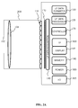
- Figure 2A is a block diagram of a light field camera device in accordance with an embodiment of the invention.
- the light field camera comprises an aperture/shutter 102, a main (objective) lens 101, a micro lens array 110 and a photosensor array 120 in accordance with the light field camera of Figure 1A .
- the light field camera includes a shutter release that is activated to capture a light-field image of a subject or scene. It will be appreciated that the functional features may also be applied to the light field camera of Figure 1B .
- the photosensor array 120 provides light field image data which is acquired by LF Data acquisition module 140 for generation of a light field data format by light field data formatting module 150 and/or for processing by light field data processor 155.
- Light field data may be stored, after acquisition and after processing, in memory 190 in a raw data format, as sub aperture images or focal stacks, or in a light field data format in accordance with embodiments of the invention.
- the light field data formatting module 150 and the light field data processor 155 are disposed in or integrated into the light field camera 100.
- the light field data formatting module 150 and/or the light field data processor 155 may be provided in a separate component external to the light field capture camera. The separate component may be local or remote with respect to the light field image capture device.
- any suitable wired or wireless protocol may be used for transmitting light field image data to the formatting module 150 or light field data processor 155; for example the light field data processor may transfer captured light field image data and/ or other data via the Internet, a cellular data network, a WiFi network, a BlueTooth communication protocol, and/ or any other suitable means.
- the light field data formatting module 150 is configured to generate data representative of the acquired light field, in accordance with embodiments of the invention.
- the light field data formatting module 150 may be implemented in software, hardware or a combination thereof.
- the light field data processor 155 is configured to operate on raw light field image data received directly from the LF data acquisition module 140 for example to generate focal stacks or a matrix of views in accordance with embodiments of the invention. Output data, such as, for example, still images, 2D video streams, and the like of the captured scene may be generated.
- the light field data processor may be implemented in software, hardware or a combination thereof.
- the light field camera 100 may also include a user interface 160 for enabling a user to provide user input to control operation of camera 100 by controller 170.
- Control of the camera may include one or more of control of optical parameters of the camera such as shutter speed, or in the case of an adjustable light field camera, control of the relative distance between the microlens array and the photosensor, or the relative distance between the objective lens and the microlens array. In some embodiments the relative distances between optical elements of the light field camera may be manually adjusted. Control of the camera may also include control of other light field data acquisition parameters, light field data formatting parameters or light field processing parameters of the camera.
- the user interface 160 may comprise any suitable user input device(s) such as a touchscreen, buttons, keyboard, pointing device, and/ or the like. In this way, input received by the user interface can be used to control and/ or configure the LF data formatting module 150 for controlling the data formatting, the LF data processor 155 for controlling the processing of the acquired light field data and controller 170 for controlling the light field camera 100.
- the light field camera includes a power source 180, such as one or more replaceable or rechargeable batteries.
- the light field camera comprises memory 190 for storing captured light-field data and/or rendered final images or other data such as software for implementing methods of embodiments of the invention.
- the memory can include external and/ or internal memory. In at least one embodiment, the memory can be provided at a separate device and/ or location from camera 100. In one embodiment, the memory includes a removable/swappable storage device such as a memory stick.
- the light field camera may also include a display unit 165 (e.g., an LCD screen) for viewing scenes in front of the camera prior to capture and/or for viewing previously captured and/or rendered images.
- the screen 165 may also be used to display one or more menus or other information to the user.
- the light field camera may further include one or more I/O interfaces 195, such as FireWire or Universal Serial Bus (USB) interfaces, or wired or wireless communication interfaces for data communication via the Internet, a cellular data network, a WiFi network, a BlueTooth communication protocol, and/ or any other suitable means.
- I/O interfaces 195 such as FireWire or Universal Serial Bus (USB) interfaces, or wired or wireless communication interfaces for data communication via the Internet, a cellular data network, a WiFi network, a BlueTooth communication protocol, and/ or any other suitable means.
- the I/O interface 195 may be used for transferring data, such as light field representative data generated by LF data formatting module in accordance with embodiments of the invention and light field data such as raw light field data or data processed by LF data processor 155, to and from external devices such as computer systems or display units, for rendering applications.
- data such as light field representative data generated by LF data formatting module in accordance with embodiments of the invention and light field data such as raw light field data or data processed by LF data processor 155, to and from external devices such as computer systems or display units, for rendering applications.
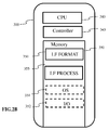
- Figure 2B is a block diagram illustrating a particular embodiment of a potential implementation of light field data formatting module 150 and the light field data processor 153.
- the circuit 300 includes memory 390, a memory controller 345 and processing circuitry 340 comprising one or more processing units (CPU(s)).
- the one or more processing units 340 are configured to run various software programs and/or sets of instructions stored in the memory 390 to perform various functions including light field data formatting and light field data processing.
- Software components stored in the memory include a data formatting module (or set of instructions) 350 for generating data representative of acquired light data in accordance with embodiments of the invention and a light field data processing module (or set of instructions) 355 for processing light field data in accordance with embodiments of the invention.
- Other modules may be included in the memory for applications of the light field camera device such as an operating system module 351 for controlling general system tasks (e.g. power management, memory management) and for facilitating communication between the various hardware and software components of the device 300, and an interface module 352 for controlling and managing communication with other devices via I/O interface ports.
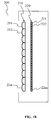
- FIG 3 illustrates an example of a 2D image formed on the photosensor array 120 of Figure 1A or the photosensor array 220 of Figure 1B .
- the 2D image often referred to as a raw 4D light field image, is composed of an array of micro images MI, each micro image being produced by the respective micro lens ( i,j ) of the microlens array 110,210.
- the micro images are arranged in the array in a rectangular lattice structure defined by axes i and j.
- a micro lens image may be referenced by the respective micro lens coordinates ( i , j ).
- a pixel PI of the photosensor 120, 220 may be referenced by its spatial coordinates ( x,y ) .
- 4D light field data associated with a given pixel may be referenced as ( x , y , i , j ) where x and y are referenced for each micro lens; For example for a micro lens having co-ordinates ( i,j ) and 20x20 pixels 0 ⁇ x ⁇ 19 and 0 ⁇ y ⁇ 19.
- a 4D light-field image can be represented, by a collection of micro-lens images as previously described with reference to Figure 3 .
- a 4D light-field image may also be represented, when recorded by a plenoptic camera by a set of sub-aperture images. Each sub-aperture image of composed of pixels of the same position selected from each microlens image.
- a 4D light-field image may be represented by a set of epipolar images.
- Embodiments of the invention provide representation of light field data based on the intersection of rays from a light field scene through a plurality of given geometrical planes. In this way the diversity in formats and light field devices may be taken into account.
- a method for parametrizing the four dimensions of lightfield radiance may be with reference to the cube illustrated in Figure 4A . All six faces of the cube may be used to parameterize the light-field. In order to parameterise direction, a second set of planes parallel to the cube faces, may be added. In this way the light field may be defined with respect to six pairs of planes with normals along the axis directions as: i ⁇ , - i ⁇ , j ⁇ , - j ⁇ , k ⁇ , - k ⁇
- Figure 4B illustrates a light field ray passing through two reference planes P1 and P2 used for parameterisation positioned parallel to one another and located at known depths z 1 and z 2 respectively.
- the light field ray intersects the first reference plane P 1 at depth z 1 at intersection point ( x 1 , y 1 ) and intersects the second reference plane P 2 at depth z 2 at intersection point ( x 2 , y 2 ).
- the light field ray may be identified by four coordinates ( x 1 , y 1 , x 2 , y 2 ).
- the light field can thus be parameterized by a pair of reference planes for parameterization P 1 , P 2 also referred herein as parametrization planes, with each light field ray being represented as a point ( x 1 , y 1 , x 2 , x 2 ,) ⁇ R 4 in 4D ray space.
- an origin of the reference co-ordinate system may be placed at the center of a plane P 1 generated by the basis vectors of the coordinate axis system ( i 1 , j 1 ).
- the entire light-field may be characterized by six pairs of such planes.
- a pair of planes, often referred to as a light slab characterizes the light-field interacting with the sensor or sensor array of the light field camera along a direction of propagation.
- n the normal
- d an offset from the origin of the 3D coordinate system along the direction of the normal.
- x 1 ⁇ x i ⁇ + u ⁇ n ⁇ x 0 ⁇ - x i ⁇ u ⁇ n ⁇
- Both sets of equation should deliver the same point x 3 as the rendered light field ray at the new location.
- Co-ordinates with a subscript 3 relate to a known point (x 3 , y 3 , z 3 ) where the light field is rendered. All depth co-ordinates z i are known.
- the parameterisation planes are in the direction of propagation or rendering.
- the light field data parameters L are (x 1 , y 1 , x 2 , y 2 )
- the light field rays that form an image at point (x 3 , y 3 , z 3 ) are linked by expression (B) which defines a hyper plane in .
- FIG. 6 shows examples of two different representations of such 2D slices restricted to the x 1 and x 2 axes.
- the left hand side, of Figure 6 illustrates respective 2D slices for different arrangements of light field rays.
- the light-field data for each set of rays is graphically illustrated in a 2D ray coordinate system or 2D ray diagram, also referred to as a phase-space system.
- Each point corresponds to a light ray and is defined by its x intersection point x 1 with the first reference plane P 1 and its x intersection point x 2 with the second reference plane P 2 .
- Figure 6A shows a collimated set of rays
- Figure 5B shows a divergent ray fan
- Figure 5C shows a convergent set of rays
- Figure 5D depicts a focused ray fan.
- the 2D ray line representation remains linear but the steepness of the lines increases with the amount of divergence.
- the rays would be plotted along the vertical axis x 2 on the 2D ray diagram.
- the 2D ray diagram of Figure 6C graphically represents a convergent set of rays. As the point of convergence is pulled toward the x 2 axis, the rays map to lines of decreasing gradient.
- the ray diagram of Figure 6D is the limit when the convergence point is on x 2 , a focused set of rays, then all rays on the diagram are located on the horizontal axis.
- a ray diagram may be used as basic representation of a light field captured by one or more light field cameras with certain portions of the light field data being generated from the raw captured format, in particular a 4D ray diagram.
- Figure 7A is a flow chart illustrating the steps of a method for generating data representative of a light field according to one or more embodiments of the invention.
- Figure 7B is a block diagram schematically illustrating the main modules of a system for generating data representative of a light field according to one or more embodiments of the invention.
- raw light field data is acquired by a light field camera 701.
- the raw light field data may for example be in the form of micro images as described with reference to Figure 3 .
- the light field camera may be a light field camera device such as shown in Figures 1A or 1B and 2A and 2B .
- step S702 the acquired light field data is processed by ray parameter module 702 to provide intersection data ( x 1 , y 1 , x 2, y 2 ) defining intersection of captured light field rays with a pair of reference planes for parameterization P 1 , P 2 at respective depths z 1 , z 2 .
- the center of projection (x 3 , y 3, z 3 ) the orientation of the optical axis of the camera and the distance f from the pinhole of the camera to the plane of the photosensor.
- the light field camera parameters are illustrated in Figure 8 .
- the photosensor plane is located at depth z p .
- the pixel output of the photosensor is converted into geometrical representation of light field rays.
- a light-slab comprising the two reference planes P 1 and P 2 is located at depths z 1 and z 2 , respectively, beyond z 3 , at the other side of the centre of projection of the camera to the photosensor.
- the above calculation may be extended to multiple cameras with different pairs of triplets ( x p , y p , z p ) ( x 3 , y 3 , z 3 ):
- intersection data (x 1 , y 1 , x 2, y 2 ) geometrically defining intersection of light field rays with reference planes P 1 , P 2 is obtained.
- step S703 ray a diagram graphically representing the intersection data (x 1 , y 1 , x 2 , y 2 ) is obtained by ray diagram generator module 703.
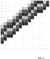
- the data lines of the ray diagram used to parameterise are sampled by 256 cells providing an image of 256x256 pixels.
- the ray diagram illustrated in Figure 9 is interpreted as a matrix of 256x256 elements, it can be seen that it is sparsely populated. If the rays were to be saved individually in a file instead of the 4D phase space matrix, this would require saving for each ray, at least 2 bytes (int16) for each position x i or x 3 plus 3 bytes for the color, i.e. 7 bytes per ray for a 2D slice light-field, and 11 bytes per ray for its full 4D representation. Even then, the rays would be stored randomly in the file which might be unsuitable for applications that need to manipulate the representation.
- the inventors of the present invention have determined how to extract only the representative data from the ray diagram matrix and to store the data in a file in a structured manner.
- the light field rays are mapped along data lines of the 2D ray diagram, it is more efficient to store parameters defining the data line rather than the line values themselves.
- Parameters defining the data line such as, for example, a slope defining parameter s and an axis intercept d may be stored with the set of light field rays belonging to that data line.
- the rays may be ordered along lines in the file. In order to set lines through matrix cells so called digital lines are generated which approximate the ray lines with minimum error.
- a Radon transform is performed by line detection module 704 on the ray diagram generated in step S703.
- a representative digital line is generated by digital line generation module 705 in step S705.
- digital lines are generated by approximating an analytical line to its nearest grid point, for example by applying Bresenham's algorithm.
- Bresenham's algorithm provides a way to provide a digital line with minimal operation.
- Other methods may apply a fast discrete Radon transform calculation.
- An example of Bresenham application is one adapted from the following reference: http://www.cs.helsinki.fi/group/goa/mallinnus/lines/bresenh.html.
- Figure 10 illustrates an example of a digital line generated by application of Bresenham's algorithm.
- Figure 11 illustrates a group of digital lines having the same slope a (or s - d ) but different intercepts d , the group of data lines being contiguous.
- the group of data lines is referred to herein as a bundle of lines and corresponds to a beam resulting from the camera not being ideally pinpoint.
- Each line addresses different pixels. In other words, one pixel belongs only to a unique line of a bundle with the same slope but different intercepts.
- the upper and lower boundaries of the axis interceptions d are given as d max and d min respectively.
- the header of the beam can simply contain the slope a and the thickness of the beam defined by the upper and lower boundaries of the axis interceptions d max - d min .
- the ray values will be stored as RGB colors along digital lines whose header can be d and s . Void cells of the ray diagram in the sampled space do not need to be stored. Coordinates x 1 ; x 2 of the rays can be deduced from the parameters d, s and from the position of the cell along the digital line.
- Parameters to be estimated from the lightfield or from camera's geometry are the slope a the lower and upper bounds of the digital line intercepts ( d min ,d max ) , and the digital line parameters ( d i ,s i ).
- the discrete Radon transform has already been discussed as a tool to measure the support location of the light-field in the ray diagram.
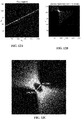
- Figure 12B shows the discrete Radon transform in the digital line parameter space ( d , s ) of the datalines of Figure 12A.
- Figure 12C is a zoom of the region of interest comprised in Figure 12B .
- the beam of digital lines is located by the search for the maximum value parameters. There could be some offset between the geometrical center of symmetry of the DRT and the actual position of the maximum due to image content so that later on, an algorithm is used to pin-point the center of symmetry instead of the maximum. Then, the waist of the beam transform as shown on Figure 12C is easy to find to give the values ( d min ,d max ) .
- the values of m and d max x , d min x , d max y , d min y may be evaluated in the discrete Radon domain.
- d max x , d min x , d max y , d min y may be evaluated in the discrete Radon domain.
- the sets of the equations may be solved for k, x 3 and y 3 .
- ( x 3 , y 3 , z 3 ) correspond to the coordinates of the camera, or in other words the voxel where the corresponding bundle of light is focused into a circle of the radius A .
- the digital lines may be scanned as before on ⁇ (x 1, x 2 ) using the Bresenham digital lines; For each individual (x 1 ,x 2 ) value, the corresponding (y 1 ,y 2 ) values captured in the light field are stored. To find such values, expression (C) is exploited. All the following are either known or estimated from expressions (F) and (G) x 3 ; y 3 ; z 3 ; z 1 ; z 2
- y 3 * varies between y 3 - A to y 3 + A.
- Table 1 An exemplary data format for a bundle of data lines per camera is illustrated in Table 1.
- the parameters ( m , k ) are found for all the peaks in the radon transform of ⁇ (x 1 ,x 2 ), and put in one set. The same is done for the peaks in ( y 1 , y 2 ) and the parameters are put in another set.
- the maximum peak intensity is found in the 2D radon transform of ( x 1 , x 2 ) and the corresponding peak in ( y 1 , y 2 ) is found by matching the previously found parameters ( m, k ). After saving the data as mentioned in the last section, these peaks are cleaned from the radon transforms, and the next iteration is started, until nothing meaningful remains in the light field
- Figure 7C illustrates a device for rendering at least one image from light field data comprising a processor 711 for processing data obtained in accordance with the method of any embodiment of the invention as hereinbefore described; and a display for rendering an image in accordance with the processed data
Landscapes
- Physics & Mathematics (AREA)
- General Physics & Mathematics (AREA)
- Engineering & Computer Science (AREA)
- Theoretical Computer Science (AREA)
- Studio Devices (AREA)
Priority Applications (11)
| Application Number | Priority Date | Filing Date | Title |
|---|---|---|---|
| EP15306434.0A EP3144884A1 (fr) | 2015-09-17 | 2015-09-17 | Représentation de données de champ lumineux |
| EP16769961.0A EP3350769A1 (fr) | 2015-09-17 | 2016-09-16 | Représentation de données de champ lumineux |
| CA2998670A CA2998670A1 (fr) | 2015-09-17 | 2016-09-16 | Representation de donnees de champ lumineux |
| US15/761,095 US10887576B2 (en) | 2015-09-17 | 2016-09-16 | Light field data representation |
| KR1020187007697A KR102635003B1 (ko) | 2015-09-17 | 2016-09-16 | 라이트 필드 데이터 표현 |
| RU2018113713A RU2018113713A (ru) | 2015-09-17 | 2016-09-16 | Представление данных светового поля |
| BR112018005399A BR112018005399A2 (pt) | 2015-09-17 | 2016-09-16 | representação de dados de campo de luz |
| CN201680067390.1A CN108292431B (zh) | 2015-09-17 | 2016-09-16 | 光场数据表示 |
| MX2018003269A MX2018003269A (es) | 2015-09-17 | 2016-09-16 | Representacion de datos de campo de luz. |
| PCT/EP2016/072043 WO2017046372A1 (fr) | 2015-09-17 | 2016-09-16 | Représentation de données de champ lumineux |
| JP2018514259A JP6878415B2 (ja) | 2015-09-17 | 2016-09-16 | ライトフィールド・データ表現 |
Applications Claiming Priority (1)
| Application Number | Priority Date | Filing Date | Title |
|---|---|---|---|
| EP15306434.0A EP3144884A1 (fr) | 2015-09-17 | 2015-09-17 | Représentation de données de champ lumineux |
Publications (1)
| Publication Number | Publication Date |
|---|---|
| EP3144884A1 true EP3144884A1 (fr) | 2017-03-22 |
Family
ID=54293190
Family Applications (1)
| Application Number | Title | Priority Date | Filing Date |
|---|---|---|---|
| EP15306434.0A Withdrawn EP3144884A1 (fr) | 2015-09-17 | 2015-09-17 | Représentation de données de champ lumineux |
Country Status (1)
| Country | Link |
|---|---|
| EP (1) | EP3144884A1 (fr) |
Citations (2)
| Publication number | Priority date | Publication date | Assignee | Title |
|---|---|---|---|---|
| US20140328535A1 (en) * | 2013-05-06 | 2014-11-06 | Disney Enterprises, Inc. | Sparse light field representation |
| US20150177062A1 (en) * | 2013-12-19 | 2015-06-25 | Canon Kabushiki Kaisha | Information processing apparatus, information processing method, and storage medium |
-
2015
- 2015-09-17 EP EP15306434.0A patent/EP3144884A1/fr not_active Withdrawn
Patent Citations (2)
| Publication number | Priority date | Publication date | Assignee | Title |
|---|---|---|---|---|
| US20140328535A1 (en) * | 2013-05-06 | 2014-11-06 | Disney Enterprises, Inc. | Sparse light field representation |
| US20150177062A1 (en) * | 2013-12-19 | 2015-06-25 | Canon Kabushiki Kaisha | Information processing apparatus, information processing method, and storage medium |
Non-Patent Citations (3)
| Title |
|---|
| TODOR GEORGIEV ET AL: "Lytro camera technology: theory, algorithms, performance analysis", PROCEEDINGS OF SPIE, vol. 8667, 26 February 2013 (2013-02-26), pages 86671J, XP055203972, ISSN: 0277-786X, DOI: 10.1117/12.2013581 * |
| TODOR GEORGIEV ET AL: "The radon image as plenoptic function", 2014 IEEE INTERNATIONAL CONFERENCE ON IMAGE PROCESSING (ICIP), 27 October 2014 (2014-10-27), pages 1922 - 1926, XP055205391, ISBN: 978-1-47-995751-4, DOI: 10.1109/ICIP.2014.7025385 * |
| YAMASHITA K ET AL: "Compressive acquisition of ray-space using radon transform", PROCEEDINGS OF THE SPIE - THE INTERNATIONAL SOCIETY FOR OPTICAL ENGINEERING SPIE - THE INTERNATIONAL SOCIETY FOR OPTICAL ENGINEERING USA, vol. 7237, 11 January 2009 (2009-01-11), XP040493754, ISSN: 0277-786X * |
Similar Documents
| Publication | Publication Date | Title |
|---|---|---|
| US10887576B2 (en) | Light field data representation | |
| US10021340B2 (en) | Method and an apparatus for generating data representative of a light field | |
| EP3065394A1 (fr) | Métadonnées de champ lumineux | |
| CN104050662A (zh) | 一种用光场相机一次成像直接获取深度图的方法 | |
| EP3398161B1 (fr) | Procédé et appareil permettant de générer des données représentatives d'un faisceau de pixels | |
| US20210329217A1 (en) | Method and an apparatus for generating data representative of a pixel beam | |
| EP3065395A1 (fr) | Traitement de données de champ lumineux | |
| US11882259B2 (en) | Light field data representation | |
| US10909704B2 (en) | Apparatus and a method for generating data representing a pixel beam | |
| EP3023826A1 (fr) | Dispositif d'imagerie à champ lumineux | |
| EP3657786A1 (fr) | Reconstruction de champ lumineux | |
| US20190101765A1 (en) | A method and an apparatus for generating data representative of a pixel beam | |
| EP3144884A1 (fr) | Représentation de données de champ lumineux |
Legal Events
| Date | Code | Title | Description |
|---|---|---|---|
| PUAI | Public reference made under article 153(3) epc to a published international application that has entered the european phase |
Free format text: ORIGINAL CODE: 0009012 |
|
| AK | Designated contracting states |
Kind code of ref document: A1 Designated state(s): AL AT BE BG CH CY CZ DE DK EE ES FI FR GB GR HR HU IE IS IT LI LT LU LV MC MK MT NL NO PL PT RO RS SE SI SK SM TR |
|
| AX | Request for extension of the european patent |
Extension state: BA ME |
|
| STAA | Information on the status of an ep patent application or granted ep patent |
Free format text: STATUS: THE APPLICATION IS DEEMED TO BE WITHDRAWN |
|
| 18D | Application deemed to be withdrawn |
Effective date: 20170923 |