EP3144879A1 - Procédé et appareil permettant de générer des données représentatives d'un champ lumineux - Google Patents
Procédé et appareil permettant de générer des données représentatives d'un champ lumineux Download PDFInfo
- Publication number
- EP3144879A1 EP3144879A1 EP15306446.4A EP15306446A EP3144879A1 EP 3144879 A1 EP3144879 A1 EP 3144879A1 EP 15306446 A EP15306446 A EP 15306446A EP 3144879 A1 EP3144879 A1 EP 3144879A1
- Authority
- EP
- European Patent Office
- Prior art keywords
- data
- light
- ray
- pixel
- light field
- Prior art date
- Legal status (The legal status is an assumption and is not a legal conclusion. Google has not performed a legal analysis and makes no representation as to the accuracy of the status listed.)
- Withdrawn
Links
- 238000000034 method Methods 0.000 title claims description 24
- 230000003287 optical effect Effects 0.000 claims abstract description 50
- 238000010586 diagram Methods 0.000 claims description 50
- 210000001747 pupil Anatomy 0.000 claims description 24
- 229910052704 radon Inorganic materials 0.000 claims description 11
- SYUHGPGVQRZVTB-UHFFFAOYSA-N radon atom Chemical compound [Rn] SYUHGPGVQRZVTB-UHFFFAOYSA-N 0.000 claims description 11
- 239000011159 matrix material Substances 0.000 claims description 10
- 238000004422 calculation algorithm Methods 0.000 claims description 8
- 238000009877 rendering Methods 0.000 claims description 5
- 239000003086 colorant Substances 0.000 claims description 3
- 238000004590 computer program Methods 0.000 claims description 3
- 238000003384 imaging method Methods 0.000 claims description 2
- 238000012545 processing Methods 0.000 abstract description 13
- 238000003491 array Methods 0.000 abstract description 2
- 230000005540 biological transmission Effects 0.000 abstract description 2
- 230000014509 gene expression Effects 0.000 description 12
- 238000004891 communication Methods 0.000 description 6
- 238000005070 sampling Methods 0.000 description 5
- 230000006870 function Effects 0.000 description 3
- PCTMTFRHKVHKIS-BMFZQQSSSA-N (1s,3r,4e,6e,8e,10e,12e,14e,16e,18s,19r,20r,21s,25r,27r,30r,31r,33s,35r,37s,38r)-3-[(2r,3s,4s,5s,6r)-4-amino-3,5-dihydroxy-6-methyloxan-2-yl]oxy-19,25,27,30,31,33,35,37-octahydroxy-18,20,21-trimethyl-23-oxo-22,39-dioxabicyclo[33.3.1]nonatriaconta-4,6,8,10 Chemical compound C1C=C2C[C@@H](OS(O)(=O)=O)CC[C@]2(C)[C@@H]2[C@@H]1[C@@H]1CC[C@H]([C@H](C)CCCC(C)C)[C@@]1(C)CC2.O[C@H]1[C@@H](N)[C@H](O)[C@@H](C)O[C@H]1O[C@H]1/C=C/C=C/C=C/C=C/C=C/C=C/C=C/[C@H](C)[C@@H](O)[C@@H](C)[C@H](C)OC(=O)C[C@H](O)C[C@H](O)CC[C@@H](O)[C@H](O)C[C@H](O)C[C@](O)(C[C@H](O)[C@H]2C(O)=O)O[C@H]2C1 PCTMTFRHKVHKIS-BMFZQQSSSA-N 0.000 description 2
- 238000004364 calculation method Methods 0.000 description 2
- 230000001413 cellular effect Effects 0.000 description 2
- 210000000887 face Anatomy 0.000 description 2
- 238000012986 modification Methods 0.000 description 2
- 230000004048 modification Effects 0.000 description 2
- 230000008569 process Effects 0.000 description 2
- 239000013598 vector Substances 0.000 description 2
- 238000010207 Bayesian analysis Methods 0.000 description 1
- 230000009471 action Effects 0.000 description 1
- 230000008859 change Effects 0.000 description 1
- 238000006243 chemical reaction Methods 0.000 description 1
- 239000012141 concentrate Substances 0.000 description 1
- 238000013461 design Methods 0.000 description 1
- 238000001514 detection method Methods 0.000 description 1
- 230000000694 effects Effects 0.000 description 1
- 238000009472 formulation Methods 0.000 description 1
- 238000005259 measurement Methods 0.000 description 1
- 239000000203 mixture Substances 0.000 description 1
- 238000012805 post-processing Methods 0.000 description 1
- 238000007781 pre-processing Methods 0.000 description 1
- 238000004321 preservation Methods 0.000 description 1
- 230000001902 propagating effect Effects 0.000 description 1
- 238000011160 research Methods 0.000 description 1
- 230000035945 sensitivity Effects 0.000 description 1
- 239000007787 solid Substances 0.000 description 1
- 238000010408 sweeping Methods 0.000 description 1
- 230000009897 systematic effect Effects 0.000 description 1
- 238000012546 transfer Methods 0.000 description 1
- 230000001052 transient effect Effects 0.000 description 1
- 239000011800 void material Substances 0.000 description 1
Images


Classifications
-
- H—ELECTRICITY
- H04—ELECTRIC COMMUNICATION TECHNIQUE
- H04N—PICTORIAL COMMUNICATION, e.g. TELEVISION
- H04N13/00—Stereoscopic video systems; Multi-view video systems; Details thereof
- H04N13/20—Image signal generators
- H04N13/204—Image signal generators using stereoscopic image cameras
- H04N13/207—Image signal generators using stereoscopic image cameras using a single 2D image sensor
- H04N13/229—Image signal generators using stereoscopic image cameras using a single 2D image sensor using lenticular lenses, e.g. arrangements of cylindrical lenses
-
- G—PHYSICS
- G02—OPTICS
- G02B—OPTICAL ELEMENTS, SYSTEMS OR APPARATUS
- G02B27/00—Optical systems or apparatus not provided for by any of the groups G02B1/00 - G02B26/00, G02B30/00
- G02B27/0075—Optical systems or apparatus not provided for by any of the groups G02B1/00 - G02B26/00, G02B30/00 with means for altering, e.g. increasing, the depth of field or depth of focus
-
- H—ELECTRICITY
- H04—ELECTRIC COMMUNICATION TECHNIQUE
- H04N—PICTORIAL COMMUNICATION, e.g. TELEVISION
- H04N23/00—Cameras or camera modules comprising electronic image sensors; Control thereof
- H04N23/50—Constructional details
-
- H—ELECTRICITY
- H04—ELECTRIC COMMUNICATION TECHNIQUE
- H04N—PICTORIAL COMMUNICATION, e.g. TELEVISION
- H04N5/00—Details of television systems
- H04N5/76—Television signal recording
- H04N5/91—Television signal processing therefor
- H04N5/92—Transformation of the television signal for recording, e.g. modulation, frequency changing; Inverse transformation for playback
- H04N5/9201—Transformation of the television signal for recording, e.g. modulation, frequency changing; Inverse transformation for playback involving the multiplexing of an additional signal and the video signal
-
- G—PHYSICS
- G02—OPTICS
- G02B—OPTICAL ELEMENTS, SYSTEMS OR APPARATUS
- G02B7/00—Mountings, adjusting means, or light-tight connections, for optical elements
- G02B7/28—Systems for automatic generation of focusing signals
- G02B7/34—Systems for automatic generation of focusing signals using different areas in a pupil plane
-
- G—PHYSICS
- G06—COMPUTING; CALCULATING OR COUNTING
- G06T—IMAGE DATA PROCESSING OR GENERATION, IN GENERAL
- G06T1/00—General purpose image data processing
- G06T1/0007—Image acquisition
-
- G—PHYSICS
- G06—COMPUTING; CALCULATING OR COUNTING
- G06T—IMAGE DATA PROCESSING OR GENERATION, IN GENERAL
- G06T5/00—Image enhancement or restoration
- G06T5/50—Image enhancement or restoration using two or more images, e.g. averaging or subtraction
-
- H—ELECTRICITY
- H04—ELECTRIC COMMUNICATION TECHNIQUE
- H04N—PICTORIAL COMMUNICATION, e.g. TELEVISION
- H04N13/00—Stereoscopic video systems; Multi-view video systems; Details thereof
- H04N13/10—Processing, recording or transmission of stereoscopic or multi-view image signals
- H04N13/194—Transmission of image signals
-
- H—ELECTRICITY
- H04—ELECTRIC COMMUNICATION TECHNIQUE
- H04N—PICTORIAL COMMUNICATION, e.g. TELEVISION
- H04N13/00—Stereoscopic video systems; Multi-view video systems; Details thereof
- H04N13/20—Image signal generators
- H04N13/204—Image signal generators using stereoscopic image cameras
-
- H—ELECTRICITY
- H04—ELECTRIC COMMUNICATION TECHNIQUE
- H04N—PICTORIAL COMMUNICATION, e.g. TELEVISION
- H04N23/00—Cameras or camera modules comprising electronic image sensors; Control thereof
- H04N23/60—Control of cameras or camera modules
-
- H—ELECTRICITY
- H04—ELECTRIC COMMUNICATION TECHNIQUE
- H04N—PICTORIAL COMMUNICATION, e.g. TELEVISION
- H04N25/00—Circuitry of solid-state image sensors [SSIS]; Control thereof
- H04N25/70—SSIS architectures; Circuits associated therewith
- H04N25/71—Charge-coupled device [CCD] sensors; Charge-transfer registers specially adapted for CCD sensors
- H04N25/75—Circuitry for providing, modifying or processing image signals from the pixel array
-
- G—PHYSICS
- G06—COMPUTING; CALCULATING OR COUNTING
- G06T—IMAGE DATA PROCESSING OR GENERATION, IN GENERAL
- G06T2200/00—Indexing scheme for image data processing or generation, in general
- G06T2200/21—Indexing scheme for image data processing or generation, in general involving computational photography
-
- G—PHYSICS
- G06—COMPUTING; CALCULATING OR COUNTING
- G06T—IMAGE DATA PROCESSING OR GENERATION, IN GENERAL
- G06T2207/00—Indexing scheme for image analysis or image enhancement
- G06T2207/10—Image acquisition modality
- G06T2207/10052—Images from lightfield camera
-
- G—PHYSICS
- G06—COMPUTING; CALCULATING OR COUNTING
- G06T—IMAGE DATA PROCESSING OR GENERATION, IN GENERAL
- G06T2207/00—Indexing scheme for image analysis or image enhancement
- G06T2207/20—Special algorithmic details
- G06T2207/20048—Transform domain processing
- G06T2207/20061—Hough transform
-
- H—ELECTRICITY
- H04—ELECTRIC COMMUNICATION TECHNIQUE
- H04N—PICTORIAL COMMUNICATION, e.g. TELEVISION
- H04N23/00—Cameras or camera modules comprising electronic image sensors; Control thereof
- H04N23/10—Cameras or camera modules comprising electronic image sensors; Control thereof for generating image signals from different wavelengths
Definitions
- the present invention relates to generation of data representing a light field.
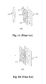
- 4D light-tield data Compared to classical two-dimensional or 2D images obtained from a camera, 4D light-tield data enable a user to have access to more post-processing features that enhance the rendering of images and the interactivity with the user. For example, with 4D light-field data, it is possible to perform refocusing of images with freely selected distances of focalization meaning that the position of a focal plane can be specified/selected a posteriori, as well as changing slightly the point of view in the scene of an image. In order to acquire 4D light-field data, several techniques can be used. For example, a plenoptic camera is able to acquire 4D light-tield data. Details of the architecture of a plenoptic camera are provided in Figure 1A.
- Figure 1A is a diagram schematically representing a plenoptic camera 100.
- the plenoptic camera 100 comprises a main lens 101, a microlens array 102 comprising a plurality of micro-lenses 103 arranged in a two-dimensional array and an image sensor 104.
- FIG. 1B represents a multi-array camera 110.
- the multi-array camera 110 comprises a lens array 112 and an image sensor 114.
- the main lens 101 receives light from an object (not shown on the figure) in an object field of the main lens 101 and passes the light through an image field of the main lens 101.
- Another way of acquiring a 4D light field is to use a conventional camera that is configured to capture a sequence of 2D images of a same scene at different focal planes.
- a conventional camera that is configured to capture a sequence of 2D images of a same scene at different focal planes.
- the technique described in the document " Light ray field capture using focal plane sweeping and its optical reconstruction using 3D displays" by J.-H. Park et al., published in OPTICS EXPRESS, Vol. 22, No. 21 , in October 2014 may be used to achieve the acquisition of 4D light field data by means of a conventional camera.
- 4D light-field data can be represented, when recorded by a plenoptic camera by a collection of micro-lens images. 4D light-field data in this representation are named raw images or raw 4D light-tield data. Secondly, 4D light-field data can be represented, either when recorded by a plenoptic camera or by a camera array, by a set of sub-aperture images.
- a sub-aperture image corresponds to a captured image of a scene from a point of view, the point of view being slightly different between two sub-aperture images.
- These sub-aperture images give information about the parallax and depth of the imaged scene.
- 4D light-field data can be represented by a set of epipolar images see for example the article entitled : " Generating EPI Representation of a 4D Light Fields with a Single Lens Focused Plenoptic Camera", by S. Wanner and al., published in the conference proceedings of ISVC 2011 .
- Light-field data can take up large amounts of storage space which can make storage cumbersome and processing less efficient.
- light-tield acquisition devices are extremely heterogeneous.
- Light-field cameras are of different types for example plenoptic or camera arrays. Within each type there are many differences such as different optical arrangements, or micro-lenses of different focal lengths. Each camera has its own proprietary file format. At present here is no standard supporting the acquisition and transmission of multi-dimensional information for an exhaustive over-view of the different parameters upon which a light-field depends. As such acquired light-field data for different cameras have a diversity of formats.
- the present invention has been devised with the foregoing in mind.
- the light field ray representative of the pixel beam is a straight line passing through the centre of the pixel and the centre of the pupil and the parameters defining the pixel beam are a position and a size of a conjugate of the pixel in the object space.
- the interception data corresponding to the light field ray is graphically represented in the ray diagram as datalines and the ray diagram parameters include data representative of at least one of:
- the datalines are detected in the 2D ray diagram by applying a Radon transform.
- the graphical representation is provided as an matrix of cells to provide a digital datalinet, each digital dataline format being defined by a plurality of cells, at least one first cell representative of the interception of the line with an axis and at least one second cell from which the slope of the line may be determined.
- each digital dataline is generated by application of Bresenham's algorithm.
- the data representative of the pixel beam further comprises colour data representing the colour of the corresponding light field ray.
- the data representative of the pixel beam is provided as meta data
- the header of meta data comprising the ray diagram parameters defining the graphical representation of the intersection data in a 2D ray diagram and the body of the metadata comprising data representative of colour of the ray and the parameters defining a position and a size of a conjugate of the pixel in the object space.
- Another object of the invention is device for providing metadata for a volume in an object space of an optical acquisition system occupied by a set of rays of light that at least one pixel of a sensor of said optical acquisition system can sense through a pupil of said optical acquisition system, said volume being called a pixel beam, the device comprising a light field data acquisition module for acquiring light field data captured by a light field camera and a light field data generation module configured to :
- Another object of the invention concerns a device for rendering an image from light field data using obtained in accordance with the method of any one of claims 1 to 8.
- elements of the invention may be computer implemented. Accordingly, such elements may take the form of an entirely hardware embodiment, an entirely software embodiment (including firmware, resident software, micro-code, etc.) or an embodiment combining software and hardware aspects that may all generally be referred to herein as a "circuit", "module” or “system'. Furthermore, such elements may take the form of a computer program product embodied in any tangible medium of expression having computer usable program code embodied in the medium.
- a tangible carrier medium may comprise a storage medium such as a floppy disk, a CD-ROM, a hard disk drive, a magnetic tape device or a solid state memory device and the like.
- a transient carrier medium may include a signal such as an electrical signal, an electronic signal, an optical signal, an acoustic signal, a magnetic signal or an electromagnetic signal, e.g. a microwave or RF signal.
- aspects of the present principles can be embodied as a system, method or computer readable medium. Accordingly, aspects of the present principles can take the form of an entirely hardware embodiment, an entirely software embodiment, (including firmware, resident software, micro-code, and so forth) or an embodiment combining software and hardware aspects that can all generally be referred to herein as a "circuit", "module”, or “system”. Furthermore, aspects of the present principles can take the form of a computer readable storage medium. Any combination of one or more computer readable storage medium(a) may be utilized.
- Embodiments of the invention provide formatting of light-field data for further processing applications such as format conversion, refocusing, viewpoint change and 3D image generation.
- FIG 2A is a block diagram of a light-tield camera device in accordance with an embodiment of the invention.
- the light-field camera comprises an aperture/shutter 202, a main (objective) lens 201, a micro lens array 210 and a photosensor array 220 in accordance with the light-field camera of Figure 1A .
- the light-field camera includes a shutter release that is activated to capture a light-tield image of a subject or scene. It will be appreciated that the functional features may also be applied to the light-field camera of Figure 1B .
- the photosensor array 220 provides light-field image data which is acquired by LF Data acquisition module 240 for generation of a light-field data format by light-field data formatting module 250 and/or for processing by light-tield data processor 255.
- Light-field data may be stored, after acquisition and after processing, in memory 290 in a raw data format, as sub aperture images or focal stacks, or in a light-field data format in accordance with embodiments of the invention.
- the light-field data formatting module 150 and the light-field data processor 255 are disposed in or integrated into the light-field camera 200.
- the light-tield data formatting module 250 and/or the light-tield data processor 255 may be provided in a separate component external to the light-tield capture camera. The separate component may be local or remote with respect to the light-field image capture device.
- any suitable wired or wireless protocol may be used for transmitting light-field image data to the formatting module 250 or light-field data processor 255; for example the light-field data processor may transfer captured light-field image data and/ or other data via the Internet, a cellular data network, a WiFi network, a BlueTooth communication protocol, and/ or any other suitable means.
- the light-field data formatting module 250 is configured to generate data representative of the acquired light-field, in accordance with embodiments of the invention.
- the light-tield data formatting module 250 may be implemented in software, hardware or a combination thereof.
- the light-field data processor 255 is configured to operate on raw light-field image data received directly from the LF data acquisition module 240 for example to generate focal stacks or a matrix of views in accordance with embodiments of the invention. Output data, such as, for example, still images, 2D video streams, and the like of the captured scene may be generated.
- the light-field data processor may be implemented in software, hardware or a combination thereof.
- the light-field camera 200 may also include a user interface 260 for enabling a user to provide user input to control operation of camera 100 by controller 270.
- Control of the camera may include one or more of control of optical parameters of the camera such as shutter speed, or in the case of an adjustable light-field camera, control of the relative distance between the microlens array and the photosensor, or the relative distance between the objective lens and the microlens array. In some embodiments the relative distances between optical elements of the light-field camera may be manually adjusted. Control of the camera may also include control of other light-field data acquisition parameters, light-field data formatting parameters or light-field processing parameters of the camera.
- the user interface 260 may comprise any suitable user input device(s) such as a touchscreen, buttons, keyboard, pointing device, and/ or the like. In this way, input received by the user interface can be used to control and/ or configure the LF data formatting module 250 for controlling the data formatting, the LF data processor 255 for controlling the processing of the acquired light-field data and controller 270 for controlling the light-tield camera 200.
- the light-field camera includes a power source 280, such as one or more replaceable or rechargeable batteries.
- the light-field camera comprises memory 290 for storing captured light-tield data and/or rendered final images or other data such as software for implementing methods of embodiments of the invention.
- the memory can include external and/ or internal memory. In at least one embodiment, the memory can be provided at a separate device and/ or location from camera 200. In one embodiment, the memory includes a removable/swappable storage device such as a memory stick.
- the light-field camera may also include a display unit 265 (e.g., an LCD screen) for viewing scenes in front of the camera prior to capture and/or for viewing previously captured and/or rendered images.
- the screen 265 may also be used to display one or more menus or other information to the user.
- the light-field camera may further include one or more I/O interfaces 295, such as FireWire or Universal Serial Bus (USB) interfaces, or wired or wireless communication interfaces for data communication via the Internet, a cellular data network, a WiFi network, a BlueTooth communication protocol, and/ or any other suitable means.
- I/O interfaces 295 such as FireWire or Universal Serial Bus (USB) interfaces, or wired or wireless communication interfaces for data communication via the Internet, a cellular data network, a WiFi network, a BlueTooth communication protocol, and/ or any other suitable means.
- the I/O interface 295 may be used for transferring data, such as light-tield representative data generated by LF data formatting module in accordance with embodiments of the invention and light-field data such as raw light-tield data or data processed by LF data processor 255, to and from external devices such as computer systems or display units, for rendering applications.
- data such as light-tield representative data generated by LF data formatting module in accordance with embodiments of the invention and light-field data such as raw light-tield data or data processed by LF data processor 255, to and from external devices such as computer systems or display units, for rendering applications.
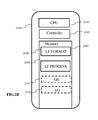
- Figure 2B is a block diagram illustrating a particular embodiment of a potential implementation of light-field data formatting module 250 and the light-field data processor 253.
- the circuit 2000 includes memory 2090, a memory controller 2045 and processing circuitry 2040 comprising one or more processing units (CPU(s)).
- the one or more processing units 2040 are configured to run various software programs and/or sets of instructions stored in the memory 2090 to perform various functions including light-field data formatting and light-field data processing.
- Software components stored in the memory include a data formatting module (or set of instructions) 2050 for generating data representative of acquired light data in accordance with embodiments of the invention and a light-field data processing module (or set of instructions) 2055 for processing light-field data in accordance with embodiments of the invention.
- Other modules may be included in the memory for applications of the light-field camera device such as an operating system module 2051 for controlling general system tasks (e.g. power management, memory management) and for facilitating communication between the various hardware and software components of the device 2000, and an interface module 2052 for controlling and managing communication with other devices via I/O interface ports.
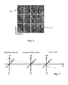
- FIG 3 illustrates an example of a 2D image formed on the photosensor array 104 of Figure 1A or the photosensor array 114 of Figure 1B .
- the 2D image often referred to as a raw 4D light-field image, is composed of an array of micro images MI, each micro image being produced by the respective micro lens ( i, j ) of the microlens array 102,112.
- the micro images are arranged in the array in a rectangular lattice structure defined by axes i and j .
- a micro lens image may be referenced by the respective micro lens coordinates ( i , j ).
- a pixel PI of the photosensor 104, 114 may be referenced by its spatial coordinates ( x, y ).
- 4D light-field data associated with a given pixel may be referenced as ( x, y , i, j ).
- a 4D light-field image can be represented, by a collection of micro-lens images as previously described with reference to Figure 3 .
- a 4D light-field image may also be represented, when recorded by a plenoptic camera by a set of sub-aperture images. Each sub-aperture image of composed of pixels of the same position selected from each microlens image.
- a 4D light-field image may be represented by a set of epipolar images, which is not the case of the pixel beam.
- Embodiments of the invention provide a representation of light-tield data based on the notion of pixel beam.
- the diversity in formats and light-field devices may be taken into account.
- one drawback of ray based formats is that the parametrization planes have to be sampled to reflect the pixel formats and sizes. Therefore, the sampling needs to be defined along other data in order to recover physical meaningful information.
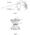
- a pixel beam 40 represents a volume occupied by a set of rays of light in an object space of an optical system 41 of a camera.
- the set of rays of light is sensed by a pixel 42 of a sensor 43 of the camera through a pupil 44 of said optical system 41
- pixel beams 40 may be sample at will since they convey per se the " étendue " which corresponds to the preservation of the energy across sections of the physical light rays.
- a pupil of an optical system is defined as the image of an aperture stop as seen through said optical system, i.e. the lenses of the camera, which precedes said aperture stop.
- An aperture stop is an opening which limits the amount of light which passes through the optical system of the camera.
- an adjustable diaphragm located near the front of a camera lens is the aperture stop for the lens.
- the amount of light admitted through the diaphragm is controlled by the diameter of the diaphragm opening which may adapted depending of the amount of light a user of the camera wishes to admit. For example, making the aperture smaller reduces the amount of light admitted through the diaphragm, but increases the depth of focus.
- the effective size of a stop may be larger or smaller than its physical size because of the refractive action of a lens.
- a pupil is the image of the aperture stop through a part of the optical system of the camera.
- a pixel beam 40 is defined as a pencil of rays of light that reach a given pixel 42 when propagating through the optical system 41 via an entrance pupil 44. As light travel on straight lines in free space, the shape of such a pixel beam 40 can be defined by two sections, one being the conjugate 45 of the pixel 42, and the other being the entrance pupil 44.
- the pixel 42 is defined by its non-null surface and its sensitivity map.
- a pixel beam may be represented by an hyperboloid of one sheet 50, as shown on figure 5 , supported by two elements : the pupil 54 and the conjugate 55 of the pixel 42 in the object space of the camera.
- a hyperboloid of one sheet is a ruled surface that can support the notion of pencil of rays of light and is compatible with the notion of " étendue " of physical light beams.
- a pixel beam 40, 50 is defined by four independent parameters: z P , ⁇ x , ⁇ y , a defining the position and size of the pixel conjugate 45, 55, in front of the pupil 44, 54.
- An origin O of a coordinate system ( x, y, z ) in which the parameters of the pixel beam 40, 50 are defined corresponds to the centre of the pupil 44 as shown on figure 4 , where the z axis defines a direction normal to the surface of the pupil 44, 54.
- the parameters ⁇ x , ⁇ y define a chief ray directions relative to the entrance of the pupil 44 centre. They depend on the pixel 42 position on the sensor 43 and on the optical elements of the optical system 41. More precisely, the parameters ⁇ x , ⁇ y represent shear angles defining a direction of the conjugate 45 of the pixel 42 from the centre of the pupil 44.
- the parameter z P represents a distance of the waist 55 of the pixel beam 40, 50, or the conjugate 45 of the pixel 42, along the z axis.
- the computation of the values of the parameters z P , a and c is realized for each pixel beam of a given camera during a calibration phase of said camera.
- This calibration phase consists, for example, in running a program capable of modelling a propagation of rays of light through the optical system of the camera.
- a program is for example an optical design program such as Zemax , ⁇ , ASAP ⁇ or Code V ⁇ .
- An optical design program is used to design and analyze optical systems.
- An optical design program models the propagation of rays of light through the optical system; and can model the effect of optical elements such as simple lenses, aspheric lenses, gradient index lenses, mirrors, and diffractive optical elements, etc.
- a pixel beam 40, 50 may be defined by its chief ray and the parameters z P , a and c.
- a method for parametrizing the four dimensions of light-field radiance may be with reference to the cube illustrated in Figure 6A . All six faces of the cube may be used to parameterize the light-field. In order to parameterize direction, a second set of planes parallel to the cube faces, may be added. In this way the light-tield may be defined with respect to six pairs of planes with normals along the axis directions as: i ⁇ , - i ⁇ , j ⁇ , - j ⁇ , k ⁇ , - k ⁇
- Figure 6B illustrates a light-field ray passing through two reference planes P1 and P2 used for parameterization positioned parallel to one another and located at known depths z 1 and z 2 respectively.
- the light-field ray intersects the first reference plane P 1 at depth z 1 at intersection point ( x 1 , y 1 ) and intersects the second reference plane P 2 at depth z 2 at intersection point ( x 2 , y 2 ).
- the light-tield ray may be identified by four coordinates ( x 1 , y 1 , x 2 , y 2 ).
- the light-field can thus be parameterized by a pair of reference planes for parameterization P 1 , P 2 also referred herein as parametrization planes, with each light-field ray being represented as a point ( x 1 , y 1 , x 2 , x 2 ,) ⁇ R 4 in 4D ray space.
- an origin of the reference co-ordinate system may be placed at the center of a plane P 1 generated by the basis vectors of the coordinate axis system ( i 1, j 1 ).
- the entire light-field may be characterized by six pairs of such planes.
- a pair of planes, often referred to as a light slab characterizes the light-field interacting with the sensor or sensor array of the light-field camera along a direction of propagation.
- x 1 ⁇ x i ⁇ + u ⁇ n ⁇ x 0 ⁇ - x i ⁇ u ⁇ n ⁇
- Both sets of equation should deliver the same point x 3 as the rendered light-field ray at the new location.
- Co-ordinates with a subscript 3 relate to a known point ( x 3 , y 3 , z 3 ) where the light-field is rendered. All depth co-ordinates z i are known.
- the parameterisation planes are in the direction of propagation or rendering.
- the light-field data parameters L are ( x 1 , y 1 , x 2 , y 2 )
- the light-tield rays that form an image at point ( x 3 , y 3 , z 3 ) are linked by expression (B) which defines a hyper plane in .
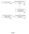
- Figure 8A is a flow chart illustrating the steps of a method for generating data representative of a light-field according to one or more embodiments of the invention.
- Figure 8B is a block diagram schematically illustrating the main modules of a system for generating data representative of a light-tield according to one or more embodiments of the invention.
- parameters defining the different pixel beams associated to the pixels of the sensor of the camera are acquired either by calibrating the camera of by retrieving such parameters from a data file stored in a remote server or on a local storage unit such as the memory 290 of the camera or a flash disk connected to the camera.
- Such parameters are the coordinates of the chief rays of the different pixel beams and the parameters z P and a defining the position and size of the pixel conjugate in front of the pupil obtained for each pixel beam during the calibration of the camera.
- a chief ray of a pixel beam is a straight line passing through the centre of the pixel and the centre of the pupil supporting the pixel beam.
- raw light-field data may for example be in the form of micro images as described with reference to Figure 3 .
- the light-field camera may be a light-tield camera device such as shown in Figures 1A or 1B and 2A and 2B .
- step S803 the acquired light-field data is processed by ray parameter module 802 to provide intersection data ( x 1 , y 1 , x 2 , y 2 ) defining intersection of captured light-tield rays, which correspond to chief rays of pixel beams 40, 50, with a pair of reference planes for parameterization P 1 , P 2 at respective depths z 1 , z 2 .
- the centre of projection ( x 3 , y 3 , z 3 ) the orientation of the optical axis of the camera and the distance f from the pinhole of the camera to the plane of the photosensor.
- the light-field camera parameters are illustrated in Figure 9 .
- the photosensor plane is located at depth z p .
- the pixel output of the photosensor is converted into geometrical representation of light-tield rays.
- a light-slab comprising the two reference planes P 1 and P 2 is located at depths z 1 and z 2 , respectively, beyond z 3 , at the other side of the centre of projection of the camera to the photosensor.
- the above calculation may be extended to multiple cameras with different pairs of triplets ( x p , y p , z p ) ( x 3 , y 3 , z 3 ):
- intersection data ( x 1 , y 1 , x 2 , y 2 ) geometrically defining intersection of light-field rays with reference planes P 1 , P 2 is obtained.
- step S804 2D ray a diagram graphically representing the intersection data ( x 1 , y 1 , x 2 , y 2 ) is obtained by ray diagram generator module 803.
- the data lines of the ray diagram used to parameterise are sampled by 256 cells providing an image of 256x256 pixels.
- the ray diagram illustrated in Figure 10 is interpreted as a matrix, it can be seen that it is sparsely populated. If the rays were to be saved individually in a file instead of the 4D phase space matrix, this would require saving for each ray, at least 2 bytes (int16) for each position x i or x 3 plus 3 bytes for the color, i.e. 7 bytes per ray for a 2D slice light-field, and 11 bytes per ray for its full 4D representation. Even then, the rays would be stored randomly in the file which might be unsuitable for applications that need to manipulate the representation.
- the inventors of the present invention have determined how to extract only the representative data from the ray diagram matrix and to store the data in a file in a structured manner.
- the 2D sliced light-field rays are mapped along data lines of the 2D ray diagram, it is more efficient to store parameters defining the data line rather than the line values themselves.
- Parameters defining the data line such as, for example, a slope defining parameter s and an axis intercept d may be stored with the set of light-field rays belonging to that data line.
- the rays may be ordered along lines in the file. In order to set lines through matrix cells so called digital lines are generated which approximate the ray lines with minimum error.
- a Radon transform is performed by line detection module 804 on the ray diagram generated in step S804.
- a representative digital line is generated by digital line generation module 805 in step S806.
- digital lines are generated by approximating an analytical line to its nearest grid point, for example by applying Bresenham's algorithm.
- Bresenham's algorithm provides a way to provide a digital line with minimal operation.
- An example of Bresenham application is one adapted from the following reference: http://www.cs.helsinhi.fi/group/goa/mallinnus/lines/bresenh.html.
- Figure 11 illustrates an example of a digital line generated by application of Bresenham's algorithm.
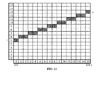
- Figure 12 illustrates a group of digital lines having the same slope a (or s - d ) but different intercepts d , the group of data lines being contiguous.
- the group of data lines is referred to herein as a bundle of lines and corresponds to a beam resulting from the camera not being ideally pinpoint.
- Each line addresses different pixels. In other words, one pixel belongs only to a unique line of a bundle with the same slope but different intercepts.
- the upper and lower boundaries of the axis interceptions d are given as d max and d min respectively.
- the header of the beam can simply contain the slope a and the thickness of the beam defined by the upper and lower boundaries of the axis interceptions d max - d min .
- the ray values will be stored as RGB colors along digital lines whose header can be d and s. Void cells of the ray diagram in the sampled space do not need to be stored. Coordinates x1; x2 of the rays can be deduced from the parameters d, s and from the position of the cell along the digital line.
- Parameters to be estimated from the lightfield or from camera's geometry are the slope a the lower and upper bounds of the digital line intercepts ( d min , d max ) ,and the digital line parameters ( d i , s i ).
- the discrete Radon transform has already been discussed as a tool to measure the support location of the light-tield in the ray diagram.
- Figure 13B shows the discrete Radon transform in the digital line parameter space ( d, s ) of the datalines of Figure 13A .
- Figure 13C is a zoom of the region of interest comprised in Figure 12B .
- the beam of digital lines is located by the search for the maximum value parameters. There could be some offset between the geometrical center of symmetry of the DRT and the actual position of the maximum due to image content so that later on, an algorithm is used to pin-point the center of symmetry instead of the maximum. Then, the waist of the beam transform as shown on Figure 13C is easy to find to give the values ( d min , d max ).
- the values of m and dm ax x , d min x , d max y , d min y may be evaluated in the discrete domain
- m and dm ax x , d min x , d max y , d min y may be evaluated in the discrete domain
- the sets of the equations may be solved tor k , x 3 and y 3 .
- ( x 3 , y 3 , z 3 ) correspond to the coordinates of the camera, or in other words the voxel where the corresponding bundle of light is focused into a circle of the radius A.
- the digital lines may be scanned as before on ⁇ (x 1 , x 2 ) using the Bresenham digital lines; For each individual (x 1 , x 2 ), value, the corresponding (y 1 , y 2 ) values captured in the light-field are stored. To find such values, expression C is exploited. All the following are either known or estimated from expressions F and G x3; y3; z3; z1; z2
- Table 1 An exemplary data format for a bundle of data lines per camera is illustrated in Table 1.
- the values of the parameters z P , a of a given pixel beam are stored alongside the RGB values of the corresponding light-field ray as shown in table 1.
- the parameters ( m , k ) are found for all the peaks in the radon transform of ⁇ (x 1 , x 2 ), and put in one set. The same is done for the peaks in ( y 1 , y 2 ) and the parameters are put in another set.
- the maximum peak intensity is found in the 2D radon transform of ( x 1 , x 2 ) and the corresponding peak in ( y 1 , y 2 ) is found by matching the previously found parameters ( m , k ). After saving the data as mentioned in the last section, these peaks are cleaned from the radon transforms, and the next iteration is started, until nothing meaningful remains in the light-field
Landscapes
- Physics & Mathematics (AREA)
- Engineering & Computer Science (AREA)
- General Physics & Mathematics (AREA)
- Multimedia (AREA)
- Signal Processing (AREA)
- Theoretical Computer Science (AREA)
- Optics & Photonics (AREA)
- Studio Devices (AREA)
- Image Processing (AREA)
- Closed-Circuit Television Systems (AREA)
- Image Analysis (AREA)
Priority Applications (11)
| Application Number | Priority Date | Filing Date | Title |
|---|---|---|---|
| EP15306446.4A EP3144879A1 (fr) | 2015-09-17 | 2015-09-17 | Procédé et appareil permettant de générer des données représentatives d'un champ lumineux |
| EP16185552.3A EP3144880B1 (fr) | 2015-09-17 | 2016-08-24 | Procédé et appareil permettant de générer des données représentatives d'un champ lumineux |
| CA2940535A CA2940535A1 (fr) | 2015-09-17 | 2016-08-29 | Une methode et un appareil de generation de donnees representatives d'un champ de lumiere |
| RU2016136352A RU2734018C2 (ru) | 2015-09-17 | 2016-09-09 | Способ и устройство для формирования данных, представляющих световое поле |
| KR1020160118178A KR102583723B1 (ko) | 2015-09-17 | 2016-09-13 | 라이트 필드를 나타내는 데이터를 생성하기 위한 방법 및 장치 |
| CN201610825429.3A CN107018293B (zh) | 2015-09-17 | 2016-09-14 | 生成表示光场的数据的方法和装置 |
| MX2016011964A MX357947B (es) | 2015-09-17 | 2016-09-14 | Un metodo y un aparato para generar datos representativos de un campo luminoso. |
| TW105129900A TW201730707A (zh) | 2015-09-17 | 2016-09-14 | 產生光場資料表示之方法及裝置 |
| JP2016180175A JP2017063414A (ja) | 2015-09-17 | 2016-09-15 | ライト・フィールドを表すデータを生成する方法および装置 |
| US15/268,480 US10021340B2 (en) | 2015-09-17 | 2016-09-16 | Method and an apparatus for generating data representative of a light field |
| JP2022095978A JP2022141637A (ja) | 2015-09-17 | 2022-06-14 | ライト・フィールドを表すデータを生成する方法および装置 |
Applications Claiming Priority (1)
| Application Number | Priority Date | Filing Date | Title |
|---|---|---|---|
| EP15306446.4A EP3144879A1 (fr) | 2015-09-17 | 2015-09-17 | Procédé et appareil permettant de générer des données représentatives d'un champ lumineux |
Publications (1)
| Publication Number | Publication Date |
|---|---|
| EP3144879A1 true EP3144879A1 (fr) | 2017-03-22 |
Family
ID=54252224
Family Applications (2)
| Application Number | Title | Priority Date | Filing Date |
|---|---|---|---|
| EP15306446.4A Withdrawn EP3144879A1 (fr) | 2015-09-17 | 2015-09-17 | Procédé et appareil permettant de générer des données représentatives d'un champ lumineux |
| EP16185552.3A Active EP3144880B1 (fr) | 2015-09-17 | 2016-08-24 | Procédé et appareil permettant de générer des données représentatives d'un champ lumineux |
Family Applications After (1)
| Application Number | Title | Priority Date | Filing Date |
|---|---|---|---|
| EP16185552.3A Active EP3144880B1 (fr) | 2015-09-17 | 2016-08-24 | Procédé et appareil permettant de générer des données représentatives d'un champ lumineux |
Country Status (9)
| Country | Link |
|---|---|
| US (1) | US10021340B2 (fr) |
| EP (2) | EP3144879A1 (fr) |
| JP (2) | JP2017063414A (fr) |
| KR (1) | KR102583723B1 (fr) |
| CN (1) | CN107018293B (fr) |
| CA (1) | CA2940535A1 (fr) |
| MX (1) | MX357947B (fr) |
| RU (1) | RU2734018C2 (fr) |
| TW (1) | TW201730707A (fr) |
Families Citing this family (12)
| Publication number | Priority date | Publication date | Assignee | Title |
|---|---|---|---|---|
| US10317597B2 (en) * | 2014-08-26 | 2019-06-11 | The Board Of Trustees Of The Leland Stanford Junior University | Light-field microscopy with phase masking |
| CA2998690A1 (fr) * | 2015-09-17 | 2017-03-23 | Thomson Licensing | Procede de codage d'un contenu de champ lumineux |
| EP3144888A1 (fr) * | 2015-09-17 | 2017-03-22 | Thomson Licensing | Appareil et procédé permettant de générer des données représentant un faisceau de pixels |
| EP3145168A1 (fr) * | 2015-09-17 | 2017-03-22 | Thomson Licensing | Appareil et procédé permettant de générer des données représentant un faisceau de pixels |
| WO2017210781A1 (fr) * | 2016-06-07 | 2017-12-14 | Airy3D Inc. | Dispositif et procédé d'imagerie à champ lumineux d'acquisition de profondeur et d'imagerie tridimensionnelle |
| CN106373152B (zh) * | 2016-09-18 | 2019-02-01 | 清华大学深圳研究生院 | 一种基于手持式光场相机的距离估计方法 |
| KR20210038892A (ko) * | 2018-08-08 | 2021-04-08 | 유니버시타트 데 발렌시아 | 플렌옵틱 오큘라 장치 |
| WO2020185414A1 (fr) * | 2019-03-08 | 2020-09-17 | Pcms Holdings, Inc. | Procédé et système optiques pour affichages basés sur des faisceaux ayant une profondeur de foyer étendue |
| RU2760845C1 (ru) * | 2021-02-12 | 2021-11-30 | Федеральное государственное бюджетное военное образовательное учреждение высшего образования "Военно-космическая академия имени А.Ф. Можайского" Министерства обороны Российской Федерации | Способ обнаружения и определения характеристик целей на основе регистрации и обработки хода лучей от объектов в наблюдаемом пространстве и устройство для его реализации |
| WO2022193104A1 (fr) * | 2021-03-15 | 2022-09-22 | 华为技术有限公司 | Procédé pour générer un modèle de prédiction de champ lumineux, et appareil associé |
| CN116070687B (zh) * | 2023-03-06 | 2023-07-04 | 浙江优众新材料科技有限公司 | 一种基于全局光线空间仿射变换的神经网络光场表示方法 |
| CN116778068B (zh) * | 2023-08-22 | 2023-11-10 | 中国电子科技集团公司第十五研究所 | 基于视点椭球相似特征数的光线采样精确优化方法 |
Citations (3)
| Publication number | Priority date | Publication date | Assignee | Title |
|---|---|---|---|---|
| EP2239706A1 (fr) * | 2008-01-15 | 2010-10-13 | Universidad De La Laguna | Procédé et chambre d'acquisition en temps réel d'informations visuelles de scènes tridimensionnelles |
| EP2806396A1 (fr) * | 2013-05-06 | 2014-11-26 | Disney Enterprises, Inc. | Représentation du champ lumineux épars |
| US20150177062A1 (en) * | 2013-12-19 | 2015-06-25 | Canon Kabushiki Kaisha | Information processing apparatus, information processing method, and storage medium |
Family Cites Families (15)
| Publication number | Priority date | Publication date | Assignee | Title |
|---|---|---|---|---|
| US6097394A (en) * | 1997-04-28 | 2000-08-01 | Board Of Trustees, Leland Stanford, Jr. University | Method and system for light field rendering |
| US6342917B1 (en) * | 1998-01-16 | 2002-01-29 | Xerox Corporation | Image recording apparatus and method using light fields to track position and orientation |
| US20120249550A1 (en) * | 2009-04-18 | 2012-10-04 | Lytro, Inc. | Selective Transmission of Image Data Based on Device Attributes |
| JP2010256291A (ja) | 2009-04-28 | 2010-11-11 | Toyota Motor Corp | 距離画像撮影装置 |
| KR101668869B1 (ko) * | 2009-05-29 | 2016-10-28 | 삼성전자주식회사 | 거리 센서, 3차원 이미지 센서 및 그 거리 산출 방법 |
| US8749694B2 (en) * | 2010-08-27 | 2014-06-10 | Adobe Systems Incorporated | Methods and apparatus for rendering focused plenoptic camera data using super-resolved demosaicing |
| IN2014CN02708A (fr) * | 2011-09-28 | 2015-08-07 | Pelican Imaging Corp | |
| JP6095266B2 (ja) * | 2012-01-13 | 2017-03-15 | キヤノン株式会社 | 画像処理装置及びその制御方法 |
| US9300932B2 (en) * | 2012-05-09 | 2016-03-29 | Lytro, Inc. | Optimization of optical systems for improved light field capture and manipulation |
| US8754829B2 (en) * | 2012-08-04 | 2014-06-17 | Paul Lapstun | Scanning light field camera and display |
| JP6159097B2 (ja) * | 2013-02-07 | 2017-07-05 | キヤノン株式会社 | 画像処理装置、撮像装置、制御方法、及びプログラム |
| KR20150127507A (ko) * | 2014-05-07 | 2015-11-17 | 엘지전자 주식회사 | 디스플레이 장치 및 디스플레이 장치의 제어 방법 |
| KR102364084B1 (ko) * | 2014-10-21 | 2022-02-17 | 엘지전자 주식회사 | 이동단말기 및 그 제어방법 |
| CN104330174B (zh) * | 2014-10-23 | 2017-05-31 | 北京理工大学 | 一种用于测量涡旋光束的周期渐变光栅及测量方法 |
| CN104598744B (zh) * | 2015-01-27 | 2017-11-21 | 北京工业大学 | 一种基于光场的深度估计方法 |
-
2015
- 2015-09-17 EP EP15306446.4A patent/EP3144879A1/fr not_active Withdrawn
-
2016
- 2016-08-24 EP EP16185552.3A patent/EP3144880B1/fr active Active
- 2016-08-29 CA CA2940535A patent/CA2940535A1/fr not_active Abandoned
- 2016-09-09 RU RU2016136352A patent/RU2734018C2/ru active
- 2016-09-13 KR KR1020160118178A patent/KR102583723B1/ko active IP Right Grant
- 2016-09-14 MX MX2016011964A patent/MX357947B/es active IP Right Grant
- 2016-09-14 CN CN201610825429.3A patent/CN107018293B/zh active Active
- 2016-09-14 TW TW105129900A patent/TW201730707A/zh unknown
- 2016-09-15 JP JP2016180175A patent/JP2017063414A/ja not_active Ceased
- 2016-09-16 US US15/268,480 patent/US10021340B2/en active Active
-
2022
- 2022-06-14 JP JP2022095978A patent/JP2022141637A/ja active Pending
Patent Citations (3)
| Publication number | Priority date | Publication date | Assignee | Title |
|---|---|---|---|---|
| EP2239706A1 (fr) * | 2008-01-15 | 2010-10-13 | Universidad De La Laguna | Procédé et chambre d'acquisition en temps réel d'informations visuelles de scènes tridimensionnelles |
| EP2806396A1 (fr) * | 2013-05-06 | 2014-11-26 | Disney Enterprises, Inc. | Représentation du champ lumineux épars |
| US20150177062A1 (en) * | 2013-12-19 | 2015-06-25 | Canon Kabushiki Kaisha | Information processing apparatus, information processing method, and storage medium |
Non-Patent Citations (6)
| Title |
|---|
| ANAT LEVIN: "Understanding camera trade-o .r through a Bayesian analysis of light fie/d projections", THE CONFERENCE PROCEEDINGS OF ECCV, 2008 |
| INDEED; REN NG: "Ph.D dissertation thesis", July 2006, article "Digital Light Field Photography''" |
| J.-H. PARK ET AL.: "Light ray-field capture using focal plane sweeping and its optical reconstruction using 3D displays", OPTICS EXPRESS, vol. 22, no. 21, October 2014 (2014-10-01) |
| S. WANNER: "Generating EPI Representation of a 4D Light Fields with a Single Lens Focused Plenoptic Camera", THE CONFERENCE PROCEEDINGS OF ISVC, 2011 |
| TODOR GEORGIEV ET AL: "Lytro camera technology: theory, algorithms, performance analysis", PROCEEDINGS OF SPIE, vol. 8667, 26 February 2013 (2013-02-26), pages 86671J, XP055203972, ISSN: 0277-786X, DOI: 10.1117/12.2013581 * |
| TODOR GEORGIEV ET AL: "The radon image as plenoptic function", 2014 IEEE INTERNATIONAL CONFERENCE ON IMAGE PROCESSING (ICIP), 27 October 2014 (2014-10-27), pages 1922 - 1926, XP055205391, ISBN: 978-1-47-995751-4, DOI: 10.1109/ICIP.2014.7025385 * |
Also Published As
| Publication number | Publication date |
|---|---|
| CN107018293B (zh) | 2020-11-03 |
| TW201730707A (zh) | 2017-09-01 |
| CN107018293A (zh) | 2017-08-04 |
| JP2022141637A (ja) | 2022-09-29 |
| KR102583723B1 (ko) | 2023-10-05 |
| RU2016136352A (ru) | 2018-03-15 |
| RU2016136352A3 (fr) | 2020-04-17 |
| JP2017063414A (ja) | 2017-03-30 |
| EP3144880B1 (fr) | 2019-08-21 |
| US20170085832A1 (en) | 2017-03-23 |
| RU2734018C2 (ru) | 2020-10-12 |
| US10021340B2 (en) | 2018-07-10 |
| MX357947B (es) | 2018-07-31 |
| KR20170035804A (ko) | 2017-03-31 |
| CA2940535A1 (fr) | 2017-03-17 |
| EP3144880A1 (fr) | 2017-03-22 |
| MX2016011964A (es) | 2017-04-25 |
Similar Documents
| Publication | Publication Date | Title |
|---|---|---|
| EP3144880B1 (fr) | Procédé et appareil permettant de générer des données représentatives d'un champ lumineux | |
| EP3144887A1 (fr) | Procédé et appareil permettant de générer des données représentatives d'un faisceau de pixels | |
| EP3398161B1 (fr) | Procédé et appareil permettant de générer des données représentatives d'un faisceau de pixels | |
| EP3350770B1 (fr) | Appareil et procédé permettant de générer des données représentant un faisceau de pixels | |
| EP3188124A1 (fr) | Procédé et appareil permettant de générer des données représentatives d'un faisceau de pixels | |
| EP3350982B1 (fr) | Appareil et procédé permettant de générer des données représentant un faisceau de pixels | |
| EP3479571B1 (fr) | Procédé et appareil permettant de générer des données représentatives d'un faisceau de pixels |
Legal Events
| Date | Code | Title | Description |
|---|---|---|---|
| PUAI | Public reference made under article 153(3) epc to a published international application that has entered the european phase |
Free format text: ORIGINAL CODE: 0009012 |
|
| AK | Designated contracting states |
Kind code of ref document: A1 Designated state(s): AL AT BE BG CH CY CZ DE DK EE ES FI FR GB GR HR HU IE IS IT LI LT LU LV MC MK MT NL NO PL PT RO RS SE SI SK SM TR |
|
| AX | Request for extension of the european patent |
Extension state: BA ME |
|
| STAA | Information on the status of an ep patent application or granted ep patent |
Free format text: STATUS: THE APPLICATION IS DEEMED TO BE WITHDRAWN |
|
| 18D | Application deemed to be withdrawn |
Effective date: 20170923 |