EP3144847B1 - Tracking spatial placement of hf rfid tag objects on a surface using multiple reception antennas - Google Patents
Tracking spatial placement of hf rfid tag objects on a surface using multiple reception antennas Download PDFInfo
- Publication number
- EP3144847B1 EP3144847B1 EP16185741.2A EP16185741A EP3144847B1 EP 3144847 B1 EP3144847 B1 EP 3144847B1 EP 16185741 A EP16185741 A EP 16185741A EP 3144847 B1 EP3144847 B1 EP 3144847B1
- Authority
- EP
- European Patent Office
- Prior art keywords
- reception antennas
- rfid tag
- transmission antenna
- detection surface
- detection
- Prior art date
- Legal status (The legal status is an assumption and is not a legal conclusion. Google has not performed a legal analysis and makes no representation as to the accuracy of the status listed.)
- Active
Links
- 230000005540 biological transmission Effects 0.000 claims description 85
- 238000001514 detection method Methods 0.000 claims description 76
- 238000000034 method Methods 0.000 claims description 20
- 241000723353 Chrysanthemum Species 0.000 claims description 7
- 235000005633 Chrysanthemum balsamita Nutrition 0.000 claims description 7
- 238000003306 harvesting Methods 0.000 description 5
- 230000004913 activation Effects 0.000 description 3
- 230000008901 benefit Effects 0.000 description 3
- 230000007420 reactivation Effects 0.000 description 3
- 230000004044 response Effects 0.000 description 2
- 239000007787 solid Substances 0.000 description 2
- 239000003990 capacitor Substances 0.000 description 1
- 230000008878 coupling Effects 0.000 description 1
- 238000010168 coupling process Methods 0.000 description 1
- 238000005859 coupling reaction Methods 0.000 description 1
- 230000009849 deactivation Effects 0.000 description 1
- 230000001419 dependent effect Effects 0.000 description 1
- 230000005670 electromagnetic radiation Effects 0.000 description 1
- 230000004048 modification Effects 0.000 description 1
- 238000012986 modification Methods 0.000 description 1
Images


Classifications
-
- H04B5/77—
-
- G—PHYSICS
- G06—COMPUTING; CALCULATING OR COUNTING
- G06F—ELECTRIC DIGITAL DATA PROCESSING
- G06F3/00—Input arrangements for transferring data to be processed into a form capable of being handled by the computer; Output arrangements for transferring data from processing unit to output unit, e.g. interface arrangements
- G06F3/01—Input arrangements or combined input and output arrangements for interaction between user and computer
- G06F3/03—Arrangements for converting the position or the displacement of a member into a coded form
- G06F3/041—Digitisers, e.g. for touch screens or touch pads, characterised by the transducing means
- G06F3/046—Digitisers, e.g. for touch screens or touch pads, characterised by the transducing means by electromagnetic means
-
- G—PHYSICS
- G01—MEASURING; TESTING
- G01S—RADIO DIRECTION-FINDING; RADIO NAVIGATION; DETERMINING DISTANCE OR VELOCITY BY USE OF RADIO WAVES; LOCATING OR PRESENCE-DETECTING BY USE OF THE REFLECTION OR RERADIATION OF RADIO WAVES; ANALOGOUS ARRANGEMENTS USING OTHER WAVES
- G01S5/00—Position-fixing by co-ordinating two or more direction or position line determinations; Position-fixing by co-ordinating two or more distance determinations
- G01S5/02—Position-fixing by co-ordinating two or more direction or position line determinations; Position-fixing by co-ordinating two or more distance determinations using radio waves
- G01S5/0205—Details
- G01S5/0221—Receivers
- G01S5/02213—Receivers arranged in a network for determining the position of a transmitter
-
- G—PHYSICS
- G01—MEASURING; TESTING
- G01S—RADIO DIRECTION-FINDING; RADIO NAVIGATION; DETERMINING DISTANCE OR VELOCITY BY USE OF RADIO WAVES; LOCATING OR PRESENCE-DETECTING BY USE OF THE REFLECTION OR RERADIATION OF RADIO WAVES; ANALOGOUS ARRANGEMENTS USING OTHER WAVES
- G01S5/00—Position-fixing by co-ordinating two or more direction or position line determinations; Position-fixing by co-ordinating two or more distance determinations
- G01S5/02—Position-fixing by co-ordinating two or more direction or position line determinations; Position-fixing by co-ordinating two or more distance determinations using radio waves
- G01S5/0294—Trajectory determination or predictive filtering, e.g. target tracking or Kalman filtering
-
- G—PHYSICS
- G06—COMPUTING; CALCULATING OR COUNTING
- G06K—GRAPHICAL DATA READING; PRESENTATION OF DATA; RECORD CARRIERS; HANDLING RECORD CARRIERS
- G06K7/00—Methods or arrangements for sensing record carriers, e.g. for reading patterns
- G06K7/10—Methods or arrangements for sensing record carriers, e.g. for reading patterns by electromagnetic radiation, e.g. optical sensing; by corpuscular radiation
- G06K7/10009—Methods or arrangements for sensing record carriers, e.g. for reading patterns by electromagnetic radiation, e.g. optical sensing; by corpuscular radiation sensing by radiation using wavelengths larger than 0.1 mm, e.g. radio-waves or microwaves
- G06K7/10158—Methods or arrangements for sensing record carriers, e.g. for reading patterns by electromagnetic radiation, e.g. optical sensing; by corpuscular radiation sensing by radiation using wavelengths larger than 0.1 mm, e.g. radio-waves or microwaves methods and means used by the interrogation device for reliably powering the wireless record carriers using an electromagnetic interrogation field
-
- G—PHYSICS
- G06—COMPUTING; CALCULATING OR COUNTING
- G06K—GRAPHICAL DATA READING; PRESENTATION OF DATA; RECORD CARRIERS; HANDLING RECORD CARRIERS
- G06K7/00—Methods or arrangements for sensing record carriers, e.g. for reading patterns
- G06K7/10—Methods or arrangements for sensing record carriers, e.g. for reading patterns by electromagnetic radiation, e.g. optical sensing; by corpuscular radiation
- G06K7/10009—Methods or arrangements for sensing record carriers, e.g. for reading patterns by electromagnetic radiation, e.g. optical sensing; by corpuscular radiation sensing by radiation using wavelengths larger than 0.1 mm, e.g. radio-waves or microwaves
- G06K7/10316—Methods or arrangements for sensing record carriers, e.g. for reading patterns by electromagnetic radiation, e.g. optical sensing; by corpuscular radiation sensing by radiation using wavelengths larger than 0.1 mm, e.g. radio-waves or microwaves using at least one antenna particularly designed for interrogating the wireless record carriers
- G06K7/10356—Methods or arrangements for sensing record carriers, e.g. for reading patterns by electromagnetic radiation, e.g. optical sensing; by corpuscular radiation sensing by radiation using wavelengths larger than 0.1 mm, e.g. radio-waves or microwaves using at least one antenna particularly designed for interrogating the wireless record carriers using a plurality of antennas, e.g. configurations including means to resolve interference between the plurality of antennas
-
- H04B5/263—
Definitions
- the described embodiments relate generally to devices and methods that provide for tracking of RFID (Radio-frequency identification) tag objects, and more particularly to devices and methods that provide for tracking spatial placement of HF RFID tag objects on a surface using multiple reception antennas.
- RFID Radio-frequency identification
- RFID (Radio-frequency identification) applications sometimes require the ability to detect location of an RFID tag object on an RFID reader surface.
- an HF (High frequency) RFID reader uses multiple antennas, where each single antenna has the function of both RF (Radio-frequency) Field & Data transmission and Data reception to/from the HF RFID tag object.
- RF Radio-frequency
- HF RFID tag objects can be powered as long as the antenna is active.
- the HF RFID tag object on a previous antenna loses power (i.e., is being deactivated).
- the detection loop is slow since it has to reactivate the HF RFID tag object every time the antenna is switched on. Furthermore, it prevents constant energy harvesting from the RF field of the reader.
- US 2015/116091 A1 describes a device aimed for locating in real time self-powered mobile elements by electromagnetic radiation, which includes elements for receiving a radioelectric signal including at least one item of synchronization information, these elements being configured to receive energy from a received radioelectric signal, elements for emitting an electromagnetic signal, the electromagnetic signal being emitted in response to an activation signal, and control elements connected to the receiving elements and to the elements for emitting an electromagnetic signal, the control elements being electrically powered by the elements for receiving a radioelectric signal and being configured to generate an activation signal in response to synchronization information.
- EP 1 607 851 A2 describes a position detecting device capable of detecting a position specified by a pointing device with reliability in low voltage driving.
- a capacitor for series resonance is connected to the transmitting coil.
- the device consists of one transmission antenna that only transmits RF (Radio-frequency identification) field and data to the HF RFID tag object.
- the transmission antenna can be large enough, to cover all detection fields (as shown in FIG. 1A and 1B ), or the transmission antenna can be split into smaller sections (as shown in FIG. 2A and 2B ).
- all the HF RFID tag objects are constantly powered, which enables uninterrupted energy harvesting and eliminates the need for continuous activation/deactivation loop.
- each detection field has one reception antenna, which is connected to a reception antenna multiplexer. Compared to traditional solutions, only reception antennas are being switched. Due to low voltage conditions on the reception antenna coil, a simple off-the-shelf analog multiplexer can be used.
- the reception antenna can be switched single ended (as shown in FIG. 4 ), where one end of the reception antenna is tied to Ground potential. In another embodiment, configuration with differential reception antenna (as shown in FIG. 5 ) can be applied.
- a device configured for tracking spatial placement of one or more HF (High frequency) RFID (Radio-frequency identification) tag objects on a surface.
- the device includes an HF RFID reader, a transmission antenna, and a plurality of reception antennas.
- the transmission antenna effectively transmits power and data over an area that is defined to be a detection surface.
- the one or more HF RFID tag objects are effectively powered by the transmission antenna within the detection surface.
- Each one of the plurality of reception antennas is able to effectively receive data from a portion of the detection surface.
- the transmission antenna is constantly transmitting power.
- the transmission antenna has one of the following shapes: circle, square, daisy, rectangle.
- the detection surface is a flat surface, a curved surface, or a combination of flat and curved surfaces.
- each one of the plurality of reception antennas is able to effectively receive data from a separate portion of the detection surface.
- all of the plurality of reception antennas together are able to effectively receive data from substantially all of the detection surface.
- all of the plurality of reception antennas together are able to effectively receive data from only a part of the detection surface.
- the device further includes a switching unit configured to connect the HF RFID reader to one of the plurality of reception antennas.
- each one of the plurality of reception antennas has a first output that is connected to a common ground and a second output that is connected to the switching unit.
- each one of the plurality of reception antennas has both outputs that are connected to the switching unit.
- a device configured for tracking spatial placement of one or more RFID (Radio-frequency identification) tag objects within a detection range.
- the device includes an RFID reader, a transmission antenna, and a plurality of reception antennas.
- the transmission antenna effectively transmits power over an area or a volume that is defined to be a detection range.
- the one or more RFID tag objects are effectively powered by the transmission antenna within the detection range.
- Each one of the plurality of reception antennas is able to effectively receive data from a portion of the detection surface.
- the transmission antenna is constantly transmitting power.
- each one of the plurality of reception antennas is able to effectively receive data from a separate portion of the detection range.
- all of the plurality of reception antennas together are able to effectively receive data from substantially all of the detection range.
- the RFID reader is an HF (High frequency) RFID reader, and the one or more RFID tag objects are HF RFID tag objects.
- a method for tracking spatial placement of an RFID (Radio-frequency identification) tag object on a surface includes transmitting power and data from a transmission antenna, where the transmission antenna effectively transmits power and data over an area that is defined to be a detection surface.
- the method further includes utilizing a plurality of reception antennas to detect the spatial placement of the RFID tag object on the detection surface. Each one of the plurality of reception antennas is able to effectively receive data from a portion of the detection surface.
- the spatial placement is determined based on which one of the plurality of reception antennas detects the RFID tag object.
- power is constantly transmitted.
- each one of the plurality of reception antennas is able to effectively receive data from a separate portion of the detection surface.
- all of the plurality of reception antennas together are able to effectively receive data from substantially all of the detection surface.
- the step of utilizing a plurality of reception antennas to detect the spatial placement of the RFID tag object on the detection surface includes utilizing a switching unit to connect an RFID reader to each one of the plurality of reception antennas.
- the RFID reader is an HF (High frequency) RFID reader
- the RFID tag object is an HF RFID tag object.
- FIGS. 1A and 1B show a first device that is configured for tracking spatial placement of one or more HF RFID tag objects on a surface, where the transmission antenna is large enough to cover all detection fields, in accordance with some example embodiments.
- FIG. 1A shows the partial device (by not including the multiple reception antennas), while FIG. 1B shows the full device (by including the multiple reception antennas).
- FIGS. 2A and 2B show a second device that is configured for tracking spatial placement of one or more HF RFID tag objects on a surface, where the transmission antenna is split into smaller sections, in accordance with some example embodiments.
- FIG. 2A shows the partial device (by not including the multiple reception antennas), while FIG. 2B shows the full device (by including the multiple reception antennas).
- FIGS. 3A and 3B show a third device that is configured for tracking spatial placement of one or more HF RFID tag objects on a surface, where the transmission antenna is split into three smaller sections shaped like a daisy, in accordance with some example embodiments.
- FIG. 3A shows the partial device (by not including the multiple reception antennas), while FIG. 3B shows the full device (by including the multiple reception antennas).
- FIG. 4 shows a fourth device that is configured for tracking spatial placement of one or more HF RFID tag objects on a surface, where each of the multiple reception antennas has one end tied to Ground potential, in accordance with some example embodiments.
- FIG. 5 shows a fifth device that is configured for tracking spatial placement of one or more HF RFID tag objects on a surface, where each of the multiple reception antennas has both ends of the reception antenna tied to the switching unit (e.g., a multiplexer), in accordance with some example embodiments.
- the switching unit e.g., a multiplexer
- FIG. 6 shows a flow chart of method steps for tracking spatial placement of an RFID tag object on a surface, in accordance with some example embodiments.
- One of the key disclosure is the usage of multiple data Reception antennas for localizing the HF RFID tag objects on a surface, while keeping the number of Transmission antenna at one.
- a single transmission antenna transmits RF field and data to the HF RFID tag object, while multiple reception antennas are used to track HF RFID tag object on the surface.
- the single transmission antenna can be large enough, to cover all detection fields.
- the transmission antenna can be split into smaller sections.
- a switching unit such as a multiplexer, can be used to connect the multiple reception antennas to the single HF RFID reader.
- the switching unit can sequentially connect each reception antennas to the single HF RFID reader. This can be done using a fixed switching frequency, so that each reception antenna is only connected for a fixed amount of time. Or, alternatively, the switching frequency can be varying, and the connect time can be also varying. Or, an algorithm can be applied to perform this switching.
- the reception antenna coil functions under low voltage conditions, so a simple standard analog multiplexer can be used.
- the reception antenna has one output connected to the switching unit and a second output connected to a common ground potential. In another embodiment, the reception antenna has both outputs connected to the switching unit.
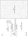
- FIGS. 1A and 1B show a first device 100 that is configured for tracking spatial placement of one or more HF RFID tag objects on a surface, where the transmission antenna 120 is a large single Tx (transmission) antenna (that is large enough to cover all detection fields).
- FIG. 1A shows the partial device (by not including the multiple reception antennas 130), while FIG. 1B shows the full device (by including the multiple reception antennas 130).
- FIGS. 1A and 1B show that device 100 includes a HF RFID reader IC (integrated circuit) 110, a transmission antenna 120, multiple reception antennas 130, Rx path 144, Rx matching unit 140, Tx path 154, Tx tuning unit 150, and a switching unit 160.
- the HF RFID reader IC 110 powers the single transmission antenna 120 through the Tx path 154.
- the transmission antenna effectively transmits power and data over an area that is defined to be a detection surface. To a first approximation, the transmission antenna effectively transmits power over an area that is roughly equivalent to the 2-D (2-dimensional) dimensions of the transmission antenna. However, in practice, the actual "effective" area is larger, since the RF fields can extend beyond the 2-D dimensions of the transmission antenna.
- the actual "effective" area is the area within which the HF RFID tag object can be effectively powered by the transmission antenna.
- the condition is that the one or more HF RFID tag objects are effectively powered by the transmission antenna within the detection surface.
- the transmission antenna transmits power in a 3-D (3-dimensional) manner, so that the transmission antenna is actually effectively transmitting power over a volume. Therefore, more generally, the transmission antenna effectively transmits power and data over an area or a volume that is defined to be a detection range. This detection range would be larger than the 3-D (3-dimensional) dimensions of the transmission antenna, since the RF fields can extend beyond the 3-D dimensions of the transmission antenna. Therefore, the detection range is the actual "effective" volume within which the HF RFID tag object can be effectively powered by the transmission antenna. In other words, the condition is that the one or more HF RFID tag objects are effectively powered by the transmission antenna within the detection range.
- the transmission antenna is constantly transmitting power.
- the detection surface is a flat surface. In one embodiment, the detection surface is a curved surface. In one embodiment, the detection surface is a combination of flat and curved surfaces.
- the Tx (transmission) path 154 consist of a single large antenna 120, while several smaller antennas are used for the Rx (reception) path 144, where each Rx antenna covers one detection field.
- the detection fields are shown to be detection field 1 (132), detection field 2 (134), and detection field N (136).
- N equals 3, but in general N can be any number, depending on how precise (or to what resolution) does the user wish to track the spatial placement of the HF RFID tag objects. If N is large, then the spatial resolution would be high, and the placement tracking more precise. If N is small, then the spatial resolution would be low, and the placement tracking less precise. But, of course, with a single HF RFID reader and a switching unit, then a large N will slow the device down. The device can be sped up with multiple HF RFID readers, but then the cost and design complexity will also go up.
- a switching unit 160 is used to connect the multiple reception antennas to the single HF RFID reader.
- the switching unit 160 is a multiplexer.
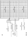
- FIGS. 2A and 2B show a second device 200 that is configured for tracking spatial placement of one or more HF RFID tag objects on a surface, where the transmission antenna 220 is split into smaller sections.
- FIG. 2A shows the partial device (by not including the multiple reception antennas), while FIG. 2B shows the full device (by including the multiple reception antennas). More generally, FIGS. 2A and 2B shows an example of a sectional antenna for the Tx path, which is generating a solid RF field distribution within each detecting field, where the Tx path antenna consists of several small sections.
- FIGS. 2A and 2B show that device 200 includes a HF RFID reader IC 210, a transmission antenna 220, multiple reception antennas, Rx path 244, Rx matching unit 240, Tx path 254, Tx tuning unit 250, and a switching unit 260.
- the HF RFID reader IC 210 powers the single transmission antenna 220 through the Tx path 254.
- Device 200 is very similar to device 100, except the transmission antenna 220 is made up of several small sections: transmission antenna section 1 (222), transmission antenna section 2 (224), and transmission antenna section 3 (226).
- Device 200 only shows three small sections for transmission antenna 220, but other numbers of sections are also possible.
- the three small sections for transmission antenna 220 are shaped as rectangles, but other shapes are also possible.
- the transmission antenna and the small transmission antenna sections can have the following shapes: circle, square, daisy, rectangle, or some other shapes.
- the number of small sections and shapes can be dependent on the particular application of the device configured for tracking spatial placement of HF RFID tag objects on a surface.
- the Rx (reception) path 244 consists of several smaller antennas, where each Rx antenna covers one detection field.
- the detection fields are shown to be detection field 1 (232), detection field 2 (234), and detection field N (236).
- N equals 3, but in general N can be any number, depending on how precise (or to what resolution) the user wishes to track the spatial placement of the HF RFID tag objects.
- FIGS. 3A and 3B show a third device 300 that is configured for tracking spatial placement of one or more HF RFID tag objects on a surface, where the transmission antenna is split into three smaller sections shaped like a daisy.
- FIG. 3A shows the partial device (by not including the multiple reception antennas), while FIG. 3B shows the full device (by including the multiple reception antennas).
- FIGS. 3A and 3B shows an example of a sectional antenna for the Tx path, which is generating a solid RF field distribution within each detecting field, where the Tx path antenna is shaped like a daisy. This shows that various shapes are possible for both the transmission and the reception antennas.
- FIGS. 3A and 3B show that device 300 includes a HF RFID reader IC 310, a transmission antenna with several small sections, multiple reception antennas, Rx path 344, Rx matching unit 340, Tx path 354, Tx tuning unit 350, a switching unit 260, and a platform 370.
- the HF RFID reader IC 310 powers a single transmission antenna through the Tx path 354.
- Device 300 is very similar to device 200, except the transmission antenna (which includes three small sections) is now shaped like a daisy, instead of the rectangle shapes shown in device 200.
- the transmission antenna is made up of several small sections: transmission antenna section 1 (322), transmission antenna section 2 (324), and transmission antenna section 3 (326).
- the Rx (reception) path 344 consists of several smaller antennas, where each Rx antenna covers one detection field.
- the detection fields are shown to be detection field 1 (332), detection field 2 (334), and detection field N (336), where N equals 3.
- FIGS. 3A and 3B also show a platform 370, which can be used to house the transmission and reception antennas, as well as provide support for the one or more RFID tag objects.
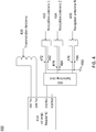
- FIG. 4 shows a fourth device 400 that is configured for tracking spatial placement of one or more HF RFID tag objects on a surface, where each of the multiple reception antennas has one end tied to Ground potential.
- device 400 includes a HF RFID reader IC 410, a transmission antenna 420, multiple reception antennas (432, 434, 436), and a switching unit 460.
- the transmission antenna 420 is connected to the HF RFID reader IC 410 through two connections on HF RFID reader IC 410: Tx1 (412) and Tx2 (414).
- the reception antennas (432, 434, 436) are connected to the HF RFID reader IC 410 through a switching unit 460.
- each one of the plurality of reception antennas (432, 434, 436) has a first output (482, 484, 486) that is connected to a common ground 490 and a second output (472, 474, 476) that is connected to connection Rx1 (416) on HF RFID reader IC 410 via the switching unit 460.
- FIG. 5 shows a fifth device 500 that is configured for tracking spatial placement of one or more HF RFID tag objects on a surface, where each of the multiple reception antennas has both ends of the reception antenna tied to the switching unit (e.g., a multiplexer).
- device 500 includes a HF RFID reader IC 510, a transmission antenna 520, multiple reception antennas (532, 534, 536), and a switching unit 560.
- the transmission antenna 520 is connected to the HF RFID reader IC 510 through two connections on HF RFID reader IC 510: Tx1 (512) and Tx2 (514).
- the reception antennas (532, 534, 536) are connected to the HF RFID reader IC 510 through a switching unit 560.
- each one of the plurality of reception antennas (532, 534, 536) has both outputs (582, 584, 586, 572, 574, 576) that are connected to connections Rx1 (516) and Rx2 (518) on HF RFID reader IC 510 via the switching unit 560.
- Outputs 572, 574, 576 are connected to Rx1 (516) on HF RFID reader IC 510 via the switching unit 560, while outputs 582, 584, 586 are connected to Rx2 (518) on HF RFID reader IC 510 via the switching unit 560
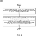
- FIG. 6 shows a flow chart of method steps for tracking spatial placement of an RFID tag object on a surface, in accordance with some example embodiments.
- the method 600 begins at step 610, where the method constantly transmits power and data from a transmission antenna, wherein the transmission antenna effectively transmits power and data over an area that is defined to be a detection surface. Then, the method proceeds to step 620.
- the method utilizes a plurality of reception antennas to detect the spatial placement of the RFID tag object on the detection surface, wherein each one of the plurality of reception antennas is able to effectively receive data from a portion of the detection surface, wherein the spatial placement is determined based on which one of the plurality of reception antennas detects the RFID tag object.
Description
- The described embodiments relate generally to devices and methods that provide for tracking of RFID (Radio-frequency identification) tag objects, and more particularly to devices and methods that provide for tracking spatial placement of HF RFID tag objects on a surface using multiple reception antennas.
- RFID (Radio-frequency identification) applications sometimes require the ability to detect location of an RFID tag object on an RFID reader surface. To solve this requirement, as an example, typically an HF (High frequency) RFID reader uses multiple antennas, where each single antenna has the function of both RF (Radio-frequency) Field & Data transmission and Data reception to/from the HF RFID tag object. For example, if a user wants to detect an HF RFID tag object on 10 different surface locations, then 10 Transmission/Reception antennas are used, where each antenna represents one physical location. Switching Transmission antennas is rather complex due to the high voltage conditions on the antenna coil and requirement to stay perfectly tuned to a given frequency, such as 13.56 MHz, to ensure best energy transfer. HF RFID tag objects can be powered as long as the antenna is active. Once the system switches to another antenna, then the HF RFID tag object on a previous antenna loses power (i.e., is being deactivated). As a consequence of instant switching of the Transmission antenna, the detection loop is slow since it has to reactivate the HF RFID tag object every time the antenna is switched on. Furthermore, it prevents constant energy harvesting from the RF field of the reader.
- Therefore, it is desirable to have devices and methods that can overcome the following list of challenges:
- 1. Switching of Tx/Rx (Transmission/Reception) antenna under high voltage conditions
- 2. Slow detection loop due to reactivation of HF RFID tag object after each antenna switch
- 3. Interrupted energy harvesting
-
US 2015/116091 A1 describes a device aimed for locating in real time self-powered mobile elements by electromagnetic radiation, which includes elements for receiving a radioelectric signal including at least one item of synchronization information, these elements being configured to receive energy from a received radioelectric signal, elements for emitting an electromagnetic signal, the electromagnetic signal being emitted in response to an activation signal, and control elements connected to the receiving elements and to the elements for emitting an electromagnetic signal, the control elements being electrically powered by the elements for receiving a radioelectric signal and being configured to generate an activation signal in response to synchronization information. -
EP 1 607 851 A2 - This specification discloses devices and methods for tracking spatial placement of HF (High frequency) RFID (Radio-frequency identification) tag objects on a surface that use separate transmission and reception antennas. In one embodiment, the device consists of one transmission antenna that only transmits RF (Radio-frequency identification) field and data to the HF RFID tag object. The transmission antenna can be large enough, to cover all detection fields (as shown in
FIG. 1A and1B ), or the transmission antenna can be split into smaller sections (as shown inFIG. 2A and2B ). When using a single transmission antenna, all the HF RFID tag objects are constantly powered, which enables uninterrupted energy harvesting and eliminates the need for continuous activation/deactivation loop. - To track HF RFID tag object on a surface, multiple reception antennas are used. Each detection field has one reception antenna, which is connected to a reception antenna multiplexer. Compared to traditional solutions, only reception antennas are being switched. Due to low voltage conditions on the reception antenna coil, a simple off-the-shelf analog multiplexer can be used. In one embodiment, the reception antenna can be switched single ended (as shown in
FIG. 4 ), where one end of the reception antenna is tied to Ground potential. In another embodiment, configuration with differential reception antenna (as shown inFIG. 5 ) can be applied. - All disclosed embodiments enjoy the advantages of overcoming the following list of challenges:
- 1. Switching of Tx/Rx (Transmission/Reception) antenna under high voltage conditions
- 2. Slow detection loop due to reactivation of HF RFID tag object after each antenna switch
- 3. Interrupted energy harvesting
- In one embodiment, a device configured for tracking spatial placement of one or more HF (High frequency) RFID (Radio-frequency identification) tag objects on a surface is disclosed. The device includes an HF RFID reader, a transmission antenna, and a plurality of reception antennas. The transmission antenna effectively transmits power and data over an area that is defined to be a detection surface. The one or more HF RFID tag objects are effectively powered by the transmission antenna within the detection surface. Each one of the plurality of reception antennas is able to effectively receive data from a portion of the detection surface. In one embodiment, the transmission antenna is constantly transmitting power. In one embodiment, the transmission antenna has one of the following shapes: circle, square, daisy, rectangle. In one embodiment, the detection surface is a flat surface, a curved surface, or a combination of flat and curved surfaces. In one embodiment, each one of the plurality of reception antennas is able to effectively receive data from a separate portion of the detection surface. In one embodiment, all of the plurality of reception antennas together are able to effectively receive data from substantially all of the detection surface. In one embodiment, all of the plurality of reception antennas together are able to effectively receive data from only a part of the detection surface. In one embodiment, the device further includes a switching unit configured to connect the HF RFID reader to one of the plurality of reception antennas. In one embodiment, each one of the plurality of reception antennas has a first output that is connected to a common ground and a second output that is connected to the switching unit. In one embodiment, each one of the plurality of reception antennas has both outputs that are connected to the switching unit.
- In one embodiment, a device configured for tracking spatial placement of one or more RFID (Radio-frequency identification) tag objects within a detection range is disclosed. The device includes an RFID reader, a transmission antenna, and a plurality of reception antennas. The transmission antenna effectively transmits power over an area or a volume that is defined to be a detection range. The one or more RFID tag objects are effectively powered by the transmission antenna within the detection range. Each one of the plurality of reception antennas is able to effectively receive data from a portion of the detection surface. In one embodiment, the transmission antenna is constantly transmitting power. In one embodiment, each one of the plurality of reception antennas is able to effectively receive data from a separate portion of the detection range. In one embodiment, all of the plurality of reception antennas together are able to effectively receive data from substantially all of the detection range. In one embodiment, the RFID reader is an HF (High frequency) RFID reader, and the one or more RFID tag objects are HF RFID tag objects.
- In one embodiment, a method for tracking spatial placement of an RFID (Radio-frequency identification) tag object on a surface is disclosed. The method includes transmitting power and data from a transmission antenna, where the transmission antenna effectively transmits power and data over an area that is defined to be a detection surface. The method further includes utilizing a plurality of reception antennas to detect the spatial placement of the RFID tag object on the detection surface. Each one of the plurality of reception antennas is able to effectively receive data from a portion of the detection surface. The spatial placement is determined based on which one of the plurality of reception antennas detects the RFID tag object. In one embodiment, power is constantly transmitted. In one embodiment, each one of the plurality of reception antennas is able to effectively receive data from a separate portion of the detection surface. In one embodiment, all of the plurality of reception antennas together are able to effectively receive data from substantially all of the detection surface. In one embodiment, the step of utilizing a plurality of reception antennas to detect the spatial placement of the RFID tag object on the detection surface includes utilizing a switching unit to connect an RFID reader to each one of the plurality of reception antennas. In one embodiment, the RFID reader is an HF (High frequency) RFID reader, and the RFID tag object is an HF RFID tag object.
- The above summary is not intended to represent every example embodiment within the scope of the current or future Claim sets. Additional example embodiments are discussed within the Figures and Detailed Description below.
- The described embodiments and the advantages thereof may best be understood by reference to the following description taken in conjunction with the accompanying drawings. These drawings in no way limit any changes in form and detail that may be made to the described embodiments by one skilled in the art without departing from the spirit and scope of the described embodiments.
-
FIGS. 1A and1B show a first device that is configured for tracking spatial placement of one or more HF RFID tag objects on a surface, where the transmission antenna is large enough to cover all detection fields, in accordance with some example embodiments.FIG. 1A shows the partial device (by not including the multiple reception antennas), whileFIG. 1B shows the full device (by including the multiple reception antennas). -
FIGS. 2A and2B show a second device that is configured for tracking spatial placement of one or more HF RFID tag objects on a surface, where the transmission antenna is split into smaller sections, in accordance with some example embodiments.FIG. 2A shows the partial device (by not including the multiple reception antennas), whileFIG. 2B shows the full device (by including the multiple reception antennas). -
FIGS. 3A and3B show a third device that is configured for tracking spatial placement of one or more HF RFID tag objects on a surface, where the transmission antenna is split into three smaller sections shaped like a daisy, in accordance with some example embodiments.FIG. 3A shows the partial device (by not including the multiple reception antennas), whileFIG. 3B shows the full device (by including the multiple reception antennas). -
FIG. 4 shows a fourth device that is configured for tracking spatial placement of one or more HF RFID tag objects on a surface, where each of the multiple reception antennas has one end tied to Ground potential, in accordance with some example embodiments. -
FIG. 5 shows a fifth device that is configured for tracking spatial placement of one or more HF RFID tag objects on a surface, where each of the multiple reception antennas has both ends of the reception antenna tied to the switching unit (e.g., a multiplexer), in accordance with some example embodiments. -
FIG. 6 shows a flow chart of method steps for tracking spatial placement of an RFID tag object on a surface, in accordance with some example embodiments. - Representative devices and methods according to the present application are described in this section. These examples are being provided solely to add context and aid in the understanding of the described embodiments. It will thus be apparent to one skilled in the art that the described embodiments may be practiced without some or all of these specific details. In other instances, well known process steps have not been described in detail in order to avoid unnecessarily obscuring the described embodiments. Other embodiments are possible, such that the following examples should not be taken as limiting.
- In the following detailed description, references are made to the accompanying drawings, which form a part of the description and in which are shown, by way of illustration, specific embodiments in accordance with the described embodiments. Although these embodiments are described in sufficient detail to enable one skilled in the art to practice the described embodiments, it is understood that these examples are not limiting; such that other embodiments may be used, and changes may be made without departing from the spirit and scope of the described embodiments.
- One of the key disclosure is the usage of multiple data Reception antennas for localizing the HF RFID tag objects on a surface, while keeping the number of Transmission antenna at one. With such a configuration, only a single transmission antenna transmits RF field and data to the HF RFID tag object, while multiple reception antennas are used to track HF RFID tag object on the surface. In one embodiment, the single transmission antenna can be large enough, to cover all detection fields. In another embodiment, the transmission antenna can be split into smaller sections. When using a single transmission antenna, all the HF RFID tag objects are constantly powered, which enables uninterrupted energy harvesting and eliminates the slow detection loop due to reactivation of HF RFID tag object after each antenna switch. There is also the advantage that there are no longer any need for the switching of Tx/Rx (Transmission/Reception) antenna under high voltage conditions, since all antennas are now either a Tx (Transmission) antenna or a Rx (Reception) antenna.
- To track HF RFID tag object on a surface, multiple reception antennas are used, so that each detection field has one reception antenna. In order to reduce cost and simplify the design, the device uses only one HF RFID reader. A switching unit, such as a multiplexer, can be used to connect the multiple reception antennas to the single HF RFID reader. In one embodiment, the switching unit can sequentially connect each reception antennas to the single HF RFID reader. This can be done using a fixed switching frequency, so that each reception antenna is only connected for a fixed amount of time. Or, alternatively, the switching frequency can be varying, and the connect time can be also varying. Or, an algorithm can be applied to perform this switching. The reception antenna coil functions under low voltage conditions, so a simple standard analog multiplexer can be used. In one embodiment, the reception antenna has one output connected to the switching unit and a second output connected to a common ground potential. In another embodiment, the reception antenna has both outputs connected to the switching unit.
-
FIGS. 1A and1B show afirst device 100 that is configured for tracking spatial placement of one or more HF RFID tag objects on a surface, where thetransmission antenna 120 is a large single Tx (transmission) antenna (that is large enough to cover all detection fields).FIG. 1A shows the partial device (by not including the multiple reception antennas 130), whileFIG. 1B shows the full device (by including the multiple reception antennas 130). -
FIGS. 1A and1B show thatdevice 100 includes a HF RFID reader IC (integrated circuit) 110, atransmission antenna 120,multiple reception antennas 130,Rx path 144,Rx matching unit 140,Tx path 154,Tx tuning unit 150, and aswitching unit 160. The HFRFID reader IC 110 powers thesingle transmission antenna 120 through theTx path 154. The transmission antenna effectively transmits power and data over an area that is defined to be a detection surface. To a first approximation, the transmission antenna effectively transmits power over an area that is roughly equivalent to the 2-D (2-dimensional) dimensions of the transmission antenna. However, in practice, the actual "effective" area is larger, since the RF fields can extend beyond the 2-D dimensions of the transmission antenna. Therefore, the actual "effective" area (i.e., the detection surface) is the area within which the HF RFID tag object can be effectively powered by the transmission antenna. In other words, the condition is that the one or more HF RFID tag objects are effectively powered by the transmission antenna within the detection surface. Furthermore, more generally, the transmission antenna transmits power in a 3-D (3-dimensional) manner, so that the transmission antenna is actually effectively transmitting power over a volume. Therefore, more generally, the transmission antenna effectively transmits power and data over an area or a volume that is defined to be a detection range. This detection range would be larger than the 3-D (3-dimensional) dimensions of the transmission antenna, since the RF fields can extend beyond the 3-D dimensions of the transmission antenna. Therefore, the detection range is the actual "effective" volume within which the HF RFID tag object can be effectively powered by the transmission antenna. In other words, the condition is that the one or more HF RFID tag objects are effectively powered by the transmission antenna within the detection range. - In one embodiment, the transmission antenna is constantly transmitting power. In one embodiment, the detection surface is a flat surface. In one embodiment, the detection surface is a curved surface. In one embodiment, the detection surface is a combination of flat and curved surfaces.
- In
FIGS. 1A and1B , the Tx (transmission)path 154 consist of a singlelarge antenna 120, while several smaller antennas are used for the Rx (reception)path 144, where each Rx antenna covers one detection field. InFIG. 1B , the detection fields are shown to be detection field 1 (132), detection field 2 (134), and detection field N (136). InFIG. 1B , N equals 3, but in general N can be any number, depending on how precise (or to what resolution) does the user wish to track the spatial placement of the HF RFID tag objects. If N is large, then the spatial resolution would be high, and the placement tracking more precise. If N is small, then the spatial resolution would be low, and the placement tracking less precise. But, of course, with a single HF RFID reader and a switching unit, then a large N will slow the device down. The device can be sped up with multiple HF RFID readers, but then the cost and design complexity will also go up. - In
FIGS. 1A and1B , aswitching unit 160 is used to connect the multiple reception antennas to the single HF RFID reader. In one embodiment, theswitching unit 160 is a multiplexer. -
FIGS. 2A and2B show asecond device 200 that is configured for tracking spatial placement of one or more HF RFID tag objects on a surface, where thetransmission antenna 220 is split into smaller sections.FIG. 2A shows the partial device (by not including the multiple reception antennas), whileFIG. 2B shows the full device (by including the multiple reception antennas). More generally,FIGS. 2A and2B shows an example of a sectional antenna for the Tx path, which is generating a solid RF field distribution within each detecting field, where the Tx path antenna consists of several small sections. -
FIGS. 2A and2B show thatdevice 200 includes a HFRFID reader IC 210, atransmission antenna 220, multiple reception antennas,Rx path 244,Rx matching unit 240,Tx path 254,Tx tuning unit 250, and aswitching unit 260. The HFRFID reader IC 210 powers thesingle transmission antenna 220 through theTx path 254.Device 200 is very similar todevice 100, except thetransmission antenna 220 is made up of several small sections: transmission antenna section 1 (222), transmission antenna section 2 (224), and transmission antenna section 3 (226).Device 200 only shows three small sections fortransmission antenna 220, but other numbers of sections are also possible. The three small sections fortransmission antenna 220 are shaped as rectangles, but other shapes are also possible. In other embodiments, the transmission antenna and the small transmission antenna sections can have the following shapes: circle, square, daisy, rectangle, or some other shapes. The number of small sections and shapes can be dependent on the particular application of the device configured for tracking spatial placement of HF RFID tag objects on a surface. - In
FIGS. 2A and2B , the Rx (reception)path 244 consists of several smaller antennas, where each Rx antenna covers one detection field. InFIG. 2B , the detection fields are shown to be detection field 1 (232), detection field 2 (234), and detection field N (236). InFIG. 2B , N equals 3, but in general N can be any number, depending on how precise (or to what resolution) the user wishes to track the spatial placement of the HF RFID tag objects. -
FIGS. 3A and3B show athird device 300 that is configured for tracking spatial placement of one or more HF RFID tag objects on a surface, where the transmission antenna is split into three smaller sections shaped like a daisy.FIG. 3A shows the partial device (by not including the multiple reception antennas), whileFIG. 3B shows the full device (by including the multiple reception antennas). More generally,FIGS. 3A and3B shows an example of a sectional antenna for the Tx path, which is generating a solid RF field distribution within each detecting field, where the Tx path antenna is shaped like a daisy. This shows that various shapes are possible for both the transmission and the reception antennas. -
FIGS. 3A and3B show thatdevice 300 includes a HFRFID reader IC 310, a transmission antenna with several small sections, multiple reception antennas,Rx path 344,Rx matching unit 340, Tx path 354,Tx tuning unit 350, aswitching unit 260, and aplatform 370. The HFRFID reader IC 310 powers a single transmission antenna through the Tx path 354.Device 300 is very similar todevice 200, except the transmission antenna (which includes three small sections) is now shaped like a daisy, instead of the rectangle shapes shown indevice 200. In particular, the transmission antenna is made up of several small sections: transmission antenna section 1 (322), transmission antenna section 2 (324), and transmission antenna section 3 (326). - In
FIGS. 3A and3B , the Rx (reception)path 344 consists of several smaller antennas, where each Rx antenna covers one detection field. InFIG. 3B , the detection fields are shown to be detection field 1 (332), detection field 2 (334), and detection field N (336), where N equals 3. -
FIGS. 3A and3B also show aplatform 370, which can be used to house the transmission and reception antennas, as well as provide support for the one or more RFID tag objects. -
FIG. 4 shows afourth device 400 that is configured for tracking spatial placement of one or more HF RFID tag objects on a surface, where each of the multiple reception antennas has one end tied to Ground potential. In particular,FIG. 4 shows thatdevice 400 includes a HFRFID reader IC 410, atransmission antenna 420, multiple reception antennas (432, 434, 436), and aswitching unit 460. Thetransmission antenna 420 is connected to the HFRFID reader IC 410 through two connections on HF RFID reader IC 410: Tx1 (412) and Tx2 (414). The reception antennas (432, 434, 436) are connected to the HFRFID reader IC 410 through aswitching unit 460. Indevice 400, each one of the plurality of reception antennas (432, 434, 436) has a first output (482, 484, 486) that is connected to acommon ground 490 and a second output (472, 474, 476) that is connected to connection Rx1 (416) on HFRFID reader IC 410 via theswitching unit 460. -
FIG. 5 shows afifth device 500 that is configured for tracking spatial placement of one or more HF RFID tag objects on a surface, where each of the multiple reception antennas has both ends of the reception antenna tied to the switching unit (e.g., a multiplexer). In particular,FIG. 5 shows thatdevice 500 includes a HFRFID reader IC 510, atransmission antenna 520, multiple reception antennas (532, 534, 536), and aswitching unit 560. Thetransmission antenna 520 is connected to the HFRFID reader IC 510 through two connections on HF RFID reader IC 510: Tx1 (512) and Tx2 (514). The reception antennas (532, 534, 536) are connected to the HFRFID reader IC 510 through aswitching unit 560. Indevice 500, each one of the plurality of reception antennas (532, 534, 536) has both outputs (582, 584, 586, 572, 574, 576) that are connected to connections Rx1 (516) and Rx2 (518) on HFRFID reader IC 510 via theswitching unit 560.Outputs RFID reader IC 510 via theswitching unit 560, whileoutputs RFID reader IC 510 via theswitching unit 560 -
FIG. 6 shows a flow chart of method steps for tracking spatial placement of an RFID tag object on a surface, in accordance with some example embodiments. As shown inFIG. 6 , themethod 600 begins atstep 610, where the method constantly transmits power and data from a transmission antenna, wherein the transmission antenna effectively transmits power and data over an area that is defined to be a detection surface. Then, the method proceeds to step 620. Instep 620, the method utilizes a plurality of reception antennas to detect the spatial placement of the RFID tag object on the detection surface, wherein each one of the plurality of reception antennas is able to effectively receive data from a portion of the detection surface, wherein the spatial placement is determined based on which one of the plurality of reception antennas detects the RFID tag object. - In this specification, example embodiments have been presented in terms of a selected set of details. However, a person of ordinary skill in the art would understand that many other example embodiments may be practiced which include a different selected set of these details. It is intended that the following claims cover all possible example embodiments.
- The foregoing description, for purposes of explanation, used specific nomenclature to provide a thorough understanding of the described embodiments. However, it will be apparent to one skilled in the art that the specific details are not required in order to practice the described embodiments. Thus, the foregoing descriptions of specific embodiments are presented for purposes of illustration and description. They are not intended to be exhaustive or to limit the described embodiments to the precise forms disclosed. It will be apparent to one of ordinary skill in the art that many modifications and variations are possible in view of the above teachings.
- The invention is defined by the appended claims.
Claims (14)
- A device (100, 200, 300, 400, 500) configured for tracking spatial placement of one or more High frequency, HF, Radio-frequency identification, RFID, tag objects on a surface, the device comprising:an RFID reader (110, 210, 310, 410, 510);a transmission antenna (120, 220, 420, 520); anda plurality of reception antennas (130, 432, 434, 436, 532, 534, 536),wherein the transmission antenna (120, 220, 420, 520) effectively transmits power and data over an area that is defined to be a detection surface,wherein the one or more RFID tag objects are effectively powered by the transmission antenna (120, 220, 420, 520) within the detection surface,wherein each one of the plurality of reception antennas (130, 432, 434, 436, 532, 534, 536) is able to effectively receive data from an HF RFID tag object positioned on a portion of the detection surface,characterized in that the detection surface comprises a plurality of detection fields and wherein each detection field has one reception antenna (130, 432, 434, 436, 532, 534, 536).
- The device (100, 200, 300, 400, 500) of claim 1,
wherein the transmission antenna (120, 220, 420, 520) is constantly transmitting power. - The device (100, 200, 300, 400, 500) of claim 2,
wherein the transmission antenna (120, 220, 420, 520) has one of the following shapes:
circle, square, daisy, rectangle. - The device (100, 200, 300, 400, 500) of claim 2 or 3,
wherein the detection surface is a flat surface, a curved surface, or a combination of flat and curved surfaces. - The device (100, 200, 300, 400, 500) of any one of claims 2 to 4,
wherein said reception antennas (130, 432, 434, 436, 532, 534, 536) are able to effectively receive data from HF RFID tag objects positioned on distinct portions of the detection surface. - The device (100, 200, 300, 400, 500) of claim 5,
wherein all of the plurality of reception antennas (130, 432, 434, 436, 532, 534, 536) together are able to effectively receive data from HF RFID tag objects positioned on substantially all of the detection surface. - The device (100, 200, 300, 400, 500) of claim 5,
wherein all of the plurality of reception antennas (130, 432, 434, 436, 532, 534, 536) together are able to effectively receive data from HF RFID tag objects positioned on only a part of the detection surface. - The device (100, 200, 300, 400, 500) of any one of claims 2 to 7, further comprising:
a switching unit (160, 260, 360, 460, 560) configured to connect the RFID reader (110, 210, 310, 410, 510) to one of the plurality of reception antennas (130, 432, 434, 436, 532, 534, 536). - The device (100, 200, 300, 400, 500) of claim 8,
wherein each one of the plurality of reception antennas (130, 432, 434, 436, 532, 534, 536) has a first output that is connected to a common ground and a second output that is connected to the switching unit (160, 260, 360, 460, 560). - The device (100, 200, 300, 400, 500) of claim 8,
wherein each one of the plurality of reception antennas (130, 432, 434, 436, 532, 534, 536) has both outputs that are connected to the switching unit (160, 260, 360, 460, 560). - A method for tracking spatial placement of a High frequency, HF, Radio-frequency identification, RFID, tag object on a surface, the method comprising:transmitting power and data from a transmission antenna (120, 220, 420, 520),
wherein the transmission antenna (120, 220, 420, 520) effectively transmits power and data over an area that is defined to be a detection surface;utilizing a plurality of reception antennas (130, 432, 434, 436, 532, 534, 536) to detect the spatial placement of the RFID tag object on the detection surface,wherein each one of the plurality of reception antennas (130, 432, 434, 436, 532, 534, 536) is able to effectively receive data from an HF RFID tag object positioned on a portion of the detection surface,characterized in that the detection surface comprises a plurality of detection fields and wherein each detection field has one reception antenna (130, 432, 434, 436, 532, 534, 536), wherein the spatial placement is determined based on which one of the plurality of reception antennas (130, 432, 434, 436, 532, 534, 536) detects the RFID tag object. - The method of claim 11,
wherein said reception antennas (130, 432, 434, 436, 532, 534, 536) are able to effectively receive data from HF RFID tag objects positioned on distinct portions of the detection surface. - The method of claim 12,
wherein all of the plurality of reception antennas (130, 432, 434, 436, 532, 534, 536) together are able to effectively receive data from an HF RFID tag object positioned on substantially all of the detection surface. - The method of any one of claims 11 to 13, wherein the step of utilizing a plurality of reception antennas (130, 432, 434, 436, 532, 534, 536) to detect the spatial placement of the RFID tag object on the detection surface comprises:
utilizing a switching unit (160, 260, 360, 460, 560) to connect an RFID reader to each one of the plurality of reception antennas (130, 432, 434, 436, 532, 534, 536).
Applications Claiming Priority (1)
| Application Number | Priority Date | Filing Date | Title |
|---|---|---|---|
| US14/855,300 US10078127B2 (en) | 2015-09-15 | 2015-09-15 | Tracking spatial placement of HF RFID tag objects on a surface using multiple reception antennas |
Publications (2)
| Publication Number | Publication Date |
|---|---|
| EP3144847A1 EP3144847A1 (en) | 2017-03-22 |
| EP3144847B1 true EP3144847B1 (en) | 2020-01-01 |
Family
ID=57144719
Family Applications (1)
| Application Number | Title | Priority Date | Filing Date |
|---|---|---|---|
| EP16185741.2A Active EP3144847B1 (en) | 2015-09-15 | 2016-08-25 | Tracking spatial placement of hf rfid tag objects on a surface using multiple reception antennas |
Country Status (3)
| Country | Link |
|---|---|
| US (1) | US10078127B2 (en) |
| EP (1) | EP3144847B1 (en) |
| CN (1) | CN106533510B (en) |
Families Citing this family (5)
| Publication number | Priority date | Publication date | Assignee | Title |
|---|---|---|---|---|
| US10733394B2 (en) * | 2014-12-31 | 2020-08-04 | Intermec Ip Corp. | Smart energy scavenging tag sensor |
| US10955977B2 (en) * | 2015-11-03 | 2021-03-23 | Microsoft Technology Licensing, Llc | Extender object for multi-modal sensing |
| US10649572B2 (en) | 2015-11-03 | 2020-05-12 | Microsoft Technology Licensing, Llc | Multi-modal sensing surface |
| US10338753B2 (en) | 2015-11-03 | 2019-07-02 | Microsoft Technology Licensing, Llc | Flexible multi-layer sensing surface |
| US11714976B2 (en) | 2018-05-01 | 2023-08-01 | Angel Group Co., Ltd. | Antenna switching |
Family Cites Families (26)
| Publication number | Priority date | Publication date | Assignee | Title |
|---|---|---|---|---|
| US7895132B2 (en) * | 2003-12-22 | 2011-02-22 | United Parcel Service Of America, Inc. | Manifest generation and download systems and methods |
| JP4318596B2 (en) | 2004-06-18 | 2009-08-26 | 株式会社ワコム | Position detection device |
| US20060125602A1 (en) | 2004-12-09 | 2006-06-15 | Joshua Posamentier | Active multiplexer for a multiple antenna transceiver |
| US7265675B1 (en) | 2005-03-01 | 2007-09-04 | Alien Technology Corporation | Multistatic antenna configuration for radio frequency identification (RFID) systems |
| JP5058787B2 (en) * | 2005-04-07 | 2012-10-24 | 日本電気株式会社 | RFID system, reader, control program, and transmission method |
| US20060273909A1 (en) | 2005-06-01 | 2006-12-07 | Morad Heiman | RFID-based toy and system |
| US7602288B2 (en) * | 2005-12-01 | 2009-10-13 | Frito-Lay North America, Inc. | Method for slap-and-ship RFID labeling |
| KR101533045B1 (en) * | 2006-07-10 | 2015-07-02 | 인티그리스, 인코포레이티드 | Systems and methods for managing material storage vessels having information storage elements |
| WO2008118875A1 (en) * | 2007-03-23 | 2008-10-02 | Mojix, Inc. | Rfid systems using distributed exciter network |
| EP2206277A4 (en) * | 2007-10-22 | 2013-02-13 | Microlatch Pty Ltd | A transmitter for transmitting a secure access signal |
| CN101320092A (en) * | 2008-07-16 | 2008-12-10 | 黄以华 | Positioning method based on wireless radio frequency recognition technology |
| JP5012933B2 (en) * | 2010-02-26 | 2012-08-29 | カシオ計算機株式会社 | Mobile terminal and program |
| CN103150527B (en) * | 2011-12-06 | 2016-03-30 | 富士通株式会社 | RFID tag localization method and equipment and RFID tag reader |
| US9436857B2 (en) * | 2012-01-16 | 2016-09-06 | Hand Held Products, Inc. | Encoded information reading system including RFID reading device having multiple antennas |
| WO2013126391A1 (en) * | 2012-02-22 | 2013-08-29 | Bar Code Specialties, Inc. (Dba Bcs Solutions) | Overhead antenna live inventory locating system |
| US20130229262A1 (en) * | 2012-03-05 | 2013-09-05 | Symbol Technologies, Inc. | Radio frequency identification reader antenna arrangement with multiple linearly-polarized elements |
| FR2991800B1 (en) * | 2012-06-07 | 2014-07-04 | Epawn | DEVICE FOR REAL-TIME LOCALIZATION OF A SELF-POWERED MOBILE ELEMENT |
| WO2014052907A1 (en) * | 2012-09-27 | 2014-04-03 | Seeonic, Inc. | Modular rfid tag scanner for a product storage system |
| US9575156B2 (en) | 2013-01-15 | 2017-02-21 | Disney Enterprises, Inc. | Spatial recognition of RFID tag placement using antenna multiplexing |
| CN104303133A (en) | 2013-03-12 | 2015-01-21 | 施政 | System and method for interactive board |
| WO2015024223A1 (en) * | 2013-08-21 | 2015-02-26 | Zhang Wei | Intelligent safe box, safe control system and control method using same |
| KR102091513B1 (en) * | 2013-11-12 | 2020-04-14 | 한국전자통신연구원 | Apparatus and method for receiving of rfid reader |
| WO2015148509A1 (en) * | 2014-03-27 | 2015-10-01 | The Coca-Cola Company | Determining an inventory using positional and non-positional awareness |
| US20150370745A1 (en) * | 2014-06-20 | 2015-12-24 | Key Systems, Inc. | System and method for communication port based asset management |
| CN104198990B (en) * | 2014-09-23 | 2017-05-10 | 天津工业大学 | RFID (radio frequency identification devices) positioning system capable of expanding positioning range |
| US10733394B2 (en) * | 2014-12-31 | 2020-08-04 | Intermec Ip Corp. | Smart energy scavenging tag sensor |
-
2015
- 2015-09-15 US US14/855,300 patent/US10078127B2/en active Active
-
2016
- 2016-08-25 EP EP16185741.2A patent/EP3144847B1/en active Active
- 2016-09-06 CN CN201610806689.6A patent/CN106533510B/en active Active
Non-Patent Citations (1)
| Title |
|---|
| None * |
Also Published As
| Publication number | Publication date |
|---|---|
| CN106533510B (en) | 2021-11-05 |
| EP3144847A1 (en) | 2017-03-22 |
| US20170074966A1 (en) | 2017-03-16 |
| CN106533510A (en) | 2017-03-22 |
| US10078127B2 (en) | 2018-09-18 |
Similar Documents
| Publication | Publication Date | Title |
|---|---|---|
| EP3144847B1 (en) | Tracking spatial placement of hf rfid tag objects on a surface using multiple reception antennas | |
| Ma et al. | 3D real-time indoor localization via broadband nonlinear backscatter in passive devices with centimeter precision | |
| US10445539B2 (en) | UHF band RFID system and UHF band RFID tag detection method | |
| ES2373162T3 (en) | RADIO FREQUENCY IDENTIFICATION READER THAT HAS A SIGNAL AND METHOD NULLER. | |
| EP3451453B1 (en) | Wireless power transmission device and control method therefor | |
| EP1901202B1 (en) | RF Tag reader and reading method | |
| US8115637B2 (en) | Systems and methods to selectively connect antennas to receive and backscatter radio frequency signals | |
| US20110068987A1 (en) | Multiband RFID tag | |
| US9575156B2 (en) | Spatial recognition of RFID tag placement using antenna multiplexing | |
| US10374465B2 (en) | Wireless power transmitter and control method therefor | |
| US8270911B2 (en) | Communications methods, methods of forming a reader, wireless communications readers, and wireless communications systems | |
| DK2256663T3 (en) | Activation of a contactless device by means of a capacitive device | |
| US10430623B1 (en) | RFID tag tracking using tag population management | |
| US9735464B2 (en) | System and method for tracking | |
| JP2011125016A (en) | Device for locating object by rfid communication | |
| US11039538B2 (en) | Communication system including antennas on flexible circuit board | |
| US9323965B2 (en) | Method for choosing RFID communication mode and RFID device which supports near-field and far-field communication | |
| EP3163511B1 (en) | Multi-band rfid device | |
| US11424554B2 (en) | Antenna device | |
| US20200144479A1 (en) | Piezoelectric rf identification (rfid) antennas | |
| KR20140119534A (en) | Rfid tag applying conductive loop | |
| Qing et al. | UHF near-field segmented loop antennas with enlarged interrogation zone | |
| CN109154999B (en) | Transponder, in particular RFID transponder, and method for operating a transponder, in particular an RFID transponder | |
| Dhaouadi et al. | Magnetic antenna for near-field UHF RFID tag | |
| González et al. | RFID tag antenna design applied to the public health system as identification alternative |
Legal Events
| Date | Code | Title | Description |
|---|---|---|---|
| PUAI | Public reference made under article 153(3) epc to a published international application that has entered the european phase |
Free format text: ORIGINAL CODE: 0009012 |
|
| STAA | Information on the status of an ep patent application or granted ep patent |
Free format text: STATUS: THE APPLICATION HAS BEEN PUBLISHED |
|
| AK | Designated contracting states |
Kind code of ref document: A1 Designated state(s): AL AT BE BG CH CY CZ DE DK EE ES FI FR GB GR HR HU IE IS IT LI LT LU LV MC MK MT NL NO PL PT RO RS SE SI SK SM TR |
|
| AX | Request for extension of the european patent |
Extension state: BA ME |
|
| STAA | Information on the status of an ep patent application or granted ep patent |
Free format text: STATUS: REQUEST FOR EXAMINATION WAS MADE |
|
| 17P | Request for examination filed |
Effective date: 20170922 |
|
| RBV | Designated contracting states (corrected) |
Designated state(s): AL AT BE BG CH CY CZ DE DK EE ES FI FR GB GR HR HU IE IS IT LI LT LU LV MC MK MT NL NO PL PT RO RS SE SI SK SM TR |
|
| STAA | Information on the status of an ep patent application or granted ep patent |
Free format text: STATUS: EXAMINATION IS IN PROGRESS |
|
| 17Q | First examination report despatched |
Effective date: 20180130 |
|
| GRAP | Despatch of communication of intention to grant a patent |
Free format text: ORIGINAL CODE: EPIDOSNIGR1 |
|
| STAA | Information on the status of an ep patent application or granted ep patent |
Free format text: STATUS: GRANT OF PATENT IS INTENDED |
|
| RIC1 | Information provided on ipc code assigned before grant |
Ipc: G06F 3/046 20060101ALI20190909BHEP Ipc: G06F 3/041 20060101ALI20190909BHEP Ipc: G06K 7/10 20060101AFI20190909BHEP |
|
| INTG | Intention to grant announced |
Effective date: 20190930 |
|
| GRAS | Grant fee paid |
Free format text: ORIGINAL CODE: EPIDOSNIGR3 |
|
| GRAA | (expected) grant |
Free format text: ORIGINAL CODE: 0009210 |
|
| STAA | Information on the status of an ep patent application or granted ep patent |
Free format text: STATUS: THE PATENT HAS BEEN GRANTED |
|
| AK | Designated contracting states |
Kind code of ref document: B1 Designated state(s): AL AT BE BG CH CY CZ DE DK EE ES FI FR GB GR HR HU IE IS IT LI LT LU LV MC MK MT NL NO PL PT RO RS SE SI SK SM TR |
|
| REG | Reference to a national code |
Ref country code: GB Ref legal event code: FG4D |
|
| REG | Reference to a national code |
Ref country code: CH Ref legal event code: EP Ref country code: AT Ref legal event code: REF Ref document number: 1220721 Country of ref document: AT Kind code of ref document: T Effective date: 20200115 |
|
| REG | Reference to a national code |
Ref country code: IE Ref legal event code: FG4D |
|
| REG | Reference to a national code |
Ref country code: DE Ref legal event code: R096 Ref document number: 602016027186 Country of ref document: DE |
|
| REG | Reference to a national code |
Ref country code: NL Ref legal event code: MP Effective date: 20200101 |
|
| REG | Reference to a national code |
Ref country code: LT Ref legal event code: MG4D |
|
| PG25 | Lapsed in a contracting state [announced via postgrant information from national office to epo] |
Ref country code: LT Free format text: LAPSE BECAUSE OF FAILURE TO SUBMIT A TRANSLATION OF THE DESCRIPTION OR TO PAY THE FEE WITHIN THE PRESCRIBED TIME-LIMIT Effective date: 20200101 Ref country code: RS Free format text: LAPSE BECAUSE OF FAILURE TO SUBMIT A TRANSLATION OF THE DESCRIPTION OR TO PAY THE FEE WITHIN THE PRESCRIBED TIME-LIMIT Effective date: 20200101 Ref country code: NO Free format text: LAPSE BECAUSE OF FAILURE TO SUBMIT A TRANSLATION OF THE DESCRIPTION OR TO PAY THE FEE WITHIN THE PRESCRIBED TIME-LIMIT Effective date: 20200401 Ref country code: FI Free format text: LAPSE BECAUSE OF FAILURE TO SUBMIT A TRANSLATION OF THE DESCRIPTION OR TO PAY THE FEE WITHIN THE PRESCRIBED TIME-LIMIT Effective date: 20200101 Ref country code: NL Free format text: LAPSE BECAUSE OF FAILURE TO SUBMIT A TRANSLATION OF THE DESCRIPTION OR TO PAY THE FEE WITHIN THE PRESCRIBED TIME-LIMIT Effective date: 20200101 Ref country code: PT Free format text: LAPSE BECAUSE OF FAILURE TO SUBMIT A TRANSLATION OF THE DESCRIPTION OR TO PAY THE FEE WITHIN THE PRESCRIBED TIME-LIMIT Effective date: 20200527 Ref country code: CZ Free format text: LAPSE BECAUSE OF FAILURE TO SUBMIT A TRANSLATION OF THE DESCRIPTION OR TO PAY THE FEE WITHIN THE PRESCRIBED TIME-LIMIT Effective date: 20200101 |
|
| PG25 | Lapsed in a contracting state [announced via postgrant information from national office to epo] |
Ref country code: HR Free format text: LAPSE BECAUSE OF FAILURE TO SUBMIT A TRANSLATION OF THE DESCRIPTION OR TO PAY THE FEE WITHIN THE PRESCRIBED TIME-LIMIT Effective date: 20200101 Ref country code: GR Free format text: LAPSE BECAUSE OF FAILURE TO SUBMIT A TRANSLATION OF THE DESCRIPTION OR TO PAY THE FEE WITHIN THE PRESCRIBED TIME-LIMIT Effective date: 20200402 Ref country code: LV Free format text: LAPSE BECAUSE OF FAILURE TO SUBMIT A TRANSLATION OF THE DESCRIPTION OR TO PAY THE FEE WITHIN THE PRESCRIBED TIME-LIMIT Effective date: 20200101 Ref country code: SE Free format text: LAPSE BECAUSE OF FAILURE TO SUBMIT A TRANSLATION OF THE DESCRIPTION OR TO PAY THE FEE WITHIN THE PRESCRIBED TIME-LIMIT Effective date: 20200101 Ref country code: IS Free format text: LAPSE BECAUSE OF FAILURE TO SUBMIT A TRANSLATION OF THE DESCRIPTION OR TO PAY THE FEE WITHIN THE PRESCRIBED TIME-LIMIT Effective date: 20200501 Ref country code: BG Free format text: LAPSE BECAUSE OF FAILURE TO SUBMIT A TRANSLATION OF THE DESCRIPTION OR TO PAY THE FEE WITHIN THE PRESCRIBED TIME-LIMIT Effective date: 20200401 |
|
| REG | Reference to a national code |
Ref country code: DE Ref legal event code: R097 Ref document number: 602016027186 Country of ref document: DE |
|
| PG25 | Lapsed in a contracting state [announced via postgrant information from national office to epo] |
Ref country code: RO Free format text: LAPSE BECAUSE OF FAILURE TO SUBMIT A TRANSLATION OF THE DESCRIPTION OR TO PAY THE FEE WITHIN THE PRESCRIBED TIME-LIMIT Effective date: 20200101 Ref country code: SK Free format text: LAPSE BECAUSE OF FAILURE TO SUBMIT A TRANSLATION OF THE DESCRIPTION OR TO PAY THE FEE WITHIN THE PRESCRIBED TIME-LIMIT Effective date: 20200101 Ref country code: DK Free format text: LAPSE BECAUSE OF FAILURE TO SUBMIT A TRANSLATION OF THE DESCRIPTION OR TO PAY THE FEE WITHIN THE PRESCRIBED TIME-LIMIT Effective date: 20200101 Ref country code: ES Free format text: LAPSE BECAUSE OF FAILURE TO SUBMIT A TRANSLATION OF THE DESCRIPTION OR TO PAY THE FEE WITHIN THE PRESCRIBED TIME-LIMIT Effective date: 20200101 Ref country code: EE Free format text: LAPSE BECAUSE OF FAILURE TO SUBMIT A TRANSLATION OF THE DESCRIPTION OR TO PAY THE FEE WITHIN THE PRESCRIBED TIME-LIMIT Effective date: 20200101 Ref country code: SM Free format text: LAPSE BECAUSE OF FAILURE TO SUBMIT A TRANSLATION OF THE DESCRIPTION OR TO PAY THE FEE WITHIN THE PRESCRIBED TIME-LIMIT Effective date: 20200101 |
|
| PLBE | No opposition filed within time limit |
Free format text: ORIGINAL CODE: 0009261 |
|
| STAA | Information on the status of an ep patent application or granted ep patent |
Free format text: STATUS: NO OPPOSITION FILED WITHIN TIME LIMIT |
|
| REG | Reference to a national code |
Ref country code: AT Ref legal event code: MK05 Ref document number: 1220721 Country of ref document: AT Kind code of ref document: T Effective date: 20200101 |
|
| 26N | No opposition filed |
Effective date: 20201002 |
|
| PG25 | Lapsed in a contracting state [announced via postgrant information from national office to epo] |
Ref country code: AT Free format text: LAPSE BECAUSE OF FAILURE TO SUBMIT A TRANSLATION OF THE DESCRIPTION OR TO PAY THE FEE WITHIN THE PRESCRIBED TIME-LIMIT Effective date: 20200101 Ref country code: IT Free format text: LAPSE BECAUSE OF FAILURE TO SUBMIT A TRANSLATION OF THE DESCRIPTION OR TO PAY THE FEE WITHIN THE PRESCRIBED TIME-LIMIT Effective date: 20200101 |
|
| PG25 | Lapsed in a contracting state [announced via postgrant information from national office to epo] |
Ref country code: SI Free format text: LAPSE BECAUSE OF FAILURE TO SUBMIT A TRANSLATION OF THE DESCRIPTION OR TO PAY THE FEE WITHIN THE PRESCRIBED TIME-LIMIT Effective date: 20200101 Ref country code: PL Free format text: LAPSE BECAUSE OF FAILURE TO SUBMIT A TRANSLATION OF THE DESCRIPTION OR TO PAY THE FEE WITHIN THE PRESCRIBED TIME-LIMIT Effective date: 20200101 |
|
| PG25 | Lapsed in a contracting state [announced via postgrant information from national office to epo] |
Ref country code: MC Free format text: LAPSE BECAUSE OF FAILURE TO SUBMIT A TRANSLATION OF THE DESCRIPTION OR TO PAY THE FEE WITHIN THE PRESCRIBED TIME-LIMIT Effective date: 20200101 |
|
| REG | Reference to a national code |
Ref country code: CH Ref legal event code: PL |
|
| GBPC | Gb: european patent ceased through non-payment of renewal fee |
Effective date: 20200825 |
|
| PG25 | Lapsed in a contracting state [announced via postgrant information from national office to epo] |
Ref country code: CH Free format text: LAPSE BECAUSE OF NON-PAYMENT OF DUE FEES Effective date: 20200831 Ref country code: LI Free format text: LAPSE BECAUSE OF NON-PAYMENT OF DUE FEES Effective date: 20200831 Ref country code: LU Free format text: LAPSE BECAUSE OF NON-PAYMENT OF DUE FEES Effective date: 20200825 |
|
| REG | Reference to a national code |
Ref country code: BE Ref legal event code: MM Effective date: 20200831 |
|
| PG25 | Lapsed in a contracting state [announced via postgrant information from national office to epo] |
Ref country code: FR Free format text: LAPSE BECAUSE OF NON-PAYMENT OF DUE FEES Effective date: 20200831 |
|
| PG25 | Lapsed in a contracting state [announced via postgrant information from national office to epo] |
Ref country code: BE Free format text: LAPSE BECAUSE OF NON-PAYMENT OF DUE FEES Effective date: 20200831 Ref country code: GB Free format text: LAPSE BECAUSE OF NON-PAYMENT OF DUE FEES Effective date: 20200825 Ref country code: IE Free format text: LAPSE BECAUSE OF NON-PAYMENT OF DUE FEES Effective date: 20200825 |
|
| PG25 | Lapsed in a contracting state [announced via postgrant information from national office to epo] |
Ref country code: TR Free format text: LAPSE BECAUSE OF FAILURE TO SUBMIT A TRANSLATION OF THE DESCRIPTION OR TO PAY THE FEE WITHIN THE PRESCRIBED TIME-LIMIT Effective date: 20200101 Ref country code: MT Free format text: LAPSE BECAUSE OF FAILURE TO SUBMIT A TRANSLATION OF THE DESCRIPTION OR TO PAY THE FEE WITHIN THE PRESCRIBED TIME-LIMIT Effective date: 20200101 Ref country code: CY Free format text: LAPSE BECAUSE OF FAILURE TO SUBMIT A TRANSLATION OF THE DESCRIPTION OR TO PAY THE FEE WITHIN THE PRESCRIBED TIME-LIMIT Effective date: 20200101 |
|
| PG25 | Lapsed in a contracting state [announced via postgrant information from national office to epo] |
Ref country code: MK Free format text: LAPSE BECAUSE OF FAILURE TO SUBMIT A TRANSLATION OF THE DESCRIPTION OR TO PAY THE FEE WITHIN THE PRESCRIBED TIME-LIMIT Effective date: 20200101 Ref country code: AL Free format text: LAPSE BECAUSE OF FAILURE TO SUBMIT A TRANSLATION OF THE DESCRIPTION OR TO PAY THE FEE WITHIN THE PRESCRIBED TIME-LIMIT Effective date: 20200101 |
|
| P01 | Opt-out of the competence of the unified patent court (upc) registered |
Effective date: 20230725 |
|
| PGFP | Annual fee paid to national office [announced via postgrant information from national office to epo] |
Ref country code: DE Payment date: 20230720 Year of fee payment: 8 |