EP3144767B1 - Mobiles endgerät und steuerungsverfahren dafür - Google Patents
Mobiles endgerät und steuerungsverfahren dafür Download PDFInfo
- Publication number
- EP3144767B1 EP3144767B1 EP16001572.3A EP16001572A EP3144767B1 EP 3144767 B1 EP3144767 B1 EP 3144767B1 EP 16001572 A EP16001572 A EP 16001572A EP 3144767 B1 EP3144767 B1 EP 3144767B1
- Authority
- EP
- European Patent Office
- Prior art keywords
- mobile terminal
- display
- display region
- input
- application
- Prior art date
- Legal status (The legal status is an assumption and is not a legal conclusion. Google has not performed a legal analysis and makes no representation as to the accuracy of the status listed.)
- Active
Links
- 238000000034 method Methods 0.000 title claims description 42
- 230000004044 response Effects 0.000 claims description 30
- 238000004891 communication Methods 0.000 description 36
- 230000006870 function Effects 0.000 description 23
- 238000010586 diagram Methods 0.000 description 20
- 238000010295 mobile communication Methods 0.000 description 10
- 230000003287 optical effect Effects 0.000 description 10
- 230000000694 effects Effects 0.000 description 8
- 230000008569 process Effects 0.000 description 7
- 238000012545 processing Methods 0.000 description 7
- 210000003811 finger Anatomy 0.000 description 6
- 238000005516 engineering process Methods 0.000 description 5
- 230000005540 biological transmission Effects 0.000 description 4
- 230000007774 longterm Effects 0.000 description 4
- 230000000007 visual effect Effects 0.000 description 4
- 238000010168 coupling process Methods 0.000 description 3
- 238000005286 illumination Methods 0.000 description 3
- 239000004973 liquid crystal related substance Substances 0.000 description 3
- 229910052751 metal Inorganic materials 0.000 description 3
- 239000002184 metal Substances 0.000 description 3
- 239000000126 substance Substances 0.000 description 3
- 238000004078 waterproofing Methods 0.000 description 3
- XUIMIQQOPSSXEZ-UHFFFAOYSA-N Silicon Chemical compound [Si] XUIMIQQOPSSXEZ-UHFFFAOYSA-N 0.000 description 2
- 230000008901 benefit Effects 0.000 description 2
- 230000008859 change Effects 0.000 description 2
- 239000003086 colorant Substances 0.000 description 2
- 238000001514 detection method Methods 0.000 description 2
- 230000005672 electromagnetic field Effects 0.000 description 2
- 239000010408 film Substances 0.000 description 2
- 230000006872 improvement Effects 0.000 description 2
- 230000006698 induction Effects 0.000 description 2
- 230000033001 locomotion Effects 0.000 description 2
- 238000004519 manufacturing process Methods 0.000 description 2
- 239000011159 matrix material Substances 0.000 description 2
- 238000012986 modification Methods 0.000 description 2
- 230000004048 modification Effects 0.000 description 2
- 229910052710 silicon Inorganic materials 0.000 description 2
- 239000010703 silicon Substances 0.000 description 2
- 239000004984 smart glass Substances 0.000 description 2
- 239000007787 solid Substances 0.000 description 2
- 229910001220 stainless steel Inorganic materials 0.000 description 2
- 239000010935 stainless steel Substances 0.000 description 2
- 229920003002 synthetic resin Polymers 0.000 description 2
- 239000000057 synthetic resin Substances 0.000 description 2
- 239000010936 titanium Substances 0.000 description 2
- RTAQQCXQSZGOHL-UHFFFAOYSA-N Titanium Chemical compound [Ti] RTAQQCXQSZGOHL-UHFFFAOYSA-N 0.000 description 1
- 230000001133 acceleration Effects 0.000 description 1
- 230000003213 activating effect Effects 0.000 description 1
- 229910052782 aluminium Inorganic materials 0.000 description 1
- XAGFODPZIPBFFR-UHFFFAOYSA-N aluminium Chemical compound [Al] XAGFODPZIPBFFR-UHFFFAOYSA-N 0.000 description 1
- 238000013459 approach Methods 0.000 description 1
- 230000001413 cellular effect Effects 0.000 description 1
- 239000004020 conductor Substances 0.000 description 1
- 230000008878 coupling Effects 0.000 description 1
- 238000005859 coupling reaction Methods 0.000 description 1
- 238000013500 data storage Methods 0.000 description 1
- -1 for example Substances 0.000 description 1
- 210000005224 forefinger Anatomy 0.000 description 1
- 239000012634 fragment Substances 0.000 description 1
- 239000011521 glass Substances 0.000 description 1
- 230000036541 health Effects 0.000 description 1
- 238000003384 imaging method Methods 0.000 description 1
- 230000001939 inductive effect Effects 0.000 description 1
- 238000001746 injection moulding Methods 0.000 description 1
- 239000000463 material Substances 0.000 description 1
- 210000003205 muscle Anatomy 0.000 description 1
- 230000008520 organization Effects 0.000 description 1
- 230000010355 oscillation Effects 0.000 description 1
- 238000003909 pattern recognition Methods 0.000 description 1
- 230000005855 radiation Effects 0.000 description 1
- 230000000630 rising effect Effects 0.000 description 1
- 230000035807 sensation Effects 0.000 description 1
- 238000000926 separation method Methods 0.000 description 1
- 239000010454 slate Substances 0.000 description 1
- 230000005236 sound signal Effects 0.000 description 1
- 239000007921 spray Substances 0.000 description 1
- 230000003068 static effect Effects 0.000 description 1
- 230000000638 stimulation Effects 0.000 description 1
- 239000000758 substrate Substances 0.000 description 1
- 239000010409 thin film Substances 0.000 description 1
- 229910052719 titanium Inorganic materials 0.000 description 1
- 238000012546 transfer Methods 0.000 description 1
- XLYOFNOQVPJJNP-UHFFFAOYSA-N water Substances O XLYOFNOQVPJJNP-UHFFFAOYSA-N 0.000 description 1
Images


Classifications
-
- G—PHYSICS
- G06—COMPUTING; CALCULATING OR COUNTING
- G06F—ELECTRIC DIGITAL DATA PROCESSING
- G06F3/00—Input arrangements for transferring data to be processed into a form capable of being handled by the computer; Output arrangements for transferring data from processing unit to output unit, e.g. interface arrangements
- G06F3/01—Input arrangements or combined input and output arrangements for interaction between user and computer
- G06F3/048—Interaction techniques based on graphical user interfaces [GUI]
- G06F3/0481—Interaction techniques based on graphical user interfaces [GUI] based on specific properties of the displayed interaction object or a metaphor-based environment, e.g. interaction with desktop elements like windows or icons, or assisted by a cursor's changing behaviour or appearance
-
- H—ELECTRICITY
- H04—ELECTRIC COMMUNICATION TECHNIQUE
- H04M—TELEPHONIC COMMUNICATION
- H04M1/00—Substation equipment, e.g. for use by subscribers
- H04M1/72—Mobile telephones; Cordless telephones, i.e. devices for establishing wireless links to base stations without route selection
- H04M1/724—User interfaces specially adapted for cordless or mobile telephones
- H04M1/72403—User interfaces specially adapted for cordless or mobile telephones with means for local support of applications that increase the functionality
- H04M1/7243—User interfaces specially adapted for cordless or mobile telephones with means for local support of applications that increase the functionality with interactive means for internal management of messages
-
- G—PHYSICS
- G06—COMPUTING; CALCULATING OR COUNTING
- G06F—ELECTRIC DIGITAL DATA PROCESSING
- G06F1/00—Details not covered by groups G06F3/00 - G06F13/00 and G06F21/00
- G06F1/16—Constructional details or arrangements
- G06F1/1613—Constructional details or arrangements for portable computers
- G06F1/1633—Constructional details or arrangements of portable computers not specific to the type of enclosures covered by groups G06F1/1615 - G06F1/1626
- G06F1/1637—Details related to the display arrangement, including those related to the mounting of the display in the housing
- G06F1/1647—Details related to the display arrangement, including those related to the mounting of the display in the housing including at least an additional display
- G06F1/165—Details related to the display arrangement, including those related to the mounting of the display in the housing including at least an additional display the additional display being small, e.g. for presenting status information
-
- G—PHYSICS
- G06—COMPUTING; CALCULATING OR COUNTING
- G06F—ELECTRIC DIGITAL DATA PROCESSING
- G06F3/00—Input arrangements for transferring data to be processed into a form capable of being handled by the computer; Output arrangements for transferring data from processing unit to output unit, e.g. interface arrangements
- G06F3/01—Input arrangements or combined input and output arrangements for interaction between user and computer
- G06F3/048—Interaction techniques based on graphical user interfaces [GUI]
- G06F3/0484—Interaction techniques based on graphical user interfaces [GUI] for the control of specific functions or operations, e.g. selecting or manipulating an object, an image or a displayed text element, setting a parameter value or selecting a range
-
- G—PHYSICS
- G06—COMPUTING; CALCULATING OR COUNTING
- G06F—ELECTRIC DIGITAL DATA PROCESSING
- G06F3/00—Input arrangements for transferring data to be processed into a form capable of being handled by the computer; Output arrangements for transferring data from processing unit to output unit, e.g. interface arrangements
- G06F3/01—Input arrangements or combined input and output arrangements for interaction between user and computer
- G06F3/048—Interaction techniques based on graphical user interfaces [GUI]
- G06F3/0487—Interaction techniques based on graphical user interfaces [GUI] using specific features provided by the input device, e.g. functions controlled by the rotation of a mouse with dual sensing arrangements, or of the nature of the input device, e.g. tap gestures based on pressure sensed by a digitiser
- G06F3/0488—Interaction techniques based on graphical user interfaces [GUI] using specific features provided by the input device, e.g. functions controlled by the rotation of a mouse with dual sensing arrangements, or of the nature of the input device, e.g. tap gestures based on pressure sensed by a digitiser using a touch-screen or digitiser, e.g. input of commands through traced gestures
-
- G—PHYSICS
- G06—COMPUTING; CALCULATING OR COUNTING
- G06F—ELECTRIC DIGITAL DATA PROCESSING
- G06F2203/00—Indexing scheme relating to G06F3/00 - G06F3/048
- G06F2203/048—Indexing scheme relating to G06F3/048
- G06F2203/04803—Split screen, i.e. subdividing the display area or the window area into separate subareas
-
- G—PHYSICS
- G06—COMPUTING; CALCULATING OR COUNTING
- G06F—ELECTRIC DIGITAL DATA PROCESSING
- G06F2203/00—Indexing scheme relating to G06F3/00 - G06F3/048
- G06F2203/048—Indexing scheme relating to G06F3/048
- G06F2203/04804—Transparency, e.g. transparent or translucent windows
Definitions
- the present invention relates to a mobile terminal and controlling method thereof, and more particularly, to a method of switching an object displayed on each region in a mobile terminal having a display unit including a first display region and a second display region.
- a mobile terminal is a device which may be configured to perform various functions. Examples of such functions include data and voice communications, capturing images and video via a camera, recording audio, playing music files and outputting music via a speaker system, and displaying images and video on a display. Some terminals include additional functionality which supports game playing, while other terminals are also configured as multimedia players. More recently, mobile terminals have been configured to receive broadcast and multicast signals which permit viewing of contents, such as videos and television programs.
- terminals can be classified into mobile terminals and stationary terminals according to a presence or non-presence of mobility. And, the mobile terminals can be further classified into handheld terminals and vehicle mount terminals according to availability for hand-carry.
- EP 2 916 195 A1 discloses a mobile terminal including a display unit having a main display region and an auxiliary display region, and a controller configured to move at least one object of an executed application initially displayed on the main display region to the auxiliary display region in response to a received move command.
- embodiments of the present invention are directed to a mobile terminal and controlling method thereof that substantially obviate one or more problems due to limitations and disadvantages of the related art.
- One object of the present invention is to provide a mobile terminal and controlling method thereof, by which an object corresponding to an application is not displayed on a running screen of an application used by a user.
- Another object of the present invention is to provide a mobile terminal and controlling method thereof, by which an object corresponding to a currently run application is displayed on a region having a running screen of the application not displayed thereon.
- a mobile terminal according to claim 1 is provided.
- a method of controlling a mobile terminal having a display unit including a first display region and a second display region located on one side of the first display region according to claim 8 is provided.
- the first input comprises an input to a region of the first display region on which no text or image related to the application is displayed.
- the controller is further configured to cause the display to display an object indicator on the second display region in response to the first input, wherein the object indicator indicates existence of the at least one secondary object.
- the controller is further configured to cause the display to display the at least one secondary object on the second display region in response to a third input to the object indicator.
- the controller is further configured to cause the display to cease displaying the object indicator after a preset threshold length of time.
- the first display region and the second display region correspond to portions of a single a display panel of the mobile terminal.
- the at least one primary object corresponds to a menu option for controlling the executed application.
- a singular representation may include a plural representation unless it represents a definitely different meaning from the context.
- Mobile terminals presented herein may be implemented using a variety of different types of terminals. Examples of such terminals include cellular phones, smart phones, user equipment, laptop computers, digital broadcast terminals, personal digital assistants (PDAs), portable multimedia players (PMPs), navigators, portable computers (PCs), slate PCs, tablet PCs, ultra books, wearable devices (for example, smart watches, smart glasses, head mounted displays (HMDs)), and the like.
- PDAs personal digital assistants
- PMPs portable multimedia players
- PCs portable computers
- slate PCs slate PCs
- tablet PCs tablet PCs
- ultra books ultra books
- wearable devices for example, smart watches, smart glasses, head mounted displays (HMDs)
- FIG. 1A is a block diagram of a mobile terminal in accordance with the present disclosure
- FIGS. 1B and 1C are conceptual views of one example of the mobile terminal, viewed from different directions.
- the mobile terminal 100 is shown having components such as a wireless communication unit 110, an input unit 120, a sensing unit 140, an output unit 150, an interface unit 160, a memory 170, a controller 180, and a power supply unit 190. It is understood that implementing all of the illustrated components is not a requirement, and that greater or fewer components may alternatively be implemented. Referring now to FIG. 1A , the mobile terminal 100 is shown having wireless communication unit 110 configured with several commonly implemented components.
- the wireless communication unit 110 typically includes one or more modules which permit communications such as wireless communications between the mobile terminal 100 and a wireless communication system, communications between the mobile terminal 100 and another mobile terminal, communications between the mobile terminal 100 and an external server. Further, the wireless communication unit 110 typically includes one or more modules which connect the mobile terminal 100 to one or more networks.
- the wireless communication unit 110 includes one or more of a broadcast receiving module 111, a mobile communication module 112, a wireless Internet module 113, a short-range communication module 114, and a location information module 115.
- the input unit 120 includes a camera 121 for obtaining images or video, a microphone 122, which is one type of audio input device for inputting an audio signal, and a user input unit 123 (for example, a touch key, a push key, a mechanical key, a soft key, and the like) for allowing a user to input information.
- Data for example, audio, video, image, and the like
- controller 180 may analyze and process data (for example, audio, video, image, and the like) according to device parameters, user commands, and combinations thereof.
- the sensing unit 140 is typically implemented using one or more sensors configured to sense internal information of the mobile terminal, the surrounding environment of the mobile terminal, user information, and the like.
- the sensing unit 140 is shown having a proximity sensor 141 and an illumination sensor 142.
- the sensing unit 140 may alternatively or additionally include other types of sensors or devices, such as a touch sensor, an acceleration sensor, a magnetic sensor, a G-sensor, a gyroscope sensor, a motion sensor, an RGB sensor, an infrared (IR) sensor, a finger scan sensor, a ultrasonic sensor, an optical sensor (for example, camera 121), a microphone 122, a battery gauge, an environment sensor (for example, a barometer, a hygrometer, a thermometer, a radiation detection sensor, a thermal sensor, and a gas sensor, among others), and a chemical sensor (for example, an electronic nose, a health care sensor, a biometric sensor, and the like), to name a few.
- the mobile terminal 100 may be configured to utilize information obtained from sensing unit 140, and in particular, information obtained from one or more sensors of the sensing unit 140, and combinations thereof.
- the output unit 150 is typically configured to output various types of information, such as audio, video, tactile output, and the like.
- the output unit 150 is shown having a display unit 151, an audio output module 152, a haptic module 153, and an optical output module 154.
- the display unit 151 may have an inter-layered structure or an integrated structure with a touch sensor in order to facilitate a touch screen.
- the touch screen may provide an output interface between the mobile terminal 100 and a user, as well as function as the user input unit 123 which provides an input interface between the mobile terminal 100 and the user.
- the interface unit 160 serves as an interface with various types of external devices that can be coupled to the mobile terminal 100.
- the interface unit 160 may include any of wired or wireless ports, external power supply ports, wired or wireless data ports, memory card ports, ports for connecting a device having an identification module, audio input/output (I/O) ports, video I/O ports, earphone ports, and the like.
- the mobile terminal 100 may perform assorted control functions associated with a connected external device, in response to the external device being connected to the interface unit 160.
- the memory 170 is typically implemented to store data to support various functions or features of the mobile terminal 100.
- the memory 170 may be configured to store application programs executed in the mobile terminal 100, data or instructions for operations of the mobile terminal 100, and the like. Some of these application programs may be downloaded from an external server via wireless communication. Other application programs may be installed within the mobile terminal 100 at time of manufacturing or shipping, which is typically the case for basic functions of the mobile terminal 100 (for example, receiving a call, placing a call, receiving a message, sending a message, and the like). It is common for application programs to be stored in the memory 170, installed in the mobile terminal 100, and executed by the controller 180 to perform an operation (or function) for the mobile terminal 100.
- the controller 180 typically functions to control overall operation of the mobile terminal 100, in addition to the operations associated with the application programs.
- the controller 180 processes signals, data, and informations inputted or outputted through the components mentioned in the foregoing description or runs an application program saved in the memory 170, thereby providing or processing an information or function appropriate for to a user.
- the controller 180 may provide or process information or functions appropriate for a user by processing signals, data, information and the like, which are input or output by the various components depicted in Fig. 1A , or activating application programs stored in the memory 170. As one example, the controller 180 controls some or all of the components illustrated in FIGS. 1A according to the execution of an application program that have been stored in the memory 170.
- the power supply unit 190 can be configured to receive external power or provide internal power in order to supply appropriate power required for operating elements and components included in the mobile terminal 100.
- the power supply unit 190 may include a battery, and the battery may be configured to be embedded in the terminal body, or configured to be detachable from the terminal body.
- At least one portion of the respective components can cooperatively operate to implement operations, controls or controlling methods of a mobile terminal according to various embodiments of the present invention mentioned in the following description.
- the operations, controls or controlling methods of the mobile terminal can be implemented on the mobile terminal by running at least one application program saved in the memory 170.
- FIG. 1A various components depicted in this figure will now be described in more detail.
- the broadcast receiving module 111 is typically configured to receive a broadcast signal and/or broadcast associated information from an external broadcast managing entity via a broadcast channel.
- the broadcast channel may include a satellite channel, a terrestrial channel, or both.
- two or more broadcast receiving modules 111 may be utilized to facilitate simultaneously receiving of two or more broadcast channels, or to support switching among broadcast channels.
- the broadcast managing entity may be implemented using a server or system which generates and transmits a broadcast signal and/or broadcast associated information, or a server which receives a pre-generated broadcast signal and/or broadcast associated information, and sends such items to the mobile terminal.
- the broadcast signal may be implemented using any of a TV broadcast signal, a radio broadcast signal, a data broadcast signal, and combinations thereof, among others.
- the broadcast signal in some cases may further include a data broadcast signal combined with a TV or radio broadcast signal.
- the broadcast signal may be encoded according to any of a variety of technical standards or broadcasting methods (for example, International Organization for Standardization (ISO), International Electrotechnical Commission (IEC), Digital Video Broadcast (DVB), Advanced Television Systems Committee (ATSC), and the like) for transmission and reception of digital broadcast signals.
- the broadcast receiving module 111 can receive the digital broadcast signals using a method appropriate for the transmission method utilized.
- broadcast associated information may include information associated with a broadcast channel, a broadcast program, a broadcast event, a broadcast service provider, or the like.
- the broadcast associated information may also be provided via a mobile communication network, and in this case, received by the mobile communication module 112.
- broadcast associated information may be implemented in various formats.
- broadcast associated information may include an Electronic Program Guide (EPG) of Digital Multimedia Broadcasting (DMB), an Electronic Service Guide (ESG) of Digital Video Broadcast-Handheld (DVB-H), and the like.
- EPG Electronic Program Guide
- ESG Electronic Service Guide
- Broadcast signals and/or broadcast associated information received via the broadcast receiving module 111 may be stored in a suitable device, such as a memory 170.
- the mobile communication module 112 can transmit and/or receive wireless signals to and from one or more network entities.
- a network entity include a base station, an external mobile terminal, a server, and the like.
- Such network entities form part of a mobile communication network, which is constructed according to technical standards or communication methods for mobile communications (for example, Global System for Mobile Communication (GSM), Code Division Multi Access (CDMA), CDMA2000(Code Division Multi Access 2000), EV-DO(Enhanced Voice-Data Optimized or Enhanced Voice-Data Only), Wideband CDMA (WCDMA), High Speed Downlink Packet access (HSDPA), HSUPA(High Speed Uplink Packet Access), Long Term Evolution (LTE), LTE-A(Long Term Evolution-Advanced), and the like).
- GSM Global System for Mobile Communication
- CDMA Code Division Multi Access
- CDMA2000 Code Division Multi Access 2000
- EV-DO Enhanced Voice-Data Optimized or Enhanced Voice-Data Only
- WCDMA Wideband CDMA
- HSDPA High Speed Downlink
- Examples of wireless signals transmitted and/or received via the mobile communication module 112 include audio call signals, video (telephony) call signals, or various formats of data to support communication of text and multimedia messages.
- the wireless Internet module 113 is configured to facilitate wireless Internet access. This module may be internally or externally coupled to the mobile terminal 100. The wireless Internet module 113 may transmit and/or receive wireless signals via communication networks according to wireless Internet technologies.
- wireless Internet access examples include Wireless LAN (WLAN), Wireless Fidelity (Wi-Fi), Wi-Fi Direct, Digital Living Network Alliance (DLNA), Wireless Broadband (WiBro), Worldwide Interoperability for Microwave Access (WiMAX), High Speed Downlink Packet Access (HSDPA), HSUPA(High Speed Uplink Packet Access), Long Term Evolution (LTE), LTE-A(Long Term Evolution-Advanced), and the like.
- the wireless Internet module 113 may transmit/receive data according to one or more of such wireless Internet technologies, and other Internet technologies as well.
- the wireless Internet module 113 when the wireless Internet access is implemented according to, for example, WiBro, HSDPA,HSUPA, GSM, CDMA, WCDMA, LTE, LTE-A and the like, as part of a mobile communication network, the wireless Internet module 113 performs such wireless Internet access. As such, the Internet module 113 may cooperate with, or function as, the mobile communication module 112.
- the short-range communication module 114 is configured to facilitate short-range communications. Suitable technologies for implementing such short-range communications include BLUETOOTHTM, Radio Frequency IDentification (RFID), Infrared Data Association (IrDA), Ultra-WideBand (UWB), ZigBee, Near Field Communication (NFC), Wireless-Fidelity (Wi-Fi), Wi-Fi Direct, Wireless USB(Wireless Universal Serial Bus), and the like.
- the short-range communication module 114 in general supports wireless communications between the mobile terminal 100 and a wireless communication system, communications between the mobile terminal 100 and another mobile terminal 100, or communications between the mobile terminal and a network where another mobile terminal 100 (or an external server) is located, via wireless area networks.
- One example of the wireless area networks is a wireless personal area networks.
- another mobile terminal (which may be configured similarly to mobile terminal 100) may be a wearable device, for example, a smart watch, a smart glass or a head mounted display (HMD), which is able to exchange data with the mobile terminal 100 (or otherwise cooperate with the mobile terminal 100).
- the short-range communication module 114 may sense or recognize the wearable device, and permit communication between the wearable device and the mobile terminal 100.
- the controller 180 when the sensed wearable device is a device which is authenticated to communicate with the mobile terminal 100, the controller 180, for example, may cause transmission of data processed in the mobile terminal 100 to the wearable device via the short-range communication module 114.
- a user of the wearable device may use the data processed in the mobile terminal 100 on the wearable device. For example, when a call is received in the mobile terminal 100, the user may answer the call using the wearable device. Also, when a message is received in the mobile terminal 100, the user can check the received message using the wearable device.
- the location information module 115 is generally configured to detect, calculate, derive or otherwise identify a position of the mobile terminal.
- the location information module 115 includes a Global Position System (GPS) module, a Wi-Fi module, or both. If desired, the location information module 115 may alternatively or additionally function with any of the other modules of the wireless communication unit 110 to obtain data related to the position of the mobile terminal.
- GPS Global Position System
- a position of the mobile terminal may be acquired using a signal sent from a GPS satellite.
- Wi-Fi module a position of the mobile terminal can be acquired based on information related to a wireless access point (AP) which transmits or receives a wireless signal to or from the Wi-Fi module.
- AP wireless access point
- the input unit 120 may be configured to permit various types of input to the mobile terminal 120. Examples of such input include audio, image, video, data, and user input.
- Image and video input is often obtained using one or more cameras 121. Such cameras 121 may process image frames of still pictures or video obtained by image sensors in a video or image capture mode. The processed image frames can be displayed on the display unit 151 or stored in memory 170.
- the cameras 121 may be arranged in a matrix configuration to permit a plurality of images having various angles or focal points to be input to the mobile terminal 100. As another example, the cameras 121 may be located in a stereoscopic arrangement to acquire left and right images for implementing a stereoscopic image.
- the microphone 122 is generally implemented to permit audio input to the mobile terminal 100.
- the audio input can be processed in various manners according to a function being executed in the mobile terminal 100.
- the microphone 122 may include assorted noise removing algorithms to remove unwanted noise generated in the course of receiving the external audio.
- the user input unit 123 is a component that permits input by a user. Such user input may enable the controller 180 to control operation of the mobile terminal 100.
- the user input unit 123 may include one or more of a mechanical input element (for example, a key, a button located on a front and/or rear surface or a side surface of the mobile terminal 100, a dome switch, a jog wheel, a jog switch, and the like), or a touch-sensitive input, among others.
- the touch-sensitive input may be a virtual key or a soft key, which is displayed on a touch screen through software processing, or a touch key which is located on the mobile terminal at a location that is other than the touch screen.
- the virtual key or the visual key may be displayed on the touch screen in various shapes, for example, graphic, text, icon, video, or a combination thereof.
- the sensing unit 140 is generally configured to sense one or more of internal information of the mobile terminal, surrounding environment information of the mobile terminal, user information, or the like.
- the controller 180 generally cooperates with the sending unit 140 to control operation of the mobile terminal 100 or execute data processing, a function or an operation associated with an application program installed in the mobile terminal based on the sensing provided by the sensing unit 140.
- the sensing unit 140 may be implemented using any of a variety of sensors, some of which will now be described in more detail.
- the proximity sensor 141 may include a sensor to sense presence or absence of an object approaching a surface, or an object located near a surface, by using an electromagnetic field, infrared rays, or the like without a mechanical contact.
- the proximity sensor 141 may be arranged at an inner region of the mobile terminal covered by the touch screen, or near the touch screen.
- the proximity sensor 141 may include any of a transmissive type photoelectric sensor, a direct reflective type photoelectric sensor, a mirror reflective type photoelectric sensor, a high-frequency oscillation proximity sensor, a capacitance type proximity sensor, a magnetic type proximity sensor, an infrared rays proximity sensor, and the like.
- the proximity sensor 141 can sense proximity of a pointer relative to the touch screen by changes of an electromagnetic field, which is responsive to an approach of an object with conductivity.
- the touch screen may also be categorized as a proximity sensor.
- proximity touch will often be referred to herein to denote the scenario in which a pointer is positioned to be proximate to the touch screen without contacting the touch screen.
- contact touch will often be referred to herein to denote the scenario in which a pointer makes physical contact with the touch screen.
- the proximity sensor 141 may sense proximity touch, and proximity touch patterns (for example, distance, direction, speed, time, position, moving status, and the like).
- controller 180 processes data corresponding to proximity touches and proximity touch patterns sensed by the proximity sensor 141, and cause output of visual information on the touch screen.
- the controller 180 can control the mobile terminal 100 to execute different operations or process different data according to whether a touch with respect to a point on the touch screen is either a proximity touch or a contact touch.
- a touch sensor can sense a touch applied to the touch screen, such as display unit 151, using any of a variety of touch methods. Examples of such touch methods include a resistive type, a capacitive type, an infrared type, and a magnetic field type, among others. As one example, the touch sensor may be configured to convert changes of pressure applied to a specific part of the display unit 151, or convert capacitance occurring at a specific part of the display unit 151, into electric input signals. The touch sensor may also be configured to sense not only a touched position and a touched area, but also touch pressure and/or touch capacitance.
- a touch object is generally used to apply a touch input to the touch sensor. Examples of typical touch objects include a finger, a touch pen, a stylus pen, a pointer, or the like.
- a touch controller When a touch input is sensed by a touch sensor, corresponding signals may be transmitted to a touch controller.
- the touch controller may process the received signals, and then transmit corresponding data to the controller 180.
- the controller 180 may sense which region of the display unit 151 has been touched.
- the touch controller may be a component separate from the controller 180, the controller 180, and combinations thereof.
- the controller 180 may execute the same or different controls according to a type of touch object that touches the touch screen or a touch key provided in addition to the touch screen. Whether to execute the same or different control according to the object which provides a touch input may be decided based on a current operating state of the mobile terminal 100 or a currently executed application program, for example.
- the touch sensor and the proximity sensor may be implemented individually, or in combination, to sense various types of touches.
- Such touches includes a short (or tap) touch, a long touch, a multi-touch, a drag touch, a flick touch, a pinch-in touch, a pinch-out touch, a swipe touch, a hovering touch, and the like.
- an ultrasonic sensor may be implemented to recognize position information relating to a touch object using ultrasonic waves.
- the controller 180 may calculate a position of a wave generation source based on information sensed by an illumination sensor and a plurality of ultrasonic sensors. Since light is much faster than ultrasonic waves, the time for which the light reaches the optical sensor is much shorter than the time for which the ultrasonic wave reaches the ultrasonic sensor. The position of the wave generation source may be calculated using this fact. For instance, the position of the wave generation source may be calculated using the time difference from the time that the ultrasonic wave reaches the sensor based on the light as a reference signal.
- the camera 121 typically includes at least one a camera sensor (CCD, CMOS etc.), a photo sensor (or image sensors), and a laser sensor.
- a camera sensor CCD, CMOS etc.
- a photo sensor or image sensors
- a laser sensor
- the photo sensor may be laminated on, or overlapped with, the display device.
- the photo sensor may be configured to scan movement of the physical object in proximity to the touch screen.
- the photo sensor may include photo diodes and transistors at rows and columns to scan content received at the photo sensor using an electrical signal which changes according to the quantity of applied light. Namely, the photo sensor may calculate the coordinates of the physical object according to variation of light to thus obtain position information of the physical object.
- the display unit 151 is generally configured to output information processed in the mobile terminal 100.
- the display unit 151 may display execution screen information of an application program executing at the mobile terminal 100 or user interface (UI) and graphic user interface (GUI) information in response to the execution screen information.
- UI user interface
- GUI graphic user interface
- the display unit 151 may be implemented as a stereoscopic display unit for displaying stereoscopic images.
- a typical stereoscopic display unit may employ a stereoscopic display scheme such as a stereoscopic scheme (a glass scheme), an auto-stereoscopic scheme (glassless scheme), a projection scheme (holographic scheme), or the like.
- a stereoscopic display scheme such as a stereoscopic scheme (a glass scheme), an auto-stereoscopic scheme (glassless scheme), a projection scheme (holographic scheme), or the like.
- a 3D stereoscopic image may include a left image (e.g., a left eye image) and a right image (e.g., a right eye image).
- a 3D stereoscopic imaging method can be divided into a top-down method in which left and right images are located up and down in a frame, an L-to-R (left-to-right or side by side) method in which left and right images are located left and right in a frame, a checker board method in which fragments of left and right images are located in a tile form, an interlaced method in which left and right images are alternately located by columns or rows, and a time sequential (or frame by frame) method in which left and right images are alternately displayed on a time basis.
- a left image thumbnail and a right image thumbnail can be generated from a left image and a right image of an original image frame, respectively, and then combined to generate a single 3D thumbnail image.
- thumbnail may be used to refer to a reduced image or a reduced still image.
- a generated left image thumbnail and right image thumbnail may be displayed with a horizontal distance difference there between by a depth corresponding to the disparity between the left image and the right image on the screen, thereby providing a stereoscopic space sense.
- a left image and a right image required for implementing a 3D stereoscopic image may be displayed on the stereoscopic display unit using a stereoscopic processing unit.
- the stereoscopic processing unit can receive the 3D image and extract the left image and the right image, or can receive the 2D image and change it into a left image and a right image.
- the audio output module 152 is generally configured to output audio data. Such audio data may be obtained from any of a number of different sources, such that the audio data may be received from the wireless communication unit 110 or may have been stored in the memory 170. The audio data may be output during modes such as a signal reception mode, a call mode, a record mode, a voice recognition mode, a broadcast reception mode, and the like. The audio output module 152 can provide audible output related to a particular function (e.g., a call signal reception sound, a message reception sound, etc.) performed by the mobile terminal 100. The audio output module 152 may also be implemented as a receiver, a speaker, a buzzer, or the like.
- a haptic module 153 can be configured to generate various tactile effects that a user feels, perceive, or otherwise experience.
- a typical example of a tactile effect generated by the haptic module 153 is vibration.
- the strength, pattern and the like of the vibration generated by the haptic module 153 can be controlled by user selection or setting by the controller. For example, the haptic module 153 may output different vibrations in a combining manner or a sequential manner.
- the haptic module 153 can generate various other tactile effects, including an effect by stimulation such as a pin arrangement vertically moving to contact skin, a spray force or suction force of air through a jet orifice or a suction opening, a touch to the skin, a contact of an electrode, electrostatic force, an effect by reproducing the sense of cold and warmth using an element that can absorb or generate heat, and the like.
- an effect by stimulation such as a pin arrangement vertically moving to contact skin, a spray force or suction force of air through a jet orifice or a suction opening, a touch to the skin, a contact of an electrode, electrostatic force, an effect by reproducing the sense of cold and warmth using an element that can absorb or generate heat, and the like.
- the haptic module 153 can also be implemented to allow the user to feel a tactile effect through a muscle sensation such as the user's fingers or arm, as well as transferring the tactile effect through direct contact. Two or more haptic modules 153 may be provided according to the particular configuration of the mobile terminal 100.
- An optical output module 154 can output a signal for indicating an event generation using light of a light source. Examples of events generated in the mobile terminal 100 may include message reception, call signal reception, a missed call, an alarm, a schedule notice, an email reception, information reception through an application, and the like.
- a signal output by the optical output module 154 may be implemented in such a manner that the mobile terminal emits monochromatic light or light with a plurality of colors.
- the signal output may be terminated as the mobile terminal senses that a user has checked the generated event, for example.
- the interface unit 160 serves as an interface for external devices to be connected with the mobile terminal 100.
- the interface unit 160 can receive data transmitted from an external device, receive power to transfer to elements and components within the mobile terminal 100, or transmit internal data of the mobile terminal 100 to such external device.
- the interface unit 160 may include wired or wireless headset ports, external power supply ports, wired or wireless data ports, memory card ports, ports for connecting a device having an identification module, audio input/output (I/O) ports, video I/O ports, earphone ports, or the like.
- the identification module may be a chip that stores various information for authenticating authority of using the mobile terminal 100 and may include a user identity module (UIM), a subscriber identity module (SIM), a universal subscriber identity module (USIM), and the like.
- the device having the identification module (also referred to herein as an "identifying device") may take the form of a smart card. Accordingly, the identifying device can be connected with the terminal 100 via the interface unit 160.
- the interface unit 160 can serve as a passage to allow power from the cradle to be supplied to the mobile terminal 100 or may serve as a passage to allow various command signals input by the user from the cradle to be transferred to the mobile terminal there through.
- Various command signals or power input from the cradle may operate as signals for recognizing that the mobile terminal is properly mounted on the cradle.
- the memory 170 can store programs to support operations of the controller 180 and store input/output data (for example, phonebook, messages, still images, videos, etc.).
- the memory 170 may store data related to various patterns of vibrations and audio which are output in response to touch inputs on the touch screen.
- the memory 170 may include one or more types of storage mediums including a Flash memory, a hard disk, a solid state disk, a silicon disk, a multimedia card micro type, a card-type memory (e.g., SD or DX memory, etc), a Random Access Memory (RAM), a Static Random Access Memory (SRAM), a Read-Only Memory (ROM), an Electrically Erasable Programmable Read-Only Memory (EEPROM), a Programmable Read-Only memory (PROM), a magnetic memory, a magnetic disk, an optical disk, and the like.
- the mobile terminal 100 may also be operated in relation to a network storage device that performs the storage function of the memory 170 over a network, such as the Internet.
- the controller 180 may typically control the general operations of the mobile terminal 100. For example, the controller 180 may set or release a lock state for restricting a user from inputting a control command with respect to applications when a status of the mobile terminal meets a preset condition.
- the controller 180 can also perform the controlling and processing associated with voice calls, data communications, video calls, and the like, or perform pattern recognition processing to recognize a handwriting input or a picture drawing input performed on the touch screen as characters or images, respectively.
- the controller 180 can control one or a combination of those components in order to implement various exemplary embodiments disclosed herein.
- the power supply unit 190 receives external power or provide internal power and supply the appropriate power required for operating respective elements and components included in the mobile terminal 100.
- the power supply unit 190 may include a battery, which is typically rechargeable or be detachably coupled to the terminal body for charging.
- the power supply unit 190 may include a connection port.
- the connection port may be configured as one example of the interface unit 160 to which an external charger for supplying power to recharge the battery is electrically connected.
- the power supply unit 190 may be configured to recharge the battery in a wireless manner without use of the connection port.
- the power supply unit 190 can receive power, transferred from an external wireless power transmitter, using at least one of an inductive coupling method which is based on magnetic induction or a magnetic resonance coupling method which is based on electromagnetic resonance.
- Various embodiments described herein may be implemented in a computer-readable medium, a machine-readable medium, or similar medium using, for example, software, hardware, or any combination thereof.
- the mobile terminal 100 is described with reference to a bar-type terminal body.
- the mobile terminal 100 may alternatively be implemented in any of a variety of different configurations. Examples of such configurations include watch-type, clip-type, glasses-type, or as a folder-type, flip-type, slide-type, swing-type, and swivel-type in which two and more bodies are combined with each other in a relatively movable manner, and combinations thereof. Discussion herein will often relate to a particular type of mobile terminal (for example, bar-type, watch-type, glasses-type, and the like). However, such teachings with regard to a particular type of mobile terminal will generally apply to other types of mobile terminals as well.
- the mobile terminal 100 will generally include a case (for example, frame, housing, cover, and the like) forming the appearance of the terminal.
- a case for example, frame, housing, cover, and the like
- the case is formed using a front case 101 and a rear case 102.
- Various electronic components are incorporated into a space formed between the front case 101 and the rear case 102.
- At least one middle case may be additionally positioned between the front case 101 and the rear case 102.
- the display unit 151 is shown located on the front side of the terminal body to output information. As illustrated, a window 151a of the display unit 151 may be mounted to the front case 101 to form the front surface of the terminal body together with the front case 101.
- electronic components may also be mounted to the rear case 102.
- electronic components include a detachable battery 191, an identification module, a memory card, and the like.
- Rear cover 103 is shown covering the electronic components, and this cover may be detachably coupled to the rear case 102. Therefore, when the rear cover 103 is detached from the rear case 102, the electronic components mounted to the rear case 102 are externally exposed.
- the rear cover 103 when the rear cover 103 is coupled to the rear case 102, a side surface of the rear case 102 is partially exposed. In some cases, upon the coupling, the rear case 102 may also be completely shielded by the rear cover 103. In some embodiments, the rear cover 103 may include an opening for externally exposing a camera 121b or an audio output module 152b.
- the cases 101, 102, 103 may be formed by injection-molding synthetic resin or may be formed of a metal, for example, stainless steel (STS), aluminum (Al), titanium (Ti), or the like.
- STS stainless steel
- Al aluminum
- Ti titanium
- the mobile terminal 100 may be configured such that one case forms the inner space.
- a mobile terminal 100 having a uni-body is formed in such a manner that synthetic resin or metal extends from a side surface to a rear surface.
- the mobile terminal 100 may include a waterproofing unit (not shown) for preventing introduction of water into the terminal body.
- the waterproofing unit may include a waterproofing member which is located between the window 151a and the front case 101, between the front case 101 and the rear case 102, or between the rear case 102 and the rear cover 103, to hermetically seal an inner space when those cases are coupled.
- the mobile terminal 100 may be equipped with the display unit 151, the first audio output unit 152a, the second audio output unit 152b, the proximity sensor 141, the illumination sensor 142, the optical output unit 154, the first camera 121a, the second camera 121b, the first manipulating unit 123a, the second manipulating unit 123b, the microphone 122, the interface unit 160, and the like.
- FIGS. 1B and 1C depict certain components as arranged on the mobile terminal.
- the first manipulation unit 123a may be located on another surface of the terminal body, and the second audio output module 152b may be located on the side surface of the terminal body.
- the display unit 151 outputs information processed in the mobile terminal 100.
- the display unit 151 may be implemented using one or more suitable display devices.
- Such suitable display devices include a liquid crystal display (LCD), a thin film transistor-liquid crystal display (TFT-LCD), an organic light emitting diode (OLED), a flexible display, a 3-dimensional (3D) display, an e-ink display, and combinations thereof.
- LCD liquid crystal display
- TFT-LCD thin film transistor-liquid crystal display
- OLED organic light emitting diode
- flexible display a 3-dimensional (3D) display
- 3D 3-dimensional
- the display unit 151 may be implemented using two display devices, which can implement the same or different display technology. For instance, a plurality of the display units 151 may be arranged on one side, either spaced apart from each other, or these devices may be integrated, or these devices may be arranged on different surfaces.
- the display unit 151 may also include a touch sensor which senses a touch input received at the display unit.
- the touch sensor may be configured to sense this touch and the controller 180, for example, may generate a control command or other signal corresponding to the touch.
- the content which is input in the touching manner may be a text or numerical value, or a menu item which can be indicated or designated in various modes.
- the touch sensor may be configured in a form of a film having a touch pattern, disposed between the window 151a and a display on a rear surface of the window 151a, or a metal wire which is patterned directly on the rear surface of the window 151a.
- the touch sensor may be integrally formed with the display.
- the touch sensor may be disposed on a substrate of the display or within the display.
- the display unit 151 may also form a touch screen together with the touch sensor.
- the touch screen may serve as the user input unit 123 (see FIG. 1A ). Therefore, the touch screen may replace at least some of the functions of the first manipulation unit 123a.
- the first audio output module 152a may be implemented in the form of a speaker to output voice audio, alarm sounds, multimedia audio reproduction, and the like.
- the window 151a of the display unit 151 will typically include an aperture to permit audio generated by the first audio output module 152a to pass.
- One alternative is to allow audio to be released along an assembly gap between the structural bodies (for example, a gap between the window 151a and the front case 101). In this case, a hole independently formed to output audio sounds may not be seen or is otherwise hidden in terms of appearance, thereby further simplifying the appearance and manufacturing of the mobile terminal 100.
- the optical output module 154 can be configured to output light for indicating an event generation. Examples of such events include a message reception, a call signal reception, a missed call, an alarm, a schedule notice, an email reception, information reception through an application, and the like.
- the controller can control the optical output unit 154 to stop the light output.
- the first camera 121a can process image frames such as still or moving images obtained by the image sensor in a capture mode or a video call mode.
- the processed image frames can then be displayed on the display unit 151 or stored in the memory 170.
- the first and second manipulation units 123a and 123b are examples of the user input unit 123, which may be manipulated by a user to provide input to the mobile terminal 100.
- the first and second manipulation units 123a and 123b may also be commonly referred to as a manipulating portion, and may employ any tactile method that allows the user to perform manipulation such as touch, push, scroll, or the like.
- the first and second manipulation units 123a and 123b may also employ any non-tactile method that allows the user to perform manipulation such as proximity touch, hovering, or the like.
- FIG. 1B illustrates the first manipulation unit 123a as a touch key, but possible alternatives include a mechanical key, a push key, a touch key, and combinations thereof.
- Input received at the first and second manipulation units 123a and 123b may be used in various ways.
- the first manipulation unit 123a may be used by the user to provide an input to a menu, home key, cancel, search, or the like
- the second manipulation unit 123b may be used by the user to provide an input to control a volume level being output from the first or second audio output modules 152a or 152b, to switch to a touch recognition mode of the display unit 151, or the like.
- a rear input unit may be located on the rear surface of the terminal body.
- the rear input unit can be manipulated by a user to provide input to the mobile terminal 100.
- the input may be used in a variety of different ways.
- the rear input unit may be used by the user to provide an input for power on/off, start, end, scroll, control volume level being output from the first or second audio output modules 152a or 152b, switch to a touch recognition mode of the display unit 151, and the like.
- the rear input unit may be configured to permit touch input, a push input, or combinations thereof.
- the rear input unit may be located to overlap the display unit 151 of the front side in a thickness direction of the terminal body.
- the rear input unit may be located on an upper end portion of the rear side of the terminal body such that a user can easily manipulate it using a forefinger when the user grabs the terminal body with one hand.
- the rear input unit can be positioned at most any location of the rear side of the terminal body.
- Embodiments that include the rear input unit may implement some or all of the functionality of the first manipulation unit 123a in the rear input unit. As such, in situations where the first manipulation unit 123a is omitted from the front side, the display unit 151 can have a larger screen.
- the mobile terminal 100 may include a finger scan sensor which scans a user's fingerprint.
- the controller 180 can then use fingerprint information sensed by the finger scan sensor as part of an authentication procedure.
- the finger scan sensor may also be installed in the display unit 151 or implemented in the user input unit 123.
- the microphone 122 is shown located at an end of the mobile terminal 100, but other locations are possible. If desired, multiple microphones may be implemented, with such an arrangement permitting the receiving of stereo sounds.
- the interface unit 160 may serve as a path allowing the mobile terminal 100 to interface with external devices.
- the interface unit 160 may include one or more of a connection terminal for connecting to another device (for example, an earphone, an external speaker, or the like), a port for near field communication (for example, an Infrared Data Association (IrDA) port, a Bluetooth port, a wireless LAN port, and the like), or a power supply terminal for supplying power to the mobile terminal 100.
- the interface unit 160 may be implemented in the form of a socket for accommodating an external card, such as Subscriber Identification Module (SIM), User Identity Module (UIM), or a memory card for information storage.
- SIM Subscriber Identification Module
- UIM User Identity Module
- the second camera 121b is shown located at the rear side of the terminal body and includes an image capturing direction that is substantially opposite to the image capturing direction of the first camera unit 121a. If desired, second camera 121a may alternatively be located at other locations, or made to be moveable, in order to have a different image capturing direction from that which is shown.
- the second camera 121b can include a plurality of lenses arranged along at least one line.
- the plurality of lenses may also be arranged in a matrix configuration.
- the cameras may be referred to as an "array camera.”
- the second camera 121b is implemented as an array camera, images may be captured in various manners using the plurality of lenses and images with better qualities.
- a flash 124 is shown adjacent to the second camera 121b.
- the flash 124 may illuminate the subject.
- the second audio output module 152b can be located on the terminal body.
- the second audio output module 152b may implement stereophonic sound functions in conjunction with the first audio output module 152a, and may be also used for implementing a speaker phone mode for call communication.
- At least one antenna for wireless communication may be located on the terminal body.
- the antenna may be installed in the terminal body or formed by the case.
- an antenna which configures a part of the broadcast receiving module 111 may be retractable into the terminal body.
- an antenna may be formed using a film attached to an inner surface of the rear cover 103, or a case that includes a conductive material.
- a power supply unit 190 for supplying power to the mobile terminal 100 may include a battery 191, which is mounted in the terminal body or detachably coupled to an outside of the terminal body.
- the battery 191 may receive power via a power source cable connected to the interface unit 160.
- the battery 191 can be recharged in a wireless manner using a wireless charger.
- Wireless charging may be implemented by magnetic induction or electromagnetic resonance.
- the rear cover 103 is shown coupled to the rear case 102 for shielding the battery 191, to prevent separation of the battery 191, and to protect the battery 191 from an external impact or from foreign material.
- the rear case 103 may be detachably coupled to the rear case 102.
- An accessory for protecting an appearance or assisting or extending the functions of the mobile terminal 100 can also be provided on the mobile terminal 100.
- a cover or pouch for covering or accommodating at least one surface of the mobile terminal 100 may be provided.
- the cover or pouch may cooperate with the display unit 151 to extend the function of the mobile terminal 100.
- a touch pen for assisting or extending a touch input to a touch screen is another example of the accessory.
- FIGs. 2 to 10 show a method of displaying a preset object or an object corresponding to an application on a corresponding region in a mobile terminal having a display including a first display region and a second display region.
- operations performed in a mobile terminal can be controlled by the controller 180 shown in FIG. 1A .
- operations are commonly depicted and described as performed/controlled by the mobile terminal.
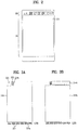
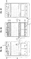
- FIG. 2 and FIG. 3 show a display unit of a mobile terminal according to the present invention.
- the display unit of the present invention may include a plurality of display regions.
- the display unit may include an LCD (liquid crystal display) panel and a backlight unit.
- FIG. 2 is a diagram for one example of a display unit of a mobile terminal according to an example of the present invention.
- FIG. 2 shows an LCD panel of the display unit provided to the mobile terminal according to the present invention.
- the display unit of the present invention can be partitioned into two display regions disposed side by side in a first direction, and more particularly, into a first display region 10 and a second display region 20.
- the mobile terminal can independently control each of the two display regions.
- the first display region 10 may correspond to a main display region and the second display region 20 may correspond to a sub display region.
- the first display region 10 may correspond to a region for outputting general image information and the second display region 20 may correspond to a region for outputting a status bar indicating states of the mobile terminal.
- the first display region 10 may correspond to a region for outputting a running screen of an application and the second display region 20 may correspond to a region for outputting a control screen of the application run on the first display region 10.
- the mobile terminal selectively activates one of the two display regions, thereby reducing power consumption. For instance, while the first display region 10 is in deactivated state and the second display region 20 is in activated state, a user can check a status of the mobile terminal and an event occurring in the mobile terminal through the second display region 20.
- the second display region 20 may be configured in a manner that one of a width and height of the second display region 20 is smaller than that of the first display region 10. And, the second display region 20 may be disposed on one side of the first display region 10. Moreover, the second display region 20 may be formed in a rectangular shape and have a size smaller than that of the first display region 10.
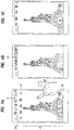
- FIG. 3A and 3B are diagrams for one example of a display unit of a mobile terminal according to an example of the present invention.
- FIG. 3 shows a backlight unit of a display unit provided to a mobile terminal according to the present invention.
- the backlight unit of the mobile terminal may include a light guide plate 310 and light sources 321 and 322.
- the backlight unit of the present invention may include the light sources supplying light in two directions.
- the main light source 321 disposed side by side along a first lateral side 331a of the light guide plate 310 can evenly supply light to the whole light guide plate 310.
- the main light source 321 is spaced apart from the first lateral side 331a.
- a plurality of the main light sources 321 can be provided.
- the sub light source 322 disposed on a second lateral side 331b of the light guide plate 310 can supply light to a side opposite to the first lateral side 331a on which the main light source 321 is disposed.
- the light guide plate 310 may be formed in rectangular shape. Yet, the light guide plate 310 may include a dent 332 recessed concavely from one corner of the light guide plate 310. A lateral side configuring the dent 332, i.e., a lateral side vertical to the first lateral side 331a becomes the second lateral side 331b. And, the light projected from the sub light source 322 is incident on the second lateral side 331b.
- the mobile terminal according to the present invention can independently drive the main light source 321 and the sub light source 322. Hence, the mobile terminal can control the main light source 321 or the sub light source 322 to be turned on only.
- a plurality of the main light sources 321 may be provided adjacent to the first lateral side 331a side by side, thereby supplying light to the whole light guide plate 310. Yet, one or two sub light sources 322 may be provided less than the main light sources 321, thereby supplying light to a portion of the light guide plate 310.
- the light guide plate 310 may be provided to the display unit in a manner of being formed in one body or separated. Referring to FIG. 3 A , the light guide plate 310 is formed in one body, thereby receiving the light supplied by the sub light source 322 as well as the light supplied by the main light source 321. Moreover, if the light guide plate 310 is formed in one body, the mobile terminal can output a connected screen to a first display region and a second display region.
- the light guide plate 310 may be provided in separated form and include a first light guide plate 310a projecting the light supplied by the main light source 321 toward a front surface of the display unit and a second light guide plate 310b projecting the light supplied by the sub light source 322 toward the front surface of the display unit.
- the light of the main light source 321 is supplied to the first display region through the first light guide plate 310a only, while the light of the sub light source 322 is supplied to the second display region through the second light guide plate 310b only.
- a method of displaying an object on a second display region in accordance with a switch mode set in a mobile terminal is described as follows.
- the switch mode set in the mobile terminal may include an auto mode and a manual mode.
- a user can use an object displayed on the second display region.
- FIGs. 4 to 6 show a method of displaying a running screen of an application and an object for controlling the application using the aforementioned first and second display regions.
- FIGs. 4 to 6 correspond to an auto mode in which an object is automatically set to be displayed on the second display region.
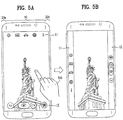
- FIG. 4A, 4B and 4C are diagrams for one example of displaying objects on a first display region and a second display region in a mobile terminal according to an example of the present invention.
- a mobile terminal can display at least one preset object 21 on the second display region 20 no matter whether an application is run or not.
- the mobile terminal can display a preset object 21.
- the preset object may include one of an object indicating a state of the mobile terminal, an object indicating an event occurring in the mobile terminal, an object corresponding to a preset application, and the like.
- the object indicating the state of the mobile terminal may include one of a battery object, a time object, a Wi-Fi object, and the like.
- the object indicating the event occurring in the mobile terminal may include one of a message object, a phone object, an SNS object, and the like.
- the object corresponding to the preset application may correspond to an object indicating one of various applications set by a user.
- the preset object 21 may include a plurality of objects but may not be displayed on the second display region 20 simultaneously. In doing so, if an input signal of scrolling in a left or right direction, the mobile terminal may display an object, which fails to be displayed among a plurality of the objects included in the preset object 21, on the second display region 20.
- the mobile terminal can sense an input signal (not shown in the drawing) for running an application.
- the input signal (not shown in the drawing) may correspond to a signal for selecting an application displayed on a home screen.
- the input signal sensed application is a camera application.
- applications to be run may include a third party application as well as an application autonomously provided to the mobile terminal.
- the mobile terminal can display a running screen of the application on the first display region 10.
- the running screen of the application may correspond to a preview image sensed by the camera.
- the mobile terminal can display at least one or more objects 11 and 12 corresponding to the application on the first display region 10 [Normal view].
- the at least one object corresponding to the application may include a menu icon for controlling the application.
- the object corresponding to the application may correspond to a menu icon for taking an image or video on the camera application.
- the mobile terminal may display a menu icon (not shown in the drawing) for controlling the mobile terminal on the first display region 10 as well as the objects 11 and 12 corresponding to the application.
- the menu icon (not shown in the drawing) for controlling the mobile terminal may include one of a home screen icon, a previous screen icon, a menu icon and the like.
- the mobile terminal can sense an input signal 400 for the first display region 10.
- the input signal 400 may correspond to one of a short touch input and a long touch input.
- the input signal 400 may include one of a drag touch input in continuation with a long touch input and a flicking touch input.
- the mobile terminal can display a preset switch object, which is selected from the at least one or more objects 11 and 12 corresponding to the application, on the second display region 20 in a manner of moving the preset switch object from the first display region 10 to the second display region 20 [Clean view].
- the preset switch object may correspond to all or portion of the at least one or more objects corresponding to the application.
- the mobile terminal in response to the input signal 400, can display all the objects 11 and 12 corresponding to the application on the second display region 20 by moving the objects 11 and 12 from the first display region 10 to the second display region 20.
- the mobile terminal can display the running screen of the application on the first display region 10 only.
- a user can use the running screen of the application as wide as possible.
- a user can recognize an image sensed by the camera as a wider and larger image.
- the mobile terminal in response to the input signal 400, can display a portion of the at least one or more objects 11 and 12 corresponding to the application on the second display region 20 by moving the portion to the second display region 20 from the first display region 10.
- the mobile terminal in response to the input signal 400, may move the first object 11 included in the objects corresponding to the application to the second display region 20 only but may control the second object 12 to be still displayed on the first display region 10.
- the mobile terminal in response to the input signal 400, can remove the preset object 21 displayed on the second display region 20. Yet, if an additional input signal (not shown in the drawing) is sensed, the mobile terminal can re-display the preset object 21 on the second display region 20. This will be described in detail with reference to FIG. 9 later.
- the mobile terminal can adjust the focus on a short touch input sensed position [not shown in FIG. 4 ]. Moreover, if a long touch input to the first display region 10 is sensed, the mobile terminal can capture an image. This is non-limited by the above-described embodiment but can be implemented diversely.
- the mobile terminal can sense an input signal (not shown in the drawing) for the second display region 20 [not shown in FIG. 4 ].
- the input signal may correspond to a drag touch input or a long touch input.
- the mobile terminal in response to the input signal (not shown in the drawing), can display the preset switch object on the first display region 10 again by moving the preset switch object from the second display region 20 to the first display region 10. In doing so, the mobile terminal can re-display at least one preset object 21 on the second display region 20.
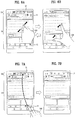
- FIG. 5A and 5B are diagrams for one example of displaying objects on a first display region and a second display region in a mobile terminal according to an example of the present invention. Substance redundant with the former description with reference to FIG. 4 shall be omitted from the following description with reference to FIG. 5 .
- second display regions 20a and 20b may be situated on both sides of a first display region 10 with reference to the time in which the mobile terminal is used in portrait mode, respectively.
- the portrait mode may correspond to a mode used in a state that a length of the display unit of the mobile terminal is greater than a width of the display unit.
- the second display regions 20a and 20b may be situated not on a front side of the mobile terminal but on a lateral side of the mobile terminal.
- the mobile terminal can display a running screen of an application and at least one or more objects 11 and 12 corresponding to the application on the first display region 10 [Normal view]. In doing so, the mobile terminal can sense an input signal 500 for the first display region 10.
- the input signal 500 may include one of a short touch input, a drag touch input, a flicking touch input and the like.
- the mobile terminal in response to the input signal 500, can display the at least one or more objects 11 and 12 on the second display regions 20a and 20b [Clean view]. For instance, the mobile terminal displays the first object 11 on the second display region 20a and is also able to display the second object 12 on the second display region 20b. Yet, the positions for displaying the first and second objects 11 and 12 corresponding to the application are non-limited by this.
- FIG. 6A and 6B are diagrams for one example of displaying objects on a first display region and a second display region in a mobile terminal according to an example of the present invention. Substance redundant with the former description with reference to FIG. 4 shall be omitted from the following description with reference to FIG. 6 .
- the mobile terminal displays a running screen of the application on a first region 10 and is also able to display at least one preset object 21 on a second display region 20. Moreover, the mobile terminal can simultaneously display at least one or more objects 11 and 12 corresponding to the application on the first region 10 together with the running screen of the application.
- the objects 11 and 12 corresponding to the application may correspond to objects maintained constantly despite that the running screen of the application is changed.
- the run application is a search application
- the object 11 corresponding to the application may correspond to a search window
- the object 12 corresponding to the application may include a back icon, a forward icon, a home screen icon, a bookmark icon, and the like.
- the mobile terminal can sense an input signal 610 for the first display region 10.
- the input signal 610 may correspond to a pinch-out touch input.
- the mobile terminal can display a preset object among the objects corresponding to the application, which are displayed on the first display region 10, on the second display region 20 by moving the preset object to the second display region 20.
- the object moved to the second display region 20 may correspond to an object preset by a user or an object preset on the application autonomously.
- the preset object may correspond one of an object occupying a largest region, an object situated on a top end portion, an object situated on a bottom end portion, and the like.
- the mobile terminal in response to the first input signal 610, can display the search window object 11 among the objects corresponding to the application on the second display region 20. Yet, unlike FIG. 6 B, in response to the first input signal 610, the mobile terminal can display the object 12, which corresponds to the menu icon among the objects corresponding to the application, on the second display region 20. Besides, in response to the first input signal 610, the mobile terminal may display all the objects corresponding to the application on the second display region 20 [not shown in FIG. 6 B ].
- the mobile terminal can sense a second input signal 620.
- the second input signal 620 may correspond to a pinch-in touch input.
- the mobile terminal can re-display the object corresponding to the application, which is displayed on the second display region 20, on the first display region 10.
- the mobile terminal can display the preset object 21 on the second display region 20.
- FIG. 7 and FIG. 8 correspond to a manual mode for a user to select an object to display on a second display region.
- FIG. 7A and 7B are diagrams for one example of selecting a portion of objects corresponding to an application and then display the selected portion on a second display region in a mobile terminal according to an example of the present invention.
- the mobile terminal displays a running screen of the application on a first region 10 and is also able to display at least one preset object 21 on a second display region 20.
- the mobile terminal can sense an input signal 700 for the first display region 10.
- the input signal 700 may include one of a drag touch input and a flicking touch input.
- the input signal 700 may correspond to an input ending to the second display region 20 by starting from the first display region 10.
- the region, from which the input signal 700 starts may correspond to a region including an object 11 corresponding to the currently run application in the first display region.
- the mobile terminal in response to the input signal 700, can display the object 11 corresponding to the application on the second display region 20. Moreover, in doing so, in response to the input signal 700, the mobile terminal can remove the preset object 21 previously displayed on the second display region 20.
- the mobile terminal may display the search window object on the second display region 20.
- FIG. 8A, 8B and 8C are diagrams for one example of selecting a portion of objects corresponding to an application and then display the selected portion on a second display region in a mobile terminal according to one embodiment of the present invention.
- the mobile terminal displays a running screen of the application on a first region 10 and is also able to display at least one preset object 21 on a second display region 20.
- the mobile terminal can sense an input signal 810 for the first display region 10.
- the input signal 810 may include a long touch input.
- a position from which the first input signal 810 is sensed may correspond to a region on which such a content as a text, an image or the like is not displayed in the running screen of the application.
- a type of the first input signal 810 or the sensed position of the first input signal 810 may be non-limited by the above description but can include various types of input signals or various sensed positions.
- the mobile terminal can display separate indicators 821 to 824 on the running screen of the application.
- each of the separate indicators 821 to 824 can indicate a region displayable independently by being separated from the running screen of the application.
- a region for displaying each of the separate indicators 821 to 824 may correspond to one of a region having no change in accordance with a use of the application, a region requiring a real-time update, a region including a menu icon necessary for a use of the application, and the like.
- Each of the separate indicators 821 to 824 may include a graphic effect represented in various colors. Through this, a user can recognize an object switchable to the second display region 20 easily and conveniently.
- the mobile terminal can sense a second input signal 830 for the region on which each of the separate indicators 821 to 824 is displayed.
- the second input signal 830 may correspond to a short touch input, by which types of the second input signal 830 may be non-limited.
- the mobile terminal can sense a short touch input to the region 824 on which menu icons required for using the application are displayed.
- the mobile terminal moves the object displayed on the region from which the second input signal 830 is sensed to the second display region 20 and is then able to display the moved object on the second display region 20.
- the mobile terminal can display the menu icon displayed region 824 on the second display region 20.
- the mobile terminal can remove the existing preset object 21 from the second display region 20.
- the menu icon displayed region 824 has moved into the second display region 20, a user can use the running screen of the application on the first display region 10 more widely.
- FIG. 9A, 9B and 9C are diagrams for one example of displaying an object on a second display region in a mobile terminal according to one embodiment of the present invention.
- the mobile terminal displays a running screen of an application on a first display region 10 and is also able to display an object 11 corresponding to the application on a second display region 20. In doing so, the mobile terminal can display a visual cue 50 indicating a presence of a preset object 21.
- the mobile terminal can sense a first input signal 900 for the visual cue 50.
- the first input signal 810 may correspond to a drag or flicking touch input in a bottom direction.
- the mobile terminal in response to the first input signal 900, can display at least one preset object 21 on the second display region 20. For instance, in response to the drag touch input of the first input signal 900, the mobile terminal can display the at least one preset object 21 in a manner of controlling the preset object 21 to slide from a top end to a bottom end of the second display region 20.
- the mobile terminal removes the preset object 21 from the second display region 20 and is able to display the object 11 corresponding to the application on the second display region 20.
- the preset time may correspond to 10 seconds, by which the preset time is non-limited.
- the mobile terminal may sense a second input signal (not shown in the drawing) [not shown in FIG. 9 ].
- the second input signal may correspond to a drag or flicking touch in a direction opposite to that of the first input signal 900 mentioned in the foregoing description. If so, in response to the second input signal (not shown in the drawing), the mobile terminal removes the at least one preset object 21 in a manner of controlling the object 21 to slide in a top direction and is able to display the object 11 corresponding to the application on the second display region 20.
- FIG. 10 is a diagram for a method of controlling a mobile terminal according to an example of the present invention.
- the respective steps described with reference to FIG. 10 in the following can be controlled by the controller of the mobile terminal shown in FIG. 1 .
- the mobile terminal can display at least one preset object on a second display region [S1010]. As mentioned in the foregoing description with reference to FIG. 4 , if the second display region is in an activated state, the mobile terminal can display the at least one preset object on the second display region no matter whether an application is activated or not.
- the mobile terminal can sense a first input signal [S1020]. In doing so, the mobile terminal displays a running screen of the application on a first display region and is also able to display at least one object corresponding to the application. For instance, the at least one object corresponding to the application may correspond to a menu icon for controlling the application.
- the mobile terminal moves the at least one object corresponding to the application into the second display region and is then able to display the moved at least one object on the second display region [S1030]. In doing so, the mobile terminal can remove the at least one preset object displayed on the second display region.
- Various embodiments may be implemented using a machine-readable medium having instructions stored thereon for execution by a processor to perform various methods presented herein.
- Examples of possible machine-readable mediums include HDD(Hard Disk Drive), SSD(Solid State Disk), SDD(Silicon Disk Drive), ROM, RAM, CD-ROM, a magnetic tape, a floppy disk, an optical data storage device, the other types of storage mediums presented herein, and combinations thereof.
- the machine-readable medium may be realized in the form of a carrier wave (for example, a transmission over the Internet).
- the processor may include the controller 180 of the mobile terminal.
Landscapes
- Engineering & Computer Science (AREA)
- Theoretical Computer Science (AREA)
- General Engineering & Computer Science (AREA)
- Human Computer Interaction (AREA)
- Physics & Mathematics (AREA)
- General Physics & Mathematics (AREA)
- Computer Hardware Design (AREA)
- Computer Networks & Wireless Communication (AREA)
- Signal Processing (AREA)
- Business, Economics & Management (AREA)
- General Business, Economics & Management (AREA)
- Telephone Function (AREA)
- User Interface Of Digital Computer (AREA)
Claims (8)
- Mobiles Endgerät (100), mit:einem Display, welches einen ersten Anzeigebereich (10) und einen zweiten Anzeigebereich (20) aufweist,einem Sensor (140), undeiner Steuereinheit (180), die eingerichtet ist zum:Ausführen einer Anwendung und Veranlassen, dass das Display einen Ausführungsbildschirm der ausgeführten Anwendung auf dem ersten Anzeigebereich anzeigt,Veranlassen, dass das Display wenigstens ein Hauptobjekt (11, 12) auf dem ersten Anzeigebereich (10) und wenigstens ein Nebenobjekt (21) auf dem zweiten Anzeigebereich (20) anzeigt,wobei das wenigstens eine Hauptobjekt (11, 12) ein Objekt der ausgeführten Anwendung ist, undwobei das wenigstens eine Nebenobjekt (21) einen Status des mobilen Endgeräts und ein in dem mobilen Endgerät auftretendes Ereignis repräsentiert, undVeranlassen, dass das Display in Reaktion auf eine erste Eingabe (810) einen separaten Indikator (821-824) auf dem wenigstens einen Hauptobjekt anzeigt,Veranlassen, dass das Display in Reaktion auf eine zweite Eingabe (830), die mittels des Sensors empfangen wird, während der Ausführungsbildschirm angezeigt wird, das wenigstens eine Hauptobjekt (11, 12) auf dem zweiten Anzeigebereich (20) anzeigt, wobei die zweite Eingabe (830) auf dem wenigstens einen Hauptobjekt nach der ersten Eingabe (810) empfangen wird, undVeranlassen, dass das Display in Reaktion auf die zweite Eingabe (830) das Anzeigen des wenigstens einen Nebenobjekts (21) beendet.
- Mobiles Endgerät (100) nach Anspruch 1, bei dem die erste Eingabe (810) eine Eingabe auf einen Bereich des ersten Anzeigebereichs (10) umfasst, in dem kein Text oder Bild, der bzw. das die Anwendung betrifft, angezeigt wird.
- Mobiles Endgerät (100) nach Anspruch 1, bei dem die Steuereinheit (180) ferner dazu eingerichtet ist, das Display dazu zu veranlassen, in Reaktion auf die zweite Eingabe (830) einen Objektindikator (50) auf dem zweiten Anzeigebereich (20) anzuzeigen, wobei der Objektindikator die Existenz des wenigstens einen Nebenobjekts (21) anzeigt.
- Mobiles Endgerät (100) nach Anspruch 3, bei dem die Steuereinheit (180) ferner dazu eingerichtet ist, das Display dazu zu veranlassen, in Reaktion auf eine dritte Eingabe auf den Objektindikator das wenigstens eine Nebenobjekt (21) auf dem zweiten Anzeigebereich (20) anzuzeigen.
- Mobiles Endgerät (100) nach Anspruch 4, bei dem die Steuereinheit (180) ferner dazu eingerichtet ist, das Display dazu zu veranlassen, nach einer voreingestellten Schwellenzeitdauer ein Anzeigen des wenigstens einen Nebenobjekts (21) zu beenden.
- Mobiles Endgerät (100) nach einem der vorhergehenden Ansprüche, bei dem der erste Anzeigebereich (10) und der zweite Anzeigebereich (20) Abschnitten eines einzigen Anzeigefelds des mobilen Endgeräts (100) entsprechen.
- Mobiles Endgerät (100) nach einem der vorhergehenden Ansprüche, bei dem das wenigstens eine Hauptobjekt (11, 12) ein Objekt einer Menüoption zum Steuern der ausgeführten Anwendung ist.
- Verfahren zum Steuern eines mobilen Endgeräts (100), welches ein Display mit einem ersten Anzeigebereich (10) und einem zweiten Anzeigebereich (20) aufweist, wobei das Verfahren umfasst:Ausführen einer Anwendung und Anzeigen eines Ausführungsbildschirms der ausgeführten Anwendung auf dem ersten Anzeigebereich,Anzeigen wenigstens eines Hauptobjekts (11, 12) auf dem ersten Anzeigebereich (10) und wenigstens eines Nebenobjekts (21) auf dem zweiten Anzeigebereich (20),wobei das wenigstens eine Hauptobjekt (11, 12) ein Objekt der ausgeführten Anwendung ist, undwobei das wenigstens eine Nebenobjekt (21) einen Status des mobilen Endgeräts und ein in dem mobilen Endgerät auftretendes Ereignis repräsentiert, undAnzeigen eines separaten Indikators (821-824) auf dem wenigstens einen Hauptobjekt in Reaktion auf eine erste Eingabe (810),Anzeigen des wenigstens einen Hauptobjekts (11, 12) auf dem zweiten Anzeigebereich (20) in Reaktion auf eine zweite Eingabe (830), die mittels eines Sensors (140) des mobilen Endgeräts (100) empfangen wird, während der Ausführungsbildschirm angezeigt wird,wobei die zweite Eingabe (830) auf dem wenigstens einen Hauptobjekt nach der ersten Eingabe (810) empfangen wird, undBeenden des Anzeigens des wenigstens einen Nebenobjekts (21) in Reaktion auf die zweite Eingabe (830).
Applications Claiming Priority (1)
| Application Number | Priority Date | Filing Date | Title |
|---|---|---|---|
| KR1020150132190A KR102410212B1 (ko) | 2015-09-18 | 2015-09-18 | 이동 단말기 및 그 제어 방법 |
Publications (2)
| Publication Number | Publication Date |
|---|---|
| EP3144767A1 EP3144767A1 (de) | 2017-03-22 |
| EP3144767B1 true EP3144767B1 (de) | 2020-11-25 |
Family
ID=56684412
Family Applications (1)
| Application Number | Title | Priority Date | Filing Date |
|---|---|---|---|
| EP16001572.3A Active EP3144767B1 (de) | 2015-09-18 | 2016-07-15 | Mobiles endgerät und steuerungsverfahren dafür |
Country Status (4)
| Country | Link |
|---|---|
| US (1) | US10712895B2 (de) |
| EP (1) | EP3144767B1 (de) |
| KR (1) | KR102410212B1 (de) |
| CN (1) | CN107040641A (de) |
Family Cites Families (10)
| Publication number | Priority date | Publication date | Assignee | Title |
|---|---|---|---|---|
| KR100831721B1 (ko) * | 2006-12-29 | 2008-05-22 | 엘지전자 주식회사 | 휴대단말기의 디스플레이 장치 및 방법 |
| US20080229232A1 (en) * | 2007-03-16 | 2008-09-18 | Apple Inc. | Full screen editing of visual media |
| KR20100128958A (ko) | 2009-05-29 | 2010-12-08 | 엘지전자 주식회사 | 영상표시장치 및 그 제어방법 |
| EP2360665A3 (de) * | 2009-11-26 | 2012-03-28 | LG Electronics | Mobiles Endgerät und Steuerungsverfahren dafür |
| WO2012046890A1 (ko) * | 2010-10-06 | 2012-04-12 | 엘지전자 주식회사 | 이동단말기, 디스플레이 장치 및 그 제어 방법 |
| KR101935039B1 (ko) * | 2012-09-11 | 2019-01-03 | 엘지전자 주식회사 | 이동 단말기 및 이동 단말기의 제어 방법 |
| CN103513879B (zh) | 2013-04-26 | 2017-10-24 | 展讯通信(上海)有限公司 | 触控设备及其显示控制方法及装置 |
| WO2014177753A1 (en) * | 2013-04-30 | 2014-11-06 | Multitouch Oy | Dynamic drawers |
| EP2916195B1 (de) * | 2014-03-03 | 2019-09-11 | LG Electronics Inc. | Mobiles Endgerät und Steuerungsverfahren dafür |
| US9467608B2 (en) * | 2015-01-27 | 2016-10-11 | Moment Inc | Auxiliary lens for mobile photography |
-
2015
- 2015-09-18 KR KR1020150132190A patent/KR102410212B1/ko active IP Right Grant
-
2016
- 2016-07-15 EP EP16001572.3A patent/EP3144767B1/de active Active
- 2016-07-22 US US15/217,726 patent/US10712895B2/en active Active
- 2016-09-18 CN CN201610828994.5A patent/CN107040641A/zh active Pending
Non-Patent Citations (1)
| Title |
|---|
| None * |
Also Published As
| Publication number | Publication date |
|---|---|
| KR102410212B1 (ko) | 2022-06-17 |
| EP3144767A1 (de) | 2017-03-22 |
| US10712895B2 (en) | 2020-07-14 |
| US20170083169A1 (en) | 2017-03-23 |
| KR20170034031A (ko) | 2017-03-28 |
| CN107040641A (zh) | 2017-08-11 |
Similar Documents
| Publication | Publication Date | Title |
|---|---|---|
| US10452156B2 (en) | Mobile terminal and control method therefor | |
| US10571929B2 (en) | Mobile terminal and control method therefor | |
| US10331342B2 (en) | Mobile terminal and control method therefor | |
| US20170013179A1 (en) | Mobile terminal and method for controlling the same | |
| US10970092B2 (en) | Terminal with a display including a main display region and a purality of sub display regions and method for controlling the same | |
| US20160080639A1 (en) | Mobile terminal and control method thereof | |
| US10671257B2 (en) | Display apparatus for displaying an image corresponding to a specific region | |
| US10732833B2 (en) | Mobile terminal and method for controlling the same | |
| US10158807B2 (en) | Mobile terminal and method for controlling the same | |
| US9798460B2 (en) | Mobile terminal and method for controlling the same | |
| US10692263B2 (en) | Terminal and method for causing display of a collage wallpaper | |
| US10585555B2 (en) | Mobile terminal and controlling method thereof | |
| EP3276476B1 (de) | Anzeigevorrichtung | |
| EP3264229A1 (de) | Endgerät und steuerungsverfahren dafür | |
| US20200112658A1 (en) | Camera module and mobile terminal having the same | |
| US20190179132A1 (en) | Electronic device having camera device | |
| US10175877B2 (en) | Mobile terminal and method for controlling the same | |
| EP3096462A1 (de) | Mobiles endgerät | |
| US20160335983A1 (en) | Mobile terminal and control method therefor | |
| US20180081534A1 (en) | Mobile terminal and method for controlling the same | |
| US10671992B2 (en) | Terminal and controlling method thereof | |
| EP3267667A2 (de) | Mobiles endgerät und verfahren zur steuerung davon, anzeigevorrichtung und verfahren zur steuerung davon | |
| US10863087B2 (en) | Mobile terminal selecting normal mode or wide angle camera mode based on movement of mobile terminal | |
| EP3144767B1 (de) | Mobiles endgerät und steuerungsverfahren dafür |
Legal Events
| Date | Code | Title | Description |
|---|---|---|---|
| PUAI | Public reference made under article 153(3) epc to a published international application that has entered the european phase |
Free format text: ORIGINAL CODE: 0009012 |
|
| STAA | Information on the status of an ep patent application or granted ep patent |
Free format text: STATUS: THE APPLICATION HAS BEEN PUBLISHED |
|
| AK | Designated contracting states |
Kind code of ref document: A1 Designated state(s): AL AT BE BG CH CY CZ DE DK EE ES FI FR GB GR HR HU IE IS IT LI LT LU LV MC MK MT NL NO PL PT RO RS SE SI SK SM TR |
|
| AX | Request for extension of the european patent |
Extension state: BA ME |
|
| STAA | Information on the status of an ep patent application or granted ep patent |
Free format text: STATUS: REQUEST FOR EXAMINATION WAS MADE |
|
| 17P | Request for examination filed |
Effective date: 20170913 |
|
| STAA | Information on the status of an ep patent application or granted ep patent |
Free format text: STATUS: EXAMINATION IS IN PROGRESS |
|
| 17Q | First examination report despatched |
Effective date: 20190314 |
|
| GRAP | Despatch of communication of intention to grant a patent |
Free format text: ORIGINAL CODE: EPIDOSNIGR1 |
|
| STAA | Information on the status of an ep patent application or granted ep patent |
Free format text: STATUS: GRANT OF PATENT IS INTENDED |
|
| INTG | Intention to grant announced |
Effective date: 20200615 |
|
| GRAS | Grant fee paid |
Free format text: ORIGINAL CODE: EPIDOSNIGR3 |
|
| GRAA | (expected) grant |
Free format text: ORIGINAL CODE: 0009210 |
|
| STAA | Information on the status of an ep patent application or granted ep patent |
Free format text: STATUS: THE PATENT HAS BEEN GRANTED |
|
| REG | Reference to a national code |
Ref country code: DE Ref legal event code: R082 Ref document number: 602016048393 Country of ref document: DE Representative=s name: WUESTHOFF & WUESTHOFF, PATENTANWAELTE PARTG MB, DE |
|
| AK | Designated contracting states |
Kind code of ref document: B1 Designated state(s): AL AT BE BG CH CY CZ DE DK EE ES FI FR GB GR HR HU IE IS IT LI LT LU LV MC MK MT NL NO PL PT RO RS SE SI SK SM TR |
|
| REG | Reference to a national code |
Ref country code: GB Ref legal event code: FG4D |
|
| REG | Reference to a national code |
Ref country code: CH Ref legal event code: EP |
|
| REG | Reference to a national code |
Ref country code: AT Ref legal event code: REF Ref document number: 1339038 Country of ref document: AT Kind code of ref document: T Effective date: 20201215 |
|
| REG | Reference to a national code |
Ref country code: DE Ref legal event code: R096 Ref document number: 602016048393 Country of ref document: DE |
|
| REG | Reference to a national code |
Ref country code: IE Ref legal event code: FG4D |
|
| REG | Reference to a national code |
Ref country code: AT Ref legal event code: MK05 Ref document number: 1339038 Country of ref document: AT Kind code of ref document: T Effective date: 20201125 |
|
| REG | Reference to a national code |
Ref country code: NL Ref legal event code: MP Effective date: 20201125 |
|
| PG25 | Lapsed in a contracting state [announced via postgrant information from national office to epo] |
Ref country code: GR Free format text: LAPSE BECAUSE OF FAILURE TO SUBMIT A TRANSLATION OF THE DESCRIPTION OR TO PAY THE FEE WITHIN THE PRESCRIBED TIME-LIMIT Effective date: 20210226 Ref country code: NO Free format text: LAPSE BECAUSE OF FAILURE TO SUBMIT A TRANSLATION OF THE DESCRIPTION OR TO PAY THE FEE WITHIN THE PRESCRIBED TIME-LIMIT Effective date: 20210225 Ref country code: FI Free format text: LAPSE BECAUSE OF FAILURE TO SUBMIT A TRANSLATION OF THE DESCRIPTION OR TO PAY THE FEE WITHIN THE PRESCRIBED TIME-LIMIT Effective date: 20201125 Ref country code: PT Free format text: LAPSE BECAUSE OF FAILURE TO SUBMIT A TRANSLATION OF THE DESCRIPTION OR TO PAY THE FEE WITHIN THE PRESCRIBED TIME-LIMIT Effective date: 20210325 Ref country code: RS Free format text: LAPSE BECAUSE OF FAILURE TO SUBMIT A TRANSLATION OF THE DESCRIPTION OR TO PAY THE FEE WITHIN THE PRESCRIBED TIME-LIMIT Effective date: 20201125 |
|
| PG25 | Lapsed in a contracting state [announced via postgrant information from national office to epo] |
Ref country code: PL Free format text: LAPSE BECAUSE OF FAILURE TO SUBMIT A TRANSLATION OF THE DESCRIPTION OR TO PAY THE FEE WITHIN THE PRESCRIBED TIME-LIMIT Effective date: 20201125 Ref country code: SE Free format text: LAPSE BECAUSE OF FAILURE TO SUBMIT A TRANSLATION OF THE DESCRIPTION OR TO PAY THE FEE WITHIN THE PRESCRIBED TIME-LIMIT Effective date: 20201125 Ref country code: IS Free format text: LAPSE BECAUSE OF FAILURE TO SUBMIT A TRANSLATION OF THE DESCRIPTION OR TO PAY THE FEE WITHIN THE PRESCRIBED TIME-LIMIT Effective date: 20210325 Ref country code: LV Free format text: LAPSE BECAUSE OF FAILURE TO SUBMIT A TRANSLATION OF THE DESCRIPTION OR TO PAY THE FEE WITHIN THE PRESCRIBED TIME-LIMIT Effective date: 20201125 Ref country code: BG Free format text: LAPSE BECAUSE OF FAILURE TO SUBMIT A TRANSLATION OF THE DESCRIPTION OR TO PAY THE FEE WITHIN THE PRESCRIBED TIME-LIMIT Effective date: 20210225 Ref country code: AT Free format text: LAPSE BECAUSE OF FAILURE TO SUBMIT A TRANSLATION OF THE DESCRIPTION OR TO PAY THE FEE WITHIN THE PRESCRIBED TIME-LIMIT Effective date: 20201125 |
|
| REG | Reference to a national code |
Ref country code: LT Ref legal event code: MG9D |
|
| PG25 | Lapsed in a contracting state [announced via postgrant information from national office to epo] |
Ref country code: HR Free format text: LAPSE BECAUSE OF FAILURE TO SUBMIT A TRANSLATION OF THE DESCRIPTION OR TO PAY THE FEE WITHIN THE PRESCRIBED TIME-LIMIT Effective date: 20201125 |
|
| PG25 | Lapsed in a contracting state [announced via postgrant information from national office to epo] |
Ref country code: EE Free format text: LAPSE BECAUSE OF FAILURE TO SUBMIT A TRANSLATION OF THE DESCRIPTION OR TO PAY THE FEE WITHIN THE PRESCRIBED TIME-LIMIT Effective date: 20201125 Ref country code: CZ Free format text: LAPSE BECAUSE OF FAILURE TO SUBMIT A TRANSLATION OF THE DESCRIPTION OR TO PAY THE FEE WITHIN THE PRESCRIBED TIME-LIMIT Effective date: 20201125 Ref country code: LT Free format text: LAPSE BECAUSE OF FAILURE TO SUBMIT A TRANSLATION OF THE DESCRIPTION OR TO PAY THE FEE WITHIN THE PRESCRIBED TIME-LIMIT Effective date: 20201125 Ref country code: SM Free format text: LAPSE BECAUSE OF FAILURE TO SUBMIT A TRANSLATION OF THE DESCRIPTION OR TO PAY THE FEE WITHIN THE PRESCRIBED TIME-LIMIT Effective date: 20201125 Ref country code: SK Free format text: LAPSE BECAUSE OF FAILURE TO SUBMIT A TRANSLATION OF THE DESCRIPTION OR TO PAY THE FEE WITHIN THE PRESCRIBED TIME-LIMIT Effective date: 20201125 Ref country code: RO Free format text: LAPSE BECAUSE OF FAILURE TO SUBMIT A TRANSLATION OF THE DESCRIPTION OR TO PAY THE FEE WITHIN THE PRESCRIBED TIME-LIMIT Effective date: 20201125 |
|
| PGFP | Annual fee paid to national office [announced via postgrant information from national office to epo] |
Ref country code: FR Payment date: 20210609 Year of fee payment: 6 |
|
| REG | Reference to a national code |
Ref country code: DE Ref legal event code: R097 Ref document number: 602016048393 Country of ref document: DE |
|
| PG25 | Lapsed in a contracting state [announced via postgrant information from national office to epo] |
Ref country code: DK Free format text: LAPSE BECAUSE OF FAILURE TO SUBMIT A TRANSLATION OF THE DESCRIPTION OR TO PAY THE FEE WITHIN THE PRESCRIBED TIME-LIMIT Effective date: 20201125 |
|
| PLBE | No opposition filed within time limit |
Free format text: ORIGINAL CODE: 0009261 |
|
| STAA | Information on the status of an ep patent application or granted ep patent |
Free format text: STATUS: NO OPPOSITION FILED WITHIN TIME LIMIT |
|
| PG25 | Lapsed in a contracting state [announced via postgrant information from national office to epo] |
Ref country code: AL Free format text: LAPSE BECAUSE OF FAILURE TO SUBMIT A TRANSLATION OF THE DESCRIPTION OR TO PAY THE FEE WITHIN THE PRESCRIBED TIME-LIMIT Effective date: 20201125 Ref country code: IT Free format text: LAPSE BECAUSE OF FAILURE TO SUBMIT A TRANSLATION OF THE DESCRIPTION OR TO PAY THE FEE WITHIN THE PRESCRIBED TIME-LIMIT Effective date: 20201125 Ref country code: NL Free format text: LAPSE BECAUSE OF FAILURE TO SUBMIT A TRANSLATION OF THE DESCRIPTION OR TO PAY THE FEE WITHIN THE PRESCRIBED TIME-LIMIT Effective date: 20201125 |
|
| 26N | No opposition filed |
Effective date: 20210826 |
|
| PG25 | Lapsed in a contracting state [announced via postgrant information from national office to epo] |
Ref country code: ES Free format text: LAPSE BECAUSE OF FAILURE TO SUBMIT A TRANSLATION OF THE DESCRIPTION OR TO PAY THE FEE WITHIN THE PRESCRIBED TIME-LIMIT Effective date: 20201125 Ref country code: SI Free format text: LAPSE BECAUSE OF FAILURE TO SUBMIT A TRANSLATION OF THE DESCRIPTION OR TO PAY THE FEE WITHIN THE PRESCRIBED TIME-LIMIT Effective date: 20201125 |
|
| PGFP | Annual fee paid to national office [announced via postgrant information from national office to epo] |
Ref country code: DE Payment date: 20210607 Year of fee payment: 6 |
|
| REG | Reference to a national code |
Ref country code: CH Ref legal event code: PL |
|
| GBPC | Gb: european patent ceased through non-payment of renewal fee |
Effective date: 20210715 |
|
| PG25 | Lapsed in a contracting state [announced via postgrant information from national office to epo] |
Ref country code: MC Free format text: LAPSE BECAUSE OF FAILURE TO SUBMIT A TRANSLATION OF THE DESCRIPTION OR TO PAY THE FEE WITHIN THE PRESCRIBED TIME-LIMIT Effective date: 20201125 |
|
| REG | Reference to a national code |
Ref country code: BE Ref legal event code: MM Effective date: 20210731 |
|
| PG25 | Lapsed in a contracting state [announced via postgrant information from national office to epo] |
Ref country code: LI Free format text: LAPSE BECAUSE OF NON-PAYMENT OF DUE FEES Effective date: 20210731 Ref country code: GB Free format text: LAPSE BECAUSE OF NON-PAYMENT OF DUE FEES Effective date: 20210715 Ref country code: CH Free format text: LAPSE BECAUSE OF NON-PAYMENT OF DUE FEES Effective date: 20210731 |
|
| PG25 | Lapsed in a contracting state [announced via postgrant information from national office to epo] |
Ref country code: IS Free format text: LAPSE BECAUSE OF FAILURE TO SUBMIT A TRANSLATION OF THE DESCRIPTION OR TO PAY THE FEE WITHIN THE PRESCRIBED TIME-LIMIT Effective date: 20210325 Ref country code: LU Free format text: LAPSE BECAUSE OF NON-PAYMENT OF DUE FEES Effective date: 20210715 |
|
| PG25 | Lapsed in a contracting state [announced via postgrant information from national office to epo] |
Ref country code: IE Free format text: LAPSE BECAUSE OF NON-PAYMENT OF DUE FEES Effective date: 20210715 Ref country code: BE Free format text: LAPSE BECAUSE OF NON-PAYMENT OF DUE FEES Effective date: 20210731 |
|
| REG | Reference to a national code |
Ref country code: DE Ref legal event code: R119 Ref document number: 602016048393 Country of ref document: DE |
|
| PG25 | Lapsed in a contracting state [announced via postgrant information from national office to epo] |
Ref country code: FR Free format text: LAPSE BECAUSE OF NON-PAYMENT OF DUE FEES Effective date: 20220731 |
|
| PG25 | Lapsed in a contracting state [announced via postgrant information from national office to epo] |
Ref country code: HU Free format text: LAPSE BECAUSE OF FAILURE TO SUBMIT A TRANSLATION OF THE DESCRIPTION OR TO PAY THE FEE WITHIN THE PRESCRIBED TIME-LIMIT; INVALID AB INITIO Effective date: 20160715 Ref country code: DE Free format text: LAPSE BECAUSE OF NON-PAYMENT OF DUE FEES Effective date: 20230201 |
|
| PG25 | Lapsed in a contracting state [announced via postgrant information from national office to epo] |
Ref country code: CY Free format text: LAPSE BECAUSE OF FAILURE TO SUBMIT A TRANSLATION OF THE DESCRIPTION OR TO PAY THE FEE WITHIN THE PRESCRIBED TIME-LIMIT Effective date: 20201125 |
|
| PG25 | Lapsed in a contracting state [announced via postgrant information from national office to epo] |
Ref country code: MK Free format text: LAPSE BECAUSE OF FAILURE TO SUBMIT A TRANSLATION OF THE DESCRIPTION OR TO PAY THE FEE WITHIN THE PRESCRIBED TIME-LIMIT Effective date: 20201125 |