EP3144753A1 - Control device and control method - Google Patents
Control device and control method Download PDFInfo
- Publication number
- EP3144753A1 EP3144753A1 EP16186082.0A EP16186082A EP3144753A1 EP 3144753 A1 EP3144753 A1 EP 3144753A1 EP 16186082 A EP16186082 A EP 16186082A EP 3144753 A1 EP3144753 A1 EP 3144753A1
- Authority
- EP
- European Patent Office
- Prior art keywords
- output
- module
- signal
- virtual terminal
- interface module
- Prior art date
- Legal status (The legal status is an assumption and is not a legal conclusion. Google has not performed a legal analysis and makes no representation as to the accuracy of the status listed.)
- Granted
Links
Images



Classifications
-
- G—PHYSICS
- G05—CONTROLLING; REGULATING
- G05B—CONTROL OR REGULATING SYSTEMS IN GENERAL; FUNCTIONAL ELEMENTS OF SUCH SYSTEMS; MONITORING OR TESTING ARRANGEMENTS FOR SUCH SYSTEMS OR ELEMENTS
- G05B19/00—Program-control systems
- G05B19/02—Program-control systems electric
- G05B19/04—Program control other than numerical control, i.e. in sequence controllers or logic controllers
- G05B19/048—Monitoring; Safety
-
- G—PHYSICS
- G05—CONTROLLING; REGULATING
- G05B—CONTROL OR REGULATING SYSTEMS IN GENERAL; FUNCTIONAL ELEMENTS OF SUCH SYSTEMS; MONITORING OR TESTING ARRANGEMENTS FOR SUCH SYSTEMS OR ELEMENTS
- G05B19/00—Program-control systems
- G05B19/02—Program-control systems electric
- G05B19/418—Total factory control, i.e. centrally controlling a plurality of machines, e.g. direct or distributed numerical control [DNC], flexible manufacturing systems [FMS], integrated manufacturing systems [IMS] or computer integrated manufacturing [CIM]
- G05B19/4184—Total factory control, i.e. centrally controlling a plurality of machines, e.g. direct or distributed numerical control [DNC], flexible manufacturing systems [FMS], integrated manufacturing systems [IMS] or computer integrated manufacturing [CIM] characterised by fault tolerance, reliability of production system
-
- G—PHYSICS
- G05—CONTROLLING; REGULATING
- G05B—CONTROL OR REGULATING SYSTEMS IN GENERAL; FUNCTIONAL ELEMENTS OF SUCH SYSTEMS; MONITORING OR TESTING ARRANGEMENTS FOR SUCH SYSTEMS OR ELEMENTS
- G05B15/00—Systems controlled by a computer
-
- G—PHYSICS
- G05—CONTROLLING; REGULATING
- G05B—CONTROL OR REGULATING SYSTEMS IN GENERAL; FUNCTIONAL ELEMENTS OF SUCH SYSTEMS; MONITORING OR TESTING ARRANGEMENTS FOR SUCH SYSTEMS OR ELEMENTS
- G05B15/00—Systems controlled by a computer
- G05B15/02—Systems controlled by a computer electric
-
- G—PHYSICS
- G05—CONTROLLING; REGULATING
- G05B—CONTROL OR REGULATING SYSTEMS IN GENERAL; FUNCTIONAL ELEMENTS OF SUCH SYSTEMS; MONITORING OR TESTING ARRANGEMENTS FOR SUCH SYSTEMS OR ELEMENTS
- G05B19/00—Program-control systems
- G05B19/02—Program-control systems electric
- G05B19/04—Program control other than numerical control, i.e. in sequence controllers or logic controllers
- G05B19/042—Program control other than numerical control, i.e. in sequence controllers or logic controllers using digital processors
- G05B19/0423—Input/output
- G05B19/0425—Safety, monitoring
-
- G—PHYSICS
- G05—CONTROLLING; REGULATING
- G05B—CONTROL OR REGULATING SYSTEMS IN GENERAL; FUNCTIONAL ELEMENTS OF SUCH SYSTEMS; MONITORING OR TESTING ARRANGEMENTS FOR SUCH SYSTEMS OR ELEMENTS
- G05B19/00—Program-control systems
- G05B19/02—Program-control systems electric
- G05B19/418—Total factory control, i.e. centrally controlling a plurality of machines, e.g. direct or distributed numerical control [DNC], flexible manufacturing systems [FMS], integrated manufacturing systems [IMS] or computer integrated manufacturing [CIM]
- G05B19/4185—Total factory control, i.e. centrally controlling a plurality of machines, e.g. direct or distributed numerical control [DNC], flexible manufacturing systems [FMS], integrated manufacturing systems [IMS] or computer integrated manufacturing [CIM] characterised by the network communication
- G05B19/41855—Total factory control, i.e. centrally controlling a plurality of machines, e.g. direct or distributed numerical control [DNC], flexible manufacturing systems [FMS], integrated manufacturing systems [IMS] or computer integrated manufacturing [CIM] characterised by the network communication by local area network [LAN], network structure
-
- G—PHYSICS
- G05—CONTROLLING; REGULATING
- G05B—CONTROL OR REGULATING SYSTEMS IN GENERAL; FUNCTIONAL ELEMENTS OF SUCH SYSTEMS; MONITORING OR TESTING ARRANGEMENTS FOR SUCH SYSTEMS OR ELEMENTS
- G05B23/00—Testing or monitoring of control systems or parts thereof
- G05B23/02—Electric testing or monitoring
- G05B23/0205—Electric testing or monitoring by means of a monitoring system capable of detecting and responding to faults
- G05B23/0259—Electric testing or monitoring by means of a monitoring system capable of detecting and responding to faults characterized by the response to fault detection
- G05B23/0267—Fault communication, e.g. human machine interface [HMI]
- G05B23/027—Alarm generation, e.g. communication protocol; Forms of alarm
-
- G—PHYSICS
- G05—CONTROLLING; REGULATING
- G05F—SYSTEMS FOR REGULATING ELECTRIC OR MAGNETIC VARIABLES
- G05F1/00—Automatic systems in which deviations of an electric quantity from one or more predetermined values are detected at the output of the system and fed back to a device within the system to restore the detected quantity to its predetermined value or values, i.e. retroactive systems
- G05F1/66—Regulating electric power
-
- G—PHYSICS
- G08—SIGNALLING
- G08B—SIGNALLING SYSTEMS, e.g. PERSONAL CALLING SYSTEMS; ORDER TELEGRAPHS; ALARM SYSTEMS
- G08B21/00—Alarms responsive to a single specified undesired or abnormal condition and not otherwise provided for
-
- G—PHYSICS
- G08—SIGNALLING
- G08B—SIGNALLING SYSTEMS, e.g. PERSONAL CALLING SYSTEMS; ORDER TELEGRAPHS; ALARM SYSTEMS
- G08B21/00—Alarms responsive to a single specified undesired or abnormal condition and not otherwise provided for
- G08B21/02—Alarms for ensuring the safety of persons
- G08B21/0202—Child monitoring systems using a transmitter-receiver system carried by the parent and the child
- G08B21/0216—Alarm cancellation after generation
-
- G—PHYSICS
- G08—SIGNALLING
- G08B—SIGNALLING SYSTEMS, e.g. PERSONAL CALLING SYSTEMS; ORDER TELEGRAPHS; ALARM SYSTEMS
- G08B25/00—Alarm systems in which the location of the alarm condition is signalled to a central station, e.g. fire or police telegraphic systems
-
- G—PHYSICS
- G05—CONTROLLING; REGULATING
- G05B—CONTROL OR REGULATING SYSTEMS IN GENERAL; FUNCTIONAL ELEMENTS OF SUCH SYSTEMS; MONITORING OR TESTING ARRANGEMENTS FOR SUCH SYSTEMS OR ELEMENTS
- G05B2219/00—Program-control systems
- G05B2219/10—Plc systems
- G05B2219/14—Plc safety
- G05B2219/14005—Alarm
-
- G—PHYSICS
- G05—CONTROLLING; REGULATING
- G05B—CONTROL OR REGULATING SYSTEMS IN GENERAL; FUNCTIONAL ELEMENTS OF SUCH SYSTEMS; MONITORING OR TESTING ARRANGEMENTS FOR SUCH SYSTEMS OR ELEMENTS
- G05B2219/00—Program-control systems
- G05B2219/10—Plc systems
- G05B2219/14—Plc safety
- G05B2219/14116—Safe, emergency shutdown, esd of system
-
- G—PHYSICS
- G05—CONTROLLING; REGULATING
- G05B—CONTROL OR REGULATING SYSTEMS IN GENERAL; FUNCTIONAL ELEMENTS OF SUCH SYSTEMS; MONITORING OR TESTING ARRANGEMENTS FOR SUCH SYSTEMS OR ELEMENTS
- G05B2219/00—Program-control systems
- G05B2219/20—Pc systems
- G05B2219/25—Pc structure of the system
- G05B2219/25232—DCS, distributed control system, decentralised control unit
Definitions
- the disclosure relates to a control device and a control method.
- a process control system In a plant and a factory (hereinafter, called simply "plant” as a generic name of them), a process control system is established, and an advanced automatic operation is implemented.
- the process control system controls various types of state quantity (for example, pressure, temperature, flow quantity) in an industrial process.
- the process control system In order to secure safety and perform an advanced control, the process control system is equipped with a control system such as a distributed control system (DCS) and a safety system such as a safety instrumented system (SIS).
- DCS distributed control system
- SIS safety instrumented system
- field devices for example, a measurement device and a manipulation device
- a control device controlling the field devices are connected to each other through communication means.
- the control device collects measurement data measured by the field devices, and the control device operates (controls) the field devices in accordance with the collected measurement data, in order to control various types of state quantity.
- the safety instrumented system stops the plant certainly in a safe state. Thereby, physical injury and environmental pollution are prevented beforehand, and expensive facilities are protected.
- field devices which detect gas, flame, heat, smoke are prepared, and an alarm is output in accordance with a detection result of the field device.
- a fire detecting system which is equipped with a carbon monoxide detector is disclosed in United States Patent No. 8,354,935 . If a level of the carbon monoxide measured by the carbon monoxide detector exceeds a threshold value, an alarm is output to an alarm panel.
- a control device may include an interface module configured to supply electric power to a field device installed in a plant, an application executer configured to output a reset signal for resetting the field device, and a converter configured to convert the reset signal, which has been output from the application executer, into a format which is suitable for the interface module.
- An aspect of the present invention is to provide a control device and a control method which can achieve an improvement effect by a change of hardware without changing application logic greatly.
- FIG. 1 is a block diagram illustrating a whole configuration of a process control system 1.
- the process control system 1 is equipped with a field device 100, a control device 200, an operation monitoring terminal 300, and an engineering terminal 400.
- the process control system 1 is established in a plant.
- the plant includes an industrial plant such as a chemical industrial plant, a plant managing and controlling a wellhead (for example, a gas field and an oil field), a plant managing and controlling a generation of electric power (for example, water power, fire power, and nuclear power), a plant managing and controlling a power harvesting (for example, solar power and wind power), a plant managing and controlling water supply and sewerage systems, a dam, and so on.
- an industrial plant such as a chemical industrial plant, a plant managing and controlling a wellhead (for example, a gas field and an oil field), a plant managing and controlling a generation of electric power (for example, water power, fire power, and nuclear power), a plant managing and controlling a power harvesting (for example, solar power and wind power), a plant managing and controlling water supply and sewerage systems, a dam, and so on.
- a plant managing and controlling a wellhead for example, a gas field and an oil field
- a plant managing and controlling a generation of electric power for example, water power, fire power
- the field device 100 is such as a sensor device (for example, a flowmeter and a temperature sensor), a valve device (for example, a flow control valve and an on-off valve), an actuator device (for example, a fan and a motor), and other devices installed in the plant.
- the field device 100 is connected to the control device 200.
- the control device 200, the operation monitoring terminal 300, and the engineering terminal 400 are connected to the intranet N1.
- the intranet N1 is a network such as Ethernet (registered trademark).
- the operation monitoring terminal 300 is a device which is operated by a plant operator, and is used for monitoring process.
- the engineering terminal 400 is a device for creating a program which is to be executed by the control device 200.
- the control device 200 is equipped with an application executer 201, a converter 202, and storage 203.
- the storage 203 stores a program (application logic) executed by the application executer 201.
- the application logic is created by the engineering terminal 400.
- the application logic is described in a function block diagram (FBD: Function block Diagram) format by using a graphical user interface.
- the control device 200 downloads, as a program, the application logic created by the engineering terminal 400 into the storage 203.
- the application executer 201 executes the downloaded program, and collects data of measurement value (process value) from the field device 100.
- the application executer 201 calculates an operation amount based on the collected data, transmits a driving signal to another field device, and controls a process.
- the converter 202 converts the signal, which has been output from the application executer 201, into a format which is suitable for an interface module.
- FIG. 2 is a block diagram illustrating operation of the control device 200 and the operation monitoring terminal 300.
- a FGS Fire and Gas System
- the FGS is a system established in order to prevent expansion of an accident which occurs in the plant.
- the field device 100 used for establishing the FGS is a gas detector, a flame detector, a heat detector, and a smoke detector. If an abnormality (smoke, flame, or the like) occurs in the plant, a measurement value of the field device 100 becomes a value (alarm value) which exceeds a predetermined threshold value. Once the measurement value exceeds the threshold value, even if the measurement value is converged to less than the threshold value, the field device 100 continues to output the alarm value. This is for certainly notifying the abnormality which has occurred in the plant.
- the field device 100 is connected to the control device 200 through the line L1.
- the control device 200 receives the alarm value output from the field device 100. Thereafter, the control device 200 transmits, to the operation monitoring terminal 300, an alarm signal S1 representing that an abnormality has been detected in the field device 100.
- the operation monitoring terminal 300 is equipped with a display 310, an input unit 320, and a communicator 330.
- the display 310 is a display device such as a liquid crystal display.
- the input unit 320 is an input device such as a keyboard and a mouse.
- the communicator 330 communicates with the control device 200 through the intranet N1.
- the field device 100 Even if the abnormality factor is resolved, the field device 100 continues to output an alarm value. In order to release the alarm status of the field device 100, it is necessary to reset the field device 100 (power-off and power-on). This is because it is necessary to release the alarm status under the plant operator's intention after the abnormality factor has been resolved and a safety has been confirmed.
- As an operation method for resetting the field device 100 there are a case where two operations (power-off operation and power-on operation) are performed and a case where power-off and power-on are performed by one operation. This is dependent on an application built in the control device 200.
- the display 310 displays contents of the alarm. Thereby, the plant operator can understand a place where the abnormality has occurred in the plant and contents of the abnormality, and can perform countermeasures for resolving the abnormality factor.
- the plant operator If the plant operator confirms that the abnormality factor which is a cause of the alarm has been resolved, the plant operator inputs instructions for resetting the field device 100 by using the input unit 320 of the operation monitoring terminal 300. In accordance with the instructions, the communicator 330 transmits reset instructions S2 to the control device 200. Thus, the reset instructions for the field device 100 can be transmitted from the operation monitoring terminal 300. Thereby, even if a lot of field devices 100 are installed in the plant, efficiency of the plant operator's work can be improved.
- FIG. 3 is a block diagram illustrating a processing performed in the control device 200.
- the control device 200 is equipped with an A/I module 210, application logic (reset logic 250 and safety logic 260), a software module 270, and a D/O module 280.
- the lines L1 and L2 are arranged in a pair.
- the A/I module 210 is an interface module which receives a measurement value (analog input signal) from the field device 100 through the line L1.
- the A/1 module 210 includes a power supply unit 211 which outputs a direct current signal for supplying electric power to the field device 100 through the line L2.
- An operation signal for operating the field device 100 is overlapped on the direct current signal output through the line L2.
- the converter 202 selects and performs the software module 270 which performs D/O to A/I conversion, out of a software module library where two or more software modules are contained.
- the software module library is stored in the storage 203 shown in FIG. 1 .
- a plurality of software modules which convert to other formats is contained in the software module library, in addition to the software module 270 which performs D/O to A/I conversion.
- the A/I module 210 outputs the measurement value, which has been received from the field device 100, to the software module 270.
- the software module 270 includes a virtual A/I terminal 271, a virtual D/O terminal 272, a virtual D/O terminal 273, and a converting module 274.
- the virtual A/I terminal 271, the virtual D/O terminal 272, and the virtual D/O terminal 273 are virtual terminals implemented by software.
- the virtual A/I terminal 271 outputs the measurement value, which has been output from the A/I module 210, to the safety logic 260.
- the safety logic 260 is one of application logics performed by the application executer 201.
- the safety logic 260 is stored in the storage 203 shown in FIG. 1 .
- the application executer 201 reads the safety logic 260 out of the storage 203 and performs the safety logic 260.
- the safety logic 260 includes a virtual A/I terminal 261, a function block 262, and a virtual D/O terminal 263.
- the virtual A/I terminal 261 and the virtual D/O terminal 263 are virtual terminals implemented by software.
- the measurement value which has been output from the virtual A/I terminal 271 of the software module 270, is input into the virtual A/I terminal 261.
- the function block 262 of the safety logic 260 transmits the measurement value, which has been input into the virtual A/I terminal 261, to the operation monitoring terminal 300 through the intranet N1. If the operation monitoring terminal 300 has received the measurement value of the field device 100, the operation monitoring terminal 300 displays the measurement value (process value) on the display 310 shown in FIG. 2 . Thereby, the plant operator can understand a state of each field device 100 in the plant.
- the function block 262 transmits the alarm signal S1 to the operation monitoring terminal 300. If the operation monitoring terminal 300 has received the alarm signal S1, the operation monitoring terminal 300 displays contents of the alarm on the display 310.
- the plant operator If the plant operator confirms that the abnormality factor which is a cause of the alarm has been resolved, the plant operator inputs instructions for resetting the field device 100 by using the input unit 320 of the operation monitoring terminal 300. In accordance with the instructions, the communicator 330 transmits reset instructions S2 to the control device 200.
- the reset logic 250 is one of application logics performed by the application executer 201.
- the reset logic 250 is stored in the storage 203 shown in FIG. 1 .
- the application executer 201 reads the reset logic 250 out of the storage 203 and performs the reset logic 250.
- the reset logic 250, the safety logic 260, and the software module 270 may be stored in separate storage units respectively.
- the reset logic 250 includes a function block 251 and a virtual D/O terminal 252.
- the virtual D/O terminal 252 is a virtual terminal implemented by software.
- the function block 251 of the reset logic 250 If the function block 251 of the reset logic 250 has received the reset instructions S2 from the operation monitoring terminal 300, the function block 251 generates a reset signal for turning off and turning on a power source of the field device 100.
- the virtual D/O terminal 252 outputs, to the software module 270, the reset signal (digital output signal) which has been generated by the function block 251.
- the reset signal which has been output from the virtual D/O terminal 252 of the reset logic 250, is input into the virtual D/O terminal 272 of the software module 270.
- the converting module 274 converts the reset signal, which has been input into the virtual D/O terminal 272, into a format which is suitable for the A/I module 210. That is, the converting module 274 performs D/O to A/I conversion with respect to the reset signal which has been input into the virtual D/O terminal 272.
- the converting module 274 outputs the converted reset signal S3 to the A/I module 210.
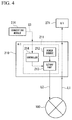
- FIG. 4 is a block diagram illustrating a detailed configuration of the A/I module 210.
- a power supply unit 211 of the A/I module 210 includes a power source 212, the cutoff part 213, and the controller 214.
- the power source 212 supplies electric power to the field device 100.
- the cutoff part 213 is a switch which cuts off the electric power supplied from the power source 212 to the field device 100.
- the controller 214 transmits an operation signal to the field device 100, and performs ON/OFF control of the cutoff part 213.
- the controller 214 turns off the switch of the cutoff part 213 in order to cut off the electric power suppled from the power source 212 to the field device 100. After the power source of the field device 100 was turned off, the controller 214 turns on the switch of the cutoff part 213 in order to restart to supply electric power from the power source 212 to the field device 100. Thereby, the field device 100 can be reset, and the alarm status can be released.
- the function block 262 of the safety logic 260 generates a driving signal for driving an alarm device or a shutoff device 500.
- the case where the measurement value of the field device 100 represents an abnormal value is a case where the measurement value of the field device 100 exceeds a predetermined threshold value.
- the virtual D/O terminal 263 outputs the driving signal (digital output signal), which has been generated by the function block 262, to the software module 270.
- the driving signal which has been output from the virtual D/O terminal 263 of the safety logic 260, is input into the virtual D/O terminal 273 of the software module 270.
- the software module 270 outputs the driving signal, which has been input into the virtual D/O terminal 273, to the D/O module 280.
- the D/O module 280 transmits the driving signal, which has been output from the software module 270, to the alarm device or the shutoff device 500 through the line L4.
- the alarm device 500 is a device for notifying an abnormality by using a siren or a red light.
- the shutoff device 500 is a device for stopping a process forcibly, such as a shutter.
- the alarm device 500 sounds a siren or turns on a red light in accordance with the driving signal which has been received from the D/O module 280. Thereby, danger can be notified to a worker in the plant.
- the shutoff device 500 closes a shutter installed in the plant in accordance with the driving signal which has been received from the D/O module 280. Thereby, flame, smoke, or the like can be prevented from spreading in the plant.
- the alarm device or the shutoff device 500 may cut off electric power of each device in the plant forcibly, and may drive a sprinkler in order to extinguish the fire. Thereby, the damage in the plant can be avoided from expanding.
- FIG. 5 is a block diagram illustrating a whole configuration of a process control system 2 which is a comparison example. A difference between the process control system 1 of the present embodiment and the process control system 2 of the comparison example, and a superiority of the process control system 1 of the present embodiment will be described by using FIG. 5 .
- a relay 600 is prepared between the A/I module 210 and the field device 100, and a D/O module 290 is prepared between the reset logic 250 and the relay 600.
- the software module 270 shown in FIG. 3 does not exist in the process control system 2 of the comparison example.
- the reset logic 250 outputs, from the virtual D/O terminal 252, the reset signal for cutting off the electric power supplied from the power supply unit 211 to the field device 100.
- the reset signal output from the virtual D/O terminal 252 is a signal of which format is suitable for the D/O module 290.
- the D/O module 290 transmits a power-off signal to the relay 600 through the line L3 based on the reset signal output from the virtual D/O terminal 252.
- the relay 600 cuts off the communication and the power supply in the line L1 and the line L2 in accordance with the power-off signal received from the D/O module 290.
- the D/O module 290 transmits a power-on signal to the relay 600 through the line L3.
- the relay 600 restarts the communication and the power supply in the line L1 and the line L2 in accordance with the power-on signal received from the D/O module 290. Thereby, the reset operation is completed.
- the process control system 1 of the present embodiment includes the converter 202 which converts the signal, which has been output from the reset logic 250, into a format which is suitable for the A/I module 210.
- the converter 202 which converts the signal, which has been output from the reset logic 250, into a format which is suitable for the A/I module 210.
- reset instructions are output as a process output to the field device 100.
- the reset instructions are output to the A/I module 210 so that the A/I module 210 can directly switch the internal electric supply.
- the reset instructions are not output to the field device 100 as a process output, but the reset instructions are output to a part of system (A/I module 210).
- the proved application logic (reset logic 250 and safety logic 260) of the conventional system can be diverted as much as possible, and the reset instructions to the system can be performed as a process output which is the same as the comparison example.
- the input signal (the measurement value of the field device 100) to the safety logic 260 is input into the virtual A/I terminal 261, and the output signal (reset signal) from the reset logic 250 is output from the virtual D/O terminal 252.
- the virtual D/O terminal 252 of the reset logic 250 is connected to the virtual D/O terminal 272 of the software module 270.
- the converting module 274 performs D/O to A/I conversion with respect to the signal input into the virtual D/O terminal 272.
- an input/output separation rule about AI input and DO output can be followed strictly in the reset logic 250 and the safety logic 260, and input/output can be performed with respect to the A/I module 210 in actual hardware.
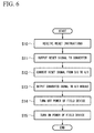
- FIG. 6 is a flow chart illustrating a processing of the control device 200. If the application executer 201 has received the reset instructions S2 transmitted from the operation monitoring terminal 300 (Step S10), the application executer 201 outputs, to the converter 202, the reset signal for turning off and turning on the power source of the field device 100 (Step S11). Specifically, the application executer 201 generates the reset signal by using the function block 251, and outputs the generated reset signal from the virtual D/O terminal 252 to the software module 270.
- the converter 202 performs D/O to A/I conversion with respect to the reset signal output from the application executer 201 (Step S12). Specifically, the converter 202 performs D/O to A/I conversion with respect to the reset signal input into the virtual D/O terminal 272 by using the converting module 274.
- the converter 202 outputs the converted reset signal to the A/I module 210 (Step S13).
- the A/I module 210 turns off the power source of the field device 100 based on the reset signal output from the converter 202 (Step S14).
- the controller 214 prepared in the A/I module 210 turns off the switch of the cutoff part 213 in order to cut off the power supply from the power source 212 to the field device 100.
- the controller 214 turns on the power source of the field device 100 (Step S15). Specifically, the controller 214 turns on the switch of the cutoff part 213 in order to restart to supply electric power from the power source 212 to the field device 100 and transmit the operation signal from the controller 214 to the field device 100. Thereby, the field device 100 can be reset and the alarm status can be released.
- control device 200 of the present embodiment includes the converter 202 which converts the reset signal output from the application executer 201 into a format which is suitable for the A/I module 210.
- the converter 202 which converts the reset signal output from the application executer 201 into a format which is suitable for the A/I module 210.
- the converting module 274 converts the signal, which has been output from the reset logic 250, into a format which is suitable for the A/I module 210 and outputs the converted signal, it is not limited thereto.
- the converting module 274 may convert the signal, which has been input from one or more interface modules (for example, A/I module 210), into a format which is suitable for the application logic (for example, the reset logic 250 or the safety logic 260), and may output the converted signal.
- the software module 270 of the present embodiment includes the converting module 274.
- the converting module 274 converts the signal, which has been output from the application logic (for example, the reset logic 250 or the safety logic 260), into a format which is suitable for an interface module (for example, the A/I module 210), and outputs the converted signal, and/or the converting module 274 converts the signal, which has been input from the interface module, into a format which is suitable for the application logic.
- the term "configured” is used to describe a component, unit or part of a device includes hardware and/or software that is constructed and/or programmed to carry out the desired function.
- unit is used to describe a component, unit or part of a hardware and/or software that is constructed and/or programmed to carry out the desired function.
- Typical examples of the hardware may include, but are not limited to, a device and a circuit.
Landscapes
- Engineering & Computer Science (AREA)
- Physics & Mathematics (AREA)
- General Physics & Mathematics (AREA)
- Automation & Control Theory (AREA)
- General Engineering & Computer Science (AREA)
- Emergency Management (AREA)
- Business, Economics & Management (AREA)
- Radar, Positioning & Navigation (AREA)
- Electromagnetism (AREA)
- Power Engineering (AREA)
- Manufacturing & Machinery (AREA)
- Quality & Reliability (AREA)
- Human Computer Interaction (AREA)
- Health & Medical Sciences (AREA)
- Child & Adolescent Psychology (AREA)
- General Health & Medical Sciences (AREA)
- Programmable Controllers (AREA)
- Safety Devices In Control Systems (AREA)
Description
- The disclosure relates to a control device and a control method.
- Priority is claimed on Japanese Patent Application No.
2015-185017, filed September 18, 2015 - In a plant and a factory (hereinafter, called simply "plant" as a generic name of them), a process control system is established, and an advanced automatic operation is implemented. The process control system controls various types of state quantity (for example, pressure, temperature, flow quantity) in an industrial process. In order to secure safety and perform an advanced control, the process control system is equipped with a control system such as a distributed control system (DCS) and a safety system such as a safety instrumented system (SIS).
- In the distributed control system, field devices (for example, a measurement device and a manipulation device) and a control device controlling the field devices are connected to each other through communication means. In the distributed control system, the control device collects measurement data measured by the field devices, and the control device operates (controls) the field devices in accordance with the collected measurement data, in order to control various types of state quantity. In an emergency, the safety instrumented system stops the plant certainly in a safe state. Thereby, physical injury and environmental pollution are prevented beforehand, and expensive facilities are protected.
- In the conventional safety instrumented system, field devices which detect gas, flame, heat, smoke are prepared, and an alarm is output in accordance with a detection result of the field device. For example, a fire detecting system which is equipped with a carbon monoxide detector is disclosed in United States Patent No.
8,354,935 . If a level of the carbon monoxide measured by the carbon monoxide detector exceeds a threshold value, an alarm is output to an alarm panel. - High reliance and stable operation are required for the distributed control system and the safety instrumented system in order to secure safety of the plant. Therefore, high reliability and high maintainability are required for a program (application logic) which runs on the control device. For this reason, it is not preferable that proven application logic is changed greatly. In some industries or companies, a rule (policy) of programing is often made formally or implicitly.
- On the other hand, with respect to hardware such as an interface module and a field device, new parts are adopted in accordance with technical progress, parts are discontinued, and parts are changed in accordance with cost reduction demands, in many cases. For this reason, in the conventional control device, it is necessary that the application logic is changed greatly in accordance with a change of hardware. Otherwise, it is necessary that a part of an improvement effect by the change of the hardware is given up, and a change range of the application logic is reduced.
- A control device may include an interface module configured to supply electric power to a field device installed in a plant, an application executer configured to output a reset signal for resetting the field device, and a converter configured to convert the reset signal, which has been output from the application executer, into a format which is suitable for the interface module.
- Further features and aspects of the present disclosure will become apparent from the following detailed description of exemplary embodiments with reference to the attached drawings.
-
-
FIG. 1 is a block diagram illustrating a whole configuration of aprocess control system 1. -
FIG. 2 is a block diagram illustrating operation of thecontrol device 200 and theoperation monitoring terminal 300. -
FIG. 3 is a block diagram illustrating a processing performed in thecontrol device 200. -
FIG. 4 is a block diagram illustrating a detailed configuration of the A/I module 210. -
FIG. 5 is a block diagram illustrating a whole configuration of aprocess control system 2 which is a comparison example. -
FIG. 6 is a flow chart illustrating a processing of thecontrol device 200. - The embodiments of the present invention will be now described herein with reference to illustrative preferred embodiments. Those skilled in the art will recognize that many alternative preferred embodiments can be accomplished using the teaching of the present invention and that the present invention is not limited to the preferred embodiments illustrated herein for explanatory purposes.
- An aspect of the present invention is to provide a control device and a control method which can achieve an improvement effect by a change of hardware without changing application logic greatly.
- Hereinafter, a control device and a control method of embodiments will be described with reference to drawings.
-
FIG. 1 is a block diagram illustrating a whole configuration of aprocess control system 1. As shown inFIG. 1 , theprocess control system 1 is equipped with afield device 100, acontrol device 200, anoperation monitoring terminal 300, and anengineering terminal 400. Theprocess control system 1 is established in a plant. - The plant includes an industrial plant such as a chemical industrial plant, a plant managing and controlling a wellhead (for example, a gas field and an oil field), a plant managing and controlling a generation of electric power (for example, water power, fire power, and nuclear power), a plant managing and controlling a power harvesting (for example, solar power and wind power), a plant managing and controlling water supply and sewerage systems, a dam, and so on.
- The
field device 100 is such as a sensor device (for example, a flowmeter and a temperature sensor), a valve device (for example, a flow control valve and an on-off valve), an actuator device (for example, a fan and a motor), and other devices installed in the plant. Thefield device 100 is connected to thecontrol device 200. - The
control device 200, theoperation monitoring terminal 300, and theengineering terminal 400 are connected to the intranet N1. The intranet N1 is a network such as Ethernet (registered trademark). For example, theoperation monitoring terminal 300 is a device which is operated by a plant operator, and is used for monitoring process. Theengineering terminal 400 is a device for creating a program which is to be executed by thecontrol device 200. - The
control device 200 is equipped with anapplication executer 201, aconverter 202, andstorage 203. Thestorage 203 stores a program (application logic) executed by theapplication executer 201. The application logic is created by theengineering terminal 400. For example, the application logic is described in a function block diagram (FBD: Function block Diagram) format by using a graphical user interface. Thecontrol device 200 downloads, as a program, the application logic created by theengineering terminal 400 into thestorage 203. - The
application executer 201 executes the downloaded program, and collects data of measurement value (process value) from thefield device 100. Theapplication executer 201 calculates an operation amount based on the collected data, transmits a driving signal to another field device, and controls a process. Although details will be described later, theconverter 202 converts the signal, which has been output from theapplication executer 201, into a format which is suitable for an interface module. -
FIG. 2 is a block diagram illustrating operation of thecontrol device 200 and theoperation monitoring terminal 300. Hereinafter, a FGS (Fire and Gas System) will be described as an example of a safety instrumented system. - The FGS is a system established in order to prevent expansion of an accident which occurs in the plant. For example, the
field device 100 used for establishing the FGS is a gas detector, a flame detector, a heat detector, and a smoke detector. If an abnormality (smoke, flame, or the like) occurs in the plant, a measurement value of thefield device 100 becomes a value (alarm value) which exceeds a predetermined threshold value. Once the measurement value exceeds the threshold value, even if the measurement value is converged to less than the threshold value, thefield device 100 continues to output the alarm value. This is for certainly notifying the abnormality which has occurred in the plant. - As shown in
FIG. 2 , thefield device 100 is connected to thecontrol device 200 through the line L1. Thecontrol device 200 receives the alarm value output from thefield device 100. Thereafter, thecontrol device 200 transmits, to theoperation monitoring terminal 300, an alarm signal S1 representing that an abnormality has been detected in thefield device 100. - The
operation monitoring terminal 300 is equipped with adisplay 310, aninput unit 320, and acommunicator 330. Thedisplay 310 is a display device such as a liquid crystal display. Theinput unit 320 is an input device such as a keyboard and a mouse. Thecommunicator 330 communicates with thecontrol device 200 through the intranet N1. - Even if the abnormality factor is resolved, the
field device 100 continues to output an alarm value. In order to release the alarm status of thefield device 100, it is necessary to reset the field device 100 (power-off and power-on). This is because it is necessary to release the alarm status under the plant operator's intention after the abnormality factor has been resolved and a safety has been confirmed. As an operation method for resetting thefield device 100, there are a case where two operations (power-off operation and power-on operation) are performed and a case where power-off and power-on are performed by one operation. This is dependent on an application built in thecontrol device 200. - If the
communicator 330 receives the alarm signal S1 from thecontrol device 200, thedisplay 310 displays contents of the alarm. Thereby, the plant operator can understand a place where the abnormality has occurred in the plant and contents of the abnormality, and can perform countermeasures for resolving the abnormality factor. - If the plant operator confirms that the abnormality factor which is a cause of the alarm has been resolved, the plant operator inputs instructions for resetting the
field device 100 by using theinput unit 320 of theoperation monitoring terminal 300. In accordance with the instructions, thecommunicator 330 transmits reset instructions S2 to thecontrol device 200. Thus, the reset instructions for thefield device 100 can be transmitted from theoperation monitoring terminal 300. Thereby, even if a lot offield devices 100 are installed in the plant, efficiency of the plant operator's work can be improved. -
FIG. 3 is a block diagram illustrating a processing performed in thecontrol device 200. Thecontrol device 200 is equipped with an A/I module 210, application logic (resetlogic 250 and safety logic 260), asoftware module 270, and a D/O module 280. - The lines L1 and L2 are arranged in a pair. The A/
I module 210 is an interface module which receives a measurement value (analog input signal) from thefield device 100 through the line L1. The A/1module 210 includes apower supply unit 211 which outputs a direct current signal for supplying electric power to thefield device 100 through the line L2. An operation signal for operating thefield device 100 is overlapped on the direct current signal output through the line L2. - The
converter 202 selects and performs thesoftware module 270 which performs D/O to A/I conversion, out of a software module library where two or more software modules are contained. The software module library is stored in thestorage 203 shown inFIG. 1 . A plurality of software modules which convert to other formats is contained in the software module library, in addition to thesoftware module 270 which performs D/O to A/I conversion. - The A/
I module 210 outputs the measurement value, which has been received from thefield device 100, to thesoftware module 270. Thesoftware module 270 includes a virtual A/I terminal 271, a virtual D/O terminal 272, a virtual D/O terminal 273, and a convertingmodule 274. The virtual A/I terminal 271, the virtual D/O terminal 272, and the virtual D/O terminal 273 are virtual terminals implemented by software. The virtual A/I terminal 271 outputs the measurement value, which has been output from the A/I module 210, to thesafety logic 260. - The
safety logic 260 is one of application logics performed by theapplication executer 201. Thesafety logic 260 is stored in thestorage 203 shown inFIG. 1 . Theapplication executer 201 reads thesafety logic 260 out of thestorage 203 and performs thesafety logic 260. Thesafety logic 260 includes a virtual A/I terminal 261, afunction block 262, and a virtual D/O terminal 263. The virtual A/I terminal 261 and the virtual D/O terminal 263 are virtual terminals implemented by software. The measurement value, which has been output from the virtual A/I terminal 271 of thesoftware module 270, is input into the virtual A/I terminal 261. - The
function block 262 of thesafety logic 260 transmits the measurement value, which has been input into the virtual A/I terminal 261, to the operation monitoring terminal 300 through the intranet N1. If theoperation monitoring terminal 300 has received the measurement value of thefield device 100, the operation monitoring terminal 300 displays the measurement value (process value) on thedisplay 310 shown inFIG. 2 . Thereby, the plant operator can understand a state of eachfield device 100 in the plant. - If an alarm value is transmitted from the
field device 100, thefunction block 262 transmits the alarm signal S1 to theoperation monitoring terminal 300. If theoperation monitoring terminal 300 has received the alarm signal S1, the operation monitoring terminal 300 displays contents of the alarm on thedisplay 310. - If the plant operator confirms that the abnormality factor which is a cause of the alarm has been resolved, the plant operator inputs instructions for resetting the
field device 100 by using theinput unit 320 of theoperation monitoring terminal 300. In accordance with the instructions, thecommunicator 330 transmits reset instructions S2 to thecontrol device 200. - The
reset logic 250 is one of application logics performed by theapplication executer 201. Thereset logic 250 is stored in thestorage 203 shown inFIG. 1 . Theapplication executer 201 reads thereset logic 250 out of thestorage 203 and performs thereset logic 250. Thereset logic 250, thesafety logic 260, and thesoftware module 270 may be stored in separate storage units respectively. Thereset logic 250 includes afunction block 251 and a virtual D/O terminal 252. The virtual D/O terminal 252 is a virtual terminal implemented by software. - If the
function block 251 of thereset logic 250 has received the reset instructions S2 from theoperation monitoring terminal 300, thefunction block 251 generates a reset signal for turning off and turning on a power source of thefield device 100. The virtual D/O terminal 252 outputs, to thesoftware module 270, the reset signal (digital output signal) which has been generated by thefunction block 251. - The reset signal, which has been output from the virtual D/
O terminal 252 of thereset logic 250, is input into the virtual D/O terminal 272 of thesoftware module 270. The convertingmodule 274 converts the reset signal, which has been input into the virtual D/O terminal 272, into a format which is suitable for the A/I module 210. That is, the convertingmodule 274 performs D/O to A/I conversion with respect to the reset signal which has been input into the virtual D/O terminal 272. The convertingmodule 274 outputs the converted reset signal S3 to the A/I module 210. -
FIG. 4 is a block diagram illustrating a detailed configuration of the A/I module 210. Apower supply unit 211 of the A/I module 210 includes apower source 212, thecutoff part 213, and thecontroller 214. Thepower source 212 supplies electric power to thefield device 100. Thecutoff part 213 is a switch which cuts off the electric power supplied from thepower source 212 to thefield device 100. Thecontroller 214 transmits an operation signal to thefield device 100, and performs ON/OFF control of thecutoff part 213. - If the reset signal S3 which has been output from the converting
module 274 is input into thecontroller 214, thecontroller 214 turns off the switch of thecutoff part 213 in order to cut off the electric power suppled from thepower source 212 to thefield device 100. After the power source of thefield device 100 was turned off, thecontroller 214 turns on the switch of thecutoff part 213 in order to restart to supply electric power from thepower source 212 to thefield device 100. Thereby, thefield device 100 can be reset, and the alarm status can be released. - On the other hand if the measurement value of the
field device 100 input into the virtual A/I terminal 261 represents an abnormal value, thefunction block 262 of thesafety logic 260 generates a driving signal for driving an alarm device or ashutoff device 500. For example, the case where the measurement value of thefield device 100 represents an abnormal value is a case where the measurement value of thefield device 100 exceeds a predetermined threshold value. The virtual D/O terminal 263 outputs the driving signal (digital output signal), which has been generated by thefunction block 262, to thesoftware module 270. - The driving signal, which has been output from the virtual D/
O terminal 263 of thesafety logic 260, is input into the virtual D/O terminal 273 of thesoftware module 270. Thesoftware module 270 outputs the driving signal, which has been input into the virtual D/O terminal 273, to the D/O module 280. The D/O module 280 transmits the driving signal, which has been output from thesoftware module 270, to the alarm device or theshutoff device 500 through the line L4. Thealarm device 500 is a device for notifying an abnormality by using a siren or a red light. Theshutoff device 500 is a device for stopping a process forcibly, such as a shutter. - If the measurement value of the
field device 100 represents an abnormal value, flame, smoke, or the like has occurred around thefield device 100. Therefore, thealarm device 500 sounds a siren or turns on a red light in accordance with the driving signal which has been received from the D/O module 280. Thereby, danger can be notified to a worker in the plant. Theshutoff device 500 closes a shutter installed in the plant in accordance with the driving signal which has been received from the D/O module 280. Thereby, flame, smoke, or the like can be prevented from spreading in the plant. In addition, the alarm device or theshutoff device 500 may cut off electric power of each device in the plant forcibly, and may drive a sprinkler in order to extinguish the fire. Thereby, the damage in the plant can be avoided from expanding. -
FIG. 5 is a block diagram illustrating a whole configuration of aprocess control system 2 which is a comparison example. A difference between theprocess control system 1 of the present embodiment and theprocess control system 2 of the comparison example, and a superiority of theprocess control system 1 of the present embodiment will be described by usingFIG. 5 . - As shown in
FIG. 5 , in theprocess control system 2 of the comparison example, arelay 600 is prepared between the A/I module 210 and thefield device 100, and a D/O module 290 is prepared between thereset logic 250 and therelay 600. Thesoftware module 270 shown inFIG. 3 does not exist in theprocess control system 2 of the comparison example. - In the
process control system 2 of the comparison example, thereset logic 250 outputs, from the virtual D/O terminal 252, the reset signal for cutting off the electric power supplied from thepower supply unit 211 to thefield device 100. The reset signal output from the virtual D/O terminal 252 is a signal of which format is suitable for the D/O module 290. - The D/
O module 290 transmits a power-off signal to therelay 600 through the line L3 based on the reset signal output from the virtual D/O terminal 252. Therelay 600 cuts off the communication and the power supply in the line L1 and the line L2 in accordance with the power-off signal received from the D/O module 290. After the power supply to thefield device 100 was turned off, the D/O module 290 transmits a power-on signal to therelay 600 through the line L3. Therelay 600 restarts the communication and the power supply in the line L1 and the line L2 in accordance with the power-on signal received from the D/O module 290. Thereby, the reset operation is completed. - In comparison with the
process control system 2 of the comparison example, since theprocess control system 1 of the present embodiment does not need therelay 600, the D/O module 290, and the line L3, manufacturing costs can be reduced. - In the
process control system 2 of the comparison example, if hardware configuration is changed, it is necessary to greatly change the program (reset logic 250) which runs on thecontrol device 200. However, since high reliability and high maintainability are required for thereset logic 250, it is not preferable that theproven reset logic 250 is changed greatly. - On the other hand, the
process control system 1 of the present embodiment includes theconverter 202 which converts the signal, which has been output from thereset logic 250, into a format which is suitable for the A/I module 210. Thereby, hardware configuration can be changed without changing thereset logic 250 greatly. - In the system of the comparison example, reset instructions are output as a process output to the
field device 100. On the other hand, in the present embodiment, in order to reduce costs of hardware, the reset instructions are output to the A/I module 210 so that the A/I module 210 can directly switch the internal electric supply. - That is, in the present embodiment, the reset instructions are not output to the
field device 100 as a process output, but the reset instructions are output to a part of system (A/I module 210). In the present embodiment, although an output destination of the reset instructions is changed in accordance with the change of hardware, the proved application logic (resetlogic 250 and safety logic 260) of the conventional system can be diverted as much as possible, and the reset instructions to the system can be performed as a process output which is the same as the comparison example. - In the
reset logic 250 and thesafety logic 260, it is required that input and output are separated clearly from viewpoints of visibility and maintainability. In the present embodiment, the input signal (the measurement value of the field device 100) to thesafety logic 260 is input into the virtual A/I terminal 261, and the output signal (reset signal) from thereset logic 250 is output from the virtual D/O terminal 252. - On the other hand, in the configuration of
FIG. 3 , if thesoftware module 270 does not exist, since the D/O module 290 does not exist, both the virtual A/I terminal 261 and the virtual D/O terminal 252 are connected to the A/I module 210. Therefore, input and output are performed with respect to the A/I module 210. In order to improve visibility and maintainability, it is easy-to-understand and desirable that each of the input terminals and the output terminals in thereset logic 250 and thesafety logic 260 have a single function/meaning to become one-to-one. However, the input/output allocation to the A/I module 210 is contrary to this. - Therefore, in the present embodiment, the virtual D/
O terminal 252 of thereset logic 250 is connected to the virtual D/O terminal 272 of thesoftware module 270. The convertingmodule 274 performs D/O to A/I conversion with respect to the signal input into the virtual D/O terminal 272. Thereby, an input/output separation rule about AI input and DO output can be followed strictly in thereset logic 250 and thesafety logic 260, and input/output can be performed with respect to the A/I module 210 in actual hardware. -
FIG. 6 is a flow chart illustrating a processing of thecontrol device 200. If theapplication executer 201 has received the reset instructions S2 transmitted from the operation monitoring terminal 300 (Step S10), theapplication executer 201 outputs, to theconverter 202, the reset signal for turning off and turning on the power source of the field device 100 (Step S11). Specifically, theapplication executer 201 generates the reset signal by using thefunction block 251, and outputs the generated reset signal from the virtual D/O terminal 252 to thesoftware module 270. - Next, the
converter 202 performs D/O to A/I conversion with respect to the reset signal output from the application executer 201 (Step S12). Specifically, theconverter 202 performs D/O to A/I conversion with respect to the reset signal input into the virtual D/O terminal 272 by using the convertingmodule 274. - Next, the
converter 202 outputs the converted reset signal to the A/I module 210 (Step S13). The A/I module 210 turns off the power source of thefield device 100 based on the reset signal output from the converter 202 (Step S14). Specifically, thecontroller 214 prepared in the A/I module 210 turns off the switch of thecutoff part 213 in order to cut off the power supply from thepower source 212 to thefield device 100. - After the power source of the
field device 100 was turned off, thecontroller 214 turns on the power source of the field device 100 (Step S15). Specifically, thecontroller 214 turns on the switch of thecutoff part 213 in order to restart to supply electric power from thepower source 212 to thefield device 100 and transmit the operation signal from thecontroller 214 to thefield device 100. Thereby, thefield device 100 can be reset and the alarm status can be released. - As described above, the
control device 200 of the present embodiment includes theconverter 202 which converts the reset signal output from theapplication executer 201 into a format which is suitable for the A/I module 210. Thereby, an improvement effect by a change of hardware can be achieved without changing application logic greatly. - Although the converting
module 274 converts the signal, which has been output from thereset logic 250, into a format which is suitable for the A/I module 210 and outputs the converted signal, it is not limited thereto. For example, the convertingmodule 274 may convert the signal, which has been input from one or more interface modules (for example, A/I module 210), into a format which is suitable for the application logic (for example, thereset logic 250 or the safety logic 260), and may output the converted signal. - Thus, the
software module 270 of the present embodiment includes the convertingmodule 274. The convertingmodule 274 converts the signal, which has been output from the application logic (for example, thereset logic 250 or the safety logic 260), into a format which is suitable for an interface module (for example, the A/I module 210), and outputs the converted signal, and/or the convertingmodule 274 converts the signal, which has been input from the interface module, into a format which is suitable for the application logic. Thereby, an improvement effect by a change of hardware can be achieved without changing application logic greatly. - As used herein, the following directional terms "front, back, above, downward, right, left, vertical, horizontal, below, transverse, row and column" as well as any other similar directional terms refer to those instructions of a device equipped with the present invention. Accordingly, these terms, as utilized to describe the present invention should be interpreted relative to a device equipped with the present invention.
- The term "configured" is used to describe a component, unit or part of a device includes hardware and/or software that is constructed and/or programmed to carry out the desired function.
- Moreover, terms that are expressed as "means-plus function" in the claims should include any structure that can be utilized to carry out the function of that part of the present invention.
- The term "unit" is used to describe a component, unit or part of a hardware and/or software that is constructed and/or programmed to carry out the desired function. Typical examples of the hardware may include, but are not limited to, a device and a circuit.
- While preferred embodiments of the present invention have been described and illustrated above, it should be understood that these are examples of the present invention and are not to be considered as limiting. Additions, omissions, substitutions, and other modifications can be made without departing from the scope of the present invention. Accordingly, the present invention is not to be considered as being limited by the foregoing description, and is only limited by the scope of the claims.
Claims (15)
- A control device comprising:an interface module configured to supply electric power to a field device installed in a plant;an application executer configured to output a reset signal for resetting the field device; anda converter configured to convert the reset signal, which has been output from the application executer, into a format which is suitable for the interface module.
- The control device according to claim 1,
wherein the interface module comprises:a power source configured to supply electric power to the field device; anda cutoff part configured to cut off the electric power supplied from the power source to the field device based on the reset signal converted by the converter. - The control device according to claim 1,
wherein the application executer is configured to execute reset logic which comprises a first virtual terminal for outputting the reset signal,
wherein the converter is configured to execute a software module, and
wherein the software module comprises:a second virtual terminal into which the reset signal, which has been output from the first virtual terminal, is input; anda converting module configured to convert the reset signal, which has been input into the second virtual terminal, into a format which is suitable for the interface module. - The control device according to claim 3,
wherein the interface module is configured to output a measurement value, which has been received from the field device, to the software module, and
wherein the software module comprises a third virtual terminal which is configured to output the measurement value output from the interface module. - The control device according to claim 4,
wherein the application executer is configured to execute safety logic,
wherein the safety logic comprises:a fourth virtual terminal into which the measurement value, which has been output from the third virtual terminal, is input;a first function block configured to generate a driving signal for driving an alarm device or a shutoff device installed in the plant; anda fifth virtual terminal configured to output the driving signal generated by the first function block, andwherein the software module comprises:a sixth virtual terminal into which the driving signal, which has been output from the fifth virtual terminal, is input. - The control device according to claim 5,
wherein the safety logic is configured to transmit the measurement value, which has been input into the fourth virtual terminal, to an operation monitoring terminal connected to the control device through a network. - The control device according to claim 6,
wherein the reset logic further comprises a second function block which is configured to generate the reset signal if the reset logic has received reset instructions from the operation monitoring terminal. - The control device according to claim 5, further comprising:a second interface module configured to transmit the driving signal to the alarm device or the shutoff device,wherein the software module is configured to output the driving signal, which has been input into the sixth virtual terminal, to the second interface module.
- A control method comprising:supplying, by an interface module, electric power to a field device installed in a plant;outputting, by an application executer, a reset signal for resetting the field device; andconverting, by a converter, the reset signal, which has been output from the application executer, into a format which is suitable for the interface module.
- The control method according to claim 9, further comprising:supplying, by a power source, electric power to the field device, the power source being prepared in the interface module; andcutting off, by a cutoff part, the electric power supplied from the power source to the field device based on the reset signal converted by the converter, the cutoff part being prepared in the interface module
- The control method according to claim 9, further comprising:executing, by the application executer, reset logic which comprises a first virtual terminal for outputting the reset signal, andexecuting, by the converter, a software module which comprises a second virtual terminal and a converting module,wherein the reset signal, which has been output from the first virtual terminal, is input into the second virtual terminal, andwherein the converting module configured to convert the reset signal, which has been input into the second virtual terminal, into a format which is suitable for the interface module.
- The control method according to claim 11, further comprising:outputting, by the interface module, a measurement value, which has been received from the field device, to the software module,wherein the software module comprises a third virtual terminal which is configured to output the measurement value output from the interface module.
- A control device comprising:one or more interface module configured to output a signal to a field device installed in a plant, and/or into which a signal is input from the field device; anda software module comprising a converting module, the converting module being configured to convert the signal, which has been output from an application logic executed by an application executer, into a format which is suitable for the interface module and output the converted signal, and/or the converting module being configured to convert the signal, which has been input from the interface module, into a format which is suitable for the application logic.
- The control device according to claim 13,
wherein the software module comprises:one or more first virtual terminal into which the signal is input from the application logic; andone or more second virtual terminal into which the signal is input from the interface module,wherein the application logic comprises a third virtual terminal which is configured to output the signal to the software module, and
wherein the converting module is configured to convert the signal, which has been output from the third virtual terminal and input into the first virtual terminal, into a format which is suitable for the interface module, or the converting module is configured to convert the signal, which has been output from the interface module and input into the second virtual terminal, into a format which is suitable for the application logic. - The control device according to claim 13 or 14,
wherein the application logic is configured to output a reset signal for resetting the field device to the converting module,
wherein the converting module is configured to convert the reset signal, which has been output from the application logic, into a format which is suitable for the interface module, and
wherein the interface module comprises:a power source configured to supply electric power to the field device; anda cutoff part configured to cut off the electric power supplied from the power source to the field device based on the reset signal converted by the converter.
Applications Claiming Priority (1)
| Application Number | Priority Date | Filing Date | Title |
|---|---|---|---|
| JP2015185017A JP6344350B2 (en) | 2015-09-18 | 2015-09-18 | Control device |
Publications (2)
| Publication Number | Publication Date |
|---|---|
| EP3144753A1 true EP3144753A1 (en) | 2017-03-22 |
| EP3144753B1 EP3144753B1 (en) | 2022-01-12 |
Family
ID=57209155
Family Applications (1)
| Application Number | Title | Priority Date | Filing Date |
|---|---|---|---|
| EP16186082.0A Active EP3144753B1 (en) | 2015-09-18 | 2016-08-29 | Control device and control method |
Country Status (4)
| Country | Link |
|---|---|
| US (1) | US10401817B2 (en) |
| EP (1) | EP3144753B1 (en) |
| JP (1) | JP6344350B2 (en) |
| CN (1) | CN106970597B (en) |
Families Citing this family (5)
| Publication number | Priority date | Publication date | Assignee | Title |
|---|---|---|---|---|
| JP6656593B2 (en) | 2017-04-14 | 2020-03-04 | 横河電機株式会社 | Safety instrumented control device and method, and safety instrumented system |
| JP6787239B2 (en) | 2017-04-25 | 2020-11-18 | 横河電機株式会社 | Control device, control method, and control program |
| JP6824121B2 (en) * | 2017-07-14 | 2021-02-03 | 株式会社東芝 | State detection device, state detection method and program |
| CN112904814B (en) * | 2021-01-16 | 2023-11-14 | 京能十堰热电有限公司 | PROFIBUS equipment on-line communication state monitoring method based on NT6000 platform |
| US12316469B2 (en) * | 2023-02-07 | 2025-05-27 | Fisher-Rosemount Systems Inc. | Secondary control for de-energizing safety field devices with digital protocols |
Citations (6)
| Publication number | Priority date | Publication date | Assignee | Title |
|---|---|---|---|---|
| US4873431A (en) * | 1987-08-12 | 1989-10-10 | Minolta Camera Kabushiki Kaisha | Recording apparatus with optical fiber cable interconnecting microcomputers |
| US5432945A (en) * | 1991-09-05 | 1995-07-11 | Telemecanique | Output control and protection device, in particular for programmable automatic controllers |
| US6023399A (en) * | 1996-09-24 | 2000-02-08 | Hitachi, Ltd. | Decentralized control system and shutdown control apparatus |
| US20070011365A1 (en) * | 2004-03-24 | 2007-01-11 | Siemens Ag | Electric field device |
| DE102011087063A1 (en) * | 2011-03-09 | 2012-09-13 | Continental Teves Ag & Co. Ohg | Control computer system for controlling e.g. brake system of motor vehicle, has switching-off signal masking module arranged in path between emergency module and module to mask switching-of signal and integrated into circuit on substrate |
| US8354935B2 (en) | 2011-03-10 | 2013-01-15 | Honeywell International Inc. | Method for hushing a CO detector through power-on reset |
Family Cites Families (16)
| Publication number | Priority date | Publication date | Assignee | Title |
|---|---|---|---|---|
| JPH0895624A (en) * | 1994-09-26 | 1996-04-12 | Smc Corp | Actuator controller |
| US7426477B2 (en) * | 2001-07-26 | 2008-09-16 | International Business Machines Corporation | Method and apparatus for insuring delivery of electronic documents in a network data processing system |
| US20030235211A1 (en) * | 2002-06-24 | 2003-12-25 | Honeywell International Inc. | Field abstraction layer |
| JP2006270376A (en) * | 2005-03-23 | 2006-10-05 | Mitsubishi Electric Corp | Cyclic data communication system |
| DE102005018813A1 (en) * | 2005-04-22 | 2006-11-02 | Siemens Ag | Method and hardware topology representation for graphic visualization of a hardware topology of a drive system |
| CN101514624B (en) * | 2008-03-05 | 2011-03-16 | 中国科学院自动化研究所 | Embedded oilwell parameter real-time acquisition system |
| JP2009229160A (en) * | 2008-03-21 | 2009-10-08 | Yokogawa Electric Corp | Field transmitter |
| JP5185065B2 (en) * | 2008-10-23 | 2013-04-17 | トヨタ自動車株式会社 | Control apparatus and control method |
| CN201707597U (en) * | 2010-06-24 | 2011-01-12 | 天津市华迈燃气技术发展有限公司 | Remote controlling device for pressure reduction gas supply station house of compressed natural gas |
| JP2013029978A (en) | 2011-07-28 | 2013-02-07 | Yokogawa Electric Corp | Field bus adapter and method of using the same |
| JP5561298B2 (en) * | 2012-03-23 | 2014-07-30 | 横河電機株式会社 | Process control system |
| CN102721107A (en) * | 2012-06-29 | 2012-10-10 | 毛俊法 | Internet-of-things-based heater control system |
| JP5971225B2 (en) * | 2013-10-24 | 2016-08-17 | 横河電機株式会社 | Wireless device, wireless module, interface module, and communication method |
| JP5904189B2 (en) * | 2013-10-29 | 2016-04-13 | 横河電機株式会社 | Signal processing device |
| JP2016025801A (en) * | 2014-07-23 | 2016-02-08 | 株式会社東芝 | Power circuit |
| CN204212958U (en) | 2014-09-18 | 2015-03-18 | 四川达竹煤电(集团)有限责任公司铁山南煤矿 | Mine drainage pump automatic controller |
-
2015
- 2015-09-18 JP JP2015185017A patent/JP6344350B2/en active Active
-
2016
- 2016-08-29 EP EP16186082.0A patent/EP3144753B1/en active Active
- 2016-08-31 US US15/252,526 patent/US10401817B2/en active Active
- 2016-09-18 CN CN201610829208.3A patent/CN106970597B/en active Active
Patent Citations (6)
| Publication number | Priority date | Publication date | Assignee | Title |
|---|---|---|---|---|
| US4873431A (en) * | 1987-08-12 | 1989-10-10 | Minolta Camera Kabushiki Kaisha | Recording apparatus with optical fiber cable interconnecting microcomputers |
| US5432945A (en) * | 1991-09-05 | 1995-07-11 | Telemecanique | Output control and protection device, in particular for programmable automatic controllers |
| US6023399A (en) * | 1996-09-24 | 2000-02-08 | Hitachi, Ltd. | Decentralized control system and shutdown control apparatus |
| US20070011365A1 (en) * | 2004-03-24 | 2007-01-11 | Siemens Ag | Electric field device |
| DE102011087063A1 (en) * | 2011-03-09 | 2012-09-13 | Continental Teves Ag & Co. Ohg | Control computer system for controlling e.g. brake system of motor vehicle, has switching-off signal masking module arranged in path between emergency module and module to mask switching-of signal and integrated into circuit on substrate |
| US8354935B2 (en) | 2011-03-10 | 2013-01-15 | Honeywell International Inc. | Method for hushing a CO detector through power-on reset |
Also Published As
| Publication number | Publication date |
|---|---|
| US10401817B2 (en) | 2019-09-03 |
| JP2017059115A (en) | 2017-03-23 |
| CN106970597A (en) | 2017-07-21 |
| CN106970597B (en) | 2021-10-22 |
| EP3144753B1 (en) | 2022-01-12 |
| JP6344350B2 (en) | 2018-06-20 |
| US20170083036A1 (en) | 2017-03-23 |
Similar Documents
| Publication | Publication Date | Title |
|---|---|---|
| US10401817B2 (en) | Control device and control method | |
| JP5773565B2 (en) | Operation support apparatus and operation support method for nuclear power plant | |
| CN103823401A (en) | Method and device for giving alarm in unit-level self start-stop control system | |
| JP2009050958A (en) | Apparatus for controlling robot having stop monitoring function | |
| KR101431301B1 (en) | Safety extention base and its control method | |
| CN103438259B (en) | The control system of electric actuator | |
| KR100848881B1 (en) | Digital reactor protection system | |
| CN103309334A (en) | Man-machine interface display operation method and configuration system for factory control system | |
| JP6787239B2 (en) | Control device, control method, and control program | |
| US10395516B2 (en) | Safety instrumented control apparatus and method thereof, and safety instrumented system | |
| US10216179B2 (en) | Monitoring control system and work support method | |
| KR101505003B1 (en) | Reporting system through analysing operation of the protection relay | |
| CN102903291A (en) | Simulation platform of cooling system of high-voltage direct-current transmission converter valve | |
| CN204719920U (en) | DCS system trip alarm device | |
| CN103195126B (en) | Software fault-tolerance processing method of excavator sensor | |
| CN203146292U (en) | Switching control device of nuclear power plant fire pump | |
| CN118192361A (en) | A diversity-driven system | |
| Beltramello et al. | The detector safety system of the ATLAS experiment | |
| CN115167328A (en) | Energy distribution and transmission control method and device | |
| CN207069569U (en) | A kind of controlling switch | |
| KR101771349B1 (en) | Large display panel and method for displaying operation status of nuclear power plant | |
| JP5481238B2 (en) | Building monitoring control system and building monitoring control method | |
| CN102032241A (en) | Method for debugging large hydraulic lubrication system | |
| CN212296466U (en) | Unattended remote monitoring nitrogen-making fire extinguishing system | |
| CN102339041B (en) | Distributed control system (DCS) for interlocking control valves |
Legal Events
| Date | Code | Title | Description |
|---|---|---|---|
| PUAI | Public reference made under article 153(3) epc to a published international application that has entered the european phase |
Free format text: ORIGINAL CODE: 0009012 |
|
| STAA | Information on the status of an ep patent application or granted ep patent |
Free format text: STATUS: THE APPLICATION HAS BEEN PUBLISHED |
|
| AK | Designated contracting states |
Kind code of ref document: A1 Designated state(s): AL AT BE BG CH CY CZ DE DK EE ES FI FR GB GR HR HU IE IS IT LI LT LU LV MC MK MT NL NO PL PT RO RS SE SI SK SM TR |
|
| AX | Request for extension of the european patent |
Extension state: BA ME |
|
| STAA | Information on the status of an ep patent application or granted ep patent |
Free format text: STATUS: REQUEST FOR EXAMINATION WAS MADE |
|
| 17P | Request for examination filed |
Effective date: 20170922 |
|
| RBV | Designated contracting states (corrected) |
Designated state(s): AL AT BE BG CH CY CZ DE DK EE ES FI FR GB GR HR HU IE IS IT LI LT LU LV MC MK MT NL NO PL PT RO RS SE SI SK SM TR |
|
| STAA | Information on the status of an ep patent application or granted ep patent |
Free format text: STATUS: EXAMINATION IS IN PROGRESS |
|
| 17Q | First examination report despatched |
Effective date: 20200717 |
|
| GRAP | Despatch of communication of intention to grant a patent |
Free format text: ORIGINAL CODE: EPIDOSNIGR1 |
|
| STAA | Information on the status of an ep patent application or granted ep patent |
Free format text: STATUS: GRANT OF PATENT IS INTENDED |
|
| RIC1 | Information provided on ipc code assigned before grant |
Ipc: G05F 1/66 20060101ALI20210921BHEP Ipc: G05B 19/042 20060101AFI20210921BHEP |
|
| INTG | Intention to grant announced |
Effective date: 20211007 |
|
| GRAS | Grant fee paid |
Free format text: ORIGINAL CODE: EPIDOSNIGR3 |
|
| GRAA | (expected) grant |
Free format text: ORIGINAL CODE: 0009210 |
|
| STAA | Information on the status of an ep patent application or granted ep patent |
Free format text: STATUS: THE PATENT HAS BEEN GRANTED |
|
| AK | Designated contracting states |
Kind code of ref document: B1 Designated state(s): AL AT BE BG CH CY CZ DE DK EE ES FI FR GB GR HR HU IE IS IT LI LT LU LV MC MK MT NL NO PL PT RO RS SE SI SK SM TR |
|
| REG | Reference to a national code |
Ref country code: GB Ref legal event code: FG4D |
|
| REG | Reference to a national code |
Ref country code: CH Ref legal event code: EP |
|
| REG | Reference to a national code |
Ref country code: DE Ref legal event code: R096 Ref document number: 602016068265 Country of ref document: DE |
|
| REG | Reference to a national code |
Ref country code: IE Ref legal event code: FG4D |
|
| REG | Reference to a national code |
Ref country code: AT Ref legal event code: REF Ref document number: 1462799 Country of ref document: AT Kind code of ref document: T Effective date: 20220215 |
|
| REG | Reference to a national code |
Ref country code: LT Ref legal event code: MG9D |
|
| REG | Reference to a national code |
Ref country code: NL Ref legal event code: MP Effective date: 20220112 |
|
| REG | Reference to a national code |
Ref country code: AT Ref legal event code: MK05 Ref document number: 1462799 Country of ref document: AT Kind code of ref document: T Effective date: 20220112 |
|
| PG25 | Lapsed in a contracting state [announced via postgrant information from national office to epo] |
Ref country code: NL Free format text: LAPSE BECAUSE OF FAILURE TO SUBMIT A TRANSLATION OF THE DESCRIPTION OR TO PAY THE FEE WITHIN THE PRESCRIBED TIME-LIMIT Effective date: 20220112 |
|
| PG25 | Lapsed in a contracting state [announced via postgrant information from national office to epo] |
Ref country code: SE Free format text: LAPSE BECAUSE OF FAILURE TO SUBMIT A TRANSLATION OF THE DESCRIPTION OR TO PAY THE FEE WITHIN THE PRESCRIBED TIME-LIMIT Effective date: 20220112 Ref country code: RS Free format text: LAPSE BECAUSE OF FAILURE TO SUBMIT A TRANSLATION OF THE DESCRIPTION OR TO PAY THE FEE WITHIN THE PRESCRIBED TIME-LIMIT Effective date: 20220112 Ref country code: PT Free format text: LAPSE BECAUSE OF FAILURE TO SUBMIT A TRANSLATION OF THE DESCRIPTION OR TO PAY THE FEE WITHIN THE PRESCRIBED TIME-LIMIT Effective date: 20220512 Ref country code: NO Free format text: LAPSE BECAUSE OF FAILURE TO SUBMIT A TRANSLATION OF THE DESCRIPTION OR TO PAY THE FEE WITHIN THE PRESCRIBED TIME-LIMIT Effective date: 20220412 Ref country code: LT Free format text: LAPSE BECAUSE OF FAILURE TO SUBMIT A TRANSLATION OF THE DESCRIPTION OR TO PAY THE FEE WITHIN THE PRESCRIBED TIME-LIMIT Effective date: 20220112 Ref country code: HR Free format text: LAPSE BECAUSE OF FAILURE TO SUBMIT A TRANSLATION OF THE DESCRIPTION OR TO PAY THE FEE WITHIN THE PRESCRIBED TIME-LIMIT Effective date: 20220112 Ref country code: ES Free format text: LAPSE BECAUSE OF FAILURE TO SUBMIT A TRANSLATION OF THE DESCRIPTION OR TO PAY THE FEE WITHIN THE PRESCRIBED TIME-LIMIT Effective date: 20220112 Ref country code: BG Free format text: LAPSE BECAUSE OF FAILURE TO SUBMIT A TRANSLATION OF THE DESCRIPTION OR TO PAY THE FEE WITHIN THE PRESCRIBED TIME-LIMIT Effective date: 20220412 |
|
| PG25 | Lapsed in a contracting state [announced via postgrant information from national office to epo] |
Ref country code: PL Free format text: LAPSE BECAUSE OF FAILURE TO SUBMIT A TRANSLATION OF THE DESCRIPTION OR TO PAY THE FEE WITHIN THE PRESCRIBED TIME-LIMIT Effective date: 20220112 Ref country code: LV Free format text: LAPSE BECAUSE OF FAILURE TO SUBMIT A TRANSLATION OF THE DESCRIPTION OR TO PAY THE FEE WITHIN THE PRESCRIBED TIME-LIMIT Effective date: 20220112 Ref country code: GR Free format text: LAPSE BECAUSE OF FAILURE TO SUBMIT A TRANSLATION OF THE DESCRIPTION OR TO PAY THE FEE WITHIN THE PRESCRIBED TIME-LIMIT Effective date: 20220413 Ref country code: FI Free format text: LAPSE BECAUSE OF FAILURE TO SUBMIT A TRANSLATION OF THE DESCRIPTION OR TO PAY THE FEE WITHIN THE PRESCRIBED TIME-LIMIT Effective date: 20220112 Ref country code: AT Free format text: LAPSE BECAUSE OF FAILURE TO SUBMIT A TRANSLATION OF THE DESCRIPTION OR TO PAY THE FEE WITHIN THE PRESCRIBED TIME-LIMIT Effective date: 20220112 |
|
| PG25 | Lapsed in a contracting state [announced via postgrant information from national office to epo] |
Ref country code: IS Free format text: LAPSE BECAUSE OF FAILURE TO SUBMIT A TRANSLATION OF THE DESCRIPTION OR TO PAY THE FEE WITHIN THE PRESCRIBED TIME-LIMIT Effective date: 20220512 |
|
| REG | Reference to a national code |
Ref country code: DE Ref legal event code: R097 Ref document number: 602016068265 Country of ref document: DE |
|
| PG25 | Lapsed in a contracting state [announced via postgrant information from national office to epo] |
Ref country code: SM Free format text: LAPSE BECAUSE OF FAILURE TO SUBMIT A TRANSLATION OF THE DESCRIPTION OR TO PAY THE FEE WITHIN THE PRESCRIBED TIME-LIMIT Effective date: 20220112 Ref country code: SK Free format text: LAPSE BECAUSE OF FAILURE TO SUBMIT A TRANSLATION OF THE DESCRIPTION OR TO PAY THE FEE WITHIN THE PRESCRIBED TIME-LIMIT Effective date: 20220112 Ref country code: RO Free format text: LAPSE BECAUSE OF FAILURE TO SUBMIT A TRANSLATION OF THE DESCRIPTION OR TO PAY THE FEE WITHIN THE PRESCRIBED TIME-LIMIT Effective date: 20220112 Ref country code: EE Free format text: LAPSE BECAUSE OF FAILURE TO SUBMIT A TRANSLATION OF THE DESCRIPTION OR TO PAY THE FEE WITHIN THE PRESCRIBED TIME-LIMIT Effective date: 20220112 Ref country code: DK Free format text: LAPSE BECAUSE OF FAILURE TO SUBMIT A TRANSLATION OF THE DESCRIPTION OR TO PAY THE FEE WITHIN THE PRESCRIBED TIME-LIMIT Effective date: 20220112 Ref country code: CZ Free format text: LAPSE BECAUSE OF FAILURE TO SUBMIT A TRANSLATION OF THE DESCRIPTION OR TO PAY THE FEE WITHIN THE PRESCRIBED TIME-LIMIT Effective date: 20220112 |
|
| PLBE | No opposition filed within time limit |
Free format text: ORIGINAL CODE: 0009261 |
|
| STAA | Information on the status of an ep patent application or granted ep patent |
Free format text: STATUS: NO OPPOSITION FILED WITHIN TIME LIMIT |
|
| PG25 | Lapsed in a contracting state [announced via postgrant information from national office to epo] |
Ref country code: AL Free format text: LAPSE BECAUSE OF FAILURE TO SUBMIT A TRANSLATION OF THE DESCRIPTION OR TO PAY THE FEE WITHIN THE PRESCRIBED TIME-LIMIT Effective date: 20220112 |
|
| 26N | No opposition filed |
Effective date: 20221013 |
|
| PG25 | Lapsed in a contracting state [announced via postgrant information from national office to epo] |
Ref country code: SI Free format text: LAPSE BECAUSE OF FAILURE TO SUBMIT A TRANSLATION OF THE DESCRIPTION OR TO PAY THE FEE WITHIN THE PRESCRIBED TIME-LIMIT Effective date: 20220112 |
|
| PG25 | Lapsed in a contracting state [announced via postgrant information from national office to epo] |
Ref country code: MC Free format text: LAPSE BECAUSE OF FAILURE TO SUBMIT A TRANSLATION OF THE DESCRIPTION OR TO PAY THE FEE WITHIN THE PRESCRIBED TIME-LIMIT Effective date: 20220112 |
|
| REG | Reference to a national code |
Ref country code: CH Ref legal event code: PL |
|
| GBPC | Gb: european patent ceased through non-payment of renewal fee |
Effective date: 20220829 |
|
| PG25 | Lapsed in a contracting state [announced via postgrant information from national office to epo] |
Ref country code: LU Free format text: LAPSE BECAUSE OF NON-PAYMENT OF DUE FEES Effective date: 20220829 Ref country code: LI Free format text: LAPSE BECAUSE OF NON-PAYMENT OF DUE FEES Effective date: 20220831 Ref country code: CH Free format text: LAPSE BECAUSE OF NON-PAYMENT OF DUE FEES Effective date: 20220831 |
|
| REG | Reference to a national code |
Ref country code: BE Ref legal event code: MM Effective date: 20220831 |
|
| P01 | Opt-out of the competence of the unified patent court (upc) registered |
Effective date: 20230603 |
|
| PG25 | Lapsed in a contracting state [announced via postgrant information from national office to epo] |
Ref country code: IT Free format text: LAPSE BECAUSE OF FAILURE TO SUBMIT A TRANSLATION OF THE DESCRIPTION OR TO PAY THE FEE WITHIN THE PRESCRIBED TIME-LIMIT Effective date: 20220112 Ref country code: IE Free format text: LAPSE BECAUSE OF NON-PAYMENT OF DUE FEES Effective date: 20220829 Ref country code: FR Free format text: LAPSE BECAUSE OF NON-PAYMENT OF DUE FEES Effective date: 20220831 |
|
| PG25 | Lapsed in a contracting state [announced via postgrant information from national office to epo] |
Ref country code: BE Free format text: LAPSE BECAUSE OF NON-PAYMENT OF DUE FEES Effective date: 20220831 |
|
| PG25 | Lapsed in a contracting state [announced via postgrant information from national office to epo] |
Ref country code: GB Free format text: LAPSE BECAUSE OF NON-PAYMENT OF DUE FEES Effective date: 20220829 |
|
| PG25 | Lapsed in a contracting state [announced via postgrant information from national office to epo] |
Ref country code: HU Free format text: LAPSE BECAUSE OF FAILURE TO SUBMIT A TRANSLATION OF THE DESCRIPTION OR TO PAY THE FEE WITHIN THE PRESCRIBED TIME-LIMIT; INVALID AB INITIO Effective date: 20160829 |
|
| PG25 | Lapsed in a contracting state [announced via postgrant information from national office to epo] |
Ref country code: CY Free format text: LAPSE BECAUSE OF FAILURE TO SUBMIT A TRANSLATION OF THE DESCRIPTION OR TO PAY THE FEE WITHIN THE PRESCRIBED TIME-LIMIT Effective date: 20220112 |
|
| PG25 | Lapsed in a contracting state [announced via postgrant information from national office to epo] |
Ref country code: MK Free format text: LAPSE BECAUSE OF FAILURE TO SUBMIT A TRANSLATION OF THE DESCRIPTION OR TO PAY THE FEE WITHIN THE PRESCRIBED TIME-LIMIT Effective date: 20220112 |
|
| PG25 | Lapsed in a contracting state [announced via postgrant information from national office to epo] |
Ref country code: TR Free format text: LAPSE BECAUSE OF FAILURE TO SUBMIT A TRANSLATION OF THE DESCRIPTION OR TO PAY THE FEE WITHIN THE PRESCRIBED TIME-LIMIT Effective date: 20220112 |
|
| PG25 | Lapsed in a contracting state [announced via postgrant information from national office to epo] |
Ref country code: MT Free format text: LAPSE BECAUSE OF FAILURE TO SUBMIT A TRANSLATION OF THE DESCRIPTION OR TO PAY THE FEE WITHIN THE PRESCRIBED TIME-LIMIT Effective date: 20220112 |
|
| PGFP | Annual fee paid to national office [announced via postgrant information from national office to epo] |
Ref country code: DE Payment date: 20250724 Year of fee payment: 10 |