EP3144710A1 - Lens drive device, camera module, and mobile terminal with camera - Google Patents
Lens drive device, camera module, and mobile terminal with camera Download PDFInfo
- Publication number
- EP3144710A1 EP3144710A1 EP15792416.8A EP15792416A EP3144710A1 EP 3144710 A1 EP3144710 A1 EP 3144710A1 EP 15792416 A EP15792416 A EP 15792416A EP 3144710 A1 EP3144710 A1 EP 3144710A1
- Authority
- EP
- European Patent Office
- Prior art keywords
- focusing
- auto
- magnet
- coil
- lens
- Prior art date
- Legal status (The legal status is an assumption and is not a legal conclusion. Google has not performed a legal analysis and makes no representation as to the accuracy of the status listed.)
- Ceased
Links
- 238000003384 imaging method Methods 0.000 claims description 12
- 230000003287 optical effect Effects 0.000 abstract description 4
- 239000000758 substrate Substances 0.000 description 38
- 239000000725 suspension Substances 0.000 description 19
- 230000002093 peripheral effect Effects 0.000 description 10
- 238000006073 displacement reaction Methods 0.000 description 7
- 238000001514 detection method Methods 0.000 description 6
- 238000005476 soldering Methods 0.000 description 5
- 238000009434 installation Methods 0.000 description 4
- 238000004804 winding Methods 0.000 description 4
- 125000006850 spacer group Chemical group 0.000 description 3
- 238000013459 approach Methods 0.000 description 2
- DMFGNRRURHSENX-UHFFFAOYSA-N beryllium copper Chemical compound [Be].[Cu] DMFGNRRURHSENX-UHFFFAOYSA-N 0.000 description 2
- YOCUPQPZWBBYIX-UHFFFAOYSA-N copper nickel Chemical compound [Ni].[Cu] YOCUPQPZWBBYIX-UHFFFAOYSA-N 0.000 description 2
- 230000003993 interaction Effects 0.000 description 2
- 229910001220 stainless steel Inorganic materials 0.000 description 2
- 239000010935 stainless steel Substances 0.000 description 2
- 229910052727 yttrium Inorganic materials 0.000 description 2
- 230000005355 Hall effect Effects 0.000 description 1
- 230000004075 alteration Effects 0.000 description 1
- 230000000295 complement effect Effects 0.000 description 1
- 230000000694 effects Effects 0.000 description 1
- 230000001771 impaired effect Effects 0.000 description 1
- 230000007257 malfunction Effects 0.000 description 1
- 229910044991 metal oxide Inorganic materials 0.000 description 1
- 150000004706 metal oxides Chemical class 0.000 description 1
- 238000012986 modification Methods 0.000 description 1
- 230000004048 modification Effects 0.000 description 1
- 229920001296 polysiloxane Polymers 0.000 description 1
- 230000000630 rising effect Effects 0.000 description 1
- 239000004065 semiconductor Substances 0.000 description 1
- 230000006641 stabilisation Effects 0.000 description 1
- 238000011105 stabilization Methods 0.000 description 1
Images


Classifications
-
- G—PHYSICS
- G02—OPTICS
- G02B—OPTICAL ELEMENTS, SYSTEMS OR APPARATUS
- G02B7/00—Mountings, adjusting means, or light-tight connections, for optical elements
- G02B7/02—Mountings, adjusting means, or light-tight connections, for optical elements for lenses
- G02B7/04—Mountings, adjusting means, or light-tight connections, for optical elements for lenses with mechanism for focusing or varying magnification
- G02B7/08—Mountings, adjusting means, or light-tight connections, for optical elements for lenses with mechanism for focusing or varying magnification adapted to co-operate with a remote control mechanism
-
- G—PHYSICS
- G02—OPTICS
- G02B—OPTICAL ELEMENTS, SYSTEMS OR APPARATUS
- G02B27/00—Optical systems or apparatus not provided for by any of the groups G02B1/00 - G02B26/00, G02B30/00
- G02B27/64—Imaging systems using optical elements for stabilisation of the lateral and angular position of the image
- G02B27/646—Imaging systems using optical elements for stabilisation of the lateral and angular position of the image compensating for small deviations, e.g. due to vibration or shake
-
- G—PHYSICS
- G02—OPTICS
- G02B—OPTICAL ELEMENTS, SYSTEMS OR APPARATUS
- G02B7/00—Mountings, adjusting means, or light-tight connections, for optical elements
- G02B7/02—Mountings, adjusting means, or light-tight connections, for optical elements for lenses
- G02B7/04—Mountings, adjusting means, or light-tight connections, for optical elements for lenses with mechanism for focusing or varying magnification
-
- G—PHYSICS
- G03—PHOTOGRAPHY; CINEMATOGRAPHY; ANALOGOUS TECHNIQUES USING WAVES OTHER THAN OPTICAL WAVES; ELECTROGRAPHY; HOLOGRAPHY
- G03B—APPARATUS OR ARRANGEMENTS FOR TAKING PHOTOGRAPHS OR FOR PROJECTING OR VIEWING THEM; APPARATUS OR ARRANGEMENTS EMPLOYING ANALOGOUS TECHNIQUES USING WAVES OTHER THAN OPTICAL WAVES; ACCESSORIES THEREFOR
- G03B30/00—Camera modules comprising integrated lens units and imaging units, specially adapted for being embedded in other devices, e.g. mobile phones or vehicles
-
- G—PHYSICS
- G03—PHOTOGRAPHY; CINEMATOGRAPHY; ANALOGOUS TECHNIQUES USING WAVES OTHER THAN OPTICAL WAVES; ELECTROGRAPHY; HOLOGRAPHY
- G03B—APPARATUS OR ARRANGEMENTS FOR TAKING PHOTOGRAPHS OR FOR PROJECTING OR VIEWING THEM; APPARATUS OR ARRANGEMENTS EMPLOYING ANALOGOUS TECHNIQUES USING WAVES OTHER THAN OPTICAL WAVES; ACCESSORIES THEREFOR
- G03B5/00—Adjustment of optical system relative to image or object surface other than for focusing
-
- H—ELECTRICITY
- H04—ELECTRIC COMMUNICATION TECHNIQUE
- H04N—PICTORIAL COMMUNICATION, e.g. TELEVISION
- H04N23/00—Cameras or camera modules comprising electronic image sensors; Control thereof
-
- H—ELECTRICITY
- H04—ELECTRIC COMMUNICATION TECHNIQUE
- H04N—PICTORIAL COMMUNICATION, e.g. TELEVISION
- H04N23/00—Cameras or camera modules comprising electronic image sensors; Control thereof
- H04N23/50—Constructional details
- H04N23/54—Mounting of pick-up tubes, electronic image sensors, deviation or focusing coils
-
- H—ELECTRICITY
- H04—ELECTRIC COMMUNICATION TECHNIQUE
- H04N—PICTORIAL COMMUNICATION, e.g. TELEVISION
- H04N23/00—Cameras or camera modules comprising electronic image sensors; Control thereof
- H04N23/50—Constructional details
- H04N23/55—Optical parts specially adapted for electronic image sensors; Mounting thereof
-
- G—PHYSICS
- G03—PHOTOGRAPHY; CINEMATOGRAPHY; ANALOGOUS TECHNIQUES USING WAVES OTHER THAN OPTICAL WAVES; ELECTROGRAPHY; HOLOGRAPHY
- G03B—APPARATUS OR ARRANGEMENTS FOR TAKING PHOTOGRAPHS OR FOR PROJECTING OR VIEWING THEM; APPARATUS OR ARRANGEMENTS EMPLOYING ANALOGOUS TECHNIQUES USING WAVES OTHER THAN OPTICAL WAVES; ACCESSORIES THEREFOR
- G03B2205/00—Adjustment of optical system relative to image or object surface other than for focusing
- G03B2205/0007—Movement of one or more optical elements for control of motion blur
-
- G—PHYSICS
- G03—PHOTOGRAPHY; CINEMATOGRAPHY; ANALOGOUS TECHNIQUES USING WAVES OTHER THAN OPTICAL WAVES; ELECTROGRAPHY; HOLOGRAPHY
- G03B—APPARATUS OR ARRANGEMENTS FOR TAKING PHOTOGRAPHS OR FOR PROJECTING OR VIEWING THEM; APPARATUS OR ARRANGEMENTS EMPLOYING ANALOGOUS TECHNIQUES USING WAVES OTHER THAN OPTICAL WAVES; ACCESSORIES THEREFOR
- G03B2205/00—Adjustment of optical system relative to image or object surface other than for focusing
- G03B2205/0053—Driving means for the movement of one or more optical element
- G03B2205/0069—Driving means for the movement of one or more optical element using electromagnetic actuators, e.g. voice coils
Definitions
- the present invention relates to a lens driving device for auto focus and shake correction, and a camera module and a camera-equipped mobile terminal having an auto focus function and a shake correction function.
- a small-sized camera module is mounted in mobile terminals such as a smartphone.
- a lens driving device for example PTL 1
- the lens driving device has an auto focus function of automatically performing focusing for capturing a subject (hereinafter referred to as "AF (Auto Focus) function”), and a shake correction function (hereinafter referred to as "OIS (Optical Image Stabilization) function”) of optically correcting hand shake (vibration) upon capturing an image to reduce the irregularities of the image.
- AF Auto Focus
- OIS Optical Image Stabilization
- the auto-focusing and shake-correcting lens driving device includes an auto-focusing driving part (hereinafter referred to as "AF driving part”) for moving the lens part in the light axis direction, and a shake-correcting driving part (hereinafter referred to as "OIS driving part”) for swaying the lens part in a plane orthogonal to the light axis direction.
- AF driving part auto-focusing driving part
- OIS driving part shake-correcting driving part
- the AF driving part includes, for example, an auto-focusing coil part (hereinafter referred to as "AF coil part”) disposed around the lens part, and an auto-focusing magnet part (hereinafter referred to as “AF magnet part”) disposed separately from the AF coil part in the radial direction.
- An auto-focusing movable part (hereinafter referred to as “AF movable part”) including the lens part and the AF coil part is moved with respect to an auto-focusing fixing part (hereinafter referred to as "AF fixing part”) including the AF magnet part in the light axis direction by use of a driving force of a voice coil motor composed of the AF coil part and the AF magnet part, and thus focusing is automatically performed.
- AF fixing part auto-focusing fixing part
- a lens position for bringing a subject at a smallest capture distance (a position on the most light reception side) into focus is called “macro position”
- a lens position for bringing a subject at the infinity (a position on the most imaging side) into focus is called “infinity position.” That is, the range from the macro position to the infinity position is the movable range of the AF movable part.
- the OIS driving part includes, for example, an OIS magnet part disposed in the AF unit, and an OIS coil part disposed separately from the OIS magnet part in the light axis direction.
- the OIS movable part (the AF unit and the OIS magnet part) is supported by a supporting member separately from the OIS fixing part (OIS coil part) in the light axis direction.
- the OIS movable part is swayed in a plane orthogonal to the light axis direction by use of a driving force of a voice coil motor composed of the OIS magnet part and the OIS coil part, and thus shake correction is performed.
- the OIS magnet part may also serve as the AF magnet part, and with such a configuration, the size and the height of the lens driving device can be reduced.
- an elastic supporting part (an upper leaf spring and a lower leaf spring) connects a lens holder (as a part of the AF movable part) in which the AF coil part is disposed at the outer peripheral surface, with a magnet holder (as a part of AF fixing part) in which the AF magnet part (also serve as the OIS magnet part) is disposed.
- the AF movable part moves in the light axis direction until the driving force (driving power) of the voice coil motor of the AF driving part and the restoration force of the elastic supporting part are equivalent to each other, and the AF movable part is held in that state. Accordingly, a driving force corresponding to the restoration force of the lower leaf spring and the upper leaf spring in the maximum displacement state is required for the voice coil motor of the AF driving part.
- a spacer is disposed to the lower leaf spring on the imaging side in order to limit the movement of the AF movable part toward the imaging side in the light axis direction.
- the AF movable part in an non-energization state where focusing is not performed, the AF movable part is biased, with the back tension of the upper leaf spring and the lower leaf spring, to the spacer side and is brought to the closest position (see FIG. 2 of PTL 1). That is, the AF movable part is held at the infinity position in a non-energization state where focusing is not performed, and is moved toward the macro position in an energization state where focusing is performed.
- An object of the present invention is to provide a lens driving device which can achieve further downsizing and power saving, and a camera module and a camera-equipped mobile terminal including the same.
- a lens driving device includes: an auto-focusing driving part including an auto-focusing coil part disposed around a lens part, and an auto-focusing magnet part disposed separately from the auto-focusing coil part in a radial direction, the auto-focusing driving part being configured to automatically perform focusing by moving an auto-focusing movable part including the auto-focusing coil part in a light axis direction with respect to an auto-focusing fixing part including the auto-focusing magnet part by use of a driving force of a voice coil motor composed of the auto-focusing coil part and the auto-focusing magnet part; and a shake-correcting driving part including a shake-correcting magnet part disposed at an auto-focusing unit having the auto-focusing movable part and the auto-focusing fixing part, and a shake-correcting coil part disposed separately from the shake-correcting magnet part in the light axis direction, the shake-correcting driving part being configured to perform shake correction by swaying a shake correction movable part including the shake-correcting magnet part in a plane orthogonal
- the auto-focusing driving part includes an elastic supporting part configured to connect the auto-focusing movable part and the auto-focusing fixing part; and the auto-focusing movable part is supported by the elastic supporting part such that the auto-focusing movable part is movable in the light axis direction.
- a camera module includes: the above-mentioned lens driving device; a lens part that is mounted in the auto-focusing movable part; and an image capturing part configured to capture a subject image imaged with the lens part.
- a camera-equipped mobile terminal includes: the above-mentioned camera module.
- the AF movable part can move in the light axis direction, and therefore even with the movable range of the AF movable part (the range from the infinity position to the macro position), the movement amount of the AF movable part is small, and the displacement amount of the elastic supporting part (the maximum displacement amount and the integrated displacement amount) is obviously small in comparison with the conventional lens driving device. Accordingly, power consumption at the time of focusing can be reduced, and thus further power saving can be achieved. In addition, since the size of the voice coil motor of the AF driving part (the AF coil part and the magnet part) can be reduced, further downsizing can be achieved.
- FIGS. 1A and 1B illustrate smartphone M in which camera module A according to the embodiment of the present invention is mounted.
- FIG. 1A is a front view of smartphone M
- FIG. 1B is a rear view of smartphone M.
- smartphone M is provided with camera module A as a back side camera OC.
- Camera module A has an auto focus function and a shake correction function, and can capture an image without image blurring by automatically performing focusing at the time of capturing a subject and by optically correcting hand shake (vibration) caused at the time of capturing an image.
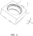
- FIG. 2 is a perspective view of an external appearance of camera module A.
- FIG. 3 is an exploded perspective view of camera module A.
- Camera module A is mounted such that the vertical direction (or horizontal direction) is the X direction, the horizontal direction (or vertical direction) is the Y direction, and the front-rear direction is the Z direction at the time of actually capturing an image with smartphone M.
- the Z direction is the light axis direction
- the upper side in the drawing is the light reception side in the light axis direction (also referred to as “macro position side")
- the lower side is the imaging side in the light axis direction (also referred to as "infinity position side”).
- Camera module A includes a lens part (not illustrated) in which a lens is housed in a lens barrel having a cylindrical shape, auto-focusing and shake-correcting lens driving device 1, an image capturing part (not illustrated) that captures a subject image imaged with the lens part, shield cover 2 that covers the entirety, and the like.
- shield cover 2 is a capped square cylindrical body having a square shape in plan view. Circular opening 2a is formed in the top surface of shield cover 2. A lens part (not illustrated) is exposed to the outside through opening 2a. Shield cover 2 includes, at the bottom part, engagement piece 2b for mounting to lens driving device 1 (base member 23). Engagement piece 2b protrudes downward from the bottom part of shield cover 2.
- the image capturing part includes an imaging device (not illustrated), and is disposed on the imaging side in the light axis direction of the lens driving device 1.
- the imaging device (not illustrated) is composed of, for example, a CCD (charge coupled device) image sensor, a CMOS (complementary metal oxide semiconductor) image sensor, or the like.
- the imaging device (not illustrated) captures a subject image imaged by a lens part (not illustrated).
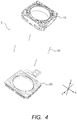
- FIG. 4 is an exploded perspective view of lens driving device 1.
- lens driving device 1 includes OIS movable part 10, OIS fixing part 20, supporting member 30 and the like.
- OIS movable part 10 is a part that includes one of an OIS coil part and an OIS magnet part for forming the OIS voice coil motor, and sways in the XY plane at the time of shake correction.
- OIS fixing part 20 is a part that includes the other of the OIS coil part and the OIS magnet part.
- the OIS magnet part is disposed in OIS movable part 10
- the OIS coil part is disposed in OIS fixing part 20.
- OIS movable part 10 is the "AF unit" including the AF driving part.
- OIS movable part 10 is disposed on the light reception side in the light axis direction relative to OIS fixing part 20 and is separated from OIS fixing part 20.
- OIS movable part 10 is coupled with OIS fixing part 20 by supporting member 30.
- supporting member 30 is composed of four suspension wires extending along the Z direction (hereinafter referred to as "suspension wire 30").
- One end (upper end) of suspension wire 30 is fixed to OIS movable part 10 (upper elastic supporting part 13), and the other end (lower end) of suspension wire 30 is fixed to OIS fixing part 20 (coil substrate 21).
- OIS movable part 10 is supported by suspension wire 30 such that OIS movable part 10 can sway in the XY plane.
- suspension wires 30 are used for feeding power to AF coil part 112.
- the number of suspension wires 30 is not limited to four as long as a plurality of suspension wires 30 are provided.
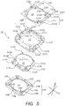
- FIG. 5 is an exploded perspective view of OIS movable part 10.
- FIG. 6 is a perspective view of an upper side of OIS movable part 10.
- FIG. 7 is a perspective view of a lower side of OIS movable part 10.
- OIS movable part 10 includes AF movable part 11, AF fixing part 12, upper elastic supporting part 13, lower elastic supporting part 14 and the like.
- AF movable part 11 includes one of the AF coil part and the AF magnet part for forming the AF voice coil motor, and moves at the time of focusing in the light axis direction.
- AF fixing part 12 includes the other of the AF coil part and the AF magnet part.
- the AF coil part is disposed in AF movable part 11, and the AF magnet part is disposed in AF fixing part 12.
- AF movable part 11 is disposed on the radially inside relative to AF fixing part 12 and is separated from AF fixing part 12.
- AF movable part 11 is coupled with AF fixing part 12 by upper elastic supporting part 13 and lower elastic supporting part 14.
- AF movable part 11 includes lens holder 111 and AF coil part 112.
- Lens holder 111 is a member having a cylindrical shape, and a lens part (not illustrated) is fixed on the inner peripheral surface by bonding or screwing.
- Lens holder 111 includes, at the lower half portion of the peripheral surface, coil winding part 111a having a chamfered quadrangular shape.
- Flat surface 111b of coil winding part 111a serves as a locking part (hereinafter referred to as "first locking part 111b") for limiting the movement of AF movable part 11 toward the light reception side in the light axis direction.
- Lens holder 111 includes, at four portions intersecting the X direction and the Y direction (hereinafter referred to as "cross direction") of the upper half portion of the peripheral surface, protruding parts 111c that radially outwardly protrude.
- Protruding parts 111c serve as locking parts (hereinafter referred to as “second locking parts 111c") for limiting the movement of AF movable part 11 toward the imaging side in the light axis direction. Second locking parts 111c radially outwardly protrude over coil winding part 111a.
- Lens holder 111 includes, at four portions intersecting the directions (hereinafter referred to as “diagonal direction”) rotated by 45 degrees from the cross direction of the upper half portion of the peripheral surface, protruding parts 111d.
- Protruding parts 111d serve as upper spring fixing parts (hereinafter referred to as “upper spring fixing parts 111d”) for fixing upper elastic supporting part 13.
- Upper bosses 111e for positioning and fixing upper elastic supporting part 13 are disposed at upper spring fixing parts 111d.
- tying parts 111h that radially outwardly protrude are disposed at two opposite upper spring fixing parts 111d of the four upper spring fixing parts 111d.
- Lens holder 111 includes, at the four corners of the bottom surface, lower spring fixing parts 111f for fixing lower elastic supporting part 14. Lower bosses 111g for positioning and fixing lower elastic supporting part 14 are disposed at lower spring fixing parts 111f.
- AF coil part 112 is an air-core coil that is energized at the time of focusing, and is wound around the outer peripheral surface of coil winding part 111a of lens holder 111.
- One end of AF coil part 112 is tied to one tying part 111h, and the other end of AF coil part 112 is tied to the other tying part 111h.
- AF fixing part 12 includes magnet holder 121 and magnet part 122. While FIG. 5 illustrates a state where magnet holder 121 is attached on magnet part 122, magnet part 122 is attached after AF movable part 11 is inserted to magnet holder 121 in practice.
- Magnet holder 121 has a quadrangular cylindrical shape which is square in plan view.
- Four connection parts (four sides extending along the Z-axis direction) connecting the side walls of magnet holder 121 are curved to radially inside (curved parts 121a).
- Suspension wires 30 are disposed at curved parts 121a.
- Magnet holder 121 includes, at the upper part, stopper parts 121b that protrude to radially inside in a ring-shape. Stopper parts 121b include first cutout parts 121c at the four portions intersecting the cross direction, and second cutout parts 121d at the four portions intersecting diagonal direction.
- First cutout parts 121c correspond to second locking parts 111c of lens holder 111
- second cutout parts 121d correspond to upper spring fixing parts 111d of lens holder 111.
- Magnet holder 121 includes, at the four corners of the top surface, upper spring fixing parts 121e that fix upper elastic supporting part 13.
- Upper bosses 121f for fixing and positioning upper elastic supporting part 13 are disposed at upper spring fixing parts 121e.
- the portion around upper boss 121f having a trapezoidal columnar shape is slightly recessed relative to the top surface of magnet holder 121 (damper installation part 121i) such that a gap is formed when upper leaf springs 13A and 13B are attached thereto.
- the corner portion of damper installation part 121i (the upper part of curved parts 121a) protrudes to the outside relative to the lower part.
- Magnet holder 121 includes, at the four corners of the bottom surface, lower spring fixing parts 121g that fix lower elastic supporting part 14. Lower bosses 121h for fixing and positioning lower elastic supporting part 14 are disposed at lower spring fixing parts 121g.
- Magnet part 122 includes four cuboid permanent magnets 122A to 122D.
- Permanent magnets 122A to 122D are disposed along the internal surfaces of the four side walls of magnet holder 121.
- Permanent magnets 122A and 122C are disposed to face each other in the Y direction, and permanent magnets 122B and 122D are disposed to face each other in the X direction.
- Permanent magnets 122A to 122D are magnetized such that a magnetic field orthogonal to the radial direction is formed at AF coil part 112.
- permanent magnets 122A to 122D are magnetized such that the inner periphery side and the outer periphery side thereof are set to N pole and S pole, respectively.
- the AF voice coil motor is composed of magnet part 122 and AF coil part 112.
- magnet part 122 serves as the AF magnet part and as the OIS magnet part.
- Upper elastic supporting part 13 is a leaf spring made of beryllium copper, nickel copper, stainless steel or the like for example, and is composed of two members 13A and 13B having the same shape (hereinafter referred to as "upper leaf springs 13A and 13B"). Upper leaf springs 13A and 13B are point symmetrical about the optical axis, and upper elastic supporting part 13 has a square shape in plan view in its entirety.
- Each of upper leaf springs 13A and 13B includes spring parts 131 and 132.
- Spring part 131 includes lens holder fixing part 131a that is fixed to lens holder 111, magnet holder fixing part 131b that is disposed at a position rotated by 90 degrees from lens holder fixing part 131a and is fixed to magnet holder 121, and arm part 131c that couples lens holder fixing part 131a and magnet holder fixing part 131b.
- spring part 132 includes lens holder fixing part 132a, magnet holder fixing part 132b, and arm part 132c. Lens holder fixing parts 131a and 132a are coupled at a position on the inside of arm part 131c, and magnet holder fixing parts 131b and 132b are coupled at a position on the outside of arm part 132c.
- Lens holder fixing parts 131a and 132a include fixation holes 131d and 132d corresponding to upper bosses 111e of lens holder 111.
- Magnet holder fixing parts 131b and 132b include fixation holes 131e and 132e corresponding to upper bosses 121f of magnet holder 121.
- magnet holder fixing parts 131b and 132b include wire fixation holes 131f and 132f through which one end of suspension wire 30 is inserted.
- the portions where wire fixation holes 131f and 132f are formed are formed such that the portions are easily elastically deformed. The drop impact is absorbed by deflection of the portions where wire fixation holes 131f and 132f are formed and suspension wire 30, and therefore plastic deformation or rupture of suspension wire 30 does not occur.
- lower elastic supporting part 14 is a leaf spring made of beryllium copper, nickel copper, stainless-steel or the like (hereinafter referred to as "lower leaf spring 14").
- Lower leaf spring 14 includes four spring parts 141 to 144.
- Each of spring parts 141 to 144 includes lens holder fixing part 14a that is fixed to lens holder 111, magnet holder fixing part 14b that is disposed at a position rotated by 90 degrees from lens holder fixing part 14a and is fixed to magnet holder 121, and arm part 14c that couples lens holder fixing part 14a and magnet holder fixing part 14b.
- Lens holder fixing parts 14a adjacent to each other are coupled by inner ring part 14f at a position on the inside of arm part 14c.
- Magnet holder fixing parts 14b adjacent to each other are coupled by outer ring part 14g at a position on the outside of arm part 14c.
- Lens holder fixing part 14a includes fixation hole 14d corresponding to lower boss 111g of lens holder 111.
- Magnet holder fixing part 14b includes fixation hole 14e corresponding to lower boss 121h of magnet holder 121.
- magnet holder fixing parts 131b and 132b of upper leaf springs 13A and 13B are attached to upper spring fixing parts 121e of magnet holder 121.
- lens holder fixing parts 14a of lower leaf spring 14 are attached to lower spring fixing parts 111f of lens holder 111.
- lens holder 111 is fitted into magnet holder 121 from the imaging side in the light axis direction.
- second locking parts 111c of lens holder 111 are fitted to first cutout parts 121c of magnet holder 121
- upper spring fixing parts 111d are fitted to second cutout parts 121d.
- lens holder fixing parts 131a and 132a of upper leaf springs 13A and 13B are attached to upper spring fixing parts 111d of lens holder 111.
- Lens holder fixing part 131a is bonded by soldering to one end and the other end of AF coil part 112 tied to tying part 111h of lens holder 111, so as to be electrically connected.
- magnet holder fixing parts 14b of lower leaf spring 14 are attached to lower spring fixing parts 121g of magnet holder 121.
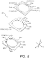
- FIG. 8 is an exploded perspective view of OIS fixing part 20.
- OIS fixing part 20 includes coil substrate 21, sensor substrate 22, base member 23 and the like.
- coil substrate 21 has a square shape, and has circular opening 21a at a center portion.
- Coil substrate 21 includes, at the four corners, wire fixation holes 21b through which the other end (lower end) of suspension wire 30 is inserted.
- coil substrate 21 includes, at positions which intersect the diagonal direction of peripheral portions of opening 21a, positioning holes 21c.
- Coil substrate 21 includes OIS coil part 211 at a position opposite to magnet part 122 in the light axis direction.
- OIS coil part 211 includes four OIS coils 211A to 211D corresponding to permanent magnets 122A to 122D.
- the sizes and positions of OIS coils 211A to 211D and permanent magnets 122A to 122D are set such that the magnetic field radiated from the bottom surfaces of permanent magnets 122A to 122D traverses the long side portions of OIS coils 211A to 211D in the Z direction.
- the OIS voice coil motor is composed of magnet part 122 and OIS coil part 211.
- sensor substrate 22 has a square shape in plan view, and has circular opening 22a at a center portion.
- Sensor substrate 22 includes, at peripheral portions of opening 22a, positioning holes 22b at positions corresponding to positioning holes 21c of coil substrate 21.
- Sensor substrate 22 includes, at the two sides along the X direction, first lock pieces 22c that are bent downward.
- sensor substrate 22 includes, at the two sides along the Y direction, second lock pieces 22d that are bent downward.
- Sensor substrate 22 includes position detection part 222 that detects the position of OIS movable part 10 in the XY plane, a power-source line (not illustrated) for supplying power to AF coil part 112 and OIS coil part 211, and a signal line for detection signals (not illustrated) output from position detection part 222.
- Position detection part 222 is composed of Hall devices 222A and 222B (magnetic sensors) that detect the magnetic field by utilizing Hall effect, for example.
- Hall devices 222A and 222B are disposed at respective adjacent two sides of the bottom surface of sensor substrate 22 at an approximate center thereof.
- a magnet for position detection may be disposed independently of magnet part 122 in OIS movable part 10.
- base member 23 has a square shape in plan view, and has circular opening 23a at a center portion.
- Base member 23 includes, at peripheral portions of opening 23a, positioning bosses 23b at positions corresponding to positioning holes 21c of coil substrate 21 and positioning holes 22b of sensor substrate 22.
- base member 23 includes, at peripheral portions of opening 23a, Hall device housing parts 23e at positions corresponding to Hall devices 222A and 222B.
- base member 23 includes, at the side walls, small recesses 23c at positions corresponding to first lock pieces 22c of sensor substrate 22, and large recesses 23d at positions corresponding to second lock pieces 22d of sensor substrate 22. Small recesses 23c and large recesses 23d are formed in a tapered shape which expands downward.
- positioning holes 21c of coil substrate 21 and positioning holes 22b of sensor substrate 22 are fitted to positioning bosses 23b of base member 23 to dispose coil substrate 21 and sensor substrate 22 on base member 23.
- First lock pieces 22c of sensor substrate 22 are engaged with small recesses 23c of base member 23, and second lock pieces 22d of sensor substrate 22 are engaged with large recesses 23d, and thus, coil substrate 21 and sensor substrate 22 are fixed to base member 23.
- OIS fixing part 20 are assembled.
- suspension wire 30 is inserted to wire fixation holes 131f and 132f of upper leaf springs 13A and 13B and is fixed by soldering. In this manner, suspension wire 30 and upper leaf springs 13A and 13B are electrically connected to each other.
- suspension wire 30 is inserted to wire fixation hole 21b of coil substrate 21, and is fixed by soldering. In this manner, the power-source line of sensor substrate 22 and suspension wire 30 are electrically connected to each other. Through suspension wire 30 and upper leaf springs 13A and 13B, power can be fed to AF coil part 112.
- a damper (not illustrated) is disposed at damper installation part 121i (including the inside of the protruding portion) of magnet holder 121 in such a manner as to surround suspension wire 30.
- the damper is interposed between magnet holder 121 and upper leaf springs 13A and 13B.
- the damper can be readily applied to damper installation part 121i with use of a dispenser.
- ultraviolet curing silicone gel can be adopted as the damper.
- Shield cover 2 is attached to lens driving device 1 in such a manner that engagement piece 2b of shield cover 2 makes contact with first lock piece 22c of sensor substrate 22. Since small recess 23c of base member 23 has a tapered shape, a biasing force acts between first lock piece 22c of sensor substrate 22 and engagement piece 2b of shield cover 2. Accordingly, shield cover 2 and sensor substrate 22 are electrically connected to each other without soldering. In this manner, shield cover 2 can be readily grounded, and EMC noise can be blocked.
- OIS coil part 211 When performing shake correction in lens driving device 1, OIS coil part 211 is energized.
- the energization current supplied through OIS coil part 211 is controlled by an external control part (not illustrated).
- OIS coil part 211 When OIS coil part 211 is energized, a Lorentz force is generated at OIS coil part 211 by interaction between the magnetic field of magnet part 122 and the current flowing through OIS coil part 211 (Fleming's left hand rule).
- the direction of the Lorentz force is the direction (the Y direction or the X direction) orthogonal to the direction of the magnetic field (the Z direction) and the direction of the current flowing through the long side portion of OIS coil part 211 (the X direction or the Y direction).
- AF coil part 112 When performing automatic focusing in lens driving device 1, AF coil part 112 is energized.
- the energization current supplied through AF coil part 112 is controlled by an external control part (not illustrated).
- AF coil part 112 When AF coil part 112 is energized, a Lorentz force is generated at AF coil part 112 by interaction between the magnetic field of magnet part 122 and the current flowing through AF coil part 112.
- the direction of the Lorentz force is a direction (the Z direction) orthogonal to the direction of the magnetic field (X direction or Y direction) and the direction of the current flowing through the AF coil part 211 (the Y direction or the X direction). Since magnet part 122 is fixed, a reactive force acts on AF coil part 112. With this reactive force serving as the driving force of the AF voice coil motor, AF movable part 11 having AF coil part 112 moves in the light axis direction, and thus focusing is performed.
- AF movable part 11 is suspended between the infinity position and the macro position with upper leaf springs 13A and 13B and lower leaf spring 14 (hereinafter referred to as "reference state"). That is, in OIS movable part 10, AF movable part 11 (lens holder 111) is elastically supported such that AF movable part 11 is displaceable in the Z direction in the state where the position of AF movable part 11 with respect to AF fixing part 12 (magnet holder 121) is set by upper leaf springs 13A and 13B, and lower leaf spring 14.
- the direction of the current is controlled based on whether AF movable part 11 is moved from the reference state toward the macro position side or to the infinity position side.
- the value of the current is controlled in accordance with the movement length of AF movable part 11.
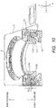
- FIG. 9 is a perspective sectional view of a stopper structure for limiting the movement of AF movable part 11 toward the infinity position side.
- FIG. 9 illustrates a case where AF movable part 11 is in a reference state.
- second locking part 111c of lens holder 111 approaches the top surface of magnet part 122. Then, second locking part 111c of lens holder 111 makes contact with the top surface of magnet part 122 when AF movable part 11 is moved by stroke S1, and thus the movement is limited.
- the position where second locking parts 111c of lens holder 111 makes contact with the top surface of magnet part 122 is the infinity position.
- FIG. 10 is a perspective sectional view illustrating a stopper structure for limiting the movement of AF movable part 11 toward the macro position side.
- FIG. 10 illustrates AF movable part 11 in the reference state.
- first locking part 111b of lens holder 111 approaches stopper part 121b of magnet holder 121. Then, first locking part 111b of lens holder 111 makes contact with stopper part 121b of magnet holder 121 when AF movable part 11 is moved by stroke S2, and thus the movement is limited.
- the position where first locking part 111c of lens holder 111 makes contact with stopper part 121b of magnet holder 121 is the macro position.
- Lens driving device 1 includes: AF driving part including AF coil part 112 disposed around a lens part, and an AF magnet part disposed separately from AF coil part 112 in a radial direction, the AF driving part being configured to automatically perform focusing by moving AF movable part 11 including AF coil part 112 in a light axis direction with respect to AF fixing part 12 including the AF magnet part by use of a driving force of a voice coil motor composed of AF coil part 112 and the AF magnet part.
- lens driving device 1 also includes: an OIS driving part including OIS magnet part 122 disposed at an AF unit having AF movable part 11 and AF fixing part 12, and OIS coil part 211 disposed separately from OIS magnet part 122 in the light axis direction, the OIS driving part being configured to configured to perform shake correction by swaying OIS movable part 10 including OIS magnet part 122 in a plane orthogonal to the light axis direction with respect to OIS fixing part 20 including OIS coil part 211 by use of a driving force of a voice coil motor composed of OIS coil part 211 and OIS magnet part 122.
- OIS driving part including OIS magnet part 122 disposed at an AF unit having AF movable part 11 and AF fixing part 12, and OIS coil part 211 disposed separately from OIS magnet part 122 in the light axis direction
- the OIS driving part being configured to configured to perform shake correction by swaying OIS movable part 10 including OIS magnet part 122 in a plane orthogonal
- the AF driving part includes an elastic supporting part (upper elastic supporting part 13, lower elastic supporting part 14) configured to connect AF movable part 11 and AF fixing part 12; and AF movable part 11 is supported by elastic supporting part 13, 14 such that AF movable part 11 is movable in the light axis direction.
- AF movable part 11 can move in the light axis direction with the reference state as the center, and therefore even with the movable range of AF movable part 11 (the range from the infinity position to the macro position), the movement amount of AF movable part 11 is small, and the displacement amount of upper elastic supporting part 13 and lower elastic supporting part 14 (the maximum displacement amount and the integrated displacement amount) is obviously small in comparison with the conventional lens driving device (see PTL 1). Accordingly, power consumption at the time of focusing can be reduced, and thus further power saving can be achieved. In addition, since the size of the voice coil motor of the AF driving part (AF coil part 112 and magnet part 122) can be reduced, further downsizing can be achieved. Further, it is not necessary to provide a spacer in the conventional lens driving device, and the number of components can be reduced. As a result, the assembly work can be simplified, and downsizing and height reduction can be achieved.
- AF fixing part 12 includes a stopper part (stopper part 121b, the top surface of magnet part 122) configured to limit movement of AF movable part 11 in the light axis direction; and AF movable part 11 includes locking part (first locking part 111b, second locking parts 111c) that is locked by stopper part 121b, 122.
- AF fixing part 12 includes, as stopper part 121b, 122, first stopper part 121b configured to limit movement of AF movable part 11 toward a light reception side in the light axis direction, and a second stopper part (the top surface of magnet part 122) configured to limit movement of AF movable part 11 toward an imaging side in the light axis direction.
- AF movable part 11 includes, as the locking part, first locking part 111b that is locked by first stopper part 111b, and second locking part 111c that is locked by second stopper part 111c.
- AF fixing part 12 includes magnet holder 121 in which the AF magnet part (magnet part 122) is disposed; and the magnet holder 121 includes at least one of first stopper part 111b and second stopper part 111c.
- the AF magnet part (magnet part 122) forms the second stopper part configuration.
- AF movable part 11 includes a lens holder in which AF coil part 112 is disposed; and lens holder 111 includes at least one of first locking part 111b and second locking part 111c.
- AF movable part 11 can be surely moved within an appropriate movable range. Accordingly, it is possible to prevent a situation where AF movable part 11 makes contact with OIS fixing part 20 due to malfunction or the like and the components are damaged or the OIS function is impaired.
- magnet holder 121 may be provided with the second stopper part, and magnet part 122 may be provided with the first stopper part.
- the stopper part and the locking part may be composed of other members.
- the present invention is also applicable to camera-equipped mobile phones, note-type personal computers, tablet terminals, mobile game machines, webcameras, in-vehicle cameras and the like.
Abstract
Description
- The present invention relates to a lens driving device for auto focus and shake correction, and a camera module and a camera-equipped mobile terminal having an auto focus function and a shake correction function.
- In general, a small-sized camera module is mounted in mobile terminals such as a smartphone. As such a camera module, a lens driving device (for example PTL 1) is employed. The lens driving device has an auto focus function of automatically performing focusing for capturing a subject (hereinafter referred to as "AF (Auto Focus) function"), and a shake correction function (hereinafter referred to as "OIS (Optical Image Stabilization) function") of optically correcting hand shake (vibration) upon capturing an image to reduce the irregularities of the image.
- The auto-focusing and shake-correcting lens driving device includes an auto-focusing driving part (hereinafter referred to as "AF driving part") for moving the lens part in the light axis direction, and a shake-correcting driving part (hereinafter referred to as "OIS driving part") for swaying the lens part in a plane orthogonal to the light axis direction.
- The AF driving part includes, for example, an auto-focusing coil part (hereinafter referred to as "AF coil part") disposed around the lens part, and an auto-focusing magnet part (hereinafter referred to as "AF magnet part") disposed separately from the AF coil part in the radial direction. An auto-focusing movable part (hereinafter referred to as "AF movable part") including the lens part and the AF coil part is moved with respect to an auto-focusing fixing part (hereinafter referred to as "AF fixing part") including the AF magnet part in the light axis direction by use of a driving force of a voice coil motor composed of the AF coil part and the AF magnet part, and thus focusing is automatically performed. In the following, the AF movable part and the AF fixing part are collectively referred to as "auto-focusing unit (AF unit)."
- Here, a lens position for bringing a subject at a smallest capture distance (a position on the most light reception side) into focus is called "macro position," and a lens position for bringing a subject at the infinity (a position on the most imaging side) into focus is called "infinity position." That is, the range from the macro position to the infinity position is the movable range of the AF movable part.
- The OIS driving part includes, for example, an OIS magnet part disposed in the AF unit, and an OIS coil part disposed separately from the OIS magnet part in the light axis direction. The OIS movable part (the AF unit and the OIS magnet part) is supported by a supporting member separately from the OIS fixing part (OIS coil part) in the light axis direction. The OIS movable part is swayed in a plane orthogonal to the light axis direction by use of a driving force of a voice coil motor composed of the OIS magnet part and the OIS coil part, and thus shake correction is performed.
- The OIS magnet part may also serve as the AF magnet part, and with such a configuration, the size and the height of the lens driving device can be reduced.
- In the lens driving device disclosed in
PTL 1, an elastic supporting part (an upper leaf spring and a lower leaf spring) connects a lens holder (as a part of the AF movable part) in which the AF coil part is disposed at the outer peripheral surface, with a magnet holder (as a part of AF fixing part) in which the AF magnet part (also serve as the OIS magnet part) is disposed. At the time of focusing, the AF movable part moves in the light axis direction until the driving force (driving power) of the voice coil motor of the AF driving part and the restoration force of the elastic supporting part are equivalent to each other, and the AF movable part is held in that state. Accordingly, a driving force corresponding to the restoration force of the lower leaf spring and the upper leaf spring in the maximum displacement state is required for the voice coil motor of the AF driving part. - In addition, in the lens driving device disclosed in
PTL 1, a spacer is disposed to the lower leaf spring on the imaging side in order to limit the movement of the AF movable part toward the imaging side in the light axis direction. Thus, in the lens driving device disclosed inPTL 1, in an non-energization state where focusing is not performed, the AF movable part is biased, with the back tension of the upper leaf spring and the lower leaf spring, to the spacer side and is brought to the closest position (seeFIG. 2 of PTL 1). That is, the AF movable part is held at the infinity position in a non-energization state where focusing is not performed, and is moved toward the macro position in an energization state where focusing is performed. -
PTL 1
Japanese Patent Application Laid-Open No.2013-210550 - In recent years, along with reduction in thickness of mobile terminals, further downsizing and power saving of camera modules are desired. With the above-described conventional structure, however, it is difficult to achieve further downsizing and power saving of camera modules. In addition, it is not easy to employ the increasingly improving function of mobile terminals (rising magnification of camera modules).
- An object of the present invention is to provide a lens driving device which can achieve further downsizing and power saving, and a camera module and a camera-equipped mobile terminal including the same.
- A lens driving device according to an embodiment of the present invention includes: an auto-focusing driving part including an auto-focusing coil part disposed around a lens part, and an auto-focusing magnet part disposed separately from the auto-focusing coil part in a radial direction, the auto-focusing driving part being configured to automatically perform focusing by moving an auto-focusing movable part including the auto-focusing coil part in a light axis direction with respect to an auto-focusing fixing part including the auto-focusing magnet part by use of a driving force of a voice coil motor composed of the auto-focusing coil part and the auto-focusing magnet part; and a shake-correcting driving part including a shake-correcting magnet part disposed at an auto-focusing unit having the auto-focusing movable part and the auto-focusing fixing part, and a shake-correcting coil part disposed separately from the shake-correcting magnet part in the light axis direction, the shake-correcting driving part being configured to perform shake correction by swaying a shake correction movable part including the shake-correcting magnet part in a plane orthogonal to the light axis direction with respect to a shake correction fixing part including the shake-correcting coil part by use of a driving force of a voice coil motor composed of the shake-correcting coil part and the shake-correcting magnet part. The auto-focusing driving part includes an elastic supporting part configured to connect the auto-focusing movable part and the auto-focusing fixing part; and the auto-focusing movable part is supported by the elastic supporting part such that the auto-focusing movable part is movable in the light axis direction.
- A camera module according to an embodiment of the present invention includes: the above-mentioned lens driving device; a lens part that is mounted in the auto-focusing movable part; and an image capturing part configured to capture a subject image imaged with the lens part.
- A camera-equipped mobile terminal according to an embodiment of the present invention includes: the above-mentioned camera module.
- According to the embodiment of the present invention, at the time of focusing, the AF movable part can move in the light axis direction, and therefore even with the movable range of the AF movable part (the range from the infinity position to the macro position), the movement amount of the AF movable part is small, and the displacement amount of the elastic supporting part (the maximum displacement amount and the integrated displacement amount) is obviously small in comparison with the conventional lens driving device. Accordingly, power consumption at the time of focusing can be reduced, and thus further power saving can be achieved. In addition, since the size of the voice coil motor of the AF driving part (the AF coil part and the magnet part) can be reduced, further downsizing can be achieved.
-
-
FIGS. 1A and 1B illustrate a smartphone in which a camera module according to an embodiment of the present invention is mounted; -
FIG. 2 is a perspective view of an external appearance of the camera module; -
FIG. 3 is an exploded perspective view of the camera module; -
FIG. 4 is an exploded perspective view of a lens driving device; -
FIG. 5 is an exploded perspective view of an OIS movable part; -
FIG. 6 is a perspective view of an upper side of the OIS movable part; -
FIG. 7 is a perspective view of a lower side of the OIS movable part; -
FIG. 8 is an exploded perspective view of an OIS fixing part; -
FIG. 9 is a perspective sectional view of a structure of a first stopper in the camera module; and -
FIG. 10 is a perspective sectional view of a second stopper structure in the camera module. - In the following, an embodiment of the present invention is described in detail with reference to the drawings.
-
FIGS. 1A and 1B illustrate smartphone M in which camera module A according to the embodiment of the present invention is mounted.FIG. 1A is a front view of smartphone M, andFIG. 1B is a rear view of smartphone M. - For example, smartphone M is provided with camera module A as a back side camera OC. Camera module A has an auto focus function and a shake correction function, and can capture an image without image blurring by automatically performing focusing at the time of capturing a subject and by optically correcting hand shake (vibration) caused at the time of capturing an image.
-
FIG. 2 is a perspective view of an external appearance of camera module A.FIG. 3 is an exploded perspective view of camera module A. - As illustrated in
FIG. 2 andFIG. 3 , descriptions will be made with an orthogonal coordinate system (X, Y, Z) in the present embodiment. Also inFIG. 4 to FIG. 10 described later, descriptions will be made with an orthogonal coordinate system (X, Y, Z). Camera module A is mounted such that the vertical direction (or horizontal direction) is the X direction, the horizontal direction (or vertical direction) is the Y direction, and the front-rear direction is the Z direction at the time of actually capturing an image with smartphone M. That is, the Z direction is the light axis direction, the upper side in the drawing is the light reception side in the light axis direction (also referred to as "macro position side"), and the lower side is the imaging side in the light axis direction (also referred to as "infinity position side"). - Camera module A includes a lens part (not illustrated) in which a lens is housed in a lens barrel having a cylindrical shape, auto-focusing and shake-correcting
lens driving device 1, an image capturing part (not illustrated) that captures a subject image imaged with the lens part,shield cover 2 that covers the entirety, and the like. - As viewed in the light axis direction,
shield cover 2 is a capped square cylindrical body having a square shape in plan view.Circular opening 2a is formed in the top surface ofshield cover 2. A lens part (not illustrated) is exposed to the outside throughopening 2a.Shield cover 2 includes, at the bottom part,engagement piece 2b for mounting to lens driving device 1 (base member 23).Engagement piece 2b protrudes downward from the bottom part ofshield cover 2. - The image capturing part (not illustrated) includes an imaging device (not illustrated), and is disposed on the imaging side in the light axis direction of the
lens driving device 1. The imaging device (not illustrated) is composed of, for example, a CCD (charge coupled device) image sensor, a CMOS (complementary metal oxide semiconductor) image sensor, or the like. The imaging device (not illustrated) captures a subject image imaged by a lens part (not illustrated). -
FIG. 4 is an exploded perspective view oflens driving device 1. - As illustrated in
FIG. 4 ,lens driving device 1 includes OISmovable part 10,OIS fixing part 20, supportingmember 30 and the like. OISmovable part 10 is a part that includes one of an OIS coil part and an OIS magnet part for forming the OIS voice coil motor, and sways in the XY plane at the time of shake correction.OIS fixing part 20 is a part that includes the other of the OIS coil part and the OIS magnet part. In the present embodiment, the OIS magnet part is disposed in OISmovable part 10, and the OIS coil part is disposed inOIS fixing part 20. In addition, OISmovable part 10 is the "AF unit" including the AF driving part. - OIS
movable part 10 is disposed on the light reception side in the light axis direction relative toOIS fixing part 20 and is separated fromOIS fixing part 20. OISmovable part 10 is coupled withOIS fixing part 20 by supportingmember 30. To be more specific, supportingmember 30 is composed of four suspension wires extending along the Z direction (hereinafter referred to as "suspension wire 30"). One end (upper end) ofsuspension wire 30 is fixed to OIS movable part 10 (upper elastic supporting part 13), and the other end (lower end) ofsuspension wire 30 is fixed to OIS fixing part 20 (coil substrate 21). OISmovable part 10 is supported bysuspension wire 30 such that OISmovable part 10 can sway in the XY plane. - It is to be noted that two of the four
suspension wires 30 are used for feeding power toAF coil part 112. In addition, the number ofsuspension wires 30 is not limited to four as long as a plurality ofsuspension wires 30 are provided. -
FIG. 5 is an exploded perspective view of OISmovable part 10.FIG. 6 is a perspective view of an upper side of OISmovable part 10.FIG. 7 is a perspective view of a lower side of OISmovable part 10. - As illustrated in
FIG. 5 to FIG. 7 , OISmovable part 10 includes AFmovable part 11,AF fixing part 12, upper elastic supportingpart 13, lower elastic supportingpart 14 and the like. AFmovable part 11 includes one of the AF coil part and the AF magnet part for forming the AF voice coil motor, and moves at the time of focusing in the light axis direction.AF fixing part 12 includes the other of the AF coil part and the AF magnet part. - In the present embodiment, the AF coil part is disposed in AF
movable part 11, and the AF magnet part is disposed inAF fixing part 12. AFmovable part 11 is disposed on the radially inside relative toAF fixing part 12 and is separated fromAF fixing part 12. AFmovable part 11 is coupled withAF fixing part 12 by upper elastic supportingpart 13 and lower elastic supportingpart 14. - AF
movable part 11 includeslens holder 111 andAF coil part 112. -
Lens holder 111 is a member having a cylindrical shape, and a lens part (not illustrated) is fixed on the inner peripheral surface by bonding or screwing. -
Lens holder 111 includes, at the lower half portion of the peripheral surface,coil winding part 111a having a chamfered quadrangular shape.Flat surface 111b ofcoil winding part 111a serves as a locking part (hereinafter referred to as "first lockingpart 111b") for limiting the movement of AFmovable part 11 toward the light reception side in the light axis direction. -
Lens holder 111 includes, at four portions intersecting the X direction and the Y direction (hereinafter referred to as "cross direction") of the upper half portion of the peripheral surface, protrudingparts 111c that radially outwardly protrude. Protrudingparts 111c serve as locking parts (hereinafter referred to as "second locking parts 111c") for limiting the movement of AFmovable part 11 toward the imaging side in the light axis direction. Second lockingparts 111c radially outwardly protrude overcoil winding part 111a. -
Lens holder 111 includes, at four portions intersecting the directions (hereinafter referred to as "diagonal direction") rotated by 45 degrees from the cross direction of the upper half portion of the peripheral surface, protrudingparts 111d. Protrudingparts 111d serve as upper spring fixing parts (hereinafter referred to as "upperspring fixing parts 111d") for fixing upper elastic supportingpart 13. -
Upper bosses 111e for positioning and fixing upper elastic supportingpart 13 are disposed at upperspring fixing parts 111d. In addition, tyingparts 111h that radially outwardly protrude are disposed at two opposite upperspring fixing parts 111d of the four upperspring fixing parts 111d. -
Lens holder 111 includes, at the four corners of the bottom surface, lowerspring fixing parts 111f for fixing lower elastic supportingpart 14.Lower bosses 111g for positioning and fixing lower elastic supportingpart 14 are disposed at lowerspring fixing parts 111f. -
AF coil part 112 is an air-core coil that is energized at the time of focusing, and is wound around the outer peripheral surface ofcoil winding part 111a oflens holder 111. One end ofAF coil part 112 is tied to one tyingpart 111h, and the other end ofAF coil part 112 is tied to the other tyingpart 111h. -
AF fixing part 12 includesmagnet holder 121 andmagnet part 122. WhileFIG. 5 illustrates a state wheremagnet holder 121 is attached onmagnet part 122,magnet part 122 is attached after AFmovable part 11 is inserted tomagnet holder 121 in practice. -
Magnet holder 121 has a quadrangular cylindrical shape which is square in plan view. Four connection parts (four sides extending along the Z-axis direction) connecting the side walls ofmagnet holder 121 are curved to radially inside (curved parts 121a).Suspension wires 30 are disposed atcurved parts 121a. -
Magnet holder 121 includes, at the upper part,stopper parts 121b that protrude to radially inside in a ring-shape.Stopper parts 121b includefirst cutout parts 121c at the four portions intersecting the cross direction, andsecond cutout parts 121d at the four portions intersecting diagonal direction. -
First cutout parts 121c correspond tosecond locking parts 111c oflens holder 111, andsecond cutout parts 121d correspond to upperspring fixing parts 111d oflens holder 111. -
Magnet holder 121 includes, at the four corners of the top surface, upperspring fixing parts 121e that fix upper elastic supportingpart 13.Upper bosses 121f for fixing and positioning upper elastic supportingpart 13 are disposed at upperspring fixing parts 121e. The portion aroundupper boss 121f having a trapezoidal columnar shape is slightly recessed relative to the top surface of magnet holder 121 (damper installation part 121i) such that a gap is formed whenupper leaf springs damper installation part 121i (the upper part ofcurved parts 121a) protrudes to the outside relative to the lower part. -
Magnet holder 121 includes, at the four corners of the bottom surface, lowerspring fixing parts 121g that fix lower elastic supportingpart 14.Lower bosses 121h for fixing and positioning lower elastic supportingpart 14 are disposed at lowerspring fixing parts 121g. -
Magnet part 122 includes four cuboidpermanent magnets 122A to 122D.Permanent magnets 122A to 122D are disposed along the internal surfaces of the four side walls ofmagnet holder 121.Permanent magnets permanent magnets Permanent magnets 122A to 122D are magnetized such that a magnetic field orthogonal to the radial direction is formed atAF coil part 112. For example,permanent magnets 122A to 122D are magnetized such that the inner periphery side and the outer periphery side thereof are set to N pole and S pole, respectively. - The AF voice coil motor is composed of
magnet part 122 andAF coil part 112. In the present embodiment,magnet part 122 serves as the AF magnet part and as the OIS magnet part. - Upper elastic supporting
part 13 is a leaf spring made of beryllium copper, nickel copper, stainless steel or the like for example, and is composed of twomembers upper leaf springs Upper leaf springs part 13 has a square shape in plan view in its entirety. - Each of
upper leaf springs spring parts Spring part 131 includes lensholder fixing part 131a that is fixed tolens holder 111, magnetholder fixing part 131b that is disposed at a position rotated by 90 degrees from lensholder fixing part 131a and is fixed tomagnet holder 121, andarm part 131c that couples lensholder fixing part 131a and magnetholder fixing part 131b. Likewise,spring part 132 includes lensholder fixing part 132a, magnetholder fixing part 132b, andarm part 132c. Lensholder fixing parts arm part 131c, and magnetholder fixing parts arm part 132c. - Lens
holder fixing parts fixation holes upper bosses 111e oflens holder 111. Magnetholder fixing parts fixation holes upper bosses 121f ofmagnet holder 121. - In addition, magnet
holder fixing parts suspension wire 30 is inserted. The portions where wire fixation holes 131f and 132f are formed are formed such that the portions are easily elastically deformed. The drop impact is absorbed by deflection of the portions where wire fixation holes 131f and 132f are formed andsuspension wire 30, and therefore plastic deformation or rupture ofsuspension wire 30 does not occur. - As with upper elastic supporting
part 13, lower elastic supportingpart 14 is a leaf spring made of beryllium copper, nickel copper, stainless-steel or the like (hereinafter referred to as "lower leaf spring 14").Lower leaf spring 14 includes fourspring parts 141 to 144. Each ofspring parts 141 to 144 includes lensholder fixing part 14a that is fixed tolens holder 111, magnetholder fixing part 14b that is disposed at a position rotated by 90 degrees from lensholder fixing part 14a and is fixed tomagnet holder 121, andarm part 14c that couples lensholder fixing part 14a and magnetholder fixing part 14b. - Lens
holder fixing parts 14a adjacent to each other are coupled byinner ring part 14f at a position on the inside ofarm part 14c. Magnetholder fixing parts 14b adjacent to each other are coupled byouter ring part 14g at a position on the outside ofarm part 14c. - Lens
holder fixing part 14a includesfixation hole 14d corresponding tolower boss 111g oflens holder 111. Magnetholder fixing part 14b includesfixation hole 14e corresponding to lowerboss 121h ofmagnet holder 121. - At the time of assembling OIS
movable part 10, first, magnetholder fixing parts upper leaf springs spring fixing parts 121e ofmagnet holder 121. In addition, lensholder fixing parts 14a oflower leaf spring 14 are attached to lowerspring fixing parts 111f oflens holder 111. - Next,
lens holder 111 is fitted intomagnet holder 121 from the imaging side in the light axis direction. At this time, second lockingparts 111c oflens holder 111 are fitted tofirst cutout parts 121c ofmagnet holder 121, and upperspring fixing parts 111d are fitted tosecond cutout parts 121d. Then, lensholder fixing parts upper leaf springs spring fixing parts 111d oflens holder 111. Lensholder fixing part 131a is bonded by soldering to one end and the other end ofAF coil part 112 tied to tyingpart 111h oflens holder 111, so as to be electrically connected. In addition, magnetholder fixing parts 14b oflower leaf spring 14 are attached to lowerspring fixing parts 121g ofmagnet holder 121. - Next,
permanent magnets 122A to 122D are inserted from the region surrounded byarm part 14c andouter ring part 14g oflower leaf spring 14, and are bonded tomagnet holder 121. In this manner, OIS movable part 10 (AF driving part) is assembled. -
FIG. 8 is an exploded perspective view ofOIS fixing part 20. - As illustrated in
FIG. 8 ,OIS fixing part 20 includescoil substrate 21,sensor substrate 22,base member 23 and the like. - In plan view,
coil substrate 21 has a square shape, and hascircular opening 21a at a center portion.Coil substrate 21 includes, at the four corners, wire fixation holes 21b through which the other end (lower end) ofsuspension wire 30 is inserted. In addition,coil substrate 21 includes, at positions which intersect the diagonal direction of peripheral portions ofopening 21a,positioning holes 21c. -
Coil substrate 21 includesOIS coil part 211 at a position opposite tomagnet part 122 in the light axis direction.OIS coil part 211 includes four OIScoils 211A to 211D corresponding topermanent magnets 122A to 122D. The sizes and positions of OIS coils 211A to 211D andpermanent magnets 122A to 122D are set such that the magnetic field radiated from the bottom surfaces ofpermanent magnets 122A to 122D traverses the long side portions of OIS coils 211A to 211D in the Z direction. The OIS voice coil motor is composed ofmagnet part 122 andOIS coil part 211. - As with
coil substrate 21,sensor substrate 22 has a square shape in plan view, and hascircular opening 22a at a center portion.Sensor substrate 22 includes, at peripheral portions ofopening 22a,positioning holes 22b at positions corresponding topositioning holes 21c ofcoil substrate 21.Sensor substrate 22 includes, at the two sides along the X direction,first lock pieces 22c that are bent downward. In addition,sensor substrate 22 includes, at the two sides along the Y direction,second lock pieces 22d that are bent downward. -
Sensor substrate 22 includesposition detection part 222 that detects the position of OISmovable part 10 in the XY plane, a power-source line (not illustrated) for supplying power toAF coil part 112 andOIS coil part 211, and a signal line for detection signals (not illustrated) output fromposition detection part 222. -
Position detection part 222 is composed ofHall devices Hall devices sensor substrate 22 at an approximate center thereof. By detecting the magnetic field formed bymagnet part 122 withHall devices movable part 10 in the XY plane can be specified. It is to be noted that a magnet for position detection may be disposed independently ofmagnet part 122 in OISmovable part 10. - As with
coil substrate 21,base member 23 has a square shape in plan view, and hascircular opening 23a at a center portion.Base member 23 includes, at peripheral portions ofopening 23a, positioningbosses 23b at positions corresponding topositioning holes 21c ofcoil substrate 21 andpositioning holes 22b ofsensor substrate 22. In addition,base member 23 includes, at peripheral portions ofopening 23a, Halldevice housing parts 23e at positions corresponding toHall devices base member 23 includes, at the side walls,small recesses 23c at positions corresponding tofirst lock pieces 22c ofsensor substrate 22, andlarge recesses 23d at positions corresponding tosecond lock pieces 22d ofsensor substrate 22.Small recesses 23c andlarge recesses 23d are formed in a tapered shape which expands downward. - At the time of assembling
OIS fixing part 20, first,coil substrate 21 andsensor substrate 22 are bonded by soldering. In this manner, the power-source line (not illustrated) ofsensor substrate 22 andOIS coil part 211 are electrically connected to each other. - Next,
positioning holes 21c ofcoil substrate 21 andpositioning holes 22b ofsensor substrate 22 are fitted to positioningbosses 23b ofbase member 23 to disposecoil substrate 21 andsensor substrate 22 onbase member 23.First lock pieces 22c ofsensor substrate 22 are engaged withsmall recesses 23c ofbase member 23, andsecond lock pieces 22d ofsensor substrate 22 are engaged withlarge recesses 23d, and thus,coil substrate 21 andsensor substrate 22 are fixed tobase member 23. In this manner,OIS fixing part 20 are assembled. - At the time of assembling
lens driving device 1, one end (upper end) ofsuspension wire 30 is inserted to wire fixation holes 131f and 132f ofupper leaf springs suspension wire 30 andupper leaf springs - In addition, the other end (lower end) of
suspension wire 30 is inserted to wirefixation hole 21b ofcoil substrate 21, and is fixed by soldering. In this manner, the power-source line ofsensor substrate 22 andsuspension wire 30 are electrically connected to each other. Throughsuspension wire 30 andupper leaf springs AF coil part 112. - In addition, a damper (not illustrated) is disposed at
damper installation part 121i (including the inside of the protruding portion) ofmagnet holder 121 in such a manner as to surroundsuspension wire 30. Thus the damper is interposed betweenmagnet holder 121 andupper leaf springs damper installation part 121i with use of a dispenser. For example, ultraviolet curing silicone gel can be adopted as the damper. - By interposing the damper (not illustrated) between
magnet holder 121 andupper leaf springs -
Shield cover 2 is attached tolens driving device 1 in such a manner thatengagement piece 2b ofshield cover 2 makes contact withfirst lock piece 22c ofsensor substrate 22. Sincesmall recess 23c ofbase member 23 has a tapered shape, a biasing force acts betweenfirst lock piece 22c ofsensor substrate 22 andengagement piece 2b ofshield cover 2. Accordingly,shield cover 2 andsensor substrate 22 are electrically connected to each other without soldering. In this manner,shield cover 2 can be readily grounded, and EMC noise can be blocked. - When performing shake correction in
lens driving device 1,OIS coil part 211 is energized. The energization current supplied throughOIS coil part 211 is controlled by an external control part (not illustrated). WhenOIS coil part 211 is energized, a Lorentz force is generated atOIS coil part 211 by interaction between the magnetic field ofmagnet part 122 and the current flowing through OIS coil part 211 (Fleming's left hand rule). The direction of the Lorentz force is the direction (the Y direction or the X direction) orthogonal to the direction of the magnetic field (the Z direction) and the direction of the current flowing through the long side portion of OIS coil part 211 (the X direction or the Y direction). SinceOIS coil part 211 is fixed, a reactive force acts onmagnet part 122. With this reactive force serving as the driving force of the OIS voice coil motor, OISmovable part 10 havingmagnet part 122 sways in the XY plane, and thus shake correction is performed. - When performing automatic focusing in
lens driving device 1,AF coil part 112 is energized. The energization current supplied throughAF coil part 112 is controlled by an external control part (not illustrated). WhenAF coil part 112 is energized, a Lorentz force is generated atAF coil part 112 by interaction between the magnetic field ofmagnet part 122 and the current flowing throughAF coil part 112. The direction of the Lorentz force is a direction (the Z direction) orthogonal to the direction of the magnetic field (X direction or Y direction) and the direction of the current flowing through the AF coil part 211 (the Y direction or the X direction). Sincemagnet part 122 is fixed, a reactive force acts onAF coil part 112. With this reactive force serving as the driving force of the AF voice coil motor, AFmovable part 11 havingAF coil part 112 moves in the light axis direction, and thus focusing is performed. - Here, in an non-energization state where focusing is not performed, AF
movable part 11 is suspended between the infinity position and the macro position withupper leaf springs movable part 10, AF movable part 11 (lens holder 111) is elastically supported such that AFmovable part 11 is displaceable in the Z direction in the state where the position of AFmovable part 11 with respect to AF fixing part 12 (magnet holder 121) is set byupper leaf springs lower leaf spring 14. - At the time of focusing, the direction of the current is controlled based on whether AF
movable part 11 is moved from the reference state toward the macro position side or to the infinity position side. In addition, the value of the current is controlled in accordance with the movement length of AFmovable part 11. -
FIG. 9 is a perspective sectional view of a stopper structure for limiting the movement of AFmovable part 11 toward the infinity position side.FIG. 9 illustrates a case where AFmovable part 11 is in a reference state. - As illustrated in
FIG. 9 , when AFmovable part 11 moves to the infinity position side at the time of focusing,second locking part 111c oflens holder 111 approaches the top surface ofmagnet part 122. Then,second locking part 111c oflens holder 111 makes contact with the top surface ofmagnet part 122 when AFmovable part 11 is moved by stroke S1, and thus the movement is limited. The position wheresecond locking parts 111c oflens holder 111 makes contact with the top surface ofmagnet part 122 is the infinity position. -
FIG. 10 is a perspective sectional view illustrating a stopper structure for limiting the movement of AFmovable part 11 toward the macro position side.FIG. 10 illustrates AFmovable part 11 in the reference state. - As illustrated in
FIG. 10 , when AFmovable part 11 moves to the macro position side at the time of focusing, first lockingpart 111b oflens holder 111 approachesstopper part 121b ofmagnet holder 121. Then, first lockingpart 111b oflens holder 111 makes contact withstopper part 121b ofmagnet holder 121 when AFmovable part 11 is moved by stroke S2, and thus the movement is limited. The position where first lockingpart 111c oflens holder 111 makes contact withstopper part 121b ofmagnet holder 121 is the macro position. - As described,
Lens driving device 1 according to the present embodiment includes: AF driving part includingAF coil part 112 disposed around a lens part, and an AF magnet part disposed separately fromAF coil part 112 in a radial direction, the AF driving part being configured to automatically perform focusing by moving AFmovable part 11 includingAF coil part 112 in a light axis direction with respect toAF fixing part 12 including the AF magnet part by use of a driving force of a voice coil motor composed ofAF coil part 112 and the AF magnet part. - In addition,
lens driving device 1 also includes: an OIS driving part includingOIS magnet part 122 disposed at an AF unit having AFmovable part 11 andAF fixing part 12, andOIS coil part 211 disposed separately fromOIS magnet part 122 in the light axis direction, the OIS driving part being configured to configured to perform shake correction by swaying OISmovable part 10 includingOIS magnet part 122 in a plane orthogonal to the light axis direction with respect toOIS fixing part 20 includingOIS coil part 211 by use of a driving force of a voice coil motor composed ofOIS coil part 211 andOIS magnet part 122. - The AF driving part includes an elastic supporting part (upper elastic supporting
part 13, lower elastic supporting part 14) configured to connect AFmovable part 11 andAF fixing part 12; and AFmovable part 11 is supported by elastic supportingpart movable part 11 is movable in the light axis direction. - With
lens driving device 1, at the time of focusing, AFmovable part 11 can move in the light axis direction with the reference state as the center, and therefore even with the movable range of AF movable part 11 (the range from the infinity position to the macro position), the movement amount of AFmovable part 11 is small, and the displacement amount of upper elastic supportingpart 13 and lower elastic supporting part 14 (the maximum displacement amount and the integrated displacement amount) is obviously small in comparison with the conventional lens driving device (see PTL 1). Accordingly, power consumption at the time of focusing can be reduced, and thus further power saving can be achieved. In addition, since the size of the voice coil motor of the AF driving part (AF coil part 112 and magnet part 122) can be reduced, further downsizing can be achieved. Further, it is not necessary to provide a spacer in the conventional lens driving device, and the number of components can be reduced. As a result, the assembly work can be simplified, and downsizing and height reduction can be achieved. - In addition,
AF fixing part 12 includes a stopper part (stopper part 121b, the top surface of magnet part 122) configured to limit movement of AFmovable part 11 in the light axis direction; and AFmovable part 11 includes locking part (first lockingpart 111b,second locking parts 111c) that is locked bystopper part - To be more specific,
AF fixing part 12 includes, asstopper part first stopper part 121b configured to limit movement of AFmovable part 11 toward a light reception side in the light axis direction, and a second stopper part (the top surface of magnet part 122) configured to limit movement of AFmovable part 11 toward an imaging side in the light axis direction. - AF
movable part 11 includes, as the locking part, first lockingpart 111b that is locked byfirst stopper part 111b, and second lockingpart 111c that is locked bysecond stopper part 111c. - To be more specific,
AF fixing part 12 includesmagnet holder 121 in which the AF magnet part (magnet part 122) is disposed; and themagnet holder 121 includes at least one offirst stopper part 111b andsecond stopper part 111c. - The AF magnet part (magnet part 122) forms the second stopper part configuration.
- AF
movable part 11 includes a lens holder in whichAF coil part 112 is disposed; andlens holder 111 includes at least one offirst locking part 111b andsecond locking part 111c. - With such a stopper structure, AF
movable part 11 can be surely moved within an appropriate movable range. Accordingly, it is possible to prevent a situation where AFmovable part 11 makes contact withOIS fixing part 20 due to malfunction or the like and the components are damaged or the OIS function is impaired. - While the invention made by the present inventor has been specifically described based on the preferred embodiments, it is not intended to limit the present invention to the above-mentioned preferred embodiments but the present invention may be further modified within the scope and spirit of the invention defined by the appended claims.
- For example, in the above-mentioned embodiment,
magnet holder 121 may be provided with the second stopper part, andmagnet part 122 may be provided with the first stopper part. Furthermore, the stopper part and the locking part may be composed of other members. - While a smartphone is described as an example of the camera-equipped mobile terminal in the embodiment, the present invention is also applicable to camera-equipped mobile phones, note-type personal computers, tablet terminals, mobile game machines, webcameras, in-vehicle cameras and the like.
- The embodiment disclosed herein is merely an exemplification and should not be considered as limitative. The scope of the present invention is specified by the following claims, not by the above-mentioned description. It should be understood that various modifications, combinations, sub-combinations and alterations may occur depending on design requirements and other factors in so far as they are within the scope of the appended claims or the equivalents thereof. Although embodiments of the present invention has been described and illustrated in detail, it is clearly understood that the same is by way of illustrated and example only and is not to be taken by way of limitation, the scope of the present invention being interpreted by terms of the appended claims.
- The disclosures of the specification, drawings, and abstract in Japanese Patent Application No.
2014-100730 filed on May 14, 2014 2014-165994 filed on August 18, 2014 -
- 1
- Lens driving device
- 2
- Shield cover
- 10
- OIS movable part
- 11
- AF movable part
- 111
- Lens holder
- 112
- AF coil part
- 12
- AF fixing part
- 121
- Magnet holder
- 122
- Magnet part (AF magnet part, OIS magnet part)
- 122A to 122D
- Permanent magnet
- 13
- Upper elastic supporting part
- 13A, 13B
- Upper leaf spring
- 14
- Lower elastic supporting part, lower leaf spring
- 20
- OIS fixing part
- 21
- Coil substrate
- 211
- OIS coil part
- 211A to 211D
- OIS coil
- 22
- Sensor substrate
- 222
- Position detection part
- 222A, 222B
- Hall device
- 23
- Base member
- 30
- Supporting member
- M
- Smartphone
- A
- Camera module
Claims (8)
- A lens driving device comprising:an auto-focusing driving part including an auto-focusing coil part disposed around a lens part, and an auto-focusing magnet part disposed separately from the auto-focusing coil part in a radial direction, the auto-focusing driving part being configured to automatically perform focusing by moving an auto-focusing movable part including the auto-focusing coil part in a light axis direction with respect to an auto-focusing fixing part including the auto-focusing magnet part by use of a driving force of a voice coil motor composed of the auto-focusing coil part and the auto-focusing magnet part; anda shake-correcting driving part including a shake-correcting magnet part disposed at an auto-focusing unit having the auto-focusing movable part and the auto-focusing fixing part, and a shake-correcting coil part disposed separately from the shake-correcting magnet part in the light axis direction, the shake-correcting driving part being configured to perform shake correction by swaying a shake correction movable part including the shake-correcting magnet part in a plane orthogonal to the light axis direction with respect to a shake correction fixing part including the shake-correcting coil part by use of a driving force of a voice coil motor composed of the shake-correcting coil part and the shake-correcting magnet part, wherein:the auto-focusing driving part includes an elastic supporting part configured to connect the auto-focusing movable part and the auto-focusing fixing part, andthe auto-focusing movable part is supported by the elastic supporting part such that the auto-focusing movable part is movable in the light axis direction.
- The lens driving device according to claim 1, wherein:the auto-focusing fixing part includes a stopper part configured to limit movement of the auto-focusing movable part in the light axis direction; andthe auto-focusing movable part includes a locking part that is locked by the stopper part.
- The lens driving device according to claim 2, wherein:the auto-focusing fixing part includes, as the stopper part:a first stopper part configured to limit movement of the auto-focusing movable part toward a light reception side in the light axis direction, anda second stopper part configured to limit movement of the auto-focusing movable part toward an imaging side in the light axis direction; andthe auto-focusing movable part includes, as the locking part:a first locking part that is locked by the first stopper part, anda second locking part that is locked by the second stopper part.
- The lens driving device according to claim 3, wherein:the auto-focusing fixing part includes a magnet holder in which the auto-focusing magnet part is disposed; andthe magnet holder includes at least one of the first stopper part and the second stopper part.
- The lens driving device according to claim 3, wherein at least one of the first stopper part and the second stopper part is configured by the auto-focusing magnet part.
- The lens driving device according to claim 3, wherein:the auto-focusing movable part includes a lens holder in which the auto-focusing coil part is disposed; andthe lens holder includes at least one of the first locking part and the second locking part.
- A camera module comprising:the lens driving device according to claim 1;a lens part that is mounted in the auto-focusing movable part; andan image capturing part configured to capture a subject image imaged with the lens part.
- A camera-equipped mobile terminal comprising:the camera module according to claim 7.
Applications Claiming Priority (3)
| Application Number | Priority Date | Filing Date | Title |
|---|---|---|---|
| JP2014100730 | 2014-05-14 | ||
| JP2014165994A JP6666538B2 (en) | 2014-05-14 | 2014-08-18 | Lens driving device, camera module, and mobile terminal with camera |
| PCT/JP2015/002230 WO2015174028A1 (en) | 2014-05-14 | 2015-04-24 | Lens drive device, camera module, and mobile terminal with camera |
Publications (2)
| Publication Number | Publication Date |
|---|---|
| EP3144710A1 true EP3144710A1 (en) | 2017-03-22 |
| EP3144710A4 EP3144710A4 (en) | 2018-01-03 |
Family
ID=54479582
Family Applications (1)
| Application Number | Title | Priority Date | Filing Date |
|---|---|---|---|
| EP15792416.8A Ceased EP3144710A4 (en) | 2014-05-14 | 2015-04-24 | Lens drive device, camera module, and mobile terminal with camera |
Country Status (7)
| Country | Link |
|---|---|
| US (2) | US10126522B2 (en) |
| EP (1) | EP3144710A4 (en) |
| JP (1) | JP6666538B2 (en) |
| KR (1) | KR102370739B1 (en) |
| CN (1) | CN106461907B (en) |
| TW (2) | TW201907194A (en) |
| WO (1) | WO2015174028A1 (en) |
Families Citing this family (35)
| Publication number | Priority date | Publication date | Assignee | Title |
|---|---|---|---|---|
| KR102311663B1 (en) | 2015-03-18 | 2021-10-13 | 엘지이노텍 주식회사 | A lens moving unit and a camera module including the same |
| JP6583613B2 (en) * | 2015-05-08 | 2019-10-02 | Tdk株式会社 | Lens drive device |
| CN106066524B (en) | 2015-04-23 | 2019-07-19 | Tdk株式会社 | Lens driver |
| TWI610109B (en) * | 2016-02-04 | 2018-01-01 | 台灣東電化股份有限公司 | Electromagnetic driving module and lens driving device using the same |
| CN107040118B (en) | 2016-02-04 | 2020-06-05 | 台湾东电化股份有限公司 | Electromagnetic driving module and lens driving device using same |
| TWI579629B (en) * | 2016-02-05 | 2017-04-21 | 台灣東電化股份有限公司 | Electromagnetic driving module and lens driving device using the same |
| SG11201807830UA (en) | 2016-03-11 | 2018-10-30 | Apple Inc | Optical image stabilization with voice coil motor for moving image sensor |
| US11956544B2 (en) * | 2016-03-11 | 2024-04-09 | Apple Inc. | Optical image stabilization with voice coil motor for moving image sensor |
| US10437023B2 (en) | 2016-03-28 | 2019-10-08 | Apple Inc. | Folded lens system with three refractive lenses |
| JP6759696B2 (en) | 2016-05-13 | 2020-09-23 | Tdk株式会社 | Lens drive device |
| JP6643720B2 (en) * | 2016-06-24 | 2020-02-12 | ミツミ電機株式会社 | Lens driving device, camera module and camera mounting device |
| JP2018018021A (en) * | 2016-07-29 | 2018-02-01 | ミツミ電機株式会社 | Lens drive device, camera module, and camera loading device |
| TWI649595B (en) * | 2017-02-08 | 2019-02-01 | 日商阿爾普士電氣股份有限公司 | Lens driving device |
| JP6269874B1 (en) | 2017-03-03 | 2018-01-31 | ソニー株式会社 | Interchangeable lens, imaging device, and camera system |
| US10890734B1 (en) | 2017-03-29 | 2021-01-12 | Apple Inc. | Camera actuator for lens and sensor shifting |
| KR102306912B1 (en) * | 2017-03-30 | 2021-09-30 | 엘지이노텍 주식회사 | Dual lens driving device and camera module |
| US11294262B2 (en) | 2017-03-30 | 2022-04-05 | Lg Innotek Co., Ltd. | Dual lens driving apparatus and camera module |
| JP6948139B2 (en) * | 2017-03-31 | 2021-10-13 | 日本電産コパル株式会社 | Electromagnetic drive for mobile |
| US10863094B2 (en) * | 2017-07-17 | 2020-12-08 | Apple Inc. | Camera with image sensor shifting |
| JP7007553B2 (en) * | 2017-07-31 | 2022-01-24 | ミツミ電機株式会社 | Lens drive, camera module, and camera-mounted device |
| CN107482821A (en) * | 2017-09-19 | 2017-12-15 | 苏州聚力电机有限公司 | A kind of VCM structures of anti-rotation |
| JP6630331B2 (en) * | 2017-10-23 | 2020-01-15 | 新思考電機有限公司 | Lens drive device, camera device, and electronic device |
| JP7017074B2 (en) * | 2017-12-20 | 2022-02-08 | ソニーグループ株式会社 | Interchangeable lens, image pickup device, and camera system |
| USD902982S1 (en) * | 2018-01-12 | 2020-11-24 | Tdk Taiwan Corp. | Driving unit for a camera lens |
| USD897405S1 (en) * | 2018-01-12 | 2020-09-29 | Tdk Taiwan Corp. | Driving unit for a camera lens |
| USD891504S1 (en) * | 2018-01-12 | 2020-07-28 | Tdk Taiwan Corp. | Driving unit for a camera lens |
| JP7007574B2 (en) * | 2018-02-06 | 2022-02-10 | ミツミ電機株式会社 | Camera actuators, camera modules, and camera-mounted devices |
| CN110601414B (en) * | 2018-06-12 | 2021-04-20 | 三赢科技(深圳)有限公司 | Voice coil motor |
| US11122205B1 (en) | 2018-09-14 | 2021-09-14 | Apple Inc. | Camera actuator assembly with sensor shift flexure arrangement |
| JP7148801B2 (en) * | 2019-01-21 | 2022-10-06 | ミツミ電機株式会社 | LENS DRIVING DEVICE, CAMERA MODULE, AND CAMERA MOUNTING DEVICE |
| WO2020242202A1 (en) * | 2019-05-28 | 2020-12-03 | 엘지이노텍 주식회사 | Camera module |
| DE112019007906T5 (en) * | 2019-11-20 | 2022-09-01 | Nvidia Corporation | Identification of multi-scale features using a neural network |
| TWI747501B (en) | 2020-09-16 | 2021-11-21 | 大陽科技股份有限公司 | Imaging lens driving module and electronic device |
| US11575835B2 (en) | 2020-09-24 | 2023-02-07 | Apple Inc. | Multi-axis image sensor shifting system |
| KR102434621B1 (en) * | 2021-07-30 | 2022-08-23 | 자화전자(주) | Actuator for camera |
Family Cites Families (20)
| Publication number | Priority date | Publication date | Assignee | Title |
|---|---|---|---|---|
| JP2007248964A (en) * | 2006-03-17 | 2007-09-27 | Nidec Sankyo Corp | Lens drive device |
| JP4495741B2 (en) * | 2006-10-04 | 2010-07-07 | 日本電産サンキョー株式会社 | Lens drive device |
| CN101158742A (en) * | 2006-10-04 | 2008-04-09 | 日本电产三协株式会社 | Lens driving device |
| WO2009060937A1 (en) | 2007-11-07 | 2009-05-14 | Seiko Instruments Inc. | Drive module and electronic device using the same |
| JP2009150922A (en) * | 2007-12-18 | 2009-07-09 | Sharp Corp | Actuator, imaging device, and portable electronic apparatus |
| JP2009282090A (en) * | 2008-05-20 | 2009-12-03 | Mitsumi Electric Co Ltd | Lens driving device |
| KR101489652B1 (en) * | 2008-09-02 | 2015-02-06 | 삼성디스플레이 주식회사 | Thin film transistor array substrate and method of fabricating the same |
| JP5519390B2 (en) | 2010-04-30 | 2014-06-11 | 日本電産サンキョー株式会社 | Optical unit with shake correction function |
| JP5654287B2 (en) * | 2010-08-24 | 2015-01-14 | 日本電産サンキョー株式会社 | Lens drive device |
| JP2012088534A (en) * | 2010-10-20 | 2012-05-10 | Shicoh Engineering Co Ltd | Lens driving device, autofocus camera, and camera-equipped mobile terminal |
| KR101164755B1 (en) | 2010-11-02 | 2012-07-12 | 엘지이노텍 주식회사 | Voice coil motor and method of driving thereof |
| KR101788319B1 (en) * | 2011-01-13 | 2017-11-15 | 엘지이노텍 주식회사 | Voice coil motor |
| KR101862391B1 (en) * | 2011-07-13 | 2018-05-29 | 엘지이노텍 주식회사 | Camera module |
| JP5837350B2 (en) * | 2011-07-21 | 2015-12-24 | 株式会社ジャパンディスプレイ | Liquid crystal display |
| JP5849830B2 (en) * | 2012-03-30 | 2016-02-03 | ミツミ電機株式会社 | Lens holder driving device, camera module, and portable terminal with camera |
| US9151963B2 (en) * | 2011-08-24 | 2015-10-06 | Mitsumi Electric Co., Ltd. | Lens holder driving device including damper compound suppressing undesired resonance |
| JP2013085331A (en) * | 2011-10-06 | 2013-05-09 | Micro Uintekku Kk | Electromagnetic driving device |
| KR101340761B1 (en) * | 2011-11-29 | 2013-12-12 | 엘지이노텍 주식회사 | Camera Module |
| EP3260898B1 (en) | 2014-01-28 | 2021-09-15 | LG Innotek Co., Ltd. | Lens moving unit and camera module having the same |
| JP6492653B2 (en) * | 2014-12-26 | 2019-04-03 | ミツミ電機株式会社 | Lens driving device, camera module, and camera mounting device |
-
2014
- 2014-08-18 JP JP2014165994A patent/JP6666538B2/en active Active
-
2015
- 2015-04-24 EP EP15792416.8A patent/EP3144710A4/en not_active Ceased
- 2015-04-24 WO PCT/JP2015/002230 patent/WO2015174028A1/en active Application Filing
- 2015-04-24 CN CN201580023982.9A patent/CN106461907B/en active Active
- 2015-04-24 US US15/310,939 patent/US10126522B2/en active Active
- 2015-04-24 KR KR1020167029682A patent/KR102370739B1/en active IP Right Grant
- 2015-05-06 TW TW107138470A patent/TW201907194A/en unknown
- 2015-05-06 TW TW104114340A patent/TWI644139B/en not_active IP Right Cessation
-
2018
- 2018-10-12 US US16/158,356 patent/US20190049691A1/en not_active Abandoned
Also Published As
| Publication number | Publication date |
|---|---|
| US10126522B2 (en) | 2018-11-13 |
| CN106461907A (en) | 2017-02-22 |
| KR102370739B1 (en) | 2022-03-03 |
| TW201543101A (en) | 2015-11-16 |
| CN106461907B (en) | 2019-11-08 |
| KR20170007263A (en) | 2017-01-18 |
| TW201907194A (en) | 2019-02-16 |
| US20170082829A1 (en) | 2017-03-23 |
| WO2015174028A1 (en) | 2015-11-19 |
| JP2015232682A (en) | 2015-12-24 |
| JP6666538B2 (en) | 2020-03-18 |
| TWI644139B (en) | 2018-12-11 |
| EP3144710A4 (en) | 2018-01-03 |
| US20190049691A1 (en) | 2019-02-14 |
Similar Documents
| Publication | Publication Date | Title |
|---|---|---|
| EP3144710A1 (en) | Lens drive device, camera module, and mobile terminal with camera | |
| EP3168667B1 (en) | Lens driving device, camera module, and camera mounting device | |
| EP3239758B1 (en) | Lens-driving device, camera module, and camera mount device | |
| US10222577B2 (en) | Lens driving device, camera module, and camera mount device | |
| US10401589B2 (en) | Lens driving device, camera module, and camera-equipped portable terminal | |
| EP3239756B1 (en) | Lens drive device, camera module, and camera-mounting device | |
| EP3239755B1 (en) | Lens driving device, camera module, and camera-equipped device | |
| US20180011283A1 (en) | Lens driving apparatus, camera module, and camera-equipped mobile terminal | |
| EP3136166B1 (en) | Actuator, camera module, and mobile terminal with camera | |
| US20180239217A1 (en) | Lens drive device, camera module, and camera mount device |
Legal Events
| Date | Code | Title | Description |
|---|---|---|---|
| STAA | Information on the status of an ep patent application or granted ep patent |
Free format text: STATUS: THE INTERNATIONAL PUBLICATION HAS BEEN MADE |
|
| PUAI | Public reference made under article 153(3) epc to a published international application that has entered the european phase |
Free format text: ORIGINAL CODE: 0009012 |
|
| STAA | Information on the status of an ep patent application or granted ep patent |
Free format text: STATUS: REQUEST FOR EXAMINATION WAS MADE |
|
| 17P | Request for examination filed |
Effective date: 20161114 |
|
| AK | Designated contracting states |
Kind code of ref document: A1 Designated state(s): AL AT BE BG CH CY CZ DE DK EE ES FI FR GB GR HR HU IE IS IT LI LT LU LV MC MK MT NL NO PL PT RO RS SE SI SK SM TR |
|
| AX | Request for extension of the european patent |
Extension state: BA ME |
|
| DAV | Request for validation of the european patent (deleted) | ||
| DAX | Request for extension of the european patent (deleted) | ||
| A4 | Supplementary search report drawn up and despatched |
Effective date: 20171206 |
|
| RIC1 | Information provided on ipc code assigned before grant |
Ipc: G02B 7/08 20060101ALI20171130BHEP Ipc: G02B 7/04 20060101AFI20171130BHEP Ipc: G03B 5/00 20060101ALI20171130BHEP Ipc: H04N 5/225 20060101ALI20171130BHEP |
|
| STAA | Information on the status of an ep patent application or granted ep patent |
Free format text: STATUS: EXAMINATION IS IN PROGRESS |
|
| 17Q | First examination report despatched |
Effective date: 20190426 |
|
| STAA | Information on the status of an ep patent application or granted ep patent |
Free format text: STATUS: EXAMINATION IS IN PROGRESS |
|
| STAA | Information on the status of an ep patent application or granted ep patent |
Free format text: STATUS: EXAMINATION IS IN PROGRESS |
|
| REG | Reference to a national code |
Ref country code: DE Ref legal event code: R003 |
|
| STAA | Information on the status of an ep patent application or granted ep patent |
Free format text: STATUS: THE APPLICATION HAS BEEN REFUSED |
|
| 18R | Application refused |
Effective date: 20211104 |