EP3144698A1 - Radar apparatus - Google Patents
Radar apparatus Download PDFInfo
- Publication number
- EP3144698A1 EP3144698A1 EP16189301.1A EP16189301A EP3144698A1 EP 3144698 A1 EP3144698 A1 EP 3144698A1 EP 16189301 A EP16189301 A EP 16189301A EP 3144698 A1 EP3144698 A1 EP 3144698A1
- Authority
- EP
- European Patent Office
- Prior art keywords
- reflection
- precipitation
- signals
- rain
- radar
- Prior art date
- Legal status (The legal status is an assumption and is not a legal conclusion. Google has not performed a legal analysis and makes no representation as to the accuracy of the status listed.)
- Withdrawn
Links
Images

Classifications
-
- G—PHYSICS
- G01—MEASURING; TESTING
- G01S—RADIO DIRECTION-FINDING; RADIO NAVIGATION; DETERMINING DISTANCE OR VELOCITY BY USE OF RADIO WAVES; LOCATING OR PRESENCE-DETECTING BY USE OF THE REFLECTION OR RERADIATION OF RADIO WAVES; ANALOGOUS ARRANGEMENTS USING OTHER WAVES
- G01S13/00—Systems using the reflection or reradiation of radio waves, e.g. radar systems; Analogous systems using reflection or reradiation of waves whose nature or wavelength is irrelevant or unspecified
- G01S13/02—Systems using reflection of radio waves, e.g. primary radar systems; Analogous systems
- G01S13/50—Systems of measurement based on relative movement of target
- G01S13/52—Discriminating between fixed and moving objects or between objects moving at different speeds
- G01S13/522—Discriminating between fixed and moving objects or between objects moving at different speeds using transmissions of interrupted pulse modulated waves
-
- G—PHYSICS
- G01—MEASURING; TESTING
- G01S—RADIO DIRECTION-FINDING; RADIO NAVIGATION; DETERMINING DISTANCE OR VELOCITY BY USE OF RADIO WAVES; LOCATING OR PRESENCE-DETECTING BY USE OF THE REFLECTION OR RERADIATION OF RADIO WAVES; ANALOGOUS ARRANGEMENTS USING OTHER WAVES
- G01S13/00—Systems using the reflection or reradiation of radio waves, e.g. radar systems; Analogous systems using reflection or reradiation of waves whose nature or wavelength is irrelevant or unspecified
- G01S13/02—Systems using reflection of radio waves, e.g. primary radar systems; Analogous systems
- G01S13/06—Systems determining position data of a target
- G01S13/42—Simultaneous measurement of distance and other co-ordinates
- G01S13/426—Scanning radar, e.g. 3D radar
-
- G—PHYSICS
- G01—MEASURING; TESTING
- G01S—RADIO DIRECTION-FINDING; RADIO NAVIGATION; DETERMINING DISTANCE OR VELOCITY BY USE OF RADIO WAVES; LOCATING OR PRESENCE-DETECTING BY USE OF THE REFLECTION OR RERADIATION OF RADIO WAVES; ANALOGOUS ARRANGEMENTS USING OTHER WAVES
- G01S13/00—Systems using the reflection or reradiation of radio waves, e.g. radar systems; Analogous systems using reflection or reradiation of waves whose nature or wavelength is irrelevant or unspecified
- G01S13/88—Radar or analogous systems specially adapted for specific applications
- G01S13/93—Radar or analogous systems specially adapted for specific applications for anti-collision purposes
- G01S13/937—Radar or analogous systems specially adapted for specific applications for anti-collision purposes of marine craft
-
- G—PHYSICS
- G01—MEASURING; TESTING
- G01S—RADIO DIRECTION-FINDING; RADIO NAVIGATION; DETERMINING DISTANCE OR VELOCITY BY USE OF RADIO WAVES; LOCATING OR PRESENCE-DETECTING BY USE OF THE REFLECTION OR RERADIATION OF RADIO WAVES; ANALOGOUS ARRANGEMENTS USING OTHER WAVES
- G01S13/00—Systems using the reflection or reradiation of radio waves, e.g. radar systems; Analogous systems using reflection or reradiation of waves whose nature or wavelength is irrelevant or unspecified
- G01S13/88—Radar or analogous systems specially adapted for specific applications
- G01S13/95—Radar or analogous systems specially adapted for specific applications for meteorological use
- G01S13/951—Radar or analogous systems specially adapted for specific applications for meteorological use ground based
-
- G—PHYSICS
- G01—MEASURING; TESTING
- G01S—RADIO DIRECTION-FINDING; RADIO NAVIGATION; DETERMINING DISTANCE OR VELOCITY BY USE OF RADIO WAVES; LOCATING OR PRESENCE-DETECTING BY USE OF THE REFLECTION OR RERADIATION OF RADIO WAVES; ANALOGOUS ARRANGEMENTS USING OTHER WAVES
- G01S13/00—Systems using the reflection or reradiation of radio waves, e.g. radar systems; Analogous systems using reflection or reradiation of waves whose nature or wavelength is irrelevant or unspecified
- G01S13/88—Radar or analogous systems specially adapted for specific applications
- G01S13/95—Radar or analogous systems specially adapted for specific applications for meteorological use
- G01S13/956—Radar or analogous systems specially adapted for specific applications for meteorological use mounted on ship or other platform
-
- G—PHYSICS
- G01—MEASURING; TESTING
- G01S—RADIO DIRECTION-FINDING; RADIO NAVIGATION; DETERMINING DISTANCE OR VELOCITY BY USE OF RADIO WAVES; LOCATING OR PRESENCE-DETECTING BY USE OF THE REFLECTION OR RERADIATION OF RADIO WAVES; ANALOGOUS ARRANGEMENTS USING OTHER WAVES
- G01S7/00—Details of systems according to groups G01S13/00, G01S15/00, G01S17/00
- G01S7/02—Details of systems according to groups G01S13/00, G01S15/00, G01S17/00 of systems according to group G01S13/00
- G01S7/04—Display arrangements
- G01S7/06—Cathode-ray tube displays or other two dimensional or three-dimensional displays
- G01S7/062—Cathode-ray tube displays or other two dimensional or three-dimensional displays in which different colours are used
-
- G—PHYSICS
- G01—MEASURING; TESTING
- G01S—RADIO DIRECTION-FINDING; RADIO NAVIGATION; DETERMINING DISTANCE OR VELOCITY BY USE OF RADIO WAVES; LOCATING OR PRESENCE-DETECTING BY USE OF THE REFLECTION OR RERADIATION OF RADIO WAVES; ANALOGOUS ARRANGEMENTS USING OTHER WAVES
- G01S7/00—Details of systems according to groups G01S13/00, G01S15/00, G01S17/00
- G01S7/02—Details of systems according to groups G01S13/00, G01S15/00, G01S17/00 of systems according to group G01S13/00
- G01S7/04—Display arrangements
- G01S7/06—Cathode-ray tube displays or other two dimensional or three-dimensional displays
- G01S7/064—Cathode-ray tube displays or other two dimensional or three-dimensional displays using a display memory for image processing
-
- G—PHYSICS
- G01—MEASURING; TESTING
- G01S—RADIO DIRECTION-FINDING; RADIO NAVIGATION; DETERMINING DISTANCE OR VELOCITY BY USE OF RADIO WAVES; LOCATING OR PRESENCE-DETECTING BY USE OF THE REFLECTION OR RERADIATION OF RADIO WAVES; ANALOGOUS ARRANGEMENTS USING OTHER WAVES
- G01S7/00—Details of systems according to groups G01S13/00, G01S15/00, G01S17/00
- G01S7/02—Details of systems according to groups G01S13/00, G01S15/00, G01S17/00 of systems according to group G01S13/00
- G01S7/04—Display arrangements
- G01S7/06—Cathode-ray tube displays or other two dimensional or three-dimensional displays
- G01S7/24—Cathode-ray tube displays or other two dimensional or three-dimensional displays the display being orientated or displaced in accordance with movement of object carrying the transmitting and receiving apparatus, e.g. true-motion radar
-
- G—PHYSICS
- G01—MEASURING; TESTING
- G01S—RADIO DIRECTION-FINDING; RADIO NAVIGATION; DETERMINING DISTANCE OR VELOCITY BY USE OF RADIO WAVES; LOCATING OR PRESENCE-DETECTING BY USE OF THE REFLECTION OR RERADIATION OF RADIO WAVES; ANALOGOUS ARRANGEMENTS USING OTHER WAVES
- G01S7/00—Details of systems according to groups G01S13/00, G01S15/00, G01S17/00
- G01S7/02—Details of systems according to groups G01S13/00, G01S15/00, G01S17/00 of systems according to group G01S13/00
- G01S7/28—Details of pulse systems
- G01S7/285—Receivers
- G01S7/292—Extracting wanted echo-signals
-
- G—PHYSICS
- G01—MEASURING; TESTING
- G01S—RADIO DIRECTION-FINDING; RADIO NAVIGATION; DETERMINING DISTANCE OR VELOCITY BY USE OF RADIO WAVES; LOCATING OR PRESENCE-DETECTING BY USE OF THE REFLECTION OR RERADIATION OF RADIO WAVES; ANALOGOUS ARRANGEMENTS USING OTHER WAVES
- G01S7/00—Details of systems according to groups G01S13/00, G01S15/00, G01S17/00
- G01S7/02—Details of systems according to groups G01S13/00, G01S15/00, G01S17/00 of systems according to group G01S13/00
- G01S7/28—Details of pulse systems
- G01S7/285—Receivers
- G01S7/292—Extracting wanted echo-signals
- G01S7/2923—Extracting wanted echo-signals based on data belonging to a number of consecutive radar periods
- G01S7/2927—Extracting wanted echo-signals based on data belonging to a number of consecutive radar periods by deriving and controlling a threshold value
-
- G—PHYSICS
- G01—MEASURING; TESTING
- G01S—RADIO DIRECTION-FINDING; RADIO NAVIGATION; DETERMINING DISTANCE OR VELOCITY BY USE OF RADIO WAVES; LOCATING OR PRESENCE-DETECTING BY USE OF THE REFLECTION OR RERADIATION OF RADIO WAVES; ANALOGOUS ARRANGEMENTS USING OTHER WAVES
- G01S7/00—Details of systems according to groups G01S13/00, G01S15/00, G01S17/00
- G01S7/02—Details of systems according to groups G01S13/00, G01S15/00, G01S17/00 of systems according to group G01S13/00
- G01S7/41—Details of systems according to groups G01S13/00, G01S15/00, G01S17/00 of systems according to group G01S13/00 using analysis of echo signal for target characterisation; Target signature; Target cross-section
- G01S7/414—Discriminating targets with respect to background clutter
-
- G—PHYSICS
- G01—MEASURING; TESTING
- G01S—RADIO DIRECTION-FINDING; RADIO NAVIGATION; DETERMINING DISTANCE OR VELOCITY BY USE OF RADIO WAVES; LOCATING OR PRESENCE-DETECTING BY USE OF THE REFLECTION OR RERADIATION OF RADIO WAVES; ANALOGOUS ARRANGEMENTS USING OTHER WAVES
- G01S13/00—Systems using the reflection or reradiation of radio waves, e.g. radar systems; Analogous systems using reflection or reradiation of waves whose nature or wavelength is irrelevant or unspecified
- G01S13/02—Systems using reflection of radio waves, e.g. primary radar systems; Analogous systems
- G01S2013/0236—Special technical features
- G01S2013/0245—Radar with phased array antenna
-
- Y—GENERAL TAGGING OF NEW TECHNOLOGICAL DEVELOPMENTS; GENERAL TAGGING OF CROSS-SECTIONAL TECHNOLOGIES SPANNING OVER SEVERAL SECTIONS OF THE IPC; TECHNICAL SUBJECTS COVERED BY FORMER USPC CROSS-REFERENCE ART COLLECTIONS [XRACs] AND DIGESTS
- Y02—TECHNOLOGIES OR APPLICATIONS FOR MITIGATION OR ADAPTATION AGAINST CLIMATE CHANGE
- Y02A—TECHNOLOGIES FOR ADAPTATION TO CLIMATE CHANGE
- Y02A90/00—Technologies having an indirect contribution to adaptation to climate change
- Y02A90/10—Information and communication technologies [ICT] supporting adaptation to climate change, e.g. for weather forecasting or climate simulation
Definitions
- This disclosure relates to a radar apparatus, which displays a signal reflected from rain or snow (rain/snow reflection signal) to be distinguishable from other signals displayed thereon.
- radar apparatuses which are capable of detecting a region where a rain/snow reflection signal is generated, by discriminating the rain/snow reflection signal from a signal obtained from a target object (e.g., a ship or land).
- JP2010-181335A discloses this type of a radar apparatus.
- the radar apparatus of JP2010-181335A transmits radio waves while rotating an antenna and generates a radar image based on reflection waves caused by the transmitted radio waves, and includes a receiver and a rain/snow reflection determining module.
- the receiver receives the reflection waves caused by the transmitted radio waves.
- the rain/snow reflection determining module determines whether the signals received by the receiver are rain/snow reflection signals by using a variation of the signal level (echo intensity) per unit of a given distance, azimuth, or a combination thereof.
- JP2010-181335A a configuration is disclosed in which the levels of the reception signals determined as the rain/snow reflection signals by the rain/snow reflection determining module are suppressed so that when displayed, the levels (echo intensities) of the reception signals are not reflected as they are in corresponding pixels to a rain/snow reflection region on the radar image.
- Fig. 9 of JP2010-181335A an image example in which only the rain/snow reflection region is extracted on the radar image is disclosed.
- JP2010-181335A Although the reflection waves in the rain/snow reflection region can effectively be suppressed, the existence of rain or rain cloud is not displayed here. Therefore, to a user who wants to obtain information of rain or snow, there still is a room for improvement.
- the purpose of this disclosure relates to displaying a rain/snow reflection region which is conventionally uneasy or not able to be visually recognized on a radar image since signal levels are suppressed, in a visually recognizable mode along with a radar image illustrating a region where a target object (land, a ship, etc.) is estimated to exist, so that a user can confirm on the radar image, existence of the target object and also rain cloud.
- a radar apparatus with the following configuration. Specifically, the radar apparatus creates a radar image based on reflection waves caused by radio waves transmitted from an antenna.
- the radar apparatus includes a receiver, a suppression processing module, a precipitation reflection visualizing data creating module, and a display image data creating module.
- the receiver receives the reflection waves of the transmitted radio waves, as reception signals.
- the suppression processing module suppresses levels of reflection signals among the reception signals, each of the reflection signals caused by precipitation.
- the precipitation reflection visualizing data creating module creates data indicating, as a precipitation reflection visualized area, an area corresponding to the signals of which levels are suppressed to below a threshold by the suppression processing module.
- the display image data creating module creates display image data indicating on the radar image, the precipitation reflection visualized area created by the precipitation reflection visualizing data creating module.
- a precipitation reflection region which conventionally cannot be seen can be displayed visualized along with the radar image illustrating existence of a target object (land, a ship, etc.), and the user can confirm existence of rain cloud while also confirming the existence of the target object on the radar image.
- a radar apparatus with the following configuration. Specifically, the radar apparatus creates a radar image based on reflection waves caused by radio waves transmitted from an antenna.
- the radar apparatus includes a receiver, a precipitation reflection determining module, a suppression processing module, a precipitation reflection visualizing data creating module, a suppressed data creating module, and a display image data creating module.
- the receiver receives the reflection waves of the transmitted radio waves, as reception signals.
- the precipitation reflection determining module determines whether the reception signals include precipitation reflection signals and determines a region where the reflection signals are originated, as a precipitation reflection region.
- the suppression processing module suppresses levels of the precipitation reflection signals.
- the precipitation reflection visualizing data creating module creates data indicating, as a precipitation reflection visualized area, an area that is in the precipitation reflection region and corresponding to the signals of which levels are suppressed to below a threshold by the suppression processing module.
- the suppressed data creating module creates data indicating as the radar image, based on the levels of the precipitation reflection signals.
- the display image data creating module creates display image data indicating on the radar image, the precipitation reflection visualized area created by the precipitation reflection visualizing data creating module.
- the level of each signal indicates an echo intensity of the reception signal.
- the precipitation reflection region which conventionally cannot be seen on the radar image due to the suppression of the signal level can be displayed along with the radar image illustrating a region where the target object is estimated to exist, and the user can confirm the existence of rain cloud while also confirming the existence of the target object on the radar image. Therefore, a safe navigation can be performed by grasping a marine meteorological situation.
- the display image data creating module may create the display image data expressing the precipitation reflection visualized area in a particular pattern formed by arranging figures, the figures being superimposed on the radar image.
- the "figure” here broadly includes shapes formed by arranging a plurality of pixels, for example, this includes lines and dot shapes.
- the "particular pattern” includes various patterns, such as dot patterns, hatching patterns, diagonal lines, and checkerboard patterns.
- the display image data creating module may create the display image data expressing the precipitation reflection visualized area as a semi-translucent area, the semi-translucent area being superimposed on the radar image.
- the precipitation reflection visualized area can be displayed without interrupting the image illustrating the existence of the target object on the radar image.
- the display image data creating module may create the display image data indicating the precipitation reflection visualized area in a different color from a color indicating the reception signals other than the precipitation reflection signals on the radar image.
- the precipitation reflection visualized area can be displayed in a different color from a color indicating the existence of the target object on the radar image, and the precipitation reflection region can be discriminated from the display of the target object much more easily.
- the suppression processing module may suppress a level of an unnecessary signal among the reception signals by performing a scan correlation in which a level of a signal having a low correlation with a reception signal received previous thereto by the receiver is suppressed.
- the level of the unnecessary signal such as the precipitation reflection or a water surface reflection, which has the low correlation with the reception signal received previously, is suppressed so that the unnecessary signal becomes uneasy or not able to be visually confirmed on the radar image.
- the signals reflected on the radar image can be organized and the visual confirmation thereof becomes easy.
- the precipitation reflection visualizing data creating module may include a suppressed level acquiring submodule configured to acquire the suppressed level of each of the precipitation reflection signals corresponding to pixels of the precipitation reflection visualized area.
- the precipitation reflection visualizing data creating module may create the data indicating a position of the precipitation reflection signal in the precipitation reflection visualized area in an emphasized manner as the suppressed amount of the level of the precipitation reflection signal is larger.
- the precipitation reflection visualized area on the radar image it can be considered that the precipitation reflection is stronger in the area displayed more emphasized.
- the user can visually estimate that the heaviness of rain or snow in the precipitation reflection region.
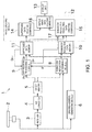
- Fig. 1 is a block diagram illustrating an overall configuration of a radar apparatus 1 according to one embodiment of this disclosure.
- Fig. 2A is a view illustrating an example of display image data generated by the radar apparatus 1 of this embodiment.
- Fig. 2B is a view illustrating an example of a radar image generated by a conventional radar apparatus.
- the radar apparatus 1 of this embodiment is a navigational radar apparatus installed in a ship and used in detecting surrounding thereof (hereinafter, this ship is simply referred to as "the ship").
- the radar apparatus 1 transmits radio waves while rotating a radar antenna (antenna) 2 and creates a radar image based on reflection waves caused by the transmitted radio waves.
- the radar apparatus 1 mainly includes the radar antenna 2, a receiver 3, an A/D converter 4, a sweep memory 5, a drawing address generating module 6, a rain/snow reflection determining module 8, a suppression processing module 9, a rain/snow reflection data memory 10, a suppressed data memory 11, an image creating module 12, and a display unit 13.
- the situation around the ship may also be detected without rotating the radar antenna 2 by using a phased array antenna.
- the radar antenna 2 transmits, while rotating in a horizontal plane at a given rotation cycle, the pulse-shaped radio waves (transmission signals) at a different cycle from the rotation cycle, and receives reflection waves from target object(s).
- the transmission signal is not limited to the pulse-shaped radio wave, and may be a continuous wave.
- the radar antenna 2 is not limited to be a single antenna which performs both the transmission and the reception, and may be divided into an antenna for transmission and an antenna for reception.
- the receiver 3 detects and amplifies the reception signals (the reflection waves caused by the radio waves) obtained by the radar antenna 2, and outputs them to the A/D converter 4.
- the A/D converter 4 receives from the radar antenna 2 the analog signals obtained thereby and converts them into digital signals configured by a plurality of bits.
- the sweep memory 5 stores the AD-converted reception signals (data) for one sweep in real time.
- the sweep memory 5 is configured as a buffer which outputs the reception signals for one sweep, to the suppression processing module 9 and the rain/snow reflection determining module 8 before overwriting them with reception signals obtained by the next transmission.
- the drawing address generating module 6 generates an address indicating on the radar image expressed in an orthogonal coordinate system, a position of a pixel in which the data in the sweep memory 5 is to be drawn, based on an antenna angle with respect to a given direction (e.g., heading). Since the reception signals for one sweep are aligned in a chronological order (in an increasing order of distance from the ship) in the sweep memory 5, the drawing address (X, Y) generated by the drawing address generating module 6 is sequentially generated to shift away from a starting address (X s , Y s ) indicating a position of the ship.
- the drawing address generating module 6 is comprised of one of hardware and software which realizes Equations 1.
- the functions of the drawing address generating module 6 and the rain/snow reflection determining module 8, the suppression processing module 9, and the image creating module 12, which are described later, are achieved by executing programs with an FPGA, a CPU, etc. (not illustrated) provided to the radar apparatus 1.
- X X s + r ⁇ cos ⁇
- Y Y s + r ⁇ sin ⁇
- the rain/snow reflection determining module 8 determines a region from which rain/snow reflection signals among the signals received by the receiver 3 are originated, to be a rain/snow reflection region. For example, the rain/snow reflection determining module 8 (rain/snow region detecting module) determines whether the reception signals include the rain/snow reflection signals (more specifically, a probability of the reception signals being the rain/snow reflection signals) by receiving an antenna azimuth and sequentially calculating a variation in level of the reception signals in the azimuth direction. Specifically, a known method such as that disclosed in JP2010-181335A may be used.
- the suppression processing module 9 of Fig. 1 adjusts (suppresses) levels (echo intensities) of the signals to be reflected in respective pixels of the radar image.
- the suppression processing module 9 of this embodiment calculates a latest processing result (suppression result) Q n obtained by the suppression processing module 9, based on a latest reception signal P n received from the sweep memory 5, a processing result Q n-1 obtained by the suppression processing module 9 at a period of time corresponding to one full antenna rotation before the latest processing result is obtained, which is read from the suppressed data memory 11, and a rain/snow reflection probability ⁇ outputted by a rain/snow probability generating module (not illustrated) which is provided to the rain/snow reflection determining module 8.
- the suppression processing module 9 is comprised of one of hardware and software which executes an operation of Equation 2 described below.
- the processing of executing Equation 2 can be referred to as a scan correlation in which a level of a signal having a low correlation with a previous reception signal received by the receiver 3 is suppressed.
- the level of the signal having the low correlation with the previous reception signal (the signal with low correlation is referred to as "the unnecessary signal"), such as a rain/snow reflection or a water surface reflection, can effectively be suppressed.
- Q n ⁇ ⁇ P n + ⁇ ⁇ Q n ⁇ 1
- the suppression processing module 9 uses the rain/snow reflection probability as one of the coefficients of the scan correlation. Therefore, a value which becomes lower than an actual input value as the rain/snow reflection probability is higher is outputted so that the level of the signal to be reflected on the radar image is suppressed and the rain/snow reflection signal is suppressed corresponding to the rain/snow reflection probability.
- the suppression processing module 9 suppresses the level of the unnecessary signal, such as the rain/snow reflection signal, and adjusts the level of the signal to be reflected in each pixel of the radar image. Since the suppression is performed at the suppression processing module 9, the unnecessary signal is not preferentially and explicitly displayed on the radar image.
- the rain/snow reflection data memory 10 stores information of the rain/snow reflection region acquired by the rain/snow reflection determining module 8, in association with the respective addresses generated by the drawing address generating module 6.
- the suppressed data memory 11 stores data of the suppressed (adjusted) levels (echo intensities) of the signals to be reflected in respective pixels on the radar image by the suppression processing module 9.
- the suppressed data memory 11 stores the processing result Q n obtained by the suppression processing module 9, in association with the address generated by the drawing address generating module 6.
- the image creating module 12 creates display image data for displaying a radar image 90 on the display unit 13 configured by a known liquid crystal display, for example.
- the image creating module 12 mainly includes a suppressed data creating submodule 14, a rain/snow reflection visualizing data creating submodule 15, and a display image data creating submodule 16.
- the suppressed data creating submodule 14 reads the data from the suppressed data memory 11 to acquire the level of each signal suppressed by the suppression processing module 9. Then, based on the suppressed signal level, the suppressed data creating submodule 14 associates each pixel in the region corresponding to the signal, with at least one of color information and luminance information. Thus, the suppressed data creating submodule 14 creates, as the radar image, data indicating a region where the target object (other ship 91, a land 93, etc.) is estimated to exist based on the signal level etc. (target object existing region).
- the suppressed data creating submodule 14 creates, as the radar image, the data (image data) expressing the region where the reflection signal remains after the suppression (target object existing region) with color or luminance corresponding to the echo intensity.
- the suppression-processed radar image created by the suppressed data creating submodule 14 may be, for example, data in a form in which the position of the pixel (address) on the radar image and the color information associated to the pixel are set per pixel.
- the rain/snow reflection visualizing data creating submodule 15 reads the data from the rain/snow reflection data memory 10 and the suppressed data memory 11, and acquires information of an area (i) that is determined to be in the rain/snow reflection region by the rain/snow reflection determining module 8, and (ii) from which the reception signal suppressed in level to below a threshold by the suppression processing module 9 is originated. Specifically, the area satisfying both (i) and (ii) (rain/snow reflection visualized area) is extracted from the region detected by transmitting the radio waves. Further, the rain/snow reflection visualizing data creating submodule 15 creates data for displaying the rain/snow reflection visualized area on the radar image 90 (rain/snow reflection visualizing data).
- the rain/snow reflection visualizing data created by the rain/snow reflection visualizing data creating submodule 15 is data (image data) in which pixels in a non-transparent color (e.g., white) are arrayed in a particular pattern only in a section (area) indicating the rain/snow reflection visualized area (rain/snow reflection visualized area 97).
- a non-transparent color e.g., white
- the rain/snow reflection visualizing data is displayed by being superimposed on the radar image, i.e., superposed on the suppression-processed radar image.
- the rain/snow reflection visualizing data creating submodule 15 creates data indicating a particular pattern of dots, lines, or figures (in this embodiment, a pattern in which white rectangles having a size of 2 ⁇ 2 pixels in vertical and horizontal directions are arranged at a given interval in the vertical and horizontal directions) drawn in the section indicating the rain/snow reflection visualized area 97.
- the rain/snow reflection visualizing data created by the rain/snow reflection visualizing data creating submodule 15 may be, for example, data in a form in which the position of the pixel (address) on the radar image and the color information and luminance information associated to the pixel are set per pixel.
- the display image data creating submodule 16 creates data (display image data) for simultaneously displaying the rain/snow reflection visualized area 97 and the radar image illustrating the target object existing region (land 93 and/or other ship 91), based on the data created by the suppressed data creating submodule 14 and the rain/snow reflection visualizing data creating submodule 15.
- the display image data creating submodule 16 of this embodiment is comprised of a superposing circuit and synthesizes an image signal of the radar image inputted thereto (suppressed data) and an image signal of the rain/snow reflection visualizing data.
- image processing is performed so that the pattern of the rain/snow reflection visualizing data is superimposed on the radar image (i.e., the pattern described above is superposed on the suppressed data).
- the rain/snow reflection visualizing data is data (image data) in which the white rectangles having the size of 2 ⁇ 2 pixels in the vertical and horizontal directions are arranged at the interval in the vertical and horizontal directions only in the section (area) indicating the rain/snow reflection visualized area 97.
- the display image data creating submodule 16 creates the data so that on the radar image, the images illustrating the target objects are (partially) seen through the rain/snow reflection visualized area 97.
- the rain/snow reflection region which is conventionally suppressed in level and substantially cannot be seen is sufficiently displayed without excessively interrupting the images of the target objects, and a user can be provided with useful information.
- the display image data created by the display image data creating submodule 16 is read by a display controlling module (not illustrated) and reflected on a display screen of the display unit 13 as the radar image. Specifically, the display screen of the display unit 13 is raster scanned by the display controlling module, and the display image data created by the display image data creating submodule 16 is read at high speed in synchronization with the raster operation, and the radar image 90 is displayed on the display screen of the display unit 13 with a display color and luminance corresponding to the display image data.
- an area denoted by a reference character "95" in Figs. 2A and 2B is a rain/snow reflection area 95 where signals have intensities above a certain level even after the suppression due to a strong rain force, and is conventionally displayed in a visually recognizable mode (see Fig. 2B ).
- the radar apparatus 1 of this embodiment transmits the radio waves while rotating the radar antenna 2 and generates the radar image 90 based on the reflection waves of the transmitted radio waves.
- the radar apparatus 1 includes the receiver 3, the suppression processing module 9, the rain/snow reflection visualizing data creating submodule 15, and the display image data creating submodule 16.
- the receiver 3 receives the reflection waves of the transmitted radio waves.
- the suppression processing module 9 suppresses the level of each rain/snow reflection signal among the signals received by the receiver 3.
- the rain/snow reflection visualizing data creating submodule 15 creates the data for displaying, as the rain/snow reflection visualized area 97, the area in which the signal level is suppressed to below the threshold by the suppression processing module 9.
- the display image data creating submodule 16 creates the display image data in which the rain/snow reflection visualized area 97 created by the rain/snow reflection visualizing data creating submodule 15 is displayed on the radar image.
- the rain/snow reflection region which conventionally cannot be seen is displayed visualized along with the radar image illustrating the existence of the target objects, and the user can confirm the existence of the rain cloud while also confirming the existence of the target objects on the radar image.
- the rain/snow reflection visualized area 97 Since at least one or some of the land 93, the other ship 91, etc. are (partially) displayed to be seen through the rain/snow reflection visualized area 97 (see Fig. 2A ), it becomes easier to visually grasp that the target objects exist in the rain/snow reflection visualized area 97. Further, since the rain/snow reflection visualized area 97 is superposed on the land 93, the other ship 91, etc. in the dot pattern, even if the region where the target objects exist overlaps with the rain/snow reflection visualized area 97, it becomes easier for the user to find out the existence of both the region and area on the radar image 90.
- the discrimination therebetween becomes easy. Furthermore, by differentiating the display color indicating the rain/snow reflection visualized area 97 from the display color indicating the target object existing region (land 93, other ship 91, etc.) on the radar image 90 as this embodiment, the rain/snow reflection region is discriminated from the target objects on the radar image 90 much more easily. Additionally, by displaying the rain/snow reflection area 95 and the rain/snow reflection visualized area 97 in white, it becomes easy to link with the rain cloud.
- the second embodiment is different from the first embodiment in the data (image data) created by the rain/snow reflection visualizing data creating submodule 15, but otherwise is substantially the same as the first embodiment.
- the rain/snow reflection visualizing data creating submodule 15 reads the data from the rain/snow reflection data memory 10 and the suppressed data memory 11, and acquires information of the area (i) that is determined to be in the rain/snow reflection region by the rain/snow reflection determining module 8, and (ii) from which the reception signal suppressed in level to below a threshold by the suppression processing module 9 is originated. Specifically, the area satisfying both (i) and (ii) (rain/snow reflection visualized area) is extracted from the region detected by transmitting the radio waves. Further, the rain/snow reflection visualizing data creating submodule 15 creates the data for displaying the rain/snow reflection visualized area on the radar image 90.
- the display image data creating submodule 16 creates the data (display image data) for simultaneously displaying the rain/snow reflection visualized area and the radar image including the images indicating the target objects, based on the data created by the suppressed data creating submodule 14 and the rain/snow reflection visualizing data creating submodule 15.
- the display image data creating submodule 16 synthesizes the image signal of the radar image inputted thereto (suppressed data) and the image signal of the rain/snow reflection visualizing data.
- the image processing is performed so that the rain/snow reflection visualizing data (image data) is superimposed (superposed) on the radar image. Therefore, in this embodiment, the display image data creating submodule 16 processes the image data created by the suppressed data creating submodule 14 to partially (only in the rain/snow reflection visualized area 97) be semi-translucent. Even with such a combination of colors, similar effects to those in the first embodiment described above can be obtained.
- the rain/snow reflection visualizing data creating submodule 15 may include a suppression level acquiring submodule 17 configured to acquire a suppressed level S n of each signal in the rain/snow reflection visualized area (a lowered amount of level (echo intensity) by the suppression at the suppression processing module 9) from the suppression processing module 9, and create data of the rain/snow reflection visualized area by differentiating transparency according to the suppressed level S n .
- the suppressed amount of the signal level is easily acquirable by subtracting the suppressed data Q n from the level P n before the suppression at the suppression processing module 9.
- the rain cloud is thicker and the rain or snow is heavier (strong rain/snow reflections are caused) within the area where the display color is whiter and less transparent (the whiteness is emphasized more).
- the rain/snow reflection visualized area 97 is displayed without blocking the images indicating the existence of the target objects. Moreover, in the rain/snow reflection visualized area 97 on the radar image 90, rain/snow reflections are considered to be stronger as the expression of an area is emphasized more (in this embodiment, the expression which reduces the transparency and emphasizes the whiteness). Therefore, the user can estimate from the radar image the heaviness of the rain or snow in the rain/snow reflection areas 95 and 97.
- the suppression processing module 9 suppresses the level of the unnecessary signal, such as the rain/snow reflection signal, by using the scan correlation.
- the method of suppressing the unnecessary signal is not limited to this, and a known FTC (First Time Constant) processing or a CFAR (Constant False Alarm Rate) processing may be used instead. Alternatively, these processings may be combined in use.
- the rain/snow reflection visualized area 97 is expressed by arranging the figures (in the first embodiment, the white rectangles having the size of 2 ⁇ 2 pixels in the vertical and horizontal directions) in the particular pattern and the figures (white rectangles) are displayed by being preferentially superposed on the image indicating the target object existing region (land 93 and/or other ship 91).
- the "figure” here may be other than a rectangle, and may be a dot, a circle, or a polygon.
- the definition of the "figure” broadly includes shapes formed by arranging a plurality of pixels (including lines and dot shapes). Therefore, the definition of the "particular pattern” broadly includes various patterns, such as hatching patterns, diagonal lines, and checkerboard patterns.
- the color information of "white” which is different from the display color indicating the suppressed reflection waves (the display color indicating the target objects, such as the land 93 and the other ship 91) is associated to the pixels configuring the rain/snow reflection visualized area (to be exact, the pixels forming the figure in the rain/snow reflection visualized area).
- the display color is not necessarily be supplied by the rain/snow reflection visualizing data creating submodule 15, and alternatively, the display image data creating submodule 16 may select a display color (color information) different (assign a different color) from the display color indicating the target objects.
- the rain/snow reflection determining module 8 acquires the rain/snow reflection region by sequentially calculating the variation in the azimuth direction, of the reception signal level among the signals received by the receiver 3.
- the variation of the reception signal level may be calculated in the distance direction. In this case, since the rain/snow reflection determination may be performed based on the contents in the sweep memory 5, the processing can be simplified.
- the variation of the reception signal level may be calculated in combination of both the azimuth and distance directions.
- the suppression processing module 9 suppresses, not only the levels of the rain/snow reflection signals, but also the levels of other unnecessary signals (signals which are not to preferentially and explicitly be displayed on the radar image), such as a water surface reflection signal; however, it is not limited to this.
- the suppression processing module 9 may have any configuration as long as it suppresses the rain/snow reflection signal.
- the rain/snow reflection visualizing data creating submodule 15 creates the data for displaying, as the rain/snow reflection visualized area, the area suppressed in signal level to below the threshold by the suppression processing module 9.
- the rain/snow reflection determining module 8 detects the variation of the reception signal level and detects whether the reflection signals are the rain/snow reflection signals based on the variation amount.
- the method of detecting whether the signals are the rain/snow reflection signals is not limited to this, and the rain/snow reflection signals may be detected by a different method.
- the rain/snow reflections are obtained to display the information of rain or snow; however, other reflections may be obtained.
- the "rain” and “snow” described above are merely examples of meteorological phenomena which are detectable according to this disclosure, and this disclosure may be applied to obtain information of any other kind of precipitation including drizzle, graupel, and hail.
Landscapes
- Engineering & Computer Science (AREA)
- Remote Sensing (AREA)
- Radar, Positioning & Navigation (AREA)
- Physics & Mathematics (AREA)
- Computer Networks & Wireless Communication (AREA)
- General Physics & Mathematics (AREA)
- Electromagnetism (AREA)
- Ocean & Marine Engineering (AREA)
- Computer Vision & Pattern Recognition (AREA)
- Radar Systems Or Details Thereof (AREA)
Abstract
Description
- This disclosure relates to a radar apparatus, which displays a signal reflected from rain or snow (rain/snow reflection signal) to be distinguishable from other signals displayed thereon.
- Conventionally, radar apparatuses are known, which are capable of detecting a region where a rain/snow reflection signal is generated, by discriminating the rain/snow reflection signal from a signal obtained from a target object (e.g., a ship or land).
JP2010-181335A - The radar apparatus of
JP2010-181335A - Further, in Paragraph [0052] etc. of
JP2010-181335A JP2010-181335A - However, with the configuration of
JP2010-181335A - The purpose of this disclosure relates to displaying a rain/snow reflection region which is conventionally uneasy or not able to be visually recognized on a radar image since signal levels are suppressed, in a visually recognizable mode along with a radar image illustrating a region where a target object (land, a ship, etc.) is estimated to exist, so that a user can confirm on the radar image, existence of the target object and also rain cloud.
- According to one aspect of this disclosure, a radar apparatus with the following configuration is provided. Specifically, the radar apparatus creates a radar image based on reflection waves caused by radio waves transmitted from an antenna. The radar apparatus includes a receiver, a suppression processing module, a precipitation reflection visualizing data creating module, and a display image data creating module. The receiver receives the reflection waves of the transmitted radio waves, as reception signals. The suppression processing module suppresses levels of reflection signals among the reception signals, each of the reflection signals caused by precipitation. The precipitation reflection visualizing data creating module creates data indicating, as a precipitation reflection visualized area, an area corresponding to the signals of which levels are suppressed to below a threshold by the suppression processing module. The display image data creating module creates display image data indicating on the radar image, the precipitation reflection visualized area created by the precipitation reflection visualizing data creating module.
- Thus, a precipitation reflection region which conventionally cannot be seen can be displayed visualized along with the radar image illustrating existence of a target object (land, a ship, etc.), and the user can confirm existence of rain cloud while also confirming the existence of the target object on the radar image.
- According to another aspect of this disclosure, a radar apparatus with the following configuration is provided. Specifically, the radar apparatus creates a radar image based on reflection waves caused by radio waves transmitted from an antenna. The radar apparatus includes a receiver, a precipitation reflection determining module, a suppression processing module, a precipitation reflection visualizing data creating module, a suppressed data creating module, and a display image data creating module. The receiver receives the reflection waves of the transmitted radio waves, as reception signals. The precipitation reflection determining module determines whether the reception signals include precipitation reflection signals and determines a region where the reflection signals are originated, as a precipitation reflection region. The suppression processing module suppresses levels of the precipitation reflection signals. The precipitation reflection visualizing data creating module creates data indicating, as a precipitation reflection visualized area, an area that is in the precipitation reflection region and corresponding to the signals of which levels are suppressed to below a threshold by the suppression processing module. The suppressed data creating module creates data indicating as the radar image, based on the levels of the precipitation reflection signals. The display image data creating module creates display image data indicating on the radar image, the precipitation reflection visualized area created by the precipitation reflection visualizing data creating module. Here, in the phrase "the signals of which levels are suppressed", the level of each signal indicates an echo intensity of the reception signal.
- Thus, the precipitation reflection region which conventionally cannot be seen on the radar image due to the suppression of the signal level can be displayed along with the radar image illustrating a region where the target object is estimated to exist, and the user can confirm the existence of rain cloud while also confirming the existence of the target object on the radar image. Therefore, a safe navigation can be performed by grasping a marine meteorological situation.
- With the radar apparatus described above, the display image data creating module may create the display image data expressing the precipitation reflection visualized area in a particular pattern formed by arranging figures, the figures being superimposed on the radar image. The "figure" here broadly includes shapes formed by arranging a plurality of pixels, for example, this includes lines and dot shapes. In other words, the "particular pattern" includes various patterns, such as dot patterns, hatching patterns, diagonal lines, and checkerboard patterns.
- Thus, even if the region where the target object is estimated to exist overlaps with the precipitation reflection region, it becomes easier for the user to find out the existence of both the regions on the radar image. Moreover, by displaying the existence of the rain cloud in the mode clearly different from the mode for the existence of the target object, the discrimination therebetween becomes easy.
- With the radar apparatus described above, the display image data creating module may create the display image data expressing the precipitation reflection visualized area as a semi-translucent area, the semi-translucent area being superimposed on the radar image.
- Thus, the precipitation reflection visualized area can be displayed without interrupting the image illustrating the existence of the target object on the radar image.
- With the radar apparatus described above, the display image data creating module may create the display image data indicating the precipitation reflection visualized area in a different color from a color indicating the reception signals other than the precipitation reflection signals on the radar image.
- Thus, the precipitation reflection visualized area can be displayed in a different color from a color indicating the existence of the target object on the radar image, and the precipitation reflection region can be discriminated from the display of the target object much more easily.
- With the radar apparatus described above, the suppression processing module may suppress a level of an unnecessary signal among the reception signals by performing a scan correlation in which a level of a signal having a low correlation with a reception signal received previous thereto by the receiver is suppressed.
- Thus, the level of the unnecessary signal such as the precipitation reflection or a water surface reflection, which has the low correlation with the reception signal received previously, is suppressed so that the unnecessary signal becomes uneasy or not able to be visually confirmed on the radar image. In this manner, the signals reflected on the radar image can be organized and the visual confirmation thereof becomes easy.
- With the radar apparatus described above, the precipitation reflection visualizing data creating module may include a suppressed level acquiring submodule configured to acquire the suppressed level of each of the precipitation reflection signals corresponding to pixels of the precipitation reflection visualized area. The precipitation reflection visualizing data creating module may create the data indicating a position of the precipitation reflection signal in the precipitation reflection visualized area in an emphasized manner as the suppressed amount of the level of the precipitation reflection signal is larger.
- Thus, in the precipitation reflection visualized area on the radar image, it can be considered that the precipitation reflection is stronger in the area displayed more emphasized. The user can visually estimate that the heaviness of rain or snow in the precipitation reflection region.
- The present disclosure is illustrated by way of example and not by way of limitation in the figures of the accompanying drawings, in which like reference numerals indicate like elements and in which:
-
Fig. 1 is a block diagram illustrating an overall configuration of a radar apparatus according to one embodiment of this disclosure; and -
Fig. 2A is a view illustrating an example of display image data generated by the radar apparatus of the embodiment, andFig. 2B is a view illustrating an example of a radar image generated by a conventional radar apparatus. - Embodiments of this disclosure are described with reference to the accompanying drawings. In the following embodiments, an example is illustrated in which this disclosure is applied to a ship. However, the present disclosure may be applied to any kinds of vehicles having a rudder or a similar steering device, such as other watercrafts including boats, vessels, and submarines, as well as land vehicles, airplanes and spaceships.
Fig. 1 is a block diagram illustrating an overall configuration of aradar apparatus 1 according to one embodiment of this disclosure.Fig. 2A is a view illustrating an example of display image data generated by theradar apparatus 1 of this embodiment.Fig. 2B is a view illustrating an example of a radar image generated by a conventional radar apparatus. - The
radar apparatus 1 of this embodiment is a navigational radar apparatus installed in a ship and used in detecting surrounding thereof (hereinafter, this ship is simply referred to as "the ship"). Theradar apparatus 1 transmits radio waves while rotating a radar antenna (antenna) 2 and creates a radar image based on reflection waves caused by the transmitted radio waves. As illustrated inFig. 1 , theradar apparatus 1 mainly includes theradar antenna 2, areceiver 3, an A/D converter 4, asweep memory 5, a drawingaddress generating module 6, a rain/snowreflection determining module 8, asuppression processing module 9, a rain/snowreflection data memory 10, a suppresseddata memory 11, animage creating module 12, and adisplay unit 13. Note that here, an example in which a situation around the ship is detected while rotating theradar antenna 2 is described; however, the situation around the ship may also be detected without rotating theradar antenna 2 by using a phased array antenna. - The
radar antenna 2 transmits, while rotating in a horizontal plane at a given rotation cycle, the pulse-shaped radio waves (transmission signals) at a different cycle from the rotation cycle, and receives reflection waves from target object(s). Note that, the transmission signal is not limited to the pulse-shaped radio wave, and may be a continuous wave. Further, theradar antenna 2 is not limited to be a single antenna which performs both the transmission and the reception, and may be divided into an antenna for transmission and an antenna for reception. - The
receiver 3 detects and amplifies the reception signals (the reflection waves caused by the radio waves) obtained by theradar antenna 2, and outputs them to the A/D converter 4. The A/D converter 4 receives from theradar antenna 2 the analog signals obtained thereby and converts them into digital signals configured by a plurality of bits. - The
sweep memory 5 stores the AD-converted reception signals (data) for one sweep in real time. Thesweep memory 5 is configured as a buffer which outputs the reception signals for one sweep, to thesuppression processing module 9 and the rain/snowreflection determining module 8 before overwriting them with reception signals obtained by the next transmission. - The drawing
address generating module 6 generates an address indicating on the radar image expressed in an orthogonal coordinate system, a position of a pixel in which the data in thesweep memory 5 is to be drawn, based on an antenna angle with respect to a given direction (e.g., heading). Since the reception signals for one sweep are aligned in a chronological order (in an increasing order of distance from the ship) in thesweep memory 5, the drawing address (X, Y) generated by the drawingaddress generating module 6 is sequentially generated to shift away from a starting address (Xs, Ys) indicating a position of the ship. The drawingaddress generating module 6 is comprised of one of hardware and software which realizesEquations 1. The functions of the drawingaddress generating module 6 and the rain/snowreflection determining module 8, thesuppression processing module 9, and theimage creating module 12, which are described later, are achieved by executing programs with an FPGA, a CPU, etc. (not illustrated) provided to theradar apparatus 1.
- X, Y: Address indicating pixel of radar image
- Xs, Ys: Address as origin (starting address)
- r: Distance from sweep origin
- θ: Antenna angle with respect to the given direction
- The rain/snow
reflection determining module 8 determines a region from which rain/snow reflection signals among the signals received by thereceiver 3 are originated, to be a rain/snow reflection region. For example, the rain/snow reflection determining module 8 (rain/snow region detecting module) determines whether the reception signals include the rain/snow reflection signals (more specifically, a probability of the reception signals being the rain/snow reflection signals) by receiving an antenna azimuth and sequentially calculating a variation in level of the reception signals in the azimuth direction. Specifically, a known method such as that disclosed inJP2010-181335A - The
suppression processing module 9 ofFig. 1 adjusts (suppresses) levels (echo intensities) of the signals to be reflected in respective pixels of the radar image. Thesuppression processing module 9 of this embodiment calculates a latest processing result (suppression result) Qn obtained by thesuppression processing module 9, based on a latest reception signal Pn received from thesweep memory 5, a processing result Qn-1 obtained by thesuppression processing module 9 at a period of time corresponding to one full antenna rotation before the latest processing result is obtained, which is read from the suppresseddata memory 11, and a rain/snow reflection probability σ outputted by a rain/snow probability generating module (not illustrated) which is provided to the rain/snowreflection determining module 8. - Specifically, the
suppression processing module 9 is comprised of one of hardware and software which executes an operation ofEquation 2 described below. The processing of executingEquation 2 can be referred to as a scan correlation in which a level of a signal having a low correlation with a previous reception signal received by thereceiver 3 is suppressed. Note that, by suitably determining values of α and β (coefficients of the latest and previous reception signals, respectively), the level of the signal having the low correlation with the previous reception signal (the signal with low correlation is referred to as "the unnecessary signal"), such as a rain/snow reflection or a water surface reflection, can effectively be suppressed.
- α, β: Coefficients determined based on the rain/snow reflection probability σ
- n: Scan number
- As indicated in
Equation 2, thesuppression processing module 9 uses the rain/snow reflection probability as one of the coefficients of the scan correlation. Therefore, a value which becomes lower than an actual input value as the rain/snow reflection probability is higher is outputted so that the level of the signal to be reflected on the radar image is suppressed and the rain/snow reflection signal is suppressed corresponding to the rain/snow reflection probability. Thus, thesuppression processing module 9 suppresses the level of the unnecessary signal, such as the rain/snow reflection signal, and adjusts the level of the signal to be reflected in each pixel of the radar image. Since the suppression is performed at thesuppression processing module 9, the unnecessary signal is not preferentially and explicitly displayed on the radar image. - The rain/snow
reflection data memory 10 stores information of the rain/snow reflection region acquired by the rain/snowreflection determining module 8, in association with the respective addresses generated by the drawingaddress generating module 6. - The suppressed
data memory 11 stores data of the suppressed (adjusted) levels (echo intensities) of the signals to be reflected in respective pixels on the radar image by thesuppression processing module 9. The suppresseddata memory 11 stores the processing result Qn obtained by thesuppression processing module 9, in association with the address generated by the drawingaddress generating module 6. - The
image creating module 12 creates display image data for displaying aradar image 90 on thedisplay unit 13 configured by a known liquid crystal display, for example. Theimage creating module 12 mainly includes a suppresseddata creating submodule 14, a rain/snow reflection visualizingdata creating submodule 15, and a display imagedata creating submodule 16. - The suppressed
data creating submodule 14 reads the data from the suppresseddata memory 11 to acquire the level of each signal suppressed by thesuppression processing module 9. Then, based on the suppressed signal level, the suppresseddata creating submodule 14 associates each pixel in the region corresponding to the signal, with at least one of color information and luminance information. Thus, the suppresseddata creating submodule 14 creates, as the radar image, data indicating a region where the target object (other ship 91, aland 93, etc.) is estimated to exist based on the signal level etc. (target object existing region). - In this embodiment, the suppressed
data creating submodule 14 creates, as the radar image, the data (image data) expressing the region where the reflection signal remains after the suppression (target object existing region) with color or luminance corresponding to the echo intensity. Substantially, the suppression-processed radar image created by the suppresseddata creating submodule 14 may be, for example, data in a form in which the position of the pixel (address) on the radar image and the color information associated to the pixel are set per pixel. - The rain/snow reflection visualizing
data creating submodule 15 reads the data from the rain/snowreflection data memory 10 and the suppresseddata memory 11, and acquires information of an area (i) that is determined to be in the rain/snow reflection region by the rain/snowreflection determining module 8, and (ii) from which the reception signal suppressed in level to below a threshold by thesuppression processing module 9 is originated. Specifically, the area satisfying both (i) and (ii) (rain/snow reflection visualized area) is extracted from the region detected by transmitting the radio waves. Further, the rain/snow reflection visualizingdata creating submodule 15 creates data for displaying the rain/snow reflection visualized area on the radar image 90 (rain/snow reflection visualizing data). In this embodiment, the rain/snow reflection visualizing data created by the rain/snow reflection visualizingdata creating submodule 15 is data (image data) in which pixels in a non-transparent color (e.g., white) are arrayed in a particular pattern only in a section (area) indicating the rain/snow reflection visualized area (rain/snow reflection visualized area 97). - In a post-stage process, the rain/snow reflection visualizing data is displayed by being superimposed on the radar image, i.e., superposed on the suppression-processed radar image. In other words, in this embodiment, the rain/snow reflection visualizing
data creating submodule 15 creates data indicating a particular pattern of dots, lines, or figures (in this embodiment, a pattern in which white rectangles having a size of 2×2 pixels in vertical and horizontal directions are arranged at a given interval in the vertical and horizontal directions) drawn in the section indicating the rain/snow reflection visualizedarea 97. Substantially, the rain/snow reflection visualizing data created by the rain/snow reflection visualizingdata creating submodule 15 may be, for example, data in a form in which the position of the pixel (address) on the radar image and the color information and luminance information associated to the pixel are set per pixel. - The display image
data creating submodule 16 creates data (display image data) for simultaneously displaying the rain/snow reflection visualizedarea 97 and the radar image illustrating the target object existing region (land 93 and/or other ship 91), based on the data created by the suppresseddata creating submodule 14 and the rain/snow reflection visualizingdata creating submodule 15. Specifically, the display imagedata creating submodule 16 of this embodiment is comprised of a superposing circuit and synthesizes an image signal of the radar image inputted thereto (suppressed data) and an image signal of the rain/snow reflection visualizing data. - Note that, in the synthesis of the image by the display image
data creating submodule 16, image processing is performed so that the pattern of the rain/snow reflection visualizing data is superimposed on the radar image (i.e., the pattern described above is superposed on the suppressed data). - In this embodiment, the rain/snow reflection visualizing data is data (image data) in which the white rectangles having the size of 2×2 pixels in the vertical and horizontal directions are arranged at the interval in the vertical and horizontal directions only in the section (area) indicating the rain/snow reflection visualized
area 97. By superposing this on the suppressed data expressed with the color or luminance corresponding to the echo intensity, only part (pixels) of the rain/snow reflection visualizedarea 97 where the white rectangles are disposed is displayed in white, and the radar image (illustrating the existence of the target objects, such as thelands 93 and the other ships 91) is displayed in the part (pixels) between the white rectangles. In other words, it can be said that the display imagedata creating submodule 16 creates the data so that on the radar image, the images illustrating the target objects are (partially) seen through the rain/snow reflection visualizedarea 97. Thus, the rain/snow reflection region which is conventionally suppressed in level and substantially cannot be seen is sufficiently displayed without excessively interrupting the images of the target objects, and a user can be provided with useful information. - The display image data created by the display image
data creating submodule 16 is read by a display controlling module (not illustrated) and reflected on a display screen of thedisplay unit 13 as the radar image. Specifically, the display screen of thedisplay unit 13 is raster scanned by the display controlling module, and the display image data created by the display imagedata creating submodule 16 is read at high speed in synchronization with the raster operation, and theradar image 90 is displayed on the display screen of thedisplay unit 13 with a display color and luminance corresponding to the display image data. Note that, an area denoted by a reference character "95" inFigs. 2A and 2B is a rain/snow reflection area 95 where signals have intensities above a certain level even after the suppression due to a strong rain force, and is conventionally displayed in a visually recognizable mode (seeFig. 2B ). - As described above, the
radar apparatus 1 of this embodiment transmits the radio waves while rotating theradar antenna 2 and generates theradar image 90 based on the reflection waves of the transmitted radio waves. Theradar apparatus 1 includes thereceiver 3, thesuppression processing module 9, the rain/snow reflection visualizingdata creating submodule 15, and the display imagedata creating submodule 16. Thereceiver 3 receives the reflection waves of the transmitted radio waves. Thesuppression processing module 9 suppresses the level of each rain/snow reflection signal among the signals received by thereceiver 3. The rain/snow reflection visualizingdata creating submodule 15 creates the data for displaying, as the rain/snow reflection visualizedarea 97, the area in which the signal level is suppressed to below the threshold by thesuppression processing module 9. The display imagedata creating submodule 16 creates the display image data in which the rain/snow reflection visualizedarea 97 created by the rain/snow reflection visualizingdata creating submodule 15 is displayed on the radar image. - Thus, the rain/snow reflection region which conventionally cannot be seen is displayed visualized along with the radar image illustrating the existence of the target objects, and the user can confirm the existence of the rain cloud while also confirming the existence of the target objects on the radar image.
- Since at least one or some of the
land 93, theother ship 91, etc. are (partially) displayed to be seen through the rain/snow reflection visualized area 97 (seeFig. 2A ), it becomes easier to visually grasp that the target objects exist in the rain/snow reflection visualizedarea 97. Further, since the rain/snow reflection visualizedarea 97 is superposed on theland 93, theother ship 91, etc. in the dot pattern, even if the region where the target objects exist overlaps with the rain/snow reflection visualizedarea 97, it becomes easier for the user to find out the existence of both the region and area on theradar image 90. Moreover, by displaying the existence of the rain cloud in the mode (the pattern in which the rectangles are arrayed, reference character 97) clearly different from the mode for the existence of the target object as this embodiment, the discrimination therebetween becomes easy. Furthermore, by differentiating the display color indicating the rain/snow reflection visualizedarea 97 from the display color indicating the target object existing region (land 93,other ship 91, etc.) on theradar image 90 as this embodiment, the rain/snow reflection region is discriminated from the target objects on theradar image 90 much more easily. Additionally, by displaying the rain/snow reflection area 95 and the rain/snow reflection visualizedarea 97 in white, it becomes easy to link with the rain cloud. - Next, a second embodiment is described. The second embodiment is different from the first embodiment in the data (image data) created by the rain/snow reflection visualizing
data creating submodule 15, but otherwise is substantially the same as the first embodiment. - The rain/snow reflection visualizing
data creating submodule 15 reads the data from the rain/snowreflection data memory 10 and the suppresseddata memory 11, and acquires information of the area (i) that is determined to be in the rain/snow reflection region by the rain/snowreflection determining module 8, and (ii) from which the reception signal suppressed in level to below a threshold by thesuppression processing module 9 is originated. Specifically, the area satisfying both (i) and (ii) (rain/snow reflection visualized area) is extracted from the region detected by transmitting the radio waves. Further, the rain/snow reflection visualizingdata creating submodule 15 creates the data for displaying the rain/snow reflection visualized area on theradar image 90. - The display image
data creating submodule 16 creates the data (display image data) for simultaneously displaying the rain/snow reflection visualized area and the radar image including the images indicating the target objects, based on the data created by the suppresseddata creating submodule 14 and the rain/snow reflection visualizingdata creating submodule 15. - In this embodiment, the display image
data creating submodule 16 synthesizes the image signal of the radar image inputted thereto (suppressed data) and the image signal of the rain/snow reflection visualizing data. - In this synthesis, the image processing is performed so that the rain/snow reflection visualizing data (image data) is superimposed (superposed) on the radar image. Therefore, in this embodiment, the display image
data creating submodule 16 processes the image data created by the suppresseddata creating submodule 14 to partially (only in the rain/snow reflection visualized area 97) be semi-translucent. Even with such a combination of colors, similar effects to those in the first embodiment described above can be obtained. - Note that, the rain/snow reflection visualizing
data creating submodule 15 may include a suppressionlevel acquiring submodule 17 configured to acquire a suppressed level Sn of each signal in the rain/snow reflection visualized area (a lowered amount of level (echo intensity) by the suppression at the suppression processing module 9) from thesuppression processing module 9, and create data of the rain/snow reflection visualized area by differentiating transparency according to the suppressed level Sn. In this case, the suppressed amount of the signal level is easily acquirable by subtracting the suppressed data Qn from the level Pn before the suppression at thesuppression processing module 9. With this configuration, it can be estimated that in the rain/snow reflection visualizedarea 97, the rain cloud is thicker and the rain or snow is heavier (strong rain/snow reflections are caused) within the area where the display color is whiter and less transparent (the whiteness is emphasized more). - By displaying such a display image on the display screen of the
display unit 13, the rain/snow reflection visualizedarea 97 is displayed without blocking the images indicating the existence of the target objects. Moreover, in the rain/snow reflection visualizedarea 97 on theradar image 90, rain/snow reflections are considered to be stronger as the expression of an area is emphasized more (in this embodiment, the expression which reduces the transparency and emphasizes the whiteness). Therefore, the user can estimate from the radar image the heaviness of the rain or snow in the rain/snow reflection areas - Although the embodiments of this disclosure are described above, the above configurations may be modified as follows, for example.
- With the
radar apparatus 1 of the above embodiments, thesuppression processing module 9 suppresses the level of the unnecessary signal, such as the rain/snow reflection signal, by using the scan correlation. However, the method of suppressing the unnecessary signal is not limited to this, and a known FTC (First Time Constant) processing or a CFAR (Constant False Alarm Rate) processing may be used instead. Alternatively, these processings may be combined in use. - With the
radar apparatus 1 of the above embodiments, the rain/snow reflection visualizedarea 97 is expressed by arranging the figures (in the first embodiment, the white rectangles having the size of 2×2 pixels in the vertical and horizontal directions) in the particular pattern and the figures (white rectangles) are displayed by being preferentially superposed on the image indicating the target object existing region (land 93 and/or other ship 91). However, the "figure" here may be other than a rectangle, and may be a dot, a circle, or a polygon. Specifically, the definition of the "figure" broadly includes shapes formed by arranging a plurality of pixels (including lines and dot shapes). Therefore, the definition of the "particular pattern" broadly includes various patterns, such as hatching patterns, diagonal lines, and checkerboard patterns. - With the
radar apparatus 1 of the above embodiments, when the rain/snow reflection visualizing data is created by the rain/snow reflection visualizingdata creating submodule 15, the color information of "white" which is different from the display color indicating the suppressed reflection waves (the display color indicating the target objects, such as theland 93 and the other ship 91) is associated to the pixels configuring the rain/snow reflection visualized area (to be exact, the pixels forming the figure in the rain/snow reflection visualized area). However, the display color is not necessarily be supplied by the rain/snow reflection visualizingdata creating submodule 15, and alternatively, the display imagedata creating submodule 16 may select a display color (color information) different (assign a different color) from the display color indicating the target objects. - In the above embodiments, the rain/snow
reflection determining module 8 acquires the rain/snow reflection region by sequentially calculating the variation in the azimuth direction, of the reception signal level among the signals received by thereceiver 3. However, alternatively, the variation of the reception signal level may be calculated in the distance direction. In this case, since the rain/snow reflection determination may be performed based on the contents in thesweep memory 5, the processing can be simplified. Alternatively, the variation of the reception signal level may be calculated in combination of both the azimuth and distance directions. - With the radar apparatus of the above embodiments, the
suppression processing module 9 suppresses, not only the levels of the rain/snow reflection signals, but also the levels of other unnecessary signals (signals which are not to preferentially and explicitly be displayed on the radar image), such as a water surface reflection signal; however, it is not limited to this. Specifically, thesuppression processing module 9 may have any configuration as long as it suppresses the rain/snow reflection signal. In this case, the rain/snow reflection visualizingdata creating submodule 15 creates the data for displaying, as the rain/snow reflection visualized area, the area suppressed in signal level to below the threshold by thesuppression processing module 9. - With the radar apparatus of the above embodiments, the rain/snow
reflection determining module 8 detects the variation of the reception signal level and detects whether the reflection signals are the rain/snow reflection signals based on the variation amount. However, the method of detecting whether the signals are the rain/snow reflection signals is not limited to this, and the rain/snow reflection signals may be detected by a different method. - With the radar apparatus of the above embodiments, the rain/snow reflections are obtained to display the information of rain or snow; however, other reflections may be obtained. The "rain" and "snow" described above are merely examples of meteorological phenomena which are detectable according to this disclosure, and this disclosure may be applied to obtain information of any other kind of precipitation including drizzle, graupel, and hail.
Claims (7)
- A radar apparatus (1) for creating a radar image based on reflection waves caused by radio waves transmitted from an antenna, comprising:a receiver (3) configured to receive the reflection waves of the transmitted radio waves, as reception signals;a suppression processing module (9) configured to suppress levels of reflection signals among the reception signals, each of the reflection signals caused by precipitation;a precipitation reflection visualizing data creating module (15) configured to create data indicating, as a precipitation reflection visualized area (97), an area corresponding to the signals of which levels are suppressed to below a threshold by the suppression processing module (9); anda display image data creating module (16) configured to create display image data indicating on the radar image, the precipitation reflection visualized area (97) created by the precipitation reflection visualizing data creating module (15).
- A radar apparatus (1) for creating a radar image based on reflection waves caused by radio waves transmitted from an antenna, comprising:a receiver (3) configured to receive the reflection waves of the transmitted radio waves, as reception signals;a precipitation reflection determining module (8) configured to determine whether the reception signals include precipitation reflection signals and determine an area where the reflection signals are originated, as a precipitation reflection area;a suppression processing module (9) configured to suppress levels of the precipitation reflection signals;a precipitation reflection visualizing data creating module (15) configured to create data indicating, as a precipitation reflection visualized area (97), a region that is in the precipitation reflection area and corresponding to the signals of which levels are suppressed to below a threshold by the suppression processing module (9);a suppressed data creating module (14) configured to create data indicating the radar image, based on the levels of the precipitation reflection signals; anda display image data creating module (16) configured to create display image data indicating on the radar image, the precipitation reflection visualized area (97) created by the precipitation reflection visualizing data creating module (15).
- The radar apparatus (1) of claim 1 or 2, wherein the display image data creating module (16) creates the display image data expressing the precipitation reflection visualized area (97) in a particular pattern formed by arranging figures, the figures being superimposed on the radar image.
- The radar apparatus (1) of claim 1 or 2, wherein the display image data creating module (16) creates the display image data expressing the precipitation reflection visualized area (97) as a semi-translucent area, the semi-translucent area being superimposed on the radar image.
- The radar apparatus (1) of any one of claims 1 to 4, wherein the display image data creating module (16) creates the display image data indicating the precipitation reflection visualized area (97) in a different color from a color indicating the reception signals other than the precipitation reflection signals on the radar image.
- The radar apparatus (1) of any one of claims 1 to 5, wherein the suppression processing module (9) suppresses a level of an unnecessary signal among the reception signals by performing a scan correlation in which a level of a signal having a low correlation with a reception signal received previous thereto by the receiver (3) is suppressed.
- The radar apparatus (1) of any one of claims 1 to 6, wherein the precipitation reflection visualizing data creating module (15) includes a suppressed level acquiring submodule (17) configured to acquire the suppressed level of each of the precipitation reflection signals corresponding to pixels of the precipitation reflection visualized area (97), and
wherein the precipitation reflection visualizing data creating module (15) creates the data indicating a position of the precipitation reflection signal in the precipitation reflection visualized area (97) in an emphasized manner as the suppressed amount of the level of the precipitation reflection signal is larger.
Applications Claiming Priority (1)
| Application Number | Priority Date | Filing Date | Title |
|---|---|---|---|
| JP2015183764A JP6526531B2 (en) | 2015-09-17 | 2015-09-17 | Radar equipment |
Publications (1)
| Publication Number | Publication Date |
|---|---|
| EP3144698A1 true EP3144698A1 (en) | 2017-03-22 |
Family
ID=56939968
Family Applications (1)
| Application Number | Title | Priority Date | Filing Date |
|---|---|---|---|
| EP16189301.1A Withdrawn EP3144698A1 (en) | 2015-09-17 | 2016-09-16 | Radar apparatus |
Country Status (4)
| Country | Link |
|---|---|
| US (1) | US10436892B2 (en) |
| EP (1) | EP3144698A1 (en) |
| JP (1) | JP6526531B2 (en) |
| CN (1) | CN106546985B (en) |
Cited By (1)
| Publication number | Priority date | Publication date | Assignee | Title |
|---|---|---|---|---|
| US20160077194A1 (en) * | 2014-09-12 | 2016-03-17 | Furuno Electric Co., Ltd. | Echo display device and cursor movement control method |
Families Citing this family (2)
| Publication number | Priority date | Publication date | Assignee | Title |
|---|---|---|---|---|
| JP7196744B2 (en) * | 2019-04-10 | 2022-12-27 | 株式会社デンソー | radar equipment |
| JP7757067B2 (en) * | 2021-07-14 | 2025-10-21 | 古野電気株式会社 | Target detection device and target detection method |
Citations (4)
| Publication number | Priority date | Publication date | Assignee | Title |
|---|---|---|---|---|
| JP2010181335A (en) | 2009-02-06 | 2010-08-19 | Furuno Electric Co Ltd | Radar device |
| US20110109492A1 (en) * | 2009-11-09 | 2011-05-12 | Masahiro Nakahama | Signal processing device, radar apparatus and signal processing program |
| US20120127019A1 (en) * | 2010-11-19 | 2012-05-24 | Koji Nishiyama | Method and device for detecting target object, and radar apparatus |
| WO2014020995A1 (en) * | 2012-07-31 | 2014-02-06 | 古野電気株式会社 | Meteorological information display system, human navigation device, meteorological information display program and meteorological information display method |
Family Cites Families (9)
| Publication number | Priority date | Publication date | Assignee | Title |
|---|---|---|---|---|
| US3050723A (en) * | 1955-01-04 | 1962-08-21 | Atlas David | Device to discretely characterize levels of signal intensity in radar mapping and computer displays |
| EP1055136B1 (en) * | 1998-02-09 | 2001-11-28 | AlliedSignal Inc. | Aircraft weather information system |
| JP3680265B2 (en) * | 2000-08-24 | 2005-08-10 | 日本無線株式会社 | Radar equipment |
| JP4787400B2 (en) * | 2000-10-11 | 2011-10-05 | 古野電気株式会社 | Detecting device |
| JP5117837B2 (en) * | 2007-12-07 | 2013-01-16 | 株式会社エヌ・ティ・ティ・ドコモ | Wireless communication system, wireless communication method, and base station |
| JP2011002425A (en) * | 2009-06-22 | 2011-01-06 | Furuno Electric Co Ltd | Radar device |
| CN102305930B (en) * | 2011-06-01 | 2013-03-27 | 镇江光宁航海电子科技有限公司 | Method for inhibiting precipitation clutter in radar echo |
| KR20140075881A (en) * | 2012-12-11 | 2014-06-20 | 한국전자통신연구원 | Method for removing target trail |
| CN103744062A (en) * | 2013-12-11 | 2014-04-23 | 上海广电通信技术有限公司 | Radar video multistage multicolor hierarchical display system structure |
-
2015
- 2015-09-17 JP JP2015183764A patent/JP6526531B2/en active Active
-
2016
- 2016-08-22 CN CN201610702273.XA patent/CN106546985B/en active Active
- 2016-09-16 US US15/268,352 patent/US10436892B2/en active Active
- 2016-09-16 EP EP16189301.1A patent/EP3144698A1/en not_active Withdrawn
Patent Citations (5)
| Publication number | Priority date | Publication date | Assignee | Title |
|---|---|---|---|---|
| JP2010181335A (en) | 2009-02-06 | 2010-08-19 | Furuno Electric Co Ltd | Radar device |
| US20110109492A1 (en) * | 2009-11-09 | 2011-05-12 | Masahiro Nakahama | Signal processing device, radar apparatus and signal processing program |
| US20120127019A1 (en) * | 2010-11-19 | 2012-05-24 | Koji Nishiyama | Method and device for detecting target object, and radar apparatus |
| WO2014020995A1 (en) * | 2012-07-31 | 2014-02-06 | 古野電気株式会社 | Meteorological information display system, human navigation device, meteorological information display program and meteorological information display method |
| US20150302622A1 (en) * | 2012-07-31 | 2015-10-22 | Furuno Electric Co., Ltd. | Weather information display system, human navigation device, and method of displaying weather information |
Cited By (2)
| Publication number | Priority date | Publication date | Assignee | Title |
|---|---|---|---|---|
| US20160077194A1 (en) * | 2014-09-12 | 2016-03-17 | Furuno Electric Co., Ltd. | Echo display device and cursor movement control method |
| US9797990B2 (en) * | 2014-09-12 | 2017-10-24 | Furuno Electric Company Limited | Echo display device and cursor movement control method |
Also Published As
| Publication number | Publication date |
|---|---|
| US20170082742A1 (en) | 2017-03-23 |
| JP2017058271A (en) | 2017-03-23 |
| CN106546985A (en) | 2017-03-29 |
| CN106546985B (en) | 2021-11-30 |
| JP6526531B2 (en) | 2019-06-05 |
| US10436892B2 (en) | 2019-10-08 |
Similar Documents
| Publication | Publication Date | Title |
|---|---|---|
| JP5415145B2 (en) | Radar equipment | |
| JP5570786B2 (en) | Signal processing apparatus, radar apparatus, and signal processing program | |
| JP5580621B2 (en) | Echo signal processing device, radar device, echo signal processing method, and echo signal processing program | |
| JP5398195B2 (en) | Radar equipment | |
| EP3144697B1 (en) | Radar apparatus | |
| US20160069987A1 (en) | Method and device for displaying ship vicinity information | |
| CN103675766B (en) | Radar reception device, radar installations and radar return signal display methods | |
| WO2017204075A1 (en) | Signal processing device and radar device | |
| JP6090966B2 (en) | Information display device, radar device, sonar device, and information display method | |
| JP2016206153A (en) | Signal processor and radar device | |
| EP3144698A1 (en) | Radar apparatus | |
| EP2527864A1 (en) | Sensor image display device and method | |
| WO2013084866A1 (en) | Image processing apparatus, radar apparatus, image processing method, and image processing program | |
| EP3006321A1 (en) | Environment information detection device for ships, route setting device, environment information detection method for ships, and program | |
| EP3435112B1 (en) | Radar device and wake display method | |
| JPH03269284A (en) | Three-dimensional display radar | |
| US11221409B2 (en) | Underwater detection apparatus and underwater detection method | |
| JP2011191141A (en) | False image reducing device, radar device, false image reducing method, and false image reducing program | |
| JP3905880B2 (en) | Wave observation device | |
| JP6006750B2 (en) | Signal processing apparatus, radar apparatus, and signal processing method | |
| JP2001141817A (en) | Radar | |
| JP6138430B2 (en) | Dangerous target detection device | |
| JP7231394B2 (en) | Sea level display device and sea level measurement system |
Legal Events
| Date | Code | Title | Description |
|---|---|---|---|
| PUAI | Public reference made under article 153(3) epc to a published international application that has entered the european phase |
Free format text: ORIGINAL CODE: 0009012 |
|
| STAA | Information on the status of an ep patent application or granted ep patent |
Free format text: STATUS: THE APPLICATION HAS BEEN PUBLISHED |
|
| AK | Designated contracting states |
Kind code of ref document: A1 Designated state(s): AL AT BE BG CH CY CZ DE DK EE ES FI FR GB GR HR HU IE IS IT LI LT LU LV MC MK MT NL NO PL PT RO RS SE SI SK SM TR |
|
| AX | Request for extension of the european patent |
Extension state: BA ME |
|
| STAA | Information on the status of an ep patent application or granted ep patent |
Free format text: STATUS: REQUEST FOR EXAMINATION WAS MADE |
|
| 17P | Request for examination filed |
Effective date: 20170919 |
|
| RBV | Designated contracting states (corrected) |
Designated state(s): AL AT BE BG CH CY CZ DE DK EE ES FI FR GB GR HR HU IE IS IT LI LT LU LV MC MK MT NL NO PL PT RO RS SE SI SK SM TR |
|
| STAA | Information on the status of an ep patent application or granted ep patent |
Free format text: STATUS: EXAMINATION IS IN PROGRESS |
|
| 17Q | First examination report despatched |
Effective date: 20190617 |
|
| STAA | Information on the status of an ep patent application or granted ep patent |
Free format text: STATUS: THE APPLICATION IS DEEMED TO BE WITHDRAWN |
|
| 18D | Application deemed to be withdrawn |
Effective date: 20201201 |