EP3144667A1 - Combustion experiment device - Google Patents
Combustion experiment device Download PDFInfo
- Publication number
- EP3144667A1 EP3144667A1 EP15792427.5A EP15792427A EP3144667A1 EP 3144667 A1 EP3144667 A1 EP 3144667A1 EP 15792427 A EP15792427 A EP 15792427A EP 3144667 A1 EP3144667 A1 EP 3144667A1
- Authority
- EP
- European Patent Office
- Prior art keywords
- reaction tube
- gas
- experiment device
- nozzle part
- combustion
- Prior art date
- Legal status (The legal status is an assumption and is not a legal conclusion. Google has not performed a legal analysis and makes no representation as to the accuracy of the status listed.)
- Granted
Links
Images


Classifications
-
- G—PHYSICS
- G01—MEASURING; TESTING
- G01N—INVESTIGATING OR ANALYSING MATERIALS BY DETERMINING THEIR CHEMICAL OR PHYSICAL PROPERTIES
- G01N25/00—Investigating or analyzing materials by the use of thermal means
- G01N25/50—Investigating or analyzing materials by the use of thermal means by investigating flash-point; by investigating explosibility
-
- G—PHYSICS
- G01—MEASURING; TESTING
- G01N—INVESTIGATING OR ANALYSING MATERIALS BY DETERMINING THEIR CHEMICAL OR PHYSICAL PROPERTIES
- G01N25/00—Investigating or analyzing materials by the use of thermal means
- G01N25/50—Investigating or analyzing materials by the use of thermal means by investigating flash-point; by investigating explosibility
- G01N25/52—Investigating or analyzing materials by the use of thermal means by investigating flash-point; by investigating explosibility by determining flash-point of liquids
Definitions
- the present invention relates to a combustion experiment device.
- Patent Document 1 a combustion experiment device is proposed in which a flammable sample fluid flows into a reaction tube to which a temperature gradient in which a temperature increases downstream is imparted, and an ignition temperature, or the like are measured on the basis of a position at which a flame is formed.
- a heater is installed around the reaction tube, and the temperature gradient is imparted to the reaction tube by heating with this heater.
- a temperature that can be given to a reaction tube in the case of heating caused by a heater has an upper limit of about 1000°C. For this reason, when an experiment is performed on combustion characteristics at a higher temperature range, it is considered that the reaction tube is heated by heating the reaction tube from the outside by a flame formed a burner or the like.
- the reaction tube when the reaction tube is heated by the flame formed by the burner or the like, the reaction tube is generally heated from one direction.
- the reaction tube is disposed such that an internal flow passage becomes horizontal, and this reaction tube is heated from below.
- the burner side of the reaction tube has a higher temperature than the opposite side, and a deviation in temperature occurs in the reaction tube in a radial direction.
- the present invention was conceived in view of the aforementioned problems, and an object of the present invention is to prevent deviation in temperature from occurring in a reaction tube in a radial direction of the reaction tube to increase measurement accuracy in a combustion experiment device that imparts a temperature gradient to the reaction tube to measure combustion characteristics of a sample fluid.
- the present invention adopts the following constitutions.
- a first aspect according to the present invention is a combustion experiment device includes: a reaction tube into which a sample fluid flows and to which a temperature gradient in which a temperature rises toward a downstream side is imparted; and a burner part configured to flow a combustible gas along and around the reaction tube from the downstream side to an upstream side of the reaction tube and to maintain a flame surrounding the reaction tube from an outside of the reaction tube in a radial direction.
- a second aspect according to the present invention is configured such that, in the first aspect, the burner part is configured to flow a flammable gas free of a combustion assisting gas as the combustible gas.
- a third aspect according to the present invention is configured such that, in the first or second aspect, the burner part includes:
- a fourth aspect according to the present invention is configured such that, in the third aspect, a plurality of feed tubes are connected to the nozzle part in a circumferential direction of the reaction tube.
- a fifth aspect according to the present invention is configured such that, in the third or fourth aspect, the combustion experiment device includes a partition configured to divide an inside of the feed tube in a radial direction of the feed tube.
- a sixth aspect according to the present invention is configured such that, in any one of the first to fifth aspects, the combustion experiment device includes an auxiliary gas feeder configured to flow an auxiliary gas containing a combustion assisting gas along the reaction tube at an outer side of the reaction tube in the radial direction relative to a region to which the combustible gas flows.
- a seventh aspect according to the present invention is configured such that, in the sixth aspect, an incombustible gas is contained in the auxiliary gas.
- An eighth aspect according to the present invention is configured such that, in the seventh aspect, the combustion experiment device includes a component adjuster configured to adjust a ratio between the combustion assisting gas and the incombustible gas which are contained in the auxiliary gas.
- the flame surrounding the reaction tube from the outside of the reaction tube in the radial direction is formed by the combustible gas that is flowed around the reaction tube from the downstream side toward the upstream side of the reaction tube by the burner part. For this reason, the reaction tube is heated from the outside in the radial direction over an entire area in a circumferential direction by the flame. Therefore, according to the present embodiment, it is possible to prevent a deviation in temperature from occurring within the reaction tube in the radial direction of the reaction tube.
- the combustion experiment device that imparts the temperature gradient to the reaction tube to measure combustion characteristics of the sample fluid, it is possible to prevent the deviation in temperature from occurring within the reaction tube in the radial direction of the reaction tube and improve measurement accuracy. Further, according to the present embodiment, since the reaction tube is heated by a flame formed by the burner part, the temperature of the reaction tube can be raised to a high temperature range that cannot be realized by a heater. For this reason, a sample fluid that shows no reaction until the temperature reaches this high temperature range can be evaluated.
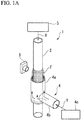
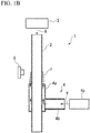
- FIGS. 1A and 1B are schematic views showing a combustion experiment device 1 of the present embodiment wherein FIG. 1A is a perspective view and FIG. 1B is a longitudinal sectional view.
- the combustion experiment device 1 is provided with a reaction tube 2, a sample evaluation gas feeder 3, a burner part 4, and a camera 5.
- the reaction tube 2 is a linear tube disposed by a support (not shown) such that an axial direction (a flow direction) thereof is parallel to a vertical direction.
- This reaction tube 2 is formed of a material (e.g. quartz glass) transparent to light emitted from a flame formed therein.
- a temperature gradient in which a temperature is raised toward a downstream side (a lower side in FIG. 1A and 1B ) by the burner part 4 is imparted, and a sample evaluation gas (a sample fluid) X is fed from an upstream side (an upper side in FIG. 1A and 1B ) by the sample evaluation gas feeder 3.
- An internal flow passage of this reaction tube 2 is set to a diameter smaller than that of a quenching diameter at room temperature.
- a cross-sectional area of the flow passage is required to extend to some degree.
- the aforementioned quenching diameter refers to a diameter providing a cross-sectional area in which a formed flame cannot be spread.
- the sample evaluation gas feeder 3 is connected to an upper end of the reaction tube 2 and feeds the sample evaluation gas X from the upper end toward a lower end of the reaction tube 2.
- This sample evaluation gas feeder 3 feeds a mixed gas in which a fuel and an oxidant are mixed and which acts as the sample evaluation gas X to the reaction tube 2.
- the burner part 4 is provided with a nozzle part 4a, a feed tube 4b, and a hydrogen gas feeder 4c.
- the nozzle part 4a is a cylindrical part that covers the reaction tube 2 from the outside of the reaction tube 2 in a radial direction.
- the nozzle part 4a has an upper end acting as an opened end and a lower end acting as a closed end.
- the nozzle part 4a having this constitution ejects a combustible gas Y toward the upstream side (the upper side) of the reaction tube 2. That is, the burner part 4 flows the combustible gas Y along and around the reaction tube 2 from the downstream side toward the upstream side of the reaction tube 2.
- FIG. 2A is a cross-sectional view of the nozzle part 4a and the reaction tube 2.
- the nozzle part 4a is a circular tube disposed to be coaxial with respect to an axis L of the reaction tube 2.
- an annular flow passage R1 having a uniform size in a circumferential direction is formed between the reaction tube 2 and the nozzle part 4a. For this reason, the combustible gas Y passing through this annular flow passage R1 to be injected from the upper end of the nozzle part 4a is uniformly injected around the reaction tube 2 when viewed in a direction running along the axis L of the reaction tube 2.
- the feed tube 4b is a tube that is connected to the nozzle part 4a from the outside of the nozzle part 4a in the radial direction and is intended to feed the combustible gas Y to the inside of the nozzle part 4a.
- FIG. 2B is a cross-sectional view of the feed tube 4b. As shown in this figure, the inside of the feed tube 4b is provided with a flow passage R2 guiding the combustible gas Y. A cross-sectional area of this flow passage R2 is set to be greater than that of the annular flow passage R1 shown in FIG. 2A .
- an inlet area of the nozzle part 4a for the combustible gas Y is greater than an outlet area, and the combustible gas Y is easily uniformly distributed in the nozzle part 4a. Therefore, the combustible gas Y can be more uniformly injected around the reaction tube 2.
- the hydrogen gas feeder 4c feeds hydrogen gas acting as the combustible gas Y to the feed tube 4b.
- the hydrogen gas that is a flammable gas is used as the combustible gas Y. That is, a combustion assisting gas such as oxygen is not contained in the combustible gas Y.
- This burner part 4 feeds the hydrogen gas acting as the combustible gas Y from the hydrogen gas feeder 4c to the nozzle part 4a through the feed tube 4b, and flows the combustible gas Y from the nozzle part 4a around the reaction tube 2. In this way, the burner part 4 continues to flow the combustible gas Y, thereby maintaining a flame F to be described below.
- the camera 5 is supported and disposed beside the reaction tube 2 by a support (not shown) and images a flame formed within the reaction tube 2 from the outside of the reaction tube 2, thereby obtaining information about a position of the flame in the reaction tube 2. Since a quantity of emitted light of the flame formed within the reaction tube 2 is small, the camera 5 preferably sets a long exposure time as needed to capture an image.
- the combustible gas Y is fed from the hydrogen gas feeder 4c to the nozzle part 4a through the feed tube 4b, and this combustible gas Y is ejected from the upper end of the nozzle part 4a surrounding the reaction tube 2. That is, the combustible gas Y flows along and around the reaction tube 2 from the downstream side toward the upstream side of the reaction tube 2 by means of the burner part 4.
- the flame F that, as shown in FIGS. 1A and 1B , surrounds the reaction tube 2 from the outside in the radial direction and is tapered toward the upper end of the reaction tube 2 is formed.
- This flame F is maintained as the combustible gas Y is continuously fed from the burner part 4.
- the combustible gas Y ejected from the nozzle part 4a is used as the hydrogen gas that is a flammable gas free of a combustion assisting gas.
- the flame F is a diffusion flame formed by diffusion combustion in which hydrogen gas is burnt by oxygen which is fed from the outside of the flame F.
- the flame F When the flame F is formed in this way, a temperature gradient in which a temperature becomes high at a position at which the flame F is formed and becomes low toward the upstream side (the upper side) of the reaction tube 2 is imparted to the reaction tube 2.
- the sample evaluation gas X is fed from the upstream side to the reaction tube 2 to which this temperature gradient is imparted by the sample evaluation gas feeder 3.
- the sample evaluation gas X fed to the reaction tube 2 is raised in temperature as it approaches the downstream side of the reaction tube 2, and is ignited at a place exceeding a given temperature.
- the flame is formed inside the reaction tube 2.
- the flame formed inside this reaction tube 2 is imaged by the camera 5, and an ignition temperature of the sample evaluation gas X is found from the position of the imaged flame and information about the temperature gradient imparted to the reaction tube 2.
- the combustion experiment device 1 of the present embodiment As described above, the combustible gas Y flows around the reaction tube 2 from the downstream side toward the upstream side of the reaction tube 2 by means of the burner part 4. Thereby, the flame F surrounding the reaction tube 2 from the outside in the radial direction is formed. For this reason, the reaction tube 2 is heated from the outside in the radial direction over an entire area in a circumferential direction by the flame F. Therefore, according to the combustion experiment device 1 of the present embodiment, it is possible to prevent a deviation in temperature from occurring within the reaction tube 2 in the radial direction of the reaction tube 2. Consequently, according to the combustion experiment device 1 of the present embodiment, it is possible to prevent the deviation in temperature from occurring within the reaction tube 2 in the radial direction of the reaction tube 2 and to improve measurement accuracy.
- the burner part 4 flows the hydrogen gas that acts as the combustible gas Y and is the flammable gas free of a combustion assisting gas. For this reason, the flame F becomes the diffusion flame. Thus, it is possible to prevent the flame from intruding into the nozzle part 4a. Therefore, the combustion experiment device 1 is, for example, disposed in a pressurized container, and an experiment may be performed under high pressure.
- the burner part 4 is provided with the nozzle part 4a that covers the reaction tube 2 from the outside in the radial direction and ejects the combustible gas Y, and the feed tube 4b that is connected to the nozzle part 4a and feeds the combustible gas Y to the nozzle part 4a.
- the combustible gas Y can be fed around the reaction tube 2 with a simple constitution.
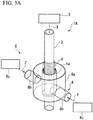
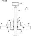
- FIGS. 3A and 3B are schematic views showing the whole of a combustion experiment device 1A of the present embodiment wherein FIG. 3A is a perspective view, and FIG. 3B is a longitudinal sectional view. As shown in these figures, the combustion experiment device 1A of the present embodiment is provided with an auxiliary gas feeder 6.
- This auxiliary gas feeder 6 is provided with a nozzle part 6a, a feed tube 6b, and an air feeder 6c.
- the nozzle part 6a is a cylindrical part that covers a nozzle part 4a of a burner part 4 from the outside of a reaction tube 2 in a radial direction.
- the nozzle part 6a has an upper end acting as an opened end and a lower end acting as a closed end.
- the nozzle part 6a having this constitution ejects an auxiliary gas Z toward an upstream side (an upper side) of the reaction tube 2. That is, the auxiliary gas feeder 6 flows the auxiliary gas along the reaction tube 2 at the outside of the reaction tube 2 in the radial direction relative to a region to which a combustible gas Y flows.
- the nozzle part 6a is a circular tube disposed to be coaxial with respect to an axis L of the reaction tube 2.
- an annular flow passage having a uniform size in a circumferential direction is formed between the nozzle part 6a of the auxiliary gas feeder 6 and the nozzle part 4a of the burner part 4.
- the auxiliary gas Z passing through this annular flow passage to be injected from the upper end of the nozzle part 6a is uniformly injected around the reaction tube 2 when viewed in a direction running along the axis L of the reaction tube 2.
- the feed tube 6b is a tube that is connected to the nozzle part 6a from the outside of the nozzle part 6a in a radial direction and is intended to feed the auxiliary gas Z to the inside of the nozzle part 6a.
- a cross-sectional area of the feed tube 6b is set to be greater than that of the annular flow passage formed between the nozzle part 6a of the auxiliary gas feeder 6 and the nozzle part 4a of the burner part 4.
- an inlet area of the nozzle part 6a for the auxiliary gas Z is greater than an outlet area, and the auxiliary gas Z is easily uniformly distributed in the nozzle part 6a. Therefore, the auxiliary gas Z can be more uniformly injected around the reaction tube 2.
- the air feeder 6c feeds air acting as the auxiliary gas Z to the feed tube 6b.
- a gas that contains a combustion assisting gas, such as oxygen, and an incombustible gas may be used.
- air is used as a typical example.
- This auxiliary gas feeder 6 feeds the air acting as the auxiliary gas Z from the air feeder 6c to the nozzle part 6a through the feed tube 6b, and flows the auxiliary gas Z from the nozzle part 6a around the reaction tube 2.
- a flow of the auxiliary gas Z directed toward the upstream side of the reaction tube 2 is formed around a flame F, and the flame F elongates toward the upstream side of the reaction tube 2.
- a concentration of the incombustible gas such as nitrogen in the auxiliary gas Z is changed, a spreading and a length of the flame F can be adjusted.
- the air feeder 6c may be given a function of a component adjusting part that adjusts the ratio between the combustion assisting gas and the incombustible gas.
- the shape of the flame F can be arbitrarily modified.
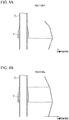
- FIG. 4A is a schematic view showing a temperature gradient imparted to the reaction tube 2 in the combustion experiment device 1 of the first embodiment.
- FIG. 4B is a schematic view showing a temperature gradient imparted to the reaction tube 2 in the combustion experiment device 1A of the present embodiment.
- the temperature gradient imparted to the reaction tube 2 is smoothed, and an amount of variation in temperature is reduced with respect to an amount of variation in position of the reaction tube 2. For this reason, information about a temperature corresponding to a position of the flame formed inside the reaction tube 2 can be obtained with higher accuracy, and measurement accuracy can be improved.
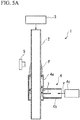
- a partition 7 dividing the inside of the feed tube 4b in the radial direction of the feed tube 4b may be installed in the feed tube 4b of the burner part 4.
- a constitution in which a plurality of feed tubes 4b are connected to the nozzle part 4a from respective sides in the circumferential direction of the reaction tube 2 may be adopted. Even in this case, since the combustible gas Y is dispersed and fed to the nozzle part 4a of the burner part 4, the combustible gas Y can be more uniformly ejected from the nozzle part 4a.
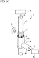
- a dispersion plate 8 having a plurality of through-holes may be installed at the upper end used as the opened end of the nozzle part 4a. Even in this case, the combustible gas Y can be more uniformly ejected from the nozzle part 4a.
- the constitutions shown in FIGS. 5A to 5C may be equally applied to the auxiliary gas feeder 6 of the second embodiment. That is, a constitution in which the partition 7 is installed in the feed tube 6b, a constitution in which a plurality of feed tubes 6b are connected to the nozzle part 6a, and a constitution in which the dispersion plate 8 is installed on the nozzle part 6a may be adopted by the auxiliary gas feeder 6 of the second embodiment.
- the constitution in which a flammable gas free of a combustion assisting gas is used as the combustible gas Y is adopted.
- a flammable gas i.e. a premixed gas
- a combustion assisting gas may be used as the combustible gas Y.
- countermeasures which provide a cooling mechanism at the upper end of the nozzle part 4a or sufficiently increase a flow rate of the combustible gas Y ejected from the nozzle part 4a are preferably taken.
- the flammable gas is not limited to the hydrogen gas.
- the present invention is not limited to this.
- the feed tube 4b may be connected to the nozzle part 4a in the axial direction of the reaction tube 2, and the combustible gas Y may be fed to the nozzle part 4a in the axial direction.
- the hydrogen gas feeder 4c is exposed to an exhaust gas exhausted from the lower end of the reaction tube 2.
- the reaction tube 2 is disposed such that the axial direction thereof becomes the vertical direction and the sample evaluation gas X is fed from the upper end side of the reaction tube 2 has been described.
- the present invention is not limited to this.
- a constitution in which the sample evaluation gas X is fed from the lower end side of the reaction tube 2 may be adopted.
- the burner part 4 is disposed to eject the flammable gas downward.
Landscapes
- Physics & Mathematics (AREA)
- Health & Medical Sciences (AREA)
- Life Sciences & Earth Sciences (AREA)
- Chemical & Material Sciences (AREA)
- Analytical Chemistry (AREA)
- Biochemistry (AREA)
- General Health & Medical Sciences (AREA)
- General Physics & Mathematics (AREA)
- Immunology (AREA)
- Pathology (AREA)
- Investigating Or Analyzing Materials Using Thermal Means (AREA)
Abstract
Description
- The present invention relates to a combustion experiment device.
- Priority is claimed on Japanese Patent Application No.
2014-99863, filed on May 13, 2014 - In recent years, as shown in, for example, Patent Document 1, a combustion experiment device is proposed in which a flammable sample fluid flows into a reaction tube to which a temperature gradient in which a temperature increases downstream is imparted, and an ignition temperature, or the like are measured on the basis of a position at which a flame is formed. For example, in Patent Document 1, a heater is installed around the reaction tube, and the temperature gradient is imparted to the reaction tube by heating with this heater.
- Japanese Unexamined Patent Application, First Publication No.
2012-108036 - Meanwhile, a temperature that can be given to a reaction tube in the case of heating caused by a heater has an upper limit of about 1000°C. For this reason, when an experiment is performed on combustion characteristics at a higher temperature range, it is considered that the reaction tube is heated by heating the reaction tube from the outside by a flame formed a burner or the like.
- However, when the reaction tube is heated by the flame formed by the burner or the like, the reaction tube is generally heated from one direction. For example, the reaction tube is disposed such that an internal flow passage becomes horizontal, and this reaction tube is heated from below. For this reason, the burner side of the reaction tube has a higher temperature than the opposite side, and a deviation in temperature occurs in the reaction tube in a radial direction.
- To accurately measure an ignition temperature, or the like of a sample fluid, it is necessary to know what kind of temperature gradient is imparted to the reaction tube in advance. However, as described above, if the deviation in temperature occurs in the radial direction of the reaction tube, a difference between data of a pre-stored temperature gradient and the actual temperature occurs. For this reason, a slight deviation occurs in a relation between a flame position in the reaction tube and an actual temperature of the reaction tube, and measurement accuracy is reduced.
- The present invention was conceived in view of the aforementioned problems, and an object of the present invention is to prevent deviation in temperature from occurring in a reaction tube in a radial direction of the reaction tube to increase measurement accuracy in a combustion experiment device that imparts a temperature gradient to the reaction tube to measure combustion characteristics of a sample fluid.
- As means for solving the above problems, the present invention adopts the following constitutions.
- A first aspect according to the present invention is a combustion experiment device includes: a reaction tube into which a sample fluid flows and to which a temperature gradient in which a temperature rises toward a downstream side is imparted; and a burner part configured to flow a combustible gas along and around the reaction tube from the downstream side to an upstream side of the reaction tube and to maintain a flame surrounding the reaction tube from an outside of the reaction tube in a radial direction.
- A second aspect according to the present invention is configured such that, in the first aspect, the burner part is configured to flow a flammable gas free of a combustion assisting gas as the combustible gas.
- A third aspect according to the present invention is configured such that, in the first or second aspect, the burner part includes:
- a nozzle part which covers the reaction tube from the outside of the reaction tube in the radial direction and configured to eject the combustible gas; and a feed tube connected to the nozzle part and configured to feed the combustible gas to the nozzle part.
- A fourth aspect according to the present invention is configured such that, in the third aspect, a plurality of feed tubes are connected to the nozzle part in a circumferential direction of the reaction tube.
- A fifth aspect according to the present invention is configured such that, in the third or fourth aspect, the combustion experiment device includes a partition configured to divide an inside of the feed tube in a radial direction of the feed tube.
- A sixth aspect according to the present invention is configured such that, in any one of the first to fifth aspects, the combustion experiment device includes an auxiliary gas feeder configured to flow an auxiliary gas containing a combustion assisting gas along the reaction tube at an outer side of the reaction tube in the radial direction relative to a region to which the combustible gas flows.
- A seventh aspect according to the present invention is configured such that, in the sixth aspect, an incombustible gas is contained in the auxiliary gas.
- An eighth aspect according to the present invention is configured such that, in the seventh aspect, the combustion experiment device includes a component adjuster configured to adjust a ratio between the combustion assisting gas and the incombustible gas which are contained in the auxiliary gas.
- According to the present invention, the flame surrounding the reaction tube from the outside of the reaction tube in the radial direction is formed by the combustible gas that is flowed around the reaction tube from the downstream side toward the upstream side of the reaction tube by the burner part. For this reason, the reaction tube is heated from the outside in the radial direction over an entire area in a circumferential direction by the flame. Therefore, according to the present embodiment, it is possible to prevent a deviation in temperature from occurring within the reaction tube in the radial direction of the reaction tube. Consequently, according to the present embodiment, in the combustion experiment device that imparts the temperature gradient to the reaction tube to measure combustion characteristics of the sample fluid, it is possible to prevent the deviation in temperature from occurring within the reaction tube in the radial direction of the reaction tube and improve measurement accuracy. Further, according to the present embodiment, since the reaction tube is heated by a flame formed by the burner part, the temperature of the reaction tube can be raised to a high temperature range that cannot be realized by a heater. For this reason, a sample fluid that shows no reaction until the temperature reaches this high temperature range can be evaluated.
-
-
FIG. 1A is a perspective view schematically showing an overall constitution of a combustion experiment device in a first embodiment of the present invention. -
FIG. 1B is a longitudinal sectional view schematically showing the overall constitution of the combustion experiment device in the first embodiment of the present invention. -
FIG. 2A is a cross-sectional view including a reaction tube and a nozzle part provided for the combustion experiment device in the first embodiment of the present invention. -
FIG. 2B is a cross-sectional view including a feed tube provided for the combustion experiment device in the first embodiment of the present invention. -
FIG. 3A is a perspective view schematically showing an overall constitution of a combustion experiment device in a second embodiment of the present invention. -
FIG. 3B is a longitudinal sectional view schematically showing the overall constitution of the combustion experiment device in the second embodiment of the present invention. -
FIG. 4A is a schematic view showing a temperature gradient imparted to the reaction tube in the combustion experiment device in the first embodiment of the present invention. -
FIG. 4B is a schematic view showing a temperature gradient imparted to a reaction tube in the combustion experiment device in the second embodiment of the present invention. -
FIG. 5A is a longitudinal sectional view of a first modification of the combustion experiment device in the first embodiment of the present invention. -
FIG. 5B is a perspective view of a second modification of the combustion experiment device in the first embodiment of the present invention. -
FIG. 5C is a perspective view of a third modification of the combustion experiment device in the first embodiment of the present invention. - Hereinafter, embodiments of a combustion experiment device according to the present invention will be described with reference to the drawings. In the drawings below, the scale of each member is adequately changed to have each member be a recognizable size.
-
FIGS. 1A and1B are schematic views showing a combustion experiment device 1 of the present embodiment whereinFIG. 1A is a perspective view andFIG. 1B is a longitudinal sectional view. As shown in these figures, the combustion experiment device 1 is provided with areaction tube 2, a sample evaluation gas feeder 3, a burner part 4, and acamera 5. - The
reaction tube 2 is a linear tube disposed by a support (not shown) such that an axial direction (a flow direction) thereof is parallel to a vertical direction. Thisreaction tube 2 is formed of a material (e.g. quartz glass) transparent to light emitted from a flame formed therein. In thisreaction tube 2, a temperature gradient in which a temperature is raised toward a downstream side (a lower side inFIG. 1A and1B ) by the burner part 4 is imparted, and a sample evaluation gas (a sample fluid) X is fed from an upstream side (an upper side inFIG. 1A and1B ) by the sample evaluation gas feeder 3. - An internal flow passage of this
reaction tube 2 is set to a diameter smaller than that of a quenching diameter at room temperature. To spread a flame within the flow passage, a cross-sectional area of the flow passage is required to extend to some degree. When the flow passage cross-sectional area is small, a flame is not spread. Here, the aforementioned quenching diameter refers to a diameter providing a cross-sectional area in which a formed flame cannot be spread. - The sample evaluation gas feeder 3 is connected to an upper end of the
reaction tube 2 and feeds the sample evaluation gas X from the upper end toward a lower end of thereaction tube 2. This sample evaluation gas feeder 3 feeds a mixed gas in which a fuel and an oxidant are mixed and which acts as the sample evaluation gas X to thereaction tube 2. - The burner part 4 is provided with a
nozzle part 4a, afeed tube 4b, and ahydrogen gas feeder 4c. Thenozzle part 4a is a cylindrical part that covers thereaction tube 2 from the outside of thereaction tube 2 in a radial direction. Thenozzle part 4a has an upper end acting as an opened end and a lower end acting as a closed end. Thenozzle part 4a having this constitution ejects a combustible gas Y toward the upstream side (the upper side) of thereaction tube 2. That is, the burner part 4 flows the combustible gas Y along and around thereaction tube 2 from the downstream side toward the upstream side of thereaction tube 2. -
FIG. 2A is a cross-sectional view of thenozzle part 4a and thereaction tube 2. As shown in this figure, thenozzle part 4a is a circular tube disposed to be coaxial with respect to an axis L of thereaction tube 2. Thus, an annular flow passage R1 having a uniform size in a circumferential direction is formed between thereaction tube 2 and thenozzle part 4a. For this reason, the combustible gas Y passing through this annular flow passage R1 to be injected from the upper end of thenozzle part 4a is uniformly injected around thereaction tube 2 when viewed in a direction running along the axis L of thereaction tube 2. - The
feed tube 4b is a tube that is connected to thenozzle part 4a from the outside of thenozzle part 4a in the radial direction and is intended to feed the combustible gas Y to the inside of thenozzle part 4a.FIG. 2B is a cross-sectional view of thefeed tube 4b. As shown in this figure, the inside of thefeed tube 4b is provided with a flow passage R2 guiding the combustible gas Y. A cross-sectional area of this flow passage R2 is set to be greater than that of the annular flow passage R1 shown inFIG. 2A . Thus, an inlet area of thenozzle part 4a for the combustible gas Y is greater than an outlet area, and the combustible gas Y is easily uniformly distributed in thenozzle part 4a. Therefore, the combustible gas Y can be more uniformly injected around thereaction tube 2. - The
hydrogen gas feeder 4c feeds hydrogen gas acting as the combustible gas Y to thefeed tube 4b. For this reason, in the present embodiment, the hydrogen gas that is a flammable gas is used as the combustible gas Y. That is, a combustion assisting gas such as oxygen is not contained in the combustible gas Y. - This burner part 4 feeds the hydrogen gas acting as the combustible gas Y from the
hydrogen gas feeder 4c to thenozzle part 4a through thefeed tube 4b, and flows the combustible gas Y from thenozzle part 4a around thereaction tube 2. In this way, the burner part 4 continues to flow the combustible gas Y, thereby maintaining a flame F to be described below. - The
camera 5 is supported and disposed beside thereaction tube 2 by a support (not shown) and images a flame formed within thereaction tube 2 from the outside of thereaction tube 2, thereby obtaining information about a position of the flame in thereaction tube 2. Since a quantity of emitted light of the flame formed within thereaction tube 2 is small, thecamera 5 preferably sets a long exposure time as needed to capture an image. - In this combustion experiment device 1 of the present embodiment, the combustible gas Y is fed from the
hydrogen gas feeder 4c to thenozzle part 4a through thefeed tube 4b, and this combustible gas Y is ejected from the upper end of thenozzle part 4a surrounding thereaction tube 2. That is, the combustible gas Y flows along and around thereaction tube 2 from the downstream side toward the upstream side of thereaction tube 2 by means of the burner part 4. - In this state, when the combustible gas Y ejected from the
nozzle part 4a is ignited by an igniter (not shown), the flame F that, as shown inFIGS. 1A and1B , surrounds thereaction tube 2 from the outside in the radial direction and is tapered toward the upper end of thereaction tube 2 is formed. This flame F is maintained as the combustible gas Y is continuously fed from the burner part 4. Here, in the present embodiment, the combustible gas Y ejected from thenozzle part 4a is used as the hydrogen gas that is a flammable gas free of a combustion assisting gas. For this reason, the flame F is a diffusion flame formed by diffusion combustion in which hydrogen gas is burnt by oxygen which is fed from the outside of the flame F. - When the flame F is formed in this way, a temperature gradient in which a temperature becomes high at a position at which the flame F is formed and becomes low toward the upstream side (the upper side) of the
reaction tube 2 is imparted to thereaction tube 2. The sample evaluation gas X is fed from the upstream side to thereaction tube 2 to which this temperature gradient is imparted by the sample evaluation gas feeder 3. The sample evaluation gas X fed to thereaction tube 2 is raised in temperature as it approaches the downstream side of thereaction tube 2, and is ignited at a place exceeding a given temperature. Thus, the flame is formed inside thereaction tube 2. Then, the flame formed inside thisreaction tube 2 is imaged by thecamera 5, and an ignition temperature of the sample evaluation gas X is found from the position of the imaged flame and information about the temperature gradient imparted to thereaction tube 2. - According to the combustion experiment device 1 of the present embodiment as described above, the combustible gas Y flows around the
reaction tube 2 from the downstream side toward the upstream side of thereaction tube 2 by means of the burner part 4. Thereby, the flame F surrounding thereaction tube 2 from the outside in the radial direction is formed. For this reason, thereaction tube 2 is heated from the outside in the radial direction over an entire area in a circumferential direction by the flame F. Therefore, according to the combustion experiment device 1 of the present embodiment, it is possible to prevent a deviation in temperature from occurring within thereaction tube 2 in the radial direction of thereaction tube 2. Consequently, according to the combustion experiment device 1 of the present embodiment, it is possible to prevent the deviation in temperature from occurring within thereaction tube 2 in the radial direction of thereaction tube 2 and to improve measurement accuracy. - In the combustion experiment device 1 of the present embodiment, the burner part 4 flows the hydrogen gas that acts as the combustible gas Y and is the flammable gas free of a combustion assisting gas. For this reason, the flame F becomes the diffusion flame. Thus, it is possible to prevent the flame from intruding into the
nozzle part 4a. Therefore, the combustion experiment device 1 is, for example, disposed in a pressurized container, and an experiment may be performed under high pressure. - In the combustion experiment device 1 of the present embodiment, the burner part 4 is provided with the
nozzle part 4a that covers thereaction tube 2 from the outside in the radial direction and ejects the combustible gas Y, and thefeed tube 4b that is connected to thenozzle part 4a and feeds the combustible gas Y to thenozzle part 4a. For this reason, the combustible gas Y can be fed around thereaction tube 2 with a simple constitution. - Next, a second embodiment of the present embodiment will be described. In the description of the present embodiment, a description of the same parts as in the first embodiment will be omitted or simplified.
-
FIGS. 3A and3B are schematic views showing the whole of acombustion experiment device 1A of the present embodiment whereinFIG. 3A is a perspective view, andFIG. 3B is a longitudinal sectional view. As shown in these figures, thecombustion experiment device 1A of the present embodiment is provided with anauxiliary gas feeder 6. - This
auxiliary gas feeder 6 is provided with anozzle part 6a, afeed tube 6b, and anair feeder 6c. Thenozzle part 6a is a cylindrical part that covers anozzle part 4a of a burner part 4 from the outside of areaction tube 2 in a radial direction. Thenozzle part 6a has an upper end acting as an opened end and a lower end acting as a closed end. Thenozzle part 6a having this constitution ejects an auxiliary gas Z toward an upstream side (an upper side) of thereaction tube 2. That is, theauxiliary gas feeder 6 flows the auxiliary gas along thereaction tube 2 at the outside of thereaction tube 2 in the radial direction relative to a region to which a combustible gas Y flows. - The
nozzle part 6a is a circular tube disposed to be coaxial with respect to an axis L of thereaction tube 2. Thus, an annular flow passage having a uniform size in a circumferential direction is formed between thenozzle part 6a of theauxiliary gas feeder 6 and thenozzle part 4a of the burner part 4. For this reason, the auxiliary gas Z passing through this annular flow passage to be injected from the upper end of thenozzle part 6a is uniformly injected around thereaction tube 2 when viewed in a direction running along the axis L of thereaction tube 2. - The
feed tube 6b is a tube that is connected to thenozzle part 6a from the outside of thenozzle part 6a in a radial direction and is intended to feed the auxiliary gas Z to the inside of thenozzle part 6a. A cross-sectional area of thefeed tube 6b is set to be greater than that of the annular flow passage formed between thenozzle part 6a of theauxiliary gas feeder 6 and thenozzle part 4a of the burner part 4. Thus, an inlet area of thenozzle part 6a for the auxiliary gas Z is greater than an outlet area, and the auxiliary gas Z is easily uniformly distributed in thenozzle part 6a. Therefore, the auxiliary gas Z can be more uniformly injected around thereaction tube 2. - The
air feeder 6c feeds air acting as the auxiliary gas Z to thefeed tube 6b. As this auxiliary gas Z, a gas that contains a combustion assisting gas, such as oxygen, and an incombustible gas may be used. In the present embodiment, air is used as a typical example. - This
auxiliary gas feeder 6 feeds the air acting as the auxiliary gas Z from theair feeder 6c to thenozzle part 6a through thefeed tube 6b, and flows the auxiliary gas Z from thenozzle part 6a around thereaction tube 2. Thus, a flow of the auxiliary gas Z directed toward the upstream side of thereaction tube 2 is formed around a flame F, and the flame F elongates toward the upstream side of thereaction tube 2. As a concentration of the incombustible gas such as nitrogen in the auxiliary gas Z is changed, a spreading and a length of the flame F can be adjusted. - As a ratio between the combustion assisting gas and the incombustible gas which are contained in the auxiliary gas Z varies, a concentration of oxygen given to the flame F varies, and a shape and a temperature of the flame F can be changed. For this reason, the
air feeder 6c may be given a function of a component adjusting part that adjusts the ratio between the combustion assisting gas and the incombustible gas. Thus, the shape of the flame F can be arbitrarily modified. -
FIG. 4A is a schematic view showing a temperature gradient imparted to thereaction tube 2 in the combustion experiment device 1 of the first embodiment. Also,FIG. 4B is a schematic view showing a temperature gradient imparted to thereaction tube 2 in thecombustion experiment device 1A of the present embodiment. As shown in these figures, in comparison with the combustion experiment device 1 of the first embodiment, as the flame F elongates like in thecombustion experiment device 1A of the second embodiment, the temperature gradient imparted to thereaction tube 2 is smoothed, and an amount of variation in temperature is reduced with respect to an amount of variation in position of thereaction tube 2. For this reason, information about a temperature corresponding to a position of the flame formed inside thereaction tube 2 can be obtained with higher accuracy, and measurement accuracy can be improved. - While the preferred embodiments of the present invention have been described with reference to the drawings, the present invention is not limited to the above embodiments. All of the shapes and combinations of the components shown in the aforementioned embodiments are only examples, and can be variously modified based on design requirements, and so on, without departing from the scope of the present invention.
- For example, as shown in
FIG. 5A , a partition 7 dividing the inside of thefeed tube 4b in the radial direction of thefeed tube 4b may be installed in thefeed tube 4b of the burner part 4. Thereby, since the combustible gas Y is dispersed and fed to thenozzle part 4a of the burner part 4, the combustible gas Y can be more uniformly ejected from thenozzle part 4a. - As shown in
FIG. 5B , a constitution in which a plurality offeed tubes 4b are connected to thenozzle part 4a from respective sides in the circumferential direction of thereaction tube 2 may be adopted. Even in this case, since the combustible gas Y is dispersed and fed to thenozzle part 4a of the burner part 4, the combustible gas Y can be more uniformly ejected from thenozzle part 4a. - As shown in
FIG. 5C , adispersion plate 8 having a plurality of through-holes may be installed at the upper end used as the opened end of thenozzle part 4a. Even in this case, the combustible gas Y can be more uniformly ejected from thenozzle part 4a. - The constitutions shown in
FIGS. 5A to 5C may be equally applied to theauxiliary gas feeder 6 of the second embodiment. That is, a constitution in which the partition 7 is installed in thefeed tube 6b, a constitution in which a plurality offeed tubes 6b are connected to thenozzle part 6a, and a constitution in which thedispersion plate 8 is installed on thenozzle part 6a may be adopted by theauxiliary gas feeder 6 of the second embodiment. - In the above embodiments, the constitution in which a flammable gas free of a combustion assisting gas is used as the combustible gas Y is adopted. However, the present invention is not limited to this. A flammable gas (i.e. a premixed gas) containing a combustion assisting gas may be used as the combustible gas Y. In this case, to prevent a flashback, countermeasures which provide a cooling mechanism at the upper end of the
nozzle part 4a or sufficiently increase a flow rate of the combustible gas Y ejected from thenozzle part 4a are preferably taken. The flammable gas is not limited to the hydrogen gas. - In the above embodiments, the constitution in which the combustible gas Y is fed to the
nozzle part 4a in the radial direction has been described. However, the present invention is not limited to this. Thefeed tube 4b may be connected to thenozzle part 4a in the axial direction of thereaction tube 2, and the combustible gas Y may be fed to thenozzle part 4a in the axial direction. In this case, there is a risk that thehydrogen gas feeder 4c is exposed to an exhaust gas exhausted from the lower end of thereaction tube 2. For this reason, it is possible to bend the lower end of thereaction tube 2 and set a discharge direction of the exhaust gas to a direction different from that of thehydrogen gas feeder 4c. - In the above embodiments, the constitution in which the
reaction tube 2 is disposed such that the axial direction thereof becomes the vertical direction and the sample evaluation gas X is fed from the upper end side of thereaction tube 2 has been described. However, the present invention is not limited to this. A constitution in which the sample evaluation gas X is fed from the lower end side of thereaction tube 2 may be adopted. In this case, the burner part 4 is disposed to eject the flammable gas downward. - In a combustion experiment device that imparts a temperature gradient to a reaction tube to measure combustion characteristics of a sample fluid, measurement accuracy can be improved.
-
- 1
- Combustion experiment device
- 1A
- Combustion experiment device
- 2
- Reaction tube
- 4
- Burner part
- 4a, 6a
- Nozzle part
- 4b, 6b
- Feed tube
- 6
- Auxiliary gas feeder
- 6c
- Air feeder (component adjuster)
- 7
- Partition
- F
- Flame
- X
- Sample evaluation gas (sample fluid)
- Y
- Combustible gas
- Z
- Auxiliary gas
Claims (8)
- A combustion experiment device comprising:a reaction tube into which a sample fluid flows and to which a temperature gradient in which a temperature rises toward a downstream side is imparted; anda burner part configured to flow a combustible gas along and around the reaction tube from the downstream side to an upstream side of the reaction tube and to maintain a flame surrounding the reaction tube from an outside of the reaction tube in a radial direction.
- The combustion experiment device according to claim 1, wherein the burner part is configured to flow a flammable gas free of a combustion assisting gas as the combustible gas.
- The combustion experiment device according to claim 1 or 2, wherein the burner part includes:a nozzle part which covers the reaction tube from the outside of the reaction tube in the radial direction and configured to eject the combustible gas; anda feed tube connected to the nozzle part and configured to feed the combustible gas to the nozzle part.
- The combustion experiment device according to claim 3, wherein a plurality of feed tubes are connected to the nozzle part in a circumferential direction of the reaction tube.
- The combustion experiment device according to claim 3 or 4, comprising a partition which divides an inside of the feed tube in a radial direction of the feed tube.
- The combustion experiment device according to any one of claims 1 to 5, comprising an auxiliary gas feeder configured to flow an auxiliary gas containing a combustion assisting gas along the reaction tube at an outer side of the reaction tube in the radial direction relative to a region to which the combustible gas flows.
- The combustion experiment device according to claim 6, wherein an incombustible gas is contained in the auxiliary gas.
- The combustion experiment device according to claim 7, comprising a component adjuster configured to adjust a ratio between the combustion assisting gas and the incombustible gas which are contained in the auxiliary gas.
Applications Claiming Priority (2)
| Application Number | Priority Date | Filing Date | Title |
|---|---|---|---|
| JP2014099863A JP6288844B2 (en) | 2014-05-13 | 2014-05-13 | Combustion experiment equipment |
| PCT/JP2015/063785 WO2015174459A1 (en) | 2014-05-13 | 2015-05-13 | Combustion experiment device |
Publications (3)
| Publication Number | Publication Date |
|---|---|
| EP3144667A1 true EP3144667A1 (en) | 2017-03-22 |
| EP3144667A4 EP3144667A4 (en) | 2017-10-25 |
| EP3144667B1 EP3144667B1 (en) | 2019-02-20 |
Family
ID=54479996
Family Applications (1)
| Application Number | Title | Priority Date | Filing Date |
|---|---|---|---|
| EP15792427.5A Active EP3144667B1 (en) | 2014-05-13 | 2015-05-13 | Combustion experiment device |
Country Status (5)
| Country | Link |
|---|---|
| US (1) | US10520456B2 (en) |
| EP (1) | EP3144667B1 (en) |
| JP (1) | JP6288844B2 (en) |
| KR (1) | KR101827958B1 (en) |
| WO (1) | WO2015174459A1 (en) |
Families Citing this family (6)
| Publication number | Priority date | Publication date | Assignee | Title |
|---|---|---|---|---|
| US10226778B2 (en) * | 2014-06-30 | 2019-03-12 | Carbonxt, Inc. | Systems, lances, nozzles, and methods for powder injection resulting in reduced agglomeration |
| RU170803U1 (en) * | 2016-12-01 | 2017-05-11 | Федеральное государственное бюджетное образовательное учреждение высшего образования "Санкт-Петербургский университет Государственной противопожарной службы Министерства Российской Федерации по делам гражданской обороны, чрезвычайным ситуациям и ликвидации последствий стихийных бедствий | STAND FOR RESEARCH OF FIRE PROTECTIVE COATINGS |
| RU2647562C1 (en) * | 2017-02-13 | 2018-03-16 | Федеральное государственное унитарное предприятие "Центральный институт авиационного моторостроения имени П.И. Баранова" | Method for investigation of thermal protective properties of high-temperature coatings and the device for its implementation |
| KR101988252B1 (en) | 2018-11-30 | 2019-06-12 | 한국건설기술연구원 | System for automatically detecting flame ignition of test sample by infrared ray (ir) heating apparatus, and method for the same |
| KR102435106B1 (en) * | 2020-04-10 | 2022-08-24 | 한국과학기술원 | Stepwise Narrow Gap Disc Burner for Measuring Combustion Speed of Combustible Mixture |
| CN113899579A (en) * | 2021-11-15 | 2022-01-07 | 应急管理部天津消防研究所 | A thermally driven fire cyclone simulation experiment device |
Family Cites Families (8)
| Publication number | Priority date | Publication date | Assignee | Title |
|---|---|---|---|---|
| GB1474475A (en) * | 1974-09-06 | 1977-05-25 | Oertling Ltd | Flammability testing apparatus |
| US5246667A (en) * | 1991-02-25 | 1993-09-21 | Leco Corporation | Analytical furnace |
| US7174797B2 (en) * | 2002-10-15 | 2007-02-13 | Florida Turbine Technologies, Inc. | High temperature and pressure testing facility |
| JP5224118B2 (en) | 2008-11-07 | 2013-07-03 | 国立大学法人東北大学 | Ignition temperature measuring device and ignition temperature measuring method |
| JP5475374B2 (en) | 2009-09-11 | 2014-04-16 | 東邦瓦斯株式会社 | Surface burning burner |
| KR101096737B1 (en) | 2009-11-17 | 2011-12-21 | 한국에너지기술연구원 | Rapid Heat Reactor for Burner Performance Evaluation |
| US8281649B1 (en) * | 2010-06-11 | 2012-10-09 | Florida Turbine Technologies, Inc. | Advanced hot section materials and coatings test rig |
| JP5453221B2 (en) * | 2010-11-18 | 2014-03-26 | 国立大学法人東北大学 | Combustion experiment equipment |
-
2014
- 2014-05-13 JP JP2014099863A patent/JP6288844B2/en active Active
-
2015
- 2015-05-13 KR KR1020167024114A patent/KR101827958B1/en not_active Expired - Fee Related
- 2015-05-13 EP EP15792427.5A patent/EP3144667B1/en active Active
- 2015-05-13 WO PCT/JP2015/063785 patent/WO2015174459A1/en not_active Ceased
-
2016
- 2016-11-09 US US15/346,962 patent/US10520456B2/en active Active
Also Published As
| Publication number | Publication date |
|---|---|
| EP3144667A4 (en) | 2017-10-25 |
| US20170052134A1 (en) | 2017-02-23 |
| KR101827958B1 (en) | 2018-02-13 |
| WO2015174459A1 (en) | 2015-11-19 |
| JP2015215315A (en) | 2015-12-03 |
| JP6288844B2 (en) | 2018-03-07 |
| KR20160116347A (en) | 2016-10-07 |
| EP3144667B1 (en) | 2019-02-20 |
| US10520456B2 (en) | 2019-12-31 |
Similar Documents
| Publication | Publication Date | Title |
|---|---|---|
| US10520456B2 (en) | Combustion experiment device | |
| Tang et al. | A comparative study on combustion characteristics of methane, propane and hydrogen fuels in a micro-combustor | |
| Liu et al. | Quantitative measurement of OH* and CH* chemiluminescence in jet diffusion flames | |
| Wu et al. | Effects of pressure and preheating temperature on the laminar flame speed of methane/air and acetone/air mixtures | |
| Fujiwara et al. | Experimental study on the unique stability mechanism via miniaturization of jet diffusion flames (microflame) by utilizing preheated air system | |
| US10247702B2 (en) | Burner nozzle | |
| Ahn et al. | Effects of injector recess on heat flux in a combustion chamber with cooling channels | |
| Jones et al. | Measurements of the concentrations of positive and negative ions along premixed fuel-rich flames of methane and oxygen | |
| KR102324303B1 (en) | Premix burner and heat treatment facility for metal plate | |
| Chander et al. | Experimental and numerical study on the occurrence of off-stagnation peak in heat flux for laminar methane/air flame impinging on a flat surface | |
| US20130323656A1 (en) | Burner for uniformly heating a long furnace | |
| EP2642280B1 (en) | Combustion experimental device | |
| Hidegh et al. | Flame emission spectroscopy analysis of distributed liquid fuel combustion | |
| JP5224118B2 (en) | Ignition temperature measuring device and ignition temperature measuring method | |
| US9388983B2 (en) | Low NOx burner with low pressure drop | |
| WO2012121281A1 (en) | Fuel physical property determination method and fuel physical property determination device | |
| Ye et al. | The impact of carrier gas on ethanol flame behaviour in a Jet in Hot Coflow (JHC) burner | |
| Wang et al. | Experimental Investigation on the Effect of Oxygen Enhancement on Radiation Distribution in Inverse Diffusion Flames | |
| EP2735797A1 (en) | Gas turbine combustor | |
| Carbone et al. | Characteristics of piloted premixed turbulent-jet flames of methane and C6-C8 hydrocarbons | |
| Periagaram et al. | Measurement of flame characteristics of a low swirl burner at high pressures and velocities | |
| O'Neil | Chemiluminescence and High Speed Imaging of Reacting Film Cooling Layers | |
| ITBO20110281A1 (en) | PREMIXED BURNER | |
| Thomas et al. | High repetition-rate thermometry in a piloted spray burner using femtosecond chirped-probe-pulse coherent anti-stokes raman scattering | |
| Ibarreta et al. | Burning velocity measurements of sooting premixed flames |
Legal Events
| Date | Code | Title | Description |
|---|---|---|---|
| STAA | Information on the status of an ep patent application or granted ep patent |
Free format text: STATUS: THE INTERNATIONAL PUBLICATION HAS BEEN MADE |
|
| PUAI | Public reference made under article 153(3) epc to a published international application that has entered the european phase |
Free format text: ORIGINAL CODE: 0009012 |
|
| STAA | Information on the status of an ep patent application or granted ep patent |
Free format text: STATUS: REQUEST FOR EXAMINATION WAS MADE |
|
| 17P | Request for examination filed |
Effective date: 20161110 |
|
| AK | Designated contracting states |
Kind code of ref document: A1 Designated state(s): AL AT BE BG CH CY CZ DE DK EE ES FI FR GB GR HR HU IE IS IT LI LT LU LV MC MK MT NL NO PL PT RO RS SE SI SK SM TR |
|
| AX | Request for extension of the european patent |
Extension state: BA ME |
|
| DAV | Request for validation of the european patent (deleted) | ||
| DAX | Request for extension of the european patent (deleted) | ||
| A4 | Supplementary search report drawn up and despatched |
Effective date: 20170927 |
|
| RIC1 | Information provided on ipc code assigned before grant |
Ipc: G01N 25/52 20060101ALI20170921BHEP Ipc: G01N 25/50 20060101AFI20170921BHEP |
|
| GRAP | Despatch of communication of intention to grant a patent |
Free format text: ORIGINAL CODE: EPIDOSNIGR1 |
|
| STAA | Information on the status of an ep patent application or granted ep patent |
Free format text: STATUS: GRANT OF PATENT IS INTENDED |
|
| INTG | Intention to grant announced |
Effective date: 20180904 |
|
| RIN1 | Information on inventor provided before grant (corrected) |
Inventor name: NAKAMURA HISASHI Inventor name: MARUTA KAORU Inventor name: TEZUKA TAKUYA Inventor name: KATO SOICHIRO Inventor name: ITO SHINTARO |
|
| GRAS | Grant fee paid |
Free format text: ORIGINAL CODE: EPIDOSNIGR3 |
|
| GRAA | (expected) grant |
Free format text: ORIGINAL CODE: 0009210 |
|
| STAA | Information on the status of an ep patent application or granted ep patent |
Free format text: STATUS: THE PATENT HAS BEEN GRANTED |
|
| AK | Designated contracting states |
Kind code of ref document: B1 Designated state(s): AL AT BE BG CH CY CZ DE DK EE ES FI FR GB GR HR HU IE IS IT LI LT LU LV MC MK MT NL NO PL PT RO RS SE SI SK SM TR |
|
| REG | Reference to a national code |
Ref country code: GB Ref legal event code: FG4D |
|
| REG | Reference to a national code |
Ref country code: CH Ref legal event code: EP |
|
| REG | Reference to a national code |
Ref country code: DE Ref legal event code: R096 Ref document number: 602015024971 Country of ref document: DE |
|
| REG | Reference to a national code |
Ref country code: AT Ref legal event code: REF Ref document number: 1098866 Country of ref document: AT Kind code of ref document: T Effective date: 20190315 |
|
| REG | Reference to a national code |
Ref country code: IE Ref legal event code: FG4D |
|
| REG | Reference to a national code |
Ref country code: LT Ref legal event code: MG4D |
|
| REG | Reference to a national code |
Ref country code: NL Ref legal event code: MP Effective date: 20190220 |
|
| PG25 | Lapsed in a contracting state [announced via postgrant information from national office to epo] |
Ref country code: FI Free format text: LAPSE BECAUSE OF FAILURE TO SUBMIT A TRANSLATION OF THE DESCRIPTION OR TO PAY THE FEE WITHIN THE PRESCRIBED TIME-LIMIT Effective date: 20190220 Ref country code: NO Free format text: LAPSE BECAUSE OF FAILURE TO SUBMIT A TRANSLATION OF THE DESCRIPTION OR TO PAY THE FEE WITHIN THE PRESCRIBED TIME-LIMIT Effective date: 20190520 Ref country code: LT Free format text: LAPSE BECAUSE OF FAILURE TO SUBMIT A TRANSLATION OF THE DESCRIPTION OR TO PAY THE FEE WITHIN THE PRESCRIBED TIME-LIMIT Effective date: 20190220 Ref country code: PT Free format text: LAPSE BECAUSE OF FAILURE TO SUBMIT A TRANSLATION OF THE DESCRIPTION OR TO PAY THE FEE WITHIN THE PRESCRIBED TIME-LIMIT Effective date: 20190620 Ref country code: SE Free format text: LAPSE BECAUSE OF FAILURE TO SUBMIT A TRANSLATION OF THE DESCRIPTION OR TO PAY THE FEE WITHIN THE PRESCRIBED TIME-LIMIT Effective date: 20190220 |
|
| PG25 | Lapsed in a contracting state [announced via postgrant information from national office to epo] |
Ref country code: LV Free format text: LAPSE BECAUSE OF FAILURE TO SUBMIT A TRANSLATION OF THE DESCRIPTION OR TO PAY THE FEE WITHIN THE PRESCRIBED TIME-LIMIT Effective date: 20190220 Ref country code: NL Free format text: LAPSE BECAUSE OF FAILURE TO SUBMIT A TRANSLATION OF THE DESCRIPTION OR TO PAY THE FEE WITHIN THE PRESCRIBED TIME-LIMIT Effective date: 20190220 Ref country code: RS Free format text: LAPSE BECAUSE OF FAILURE TO SUBMIT A TRANSLATION OF THE DESCRIPTION OR TO PAY THE FEE WITHIN THE PRESCRIBED TIME-LIMIT Effective date: 20190220 Ref country code: BG Free format text: LAPSE BECAUSE OF FAILURE TO SUBMIT A TRANSLATION OF THE DESCRIPTION OR TO PAY THE FEE WITHIN THE PRESCRIBED TIME-LIMIT Effective date: 20190520 Ref country code: IS Free format text: LAPSE BECAUSE OF FAILURE TO SUBMIT A TRANSLATION OF THE DESCRIPTION OR TO PAY THE FEE WITHIN THE PRESCRIBED TIME-LIMIT Effective date: 20190620 Ref country code: GR Free format text: LAPSE BECAUSE OF FAILURE TO SUBMIT A TRANSLATION OF THE DESCRIPTION OR TO PAY THE FEE WITHIN THE PRESCRIBED TIME-LIMIT Effective date: 20190521 Ref country code: HR Free format text: LAPSE BECAUSE OF FAILURE TO SUBMIT A TRANSLATION OF THE DESCRIPTION OR TO PAY THE FEE WITHIN THE PRESCRIBED TIME-LIMIT Effective date: 20190220 |
|
| REG | Reference to a national code |
Ref country code: AT Ref legal event code: MK05 Ref document number: 1098866 Country of ref document: AT Kind code of ref document: T Effective date: 20190220 |
|
| PG25 | Lapsed in a contracting state [announced via postgrant information from national office to epo] |
Ref country code: DK Free format text: LAPSE BECAUSE OF FAILURE TO SUBMIT A TRANSLATION OF THE DESCRIPTION OR TO PAY THE FEE WITHIN THE PRESCRIBED TIME-LIMIT Effective date: 20190220 Ref country code: EE Free format text: LAPSE BECAUSE OF FAILURE TO SUBMIT A TRANSLATION OF THE DESCRIPTION OR TO PAY THE FEE WITHIN THE PRESCRIBED TIME-LIMIT Effective date: 20190220 Ref country code: SK Free format text: LAPSE BECAUSE OF FAILURE TO SUBMIT A TRANSLATION OF THE DESCRIPTION OR TO PAY THE FEE WITHIN THE PRESCRIBED TIME-LIMIT Effective date: 20190220 Ref country code: AL Free format text: LAPSE BECAUSE OF FAILURE TO SUBMIT A TRANSLATION OF THE DESCRIPTION OR TO PAY THE FEE WITHIN THE PRESCRIBED TIME-LIMIT Effective date: 20190220 Ref country code: CZ Free format text: LAPSE BECAUSE OF FAILURE TO SUBMIT A TRANSLATION OF THE DESCRIPTION OR TO PAY THE FEE WITHIN THE PRESCRIBED TIME-LIMIT Effective date: 20190220 Ref country code: IT Free format text: LAPSE BECAUSE OF FAILURE TO SUBMIT A TRANSLATION OF THE DESCRIPTION OR TO PAY THE FEE WITHIN THE PRESCRIBED TIME-LIMIT Effective date: 20190220 Ref country code: ES Free format text: LAPSE BECAUSE OF FAILURE TO SUBMIT A TRANSLATION OF THE DESCRIPTION OR TO PAY THE FEE WITHIN THE PRESCRIBED TIME-LIMIT Effective date: 20190220 Ref country code: RO Free format text: LAPSE BECAUSE OF FAILURE TO SUBMIT A TRANSLATION OF THE DESCRIPTION OR TO PAY THE FEE WITHIN THE PRESCRIBED TIME-LIMIT Effective date: 20190220 |
|
| REG | Reference to a national code |
Ref country code: DE Ref legal event code: R097 Ref document number: 602015024971 Country of ref document: DE |
|
| PG25 | Lapsed in a contracting state [announced via postgrant information from national office to epo] |
Ref country code: SM Free format text: LAPSE BECAUSE OF FAILURE TO SUBMIT A TRANSLATION OF THE DESCRIPTION OR TO PAY THE FEE WITHIN THE PRESCRIBED TIME-LIMIT Effective date: 20190220 Ref country code: PL Free format text: LAPSE BECAUSE OF FAILURE TO SUBMIT A TRANSLATION OF THE DESCRIPTION OR TO PAY THE FEE WITHIN THE PRESCRIBED TIME-LIMIT Effective date: 20190220 |
|
| PLBE | No opposition filed within time limit |
Free format text: ORIGINAL CODE: 0009261 |
|
| STAA | Information on the status of an ep patent application or granted ep patent |
Free format text: STATUS: NO OPPOSITION FILED WITHIN TIME LIMIT |
|
| REG | Reference to a national code |
Ref country code: CH Ref legal event code: PL |
|
| PG25 | Lapsed in a contracting state [announced via postgrant information from national office to epo] |
Ref country code: AT Free format text: LAPSE BECAUSE OF FAILURE TO SUBMIT A TRANSLATION OF THE DESCRIPTION OR TO PAY THE FEE WITHIN THE PRESCRIBED TIME-LIMIT Effective date: 20190220 |
|
| 26N | No opposition filed |
Effective date: 20191121 |
|
| PG25 | Lapsed in a contracting state [announced via postgrant information from national office to epo] |
Ref country code: CH Free format text: LAPSE BECAUSE OF NON-PAYMENT OF DUE FEES Effective date: 20190531 Ref country code: LI Free format text: LAPSE BECAUSE OF NON-PAYMENT OF DUE FEES Effective date: 20190531 Ref country code: MC Free format text: LAPSE BECAUSE OF FAILURE TO SUBMIT A TRANSLATION OF THE DESCRIPTION OR TO PAY THE FEE WITHIN THE PRESCRIBED TIME-LIMIT Effective date: 20190220 |
|
| REG | Reference to a national code |
Ref country code: BE Ref legal event code: MM Effective date: 20190531 |
|
| PG25 | Lapsed in a contracting state [announced via postgrant information from national office to epo] |
Ref country code: SI Free format text: LAPSE BECAUSE OF FAILURE TO SUBMIT A TRANSLATION OF THE DESCRIPTION OR TO PAY THE FEE WITHIN THE PRESCRIBED TIME-LIMIT Effective date: 20190220 Ref country code: LU Free format text: LAPSE BECAUSE OF NON-PAYMENT OF DUE FEES Effective date: 20190513 |
|
| PG25 | Lapsed in a contracting state [announced via postgrant information from national office to epo] |
Ref country code: TR Free format text: LAPSE BECAUSE OF FAILURE TO SUBMIT A TRANSLATION OF THE DESCRIPTION OR TO PAY THE FEE WITHIN THE PRESCRIBED TIME-LIMIT Effective date: 20190220 |
|
| PG25 | Lapsed in a contracting state [announced via postgrant information from national office to epo] |
Ref country code: IE Free format text: LAPSE BECAUSE OF NON-PAYMENT OF DUE FEES Effective date: 20190513 |
|
| PG25 | Lapsed in a contracting state [announced via postgrant information from national office to epo] |
Ref country code: BE Free format text: LAPSE BECAUSE OF NON-PAYMENT OF DUE FEES Effective date: 20190531 |
|
| PG25 | Lapsed in a contracting state [announced via postgrant information from national office to epo] |
Ref country code: CY Free format text: LAPSE BECAUSE OF FAILURE TO SUBMIT A TRANSLATION OF THE DESCRIPTION OR TO PAY THE FEE WITHIN THE PRESCRIBED TIME-LIMIT Effective date: 20190220 |
|
| PG25 | Lapsed in a contracting state [announced via postgrant information from national office to epo] |
Ref country code: HU Free format text: LAPSE BECAUSE OF FAILURE TO SUBMIT A TRANSLATION OF THE DESCRIPTION OR TO PAY THE FEE WITHIN THE PRESCRIBED TIME-LIMIT; INVALID AB INITIO Effective date: 20150513 Ref country code: MT Free format text: LAPSE BECAUSE OF FAILURE TO SUBMIT A TRANSLATION OF THE DESCRIPTION OR TO PAY THE FEE WITHIN THE PRESCRIBED TIME-LIMIT Effective date: 20190220 |
|
| PG25 | Lapsed in a contracting state [announced via postgrant information from national office to epo] |
Ref country code: MK Free format text: LAPSE BECAUSE OF FAILURE TO SUBMIT A TRANSLATION OF THE DESCRIPTION OR TO PAY THE FEE WITHIN THE PRESCRIBED TIME-LIMIT Effective date: 20190220 |
|
| REG | Reference to a national code |
Ref country code: FR Ref legal event code: PLFP Year of fee payment: 9 |
|
| PGFP | Annual fee paid to national office [announced via postgrant information from national office to epo] |
Ref country code: DE Payment date: 20250402 Year of fee payment: 11 |
|
| PGFP | Annual fee paid to national office [announced via postgrant information from national office to epo] |
Ref country code: FR Payment date: 20250401 Year of fee payment: 11 |
|
| PGFP | Annual fee paid to national office [announced via postgrant information from national office to epo] |
Ref country code: GB Payment date: 20260323 Year of fee payment: 12 |