EP3144623A2 - Heat exchanger and cooling system for generator electronics cooling - Google Patents
Heat exchanger and cooling system for generator electronics cooling Download PDFInfo
- Publication number
- EP3144623A2 EP3144623A2 EP16188843.3A EP16188843A EP3144623A2 EP 3144623 A2 EP3144623 A2 EP 3144623A2 EP 16188843 A EP16188843 A EP 16188843A EP 3144623 A2 EP3144623 A2 EP 3144623A2
- Authority
- EP
- European Patent Office
- Prior art keywords
- heat
- heat exchanger
- medium
- generator
- circuit
- Prior art date
- Legal status (The legal status is an assumption and is not a legal conclusion. Google has not performed a legal analysis and makes no representation as to the accuracy of the status listed.)
- Granted
Links
Images

Classifications
-
- B—PERFORMING OPERATIONS; TRANSPORTING
- B64—AIRCRAFT; AVIATION; COSMONAUTICS
- B64D—EQUIPMENT FOR FITTING IN OR TO AIRCRAFT; FLIGHT SUITS; PARACHUTES; ARRANGEMENT OR MOUNTING OF POWER PLANTS OR PROPULSION TRANSMISSIONS IN AIRCRAFT
- B64D37/00—Arrangements in connection with fuel supply for power plant
- B64D37/34—Conditioning fuel, e.g. heating
-
- F—MECHANICAL ENGINEERING; LIGHTING; HEATING; WEAPONS; BLASTING
- F28—HEAT EXCHANGE IN GENERAL
- F28D—HEAT-EXCHANGE APPARATUS, NOT PROVIDED FOR IN ANOTHER SUBCLASS, IN WHICH THE HEAT-EXCHANGE MEDIA DO NOT COME INTO DIRECT CONTACT
- F28D9/00—Heat-exchange apparatus having stationary plate-like or laminated conduit assemblies for both heat-exchange media, the media being in contact with different sides of a conduit wall
- F28D9/0093—Multi-circuit heat-exchangers, e.g. integrating different heat exchange sections in the same unit or heat-exchangers for more than two fluids
-
- F—MECHANICAL ENGINEERING; LIGHTING; HEATING; WEAPONS; BLASTING
- F28—HEAT EXCHANGE IN GENERAL
- F28F—DETAILS OF HEAT-EXCHANGE AND HEAT-TRANSFER APPARATUS, OF GENERAL APPLICATION
- F28F9/00—Casings; Header boxes; Auxiliary supports for elements; Auxiliary members within casings
- F28F9/02—Header boxes; End plates
- F28F9/026—Header boxes; End plates with static flow control means, e.g. with means for uniformly distributing heat exchange media into conduits
-
- H—ELECTRICITY
- H02—GENERATION; CONVERSION OR DISTRIBUTION OF ELECTRIC POWER
- H02K—DYNAMO-ELECTRIC MACHINES
- H02K11/00—Structural association of dynamo-electric machines with electric components or with devices for shielding, monitoring or protection
- H02K11/30—Structural association with control circuits or drive circuits
-
- H—ELECTRICITY
- H02—GENERATION; CONVERSION OR DISTRIBUTION OF ELECTRIC POWER
- H02K—DYNAMO-ELECTRIC MACHINES
- H02K9/00—Arrangements for cooling or ventilating
- H02K9/19—Arrangements for cooling or ventilating for machines with closed casing and closed-circuit cooling using a liquid cooling medium, e.g. oil
-
- H—ELECTRICITY
- H05—ELECTRIC TECHNIQUES NOT OTHERWISE PROVIDED FOR
- H05K—PRINTED CIRCUITS; CASINGS OR CONSTRUCTIONAL DETAILS OF ELECTRIC APPARATUS; MANUFACTURE OF ASSEMBLAGES OF ELECTRICAL COMPONENTS
- H05K7/00—Constructional details common to different types of electric apparatus
- H05K7/20—Modifications to facilitate cooling, ventilating, or heating
- H05K7/2089—Modifications to facilitate cooling, ventilating, or heating for power electronics, e.g. for inverters for controlling motor
- H05K7/20927—Liquid coolant without phase change
-
- H—ELECTRICITY
- H05—ELECTRIC TECHNIQUES NOT OTHERWISE PROVIDED FOR
- H05K—PRINTED CIRCUITS; CASINGS OR CONSTRUCTIONAL DETAILS OF ELECTRIC APPARATUS; MANUFACTURE OF ASSEMBLAGES OF ELECTRICAL COMPONENTS
- H05K7/00—Constructional details common to different types of electric apparatus
- H05K7/20—Modifications to facilitate cooling, ventilating, or heating
- H05K7/2089—Modifications to facilitate cooling, ventilating, or heating for power electronics, e.g. for inverters for controlling motor
- H05K7/20945—Thermal management, e.g. inverter temperature control
-
- F—MECHANICAL ENGINEERING; LIGHTING; HEATING; WEAPONS; BLASTING
- F28—HEAT EXCHANGE IN GENERAL
- F28F—DETAILS OF HEAT-EXCHANGE AND HEAT-TRANSFER APPARATUS, OF GENERAL APPLICATION
- F28F2270/00—Thermal insulation; Thermal decoupling
-
- H—ELECTRICITY
- H02—GENERATION; CONVERSION OR DISTRIBUTION OF ELECTRIC POWER
- H02K—DYNAMO-ELECTRIC MACHINES
- H02K19/00—Synchronous motors or generators
- H02K19/16—Synchronous generators
- H02K19/36—Structural association of synchronous generators with auxiliary electric devices influencing the characteristic of the generator or controlling the generator, e.g. with impedances or switches
- H02K19/365—Structural association of synchronous generators with auxiliary electric devices influencing the characteristic of the generator or controlling the generator, e.g. with impedances or switches with a voltage regulator
-
- H—ELECTRICITY
- H02—GENERATION; CONVERSION OR DISTRIBUTION OF ELECTRIC POWER
- H02K—DYNAMO-ELECTRIC MACHINES
- H02K7/00—Arrangements for handling mechanical energy structurally associated with dynamo-electric machines, e.g. structural association with mechanical driving motors or auxiliary dynamo-electric machines
- H02K7/18—Structural association of electric generators with mechanical driving motors, e.g. with turbines
- H02K7/1807—Rotary generators
- H02K7/1823—Rotary generators structurally associated with turbines or similar engines
Definitions
- the present invention relates generally to systems for cooling multiple heat loads and, more particularly, to systems for cooling generators and associated electronics driven by gas turbine engines installed on aircraft.
- Aircraft use a gas turbine engine to drive a generator, producing on-board electrical power.
- the electric power is used to operate instruments, environmental control systems, radar, and various other aircraft systems.
- the rotational speed of the gas turbine engine varies during the operation of the aircraft, increasing or decreasing speed to vary aircraft speed. Consequently, the input speed driving the generator varies along with the speed of the gas turbine engine. Additionally, the electrical load on the generator varies as various aircraft systems are engaged and disengaged.
- a generator control module monitors the speed of the generator input shaft and the electrical load imposed on the generator. Because generator control modules typically include electronic components that have lower allowable maximum temperature limits compared to generator, some systems place the generator control module in a pressurized and temperature-controlled electronics bay within the aircraft. While placing the generator control unit within the electronics bay provides an acceptable environment for the electronics, the distance between the generator control unit and the generator increases the complexity of the generator system. Moreover, some aircraft require compact system configurations that do not allow electronics to be placed in separate bays.
- a system in some embodiments, includes a heat exchanger, a first heat source disposed along a first circuit, and a second heat source disposed along a second circuit.
- the heat exchanger includes a first core defining a first flow path through the heat exchanger and along the first circuit and a second core defining a second flow path through the heat exchanger and along the second circuit that is parallel to the first flow path.
- the first and second cores define a third flow path extending through the heat exchanger that is configured to be in a heat exchange relationship with the first and second flow paths.
- a method in another embodiment, includes passing a first medium through a first circuit in a heat exchange relationship with a first heat exchanger, and passing a second medium through a second circuit in heat exchange relationship with a second heat exchanger. The method further includes passing a third medium through the first and second heat exchangers in series to reject heat from the first and second heat sources. A heat load from the second heat source is greater than a heat load from the first heat source.
- a system in another embodiment, which the Applicant expressly reserves the right to claim independently, includes a first cooling circuit and a second cooling circuit.
- the first cooling circuit includes a first heat source, a first heat exchanger, a first supply line, a first return line, and a first pump.
- the first supply line extends from the first heat source to the first heat exchanger
- the first return line extends from the first heat exchanger to the first heat source.
- the first pump is disposed between the first heat exchanger and the first heat source along the first supply line, the first pump configured to drive a first medium through the first circuit to place the first medium in a heat exchange relationship with the first heat source and the first heat exchanger.
- the second cooling circuit includes a second heat source, a second heat exchanger, a second supply line, a second return line, and a second pump.
- the second supply line extends from the second heat source to the second heat exchanger
- the second return line extends from the second heat exchanger to the second heat source.
- the second pump is disposed between the second heat exchanger and the second heat source along the second supply line, the second pump configured to drive a second medium through the second circuit to place the second medium in a heat exchange relationship with the second heat source and the second heat exchanger.
- the first and second heat exchangers are in a heat exchange relationship with a third medium along a heat exchanger line such that the third medium communicates with the first heat exchanger upstream from the second heat exchanger.
- the first heat source may be a controller assembly and the second heat source may be a generator, wherein the controller assembly facilitates operation of the generator.
- the second return line may comprise a first branch in a heat exchange relationship with a stator of the generator, and a second branch in a heat exchange relationship with a rotor of the generator.
- the first and second pumps may be driven by a gas turbine engine.
- the system may further comprise a multi-core heat exchanger comprising a first core formed by the first heat exchanger, and a second core formed by the second heat exchanger, wherein the first and second cores are integrally-attached, plate-fin heat exchangers.
- the multi-core heat exchanger may further comprise a thermally-insulating barrier disposed between the first and second cores of the multi-core heat exchanger.
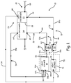
- FIG. 1 is a schematic diagram of system 10 that includes cooling circuits 12 and 14, which are arranged in parallel to reject heat produced by sources 16 and 18 to a cooling medium flowing through heat rejection line 20 via heat exchangers 22 and 24, respectively.
- Heat exchanger 22 is disposed upstream from heat exchanger 24 along line 20, which forms a series flow path through heat exchangers 22 and 24.
- heat exchangers 22 and 24 are heat exchanger cores of heat exchanger assembly 26, which are thermally insulated from each other by insulating layer 28 disposed between heat exchangers cores 22 and 24.
- system 10 is particularly suited for cooling heat sources 16 and 18 when heat source 18 imposes a heat load on circuit 14 that is greater than a heat load of source 16 imposed on circuit 12.
- Cooling circuit 12 includes heat source 16, heat exchanger 22, pump 30, supply line 32, and return line 34.
- Supply line 32 includes segments 32a and 32b.
- Supply line segment 32a fluidly connects outlet 36 of heat source 16 to suction side 38 (i.e., inlet side) of pump 30, and supply line segment 32b fluidly connects discharge side 40 (i.e., outlet side) of pump 30 to inlet 42 of heat exchanger 22.
- Return line 34 fluidly connects outlet 44 of heat exchanger 22 to inlet 46 of heat source 16.
- Pump 30 is positioned downstream from heat source 16 and upstream from heat exchanger 22 along supply line 32. Pump 30 acts on cooling medium 48 contained within cooling circuit 12 to drive medium 48 through circuit 12 in the direction indicated by the flow arrows in FIG. 1 .
- Cooling circuit 14 includes heat source 18, heat exchanger 24, pump 50, supply line 52, and return line 54.
- Supply line 52 includes segments 52a and 52b.
- Supply line segment 52a fluidly connects outlet 56 of heat source 18 to suction side 58 (i.e., inlet side) of pump 50, and supply line segment 52b fluidly connects discharge side 60 (i.e., outlet side) of pump 50 to inlet 62 of heat exchanger 24.
- Return line 54 fluidly connects outlet 64 of heat exchanger 24 to at least one inlet 66 of heat source 18.
- return line 54 includes main line 54a that forms branch lines 54b and 54c upstream from heat source 18.
- Branch line 54b fluidly connects supply line 54 to inlet 66b of heat source 18, and branch line 54c fluidly connects supply line 54 to inlet 66c of heat source 18.
- branch line 54c fluidly connects supply line 54 to inlet 66c of heat source 18.
- Configuring return line 54 with main line 54a, branch line 54b, and branch line 54c permits return line 54 to provide cooling medium 68 to two zones of heat source 18.
- Pump 50 acts on cooling medium 68 contained within cooling circuit 14 to drive medium 68 through circuit 14 in the direction indicated by the flow arrows in FIG. 1 .
- Cooling circuits 12 and 14 circulate cooling mediums 48 and 68, respectively, in order to reject heat produced by heat sources 16 and 18 to a cooling medium in heat rejection line 20 via heat exchangers 22 and 24.
- Heat exchangers 22 and 24 each communicate with rejection line 20, which has cooling medium 69 flowing in a direction indicated by the flow arrows in FIG. 1 .
- cooling medium 69 flows through heat exchanger 22 of cooling circuit 12 before flowing through heat exchanger 24 of cooling circuit 14.
- locating heat exchanger 22 upstream from heat exchanger 24 along line 20 permits cooling circuit 12 to remain cooler than cooling circuit 14.
- system 10 permits heat source 16 to be located adjacent to heat source 18 within zone 70 (shown schematically in FIG.
- pumps 30 and 50 can be coupled via shaft 72 such that both pumps can be driven by the same source.
- pumps are driven by a gearbox attached to the shaft extending from an engine (e.g., a gas turbine engine of an aircraft).
- system 10 is a parallel circuit cooling system when heat source 18 is a generator and heat source 16 is one or more electrical components (i.e., a generator controller) used to operate generator 18 on board an aircraft.
- generator 18 is driven by a gas turbine engine located on the aircraft. However, because the gas turbine engine has a variable speed, the rotational speed at which the turbine drives generator 18 changes. Moreover, generator 18 converts mechanical energy from the gas turbine engine into electrical power. The amount of electrical load on generator 18 varies as aircraft systems (i.e., environmental conditioning, radar, and other on-board electrical systems) are engaged and disengaged.
- Controller 16 monitors the speed of the gas turbine engine and electrical loads imposed on generator 18 and sends control signals to generator 18 such that generator 18 provides a consistent power output. Often the constant speed at the input to the generator is provided in an integrated drive generator unit.
- the term 'generator' used here includes the integrated drive generator.
- generator 18 contains high temperature rated electromagnetic components that permit generator 18 to operate within higher temperature environments than controller 16, which typically contains printed circuit boards and other less robust components.
- high temperature rated insulation wires used for generator windings permit generator 18 to operate at or below 200 °C whereas printed circuit boards and like components are typically designed to operate at or below 125 °C.
- the temperature of cooling medium 68 at inlets 66b and 66c is equal to or less than 100 °C and the temperature of cooling medium 68 at outlet 56 is equal to or less than 150 °C.
- generator 18 is designed to operate such that a temperature margin exists between a temperature of cooling medium 68 at outlet 56 and the maximum temperature allowed by generator 18.
- generator 18 includes a rotor and a stator as is known in the art. Because the rotor of generator 18 rotates relative to the stator, branch lines 54b and 54c deliver cooling medium 68 to the rotor and stator, respectively.
- Medium 48 flowing within cooling circuit 12 cools controller 16.
- the temperature of cooling medium 48 passing through outlet 36 is equal to or less than 100 °C, providing a similar operating margin between the maximum medium temperature at outlet 36 and the maximum allowable temperature of controller 16 (i.e., 125 °C).
- zone 70 is an unpressurized cavity within an aircraft that encloses generator 18 and controller 16. Placing controller 16 in close proximity to generator 18 exposes controller 16 to excess heat produced by generator 18. Additionally, if cooling medium 68 was used to cool controller 16 the temperature of cooling medium 68 passing through controller 16 would exceed the maximum operating temperature of controller 16. As such, the excess heat from generator 18 and the high temperature of cooling medium 68, if used in conjunction with controller 16 would cause controller 16 to exceed its maximum operating temperature. Therefore, system 10 permits generator 18 and controller 16 to be located adjacent to each other and in close proximity within zone 70 because cooling circuit 12 is a parallel to cooling circuit 14. Cooling circuit 12 cools generator 18 separately from controller 16 by using heat exchanger 26.
- Heat exchanger 26 includes heat exchanger cores 22 and 24 that are thermally-insulated from each other by insulators 28a-c. Additionally, because cooling circuit 12 communicates with heat exchanger 22, which is upstream from heat exchanger 24, the heat load from generator 18 is rejected into cooling medium 69 within line 20 downstream from heat exchanger 22. Thus, cooling medium 48 is maintained at an operating temperature that allows controller 16 to operate at a lower temperature than generator 18 whilst being exposed to the same environmental conditions within zone 70.
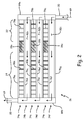
- FIG. 2 is a cross-sectional view of heat exchanger 26 taken along a longitudinal axis that is parallel to a flow direction of heat rejection line 20.
- Heat exchanger 26 is a multi-core heat exchanger having a plate-fin construction in which the first core is heat exchanger 22 and the second core is heat exchanger 24.
- Heat exchangers 22 and 24 have two or more alternating layers (e.g, six alternating layers 74a-f), that permit medium 48 of cooling circuit 12 and medium 68 of cooling circuit 14 to reject heat to medium 69 of heat rejection line 20.
- Layer 74a includes partition plates 76a and 76b, fins 78a and 80a, and insulator 28a.
- Partition plates 76a and 76b are generally parallel with respect to each other.
- Fins 78a of heat exchanger 22 are plates extending perpendicular to and between plates 76a and 76b to form a flow path for medium 48 of cooling circuit 12.
- fins 80a of heat exchanger 24 are plates extending perpendicular to and between partition plates 76a and 76b to form a separate flow path for medium 68 of cooling circuit 14.
- Fins 78a and 80a are generally parallel with respect to each other and with respect to fins 78b, 78c, 80b, and 80c.
- Insulator 28a is disposed between fins 78a and 80a, thus providing thermal insulation between heat exchanger 22 and heat exchanger 24.
- Layer 74b includes partition plates 76b and 76c as well as fins 82a (shown best in FIG. 3 ). Identically to layer 74a, partition plates 76b and 76c are generally parallel with respect to each other, and fins 82a are generally parallel with respect to each other and extend through layer 74b between partition plates 76b and 76c. However, unlike layer 74a, fins 82 extend in a generally perpendicular direction relative to fins 78a and 80a of layer 74a to form a flow path for medium 69 of heat rejection line 20.
- Layer 74c includes partition plates 76c and 76d, fins 78b and 80b, and insulator 28b.
- Layer 74e includes partition plates 76e and 76f, fins 78c and 80c, and insulator 28c.
- Layers 74c and 74e are constructed in an identical manner to layer 74a to form flow paths for mediums 48 and 68 of cooling circuits 12 and 14, respectively.
- Layer 74d includes partition plates 76d and 76e as well as fins 82b.
- Layer 74f includes partition plates 76f and 76g as well as fins 82c.
- Layers 74d and 74f are constructed in an identical manner to layer 74b to form flow paths for medium 69 of heat rejection line 20.
- End plates 84a and 84b are disposed along opposing ends of heat exchanger 26 to enclose layers 74a-f. Additionally, end plates 84a and 84b form inlet and outlet manifolds, respectively, for layers 74b, 74d, and 74f,
- Layer 74b is arranged between layers 74a and 74c.
- layer 74d is arranged between layers 74c and 74e, and layer 74f is arranged adjacent to layer 74e.
- layers 74b, 74d, and 74f which are configured to permit medium 69 of heat rejection line 20 to flow therein, are arranged such that layers 74a, 74c, and 74e are adjacent to respective layers to place cooling circuits 12 and 14 in a heat exchange relationship with heat rejection line 20.
- Insulators 28a, 28b, and 28c are arranged between adjacent fins within a layer to provide thermal insulation between heat exchanger cores 22 and 24. Specifically, positioning insulator 28a between fins 78a and 80a provides thermal insulation between heat exchanger cores 22 and 24 within layer 74a. Similarly, insulator 28b is arranged between fins 78b and 80b, and insulator 28c is arranged between fins 78c and 80c to provide thermal insulation between heat exchanger cores 22 and 24 within layers 74c and 74e, respectively. Together, insulators 28a, 28b, and 28c provide thermal resistance between cooling circuits 12 and 14, permitting cooling circuits 12 and 14 to operate at different temperatures without the hotter circuit unduly heating the cooler circuit. For example, cooling circuit 12 operates at a cooler temperature than cooling circuit 14 when heat source 16 produces less heat than heat source 18.
- FIG. 3 is a cross-sectional view of core 22 of heat exchanger 26 taken along a transverse axis that is generally perpendicular to a flow direction of heat rejection line 20.
- heat exchanger core 22 includes partition plates 74a and 74b arranged in a parallel relationship to permit fins 78a, extending between plates 74a and 74b to form a flow path for medium 48 of cooling circuit 12 through layer 74a.
- Layers 74b-74f are constructed as described in reference to FIG. 2 above.
- end plates 86a and 86b extend along opposing sides of heat exchanger 26 to enclose cores 22 and 24 (not shown in FIG. 3 ).
- End plates 86a and 86b also form inlet and outlet manifolds for layers 74a, 74c, and 74e, forming a multi-pass flow path through cores 22 and 24 (not shown in FIG. 3 ). Although, core 24 is not shown in FIG. 3 , an identical construction is used. Moreover, end plates 86a and 86b are configured to isolate cooling circuit 12 from cooling circuit 14.
- heat source 16 and 18 have been described as a controller and generator, heat sources 16 and 18 can also be a motor controller and motor, respectively.
- a motor generally produces more heat than the controller governing the rotational speed of the motor, and typically, the controller is not designed to withstand the maximum temperature of the motor.
- incorporating system 10 into a controller-motor arrangement permits the controller (i.e., heat source 16) to be located within the same higher temperature environment (i.e., zone 70) as the motor (i.e., heat source 18).
- system 10 is configured and operates as described with respect to the controller-generator arrangement.
- a system includes a heat exchanger, a first heat source, and a second heat source.
- the heat exchanger includes a first core, a second core, and a thermal barrier.
- the first core defines a first flow path through the heat exchanger along the first circuit
- the second core defines a second flow path through the heat exchanger along the second circuit that is parallel to the first flow path.
- the thermal barrier is disposed between the first and second cores such that the first and second flow paths are thermally insulated from each other.
- the system of the preceding paragraph can optionally include, additionally and/or alternatively, any one or more of the following features, configurations and/or additional components:
- a further embodiment of the foregoing system wherein a heat load generated by the second heat source is greater than a heat load generated by the first heat source.
- the second heat source is a generator and the first heat source includes electronic components disposed adjacent to the generator and configured to control an electrical output of the generator.
- first and second cores include multiple alternating layers of fins and plates
- the thermal barrier includes multiple thermal insulators in which each insulator is disposed between fins of the first core and fins of the second core that are adjacent to the fins of the first core.
- a further embodiment of any of the foregoing systems further includes a first pump and a second pump.
- the first pump is disposed between the electronic components and the heat exchanger along the first circuit.
- the second pump is disposed between the generator and the heat exchanger along the second circuit.
- the first and second pumps are driven by a gas turbine engine.
- a system includes a first circuit and a second circuit.
- the first circuit includes a first heat source, a first heat exchanger, a first supply line, a first return line, and a first pump.
- the first supply line extends from the first heat source to the first heat exchanger
- the first return line extends from the first heat exchanger to the first heat source.
- the first pump is configured to drive a first medium through the first circuit to place the first medium in a heat exchange relationship with the first heat source and the first heat exchanger.
- the second circuit includes a second heat source, a second heat exchanger, a second supply line, a second return line, and a second pump.
- the second supply line extends from the second heat source to the second heat exchanger, and the second return line extends from the second heat exchanger to the second heat source.
- the second pump is configured to drive a second medium through the second circuit to place the second medium in a heat exchange relationship with the second heat source and the second heat exchanger.
- the first and second heat exchangers are in a heat exchange relationship with a third medium along a heat exchanger line.
- the third medium communicates with the first heat exchanger upstream from the second heat exchanger.
- the system of the preceding paragraph can optionally include, additionally and/or alternatively, any one or more of the following features, configurations and/or additional components:
- a further embodiment of the foregoing system wherein the first heat source is a controller assembly, and the second heat source is a generator.
- the controller assembly facilitates operation of the generator.
- the second return line includes a first branch in a heat exchange relationship with a stator of the generator and a second branch in a heat exchange relationship with a rotor of the generator.
- the system further including a multi-core heat exchanger.
- the multi-core heat exchanger includes a first core formed by the first heat exchanger and a second core formed by the second heat exchanger.
- the first and second cores are integrally-attached, plate-fin heat exchangers.
- the multi-core heat exchanger further includes a thermally-insulating barrier disposed between the first and second cores of the multi-core heat exchanger.
- a method of cooling multiple heat sources includes passing a first medium through a first circuit to place the first medium in a heat exchange relationship with a first heat source and a first heat exchanger and passing a second medium through a second circuit to place the second medium in a heat exchange relationship with a second heat source and a second heat exchanger.
- the method further includes passing a third medium through the first and second heat exchangers, in series, to reject heat from the first and second heat sources.
- the heat load of the second heat source is greater than a heat load of a first heat source.
- the method of the preceding paragraph can optionally include, additionally and/or alternatively, any one or more of the following features, configurations and/or additional components:
- passing the first medium through the first circuit includes using a first pump disposed between the first heat source and the first heat exchanger along a first supply line to circulate the first medium through the first circuit
- passing the second medium through the second circuit includes using a second pump disposed between the second heat source and the second heat exchanger along a second supply line to circulate the second medium through the second circuit.
- the second heat source is a generator controlled by the electronics module, the electronics module being disposed adjacent to the generator.
- the method further including passing the second medium through a first branch of a second return line to place the second medium in a heat exchange relationship with a stator of the generator.
- the method further including passing the third medium through a multi-core heat exchanger.
- the multi-core heat exchanger includes a first core, a second core, and an insulating member.
- the first core is formed by the first heat exchanger and the second core is formed by the second heat exchanger, the second core is integrally-attached to the first core.
- the insulating member is disposed between the first and second cores.
- the method further includes driving the first and second pumps with a gas turbine engine.
Landscapes
- Engineering & Computer Science (AREA)
- Microelectronics & Electronic Packaging (AREA)
- Physics & Mathematics (AREA)
- Thermal Sciences (AREA)
- Power Engineering (AREA)
- Mechanical Engineering (AREA)
- General Engineering & Computer Science (AREA)
- Aviation & Aerospace Engineering (AREA)
- Motor Or Generator Cooling System (AREA)
- Details Of Heat-Exchange And Heat-Transfer (AREA)
Abstract
Description
- The present invention relates generally to systems for cooling multiple heat loads and, more particularly, to systems for cooling generators and associated electronics driven by gas turbine engines installed on aircraft.
- Aircraft use a gas turbine engine to drive a generator, producing on-board electrical power. The electric power is used to operate instruments, environmental control systems, radar, and various other aircraft systems. The rotational speed of the gas turbine engine varies during the operation of the aircraft, increasing or decreasing speed to vary aircraft speed. Consequently, the input speed driving the generator varies along with the speed of the gas turbine engine. Additionally, the electrical load on the generator varies as various aircraft systems are engaged and disengaged. To maintain a substantially constant speed of the generator, a generator control module monitors the speed of the generator input shaft and the electrical load imposed on the generator. Because generator control modules typically include electronic components that have lower allowable maximum temperature limits compared to generator, some systems place the generator control module in a pressurized and temperature-controlled electronics bay within the aircraft. While placing the generator control unit within the electronics bay provides an acceptable environment for the electronics, the distance between the generator control unit and the generator increases the complexity of the generator system. Moreover, some aircraft require compact system configurations that do not allow electronics to be placed in separate bays.
- Therefore, a need exists to develop a cooling system that enables electronics for operating the generator to be located outside of a temperature-controlled and pressurized bay.
- In some embodiments, a system includes a heat exchanger, a first heat source disposed along a first circuit, and a second heat source disposed along a second circuit. The heat exchanger includes a first core defining a first flow path through the heat exchanger and along the first circuit and a second core defining a second flow path through the heat exchanger and along the second circuit that is parallel to the first flow path. The first and second cores define a third flow path extending through the heat exchanger that is configured to be in a heat exchange relationship with the first and second flow paths.
- In another embodiment, a method includes passing a first medium through a first circuit in a heat exchange relationship with a first heat exchanger, and passing a second medium through a second circuit in heat exchange relationship with a second heat exchanger. The method further includes passing a third medium through the first and second heat exchangers in series to reject heat from the first and second heat sources. A heat load from the second heat source is greater than a heat load from the first heat source.
- In another embodiment, which the Applicant expressly reserves the right to claim independently, a system includes a first cooling circuit and a second cooling circuit. The first cooling circuit includes a first heat source, a first heat exchanger, a first supply line, a first return line, and a first pump. The first supply line extends from the first heat source to the first heat exchanger, and the first return line extends from the first heat exchanger to the first heat source. The first pump is disposed between the first heat exchanger and the first heat source along the first supply line, the first pump configured to drive a first medium through the first circuit to place the first medium in a heat exchange relationship with the first heat source and the first heat exchanger. The second cooling circuit includes a second heat source, a second heat exchanger, a second supply line, a second return line, and a second pump. The second supply line extends from the second heat source to the second heat exchanger, and the second return line extends from the second heat exchanger to the second heat source. The second pump is disposed between the second heat exchanger and the second heat source along the second supply line, the second pump configured to drive a second medium through the second circuit to place the second medium in a heat exchange relationship with the second heat source and the second heat exchanger. The first and second heat exchangers are in a heat exchange relationship with a third medium along a heat exchanger line such that the third medium communicates with the first heat exchanger upstream from the second heat exchanger. In this system, the first heat source may be a controller assembly and the second heat source may be a generator, wherein the controller assembly facilitates operation of the generator. The second return line may comprise a first branch in a heat exchange relationship with a stator of the generator, and a second branch in a heat exchange relationship with a rotor of the generator. The first and second pumps may be driven by a gas turbine engine. The system may further comprise a multi-core heat exchanger comprising a first core formed by the first heat exchanger, and a second core formed by the second heat exchanger, wherein the first and second cores are integrally-attached, plate-fin heat exchangers. The multi-core heat exchanger may further comprise a thermally-insulating barrier disposed between the first and second cores of the multi-core heat exchanger.
-
-
FIG. 1 is a schematic diagram of a multi-circuit system for cooling a first heat source and a second heat source adjacent to the first heat source. -
FIG. 2 is a cross-sectional view taken along a longitudinal direction of a multi-core heat exchanger having thermally-isolated cores. -
FIG. 3 is a cross-sectional view taken perpendicular to the longitudinal direction of the multi-core heat exchanger ofFIG. 2 . -
FIG. 1 is a schematic diagram ofsystem 10 that includescooling circuits sources heat rejection line 20 viaheat exchangers Heat exchanger 22 is disposed upstream fromheat exchanger 24 alongline 20, which forms a series flow path throughheat exchangers heat exchangers heat exchanger assembly 26, which are thermally insulated from each other by insulatinglayer 28 disposed betweenheat exchangers cores system 10 is particularly suited forcooling heat sources heat source 18 imposes a heat load oncircuit 14 that is greater than a heat load ofsource 16 imposed oncircuit 12. -
Cooling circuit 12 includesheat source 16,heat exchanger 22,pump 30,supply line 32, andreturn line 34.Supply line 32 includessegments Supply line segment 32a fluidly connectsoutlet 36 ofheat source 16 to suction side 38 (i.e., inlet side) ofpump 30, andsupply line segment 32b fluidly connects discharge side 40 (i.e., outlet side) ofpump 30 toinlet 42 ofheat exchanger 22.Return line 34 fluidly connectsoutlet 44 ofheat exchanger 22 toinlet 46 ofheat source 16.Pump 30 is positioned downstream fromheat source 16 and upstream fromheat exchanger 22 alongsupply line 32.Pump 30 acts oncooling medium 48 contained withincooling circuit 12 to drivemedium 48 throughcircuit 12 in the direction indicated by the flow arrows inFIG. 1 . -
Cooling circuit 14 includesheat source 18,heat exchanger 24,pump 50,supply line 52, andreturn line 54.Supply line 52 includessegments Supply line segment 52a fluidly connectsoutlet 56 ofheat source 18 to suction side 58 (i.e., inlet side) ofpump 50, andsupply line segment 52b fluidly connects discharge side 60 (i.e., outlet side) ofpump 50 toinlet 62 ofheat exchanger 24.Return line 54 fluidly connectsoutlet 64 ofheat exchanger 24 to at least oneinlet 66 ofheat source 18. In some embodiments,return line 54 includesmain line 54a that formsbranch lines heat source 18.Branch line 54b fluidly connectssupply line 54 toinlet 66b ofheat source 18, andbranch line 54c fluidly connectssupply line 54 toinlet 66c ofheat source 18. As will be explained in greater detail below, configuringreturn line 54 withmain line 54a,branch line 54b, andbranch line 54cpermits return line 54 to providecooling medium 68 to two zones ofheat source 18.Pump 50 acts oncooling medium 68 contained withincooling circuit 14 to drivemedium 68 throughcircuit 14 in the direction indicated by the flow arrows inFIG. 1 . -
Cooling circuits cooling mediums heat sources heat rejection line 20 viaheat exchangers Heat exchangers rejection line 20, which has coolingmedium 69 flowing in a direction indicated by the flow arrows inFIG. 1 . In some embodiments,cooling medium 69 flows throughheat exchanger 22 ofcooling circuit 12 before flowing throughheat exchanger 24 ofcooling circuit 14. Whenheat source 18 produces more heat thanheat source 16, locatingheat exchanger 22 upstream fromheat exchanger 24 alongline 20 permitscooling circuit 12 to remain cooler thancooling circuit 14. Thus, becausecooling circuit 12 remains cooler thancooling circuit 14,system 10 permitsheat source 16 to be located adjacent toheat source 18 within zone 70 (shown schematically inFIG. 1 ). Moreover,pumps shaft 72 such that both pumps can be driven by the same source. In some embodiments, pumps are driven by a gearbox attached to the shaft extending from an engine (e.g., a gas turbine engine of an aircraft). - In some embodiments,
system 10 is a parallel circuit cooling system whenheat source 18 is a generator andheat source 16 is one or more electrical components (i.e., a generator controller) used to operategenerator 18 on board an aircraft. In such embodiments,generator 18 is driven by a gas turbine engine located on the aircraft. However, because the gas turbine engine has a variable speed, the rotational speed at which the turbine drivesgenerator 18 changes. Moreover,generator 18 converts mechanical energy from the gas turbine engine into electrical power. The amount of electrical load ongenerator 18 varies as aircraft systems (i.e., environmental conditioning, radar, and other on-board electrical systems) are engaged and disengaged.Controller 16 monitors the speed of the gas turbine engine and electrical loads imposed ongenerator 18 and sends control signals togenerator 18 such thatgenerator 18 provides a consistent power output. Often the constant speed at the input to the generator is provided in an integrated drive generator unit. The term 'generator' used here includes the integrated drive generator. - Generally,
generator 18 contains high temperature rated electromagnetic components that permitgenerator 18 to operate within higher temperature environments thancontroller 16, which typically contains printed circuit boards and other less robust components. For example, high temperature rated insulation wires used for generator windings permitgenerator 18 to operate at or below 200 °C whereas printed circuit boards and like components are typically designed to operate at or below 125 °C. In some embodiments, the temperature of cooling medium 68 atinlets outlet 56 is equal to or less than 150 °C. Thus,generator 18 is designed to operate such that a temperature margin exists between a temperature of cooling medium 68 atoutlet 56 and the maximum temperature allowed bygenerator 18. This operatingmargin permits generator 18 to operate at higher temperatures between the maximum normal operating temperature (i.e., 150 °C) and the maximum operating temperature (i.e., 200 °C) for short transient periods. Moreover,generator 18 includes a rotor and a stator as is known in the art. Because the rotor ofgenerator 18 rotates relative to the stator,branch lines - The less robust components (i.e., printed circuit boards and like components) of
controller 16, typically, are not designed to withstand the operationalenvironment enclosing generator 18.Medium 48 flowing within coolingcircuit 12 coolscontroller 16. In some embodiments, the temperature of cooling medium 48 passing throughoutlet 36 is equal to or less than 100 °C, providing a similar operating margin between the maximum medium temperature atoutlet 36 and the maximum allowable temperature of controller 16 (i.e., 125 °C). - Moreover, in such embodiments,
zone 70 is an unpressurized cavity within an aircraft that enclosesgenerator 18 andcontroller 16. Placingcontroller 16 in close proximity togenerator 18 exposescontroller 16 to excess heat produced bygenerator 18. Additionally, if coolingmedium 68 was used tocool controller 16 the temperature of cooling medium 68 passing throughcontroller 16 would exceed the maximum operating temperature ofcontroller 16. As such, the excess heat fromgenerator 18 and the high temperature of coolingmedium 68, if used in conjunction withcontroller 16 would causecontroller 16 to exceed its maximum operating temperature. Therefore,system 10permits generator 18 andcontroller 16 to be located adjacent to each other and in close proximity withinzone 70 because coolingcircuit 12 is a parallel to coolingcircuit 14. Coolingcircuit 12 coolsgenerator 18 separately fromcontroller 16 by usingheat exchanger 26.Heat exchanger 26 includesheat exchanger cores insulators 28a-c. Additionally, because coolingcircuit 12 communicates withheat exchanger 22, which is upstream fromheat exchanger 24, the heat load fromgenerator 18 is rejected into coolingmedium 69 withinline 20 downstream fromheat exchanger 22. Thus, coolingmedium 48 is maintained at an operating temperature that allowscontroller 16 to operate at a lower temperature thangenerator 18 whilst being exposed to the same environmental conditions withinzone 70. -
FIG. 2 is a cross-sectional view ofheat exchanger 26 taken along a longitudinal axis that is parallel to a flow direction ofheat rejection line 20.Heat exchanger 26 is a multi-core heat exchanger having a plate-fin construction in which the first core isheat exchanger 22 and the second core isheat exchanger 24.Heat exchangers layers 74a-f), that permitmedium 48 of coolingcircuit 12 andmedium 68 of coolingcircuit 14 to reject heat tomedium 69 ofheat rejection line 20. -
Layer 74a includespartition plates fins insulator 28a.Partition plates Fins 78a ofheat exchanger 22 are plates extending perpendicular to and betweenplates medium 48 of coolingcircuit 12. Likewise,fins 80a ofheat exchanger 24 are plates extending perpendicular to and betweenpartition plates medium 68 of coolingcircuit 14.Fins fins Insulator 28a is disposed betweenfins heat exchanger 22 andheat exchanger 24. -
Layer 74b includespartition plates fins 82a (shown best inFIG. 3 ). Identically tolayer 74a,partition plates fins 82a are generally parallel with respect to each other and extend throughlayer 74b betweenpartition plates layer 74a, fins 82 extend in a generally perpendicular direction relative tofins layer 74a to form a flow path formedium 69 ofheat rejection line 20. -
Layer 74c includespartition plates fins insulator 28b.Layer 74e includespartition plates fins insulator 28c.Layers mediums cooling circuits -
Layer 74d includespartition plates fins 82b.Layer 74f includespartition plates fins 82c.Layers medium 69 ofheat rejection line 20. -
End plates heat exchanger 26 to encloselayers 74a-f. Additionally,end plates layers -
Layer 74b is arranged betweenlayers layer 74d is arranged betweenlayers layer 74f is arranged adjacent tolayer 74e. Thus, layers 74b, 74d, and 74f, which are configured to permitmedium 69 ofheat rejection line 20 to flow therein, are arranged such thatlayers circuits heat rejection line 20. -
Insulators heat exchanger cores positioning insulator 28a betweenfins heat exchanger cores layer 74a. Similarly,insulator 28b is arranged betweenfins insulator 28c is arranged betweenfins heat exchanger cores layers insulators cooling circuits circuits circuit 12 operates at a cooler temperature than coolingcircuit 14 whenheat source 16 produces less heat thanheat source 18. -
FIG. 3 is a cross-sectional view ofcore 22 ofheat exchanger 26 taken along a transverse axis that is generally perpendicular to a flow direction ofheat rejection line 20. As described above,heat exchanger core 22 includespartition plates fins 78a, extending betweenplates medium 48 of coolingcircuit 12 throughlayer 74a.Layers 74b-74f are constructed as described in reference toFIG. 2 above. Additionally,end plates heat exchanger 26 to enclosecores 22 and 24 (not shown inFIG. 3 ).End plates layers cores 22 and 24 (not shown inFIG. 3 ). Although,core 24 is not shown inFIG. 3 , an identical construction is used. Moreover,end plates circuit 12 from coolingcircuit 14. - Although
heat source heat sources system 10 into a controller-motor arrangement permits the controller (i.e., heat source 16) to be located within the same higher temperature environment (i.e., zone 70) as the motor (i.e., heat source 18). In a controller-motor arrangement,system 10 is configured and operates as described with respect to the controller-generator arrangement. - The following are non-exclusive descriptions of possible embodiments of the present invention.
- A system includes a heat exchanger, a first heat source, and a second heat source. The heat exchanger includes a first core, a second core, and a thermal barrier. The first core defines a first flow path through the heat exchanger along the first circuit, and the second core defines a second flow path through the heat exchanger along the second circuit that is parallel to the first flow path. The thermal barrier is disposed between the first and second cores such that the first and second flow paths are thermally insulated from each other.
- The system of the preceding paragraph can optionally include, additionally and/or alternatively, any one or more of the following features, configurations and/or additional components:
- A further embodiment of the foregoing system, wherein a heat load generated by the second heat source is greater than a heat load generated by the first heat source.
- A further embodiment of any of the foregoing systems, wherein the second heat source is a generator and the first heat source includes electronic components disposed adjacent to the generator and configured to control an electrical output of the generator.
- A further embodiment of any of the foregoing systems, wherein the third flow path defines a portion of a fuel system.
- A further embodiment of any of the foregoing systems, wherein the first and second cores include multiple alternating layers of fins and plates, and wherein the thermal barrier includes multiple thermal insulators in which each insulator is disposed between fins of the first core and fins of the second core that are adjacent to the fins of the first core.
- A further embodiment of any of the foregoing systems further includes a first pump and a second pump. The first pump is disposed between the electronic components and the heat exchanger along the first circuit. The second pump is disposed between the generator and the heat exchanger along the second circuit. The first and second pumps are driven by a gas turbine engine.
- A system includes a first circuit and a second circuit. The first circuit includes a first heat source, a first heat exchanger, a first supply line, a first return line, and a first pump. The first supply line extends from the first heat source to the first heat exchanger, and the first return line extends from the first heat exchanger to the first heat source. The first pump is configured to drive a first medium through the first circuit to place the first medium in a heat exchange relationship with the first heat source and the first heat exchanger. The second circuit includes a second heat source, a second heat exchanger, a second supply line, a second return line, and a second pump. The second supply line extends from the second heat source to the second heat exchanger, and the second return line extends from the second heat exchanger to the second heat source. The second pump is configured to drive a second medium through the second circuit to place the second medium in a heat exchange relationship with the second heat source and the second heat exchanger. The first and second heat exchangers are in a heat exchange relationship with a third medium along a heat exchanger line. The third medium communicates with the first heat exchanger upstream from the second heat exchanger.
- The system of the preceding paragraph can optionally include, additionally and/or alternatively, any one or more of the following features, configurations and/or additional components:
- A further embodiment of the foregoing system, wherein the first heat source is a controller assembly, and the second heat source is a generator. The controller assembly facilitates operation of the generator.
- A further embodiment of any of the foregoing systems, wherein the second return line includes a first branch in a heat exchange relationship with a stator of the generator and a second branch in a heat exchange relationship with a rotor of the generator.
- A further embodiment of any of the foregoing systems, wherein the first and second pumps are driven by a gas turbine engine.
- A further embodiment of any of the foregoing systems, the system further including a multi-core heat exchanger. The multi-core heat exchanger includes a first core formed by the first heat exchanger and a second core formed by the second heat exchanger. The first and second cores are integrally-attached, plate-fin heat exchangers.
- A further embodiment of any of the foregoing systems, the multi-core heat exchanger further includes a thermally-insulating barrier disposed between the first and second cores of the multi-core heat exchanger.
- A method of cooling multiple heat sources includes passing a first medium through a first circuit to place the first medium in a heat exchange relationship with a first heat source and a first heat exchanger and passing a second medium through a second circuit to place the second medium in a heat exchange relationship with a second heat source and a second heat exchanger. The method further includes passing a third medium through the first and second heat exchangers, in series, to reject heat from the first and second heat sources. The heat load of the second heat source is greater than a heat load of a first heat source.
- The method of the preceding paragraph can optionally include, additionally and/or alternatively, any one or more of the following features, configurations and/or additional components:
- A further embodiment of the foregoing method, wherein passing the first medium through the first circuit includes using a first pump disposed between the first heat source and the first heat exchanger along a first supply line to circulate the first medium through the first circuit
- A further embodiment of any of the foregoing methods, wherein passing the second medium through the second circuit includes using a second pump disposed between the second heat source and the second heat exchanger along a second supply line to circulate the second medium through the second circuit.
- A further embodiment of any of the foregoing methods, wherein the first heat source is an electronics module.
- A further embodiment of any of the foregoing methods, wherein the second heat source is a generator controlled by the electronics module, the electronics module being disposed adjacent to the generator.
- A further embodiment of any of the foregoing methods, the method further including passing the second medium through a first branch of a second return line to place the second medium in a heat exchange relationship with a stator of the generator.
- A further embodiment of any of the foregoing methods, the method further including passing the third medium through a multi-core heat exchanger. The multi-core heat exchanger includes a first core, a second core, and an insulating member. The first core is formed by the first heat exchanger and the second core is formed by the second heat exchanger, the second core is integrally-attached to the first core. The insulating member is disposed between the first and second cores.
- A further embodiment of any of the foregoing methods, the method further includes driving the first and second pumps with a gas turbine engine.
- A further embodiment of any of the foregoing methods, wherein the first and second mediums are liquid heat exchange fluids, and the third medium is fuel.
- While the invention has been described with reference to an exemplary embodiment(s), it will be understood by those skilled in the art that various changes may be made and equivalents may be substituted for elements thereof without departing from the scope of the invention. In addition, many modifications may be made to adapt a particular situation or material to the teachings of the invention without departing from the essential scope thereof. Therefore, it is intended that the invention not be limited to the particular embodiment(s) disclosed, but that the invention will include all embodiments falling within the scope of the appended claims.
Claims (14)
- A system (10) comprising:a heat exchanger (26) comprising:a first core (22) defining a first flow path through the heat exchanger (26);a second core (24) defining a second flow path through the heat exchanger (26) that is parallel to the first flow path, wherein the first and second cores (22, 24) define a third flow path extending through the heat exchanger (26) that is configured to be in a heat exchange relationship with the first and second flow paths; anda thermal barrier (28) disposed between the first and second cores (22, 24) such that the first and second flow paths are thermally insulated from each other;a first heat source (16) disposed along a first circuit (12) that includes the first flow path of the heat exchanger (26); anda second heat source (18) disposed along a second circuit (14) that includes the second flow path of the heat exchanger (26).
- The system (10) of claim 1, wherein a heat load generated by the second heat source (18) is greater than a heat load generated by the first heat source (16).
- The system (10) of claim 1 or 2, wherein the second heat source (18) is a generator and the first heat source (16) includes electronic components disposed adjacent to the generator (18) and configured to control an electrical output of the generator (18).
- The system (10) of claim 3, further comprising:a first pump (30) disposed between the electronic components and the heat exchanger (22) along the first circuit (12); anda second pump (50) disposed between the generator and the heat exchanger (24) along the second circuit (14), wherein the first and second pumps (30, 50) are driven by a gas turbine engine.
- The system (10) of any preceding claim, wherein the third flow path defines a portion of a fuel system.
- The system (10) of any preceding claim, wherein:the first and second cores (22, 24) include multiple alternating layers (74a-f) of fins (78a-c, 80a-c) and plates (76a-f), andthe thermal barrier (28) includes multiple thermal insulators (28a-c) in which each insulator (28a-c) is disposed between fins (78a-c) of the first core (22) and fins (80a-c) of the second core (24) that are adjacent to the fins (78a-c) of the first core (22).
- The system (10) of claim 6, wherein the first and second cores (22, 24) are integrated into a single heat exchanger body (26).
- A method comprising:passing a first medium (48) through a first circuit (12), wherein the first medium (48) is in a heat exchange relationship with a first heat source (16) and a first heat exchanger (22);passing a second medium (68) through a second circuit (14), wherein the second medium (68) is in a heat exchanger relationship with a second heat source (18) and a second heat exchanger (24);passing a third medium (69) through the first and second heat exchangers (22, 24), in series, to reject heat from the first and second heat sources (16, 18), wherein a heat load of the second heat source (18) is greater than a heat load of the first heat source (16).
- The method of claim 8, wherein:passing the first medium (48) through the first circuit (12) includes using a first pump (30) disposed between the first heat source (16) and the first heat exchanger (22) along a first supply line (32) to circulate the first medium (48) through the first circuit (12); andpassing the second medium (68) through the second circuit (14) includes using a second pump (50) disposed between the second heat source (18) and the second heat exchanger (24) along a second supply line (52) to circulate the second medium (68) through the second circuit (14).
- The method of claim 9, wherein:the first heat source (16) is an electronics module; andthe second heat source (18) is a generator controlled by the electronics module, wherein the electronics module is disposed adjacent to the generator.
- The method of claim 10 and further comprising:passing the second medium (68) through a first branch (54c) of a second return line (54) to place the second medium (68) in a heat exchange relationship with a stator of the generator, wherein the second return line (54) extends from the second heat exchanger (24) to the generator; andpassing the second medium (68) through a second branch (54b) of the second return line (54) to place the second medium (68) in a heat exchange relationship with a rotor of the generator.
- The method of claim 10 or 11 and further comprising:driving the first and second pumps (30, 50) with the generator (18).
- The method of any of claims 9 to 12 and further comprising:passing the third medium (69) through a multi-core heat exchanger (26) comprising:a first core (22) formed by the first heat exchanger (22);a second core (24) formed by the second heat exchanger (24), the second core (24) being integrally-attached to the first core (22); andan insulating member (28) disposed between the first and second cores (22,24).
- The method of any of claims 9 to 13, wherein:the first and second mediums (48, 68) are liquid heat exchange fluids; andthe third medium is fuel (69).
Applications Claiming Priority (1)
| Application Number | Priority Date | Filing Date | Title |
|---|---|---|---|
| US14/859,866 US20170081040A1 (en) | 2015-09-21 | 2015-09-21 | Heat exchanger and cooling system for generator electronics cooling |
Publications (3)
| Publication Number | Publication Date |
|---|---|
| EP3144623A2 true EP3144623A2 (en) | 2017-03-22 |
| EP3144623A3 EP3144623A3 (en) | 2017-06-21 |
| EP3144623B1 EP3144623B1 (en) | 2018-12-12 |
Family
ID=57144735
Family Applications (1)
| Application Number | Title | Priority Date | Filing Date |
|---|---|---|---|
| EP16188843.3A Active EP3144623B1 (en) | 2015-09-21 | 2016-09-14 | Heat exchanger and cooling system for generator electronics cooling |
Country Status (2)
| Country | Link |
|---|---|
| US (1) | US20170081040A1 (en) |
| EP (1) | EP3144623B1 (en) |
Cited By (2)
| Publication number | Priority date | Publication date | Assignee | Title |
|---|---|---|---|---|
| WO2019017792A1 (en) * | 2017-07-20 | 2019-01-24 | E-Traction Europe B.V. | Motor drive unit with liquid cooling |
| EP4266555A1 (en) * | 2022-04-21 | 2023-10-25 | Hamilton Sundstrand Corporation | Power generator cooling system |
Families Citing this family (11)
| Publication number | Priority date | Publication date | Assignee | Title |
|---|---|---|---|---|
| US10636725B2 (en) * | 2017-12-19 | 2020-04-28 | Veoneer Us Inc. | Electrical module cooling through waste heat recovery |
| US11018556B2 (en) | 2019-03-15 | 2021-05-25 | Hamilton Sunstrand Corporation | Generators operable with shared oil systems and independent oil systems |
| US11261792B2 (en) | 2019-11-15 | 2022-03-01 | General Electric Company | Thermal management system with thermal bus for a gas turbine engine or aircraft |
| US11820526B2 (en) * | 2020-02-26 | 2023-11-21 | Honda Motor Co., Ltd. | Power supply apparatus for a flying body including a combustion gas and intake air heat exchanger |
| US11591965B2 (en) | 2021-03-29 | 2023-02-28 | General Electric Company | Thermal management system for transferring heat between fluids |
| US12024308B2 (en) | 2021-12-16 | 2024-07-02 | Rolls-Royce Corporation | Propeller driven backup cooling pump system for electric motor converter |
| US12296972B2 (en) | 2021-12-22 | 2025-05-13 | Honda Motor Co., Ltd. | Airflow guide structure and aircraft |
| JP7571002B2 (en) | 2021-12-22 | 2024-10-22 | 本田技研工業株式会社 | aircraft |
| JP7692347B2 (en) | 2021-12-28 | 2025-06-13 | 本田技研工業株式会社 | Aircraft and method |
| CN115942598B (en) | 2023-01-09 | 2023-05-16 | 西安交通大学 | Modularized square-round composite channel printed circuit board heat exchanger |
| US12331680B2 (en) | 2023-02-03 | 2025-06-17 | Rtx Corporation | Turbine engine bottoming cycle heat exchanger bypass |
Family Cites Families (15)
| Publication number | Priority date | Publication date | Assignee | Title |
|---|---|---|---|---|
| US3513907A (en) * | 1968-04-17 | 1970-05-26 | United Aircraft Prod | Plural mode heat exchange apparatus |
| GB2095756B (en) * | 1982-03-05 | 1985-01-16 | United Technologies Corp | Balancing the heat flow between components associated with a gas turbine engine |
| US5105875A (en) * | 1991-01-10 | 1992-04-21 | Sundstrand Corporation | Cooling system for auxiliary power unit |
| US5271248A (en) * | 1991-08-23 | 1993-12-21 | Sundstrand Corporation | Dual cooling system |
| ES2127472T3 (en) * | 1994-04-12 | 1999-04-16 | Showa Aluminum Corp | STACKED DUPLEX HEAT EXCHANGER. |
| GB9817879D0 (en) * | 1998-08-18 | 1998-10-14 | British Aerospace | Combined environmental control and power system for aircraft |
| DE19960960C1 (en) * | 1999-12-17 | 2001-04-26 | Bosch Gmbh Robert | Heat exchanger system for hybrid vehicle passenger compartment heating utilizes waste heat generated by power semiconductors that control electric drive motor of hybrid drive |
| DE10134678A1 (en) * | 2001-07-20 | 2003-02-06 | Bosch Gmbh Robert | Arrangement for cooling and heating motor vehicle, has at least one bypass line with bypass valve associated with and arranged in parallel with at least one auxiliary radiator segment |
| WO2005036721A2 (en) * | 2003-10-06 | 2005-04-21 | Edward Woods | Power generation systems and methods of generating power |
| JP4621487B2 (en) * | 2003-12-02 | 2011-01-26 | 昭和電工株式会社 | Integrated heat exchanger |
| DE10360226A1 (en) * | 2003-12-20 | 2005-07-21 | Mtu Aero Engines Gmbh | Gas turbine, in particular aircraft engine |
| US7260926B2 (en) * | 2004-01-20 | 2007-08-28 | United Technologies Corporation | Thermal management system for an aircraft |
| US8079407B2 (en) * | 2006-11-09 | 2011-12-20 | Honeywell International Inc. | Integrated heat exchangers for ECS and OBIGGS applications |
| EP2239435A1 (en) * | 2009-04-06 | 2010-10-13 | Alstom Technology Ltd | Electrical generator and method for operating a cooling circuit of an electrical generator |
| US8657227B1 (en) * | 2009-09-11 | 2014-02-25 | The Boeing Company | Independent power generation in aircraft |
-
2015
- 2015-09-21 US US14/859,866 patent/US20170081040A1/en not_active Abandoned
-
2016
- 2016-09-14 EP EP16188843.3A patent/EP3144623B1/en active Active
Non-Patent Citations (1)
| Title |
|---|
| None |
Cited By (6)
| Publication number | Priority date | Publication date | Assignee | Title |
|---|---|---|---|---|
| WO2019017792A1 (en) * | 2017-07-20 | 2019-01-24 | E-Traction Europe B.V. | Motor drive unit with liquid cooling |
| NL2019308B1 (en) * | 2017-07-20 | 2019-02-12 | E Traction Europe Bv | Motor drive unit with liquid cooling |
| US11225133B2 (en) | 2017-07-20 | 2022-01-18 | E-Traction Europe B.V. | Motor drive unit with liquid cooling |
| RU2765688C2 (en) * | 2017-07-20 | 2022-02-02 | И-Трэкшн Юроп Б.В. | Motor drive unit with liquid cooling |
| EP4266555A1 (en) * | 2022-04-21 | 2023-10-25 | Hamilton Sundstrand Corporation | Power generator cooling system |
| US12166405B2 (en) | 2022-04-21 | 2024-12-10 | Hamilton Sundstrand Corporation | Power generator cooling system |
Also Published As
| Publication number | Publication date |
|---|---|
| EP3144623B1 (en) | 2018-12-12 |
| EP3144623A3 (en) | 2017-06-21 |
| US20170081040A1 (en) | 2017-03-23 |
Similar Documents
| Publication | Publication Date | Title |
|---|---|---|
| EP3144623B1 (en) | Heat exchanger and cooling system for generator electronics cooling | |
| CN116981621B (en) | Aircraft propulsion unit | |
| US11794913B2 (en) | Integrated electric propulsion unit | |
| CN109562836B (en) | Electric propulsion system | |
| CN109072710B (en) | Drive system with generator for aircraft | |
| EP3043046B1 (en) | Controller cooling arrangement | |
| US11261755B2 (en) | Hydraulic system | |
| US7434765B2 (en) | Heat exchanger systems and associated systems and methods for cooling aircraft starter/generators | |
| EP3628598B1 (en) | Power converter cooling | |
| US20150082804A1 (en) | Turbine engine incorporating thermoelectric generators | |
| US11996760B2 (en) | Aircraft electric motor having a stator heat pipe cooling scheme | |
| EP4175130B1 (en) | Aircraft electric motor with integrated cooling system | |
| US20250196584A1 (en) | High voltage pump and heater assembly with scavenge path | |
| US11165309B2 (en) | Motor cooling system and method | |
| US11984789B2 (en) | Cooling device and speed change drive unit | |
| EP3907393A1 (en) | Thermal management system and method of use | |
| US20170082325A1 (en) | Thermoelectric cooling system | |
| EP2716889B1 (en) | Redundant cooling for fluid cooled systems | |
| US12166405B2 (en) | Power generator cooling system | |
| US11990825B2 (en) | Aircraft electric motor | |
| US20260101469A1 (en) | Dual redundant cold plate | |
| EP4574429A1 (en) | An electric propulsion unit | |
| EP4002396A1 (en) | Thermal management for a motor feeder |
Legal Events
| Date | Code | Title | Description |
|---|---|---|---|
| PUAI | Public reference made under article 153(3) epc to a published international application that has entered the european phase |
Free format text: ORIGINAL CODE: 0009012 |
|
| STAA | Information on the status of an ep patent application or granted ep patent |
Free format text: STATUS: THE APPLICATION HAS BEEN PUBLISHED |
|
| AK | Designated contracting states |
Kind code of ref document: A2 Designated state(s): AL AT BE BG CH CY CZ DE DK EE ES FI FR GB GR HR HU IE IS IT LI LT LU LV MC MK MT NL NO PL PT RO RS SE SI SK SM TR |
|
| AX | Request for extension of the european patent |
Extension state: BA ME |
|
| PUAL | Search report despatched |
Free format text: ORIGINAL CODE: 0009013 |
|
| AK | Designated contracting states |
Kind code of ref document: A3 Designated state(s): AL AT BE BG CH CY CZ DE DK EE ES FI FR GB GR HR HU IE IS IT LI LT LU LV MC MK MT NL NO PL PT RO RS SE SI SK SM TR |
|
| AX | Request for extension of the european patent |
Extension state: BA ME |
|
| RIC1 | Information provided on ipc code assigned before grant |
Ipc: H02K 9/00 20060101ALI20170515BHEP Ipc: H02K 7/18 20060101ALI20170515BHEP Ipc: F28D 9/00 20060101AFI20170515BHEP Ipc: H02K 19/36 20060101ALI20170515BHEP Ipc: H02K 11/30 20160101ALI20170515BHEP Ipc: H05K 7/20 20060101ALI20170515BHEP Ipc: H02K 9/19 20060101ALI20170515BHEP |
|
| STAA | Information on the status of an ep patent application or granted ep patent |
Free format text: STATUS: REQUEST FOR EXAMINATION WAS MADE |
|
| 17P | Request for examination filed |
Effective date: 20171221 |
|
| RBV | Designated contracting states (corrected) |
Designated state(s): AL AT BE BG CH CY CZ DE DK EE ES FI FR GB GR HR HU IE IS IT LI LT LU LV MC MK MT NL NO PL PT RO RS SE SI SK SM TR |
|
| GRAP | Despatch of communication of intention to grant a patent |
Free format text: ORIGINAL CODE: EPIDOSNIGR1 |
|
| STAA | Information on the status of an ep patent application or granted ep patent |
Free format text: STATUS: GRANT OF PATENT IS INTENDED |
|
| INTG | Intention to grant announced |
Effective date: 20180621 |
|
| GRAS | Grant fee paid |
Free format text: ORIGINAL CODE: EPIDOSNIGR3 |
|
| GRAA | (expected) grant |
Free format text: ORIGINAL CODE: 0009210 |
|
| STAA | Information on the status of an ep patent application or granted ep patent |
Free format text: STATUS: THE PATENT HAS BEEN GRANTED |
|
| RIN1 | Information on inventor provided before grant (corrected) |
Inventor name: PAL, DEBABRATA |
|
| AK | Designated contracting states |
Kind code of ref document: B1 Designated state(s): AL AT BE BG CH CY CZ DE DK EE ES FI FR GB GR HR HU IE IS IT LI LT LU LV MC MK MT NL NO PL PT RO RS SE SI SK SM TR |
|
| REG | Reference to a national code |
Ref country code: GB Ref legal event code: FG4D |
|
| REG | Reference to a national code |
Ref country code: CH Ref legal event code: EP |
|
| REG | Reference to a national code |
Ref country code: AT Ref legal event code: REF Ref document number: 1076577 Country of ref document: AT Kind code of ref document: T Effective date: 20181215 |
|
| REG | Reference to a national code |
Ref country code: DE Ref legal event code: R096 Ref document number: 602016008062 Country of ref document: DE |
|
| REG | Reference to a national code |
Ref country code: IE Ref legal event code: FG4D |
|
| REG | Reference to a national code |
Ref country code: NL Ref legal event code: MP Effective date: 20181212 |
|
| REG | Reference to a national code |
Ref country code: LT Ref legal event code: MG4D |
|
| PG25 | Lapsed in a contracting state [announced via postgrant information from national office to epo] |
Ref country code: ES Free format text: LAPSE BECAUSE OF FAILURE TO SUBMIT A TRANSLATION OF THE DESCRIPTION OR TO PAY THE FEE WITHIN THE PRESCRIBED TIME-LIMIT Effective date: 20181212 Ref country code: BG Free format text: LAPSE BECAUSE OF FAILURE TO SUBMIT A TRANSLATION OF THE DESCRIPTION OR TO PAY THE FEE WITHIN THE PRESCRIBED TIME-LIMIT Effective date: 20190312 Ref country code: NO Free format text: LAPSE BECAUSE OF FAILURE TO SUBMIT A TRANSLATION OF THE DESCRIPTION OR TO PAY THE FEE WITHIN THE PRESCRIBED TIME-LIMIT Effective date: 20190312 Ref country code: FI Free format text: LAPSE BECAUSE OF FAILURE TO SUBMIT A TRANSLATION OF THE DESCRIPTION OR TO PAY THE FEE WITHIN THE PRESCRIBED TIME-LIMIT Effective date: 20181212 Ref country code: LT Free format text: LAPSE BECAUSE OF FAILURE TO SUBMIT A TRANSLATION OF THE DESCRIPTION OR TO PAY THE FEE WITHIN THE PRESCRIBED TIME-LIMIT Effective date: 20181212 Ref country code: LV Free format text: LAPSE BECAUSE OF FAILURE TO SUBMIT A TRANSLATION OF THE DESCRIPTION OR TO PAY THE FEE WITHIN THE PRESCRIBED TIME-LIMIT Effective date: 20181212 Ref country code: HR Free format text: LAPSE BECAUSE OF FAILURE TO SUBMIT A TRANSLATION OF THE DESCRIPTION OR TO PAY THE FEE WITHIN THE PRESCRIBED TIME-LIMIT Effective date: 20181212 |
|
| REG | Reference to a national code |
Ref country code: AT Ref legal event code: MK05 Ref document number: 1076577 Country of ref document: AT Kind code of ref document: T Effective date: 20181212 |
|
| PG25 | Lapsed in a contracting state [announced via postgrant information from national office to epo] |
Ref country code: SE Free format text: LAPSE BECAUSE OF FAILURE TO SUBMIT A TRANSLATION OF THE DESCRIPTION OR TO PAY THE FEE WITHIN THE PRESCRIBED TIME-LIMIT Effective date: 20181212 Ref country code: RS Free format text: LAPSE BECAUSE OF FAILURE TO SUBMIT A TRANSLATION OF THE DESCRIPTION OR TO PAY THE FEE WITHIN THE PRESCRIBED TIME-LIMIT Effective date: 20181212 Ref country code: AL Free format text: LAPSE BECAUSE OF FAILURE TO SUBMIT A TRANSLATION OF THE DESCRIPTION OR TO PAY THE FEE WITHIN THE PRESCRIBED TIME-LIMIT Effective date: 20181212 Ref country code: GR Free format text: LAPSE BECAUSE OF FAILURE TO SUBMIT A TRANSLATION OF THE DESCRIPTION OR TO PAY THE FEE WITHIN THE PRESCRIBED TIME-LIMIT Effective date: 20190313 |
|
| PG25 | Lapsed in a contracting state [announced via postgrant information from national office to epo] |
Ref country code: NL Free format text: LAPSE BECAUSE OF FAILURE TO SUBMIT A TRANSLATION OF THE DESCRIPTION OR TO PAY THE FEE WITHIN THE PRESCRIBED TIME-LIMIT Effective date: 20181212 |
|
| PG25 | Lapsed in a contracting state [announced via postgrant information from national office to epo] |
Ref country code: PT Free format text: LAPSE BECAUSE OF FAILURE TO SUBMIT A TRANSLATION OF THE DESCRIPTION OR TO PAY THE FEE WITHIN THE PRESCRIBED TIME-LIMIT Effective date: 20190412 Ref country code: CZ Free format text: LAPSE BECAUSE OF FAILURE TO SUBMIT A TRANSLATION OF THE DESCRIPTION OR TO PAY THE FEE WITHIN THE PRESCRIBED TIME-LIMIT Effective date: 20181212 Ref country code: PL Free format text: LAPSE BECAUSE OF FAILURE TO SUBMIT A TRANSLATION OF THE DESCRIPTION OR TO PAY THE FEE WITHIN THE PRESCRIBED TIME-LIMIT Effective date: 20181212 Ref country code: IT Free format text: LAPSE BECAUSE OF FAILURE TO SUBMIT A TRANSLATION OF THE DESCRIPTION OR TO PAY THE FEE WITHIN THE PRESCRIBED TIME-LIMIT Effective date: 20181212 |
|
| PG25 | Lapsed in a contracting state [announced via postgrant information from national office to epo] |
Ref country code: IS Free format text: LAPSE BECAUSE OF FAILURE TO SUBMIT A TRANSLATION OF THE DESCRIPTION OR TO PAY THE FEE WITHIN THE PRESCRIBED TIME-LIMIT Effective date: 20190412 Ref country code: SK Free format text: LAPSE BECAUSE OF FAILURE TO SUBMIT A TRANSLATION OF THE DESCRIPTION OR TO PAY THE FEE WITHIN THE PRESCRIBED TIME-LIMIT Effective date: 20181212 Ref country code: RO Free format text: LAPSE BECAUSE OF FAILURE TO SUBMIT A TRANSLATION OF THE DESCRIPTION OR TO PAY THE FEE WITHIN THE PRESCRIBED TIME-LIMIT Effective date: 20181212 Ref country code: SM Free format text: LAPSE BECAUSE OF FAILURE TO SUBMIT A TRANSLATION OF THE DESCRIPTION OR TO PAY THE FEE WITHIN THE PRESCRIBED TIME-LIMIT Effective date: 20181212 Ref country code: EE Free format text: LAPSE BECAUSE OF FAILURE TO SUBMIT A TRANSLATION OF THE DESCRIPTION OR TO PAY THE FEE WITHIN THE PRESCRIBED TIME-LIMIT Effective date: 20181212 |
|
| REG | Reference to a national code |
Ref country code: DE Ref legal event code: R097 Ref document number: 602016008062 Country of ref document: DE |
|
| PLBE | No opposition filed within time limit |
Free format text: ORIGINAL CODE: 0009261 |
|
| STAA | Information on the status of an ep patent application or granted ep patent |
Free format text: STATUS: NO OPPOSITION FILED WITHIN TIME LIMIT |
|
| PG25 | Lapsed in a contracting state [announced via postgrant information from national office to epo] |
Ref country code: DK Free format text: LAPSE BECAUSE OF FAILURE TO SUBMIT A TRANSLATION OF THE DESCRIPTION OR TO PAY THE FEE WITHIN THE PRESCRIBED TIME-LIMIT Effective date: 20181212 Ref country code: AT Free format text: LAPSE BECAUSE OF FAILURE TO SUBMIT A TRANSLATION OF THE DESCRIPTION OR TO PAY THE FEE WITHIN THE PRESCRIBED TIME-LIMIT Effective date: 20181212 Ref country code: SI Free format text: LAPSE BECAUSE OF FAILURE TO SUBMIT A TRANSLATION OF THE DESCRIPTION OR TO PAY THE FEE WITHIN THE PRESCRIBED TIME-LIMIT Effective date: 20181212 |
|
| 26N | No opposition filed |
Effective date: 20190913 |
|
| PG25 | Lapsed in a contracting state [announced via postgrant information from national office to epo] |
Ref country code: TR Free format text: LAPSE BECAUSE OF FAILURE TO SUBMIT A TRANSLATION OF THE DESCRIPTION OR TO PAY THE FEE WITHIN THE PRESCRIBED TIME-LIMIT Effective date: 20181212 |
|
| PG25 | Lapsed in a contracting state [announced via postgrant information from national office to epo] |
Ref country code: MC Free format text: LAPSE BECAUSE OF FAILURE TO SUBMIT A TRANSLATION OF THE DESCRIPTION OR TO PAY THE FEE WITHIN THE PRESCRIBED TIME-LIMIT Effective date: 20181212 |
|
| REG | Reference to a national code |
Ref country code: CH Ref legal event code: PL |
|
| PG25 | Lapsed in a contracting state [announced via postgrant information from national office to epo] |
Ref country code: LU Free format text: LAPSE BECAUSE OF NON-PAYMENT OF DUE FEES Effective date: 20190914 Ref country code: IE Free format text: LAPSE BECAUSE OF NON-PAYMENT OF DUE FEES Effective date: 20190914 Ref country code: LI Free format text: LAPSE BECAUSE OF NON-PAYMENT OF DUE FEES Effective date: 20190930 Ref country code: CH Free format text: LAPSE BECAUSE OF NON-PAYMENT OF DUE FEES Effective date: 20190930 |
|
| REG | Reference to a national code |
Ref country code: BE Ref legal event code: MM Effective date: 20190930 |
|
| PG25 | Lapsed in a contracting state [announced via postgrant information from national office to epo] |
Ref country code: BE Free format text: LAPSE BECAUSE OF NON-PAYMENT OF DUE FEES Effective date: 20190930 |
|
| PG25 | Lapsed in a contracting state [announced via postgrant information from national office to epo] |
Ref country code: CY Free format text: LAPSE BECAUSE OF FAILURE TO SUBMIT A TRANSLATION OF THE DESCRIPTION OR TO PAY THE FEE WITHIN THE PRESCRIBED TIME-LIMIT Effective date: 20181212 |
|
| PG25 | Lapsed in a contracting state [announced via postgrant information from national office to epo] |
Ref country code: MT Free format text: LAPSE BECAUSE OF FAILURE TO SUBMIT A TRANSLATION OF THE DESCRIPTION OR TO PAY THE FEE WITHIN THE PRESCRIBED TIME-LIMIT Effective date: 20181212 Ref country code: HU Free format text: LAPSE BECAUSE OF FAILURE TO SUBMIT A TRANSLATION OF THE DESCRIPTION OR TO PAY THE FEE WITHIN THE PRESCRIBED TIME-LIMIT; INVALID AB INITIO Effective date: 20160914 |
|
| PG25 | Lapsed in a contracting state [announced via postgrant information from national office to epo] |
Ref country code: MK Free format text: LAPSE BECAUSE OF FAILURE TO SUBMIT A TRANSLATION OF THE DESCRIPTION OR TO PAY THE FEE WITHIN THE PRESCRIBED TIME-LIMIT Effective date: 20181212 |
|
| P01 | Opt-out of the competence of the unified patent court (upc) registered |
Effective date: 20230522 |
|
| PGFP | Annual fee paid to national office [announced via postgrant information from national office to epo] |
Ref country code: DE Payment date: 20250820 Year of fee payment: 10 |
|
| PGFP | Annual fee paid to national office [announced via postgrant information from national office to epo] |
Ref country code: GB Payment date: 20250822 Year of fee payment: 10 |
|
| PGFP | Annual fee paid to national office [announced via postgrant information from national office to epo] |
Ref country code: FR Payment date: 20250820 Year of fee payment: 10 |