EP3144585A1 - Daylighting device - Google Patents
Daylighting device Download PDFInfo
- Publication number
- EP3144585A1 EP3144585A1 EP15793609.7A EP15793609A EP3144585A1 EP 3144585 A1 EP3144585 A1 EP 3144585A1 EP 15793609 A EP15793609 A EP 15793609A EP 3144585 A1 EP3144585 A1 EP 3144585A1
- Authority
- EP
- European Patent Office
- Prior art keywords
- lighting
- light
- lighting device
- sheet
- frame
- Prior art date
- Legal status (The legal status is an assumption and is not a legal conclusion. Google has not performed a legal analysis and makes no representation as to the accuracy of the status listed.)
- Withdrawn
Links
- 239000000463 material Substances 0.000 claims abstract description 53
- 230000002093 peripheral effect Effects 0.000 claims abstract description 19
- 230000003287 optical effect Effects 0.000 claims abstract description 9
- 239000011800 void material Substances 0.000 claims abstract description 9
- 230000008878 coupling Effects 0.000 claims description 24
- 238000010168 coupling process Methods 0.000 claims description 24
- 238000005859 coupling reaction Methods 0.000 claims description 24
- 230000007246 mechanism Effects 0.000 claims description 21
- 238000010586 diagram Methods 0.000 description 72
- 238000009792 diffusion process Methods 0.000 description 40
- 238000005286 illumination Methods 0.000 description 34
- 239000005357 flat glass Substances 0.000 description 23
- 230000000694 effects Effects 0.000 description 15
- 230000004313 glare Effects 0.000 description 15
- 230000006750 UV protection Effects 0.000 description 12
- 238000000034 method Methods 0.000 description 12
- 229920002799 BoPET Polymers 0.000 description 7
- 239000011347 resin Substances 0.000 description 7
- 229920005989 resin Polymers 0.000 description 7
- 238000002834 transmittance Methods 0.000 description 7
- 230000004048 modification Effects 0.000 description 5
- 238000012986 modification Methods 0.000 description 5
- 229920000642 polymer Polymers 0.000 description 5
- 238000003860 storage Methods 0.000 description 5
- 239000000853 adhesive Substances 0.000 description 4
- 230000001070 adhesive effect Effects 0.000 description 4
- 238000004140 cleaning Methods 0.000 description 4
- 238000009826 distribution Methods 0.000 description 4
- 238000001125 extrusion Methods 0.000 description 4
- 229910052782 aluminium Inorganic materials 0.000 description 3
- XAGFODPZIPBFFR-UHFFFAOYSA-N aluminium Chemical compound [Al] XAGFODPZIPBFFR-UHFFFAOYSA-N 0.000 description 3
- 230000008859 change Effects 0.000 description 3
- 238000001514 detection method Methods 0.000 description 3
- 230000006866 deterioration Effects 0.000 description 3
- 238000004049 embossing Methods 0.000 description 3
- 229910052751 metal Inorganic materials 0.000 description 3
- 239000002184 metal Substances 0.000 description 3
- 239000004417 polycarbonate Substances 0.000 description 3
- 229920000515 polycarbonate Polymers 0.000 description 3
- -1 polyethylene terephthalate Polymers 0.000 description 3
- 229920000139 polyethylene terephthalate Polymers 0.000 description 3
- 239000005020 polyethylene terephthalate Substances 0.000 description 3
- 230000008569 process Effects 0.000 description 3
- 229920002284 Cellulose triacetate Polymers 0.000 description 2
- 229920000089 Cyclic olefin copolymer Polymers 0.000 description 2
- 239000004642 Polyimide Substances 0.000 description 2
- NNLVGZFZQQXQNW-ADJNRHBOSA-N [(2r,3r,4s,5r,6s)-4,5-diacetyloxy-3-[(2s,3r,4s,5r,6r)-3,4,5-triacetyloxy-6-(acetyloxymethyl)oxan-2-yl]oxy-6-[(2r,3r,4s,5r,6s)-4,5,6-triacetyloxy-2-(acetyloxymethyl)oxan-3-yl]oxyoxan-2-yl]methyl acetate Chemical compound O([C@@H]1O[C@@H]([C@H]([C@H](OC(C)=O)[C@H]1OC(C)=O)O[C@H]1[C@@H]([C@@H](OC(C)=O)[C@H](OC(C)=O)[C@@H](COC(C)=O)O1)OC(C)=O)COC(=O)C)[C@@H]1[C@@H](COC(C)=O)O[C@@H](OC(C)=O)[C@H](OC(C)=O)[C@H]1OC(C)=O NNLVGZFZQQXQNW-ADJNRHBOSA-N 0.000 description 2
- 230000002159 abnormal effect Effects 0.000 description 2
- 238000000149 argon plasma sintering Methods 0.000 description 2
- 238000005452 bending Methods 0.000 description 2
- 230000008901 benefit Effects 0.000 description 2
- 238000005282 brightening Methods 0.000 description 2
- 230000008602 contraction Effects 0.000 description 2
- 238000013461 design Methods 0.000 description 2
- 238000005562 fading Methods 0.000 description 2
- 239000010408 film Substances 0.000 description 2
- 230000014509 gene expression Effects 0.000 description 2
- 230000006872 improvement Effects 0.000 description 2
- 238000012423 maintenance Methods 0.000 description 2
- 239000000155 melt Substances 0.000 description 2
- 239000000178 monomer Substances 0.000 description 2
- 238000000465 moulding Methods 0.000 description 2
- 239000011368 organic material Substances 0.000 description 2
- 238000000206 photolithography Methods 0.000 description 2
- 229920003229 poly(methyl methacrylate) Polymers 0.000 description 2
- 229920001721 polyimide Polymers 0.000 description 2
- 239000003505 polymerization initiator Substances 0.000 description 2
- 239000004926 polymethyl methacrylate Substances 0.000 description 2
- 239000004925 Acrylic resin Substances 0.000 description 1
- 229920000178 Acrylic resin Polymers 0.000 description 1
- JOYRKODLDBILNP-UHFFFAOYSA-N Ethyl urethane Chemical compound CCOC(N)=O JOYRKODLDBILNP-UHFFFAOYSA-N 0.000 description 1
- YCKRFDGAMUMZLT-UHFFFAOYSA-N Fluorine atom Chemical compound [F] YCKRFDGAMUMZLT-UHFFFAOYSA-N 0.000 description 1
- 206010034972 Photosensitivity reaction Diseases 0.000 description 1
- 229920012266 Poly(ether sulfone) PES Polymers 0.000 description 1
- 150000001408 amides Chemical class 0.000 description 1
- 229920002678 cellulose Polymers 0.000 description 1
- 239000001913 cellulose Substances 0.000 description 1
- 239000012986 chain transfer agent Substances 0.000 description 1
- 238000007796 conventional method Methods 0.000 description 1
- 239000007822 coupling agent Substances 0.000 description 1
- 230000010339 dilation Effects 0.000 description 1
- 239000013013 elastic material Substances 0.000 description 1
- 239000003822 epoxy resin Substances 0.000 description 1
- 238000001704 evaporation Methods 0.000 description 1
- 230000004438 eyesight Effects 0.000 description 1
- 229910052731 fluorine Inorganic materials 0.000 description 1
- 239000011737 fluorine Substances 0.000 description 1
- 239000011521 glass Substances 0.000 description 1
- 150000003949 imides Chemical class 0.000 description 1
- 239000003112 inhibitor Substances 0.000 description 1
- 230000002427 irreversible effect Effects 0.000 description 1
- 230000007774 longterm Effects 0.000 description 1
- 238000004519 manufacturing process Methods 0.000 description 1
- 238000005259 measurement Methods 0.000 description 1
- 239000006082 mold release agent Substances 0.000 description 1
- 238000012544 monitoring process Methods 0.000 description 1
- 239000003960 organic solvent Substances 0.000 description 1
- 230000036211 photosensitivity Effects 0.000 description 1
- 239000004014 plasticizer Substances 0.000 description 1
- 229920000058 polyacrylate Polymers 0.000 description 1
- 229920000647 polyepoxide Polymers 0.000 description 1
- 239000011112 polyethylene naphthalate Substances 0.000 description 1
- 229920000098 polyolefin Polymers 0.000 description 1
- 238000002310 reflectometry Methods 0.000 description 1
- 229920005573 silicon-containing polymer Polymers 0.000 description 1
- 229920002050 silicone resin Polymers 0.000 description 1
- 239000007779 soft material Substances 0.000 description 1
- 238000003892 spreading Methods 0.000 description 1
- 230000007480 spreading Effects 0.000 description 1
- 239000003381 stabilizer Substances 0.000 description 1
- 229910001220 stainless steel Inorganic materials 0.000 description 1
- 239000010935 stainless steel Substances 0.000 description 1
- 239000000758 substrate Substances 0.000 description 1
- 229920001169 thermoplastic Polymers 0.000 description 1
- 229920001187 thermosetting polymer Polymers 0.000 description 1
- 239000010409 thin film Substances 0.000 description 1
- 238000000411 transmission spectrum Methods 0.000 description 1
- 229920002554 vinyl polymer Polymers 0.000 description 1
Images


Classifications
-
- F—MECHANICAL ENGINEERING; LIGHTING; HEATING; WEAPONS; BLASTING
- F21—LIGHTING
- F21V—FUNCTIONAL FEATURES OR DETAILS OF LIGHTING DEVICES OR SYSTEMS THEREOF; STRUCTURAL COMBINATIONS OF LIGHTING DEVICES WITH OTHER ARTICLES, NOT OTHERWISE PROVIDED FOR
- F21V5/00—Refractors for light sources
- F21V5/02—Refractors for light sources of prismatic shape
-
- E—FIXED CONSTRUCTIONS
- E06—DOORS, WINDOWS, SHUTTERS, OR ROLLER BLINDS IN GENERAL; LADDERS
- E06B—FIXED OR MOVABLE CLOSURES FOR OPENINGS IN BUILDINGS, VEHICLES, FENCES OR LIKE ENCLOSURES IN GENERAL, e.g. DOORS, WINDOWS, BLINDS, GATES
- E06B9/00—Screening or protective devices for wall or similar openings, with or without operating or securing mechanisms; Closures of similar construction
- E06B9/24—Screens or other constructions affording protection against light, especially against sunshine; Similar screens for privacy or appearance; Slat blinds
- E06B9/26—Lamellar or like blinds, e.g. venetian blinds
- E06B9/28—Lamellar or like blinds, e.g. venetian blinds with horizontal lamellae, e.g. non-liftable
-
- F—MECHANICAL ENGINEERING; LIGHTING; HEATING; WEAPONS; BLASTING
- F21—LIGHTING
- F21S—NON-PORTABLE LIGHTING DEVICES; SYSTEMS THEREOF; VEHICLE LIGHTING DEVICES SPECIALLY ADAPTED FOR VEHICLE EXTERIORS
- F21S11/00—Non-electric lighting devices or systems using daylight
-
- F—MECHANICAL ENGINEERING; LIGHTING; HEATING; WEAPONS; BLASTING
- F21—LIGHTING
- F21S—NON-PORTABLE LIGHTING DEVICES; SYSTEMS THEREOF; VEHICLE LIGHTING DEVICES SPECIALLY ADAPTED FOR VEHICLE EXTERIORS
- F21S11/00—Non-electric lighting devices or systems using daylight
- F21S11/007—Non-electric lighting devices or systems using daylight characterised by the means for transmitting light into the interior of a building
-
- G—PHYSICS
- G02—OPTICS
- G02B—OPTICAL ELEMENTS, SYSTEMS OR APPARATUS
- G02B19/00—Condensers, e.g. light collectors or similar non-imaging optics
- G02B19/0004—Condensers, e.g. light collectors or similar non-imaging optics characterised by the optical means employed
- G02B19/0019—Condensers, e.g. light collectors or similar non-imaging optics characterised by the optical means employed having reflective surfaces only (e.g. louvre systems, systems with multiple planar reflectors)
-
- G—PHYSICS
- G02—OPTICS
- G02B—OPTICAL ELEMENTS, SYSTEMS OR APPARATUS
- G02B19/00—Condensers, e.g. light collectors or similar non-imaging optics
- G02B19/0033—Condensers, e.g. light collectors or similar non-imaging optics characterised by the use
- G02B19/0038—Condensers, e.g. light collectors or similar non-imaging optics characterised by the use for use with ambient light
- G02B19/0042—Condensers, e.g. light collectors or similar non-imaging optics characterised by the use for use with ambient light for use with direct solar radiation
-
- G—PHYSICS
- G02—OPTICS
- G02B—OPTICAL ELEMENTS, SYSTEMS OR APPARATUS
- G02B5/00—Optical elements other than lenses
- G02B5/02—Diffusing elements; Afocal elements
- G02B5/0273—Diffusing elements; Afocal elements characterized by the use
- G02B5/0278—Diffusing elements; Afocal elements characterized by the use used in transmission
Definitions
- the present invention relates to a lighting device.
- the lighting sheets in a lighting sheet to be applied to a window or the like, most of the lighting sheets have a plurality of fine structure portions serving a lighting function.
- Most of the lighting sheets adopt a form in which the lighting sheet is directly attached to a window glass. In a case of the form in which the lighting sheet is attached to the window glass, it is difficult to construct or remove the lighting sheet.
- the lighting sheet is attached in a form that a side in which the fine structure portion is provided is facing the window glass, there is a problem in that the fine structure portions is buried in an adhesive, thereby the lighting function is deteriorated.
- a method for solving the problem a method in which a lighting sheet is disposed between two protecting plates and the lighting sheet is attached to a window glass through an adhesive which is provided at least one side of the protecting plate is proposed (for example, PTL 1). According to the configuration, the fine structure portion is not buried in the adhesive for attaching the lighting sheet to the window glass.
- a window system including a first protecting plate and a second protecting plate including a lighting sheet is intended and the first protecting plate and the second protecting plate are fixed so that the lighting sheet is plated inward.
- any configuration of PTL 1 above is also a type that the lighting device is directly attached to the window glass, it is not a structure that the lighting device can be easily removed from a window (window glass).
- the weight thereof increases.
- An aspect of the present invention was accomplished in light of the above problems of the conventional technique.
- An object of the present invention is to provide a lighting device which suppresses an increase in the weight and which can be easily removed from the window (window glass).
- a lighting device includes a lighting unit; and a mounting unit for mounting the lighting unit on a mounting target, in which the lighting unit includes a lighting sheet and a supporting member supporting the lighting sheet in at least a portion of a peripheral portion of the lighting sheet, in which the lighting sheet includes a base material having optical transparency, a plurality of lighting portions having optical transparency which are provided in a first surface of the base material, and a void portion which is provided between the plurality of lighting portions, and in which a part of the side surface of the lighting portion facing the void portion serves as a reflecting surface reflecting light which is incident to the lighting portion.
- the lighting device may have a configuration in which the supporting member is formed of a frame body, and the frame body supports the lighting sheet in a form that the frame body surrounds the peripheral portion of the lighting sheet.
- the lighting device may have a configuration in which the frame body has a groove portion in an inner wall surface in which the lighting sheet is disposed and supports the lighting sheet by inserting the peripheral portion of the lighting sheet into the groove portion.
- the lighting device may have a configuration in which a gap is provided between a bottom surface of the groove portion and the lighting sheet.
- the lighting device may include a plurality of the lighting units and may have a configuration in which a coupling member coupling the lighting units is provided in the supporting member.
- the lighting device may have a configuration in which an inclined surface which is inclined to an incident direction side of light with respect to a main surface of the lighting sheet in a normal direction is provided in a part of the supporting member.
- the lighting device may have a configuration in which a light transmitting portion is provided in a part of the supporting member.
- the lighting device may have a configuration in which a rotation mechanism which rotates the lighting unit around a rotating shaft which is parallel to a main surface of the lighting sheet is included.
- the lighting device may have a configuration in which the mounting unit includes a plurality of mounting units which are arranged in one direction, and the rotation mechanism rotates the lighting unit around the rotating shaft extending in a direction parallel to an arrangement direction of the plurality of mounting units.
- the lighting device may have a configuration in which the mounting unit includes a plurality of mounting units which are arranged in one direction, at least one mounting unit among the plurality of mounting units is detachable from the lighting unit, and the rotation mechanism rotates the lighting unit around the rotating shaft extending in a direction parallel to an arrangement direction of the plurality of mounting units.
- the lighting device may have a configuration in which an elastic body is provided in at least a part of the supporting member.
- the lighting device may have a configuration in which the supporting member is expandable in a direction along an outer periphery of the lighting sheet.
- the lighting device may have a configuration in which a member for managing a temperature is provided in the lighting unit.
- a lighting device which brings outdoor natural light (solar light) indoors with good efficiency, can cause a person indoors to sense brightly the indoor without glare, and can be easily removed from the mounting target.
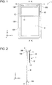
- a lighting device 1 illustrated in Fig. 1 will be described.
- Fig. 1 is a front view illustrating an appearance of a lighting device in a form in which the lighting device is disposed in a window.
- Fig. 2 is a cross-sectional view along a line A-A' of Fig. 1 .
- Fig. 3A is a perspective view illustrating a configuration of a lighting sheet and
- Fig. 3B is a diagram illustrating a cross-sectional shape of a lighting portion.
- Fig. 4 is a perspective view illustrating a configuration of a frame.
- Fig. 5 is a cross-sectional view illustrating a configuration of a lighting unit.
- the lighting device 1 is configured with a lighting unit 10 and a pair of mounting units 11 and 11.
- the lighting unit 10 includes a lighting sheet 12 and a frame (supporting member) 13 supporting the lighting sheet 12.
- the lighting sheet 12 includes a base material 2 having optical transparency, a plurality of lighting portions 3 having optical transparency which is provided in a first surface 2a of the base material 2, and a void portion 4 which is provided between the plurality of lighting portions 3.
- the base material 2 is formed of a thermoplastic polymer or a light permeable resin such as a thermosetting resin, a photopolymerizable resin, or the like.
- a thermoplastic polymer such as a thermosetting resin, a photopolymerizable resin, or the like.
- a light permeable resin acrylic polymers, olefin polymers, vinyl polymers, cellulose polymers, amide-based polymer, fluorine-based polymer, urethane polymer, silicone polymer, an imide-based polymer, or the like can be used.
- a polymethyl methacrylate resin PMMA
- triacetyl cellulose PET
- cycloolefin polymer COP
- PC polyethylene naphthalate
- PEN polyethylene naphthalate
- PES polyethersulfone
- PI polyimide
- the total light transmittance of the base material 2 is preferably 90% or more under the provisions of JIS K7361-1. Therefore, sufficient transparency can be obtained.
- the lighting portion 3 is configured of an organic material having a light transparency and a photosensitivity such as an acrylic resin or an epoxy resin, a silicone resin, or the like.
- a material which is obtained by mixing a polymerization initiator or a coupling agent, a monomer, an organic solvent, or the like can be used.
- the polymerization initiator may include various addition components such as a stabilizer, an inhibitor, a plasticizer, an optical brightener, a mold release agent, a chain transfer agent, other photopolymerizable monomers, or the like.
- materials disclosed in Japanese Patent No. 4129991 can be used.
- the total light transmittance of the lighting portion 3 is preferably 90% or more under the provisions of JIS K7361-1. Therefore, sufficient transparency can be obtained.
- a plurality of lighting portions 3 extends to a longitudinal direction (length direction) of the base material 2 and is provided in an array in a short-hand direction (width direction) of the base material 2.
- the cross-sectional shape configures a prism body having a polygonal shape.
- the lighting portion 3 has, for example, six apexes (q1 to q6) in the cross-sectional shape perpendicular to the longitudinal direction and has a hexagonal shape in which all the inner angle is less than 180°.
- a fourth surface 3D, a fifth surface 3E, and a sixth surface 3F which are positioned lower than the plane surface perpendicular to the first surface 3A passing through the apex q3 function as a reflecting surface reflecting light beams which are incident from the second surface 3B and the third surface 3C.
- the refractive index of the base material 2 is the same as the refractive index of the lighting portion 3.
- the refractive index of the base material 2 is largely different from the refractive index of the lighting portion 3, when the light is incident from the lighting portion 3 to the base material 2, unnecessary refraction or reflection is generated in an interface between the lighting portion 3 and the base material 2. In this case, there is a possibility that the problems are generated such as desired lighting characteristics cannot be obtained and the brightness is deteriorated.
- a plurality of lighting portions 3 can be formed on the base material 2 by using a photolithography.
- the lighting sheet 12 can be manufactured by a method such as a melt extrusion method or a molding extrusion method, and an imprinting method.
- the base material 2 and the plurality of lighting portions 3 are integrally formed by the same resins.
- the frame 13 is formed of an aluminum frame body and supports the lighting sheet 12 in a flat state by surrounding the periphery of the lighting sheet 12.
- a peripheral portion 12C of the lighting sheet 12 By inserting a peripheral portion 12C of the lighting sheet 12 into a groove portion 14 which is formed on an inner wall surface 13C of the frame 13, the lighting sheet 12 has a configuration in which the lighting sheet 12 is stored in the frame 13.
- An opening portion 13A of the frame 13 is formed by an opening area smaller than an area in a plan view of the lighting sheet 12. Therefore, overall the peripheral portion 12C of the lighting sheet 12 can be reliably held in a state where overall the peripheral portion 12C is inserted into the groove portion 14 of the frame 13.
- the lighting unit 10 having such a configuration is disposed in a state where the lighting unit 10 is hanging from the upper portion of the window by the mounting unit 11.
- reference numerical 8 represents a window glass
- reference numerical 108 represents a window sash
- reference numerical 109 represents a window frame.
- each of the mounting units 11 includes an attaching member 15 for attaching the lighting unit 10 to a window frame (mounting target) 109 and a plurality of mounting screws 16, respectively.
- the attaching member 15 is a stainless-steel member and is formed of an L-shaped member in cross section by a frame attachment portion 15A and a window frame attachment portion 15B which are coupled to each other in a vertical posture.
- the mounting screw 16 is crewed on a screw hole 15b which is formed in each of the frame attachment portion 15A and the window frame attachment portion 15B. Accordingly, the attaching member 15 is fixed on the frame 13 and the window frame 109.
- the shape of the attaching member 15 is not limited thereto.
- a pair of attachment portions 13B and 13B is provided on the upper portion.
- screw holes 13b and 13b of the attachment portions 13B and 13B which are provided on the frame 13 side and screw holes 15b and 15b on the attaching member 15 side are crewed to the mounting screw 16 at the same time.
- the lighting unit 10 is mounted on the window frame 109 through the mounting unit 11.
- a fine structure surface 3a of the lighting sheet 12 is in a posture in which the fine structure surface 3a is facing a window glass 8.
- the lighting unit 10 according to the present embodiment is fixed to the window frame 109 through a pair of mounting units 11.
- the number of the mounting units 11 is not limited to two.
- the number of the mounting units 11 can be appropriately changed in accordance with a size of the lighting unit 10 or the like.
- Fig. 6 is a diagram illustrating an example of a room model 1000.
- the room model 1000 is a model that assumes a use of the lighting device 1 in the office, for example.
- a window 1002 in which the lighting device 1 is disposed a room 1003, a ceiling 1003a, a wall 1003b in a side where the solar light is incident, a floor 1003c, a wall 1003d faxing the wall 1003b, a person 1004 who is in a chair, and a person 1005 who is standing on the floor 1003c are illustrated.
- the lighting device 1 is disposed on the top of the indoor side of the window 1002.
- a shape of the cross-section (XZ cross-section) of the room 1003 is a rectangular shape.
- a height H3 of the room 1003 (a height from the floor 1003c to the ceiling 1003a) is 2.7 m, for example.
- a height H2 of the window 1002 is 1.8 m, for example.
- the lighting device 1 is provided in a portion where the human field is not blocked (a portion of 0.7 m from the ceiling 1003a, for example) in the window 1002.
- the height H1 of the lighting device 1 is 0.7 m, for example.
- the room model 1000 it is assumed that a person moves in a place which is away from a distance of about 1 m from the wall 1003b, for example.
- a region D around the window it is assumed that there is no person.
- the region D around the window is 1 m, for example, and it is assumed of a region where the person moves.
- a position of the person's eyes is assumed of 0.8 m to 1.8 m from the floor 1003c, for example.
- a height Ha of the eyes of the person 1005 who is standing on the floor 1003c is 1.8 m, for example.
- a height Hb of the eyes of the person 1004 who is in the chair is 0.8 m, for example.
- a range of a position of the eyes of the person is assumed based on these heights Ha and Hb of the eyes.
- the lighting device 1 has a function allowing external light L to travel toward the ceiling 1003a.
- Light L' travelling toward the ceiling 1003a is reflected by the ceiling 1003a and is radiated indoors, and the light is used instead of the illumination.
- the light L' which has passed through the lighting device 1 is not only travelling toward the ceiling 1003a but also travelling toward the wall 1003d or the floor 1003c.
- a region where the person in the indoor senses the glare is set to a glare area AR.
- the range of the glare area AR is defined based on a region where the person moves and the position of the person's eyes.
- the glare region AR is a region of 0.8 m to 1.8 m from the floor 1003c, for example, in a place which is away from a distance of about 1 m from the wall 1003b, for example.
- Fig. 7 is a diagram for illustrating a lighting function of the lighting device according to a first embodiment.
- Fig. 8 is a diagram illustrating a light path of light passing through the lighting device.
- the incident light is mainly solar light
- the light is mainly incident from obliquely upward of the lighting device 1.
- the light L which is incident to the lighting device 1 through the window glass 8 is refracted and reflected in each of the lighting portions 3 of the lighting sheet 12 and is emitted toward obliquely upward.
- the light which is incident to the lighting sheet 12 is refracted in the third surface 3C of the lighting portion 3 and is travelling to the fifth surface 3E, the light is reflected to the fifth surface 3E and is emitted from the first surface 3A side indoors, and the light is travelling toward the ceiling 1003a of the room 1003 illustrated in Fig. 7 .
- light toward the ceiling 1003a can be relatively increased while reducing the brightness of light toward the glare region AR or the brightness of light toward the floor 1003c. That is, the light L which is incident to the room 1003 through the window 1002 can be radiated toward the ceiling 1003a with good efficiency.
- the light L toward a ceiling 1001 can be radiated to the back of the room 1003 without the persons 1004 and 1005 in the room 1003 sense the glare.
- the light L' reflected on the ceiling 1003a is used instead of the illumination light, and it is brightly illuminated over a wind range of the room 1003.
- an energy saving effect saving the daily energy to be consumed by the illumination system of the room 1003 can be expected.
- Figs. 9A to 9D are diagrams illustrating a disposing example of the lighting device 1.
- the upper diagram is a front view and the lower diagram is a top surface view.
- the lighting device 1 may be disposed such that the entire surface of the lighting unit 10 is facing the window glass 8.
- the lighting device 1 may be attached to an upper portion 109a of the window frame 109 such that the lighting device 1 is disposed at a center in a width direction of the window 1002.
- a part of the frame 13 configuring the lighting unit 10 may dispose the lighting device 1 such that a part of the frame 13 is facing a window sash 108.
- the lighting device 1 may be disposed such that the lighting device 1 is fitted to the inner side of the window frame 109.
- the lighting device 1 is disposed at a position in a distance from the window glass 8.
- the lighting device 1 may be disposed such that the lighting device 1 is adjacent to the window sash 108.
- the lighting device 1 may be disposed such that the lighting device 1 is adjacent to the surface 109c of the indoor side of the window frame 109.
- the lighting device 1 is mounted on the window 1002 by attaching the lighting unit 10 to the window frame 109 through the mounting unit 11.
- the lighting unit 10 is disposed in a posture in which the fine structure surface 3a, in which a plurality of lighting portions 3 is formed in the lighting sheet 12, is facing the window glass 8.
- the lighting device 1 is configured from the mounting unit 11 and the lighting unit 10 and is assembled detachably from the window frame 109 (window 1002) in the mounting unit 11. Therefore, the lighting device 1 can be easily attached or removed to or from the window 1002, compared to the related aspect that the lighting device 1 is directly attached to the window glass 8. Accordingly, maintenance working or exchange working of the lighting unit 10 can be carried out with good efficiency.
- a light weight design can be subjected, compared to the aspect in which the lighting sheet is disposed between two protecting plates. Therefore, the size of the lighting device 1 can be increased and it is possible to rapidly correspond to a request to dispose the lighting device 1 with respect to the big window.
- the disposing position of the lighting unit 10 with respect to the window frame 109 can be freely adjusted. Therefore, by disposing the lighting unit 10 maintain a predetermined distance from the window glass 8, for example, as described in the present embodiment, the fine structure side (a side where the lighting portion 3 is formed) of the lighting sheet 12 can be in a posture in which the fine structure side is toward the window 1002. It is possible to make the fine structure side (a side where the lighting portion 3 is formed) of the lighting sheet 12 to in a posture in which the fine structure side is toward indoors.
- the lighting unit 10 is configured such that the lighting sheet 12 is stored in the frame 13. By fixing the peripheral of the lighting sheet 12 by the frame 13, flatness of the lighting sheet 12 can be maintained. As a result, the good lighting function can be obtained.
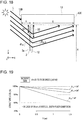
- Fig. 10 is a diagram illustrating an overall configuration of a lighting device according to the second embodiment.
- Fig. 11 is a diagram illustrating a main configuration of the lighting device according to the second embodiment and is a cross-sectional view along a line B-B' of Fig. 10 .
- a basic configuration of the lighting device 20 according to the present embodiment shown in below the description of common portions as the first embodiment above will not be described.
- the same reference numerals are allocated to the common configuration elements of Figs. 1 to 9 .
- the lighting device 20 is configured by including a plurality of lighting units 10, a plurality of coupling members 21, a pair of mounting units 11.
- a structure in which three lighting units 10 (10A, 10B, and 10C) are coupled to each other in the vertical direction through two coupling members 21 is provided.
- the coupling member 21 is configured by a locking portion 22 which is disposed in the lighting unit 10 side which is positioned on the upper side, and a locking portion 23 disposed in the lighting unit 10 side which is positioned on the lower side, among the plurality of lighting units 10A, 10B, and 10C which are adjacent to each other in the vertical direction.
- the locking portion 22 maintains the L-shape in cross-sectional view which is projected to the lower side of the frame 13
- the locking portion 22 extends to the entire the lower side 13c of the frame 13.
- the locking portion 23 maintains the L-shape in cross-sectional view which is projected to the upper side of the frame 13
- the locking portion 23 extends over the entire the upper side 13a of the frame 13.
- the locking portions 22 and 23 are locked in a state where meshing portions 22a and 23a are meshed to each other in the vertical direction. Since the coupling member 21 has the configuration in which the locking portions 22 and 23 are overlapped to each other in the lighting surface (in a YZ plane), the light L is not leaked from the coupling member 21. Thus, as illustrated in Fig. 12 , only the light L which has passed through the lighting sheet 12 of each of the lighting units 10 is incident indoors.
- the lighting device 20 Since the lighting device 20 according to the present embodiment has a coupling structure in which a plurality of lighting units 10 are coupled in the vertical direction, the lighting device 20 can also be easily disposed in the big window. In addition, since a plurality of lighting units 10 can be coupled to each other without the space therebetween, the light L ( Fig. 12 ) is leaked from the space of the coupling member 21 and the person indoors does not sense uncomfortable.
- the coupling member 21 is configured by the locking portions 22 and 23 extending entire the upper side 13a or the lower side 13c of the frame 13.
- the locking portions 22 and 23 may be provided in a part of the upper side 13a or the lower side 13c of the frame 13, respectively.
- Fig. 13 is a diagram illustrating the other coupling structure.
- a configuration in which a plurality of lighting units 10 are coupled in a horizontal direction by the coupling member 21 may be provided. Therefore, as a function of each of the coupling members 21, a function of coupling is not generated such that a space between the adjacent lighting units 10 in the horizontal direction (Y direction), is mainly used.
- the lighting device can be easily disposed in a wider window in the horizontal direction of the room.
- Fig. 14A is a diagram illustrating a configuration of a lighting device according to the third embodiment and Fig. 14B is a cross-sectional view along line C-C' of Fig. 14A .
- Fig. 15A is a diagram illustrating a state where the lighting device according to the third embodiment is used and Fig. 15B is a diagram illustrating a state where the lighting device according to the third embodiment is not used (flip-up state).
- the lighting device 30 is configured by including a lighting unit 31 and a pair of mounting units 32, and as illustrated in Figs. 15A and 15B , the lighting device 30 has a structure that the lighting unit 31 can be flipped toward upward.
- the lighting unit 31 includes the lighting sheet 12 and a frame 35 maintaining the lighting sheet 12 and is fixed to the window frame 109 through the above-described mounting unit 32.
- the mounting unit 32 includes a rotation mechanism 33 and has a structure in which a frame attachment unit 32A is tilted to a window attachment unit 32B by the rotation mechanism 33.
- the rotation mechanism 33 includes a rotating shaft M extending to a direction perpendicular to a sheet surface of Fig. 14B (Y direction) and rotates the frame attachment unit 32A about the rotating shaft M. That is, by rotating the lighting unit 31 (frame 35) which is attached to the frame attachment unit 32A of the mounting unit 32 around the rotating shaft M extending to a direction perpendicular to the disposing direction of the plurality of mounting units 32, the lighting unit 31 can be flipped up toward the ceiling 1003a ( Figs. 15A and 15B ).
- an engaging portion 34 engaging to a clip fastening 1008 which is attached to the ceiling 1003a of the room 1003 in advance is provided.
- the engaging portion 34 is formed into a ring shape, for example, and is locked to a tip end 1008a in a state where the tip end 1008a of the clip fastening 1008 is inserted into an annular hole 34a. Therefore, a state where the lighting unit 31 is flipped up can be maintained.
- a lighting device 100 of the present embodiment it is possible to select the use or not use the lighting device 30 as necessary. That is, it is possible to easily switch ON/OFF of the lighting function.
- Fig. 16 is a front view illustrating a disposing state of a lighting device according to the fourth embodiment.
- Fig. 17A is a cross-sectional view along a line D-D' of Fig. 16 and is a diagram illustrating the lighting device at a normal use
- Fig. 17B is a cross-sectional view along the line D-D' of Fig. 16 and is a diagram illustrating the lighting device at a time of releasing.
- the lighting device 40 is configured of a lighting unit 41 and a mounting mechanism 42 including a pair of mounting units 43 and 44 and the lighting unit 41 is disposed in the window through the mounting mechanism 42.
- the mounting mechanism 42 of the present embodiment includes an opening and closing mechanism which is capable of opening and closing the lighting unit 41 with respect to the window and opens and closes the lighting unit 41 about one mounting unit 43 configuring the attachment mechanism 42.
- the mounting unit 43 includes a rotating shaft N extending to a vertical direction (Z direction) of the window and has a structure in which the mounting unit 43 rotates the lighting unit 41 about the rotating shaft N.
- a mounting unit 44 is configured by including a pair of locking portions 44A and 44B, for example, and holds the lighting unit 41 by locking the locking portion 44A which is provided in the frame 13 side to the locking portion 44B which is provided in the window frame 109 side.
- a pair of magnets may be adopted, for example.
- the lighting unit 41 since the lighting unit 41 has a configuration in which the lighting unit 41 is supported by the window frame 109 by one mounting portion 43, the load of the lighting unit 41 is not applied in the mounting unit 44 side. Accordingly, it is possible to simplify the configuration of the mounting unit 44 side. If the mounting units 43 and 44 can hold the lighting unit 41 parallel and horizontally with respect to the window glass 8, any configuration can also be employed.
- the lighting unit 41 when the cleaning working of the window glass 8 is performed, since the lighting unit 41 may be only open to the indoor side, it is possible to save the trouble of removing the lighting device 40 from the window frame 109.
- the lighting unit 41 since the lighting unit 41 has a configuration in which the lighting unit 41 is rotated about the rotating shaft N, it is not necessary to lift the lighting unit 41 to the ceiling. Therefore, for example, even in a case of a short user, the lighting unit 41 can be easily open.
- Fig. 18 is a diagram for illustrating a relationship between the thickness of the frame and an incident light amount.
- the amount of the light which can be collected indoors through the lighting device has a huge effect on the altitude of the solar.
- a part of the light beams are shielded by the frame 13 of the lighting unit in some cases. That is, by the incident angle ⁇ in of the solar light L, a region in which the solar light is not incident to an upper portion side of the lighting sheet 12 (hereinafter, referred to as a non-incident region S1) is generated in some cases.
- a non-incident region S1 a region in which the solar light is not incident to an upper portion side of the lighting sheet 12
- a non-incident region S2 a region in which the solar light is not incident indoors
- the non-incident region S1 and the non-emitting region S2 can be obtained by the following expressions.
- the disposing position of the lighting sheet 12 in the frame 13 can be expressed such that, in a thickness direction (X direction) of the frame 13, a distance from an incident side end surface 13D side of the frame 13 is defined as Y and a distance from an emission side end surface 13E side of the frame 13 is defined as X.
- Effective incident efficiency (%) in the lighting device and effective emission efficiency (%) can be obtained by the following expressions.
- Effective incident efficiency % H ⁇ S 1 / H
- Effective emission efficiency % H ⁇ S 2 / H
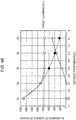
- Fig. 19 is a graph illustrating a relationship between a disposing position Y (cm) of the lighting sheet in a frame when a vertical width inner dimension is set to H (cm) and effective incident efficiency (%) for each of incident angles
- Fig. 20 is a graph illustrating a relationship between a disposing position Y (cm) of the lighting sheet in a frame when a vertical width inner dimension is set to H (cm) and effective emission efficiency (%) for each of emission angles.
- the solar altitude (incident angle ⁇ in of the incident light) is varied in the range of about 31° to 78° in one year.
- the effective incident efficiency is deteriorated and the structure loss becomes greater as the disposing position of the lighting sheet 12 is entered to the inner side of the frame 13, that is, as the length Y between the lighting sheet 12 and the incident side end surface 13D of the frame 13 becomes longer, regardless of the solar altitude (incident angle ⁇ in).
- an effect of the disposing position of the lighting sheet 12 is small compared to the incident side.
- the emission angle ⁇ out of the light to be emitted from the lighting sheet 12 is 30°
- the deterioration degree of the effective emission efficiency becomes greater compared to a case where the emission angle ⁇ out is 5° or 10°. Accordingly, it can be considered that it is affected on the disposing position of the lighting sheet 12 in a greater or lesser degree.
- the structure loss may be much small compared to the incident side and it is considered that it is difficult to effect on the frame 13 and the solar altitude.
- non-incident region S1 which is generated in the incident side of the lighting sheet 12
- Fig. 21A is a front view illustrating a configuration of a lighting device according to the fifth embodiment and Fig. 21B is a cross-sectional view along a line E-E' of Fig. 21A .
- Fig. 22 is a diagram for defining an angle of an inclined surface of a frame.
- Fig. 23 is a graph illustrating a relationship between the angle of the inclined surface of the frame and a solar altitude.
- the lighting device 50 includes a frame 53 including an inclined surface 53a in one surface side facing the window glass 8.
- the inclined surface 53a is formed in the tip end side of an inner peripheral 53d surrounding the periphery of the opening portion 53A and is inclined to the inner side in the thickness direction.
- a configuration in which the inclined surface 53a which is inclined in the incident direction side of the light is provided in a part of the frame 53 with respect to the normal direction of the fine structure surface 3a (main surface) of the lighting sheet 12 is provided.
- an angle ⁇ f formed of an outer peripheral surface 53e and the inclined surface 53a of the frame 53 is set according to an orientation of the window to be disposed or the solar altitude.
- the inclination angle ⁇ f of the inclined surface 53a is set to a range of 30° ⁇ f ⁇ 80 that is an appropriate range.
- the configuration of the present embodiment it is possible to prevent the solar light to be incident to the lighting sheet 12 from being shielded by the frame 53. As a result, it is possible to more collect a lot of the external light beams without affecting on the solar altitude.
- the end surface 53B of the frame 53 is actually bent.
- Fig. 24A is a front view illustrating a configuration of a lighting device according to the sixth embodiment and Fig. 24B is a cross-sectional view along a line F-F' of Fig. 24A .
- Fig. 25 is a diagram of the frame according to the sixth embodiment when viewed from the top side.
- Fig. 26 is a side view of the frame according to the sixth embodiment.
- a lighting unit 61 configuring the lighting device 60 of the present embodiment includes a frame 63 in which a plurality of opening portions (light transmitting portion) 63A are formed in the incident side.
- the plurality of opening portions 63A are formed in the upper side portion 63a at the incident side in the predetermined distance.
- the opening area of each of the storage or the number of the opening portions 63A is appropriately set according to the orientation of the window or the solar altitude.
- the opening portion 63A having a rectangular shape in a plan view is formed in a state where the longitudinal direction is along the width direction (depth direction) of the frame 63. Therefore, it is possible to correspond to the changes in the incident angle ⁇ in of the incident light. That is, even when the incident angle ⁇ in of the incident light to be incident to the lighting unit 61 is changed, as illustrated in Fig. 26 , it is possible to pass through a part of the incident light.
- the lighting sheet 12 which is assembled in the frame 63 is disposed in a position where each of the opening portions 63A of the frame 63 is not overlapped in a plan view. It is preferable that the disposing position of the lighting sheet 12 is set closer to the opening portion 63A as much as possible in the thickness direction of the frame 63.
- the solar altitude incident altitude ⁇ in of the incident light
- a part of the incident light is shielded by the frame 63.
- the lighting sheet 12 By disposing the lighting sheet 12 to the incident end surface side of the frame 63 as much as possible, it is possible to improve the incident efficiency with respect to the lighting sheet 12.
- the fine structure surface 3a is easily scratched, the lighting sheet 12 cannot be disposed to the incident end surface side.
- the lighting device 60 of the present embodiment has a configuration in which the opening portion 63A for allowing the incident light to pass therethrough is provided to the frame 63.
- the opening portion 63A for allowing the incident light to pass therethrough is provided to the frame 63.
- the shape of the opening portion 63A in a plan view is not limited thereto.
- one opening portion (light transmitting portion) 64A may be formed substantially in the longitudinal direction over the entire upper side portion 64a of a frame 64.
- a transparent member 65 is disposed in the opening portion 64A.
- An example of the transparent member 65 includes an acryl plate, a glass plate, a polycarbonate plate, or the like.
- the transparent member 65 may be disposed in each of the opening portions 63A.
- Figs. 28A and 28B are diagrams schematically illustrating a configuration of a lighting unit in a lighting device according to the seventh embodiment, Fig. 28A is a front view, and Fig. 28B is a cross-sectional view along a line I-I' of Fig. 28A .
- Figs. 29A and 29B are diagrams illustrating a state where a modification is generated in the lighting sheet due to changes in a surrounding temperature
- Fig. 29A is a diagram illustrating a state at a normal temperature
- Fig. 29B is a diagram illustrating a state at a high temperature (during expansion changes).
- the lighting device 70 of the present embodiment includes a frame 73 having surplus inner dimension of a groove portion 74 with respect to the other dimension of the lighting sheet 12.
- the frame 73 has a structure in which inner dimensions h3 and h4 of the groove portion 74 holding the lighting sheet 12 is greater than outer dimensions h1 and h2 of the lighting sheet 12 in the vertical direction and the horizontal direction. Therefore, it becomes a configuration which is capable of corresponding to the shape changes in the lighting sheet 12 expanding due to the surrounding temperature changes.
- the opening potion 73A of the frame 73 is formed in an opening area smaller than the area of the lighting sheet 12 in the plan view.
- the lighting sheet 12 is maintained during a normal temperature in a state where the lighting sheet 12 has surplus with respect to the groove portion 74 of the frame 73.
- the lighting sheet 12 is held by the frame 73 in a state where a lower end surface 12d abuts to a bottom surface 74c of the groove portion 74 of the frame 73 and a space is provided between a side end surface 12e other than the lower end surface 12d and the bottom surface 74c of the groove portion 74. Therefore, the temperature of the surrounding environment becomes higher, and even in a case where the lighting sheet 12 is dilation deformed in a plane direction as illustrated in Fig. 29B , the peripheral portion 12C of the lighting sheet 12 maintains the flat posture without bending due to the abutting the peripheral portion 12C of the lighting sheet 12 to the bottom surface 74c of the groove portion 74.
- Fig. 30 is a diagram illustrating a relationship between shape changes in associated with the temperature changes and an average linear expansion coefficient.
- a main material to be used in the lighting sheet 12 As a main material to be used in the lighting sheet 12, acryl, PET, and PC are included. An average linear expansion coefficient of each material is about 7 (10 -5 /°C).
- a margin of 4.2 mm/m or more is provided to the inner shape dimension of the groove portion 74 with respect to the outer shape dimension of the lighting sheet 12. Therefore, in a case of the high temperature (80°C), it is possible to prevent the lighting sheet 12 from being abutted to the inner side (bottom surface 14c of the groove portion 14) of the frame 73.
- the lighting sheet 12 is designed so as to hold the lighting sheet 12 without space in the frame 73, it is not possible to correspond to the expansion change in the lighting sheet 12 and the lighting sheet 12 cannot be held in a flat state. Accordingly, in consideration of the temperature change in the surrounding environment which is capable of predicting in advance, by setting the dimension of the groove portion 74 of the frame 73 according to an expansion coefficient of the lighting sheet 12, it is possible to successfully hold the lighting sheet 12 regardless of the temperature changes due to the season or a disposing place.
- Fig. 31A is a front view illustrating an overall configuration of a lighting device according to the eighth embodiment.
- Fig. 31B is a diagram illustrating a disposing state of a temperature detecting material.
- a temperature detecting member (member for adjusting a temperature) 81 is provided in an inner portion of the frame 13 holding the lighting sheet 12.
- the temperature detecting member 81 displays the temperature, irreversibly.
- a detection unit 82 which is formed of a plurality of regions Sa to Se which are sequentially discolored according to the temperature is included, and an irreversible detection seal in which when the color of the detection seal is changed once, the color is not returned to the original color can be adopted.
- the temperature detecting member 81 of the present embodiment is attached to the bottom surface 14c of the groove portion 14 in the frame 13. However, it is not limited thereto.
- the temperature detecting member 81 is attached to a surface of the outer side of the frame so as to cause the user to easily recognize the temperature detecting member 81.
- Fig. 32 is a plan view illustrating a main configuration of a lighting unit in a lighting device according to the ninth embodiment.
- a lighting device 90 (lighting unit 91) of the present embodiment includes a frame 93 in which a part of side portions 93a, 93b, 93c, and 93d is formed from a buffer material 95.
- the buffer material 95 is disposed between the pair of frame members 94.
- a soft material may be an elastic material such as rubber
- the entire the frame 93 is not configured by a metal member, and a part thereof is configured by including the buffer material 95. Therefore, it is possible to relieve a distortion of the peripheral members due to the thermal expansion or contraction of the frame 93.
- each of the side portions 93a, 93b, 93c, and 93d configuring the frame 93 includes the buffer material 95, respectively, it is possible to correspond to the shape changes in the frame 93 in the vertical direction and the horizontal direction.
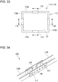
- Fig. 33 is a plan view illustrating a main configuration of a lighting unit in a lighting device according to a tenth embodiment.
- Fig. 34 is a perspective view for illustrating a configuration of a frame of the tenth embodiment.
- a lighting device 110 (lighting unit 111) of the present embodiment has a configuration in which the size of a frame 113 holding the lighting sheet 12 can be freely adjusted.
- an expansion portion 115 is provided in each of side portions 113a, 113b, 113c, and 113d which form a frame shape and the frame 113 is capable of expansion and contraction in a direction along the outer periphery of the frame 113.
- the expansion portion 115 includes a coupling tool 116 for coupling a pair of frame members 113A and 113A and a pair of screws 117 and 117 for fixing each of frame members 113A and the coupling tool 116, respectively.
- a coupling tool 116 for coupling a pair of frame members 113A and 113A and a pair of screws 117 and 117 for fixing each of frame members 113A and the coupling tool 116, respectively.
- a plurality of position adjusting holes 6a which is capable of adjusting of the fixing position of each of the frame member 113A and 113A is formed, and by crewing the screw 117 and the screw hole (not illustrated) of at least of the position adjusting hole 6a and the frame members 113A and 113A side, the coupling tool 116 is coupled to the frame members 113A and 113A.
- the expansion portion 115 of the present embodiment it is possible to adjust the size of the frame 113 by changing the fixing position of the frame members 113A and 113A with respect to the coupling tool 116, instead of the position adjusting hole 6a for screwing in accordance with the size of the window.
- the lighting sheet 12 when the lighting sheet 12 is held in the frame 113, for example, since the lighting sheet 12 is held without bending the lighting sheet 12, the working for assembly the lighting sheet 12 to the frame 113 becomes easier.
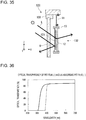
- Fig. 35 is a cross-sectional view illustrating a schematic configuration of a lighting device of the eleventh embodiment.
- the lighting sheet 12 and an ultraviolet protection layer 121 which is provided in an incident light side of the lighting sheet 12 include a lighting unit 122 which is stored in the frame 13.
- the ultraviolet protection layer 121 is a film through which a visible light ray is passed by substantially protecting the ultraviolet ray.
- the ultraviolet protection layer 121 By disposing the ultraviolet protection layer 121 to the light incident side of the lighting sheet 12, it is possible to suppress a deterioration of the lighting sheet 12 due to the ultraviolet. Therefore, the lighting sheet 12 can be used for a long periods, and it is not require the maintenance such as the replacing.
- the ultraviolet protection layer 121 by covering the fine structure surface side of the lighting sheet 12, the fine structure can be protected and the cleaning or the like is also easily performed. In addition, burning (fading) of the furniture or the wall material indoors is suppressed.
- Fig. 36 is a graph illustrating a light transmittance of a PET film in which a UV protection measure is subjected (a graph indicated by a broken line) and a light transmittance in the PET film in which the UV protection measure is not subjected (a graph indicated by a solid line).
- a horizontal axis of a graph in the drawing represents a wavelength (nm) and a vertical axis represents a light transmittance (%).
- a UV absorptive material which absorbs the light having a wavelength of 300 nm to 380 nm may be mixed to a PET film.
- a transmission spectrum of the ultraviolet protection layer 121 has characteristics as illustrated in a graph of the broken line of Fig. 36 .
- the PET film to which the UV absorptive material is mixed is adopted as the ultraviolet protection layer 121 in the present embodiment and the ultraviolet protection layer 121 is disposed on the light incident side of the lighting sheet 12. Therefore, the deterioration (fading) in the lighting sheet 12 is suppressed and the lighting device 120 which can withstand long-term use can be obtained.
- Fig. 37 is a cross-sectional view illustrating a configuration of a lighting device according to the twelfth embodiment.
- Fig. 38 is a perspective view illustrating an aspect of a light diffusion layer.
- the lighting sheet 12 and a light diffusion layer 131 include a lighting unit 132 which is stored in the frame 13.
- the light diffusion layer 131 is disposed in the light emission side of the lighting sheet 12 and may diffuse and emit the light from the lighting sheet 12 indoors.
- the light diffusion layer 131 of the present embodiment has anisotropism to the light diffusion properties and is configured so as to show the high light diffusion properties in the Y direction (horizontal direction).
- the light diffusion layer 131 is formed of a lenticular lens structure 36 which is configured by a plurality of convex lens portions (convex portion) 37.
- Each of the plurality of convex lens portions 37 extends in a Z direction (vertical direction) and the convex lens portions 37 are arranged in parallel in the Y direction.
- the light diffusion layer 131 having such a structure is provided in a posture that a rear surface 36b side of the lenticular lens structure 36 is facing the lighting sheet 12.
- a lens surface of 37a of the convex lens portion 37 has a curvature in a horizontal plane and has no curvature in the vertical direction. Therefore, the convex lens portion 37 has high light diffusion properties in the Y direction (horizontal direction) and has no light diffusion properties in the vertical direction. Accordingly, the light which is incident to the light diffusion layer 131 is greatly diffused in the Y direction (horizontal direction), when the light is emitted from the convex lens portion 37 and the diffused light is emitted without diffusing in the vertical direction.
- Fig. 39 is a graph illustrating light scattering properties of the light diffusion layer.
- Fig. 39 is a graph in which measurement light is radiated from a perpendicular direction with respect to the light diffusion layer, and regarding the light intensity which is obtained by receiving the light by moving a photoreceiver at an opposite side, a peak value is standardized as 1.
- a weak scattering film having about several degrees to 20 degrees of the full width at half maximum is preferable so as not to deteriorate the directional characteristics of the light illuminating in the ceiling direction.
- the light illuminating in the ceiling direction is diffused in a direction of the person in the floor side indoors, and the brightness of the light to be viewed by the person becomes greater compared to a case of the high directional characteristics. Therefore, as the light diffusion layer, an anisotropic scattering layer, in which the light is specifically diffused in the horizontal direction and the light is not nearly diffused in the vertical direction, is preferable.
- the light diffusion layer 131 in a case where the full width at half maximum of front measuring light passing through the light diffusion layer 131 is about 5 degrees, the light is diffused at 17 degrees of the full width at half maximum in the horizontal direction, the diffusion of the light in the vertical direction becomes 5 degrees of the full width at half maximum, and almost light is not diffused.
- the light from the lighting sheet 12 can be specifically diffused and emitted in the horizontal direction by the light diffusion layer 131.
- the form other than the above-described form may be used.
- a light diffusion layer 301 having a streak-like fine shape including a plurality of convex portions 133 extending in one direction may be used in one surface 311a side of a supporting base material 311.
- the convex portions 133 extending roughly in the short-hand direction (Z direction) are arranged in the longitudinal direction (Y direction) of the supporting base material 311 and has a so-called pseudo-stripe structure.
- the light diffusion layer 301 having the pseudo-stripe structure in which the light diffusion properties is provided in one direction (Y direction) and the light diffusion properties is rarely provided in the other direction (Z direction) perpendicular to the one direction.
- Figs. 41A and 41B are schematic diagrams of the room model for illustrating light diffusion properties of a lighting slat
- Fig. 41A is a diagram of a room when viewed from the top
- Fig. 41B is a diagram of a room when viewed from the side.
- the external light lighted to the lighting sheet 12 is straightly incident to the room 1003. Accordingly, a day when the solar light is directed to the lighting device such as a clear day is depending on the solar altitude.
- the solar light which is refracted by the lighting sheet 12 is reflected and the light ray to be radiated to the ceiling originally is viewed by the person, the light is glare and it is recognized as the uncomfortable glare.
- the solar light can be set as a point light source having extremely high brightness and the directional characteristics, in a case where the light is straightly incident, the light ray is incident to the room while having the characteristics such as the high brightness and high directional characteristics. If this light is entered to the eyes of the person 1004 in the room, the person feels extremely glare.
- the light diffusion layer 131 is included as a purpose of preventing the glare. It is preferable that the external light including the solar light which is incident from the outside is diffused before the external light is incident indoors, is converted into soft light, and is provided. As illustrated in Fig. 41A , by specifically diffusing the light in the horizontal direction of the room 1003 by the light diffusion layer 131, the brightness in the specific direction (vertical direction) is lowered and the glare rarely occurs, as illustrated in Fig. 41B .
- the amount of the light reached the back of the room is reduced.
- the spread in the transverse direction can be obtained. By spreading the light in the transverse direction, even in a case of the small window, it is possible to bright entire the room from the end to the end (transverse direction).
- the solar light is entered diagonally, it is possible to brighten up the center of the room.
- Fig. 42 is a perspective view illustrating a configuration of a lighting device according to the thirteenth embodiment.
- Fig. 43 is a cross-sectional view illustrating the configuration of the lighting device according to the thirteenth embodiment.
- a lighting device 140 of the present embodiment has a configuration further including a light shielding unit 142 at the lower side of a lighting unit 141.
- the light shielding unit 142 is attached to the lower portion of the lighting unit 10 through a pair of attachment portions 18 and 18.
- a window shade 401 is used as the light shielding unit 142.
- the window shade 401 includes a plurality of lighting slats 402 which are disposed in an array at a predetermined distance, a tilting mechanism (not shown) supporting the plurality of lighting slats in a tilting and free manner to each other, and a storage mechanism 408 which folds the plurality of lighting slats 402 which are coupled to each other to be able entering by the tilting mechanism (not shown) and stores the folded lighting slats 402.
- Such a window shade 401 is fixed by attaching the storage mechanism 408 to the lower portion of the frame 13 of the lighting unit 141 by the pair of the attachment portions 18 and 18.
- the window shade 401 is provided so as to cover one surface of the window from the viewpoint of the privacy or the viewpoint of the light shielding purpose, when closing the window shade 401, entire the room becomes darker. Accordingly, eventually, it is necessary to turn on the illumination, although in the daylight.
- the lighting device 140 of the present embodiment has a configuration including a shielding vision function of the light shielding unit 142 and the lighting function of the lighting unit 141, even in a state where the window shade 401 is closed, the external light can be radiated indoors by lighting the external light by the lighting unit 141 and the indoor is not darkened.
- the closing state of the window shade 401 the brightness of the indoor can be operated. As a result, it is not necessary to turn on a light bulb in the indoor in day time. Accordingly, the power to be consumed by the lighting equipment in the daylight can be reduced.
- the window shade 401 is used as the first light shielding unit 142.
- a roll curtain or the like may be used.
- the lighting device 140 of the present embodiment can be manufactured by the same depth dimension as that of the window shield or the roll curtain, it is not required to protect the disposing place indoors newly, and it can be used in the same way as conventional.
- Fig. 44 is a diagram illustrating a configuration of a lighting device according to the fourteenth embodiment.
- Figs. 45A to 45C are diagrams for illustrating a function of the lighting device according to the fourteenth embodiment
- Fig. 45A is a diagram illustrating a state where a window shade is open
- Fig. 45B is a diagram illustrating a state where the window shade is open
- Fig. 45C is a diagram illustrating a state where a window shade is closed.
- a lighting device 150 of the present embodiment is configured by including the lighting unit 141, a first light shielding unit 142 which is provided at the lower portion of the lighting unit 141, and a second shielding unit 143 which is provided at the light emission side of the lighting unit 141.
- the first light shielding unit 142 is the above-described window shade 401 and is attached to the lower portion of the frame 13 of the lighting unit 141 through an attachment portion 145.
- the second shielding unit 143 is a window shade 403 which forms the same configuration as that of the window shade 401 and is attached to the window frame 109 at the light emission side of the lighting unit 141 through the mounting unit 11.
- the storage mechanism 408 of the second shielding unit 143 may be integrally configured with the frame 13 of the lighting unit 141. In this manner, since the number of the mounting units 11 can be reduced, it does not take the trouble of the mounting.
- the configuration of the present embodiment it is possible to make the function of the lighting unit 141 to efficient as necessary. That is, as illustrated in Fig. 45A , by setting the window shade 403 which is provided in the light emission side of the lighting unit 141 to the closing state, or, as illustrated in Fig. 45B , storing the entire slats 402 of the window shade 403 to the storage mechanism 408, the light which is lighted by the lighting unit 141 can be collected indoors. On the other hand, as illustrated in Fig. 45C , by closing the window shade 403, it is possible to shield the light from the lighting unit 141.
- Fig. 46 is a diagram illustrating a room model 2000 including the lighting device and an illumination dimming system and is a cross-sectional view along a line J-J' of Fig. 47.
- Fig. 47 is a plan view illustrating a ceiling of the room model 2000.
- a ceiling material configuring a ceiling 2003a of a room 2003 to which the external light is incident may have the high light diffusion properties.
- a light reflecting ceiling material 2003A is disposed in the ceiling 2003a of the room 2003 as the ceiling material having the light reflecting properties. Since the light reflecting ceiling material 2003A is aimed to promote entering the external light from a lighting device 2010 which is disposed on a window 2002 to the back indoors, the light reflecting ceiling material 2003A is disposed in the ceiling 2003a at the window. Specifically, the light reflecting ceiling material 2003A is disposed at a predetermined region E (a region which is away from a distance of about 3 m from the window 2002) of the ceiling 2003a.
- the light reflecting ceiling material 2003A serves to guide the external light which is induced indoors through the window 2002, in which the lighting device 2010 (any one of the lighting devices described above) of the invention is disposed, to the back of the indoor with good efficiency.
- the external light which is induced from the lighting device 2010 toward the ceiling 2003a indoors is reflected to the light reflecting ceiling material 2003A, and by illuminating a top surface of a desk 2005a of a desk 2005 which is placed on the back of the indoor by changing the direction of the external light, it is possible to exhibit the effect for brightening the top surface of a desk 2005a.
- the light reflecting ceiling material 2003A may have diffusion reflectivity and may have specularity.
- the both characteristics is appropriately combined.
- the most of the light beams which are incident to the indoor by the lighting device 2010 of the present invention is toward the ceiling adjacent to the window 2002.
- the amount of the light around the window 2002 is sufficient, in some cases. Accordingly, by using the above-described light reflecting ceiling material 2003A, the light which is incident to the ceiling (region E) around the window can be separated to the back indoors which has small light amount compared to the window side.
- the light reflecting ceiling material 2003A is prepared, for example, by performing an embossing process by irregularities of about several tens of the microns on the metal plate such as aluminum, and by evaporating a metal thin film such as aluminum to the surface of a resin substrate to which the same irregularities are formed.
- the irregularities which are formed by embossing process are formed by a curved surface in which the cycle is long.
- the embossed shape to be formed in the light reflecting ceiling material 2003A it is possible to suppress the light distribution characteristics of the light or the distribution of the light indoors.
- the embossing process is carried out into a strip shape extending to the back of the indoor
- the light reflected to the light reflecting ceiling material 2003A is spread in the horizontal direction (a direction intersecting the longitudinal direction of the irregularities) of the window 2002.
- the size or the direction of the window 2002 of the room 2003 is limited, by using the properties, the light is dispersed to the horizontal direction by the light reflecting ceiling material 2003A and can be reflected toward the direction of the back indoors.
- the lighting device 2010 of the present invention is used as a part of the illumination dimming system of the room 2003.
- the illumination dimming system is, for example, configured from a configuring member of the entire room including the lighting device 2010, a plurality of indoor illumination device 2007, a solar insolation adjustment device 2008 which is disposed in the window, control systems thereof, the light reflecting ceiling material 2003A which is disposed in the ceiling 2003a.
- the lighting device 2010 is disposed at the upper portion side, and the solar insolation adjustment device 2008 is disposed at the lower portion side.
- the solar insolation adjustment device 2008 the window shade is disposed. However, it is not limited thereto.
- the plurality of indoor illumination devices 2007 is disposed in the room 2003 in a lattice pattern in the horizontal direction of the window 2002 (Y direction) and the depth direction indoors (X direction).
- the plurality of indoor illumination devices 2007 configures the entire illumination system of the room 2003 together with the lighting device 2010.
- the ceiling 2003a of the office having a length L1 of the window 2002 in the horizontal direction (Y direction) is 18 m and a length L2 of the room 2003 in the depth direction (X direction) is 9 m is illustrated.
- the indoor illumination device 2007 is disposed in a lattice pattern at a distance P of 1.8 m, respectively, in the transverse direction (Y direction) and the depth direction (X direction) of the ceiling 2003a.
- 50 indoor illumination devices 2007 are arranged in 10 columns (Y direction) x 5 rows (X direction).
- the indoor illumination device 2007 includes indoor lighting equipment 2007a, a brightness detecting unit 2007b, and a control unit 2007c, and has a configuration in which the brightness detecting unit 2007b and control unit 2007c are integrally formed in the indoor lighting equipment 2007a.
- the indoor illumination device 2007 may include a plurality of the indoor lighting equipment 2007a and the brightness detecting units 2007b. However, the brightness detecting unit 2007b is provided one by one with respect to each of the indoor lighting equipment 2007a. The brightness detecting unit 2007b receives the reflected light of the surface to be illuminated by the indoor lighting equipment 2007a to detect the illuminance of the surface to be illuminated. Here, the illuminance of the top surface of a desk 2005a of the desk 2005 placed indoors is detected by the brightness detecting unit 200b.
- Control units 2007c which are provided in each of the indoor illumination devices 2007 one by one is connected to each other.
- Each indoor illumination device 2007 performs a feedback control adjusting the light output of each of LED lamps indoors lighting equipment 2007a by the control units 2007c which are connected to each other, such that the illuminance of the top surface of a desk 2005a to be detected by each brightness detecting unit 2007b to be a certain target illuminance L0 (for example, average illuminance: 750 lx).
- Fig. 48 is a graph illustrating a relationship between an illuminance of light (natural light) lighted indoors due to the lighting device and an illuminance (illumination dimming system) due to an indoor illumination device.
- an illuminance of the surface of the desk caused by the light lighted by the lighting device 2010 is high as approaching nearer to the window and the effect is degraded more distant from the window.
- the illumination distribution to the depth direction of the room is generated by the natural light from the window in the day time.
- the lighting device 2010 of the present invention is used together with the indoor illumination device 2007 which compensates the indoor illumination distribution.
- the indoor illumination device 2007, which is disposed in the indoor ceiling, detects the average illuminance lower each of the devices by the brightness detecting unit 2007b and is turned on by dimming controlling such that the illuminance of the top surface of the desk in entire the room to be a certain target illuminance L0.
- the lighting device 2010 and the illumination dimming system indoor illumination device 2007
- light can be reached in the back indoors
- the brightness indoors can further be improved, and a sufficient illuminance of a surface of a desk can be secured in terms of the office across the room. Accordingly, a bright light environment which is more stabilized without affecting due to the season or the weather can be obtained.
- the lighting portion 3 is not limited to a lighting portion which is configured by the above-described prism body having a hexagonal shape in cross section and may be a lighting portion which is configured by a prism body having a having a triangular shape in cross section, a trapezoidal shape (rectangular shape) in cross section, or a pentagon shape in cross section and can be appropriately modified.
- An aspect of the present invention can be adopted to a lighting device which collects outdoor natural light (solar light) indoors with good efficiency, can cause a person in the indoor to sense brightly the back of the indoor without glare, and can be easily removed from the mounting target, or the like.
- outdoor natural light solar light
Landscapes
- Engineering & Computer Science (AREA)
- Physics & Mathematics (AREA)
- General Engineering & Computer Science (AREA)
- Life Sciences & Earth Sciences (AREA)
- Sustainable Development (AREA)
- Optics & Photonics (AREA)
- General Physics & Mathematics (AREA)
- Architecture (AREA)
- Structural Engineering (AREA)
- Health & Medical Sciences (AREA)
- Toxicology (AREA)
- Civil Engineering (AREA)
- Non-Portable Lighting Devices Or Systems Thereof (AREA)
- Fastening Of Light Sources Or Lamp Holders (AREA)
- Securing Globes, Refractors, Reflectors Or The Like (AREA)
Abstract
Description
- The present invention relates to a lighting device.
- This application claims priority based on Japanese Patent Application No.
2014-099597, filed on May 13, 2014 - In the related art, in a lighting sheet to be applied to a window or the like, most of the lighting sheets have a plurality of fine structure portions serving a lighting function. Most of the lighting sheets adopt a form in which the lighting sheet is directly attached to a window glass. In a case of the form in which the lighting sheet is attached to the window glass, it is difficult to construct or remove the lighting sheet. In addition, in a case where the lighting sheet is attached in a form that a side in which the fine structure portion is provided is facing the window glass, there is a problem in that the fine structure portions is buried in an adhesive, thereby the lighting function is deteriorated.
- As a method for solving the problem, a method in which a lighting sheet is disposed between two protecting plates and the lighting sheet is attached to a window glass through an adhesive which is provided at least one side of the protecting plate is proposed (for example, PTL 1). According to the configuration, the fine structure portion is not buried in the adhesive for attaching the lighting sheet to the window glass.
- In
PTL 1, a window system including a first protecting plate and a second protecting plate including a lighting sheet is intended and the first protecting plate and the second protecting plate are fixed so that the lighting sheet is plated inward. - In addition, a structure in which a plurality of an adhesion dedicated projections is provided on a fine structure surface side of the lighting sheet and a gap between the adhesive or the window glass and the fine projection is set to a hollow by attaching the lighting sheet to the window glass through the projections is also proposed.
- PTL 1: Japanese Unexamined Patent Application Publication No.
2013-235860 - However, since any configuration of
PTL 1 above is also a type that the lighting device is directly attached to the window glass, it is not a structure that the lighting device can be easily removed from a window (window glass). In addition, since a plurality of protecting plates which has the same area as that of the lighting sheet is required, the weight thereof increases. - An aspect of the present invention was accomplished in light of the above problems of the conventional technique. An object of the present invention is to provide a lighting device which suppresses an increase in the weight and which can be easily removed from the window (window glass).
- A lighting device according to an aspect of the present invention includes a lighting unit; and a mounting unit for mounting the lighting unit on a mounting target, in which the lighting unit includes a lighting sheet and a supporting member supporting the lighting sheet in at least a portion of a peripheral portion of the lighting sheet, in which the lighting sheet includes a base material having optical transparency, a plurality of lighting portions having optical transparency which are provided in a first surface of the base material, and a void portion which is provided between the plurality of lighting portions, and in which a part of the side surface of the lighting portion facing the void portion serves as a reflecting surface reflecting light which is incident to the lighting portion.
- The lighting device according to the aspect of the present invention may have a configuration in which the supporting member is formed of a frame body, and the frame body supports the lighting sheet in a form that the frame body surrounds the peripheral portion of the lighting sheet.
- The lighting device according to the aspect of the present invention may have a configuration in which the frame body has a groove portion in an inner wall surface in which the lighting sheet is disposed and supports the lighting sheet by inserting the peripheral portion of the lighting sheet into the groove portion.
- The lighting device according to the aspect of the present invention may have a configuration in which a gap is provided between a bottom surface of the groove portion and the lighting sheet.
- The lighting device according to the aspect of the present invention may include a plurality of the lighting units and may have a configuration in which a coupling member coupling the lighting units is provided in the supporting member.
- The lighting device according to the aspect of the present invention may have a configuration in which an inclined surface which is inclined to an incident direction side of light with respect to a main surface of the lighting sheet in a normal direction is provided in a part of the supporting member.
- The lighting device according to the aspect of the present invention may have a configuration in which a light transmitting portion is provided in a part of the supporting member.
- The lighting device according to the aspect of the present invention may have a configuration in which a rotation mechanism which rotates the lighting unit around a rotating shaft which is parallel to a main surface of the lighting sheet is included.
- The lighting device according to the aspect of the present invention may have a configuration in which the mounting unit includes a plurality of mounting units which are arranged in one direction, and the rotation mechanism rotates the lighting unit around the rotating shaft extending in a direction parallel to an arrangement direction of the plurality of mounting units.
- The lighting device according to the aspect of the present invention may have a configuration in which the mounting unit includes a plurality of mounting units which are arranged in one direction, at least one mounting unit among the plurality of mounting units is detachable from the lighting unit, and the rotation mechanism rotates the lighting unit around the rotating shaft extending in a direction parallel to an arrangement direction of the plurality of mounting units.
- The lighting device according to the aspect of the present invention may have a configuration in which an elastic body is provided in at least a part of the supporting member.
- The lighting device according to the aspect of the present invention may have a configuration in which the supporting member is expandable in a direction along an outer periphery of the lighting sheet.
- The lighting device according to the aspect of the present invention may have a configuration in which a member for managing a temperature is provided in the lighting unit. Advantageous Effects of Invention
- As described above, according to the aspect of the present invention, it is possible to provide a lighting device which brings outdoor natural light (solar light) indoors with good efficiency, can cause a person indoors to sense brightly the indoor without glare, and can be easily removed from the mounting target.
-
- [
Fig. 1] Fig. 1 is a front view illustrating an appearance of a lighting device in a form in which the lighting device is disposed in a window. - [
Fig. 2] Fig. 2 is a cross-sectional view along a line A-A' ofFig. 1 . - [
Fig. 3A] Fig. 3A is a perspective view illustrating a configuration of a lighting sheet. - [
Fig. 3B] Fig. 3B is a diagram illustrating a cross-sectional shape of a lighting portion. - [
Fig. 4] Fig. 4 is a perspective view illustrating a configuration of a frame. - [
Fig. 5] Fig. 5 is a cross-sectional view illustrating a configuration of a lighting unit. - [
Fig. 6] Fig. 6 is a diagram illustrating an example of a room model. - [
Fig. 7] Fig. 7 is a diagram for illustrating a lighting function of the lighting device according to a first embodiment. - [
Fig. 8] Fig. 8 is a diagram illustrating a light path of light passing through the lighting device. - [
Fig. 9A] Fig. 9A is a first diagram illustrating a disposing example of the lighting device. - [
Fig. 9B] Fig. 9B is a second diagram illustrating a disposing example of the lighting device. - [
Fig. 9C] Fig. 9C is a third diagram illustrating a disposing example of the lighting device. - [
Fig. 9D] Fig. 9D is a fourth diagram illustrating a disposing example of the lighting device. - [
Fig. 10] Fig. 10 is a diagram illustrating an overall configuration of a lighting device according to a second embodiment. - [
Fig. 11] Fig. 11 is a diagram illustrating a main configuration of the lighting device according to the second embodiment and is a cross-sectional view along a line B-B' ofFig. 10 . - [
Fig. 12] Fig. 12 is a diagram for illustrating the lighting function of the lighting device. - [
Fig. 13] Fig. 13 is a diagram illustrating the other coupling structure. - [
Fig. 14A] Fig. 14A is a front view illustrating a configuration of a lighting device according to a third embodiment. - [
Fig. 14B] Fig. 14B is a cross-sectional view along line C-C' ofFig. 14A . - [
Fig. 15A] Fig. 15A is a diagram illustrating a state where the lighting device according to the third embodiment is used. - [
Fig. 15B] Fig. 15B is a diagram illustrating a state where the lighting device is not used (flip-up state). - [
Fig. 16] Fig. 16 is a front view illustrating a disposing state of a lighting device according to a fourth embodiment. - [
Fig. 17A] Fig. 17A is a cross-sectional view along a line D-D' ofFig. 16 and is a diagram illustrating the lighting device at a normal use. - [
Fig. 17B] Fig. 17B is a cross-sectional view along the line D-D' ofFig. 16 and is a diagram illustrating the lighting device at a time of releasing. - [
Fig. 18] Fig. 18 is a diagram for illustrating a relationship between the thickness of the frame and an incident light amount. - [
Fig. 19] Fig. 19 is a graph illustrating a relationship between a disposing position Y (cm) of the lighting sheet in a frame when a vertical width inner dimension is set to H (cm) and effective incident efficiency (%) for each incident angle. - [
Fig. 20] Fig. 20 is a graph illustrating a relationship between a disposing position Y (cm) of the lighting sheet in a frame when a vertical width inner dimension is set to H (cm) and effective emission efficiency (%) for each emission angle. - [
Fig. 21A] Fig. 21A is a front view illustrating a configuration of a lighting device according to a fifth embodiment. - [
Fig. 21B] Fig. 21B is a cross-sectional view along a line E-E' ofFig. 21A . - [
Fig. 22] Fig. 22 is a diagram for defining an angle of an inclined surface of a frame. - [
Fig. 23] Fig. 23 is a graph illustrating a relationship between the angle of the inclined surface of the frame and a solar altitude. - [
Fig. 24A] Fig. 24A is a front view illustrating a configuration of a lighting device according to a sixth embodiment. - [
Fig. 24B] Fig. 24B is a cross-sectional view along a line F-F' ofFig. 24A . - [
Fig. 25] Fig. 25 is a diagram of the frame according to the sixth embodiment when viewed from the top side. - [
Fig. 26] Fig. 26 is a side view of the frame according to the sixth embodiment. - [
Fig. 27] Fig. 27 is a diagram illustrating a modification example of the frame according to the sixth embodiment. - [
Fig. 28A] Fig. 28A is a plan view schematically illustrating a configuration of a lighting unit in a lighting device according to a seventh embodiment. - [
Fig. 28B] Fig. 28B is a diagram schematically illustrating a configuration of the lighting unit in the lighting device according to the seventh embodiment and is a cross-sectional view along a line I-I' ofFig. 28A . - [
Fig. 29A] Fig. 29A is a diagram illustrating a state where a modification is generated in the lighting sheet due to changes in a surrounding temperature and is a diagram illustrating a state at a normal temperature. - [
Fig. 29B] Fig. 29B is a diagram illustrating a state where a modification is generated in the lighting sheet due to changes in a surrounding temperature and is a diagram illustrating a state at a high temperature (during expansion changes). - [
Fig. 30] Fig. 30 is a diagram illustrating a relationship between shape changes in associated with the temperature changes and an average linear expansion coefficient. - [
Fig. 31A] Fig. 31A is a front view illustrating an overall configuration of a lighting device according to an eighth embodiment. - [
Fig. 31B] Fig. 31B is a diagram illustrating a disposing state of a temperature detecting material. - [
Fig. 32] Fig. 32 is a plan view illustrating a main configuration of a lighting unit in a lighting device according to a ninth embodiment. - [
Fig. 33] Fig. 33 is a plan view illustrating a main configuration of a lighting unit in a lighting device according to a tenth embodiment. - [
Fig. 34] Fig. 34 is a perspective view for illustrating a configuration of a frame of the tenth embodiment. - [
Fig. 35] Fig. 35 is a cross-sectional view illustrating a schematic configuration of a lighting device of an eleventh embodiment. - [
Fig. 36] Fig. 36 is a graph illustrating a light transmittance of a PET film in which a UV protection measure is subjected (a graph indicated by a broken line) and a light transmittance in the PET film in which the UV protection measure is not subjected (a graph indicated by a solid line). - [
Fig. 37] Fig. 37 is a cross-sectional view illustrating a configuration of a lighting device according to a twelfth embodiment. - [
Fig. 38] Fig. 38 is a perspective view illustrating a form of a light diffusion layer. - [
Fig. 39] Fig. 39 is a graph illustrating light scattering properties of the light diffusion layer. - [
Fig. 40] Fig. 40 is a perspective view illustrating the other form of the light diffusion layer. - [
Fig. 41A] Fig. 41A is a schematic diagram of the room model for illustrating light diffusion properties of a lighting slat and is a diagram of a room when viewed from the top. - [
Fig. 41B] Fig. 41B is a schematic diagram of the room model for illustrating light diffusion properties of a lighting slat and is a diagram of a room when viewed from the side. - [
Fig. 42] Fig. 42 is a perspective view illustrating a configuration of a lighting device according to a thirteenth embodiment. - [
Fig. 43] Fig. 43 is a cross-sectional view illustrating the configuration of the lighting device according to the thirteenth embodiment. - [
Fig. 44] Fig. 44 is a diagram illustrating a configuration of a lighting device according to a fourteenth embodiment. - [
Fig. 45A] Fig. 45A is a diagram for illustrating a function of the lighting device according to the fourteenth embodiment and is a diagram illustrating a state where a window shade is open. - [
Fig. 45B] Fig. 45B is a diagram for illustrating the function of the lighting device according to the fourteenth embodiment and is a diagram illustrating a state where the window shade is open. - [
Fig. 45C] Fig. 45C is a diagram for illustrating a function of the lighting device according to the fourteenth embodiment and is a diagram illustrating a state where a window shade is closed. - [
Fig. 46] Fig. 46 is a diagram illustrating a room model including the lighting device and an illumination dimming system and is a cross-sectional view along a line J-J' ofFig. 47 . - [
Fig. 47] Fig. 47 is a plan view illustrating a ceiling of the room model. - [
Fig. 48] Fig. 48 is a graph illustrating a relationship between an illuminance of light (natural light) lighted indoors due to the lighting device and an illuminance (illumination dimming system) due to an indoor illumination device. - Hereinafter, an embodiment of the present invention will be described with reference made to the drawings.
- Note that in the drawings the scale of each component has been suitably altered in order to make each component a recognizable size.
- First, as a first embodiment of the present invention, a
lighting device 1 illustrated inFig. 1 will be described. -
Fig. 1 is a front view illustrating an appearance of a lighting device in a form in which the lighting device is disposed in a window.Fig. 2 is a cross-sectional view along a line A-A' ofFig. 1 .Fig. 3A is a perspective view illustrating a configuration of a lighting sheet andFig. 3B is a diagram illustrating a cross-sectional shape of a lighting portion.Fig. 4 is a perspective view illustrating a configuration of a frame.Fig. 5 is a cross-sectional view illustrating a configuration of a lighting unit. - As illustrated in
Figs. 1 and 2 , thelighting device 1 is configured with alighting unit 10 and a pair of mountingunits - The
lighting unit 10 includes alighting sheet 12 and a frame (supporting member) 13 supporting thelighting sheet 12. - As illustrated in
Fig. 3A , thelighting sheet 12 includes abase material 2 having optical transparency, a plurality oflighting portions 3 having optical transparency which is provided in afirst surface 2a of thebase material 2, and avoid portion 4 which is provided between the plurality oflighting portions 3. - The
base material 2 is formed of a thermoplastic polymer or a light permeable resin such as a thermosetting resin, a photopolymerizable resin, or the like. In addition, as the light permeable resin, acrylic polymers, olefin polymers, vinyl polymers, cellulose polymers, amide-based polymer, fluorine-based polymer, urethane polymer, silicone polymer, an imide-based polymer, or the like can be used. Among these, for example, a polymethyl methacrylate resin (PMMA), triacetyl cellulose (TAC), polyethylene terephthalate (PET), cycloolefin polymer (COP), polycarbonate (PC), polyethylene naphthalate (PEN), polyethersulfone (PES), polyimide (PI), or the like can be suitably used. The total light transmittance of thebase material 2 is preferably 90% or more under the provisions of JIS K7361-1. Therefore, sufficient transparency can be obtained. - For example, the
lighting portion 3 is configured of an organic material having a light transparency and a photosensitivity such as an acrylic resin or an epoxy resin, a silicone resin, or the like. In addition, in these organic materials, a material which is obtained by mixing a polymerization initiator or a coupling agent, a monomer, an organic solvent, or the like can be used. Furthermore, the polymerization initiator may include various addition components such as a stabilizer, an inhibitor, a plasticizer, an optical brightener, a mold release agent, a chain transfer agent, other photopolymerizable monomers, or the like. In addition, materials disclosed in Japanese Patent No.4129991 lighting portion 3 is preferably 90% or more under the provisions of JIS K7361-1. Therefore, sufficient transparency can be obtained. - As illustrated in
Fig. 3A , a plurality oflighting portions 3 extends to a longitudinal direction (length direction) of thebase material 2 and is provided in an array in a short-hand direction (width direction) of thebase material 2. In addition, as illustrated inFig. 3B , regarding each of thelighting portions 3, the cross-sectional shape configures a prism body having a polygonal shape. Thelighting portion 3 has, for example, six apexes (q1 to q6) in the cross-sectional shape perpendicular to the longitudinal direction and has a hexagonal shape in which all the inner angle is less than 180°. Amongsurfaces 3A to 3F of thelighting portion 3, afourth surface 3D, afifth surface 3E, and asixth surface 3F which are positioned lower than the plane surface perpendicular to thefirst surface 3A passing through the apex q3 function as a reflecting surface reflecting light beams which are incident from thesecond surface 3B and thethird surface 3C. - Here, since an air is present a space (void portion 4) between
adjacent lighting portions 3, the space becomes an interface between the air and the surface. Avoid portion therebetween is filled with other material with low refractive index. However, a difference between the refractive indexes of the interfaces of the inner portion and the external portion of thelighting portion 3 becomes a maximum value in a case where the air is present in the external portion than a case where a material with row refractive index is present in the external portion. - It is preferable that the refractive index of the
base material 2 is the same as the refractive index of thelighting portion 3. The reason is that, for example, in a case where the refractive index of thebase material 2 is largely different from the refractive index of thelighting portion 3, when the light is incident from thelighting portion 3 to thebase material 2, unnecessary refraction or reflection is generated in an interface between thelighting portion 3 and thebase material 2. In this case, there is a possibility that the problems are generated such as desired lighting characteristics cannot be obtained and the brightness is deteriorated. - As a manufacturing method of the
lighting sheet 12, for example, a plurality oflighting portions 3 can be formed on thebase material 2 by using a photolithography. In addition, in addition to the method using the photolithography, thelighting sheet 12 can be manufactured by a method such as a melt extrusion method or a molding extrusion method, and an imprinting method. In the method such as the melt extrusion method or the molding extrusion method, thebase material 2 and the plurality oflighting portions 3 are integrally formed by the same resins. - As illustrated in
Figs. 4 and5 , theframe 13 is formed of an aluminum frame body and supports thelighting sheet 12 in a flat state by surrounding the periphery of thelighting sheet 12. By inserting aperipheral portion 12C of thelighting sheet 12 into agroove portion 14 which is formed on aninner wall surface 13C of theframe 13, thelighting sheet 12 has a configuration in which thelighting sheet 12 is stored in theframe 13. Anopening portion 13A of theframe 13 is formed by an opening area smaller than an area in a plan view of thelighting sheet 12. Therefore, overall theperipheral portion 12C of thelighting sheet 12 can be reliably held in a state where overall theperipheral portion 12C is inserted into thegroove portion 14 of theframe 13. - The
lighting unit 10 having such a configuration is disposed in a state where thelighting unit 10 is hanging from the upper portion of the window by the mountingunit 11. InFigs. 1 and 2 , reference numerical 8 represents a window glass, reference numerical 108 represents a window sash, and reference numerical 109 represents a window frame. - As illustrated in
Fig. 5 , each of the mountingunits 11 includes an attachingmember 15 for attaching thelighting unit 10 to a window frame (mounting target) 109 and a plurality of mountingscrews 16, respectively. The attachingmember 15 is a stainless-steel member and is formed of an L-shaped member in cross section by aframe attachment portion 15A and a windowframe attachment portion 15B which are coupled to each other in a vertical posture. The mountingscrew 16 is crewed on ascrew hole 15b which is formed in each of theframe attachment portion 15A and the windowframe attachment portion 15B. Accordingly, the attachingmember 15 is fixed on theframe 13 and thewindow frame 109. The shape of the attachingmember 15 is not limited thereto. - On the other hand, in the
frame 13 of thelighting unit 10 according to the present embodiment, a pair ofattachment portions member 15 is fixed to theframe 13, screw holes 13b and 13b of theattachment portions frame 13 side and screwholes member 15 side are crewed to the mountingscrew 16 at the same time. - In this manner, the
lighting unit 10 is mounted on thewindow frame 109 through the mountingunit 11. In a state where thelighting unit 10 is mounted on thewindow frame 109, afine structure surface 3a of thelighting sheet 12 is in a posture in which thefine structure surface 3a is facing awindow glass 8. - The
lighting unit 10 according to the present embodiment is fixed to thewindow frame 109 through a pair of mountingunits 11. However, the number of the mountingunits 11 is not limited to two. The number of the mountingunits 11 can be appropriately changed in accordance with a size of thelighting unit 10 or the like. - Hereinafter, an example of a room model will be described.
-
Fig. 6 is a diagram illustrating an example of aroom model 1000. Theroom model 1000 is a model that assumes a use of thelighting device 1 in the office, for example. InFig. 6 , awindow 1002 in which thelighting device 1 is disposed, aroom 1003, aceiling 1003a, awall 1003b in a side where the solar light is incident, afloor 1003c, awall 1003d faxing thewall 1003b, aperson 1004 who is in a chair, and aperson 1005 who is standing on thefloor 1003c are illustrated. - The
lighting device 1 is disposed on the top of the indoor side of thewindow 1002. - As illustrated in
Fig. 6 , as theroom 1003, the office is included as an example and a shape of the cross-section (XZ cross-section) of theroom 1003 is a rectangular shape. A height H3 of the room 1003 (a height from thefloor 1003c to theceiling 1003a) is 2.7 m, for example. A height H2 of thewindow 1002 is 1.8 m, for example. Thelighting device 1 is provided in a portion where the human field is not blocked (a portion of 0.7 m from theceiling 1003a, for example) in thewindow 1002. The height H1 of thelighting device 1 is 0.7 m, for example. - In the
room model 1000, it is assumed that a person moves in a place which is away from a distance of about 1 m from thewall 1003b, for example. In a region D around the window, it is assumed that there is no person. The region D around the window is 1 m, for example, and it is assumed of a region where the person moves. - In addition, a position of the person's eyes is assumed of 0.8 m to 1.8 m from the
floor 1003c, for example. - A height Ha of the eyes of the
person 1005 who is standing on thefloor 1003c is 1.8 m, for example. A height Hb of the eyes of theperson 1004 who is in the chair is 0.8 m, for example. A range of a position of the eyes of the person is assumed based on these heights Ha and Hb of the eyes. - The
lighting device 1 has a function allowing external light L to travel toward theceiling 1003a. Light L' travelling toward theceiling 1003a is reflected by theceiling 1003a and is radiated indoors, and the light is used instead of the illumination. However, in the actual manner, the light L' which has passed through thelighting device 1 is not only travelling toward theceiling 1003a but also travelling toward thewall 1003d or thefloor 1003c. - In this time, in the light L' passing through the
lighting device 1, light toward the position of the eyes of the person indoors is present. Such as the light, the person in the indoor senses the glare. In theroom model 1000, a region where the person in the indoor senses the glare is set to a glare area AR. The range of the glare area AR is defined based on a region where the person moves and the position of the person's eyes. The glare region AR is a region of 0.8 m to 1.8 m from thefloor 1003c, for example, in a place which is away from a distance of about 1 m from thewall 1003b, for example. -
Fig. 7 is a diagram for illustrating a lighting function of the lighting device according to a first embodiment. -
Fig. 8 is a diagram illustrating a light path of light passing through the lighting device. - Since the incident light is mainly solar light, the light is mainly incident from obliquely upward of the
lighting device 1. As illustrated inFig. 7 , the light L which is incident to thelighting device 1 through thewindow glass 8 is refracted and reflected in each of thelighting portions 3 of thelighting sheet 12 and is emitted toward obliquely upward. In particular, as illustrated inFig. 8 , the light which is incident to thelighting sheet 12 is refracted in thethird surface 3C of thelighting portion 3 and is travelling to thefifth surface 3E, the light is reflected to thefifth surface 3E and is emitted from thefirst surface 3A side indoors, and the light is travelling toward theceiling 1003a of theroom 1003 illustrated inFig. 7 . - Therefore, as illustrated in
Fig. 6 , among the light beams L which are incident to theroom 1003 through thewindow 1002, light toward theceiling 1003a can be relatively increased while reducing the brightness of light toward the glare region AR or the brightness of light toward thefloor 1003c. That is, the light L which is incident to theroom 1003 through thewindow 1002 can be radiated toward theceiling 1003a with good efficiency. In addition, the light L toward a ceiling 1001 can be radiated to the back of theroom 1003 without thepersons room 1003 sense the glare. - Furthermore, the light L' reflected on the
ceiling 1003a is used instead of the illumination light, and it is brightly illuminated over a wind range of theroom 1003. In this case, by lighting an illumination system of theroom 1003, an energy saving effect saving the daily energy to be consumed by the illumination system of theroom 1003 can be expected. -
Figs. 9A to 9D are diagrams illustrating a disposing example of thelighting device 1. In the drawings, the upper diagram is a front view and the lower diagram is a top surface view. - In a method for disposing the
lighting device 1 to thewindow 1002, there are various methods are present. - For example, as illustrated in
Fig. 9A , thelighting device 1 may be disposed such that the entire surface of thelighting unit 10 is facing thewindow glass 8. In a case of thelighting unit 10 having a width dimension smaller than that of the window 1002 (window glass 8) in a horizontal direction of the room, thelighting device 1 may be attached to anupper portion 109a of thewindow frame 109 such that thelighting device 1 is disposed at a center in a width direction of thewindow 1002. - As illustrated in
Fig. 9B , a part of theframe 13 configuring thelighting unit 10 may dispose thelighting device 1 such that a part of theframe 13 is facing awindow sash 108. - As illustrated in
Fig. 9C , thelighting device 1 may be disposed such that thelighting device 1 is fitted to the inner side of thewindow frame 109. Here, thelighting device 1 is disposed at a position in a distance from thewindow glass 8. However, thelighting device 1 may be disposed such that thelighting device 1 is adjacent to thewindow sash 108. - As illustrated in
Fig. 9D , thelighting device 1 may be disposed such that thelighting device 1 is adjacent to thesurface 109c of the indoor side of thewindow frame 109. - In any cases, the
lighting device 1 is mounted on thewindow 1002 by attaching thelighting unit 10 to thewindow frame 109 through the mountingunit 11. - In any disposing methods, the
lighting unit 10 is disposed in a posture in which thefine structure surface 3a, in which a plurality oflighting portions 3 is formed in thelighting sheet 12, is facing thewindow glass 8. - The
lighting device 1 according to the present embodiment is configured from the mountingunit 11 and thelighting unit 10 and is assembled detachably from the window frame 109 (window 1002) in the mountingunit 11. Therefore, thelighting device 1 can be easily attached or removed to or from thewindow 1002, compared to the related aspect that thelighting device 1 is directly attached to thewindow glass 8. Accordingly, maintenance working or exchange working of thelighting unit 10 can be carried out with good efficiency. - In addition, a light weight design can be subjected, compared to the aspect in which the lighting sheet is disposed between two protecting plates. Therefore, the size of the
lighting device 1 can be increased and it is possible to rapidly correspond to a request to dispose thelighting device 1 with respect to the big window. - In addition, by the mounting
unit 11, the disposing position of thelighting unit 10 with respect to thewindow frame 109 can be freely adjusted. Therefore, by disposing thelighting unit 10 maintain a predetermined distance from thewindow glass 8, for example, as described in the present embodiment, the fine structure side (a side where thelighting portion 3 is formed) of thelighting sheet 12 can be in a posture in which the fine structure side is toward thewindow 1002. It is possible to make the fine structure side (a side where thelighting portion 3 is formed) of thelighting sheet 12 to in a posture in which the fine structure side is toward indoors. - In addition, the
lighting unit 10 according to the present embodiment is configured such that thelighting sheet 12 is stored in theframe 13. By fixing the peripheral of thelighting sheet 12 by theframe 13, flatness of thelighting sheet 12 can be maintained. As a result, the good lighting function can be obtained. - Next, a configuration of a
lighting device 20 of a second embodiment according to the present invention will be described. -
Fig. 10 is a diagram illustrating an overall configuration of a lighting device according to the second embodiment.Fig. 11 is a diagram illustrating a main configuration of the lighting device according to the second embodiment and is a cross-sectional view along a line B-B' ofFig. 10 . In a basic configuration of thelighting device 20 according to the present embodiment shown in below, the description of common portions as the first embodiment above will not be described. In addition, in each drawing to be used in the description, the same reference numerals are allocated to the common configuration elements ofFigs. 1 to 9 . - As illustrated in
Fig. 10 , thelighting device 20 is configured by including a plurality oflighting units 10, a plurality ofcoupling members 21, a pair of mountingunits 11. In the present embodiment, a structure in which three lighting units 10 (10A, 10B, and 10C) are coupled to each other in the vertical direction through twocoupling members 21 is provided. - As illustrated in
Fig. 11 , thecoupling member 21 is configured by a lockingportion 22 which is disposed in thelighting unit 10 side which is positioned on the upper side, and a lockingportion 23 disposed in thelighting unit 10 side which is positioned on the lower side, among the plurality oflighting units - In particular, since the locking
portion 22 maintains the L-shape in cross-sectional view which is projected to the lower side of theframe 13, the lockingportion 22 extends to the entire thelower side 13c of theframe 13. On the other hand, since the lockingportion 23 maintains the L-shape in cross-sectional view which is projected to the upper side of theframe 13, the lockingportion 23 extends over the entire theupper side 13a of theframe 13. The lockingportions portions coupling member 21 has the configuration in which the lockingportions coupling member 21. Thus, as illustrated inFig. 12 , only the light L which has passed through thelighting sheet 12 of each of thelighting units 10 is incident indoors. - Since the
lighting device 20 according to the present embodiment has a coupling structure in which a plurality oflighting units 10 are coupled in the vertical direction, thelighting device 20 can also be easily disposed in the big window. In addition, since a plurality oflighting units 10 can be coupled to each other without the space therebetween, the light L (Fig. 12 ) is leaked from the space of thecoupling member 21 and the person indoors does not sense uncomfortable. - The
coupling member 21 according to the present embodiment is configured by the lockingportions upper side 13a or thelower side 13c of theframe 13. However, it is not limited thereto. For example, the lockingportions upper side 13a or thelower side 13c of theframe 13, respectively. -
Fig. 13 is a diagram illustrating the other coupling structure. - As illustrated in
Fig. 13 , a configuration in which a plurality oflighting units 10 are coupled in a horizontal direction by thecoupling member 21 may be provided. Therefore, as a function of each of thecoupling members 21, a function of coupling is not generated such that a space between theadjacent lighting units 10 in the horizontal direction (Y direction), is mainly used. - Therefore, the lighting device can be easily disposed in a wider window in the horizontal direction of the room.
- Next, a configuration of a
lighting device 30 of a third embodiment according to the present invention will be described. -
Fig. 14A is a diagram illustrating a configuration of a lighting device according to the third embodiment andFig. 14B is a cross-sectional view along line C-C' ofFig. 14A . -
Fig. 15A is a diagram illustrating a state where the lighting device according to the third embodiment is used andFig. 15B is a diagram illustrating a state where the lighting device according to the third embodiment is not used (flip-up state). - As illustrated in
Figs. 14A and 14B , thelighting device 30 is configured by including alighting unit 31 and a pair of mountingunits 32, and as illustrated inFigs. 15A and 15B , thelighting device 30 has a structure that thelighting unit 31 can be flipped toward upward. - The
lighting unit 31 includes thelighting sheet 12 and aframe 35 maintaining thelighting sheet 12 and is fixed to thewindow frame 109 through the above-described mountingunit 32. - As illustrated in
Fig. 14B , the mountingunit 32 according to the present embodiment includes arotation mechanism 33 and has a structure in which aframe attachment unit 32A is tilted to awindow attachment unit 32B by therotation mechanism 33. Therotation mechanism 33 includes a rotating shaft M extending to a direction perpendicular to a sheet surface ofFig. 14B (Y direction) and rotates theframe attachment unit 32A about the rotating shaft M. That is, by rotating the lighting unit 31 (frame 35) which is attached to theframe attachment unit 32A of the mountingunit 32 around the rotating shaft M extending to a direction perpendicular to the disposing direction of the plurality of mountingunits 32, thelighting unit 31 can be flipped up toward theceiling 1003a (Figs. 15A and 15B ). - In the
frame 35 according to the present embodiment, an engagingportion 34 engaging to aclip fastening 1008 which is attached to theceiling 1003a of theroom 1003 in advance is provided. The engagingportion 34 is formed into a ring shape, for example, and is locked to atip end 1008a in a state where thetip end 1008a of theclip fastening 1008 is inserted into anannular hole 34a. Therefore, a state where thelighting unit 31 is flipped up can be maintained. - According to a
lighting device 100 of the present embodiment, it is possible to select the use or not use thelighting device 30 as necessary. That is, it is possible to easily switch ON/OFF of the lighting function. - In addition, when cleaning the surface of the indoor side of the
window glass 8, since thelighting device 30 is flipped up at theceiling 1003a side, it is not required to remove thelighting device 30 for each cleaning work all the way and it can save the trouble. - Next, a configuration of a
lighting device 40 of a fourth embodiment according to the present invention will be described. -
Fig. 16 is a front view illustrating a disposing state of a lighting device according to the fourth embodiment. -
Fig. 17A is a cross-sectional view along a line D-D' ofFig. 16 and is a diagram illustrating the lighting device at a normal use andFig. 17B is a cross-sectional view along the line D-D' ofFig. 16 and is a diagram illustrating the lighting device at a time of releasing. - The
lighting device 40 according to the present embodiment is configured of alighting unit 41 and a mountingmechanism 42 including a pair of mountingunits lighting unit 41 is disposed in the window through the mountingmechanism 42. The mountingmechanism 42 of the present embodiment includes an opening and closing mechanism which is capable of opening and closing thelighting unit 41 with respect to the window and opens and closes thelighting unit 41 about one mountingunit 43 configuring theattachment mechanism 42. - As illustrated in
Figs. 17A and 17B , the mountingunit 43 includes a rotating shaft N extending to a vertical direction (Z direction) of the window and has a structure in which the mountingunit 43 rotates thelighting unit 41 about the rotating shaft N. - A mounting
unit 44 is configured by including a pair of lockingportions lighting unit 41 by locking the lockingportion 44A which is provided in theframe 13 side to the lockingportion 44B which is provided in thewindow frame 109 side. As an example of the lockingportions - In the present embodiment, since the
lighting unit 41 has a configuration in which thelighting unit 41 is supported by thewindow frame 109 by one mountingportion 43, the load of thelighting unit 41 is not applied in the mountingunit 44 side. Accordingly, it is possible to simplify the configuration of the mountingunit 44 side. If the mountingunits lighting unit 41 parallel and horizontally with respect to thewindow glass 8, any configuration can also be employed. - According to the
lighting device 40 of the present embodiment, when the cleaning working of thewindow glass 8 is performed, since thelighting unit 41 may be only open to the indoor side, it is possible to save the trouble of removing thelighting device 40 from thewindow frame 109. In addition, since thelighting unit 41 has a configuration in which thelighting unit 41 is rotated about the rotating shaft N, it is not necessary to lift thelighting unit 41 to the ceiling. Therefore, for example, even in a case of a short user, thelighting unit 41 can be easily open. - Next, a feature that an amount of the light passing through the lighting unit has an effect on the solar altitude will be described.
Fig. 18 is a diagram for illustrating a relationship between the thickness of the frame and an incident light amount. - The amount of the light which can be collected indoors through the lighting device has a huge effect on the altitude of the solar.
- That is, a change in an incident angle θin of incident light has a huge effect.
- As illustrated in
Fig. 18 , among the solar light beams L to be incident at an incident angle of θin, a part of the light beams are shielded by theframe 13 of the lighting unit in some cases. That is, by the incident angle θin of the solar light L, a region in which the solar light is not incident to an upper portion side of the lighting sheet 12 (hereinafter, referred to as a non-incident region S1) is generated in some cases. In addition, in also the light which has passed through the lighting sheet 12 (emitting light), a part of the light is shielded by theframe 13 and a region in which the transmitting light is not incident indoors (hereinafter, referred to as a non-emitting region S2) is generated. - The non-incident region S1 and the non-emitting region S2 can be obtained by the following expressions.
- Here, the disposing position of the
lighting sheet 12 in theframe 13 can be expressed such that, in a thickness direction (X direction) of theframe 13, a distance from an incidentside end surface 13D side of theframe 13 is defined as Y and a distance from an emissionside end surface 13E side of theframe 13 is defined as X. -
- Non-incident region S1:

- Non-emission region S2:

- When an inner dimension of an opening of the
frame 13 in the vertical direction (hereinafter, referred to as a vertical width inner dimension) is defined as H. However, effective incident efficiency (%) in the lighting device and effective emission efficiency (%) can be obtained by the following expressions.

-
Fig. 19 is a graph illustrating a relationship between a disposing position Y (cm) of the lighting sheet in a frame when a vertical width inner dimension is set to H (cm) and effective incident efficiency (%) for each of incident angles andFig. 20 is a graph illustrating a relationship between a disposing position Y (cm) of the lighting sheet in a frame when a vertical width inner dimension is set to H (cm) and effective emission efficiency (%) for each of emission angles. - In Japan, the solar altitude (incident angle θin of the incident light) is varied in the range of about 31° to 78° in one year.
- As illustrated in
Fig. 19 , the effective incident efficiency is deteriorated and the structure loss becomes greater as the disposing position of thelighting sheet 12 is entered to the inner side of theframe 13, that is, as the length Y between thelighting sheet 12 and the incidentside end surface 13D of theframe 13 becomes longer, regardless of the solar altitude (incident angle θin). Among these, in the midsummer (in a case of the incident angle θin = 74°), the effective incident efficiency is greatly deteriorated and the structure loss becomes greater in compared of the midwinter (in a case of the incident angle θin = 34°). It is indicated that an amount of light to be lighted by the frame 13 (the non-incident region S1 in the lighting sheet 12) is increased as the solar altitude become higher. - On the other hand, in the emission side, as illustrated in
Fig. 20 , an effect of the disposing position of thelighting sheet 12 is small compared to the incident side. However, in a case where the emission angle θout of the light to be emitted from thelighting sheet 12 is 30°, the deterioration degree of the effective emission efficiency becomes greater compared to a case where the emission angle θout is 5° or 10°. Accordingly, it can be considered that it is affected on the disposing position of thelighting sheet 12 in a greater or lesser degree. Although, the structure loss may be much small compared to the incident side and it is considered that it is difficult to effect on theframe 13 and the solar altitude. - That is, in order to reduce the non-emitting region S2 which is generated in the emission side of the
lighting sheet 12 as much as possible, it is possible to suppress the effect on theframe 13 and the effect on the solar altitude as described above in terms of design of the fine structure of thelighting sheet 12. - Regarding the non-incident region S1 which is generated in the incident side of the
lighting sheet 12, it is possible to improve the non-incident region S1 by disposing thelighting sheet 12 to the position as close as possible to theincident side surface 13D of theframe 13. - However, in a case of the configuration in which the fine structure is formed in the incident side of the
lighting sheet 12 and thefine structure surface 3 a which is configured by the plurality oflighting portions 3 is closer to the outermost surface of the product, it is easily scratched during transporting or the like. - In the following embodiment, a configuration including the improvement of the non-incident region S1 and the protecting of the fine structure of the
lighting sheet 12 will be described. - Next, a configuration of a
lighting device 50 of a fifth embodiment according to the present invention will be described. -
Fig. 21A is a front view illustrating a configuration of a lighting device according to the fifth embodiment andFig. 21B is a cross-sectional view along a line E-E' ofFig. 21A . -
Fig. 22 is a diagram for defining an angle of an inclined surface of a frame. -
Fig. 23 is a graph illustrating a relationship between the angle of the inclined surface of the frame and a solar altitude. - As illustrated in
Figs. 21A and 21B , thelighting device 50 according to the present embodiment includes aframe 53 including aninclined surface 53a in one surface side facing thewindow glass 8. Theinclined surface 53a is formed in the tip end side of an inner peripheral 53d surrounding the periphery of theopening portion 53A and is inclined to the inner side in the thickness direction. In other words, a configuration in which theinclined surface 53a which is inclined in the incident direction side of the light is provided in a part of theframe 53 with respect to the normal direction of thefine structure surface 3a (main surface) of thelighting sheet 12 is provided. - As illustrated in
Fig. 22 , an angle θf formed of an outerperipheral surface 53e and theinclined surface 53a of theframe 53 is set according to an orientation of the window to be disposed or the solar altitude. When the midwinter where the solar altitude is most lowered in one year, the incident angle θin of the incident light becomes about 31° (Fig. 23 ) and when the midsummer where the solar altitude is most increased in one year, the incident angle θin of the incident light becomes about 78° (Fig. 23 ). Accordingly, the angle in which the incident angle θin becomes greater is set to the angle θf which is formed of the outer peripheral 53e and theinclined surface 53a of the frame 53 (θf=θinMax). - Here, as illustrated in
Figs. 22 and 23 , when setting at least the angle θf which is formed of the outer peripheral 53e and theinclined surface 53a of theframe 53 to 30° or less, since a part of the incident light is always shielded, it is not preferable. In addition, when setting the inclination angle θf of theinclined surface 53a to 80° or more, the lighting surface of thelighting sheet 12 becomes closer to the outermost surface of theframe 53 and furthermore, closer to the outermost of thelighting device 50, and since it is scratched during transporting or the lie, it is not preferable. Accordingly, the inclination angle θf of theinclined surface 53a is set to a range of 30°≤θf≤θ80 that is an appropriate range. - According to the configuration of the present embodiment, it is possible to prevent the solar light to be incident to the
lighting sheet 12 from being shielded by theframe 53. As a result, it is possible to more collect a lot of the external light beams without affecting on the solar altitude. - The
end surface 53B of theframe 53 is actually bent. - Next, a
lighting device 60 of a sixth embodiment according to the present invention will be described. -
Fig. 24A is a front view illustrating a configuration of a lighting device according to the sixth embodiment andFig. 24B is a cross-sectional view along a line F-F' ofFig. 24A . -
Fig. 25 is a diagram of the frame according to the sixth embodiment when viewed from the top side. -
Fig. 26 is a side view of the frame according to the sixth embodiment. - As illustrated in
Figs. 24A and 24B , alighting unit 61 configuring thelighting device 60 of the present embodiment includes aframe 63 in which a plurality of opening portions (light transmitting portion) 63A are formed in the incident side. In particular, in theframe 63, the plurality of openingportions 63A are formed in theupper side portion 63a at the incident side in the predetermined distance. The opening area of each of the storage or the number of the openingportions 63A is appropriately set according to the orientation of the window or the solar altitude. - As illustrated in
Fig. 25 , theopening portion 63A having a rectangular shape in a plan view is formed in a state where the longitudinal direction is along the width direction (depth direction) of theframe 63. Therefore, it is possible to correspond to the changes in the incident angle θin of the incident light. That is, even when the incident angle θin of the incident light to be incident to thelighting unit 61 is changed, as illustrated inFig. 26 , it is possible to pass through a part of the incident light. - The
lighting sheet 12 which is assembled in theframe 63 is disposed in a position where each of the openingportions 63A of theframe 63 is not overlapped in a plan view. It is preferable that the disposing position of thelighting sheet 12 is set closer to theopening portion 63A as much as possible in the thickness direction of theframe 63. - As described above, by the solar altitude (incident altitude θin of the incident light), a part of the incident light is shielded by the
frame 63. By disposing thelighting sheet 12 to the incident end surface side of theframe 63 as much as possible, it is possible to improve the incident efficiency with respect to thelighting sheet 12. However, since thefine structure surface 3a is easily scratched, thelighting sheet 12 cannot be disposed to the incident end surface side. - Here, the
lighting device 60 of the present embodiment has a configuration in which theopening portion 63A for allowing the incident light to pass therethrough is provided to theframe 63. In order to protect the lighting surface of thelighting sheet 12, even in a case of the configuration in which thelighting sheet 12 is disposed in a position entering to the inner side of theframe 63, it is possible to input the light which has passed through theopening portion 63A of theframe 63 to thelighting sheet 12. Therefore, it is possible to greatly reduce the non-incident region which is generated in the incident side of thelighting sheet 12. As a result, the area which is capable of lighting in thelighting sheet 12 is increased and more light beams can be collected indoors. - The shape of the
opening portion 63A in a plan view is not limited thereto. For example, as illustrated inFig. 27 , one opening portion (light transmitting portion) 64A may be formed substantially in the longitudinal direction over the entireupper side portion 64a of aframe 64. In this case, it is preferable that atransparent member 65 is disposed in theopening portion 64A. An example of thetransparent member 65 includes an acryl plate, a glass plate, a polycarbonate plate, or the like. In also the above-describedframe 63, thetransparent member 65 may be disposed in each of the openingportions 63A. - Next, a
lighting device 70 of a seventh embodiment according to the present invention will be described. -
Figs. 28A and 28B are diagrams schematically illustrating a configuration of a lighting unit in a lighting device according to the seventh embodiment,Fig. 28A is a front view, andFig. 28B is a cross-sectional view along a line I-I' ofFig. 28A . -
Figs. 29A and 29B are diagrams illustrating a state where a modification is generated in the lighting sheet due to changes in a surrounding temperature,Fig. 29A is a diagram illustrating a state at a normal temperature, andFig. 29B is a diagram illustrating a state at a high temperature (during expansion changes). - As illustrated in
Figs. 28A and 28B , thelighting device 70 of the present embodiment includes aframe 73 having surplus inner dimension of agroove portion 74 with respect to the other dimension of thelighting sheet 12. In particular, theframe 73 has a structure in which inner dimensions h3 and h4 of thegroove portion 74 holding thelighting sheet 12 is greater than outer dimensions h1 and h2 of thelighting sheet 12 in the vertical direction and the horizontal direction. Therefore, it becomes a configuration which is capable of corresponding to the shape changes in thelighting sheet 12 expanding due to the surrounding temperature changes. The opening potion 73A of theframe 73 is formed in an opening area smaller than the area of thelighting sheet 12 in the plan view. - As illustrated in
Fig. 29A , thelighting sheet 12 is maintained during a normal temperature in a state where thelighting sheet 12 has surplus with respect to thegroove portion 74 of theframe 73. In particular, thelighting sheet 12 is held by theframe 73 in a state where alower end surface 12d abuts to abottom surface 74c of thegroove portion 74 of theframe 73 and a space is provided between a side end surface 12e other than thelower end surface 12d and thebottom surface 74c of thegroove portion 74. Therefore, the temperature of the surrounding environment becomes higher, and even in a case where thelighting sheet 12 is dilation deformed in a plane direction as illustrated inFig. 29B , theperipheral portion 12C of thelighting sheet 12 maintains the flat posture without bending due to the abutting theperipheral portion 12C of thelighting sheet 12 to thebottom surface 74c of thegroove portion 74. -
Fig. 30 is a diagram illustrating a relationship between shape changes in associated with the temperature changes and an average linear expansion coefficient. - In
Fig. 30 , as a main material to be used in thelighting sheet 12, acryl, PET, and PC are included. An average linear expansion coefficient of each material is about 7 (10-5/°C). - In one direction of the
lighting sheet 12, in a case of the normal temperature (20°C), a margin of 4.2 mm/m or more is provided to the inner shape dimension of thegroove portion 74 with respect to the outer shape dimension of thelighting sheet 12. Therefore, in a case of the high temperature (80°C), it is possible to prevent thelighting sheet 12 from being abutted to the inner side (bottom surface 14c of the groove portion 14) of theframe 73. - In a case where the
lighting sheet 12 is designed so as to hold thelighting sheet 12 without space in theframe 73, it is not possible to correspond to the expansion change in thelighting sheet 12 and thelighting sheet 12 cannot be held in a flat state. Accordingly, in consideration of the temperature change in the surrounding environment which is capable of predicting in advance, by setting the dimension of thegroove portion 74 of theframe 73 according to an expansion coefficient of thelighting sheet 12, it is possible to successfully hold thelighting sheet 12 regardless of the temperature changes due to the season or a disposing place. - Next, a lighting device of an eighth embodiment according to the present invention will be described.
-
Fig. 31A is a front view illustrating an overall configuration of a lighting device according to the eighth embodiment. -
Fig. 31B is a diagram illustrating a disposing state of a temperature detecting material. - As illustrated in
Fig. 31A and31B , in alighting device 80, a temperature detecting member (member for adjusting a temperature) 81 is provided in an inner portion of theframe 13 holding thelighting sheet 12. - When the
lighting device 80 is in an abnormal high temperature state of the predetermined temperature or higher, thetemperature detecting member 81 displays the temperature, irreversibly. For example, as thetemperature detecting member 81, adetection unit 82 which is formed of a plurality of regions Sa to Se which are sequentially discolored according to the temperature is included, and an irreversible detection seal in which when the color of the detection seal is changed once, the color is not returned to the original color can be adopted. - Therefore, it is possible to recode the temperature changes in the
lighting device 80 without usually monitoring the temperature of thelighting device 80. In addition, since it is possible to irreversibly display the temperature changes in thelighting device 80, it becomes a sign indicating that a cause when the abnormal is generated in thelighting device 80 is a heat. - The
temperature detecting member 81 of the present embodiment is attached to thebottom surface 14c of thegroove portion 14 in theframe 13. However, it is not limited thereto. Thetemperature detecting member 81 is attached to a surface of the outer side of the frame so as to cause the user to easily recognize thetemperature detecting member 81. - Next, a lighting device of a ninth embodiment according to the present invention will be described.
-
Fig. 32 is a plan view illustrating a main configuration of a lighting unit in a lighting device according to the ninth embodiment. As illustrated inFig. 32 , a lighting device 90 (lighting unit 91) of the present embodiment includes aframe 93 in which a part ofside portions buffer material 95. - In each of the
side portions frame 93, thebuffer material 95 is disposed between the pair offrame members 94. As thebuffer material 95, a soft material (may be an elastic material such as rubber) is preferable. - The entire the
frame 93 is not configured by a metal member, and a part thereof is configured by including thebuffer material 95. Therefore, it is possible to relieve a distortion of the peripheral members due to the thermal expansion or contraction of theframe 93. In the present embodiment, since each of theside portions frame 93 includes thebuffer material 95, respectively, it is possible to correspond to the shape changes in theframe 93 in the vertical direction and the horizontal direction. - Next, a lighting device of a tenth embodiment according to the present invention will be described.
-
Fig. 33 is a plan view illustrating a main configuration of a lighting unit in a lighting device according to a tenth embodiment.Fig. 34 is a perspective view for illustrating a configuration of a frame of the tenth embodiment. - As illustrated in
Fig. 33 , a lighting device 110 (lighting unit 111) of the present embodiment has a configuration in which the size of aframe 113 holding thelighting sheet 12 can be freely adjusted. - In the
frame 113, anexpansion portion 115 is provided in each ofside portions frame 113 is capable of expansion and contraction in a direction along the outer periphery of theframe 113. - As illustrated in
Fig. 34 , theexpansion portion 115 includes acoupling tool 116 for coupling a pair offrame members screws frame members 113A and thecoupling tool 116, respectively. In thecoupling tool 116, a plurality ofposition adjusting holes 6a which is capable of adjusting of the fixing position of each of theframe member screw 117 and the screw hole (not illustrated) of at least of theposition adjusting hole 6a and theframe members coupling tool 116 is coupled to theframe members - According to the
expansion portion 115 of the present embodiment, it is possible to adjust the size of theframe 113 by changing the fixing position of theframe members coupling tool 116, instead of theposition adjusting hole 6a for screwing in accordance with the size of the window. - Therefore, when the
lighting sheet 12 is held in theframe 113, for example, since thelighting sheet 12 is held without bending thelighting sheet 12, the working for assembly thelighting sheet 12 to theframe 113 becomes easier. - Next, a configuration of a lighting device of an eleventh embodiment will be described.
-
Fig. 35 is a cross-sectional view illustrating a schematic configuration of a lighting device of the eleventh embodiment. - As illustrated in
Fig. 35 , in alighting device 120, thelighting sheet 12 and anultraviolet protection layer 121 which is provided in an incident light side of thelighting sheet 12 include a lighting unit 122 which is stored in theframe 13. Theultraviolet protection layer 121 is a film through which a visible light ray is passed by substantially protecting the ultraviolet ray. - By disposing the
ultraviolet protection layer 121 to the light incident side of thelighting sheet 12, it is possible to suppress a deterioration of thelighting sheet 12 due to the ultraviolet. Therefore, thelighting sheet 12 can be used for a long periods, and it is not require the maintenance such as the replacing. In addition, in theultraviolet protection layer 121, by covering the fine structure surface side of thelighting sheet 12, the fine structure can be protected and the cleaning or the like is also easily performed. In addition, burning (fading) of the furniture or the wall material indoors is suppressed. -
Fig. 36 is a graph illustrating a light transmittance of a PET film in which a UV protection measure is subjected (a graph indicated by a broken line) and a light transmittance in the PET film in which the UV protection measure is not subjected (a graph indicated by a solid line). A horizontal axis of a graph in the drawing represents a wavelength (nm) and a vertical axis represents a light transmittance (%). - As the
ultraviolet protection layer 121 to be used in thelighting device 120 of the present embodiment, a UV absorptive material which absorbs the light having a wavelength of 300 nm to 380 nm may be mixed to a PET film. As a result that the UV absorptive material is mixed to the PET film, a transmission spectrum of theultraviolet protection layer 121 has characteristics as illustrated in a graph of the broken line ofFig. 36 . - The PET film to which the UV absorptive material is mixed is adopted as the
ultraviolet protection layer 121 in the present embodiment and theultraviolet protection layer 121 is disposed on the light incident side of thelighting sheet 12. Therefore, the deterioration (fading) in thelighting sheet 12 is suppressed and thelighting device 120 which can withstand long-term use can be obtained. - Next, a configuration of a lighting device of a twelfth embodiment will be described.
-
Fig. 37 is a cross-sectional view illustrating a configuration of a lighting device according to the twelfth embodiment.Fig. 38 is a perspective view illustrating an aspect of a light diffusion layer. - As illustrated in
Fig. 37 , in alighting device 130 of the present embodiment, thelighting sheet 12 and alight diffusion layer 131 include alighting unit 132 which is stored in theframe 13. - The
light diffusion layer 131 is disposed in the light emission side of thelighting sheet 12 and may diffuse and emit the light from thelighting sheet 12 indoors. Thelight diffusion layer 131 of the present embodiment has anisotropism to the light diffusion properties and is configured so as to show the high light diffusion properties in the Y direction (horizontal direction). - In particular, as illustrated in
Fig. 38 , thelight diffusion layer 131 is formed of alenticular lens structure 36 which is configured by a plurality of convex lens portions (convex portion) 37. Each of the plurality ofconvex lens portions 37 extends in a Z direction (vertical direction) and theconvex lens portions 37 are arranged in parallel in the Y direction. Thelight diffusion layer 131 having such a structure is provided in a posture that arear surface 36b side of thelenticular lens structure 36 is facing thelighting sheet 12. - A lens surface of 37a of the
convex lens portion 37 has a curvature in a horizontal plane and has no curvature in the vertical direction. Therefore, theconvex lens portion 37 has high light diffusion properties in the Y direction (horizontal direction) and has no light diffusion properties in the vertical direction. Accordingly, the light which is incident to thelight diffusion layer 131 is greatly diffused in the Y direction (horizontal direction), when the light is emitted from theconvex lens portion 37 and the diffused light is emitted without diffusing in the vertical direction. - Next, light diffusion properties of the light diffusion layer will be described.
-
Fig. 39 is a graph illustrating light scattering properties of the light diffusion layer. In particular,Fig. 39 is a graph in which measurement light is radiated from a perpendicular direction with respect to the light diffusion layer, and regarding the light intensity which is obtained by receiving the light by moving a photoreceiver at an opposite side, a peak value is standardized as 1. - As a full width at half maximum of the light diffusion layer in the Y direction (horizontal direction), about 15 degrees to 60 degrees of the full width at half maximum is used.
- On the other hand, as the diffusion level of the light diffusion layer in the Z direction (vertical direction), a weak scattering film having about several degrees to 20 degrees of the full width at half maximum is preferable so as not to deteriorate the directional characteristics of the light illuminating in the ceiling direction. When the light is spread in the vertical direction, the light illuminating in the ceiling direction is diffused in a direction of the person in the floor side indoors, and the brightness of the light to be viewed by the person becomes greater compared to a case of the high directional characteristics. Therefore, as the light diffusion layer, an anisotropic scattering layer, in which the light is specifically diffused in the horizontal direction and the light is not nearly diffused in the vertical direction, is preferable.
- In the present embodiment, in a case where the full width at half maximum of front measuring light passing through the
light diffusion layer 131 is about 5 degrees, the light is diffused at 17 degrees of the full width at half maximum in the horizontal direction, the diffusion of the light in the vertical direction becomes 5 degrees of the full width at half maximum, and almost light is not diffused. - In this manner, the light from the
lighting sheet 12 can be specifically diffused and emitted in the horizontal direction by thelight diffusion layer 131. - As the
light diffusion layer 131, the form other than the above-described form may be used. - For example, as illustrated in
Fig. 40 , alight diffusion layer 301 having a streak-like fine shape including a plurality ofconvex portions 133 extending in one direction may be used in onesurface 311a side of a supportingbase material 311. In thelight diffusion layer 301, theconvex portions 133 extending roughly in the short-hand direction (Z direction) are arranged in the longitudinal direction (Y direction) of the supportingbase material 311 and has a so-called pseudo-stripe structure. In this manner, thelight diffusion layer 301 having the pseudo-stripe structure, in which the light diffusion properties is provided in one direction (Y direction) and the light diffusion properties is rarely provided in the other direction (Z direction) perpendicular to the one direction. -
Figs. 41A and 41B are schematic diagrams of the room model for illustrating light diffusion properties of a lighting slat,Fig. 41A is a diagram of a room when viewed from the top, andFig. 41B is a diagram of a room when viewed from the side. - As illustrated in
Figs. 41A and 41B , in a case where the light diffusion properties is not applied to the lighting sheet 12 (an arrow indicated by the solid line), the external light lighted to thelighting sheet 12 is straightly incident to theroom 1003. Accordingly, a day when the solar light is directed to the lighting device such as a clear day is depending on the solar altitude. When the solar light which is refracted by thelighting sheet 12 is reflected and the light ray to be radiated to the ceiling originally is viewed by the person, the light is glare and it is recognized as the uncomfortable glare. Since the solar light can be set as a point light source having extremely high brightness and the directional characteristics, in a case where the light is straightly incident, the light ray is incident to the room while having the characteristics such as the high brightness and high directional characteristics. If this light is entered to the eyes of theperson 1004 in the room, the person feels extremely glare. - It is preferable that the
light diffusion layer 131 is included as a purpose of preventing the glare. It is preferable that the external light including the solar light which is incident from the outside is diffused before the external light is incident indoors, is converted into soft light, and is provided. As illustrated inFig. 41A , by specifically diffusing the light in the horizontal direction of theroom 1003 by thelight diffusion layer 131, the brightness in the specific direction (vertical direction) is lowered and the glare rarely occurs, as illustrated inFig. 41B . - In addition, in a case where the light diffusion properties are applied, the amount of the light reached the back of the room is reduced. However, there is an advantage that the spread in the transverse direction can be obtained. By spreading the light in the transverse direction, even in a case of the small window, it is possible to bright entire the room from the end to the end (transverse direction). In addition, there is an advantage that the solar light is entered diagonally, it is possible to brighten up the center of the room.
- Next, a lighting device of a thirteenth embodiment according to the present invention will be described.
-
Fig. 42 is a perspective view illustrating a configuration of a lighting device according to the thirteenth embodiment.Fig. 43 is a cross-sectional view illustrating the configuration of the lighting device according to the thirteenth embodiment. - As illustrated in
Figs. 42 and43 , alighting device 140 of the present embodiment has a configuration further including alight shielding unit 142 at the lower side of alighting unit 141. - The
light shielding unit 142 is attached to the lower portion of thelighting unit 10 through a pair ofattachment portions window shade 401 is used as thelight shielding unit 142. Thewindow shade 401 includes a plurality oflighting slats 402 which are disposed in an array at a predetermined distance, a tilting mechanism (not shown) supporting the plurality of lighting slats in a tilting and free manner to each other, and astorage mechanism 408 which folds the plurality oflighting slats 402 which are coupled to each other to be able entering by the tilting mechanism (not shown) and stores the foldedlighting slats 402. - Such a
window shade 401 is fixed by attaching thestorage mechanism 408 to the lower portion of theframe 13 of thelighting unit 141 by the pair of theattachment portions - Until now, in a case where the
window shade 401 is provided so as to cover one surface of the window from the viewpoint of the privacy or the viewpoint of the light shielding purpose, when closing thewindow shade 401, entire the room becomes darker. Accordingly, eventually, it is necessary to turn on the illumination, although in the daylight. - As illustrated in
Fig. 43 , since thelighting device 140 of the present embodiment has a configuration including a shielding vision function of thelight shielding unit 142 and the lighting function of thelighting unit 141, even in a state where thewindow shade 401 is closed, the external light can be radiated indoors by lighting the external light by thelighting unit 141 and the indoor is not darkened. In addition, by adjusting the closing state of thewindow shade 401, the brightness of the indoor can be operated. As a result, it is not necessary to turn on a light bulb in the indoor in day time. Accordingly, the power to be consumed by the lighting equipment in the daylight can be reduced. - In the present embodiment, the
window shade 401 is used as the firstlight shielding unit 142. However, it is not limited thereto, and a roll curtain or the like may be used. - Since the
lighting device 140 of the present embodiment can be manufactured by the same depth dimension as that of the window shield or the roll curtain, it is not required to protect the disposing place indoors newly, and it can be used in the same way as conventional. - Next, a lighting device of a fourteenth embodiment according to the present invention will be described.
-
Fig. 44 is a diagram illustrating a configuration of a lighting device according to the fourteenth embodiment.Figs. 45A to 45C are diagrams for illustrating a function of the lighting device according to the fourteenth embodiment,Fig. 45A is a diagram illustrating a state where a window shade is open,Fig. 45B is a diagram illustrating a state where the window shade is open, andFig. 45C is a diagram illustrating a state where a window shade is closed. - A
lighting device 150 of the present embodiment is configured by including thelighting unit 141, a firstlight shielding unit 142 which is provided at the lower portion of thelighting unit 141, and asecond shielding unit 143 which is provided at the light emission side of thelighting unit 141. - The first
light shielding unit 142 is the above-describedwindow shade 401 and is attached to the lower portion of theframe 13 of thelighting unit 141 through anattachment portion 145. - The
second shielding unit 143 is awindow shade 403 which forms the same configuration as that of thewindow shade 401 and is attached to thewindow frame 109 at the light emission side of thelighting unit 141 through the mountingunit 11. - The
storage mechanism 408 of the second shielding unit 143 (window shade 403) may be integrally configured with theframe 13 of thelighting unit 141. In this manner, since the number of the mountingunits 11 can be reduced, it does not take the trouble of the mounting. - According to the configuration of the present embodiment, it is possible to make the function of the
lighting unit 141 to efficient as necessary. That is, as illustrated inFig. 45A , by setting thewindow shade 403 which is provided in the light emission side of thelighting unit 141 to the closing state, or, as illustrated inFig. 45B , storing theentire slats 402 of thewindow shade 403 to thestorage mechanism 408, the light which is lighted by thelighting unit 141 can be collected indoors. On the other hand, as illustrated inFig. 45C , by closing thewindow shade 403, it is possible to shield the light from thelighting unit 141. - In this manner, by opening and closing the
window shade 403 of thesecond shielding unit 143, it is possible to switch the lighting state and an overall light shielding state. Accordingly, by closing the window shades 401 and 403 of the firstlight shielding unit 142 and thesecond shielding unit 143, respectively, it can completely eliminate the entering of the external light indoors and it cannot be recognize the state of the indoor side from the outdoor side. In a case where thewindow shade 403 of thesecond shielding unit 143 is not provided, when turning on the illumination in the indoor in the night, even if thewindow shade 401 of the firstlight shielding unit 142 is closed, since the light of the indoor is leaked from thelighting unit 141 side, the state in the indoor can be recognized from the outdoor side. However, by setting thelighting unit 141 side to the overall light shielding state by providing thewindow shade 403 of thesecond shielding unit 143, there is a possibility that the privacy effect can further be improved. -
Fig. 46 is a diagram illustrating aroom model 2000 including the lighting device and an illumination dimming system and is a cross-sectional view along a line J-J' ofFig. 47. Fig. 47 is a plan view illustrating a ceiling of theroom model 2000. - In the present invention, a ceiling material configuring a
ceiling 2003a of aroom 2003 to which the external light is incident may have the high light diffusion properties. As illustrated inFigs. 46 and47 , a light reflectingceiling material 2003A is disposed in theceiling 2003a of theroom 2003 as the ceiling material having the light reflecting properties. Since the light reflectingceiling material 2003A is aimed to promote entering the external light from alighting device 2010 which is disposed on awindow 2002 to the back indoors, the light reflectingceiling material 2003A is disposed in theceiling 2003a at the window. Specifically, the light reflectingceiling material 2003A is disposed at a predetermined region E (a region which is away from a distance of about 3 m from the window 2002) of theceiling 2003a. - As described above, the light reflecting
ceiling material 2003A serves to guide the external light which is induced indoors through thewindow 2002, in which the lighting device 2010 (any one of the lighting devices described above) of the invention is disposed, to the back of the indoor with good efficiency. The external light which is induced from thelighting device 2010 toward theceiling 2003a indoors is reflected to the light reflectingceiling material 2003A, and by illuminating a top surface of adesk 2005a of adesk 2005 which is placed on the back of the indoor by changing the direction of the external light, it is possible to exhibit the effect for brightening the top surface of adesk 2005a. - The light reflecting
ceiling material 2003A may have diffusion reflectivity and may have specularity. In order to have the effect for brightening the top surface of adesk 2005a of thedesk 2005 which is placed on the back indoors and the effect for suppressing the glare light which is uncomfortable to the person in the indoor, it is preferable that the both characteristics is appropriately combined. - The most of the light beams which are incident to the indoor by the
lighting device 2010 of the present invention is toward the ceiling adjacent to thewindow 2002. The amount of the light around thewindow 2002 is sufficient, in some cases. Accordingly, by using the above-described light reflectingceiling material 2003A, the light which is incident to the ceiling (region E) around the window can be separated to the back indoors which has small light amount compared to the window side. - The light reflecting
ceiling material 2003A is prepared, for example, by performing an embossing process by irregularities of about several tens of the microns on the metal plate such as aluminum, and by evaporating a metal thin film such as aluminum to the surface of a resin substrate to which the same irregularities are formed. Alternatively, the irregularities which are formed by embossing process are formed by a curved surface in which the cycle is long. - Furthermore, by appropriately changing the embossed shape to be formed in the light reflecting
ceiling material 2003A, it is possible to suppress the light distribution characteristics of the light or the distribution of the light indoors. For example, in a case where the embossing process is carried out into a strip shape extending to the back of the indoor, the light reflected to the light reflectingceiling material 2003A is spread in the horizontal direction (a direction intersecting the longitudinal direction of the irregularities) of thewindow 2002. In a case where the size or the direction of thewindow 2002 of theroom 2003 is limited, by using the properties, the light is dispersed to the horizontal direction by the light reflectingceiling material 2003A and can be reflected toward the direction of the back indoors. - The
lighting device 2010 of the present invention is used as a part of the illumination dimming system of theroom 2003. The illumination dimming system is, for example, configured from a configuring member of the entire room including thelighting device 2010, a plurality ofindoor illumination device 2007, a solarinsolation adjustment device 2008 which is disposed in the window, control systems thereof, the light reflectingceiling material 2003A which is disposed in theceiling 2003a. - In the
window 2002 of theroom 2003, thelighting device 2010 is disposed at the upper portion side, and the solarinsolation adjustment device 2008 is disposed at the lower portion side. Here, as the solarinsolation adjustment device 2008, the window shade is disposed. However, it is not limited thereto. - The plurality of
indoor illumination devices 2007 is disposed in theroom 2003 in a lattice pattern in the horizontal direction of the window 2002 (Y direction) and the depth direction indoors (X direction). The plurality ofindoor illumination devices 2007 configures the entire illumination system of theroom 2003 together with thelighting device 2010. - As illustrated in
Figs. 46 and47 , for example, theceiling 2003a of the office having a length L1 of thewindow 2002 in the horizontal direction (Y direction) is 18 m and a length L2 of theroom 2003 in the depth direction (X direction) is 9 m is illustrated. Here, theindoor illumination device 2007 is disposed in a lattice pattern at a distance P of 1.8 m, respectively, in the transverse direction (Y direction) and the depth direction (X direction) of theceiling 2003a. - More specifically, 50
indoor illumination devices 2007 are arranged in 10 columns (Y direction) x 5 rows (X direction). - The
indoor illumination device 2007 includesindoor lighting equipment 2007a, abrightness detecting unit 2007b, and acontrol unit 2007c, and has a configuration in which thebrightness detecting unit 2007b andcontrol unit 2007c are integrally formed in theindoor lighting equipment 2007a. - The
indoor illumination device 2007 may include a plurality of theindoor lighting equipment 2007a and thebrightness detecting units 2007b. However, thebrightness detecting unit 2007b is provided one by one with respect to each of theindoor lighting equipment 2007a. Thebrightness detecting unit 2007b receives the reflected light of the surface to be illuminated by theindoor lighting equipment 2007a to detect the illuminance of the surface to be illuminated. Here, the illuminance of the top surface of adesk 2005a of thedesk 2005 placed indoors is detected by the brightness detecting unit 200b. -
Control units 2007c which are provided in each of theindoor illumination devices 2007 one by one is connected to each other. Eachindoor illumination device 2007 performs a feedback control adjusting the light output of each of LED lamps indoorslighting equipment 2007a by thecontrol units 2007c which are connected to each other, such that the illuminance of the top surface of adesk 2005a to be detected by eachbrightness detecting unit 2007b to be a certain target illuminance L0 (for example, average illuminance: 750 lx). -
Fig. 48 is a graph illustrating a relationship between an illuminance of light (natural light) lighted indoors due to the lighting device and an illuminance (illumination dimming system) due to an indoor illumination device. - As illustrated in
Fig. 48 , an illuminance of the surface of the desk caused by the light lighted by thelighting device 2010 is high as approaching nearer to the window and the effect is degraded more distant from the window. In the room which thelighting device 2010 of the present invention is applied, the illumination distribution to the depth direction of the room is generated by the natural light from the window in the day time. Thelighting device 2010 of the present invention is used together with theindoor illumination device 2007 which compensates the indoor illumination distribution. Theindoor illumination device 2007, which is disposed in the indoor ceiling, detects the average illuminance lower each of the devices by thebrightness detecting unit 2007b and is turned on by dimming controlling such that the illuminance of the top surface of the desk in entire the room to be a certain target illuminance L0. Accordingly, almost of a S1 row and a S2 row which are disposed around the window are not turned on, and are turned on while increasing the power toward a S3 row, a S4 row, and a S5 row in a back direction of the room. As a result, the top surface of the desk in the room is illuminated in a total of the illuminance due to the natural light and the illumination due to theindoor illumination device 2007, the illuminance 750 lx ("JIS Z9110 illumination general provision") that is the illuminance of the top surface of the desk which is suitable for working across the room. - As described above, by using the
lighting device 2010 and the illumination dimming system (indoor illumination device 2007), light can be reached in the back indoors, the brightness indoors can further be improved, and a sufficient illuminance of a surface of a desk can be secured in terms of the office across the room. Accordingly, a bright light environment which is more stabilized without affecting due to the season or the weather can be obtained. - Although a variety of embodiments has been described with reference to the accompanying drawings, it is needless to say that the invention is not limited to the examples. It is apparent to those skilled in the art that various modification examples and improvements may be obtained by contemplations within the scope of the disclosed claims, and thereby it is also understood that all those fall within the technical scope of the invention without any doubt. The configurations of each of the embodiments may be appropriately combined.
- For example, the
lighting portion 3 is not limited to a lighting portion which is configured by the above-described prism body having a hexagonal shape in cross section and may be a lighting portion which is configured by a prism body having a having a triangular shape in cross section, a trapezoidal shape (rectangular shape) in cross section, or a pentagon shape in cross section and can be appropriately modified. - An aspect of the present invention can be adopted to a lighting device which collects outdoor natural light (solar light) indoors with good efficiency, can cause a person in the indoor to sense brightly the back of the indoor without glare, and can be easily removed from the mounting target, or the like.
-
- 1, 20, 30, 40, 50, 60, 70, 80, 90, 100, 110, 120, 130, 140, 150 LIGHTING DEVICE
- 2 BASE MATERIAL
- 2a FIRST SURFACE
- 3 LIGHTING PORTION
- 3D, 3E, 3F FOURTH SURFACE, FIFTH SURFACE, SIXTH SURFACE (REFLECTING SURFACE)
- 4 VOID PORTION
- L, L2 LIGHT
- M, N ROTATING SHAFT
- 10 (10A, 10B, 10C), 31, 41, 61, 91, 111, 122, 132, 141 LIGHTING UNIT
- 11, 32, 43, 44 MOUNTING UNIT
- 12 LIGHTING SHEET
- 12C PERIPHERAL PORTION
- 13 FRAME (SUPPORTING MEMBER)
- 13C INNER WALL SURFACE
- 14, 74 GROOVE PORTION
- 14c BOTTOM SURFACE
- 21 COUPLING MEMBER
- 33 ROTATION MECHANISM
- 53a INCLINED SURFACE
- 63A, 64A OPENING PORTION (LIGHT TRANSMITTING PORTION)
- 81 TEMPERATURE DETECTING MEMBER (MEMBER FOR MANAGING TEMPERATURE)
- 109 WINDOW FRAME (MOUNTING TARGET)
- 1003b, 1003d WALL
Claims (13)
- A lighting device comprising:a lighting unit; anda mounting unit for mounting the lighting unit on a mounting target,wherein the lighting unit includesa lighting sheet anda supporting member supporting the lighting sheet in at least a portion of a peripheral portion of the lighting sheet,wherein the lighting sheet includesa base material having optical transparency,a plurality of lighting portions having optical transparency which are provided in a first surface of the base material, anda void portion which is provided between the plurality of lighting portions, andwherein a part of the side surface of the lighting portion facing the void portion serves as a reflecting surface reflecting light which is incident to the lighting portion.
- The lighting device according to claim 1,
wherein the supporting member is formed of a frame body, and
wherein the frame body supports the lighting sheet in a form that the frame body surrounds the peripheral portion of the lighting sheet. - The lighting device according to claim 2,
wherein the frame body has a groove portion in an inner wall surface in which the lighting sheet is disposed and supports the lighting sheet by inserting the peripheral portion of the lighting sheet into the groove portion. - The lighting device according to claim 3,
wherein a gap is provided between a bottom surface of the groove portion and the lighting sheet. - The lighting device according to any one of claims 1 to 4, further comprising:a plurality of the lighting units,wherein a coupling member coupling the lighting units is provided in the supporting member.
- The lighting device according to any one of claims 1 to 5,
wherein an inclined surface which is inclined to an incident direction side of light with respect to a main surface of the lighting sheet in a normal direction is provided in a part of the supporting member. - The lighting device according to any one of claims 1 to 6,
wherein a light transmitting portion is provided in a part of the supporting member. - The lighting device according to any one of claims 1 to 7, further comprising:a rotation mechanism which rotates the lighting unit around a rotating shaft which is parallel to a main surface of the lighting sheet.
- The lighting device according to claim 8,
wherein the mounting unit includes a plurality of mounting units which are arranged in one direction, and
wherein the rotation mechanism rotates the lighting unit around a rotating shaft extending in a direction parallel to an arrangement direction of the plurality of mounting units. - The lighting device according to claim 8,
wherein the mounting unit includes a plurality of mounting units which are arranged in one direction,
wherein at least one mounting unit among the plurality of mounting units is detachable from the lighting unit, and
wherein the rotation mechanism rotates the lighting unit around a rotating shaft extending in a direction parallel to an arrangement direction of the plurality of mounting units. - The lighting device according to any one of claims 1 to 10,
wherein an elastic body is provided in at least a part of the supporting member. - The lighting device according to any one of claims 1 to 11,
wherein the supporting member is expandable in a direction along an outer periphery of the lighting sheet. - The lighting device according to any one of claims 1 to 12,
wherein a member for managing a temperature is provided in the lighting unit.
Applications Claiming Priority (2)
| Application Number | Priority Date | Filing Date | Title |
|---|---|---|---|
| JP2014099597 | 2014-05-13 | ||
| PCT/JP2015/063589 WO2015174397A1 (en) | 2014-05-13 | 2015-05-12 | Daylighting device |
Publications (2)
| Publication Number | Publication Date |
|---|---|
| EP3144585A1 true EP3144585A1 (en) | 2017-03-22 |
| EP3144585A4 EP3144585A4 (en) | 2018-01-10 |
Family
ID=54479935
Family Applications (1)
| Application Number | Title | Priority Date | Filing Date |
|---|---|---|---|
| EP15793609.7A Withdrawn EP3144585A4 (en) | 2014-05-13 | 2015-05-12 | Daylighting device |
Country Status (6)
| Country | Link |
|---|---|
| US (1) | US10302264B2 (en) |
| EP (1) | EP3144585A4 (en) |
| JP (1) | JP6703940B2 (en) |
| CN (1) | CN106461186A (en) |
| RU (1) | RU2666131C2 (en) |
| WO (1) | WO2015174397A1 (en) |
Cited By (1)
| Publication number | Priority date | Publication date | Assignee | Title |
|---|---|---|---|---|
| EP3228799A4 (en) * | 2014-12-04 | 2018-08-15 | Sharp Kabushiki Kaisha | Daylighting device |
Families Citing this family (16)
| Publication number | Priority date | Publication date | Assignee | Title |
|---|---|---|---|---|
| RU2660919C1 (en) * | 2014-02-04 | 2018-07-11 | Шарп Кабусики Кайся | Lighting element, a lighting device and a method for mounting the lighting device |
| JP6639019B2 (en) * | 2014-07-02 | 2020-02-05 | シャープ株式会社 | Lighting slats and lighting devices |
| EP3296623A4 (en) | 2015-04-30 | 2018-12-26 | Sharp Kabushiki Kaisha | Daylighting slat and daylighting device |
| WO2016175207A1 (en) * | 2015-04-30 | 2016-11-03 | シャープ株式会社 | Daylighting system |
| US10393333B2 (en) * | 2015-06-09 | 2019-08-27 | Sharp Kabushiki Kaisha | Daylighting device and daylighting system |
| JPWO2017131012A1 (en) * | 2016-01-29 | 2018-11-29 | シャープ株式会社 | Daylight blinds, daylighting equipment, lighting systems |
| US10683979B2 (en) * | 2016-04-29 | 2020-06-16 | SerraLux Inc. | High efficiency external daylighting devices |
| US11698174B2 (en) | 2016-04-29 | 2023-07-11 | SerraLux Inc. | Devices for internal daylighting with IR rejection |
| JPWO2018003975A1 (en) * | 2016-07-01 | 2019-04-18 | シャープ株式会社 | Lighting device and lighting case |
| US20210102426A1 (en) * | 2016-08-05 | 2021-04-08 | Sharp Kabushiki Kaisha | Daylighting device |
| JPWO2018101393A1 (en) * | 2016-11-30 | 2019-10-24 | シャープ株式会社 | Daylighting system |
| US10544619B2 (en) * | 2017-02-13 | 2020-01-28 | Hall Labs Llc | Self-cleaning window blinds with photocatalytic material |
| US20210164630A1 (en) * | 2018-05-24 | 2021-06-03 | Sharp Kabushiki Kaisha | Lighting device |
| CN112689730A (en) * | 2018-09-14 | 2021-04-20 | 夏普株式会社 | Lighting device |
| JP7142780B2 (en) * | 2019-06-28 | 2022-09-27 | 三菱電機株式会社 | Lighting device and lighting system |
| CN112856312A (en) * | 2021-01-15 | 2021-05-28 | 上海绿政机电工程有限公司 | Multifunctional curtain wall lamp |
Family Cites Families (22)
| Publication number | Priority date | Publication date | Assignee | Title |
|---|---|---|---|---|
| US2705819A (en) * | 1952-09-06 | 1955-04-12 | Gellert Carl | Window sash with drain |
| US4448187A (en) * | 1982-05-17 | 1984-05-15 | Leon Stulken | Device for heating absorbent surfaces within an enclosed space with solar thermal radiation |
| FR2664645A1 (en) * | 1990-07-11 | 1992-01-17 | Moine Michel | Frame and moulding intended for this frame especially for windows, portholes and partitions |
| WO1993025792A1 (en) | 1992-06-17 | 1993-12-23 | Figla Co., Ltd. | Light transmittable members, and method of adjusting natural lighting quantity and natural lighting range by use of the light transmittable members |
| DE29601308U1 (en) * | 1996-01-26 | 1996-04-11 | Federmann, Helmut, Dr., 51427 Bergisch Gladbach | Device for supplying a room with glare-free, diffuse sunlight |
| US6178707B1 (en) * | 1998-08-13 | 2001-01-30 | Daniel Emilio Bengtson | Small skylight with non-tracking solar collector |
| JP2001082057A (en) | 1999-09-09 | 2001-03-27 | Sohei Suzuki | Dimming blind |
| JP2005351556A (en) | 2004-06-11 | 2005-12-22 | Sekisui House Ltd | Light distributing control system |
| RU2369712C1 (en) | 2008-04-18 | 2009-10-10 | Александр Павлович Паскин | Glass partition |
| TWI417485B (en) * | 2009-08-18 | 2013-12-01 | Chi Lin Technology Co Ltd | Light guiding film |
| TWI414673B (en) * | 2009-12-08 | 2013-11-11 | Ind Tech Res Inst | Light guide microstructure plate, light guiding method, and application on window structure |
| JP5672711B2 (en) | 2010-02-17 | 2015-02-18 | 株式会社大林組 | Daylighting window structure and daylighting gasket |
| JP5586300B2 (en) * | 2010-03-31 | 2014-09-10 | デクセリアルズ株式会社 | Functional laminate and functional structure |
| CN201688317U (en) * | 2010-05-19 | 2010-12-29 | 上海久能能源科技发展有限公司 | Lighting device of light guiding system |
| CN102252261B (en) * | 2010-05-19 | 2013-03-27 | 上海久能能源科技发展有限公司 | Daylighting device for guiding light by using rotary reflecting mirror |
| US8107164B2 (en) | 2010-06-03 | 2012-01-31 | Chi Lin Technology Co., Ltd. | Window system and light guiding film therein |
| DE102011000506B4 (en) | 2010-06-03 | 2016-03-03 | Inoma Corporation | Window system and light guide film in it |
| US8824050B2 (en) * | 2012-04-06 | 2014-09-02 | Svv Technology Innovations, Inc. | Daylighting fabric and method of making the same |
| US20170045189A1 (en) * | 2012-12-17 | 2017-02-16 | 10X Technology Llc | Prismatic window shade to provide daylight directing control |
| US9797187B2 (en) * | 2013-01-14 | 2017-10-24 | Carnegie Mellon University, A Pennsylvania Non-Profit Corporation | Devices for modulation of temperature and light based on phase change materials |
| WO2014147793A1 (en) * | 2013-03-21 | 2014-09-25 | 大日本印刷株式会社 | Lighting sheet, lighting panel, roll-up lighting screen, and method for manufacturing lighting sheet |
| JPWO2016067998A1 (en) * | 2014-10-28 | 2017-09-21 | シャープ株式会社 | Daylighting device, daylighting system |
-
2015
- 2015-05-12 RU RU2016146330A patent/RU2666131C2/en not_active IP Right Cessation
- 2015-05-12 WO PCT/JP2015/063589 patent/WO2015174397A1/en active Application Filing
- 2015-05-12 JP JP2016519258A patent/JP6703940B2/en not_active Expired - Fee Related
- 2015-05-12 US US15/309,815 patent/US10302264B2/en not_active Expired - Fee Related
- 2015-05-12 CN CN201580024476.1A patent/CN106461186A/en active Pending
- 2015-05-12 EP EP15793609.7A patent/EP3144585A4/en not_active Withdrawn
Cited By (2)
| Publication number | Priority date | Publication date | Assignee | Title |
|---|---|---|---|---|
| EP3228799A4 (en) * | 2014-12-04 | 2018-08-15 | Sharp Kabushiki Kaisha | Daylighting device |
| US10385608B2 (en) | 2014-12-04 | 2019-08-20 | Sharp Kabushiki Kaisha | Daylighting device |
Also Published As
| Publication number | Publication date |
|---|---|
| US20170146207A1 (en) | 2017-05-25 |
| JP6703940B2 (en) | 2020-06-03 |
| US10302264B2 (en) | 2019-05-28 |
| WO2015174397A1 (en) | 2015-11-19 |
| RU2016146330A3 (en) | 2018-06-14 |
| RU2666131C2 (en) | 2018-09-06 |
| CN106461186A (en) | 2017-02-22 |
| EP3144585A4 (en) | 2018-01-10 |
| RU2016146330A (en) | 2018-06-14 |
| JPWO2015174397A1 (en) | 2017-04-20 |
Similar Documents
| Publication | Publication Date | Title |
|---|---|---|
| EP3144585A1 (en) | Daylighting device | |
| JP6642872B2 (en) | Lighting members, lighting devices, roll screens and blinds | |
| JP6716733B2 (en) | Lighting device and lighting slats | |
| US9885453B2 (en) | Lighting member, lighting device, and method for installing lighting member | |
| US9976718B2 (en) | Daylighting device | |
| US10385608B2 (en) | Daylighting device | |
| US20170314752A1 (en) | Daylighting device and daylighting system | |
| EP3104200B1 (en) | Daylighting member, daylighting device, and method for installing daylighting member | |
| WO2016002869A1 (en) | Daylighting slat and daylighting device | |
| WO2017188318A1 (en) | Natural-lighting device and natural-lighting system | |
| WO2016175203A1 (en) | Daylighting slat and daylighting device | |
| CN107636385B (en) | Lighting device and lighting system | |
| US20180291681A1 (en) | Daylighting member, method for manufacturing daylighting member, and daylighting apparatus | |
| EP3372889A1 (en) | Daylighting device | |
| US20190041017A1 (en) | Daylighting blind, daylighting device, and lighting system | |
| JPWO2019054410A1 (en) | Daylighter | |
| EP3333476A1 (en) | Daylighting member, daylighting device, and installation method for daylighting member | |
| WO2016104626A1 (en) | Daylight collection device | |
| JP2016118608A (en) | Daylighting device and daylighting system | |
| JP6492357B2 (en) | Daylighting system and ceiling structure | |
| JP6684709B2 (en) | Daylighting device | |
| WO2018101393A1 (en) | Daylighting system |
Legal Events
| Date | Code | Title | Description |
|---|---|---|---|
| STAA | Information on the status of an ep patent application or granted ep patent |
Free format text: STATUS: THE INTERNATIONAL PUBLICATION HAS BEEN MADE |
|
| PUAI | Public reference made under article 153(3) epc to a published international application that has entered the european phase |
Free format text: ORIGINAL CODE: 0009012 |
|
| STAA | Information on the status of an ep patent application or granted ep patent |
Free format text: STATUS: REQUEST FOR EXAMINATION WAS MADE |
|
| 17P | Request for examination filed |
Effective date: 20161111 |
|
| AK | Designated contracting states |
Kind code of ref document: A1 Designated state(s): AL AT BE BG CH CY CZ DE DK EE ES FI FR GB GR HR HU IE IS IT LI LT LU LV MC MK MT NL NO PL PT RO RS SE SI SK SM TR |
|
| AX | Request for extension of the european patent |
Extension state: BA ME |
|
| DAV | Request for validation of the european patent (deleted) | ||
| DAX | Request for extension of the european patent (deleted) | ||
| A4 | Supplementary search report drawn up and despatched |
Effective date: 20171207 |
|
| RIC1 | Information provided on ipc code assigned before grant |
Ipc: F21S 11/00 20060101AFI20171201BHEP Ipc: F21V 5/02 20060101ALI20171201BHEP |
|
| STAA | Information on the status of an ep patent application or granted ep patent |
Free format text: STATUS: EXAMINATION IS IN PROGRESS |
|
| 17Q | First examination report despatched |
Effective date: 20190625 |
|
| STAA | Information on the status of an ep patent application or granted ep patent |
Free format text: STATUS: THE APPLICATION HAS BEEN WITHDRAWN |
|
| 18W | Application withdrawn |
Effective date: 20191025 |