EP3144570A1 - Valve and fluid control device - Google Patents
Valve and fluid control device Download PDFInfo
- Publication number
- EP3144570A1 EP3144570A1 EP15793026.4A EP15793026A EP3144570A1 EP 3144570 A1 EP3144570 A1 EP 3144570A1 EP 15793026 A EP15793026 A EP 15793026A EP 3144570 A1 EP3144570 A1 EP 3144570A1
- Authority
- EP
- European Patent Office
- Prior art keywords
- valve
- hole
- ventilation hole
- diaphragm
- pressure
- Prior art date
- Legal status (The legal status is an assumption and is not a legal conclusion. Google has not performed a legal analysis and makes no representation as to the accuracy of the status listed.)
- Pending
Links
Images







Classifications
-
- A—HUMAN NECESSITIES
- A61—MEDICAL OR VETERINARY SCIENCE; HYGIENE
- A61M—DEVICES FOR INTRODUCING MEDIA INTO, OR ONTO, THE BODY; DEVICES FOR TRANSDUCING BODY MEDIA OR FOR TAKING MEDIA FROM THE BODY; DEVICES FOR PRODUCING OR ENDING SLEEP OR STUPOR
- A61M1/00—Suction or pumping devices for medical purposes; Devices for carrying-off, for treatment of, or for carrying-over, body-liquids; Drainage systems
- A61M1/60—Containers for suction drainage, adapted to be used with an external suction source
-
- A—HUMAN NECESSITIES
- A61—MEDICAL OR VETERINARY SCIENCE; HYGIENE
- A61G—TRANSPORT, PERSONAL CONVEYANCES, OR ACCOMMODATION SPECIALLY ADAPTED FOR PATIENTS OR DISABLED PERSONS; OPERATING TABLES OR CHAIRS; CHAIRS FOR DENTISTRY; FUNERAL DEVICES
- A61G12/00—Accommodation for nursing, e.g. in hospitals, not covered by groups A61G1/00 - A61G11/00, e.g. trolleys for transport of medicaments or food; Prescription lists
-
- A—HUMAN NECESSITIES
- A61—MEDICAL OR VETERINARY SCIENCE; HYGIENE
- A61M—DEVICES FOR INTRODUCING MEDIA INTO, OR ONTO, THE BODY; DEVICES FOR TRANSDUCING BODY MEDIA OR FOR TAKING MEDIA FROM THE BODY; DEVICES FOR PRODUCING OR ENDING SLEEP OR STUPOR
- A61M1/00—Suction or pumping devices for medical purposes; Devices for carrying-off, for treatment of, or for carrying-over, body-liquids; Drainage systems
- A61M1/06—Milking pumps
-
- A—HUMAN NECESSITIES
- A61—MEDICAL OR VETERINARY SCIENCE; HYGIENE
- A61M—DEVICES FOR INTRODUCING MEDIA INTO, OR ONTO, THE BODY; DEVICES FOR TRANSDUCING BODY MEDIA OR FOR TAKING MEDIA FROM THE BODY; DEVICES FOR PRODUCING OR ENDING SLEEP OR STUPOR
- A61M1/00—Suction or pumping devices for medical purposes; Devices for carrying-off, for treatment of, or for carrying-over, body-liquids; Drainage systems
- A61M1/71—Suction drainage systems
- A61M1/74—Suction control
- A61M1/743—Suction control by changing the cross-section of the line, e.g. flow regulating valves
-
- A—HUMAN NECESSITIES
- A61—MEDICAL OR VETERINARY SCIENCE; HYGIENE
- A61M—DEVICES FOR INTRODUCING MEDIA INTO, OR ONTO, THE BODY; DEVICES FOR TRANSDUCING BODY MEDIA OR FOR TAKING MEDIA FROM THE BODY; DEVICES FOR PRODUCING OR ENDING SLEEP OR STUPOR
- A61M1/00—Suction or pumping devices for medical purposes; Devices for carrying-off, for treatment of, or for carrying-over, body-liquids; Drainage systems
- A61M1/80—Suction pumps
-
- A—HUMAN NECESSITIES
- A61—MEDICAL OR VETERINARY SCIENCE; HYGIENE
- A61M—DEVICES FOR INTRODUCING MEDIA INTO, OR ONTO, THE BODY; DEVICES FOR TRANSDUCING BODY MEDIA OR FOR TAKING MEDIA FROM THE BODY; DEVICES FOR PRODUCING OR ENDING SLEEP OR STUPOR
- A61M27/00—Drainage appliance for wounds or the like, i.e. wound drains, implanted drains
-
- F—MECHANICAL ENGINEERING; LIGHTING; HEATING; WEAPONS; BLASTING
- F16—ENGINEERING ELEMENTS AND UNITS; GENERAL MEASURES FOR PRODUCING AND MAINTAINING EFFECTIVE FUNCTIONING OF MACHINES OR INSTALLATIONS; THERMAL INSULATION IN GENERAL
- F16K—VALVES; TAPS; COCKS; ACTUATING-FLOATS; DEVICES FOR VENTING OR AERATING
- F16K7/00—Diaphragm valves or cut-off apparatus, e.g. with a member deformed, but not moved bodily, to close the passage ; Pinch valves
- F16K7/12—Diaphragm valves or cut-off apparatus, e.g. with a member deformed, but not moved bodily, to close the passage ; Pinch valves with flat, dished, or bowl-shaped diaphragm
- F16K7/14—Diaphragm valves or cut-off apparatus, e.g. with a member deformed, but not moved bodily, to close the passage ; Pinch valves with flat, dished, or bowl-shaped diaphragm arranged to be deformed against a flat seat
- F16K7/17—Diaphragm valves or cut-off apparatus, e.g. with a member deformed, but not moved bodily, to close the passage ; Pinch valves with flat, dished, or bowl-shaped diaphragm arranged to be deformed against a flat seat the diaphragm being actuated by fluid pressure
Definitions
- the present invention relates to a valve that switches the flow of a gas and a fluid control device that includes the valve.
- Patent Document 1 discloses a fluid control device that includes a pump and a valve.
- the pump has an air-suction hole and an air-discharge hole.
- the valve includes a diaphragm, a first valve housing, and a second valve housing and has a structure whereby the diaphragm, the first valve housing, and the second valve housing are stacked one on top of the other in this order.
- the valve has a ventilation hole, an exhaust port, and a cuff-connection port.
- the discharge hole of the pump is connected to the ventilation hole.
- the exhaust port is opened under atmospheric pressure.
- the fluid control device is connected to a cuff as a result of a manchette rubber tube of the cuff being connected to the cuff-connection port of the valve.
- the fluid control device of Patent Document 1 drives the pump and discharges air into the valve through the discharge hole of the pump.
- the air discharged to the valve flows into the cuff through the cuff-connection port.
- the fluid control device of Patent Document 1 fills the cuff (container) with compressed air. Then, the fluid control device of Patent Document 1 discontinues driving of the pump and causes the compressed air in the cuff (container) to be exhausted through the exhaust port.
- Patent Document 1 International Publication No. 2012/141113 Pamphlet
- the fluid control device of Patent Document 1 is not a device that causes the pressure in a container to become a negative pressure by drawing in a gas from the container.
- the fluid control device of Patent Document 1 is not suitable for applications, such as causing the pressure in a container to become a negative pressure by drawing in a gas from the container.
- a valve according to the present invention has the following configuration in order to solve the above-mentioned problem.
- the fluid control device is used as a drainage. Blood, pleural effusion, or the like that has sucked in through the suction port is stored in the first container.
- the pressure in a container can be caused to become a negative pressure by drawing in a gas from the container, and then the pressure in the container can be restored to atmospheric pressure by causing the gas to flow into the container.
- a fluid control device 100 according to a first embodiment of the present invention will be described below.
- Fig. 1 is a sectional view of a principal portion of the fluid control device 100 according to the first embodiment of the present invention.
- the fluid control device 100 includes a piezoelectric pump 10, a suction unit 9, and a valve 101.
- the piezoelectric pump 10 includes a suction hole 53 through which a gas is to be drawn in and a discharge hole 24 through which a gas is to be discharged (details of this matter will be described later).
- the suction unit 9 includes a container 90, a suction port 91, and a connection hole 92.
- the suction unit 9 is, for example, a breast pump.
- the suction port 91 is placed onto, for example, a human breast or an animal breast.
- a liquid e.g., breast milk or the like is to be stored in the container 90.
- the valve 101 includes a first ventilation hole 111, a second ventilation hole 112, and a third ventilation hole 113 (details of this matter will be described later).
- the first ventilation hole 111 of the valve 101 is connected to the connection hole 92 of the suction unit 9.
- the second ventilation hole 112 of the valve 101 is connected to the suction hole 53 of the piezoelectric pump 10.
- the third ventilation hole 113 of the valve 101 is opened under atmospheric pressure.
- connection between the first ventilation hole 111 of the valve 101 and the connection hole 92 of the suction unit 9 is illustrated in a simplified manner.
- connection between the second ventilation hole 112 of the valve 101 and the suction hole 53 of the piezoelectric pump 10 is illustrated in a simplified manner. In practice, any connecting method may be employed for these connections.
- Fig. 2 is an external perspective view of the piezoelectric pump 10 illustrated in Fig. 1 .
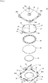
- Fig. 3 is an exploded perspective view of the piezoelectric pump 10 illustrated in Fig. 2 .
- Fig. 4 is a cross-sectional view of the piezoelectric pump 10 illustrated in Fig. 2 taken along line S-S in Fig. 2 .
- the piezoelectric pump 10 includes an outer housing 17, a top plate 37, a side plate 38, a vibrating plate 39, a piezoelectric element 40, and a cap 42 and has a structure whereby these members are stacked one on top of the other in this order in a top-bottom direction.
- the top plate 37, the side plate 38, and the vibrating plate 39 form a pump chamber 36.
- the piezoelectric pump 10 has dimensions (width x length x height) of 20 mm x 20 mm x 1.85 mm. Note that the height refers to the height of a portion of the piezoelectric pump 10 excluding a nozzle 18.
- the outer housing 17 includes the nozzle 18, and the discharge hole 24 through which air is to be discharged is formed in the center of the nozzle 18.
- the nozzle 18 has dimensions (outer diameter x inner diameter (i.e., diameter of the discharge hole 24) x height) of 2.0 mm x 0.8 mm x 1.6 mm. Threaded holes 56A to 56D are formed at four corners of the outer housing 17.
- the outer housing 17 is formed so as to have a U-shaped cross section while a lower portion thereof is open, and the top plate 37 of the pump chamber 36, the side plate 38 of the pump chamber 36, the vibrating plate 39, and the piezoelectric element 40 are accommodated in the outer housing 17.
- the outer housing 17 is formed from, for example, a resin.
- the top plate 37 of the pump chamber 36 has a circular plate-like shape and is formed from, for example, a metal.
- the top plate 37 includes a center portion 61, hook-shaped projecting portions 62, and an external terminal 63 that is to be connected to an external circuit.
- Each of the hook-shaped projecting portions 62 projects from the center portion 61 in the horizontal direction and is in contact with an inner wall of the outer housing 17.
- a ventilation hole 45 that causes the interior of the pump chamber 36 and the outside to communicate with each other is formed in the center portion 61 of the top plate 37.
- the ventilation hole 45 is formed at a position facing the discharge hole 24 of the outer housing 17.
- the top plate 37 is joined to a top surface of the side plate 38.
- the side plate 38 of the pump chamber 36 has a ring-like shape and is formed from, for example, a metal.
- the side plate 38 is joined to a top surface of the vibrating plate 39. Accordingly, the thickness of the side plate 38 corresponds to the height of the pump chamber 36.
- the vibrating plate 39 has a circular plate-like shape and is formed from, for example, a metal.
- the vibrating plate 39 forms a bottom surface of the pump chamber 36.
- the piezoelectric element 40 has a circular plate-like shape and is formed from, for example, a PZT-based ceramic.
- the piezoelectric element 40 is joined to a main surface of the vibrating plate 39, the main surface being located on the side opposite to the side on which the pump chamber 36 is present, and bends in response to an alternating-current (AC) voltage being applied to the piezoelectric element 40.
- the piezoelectric element 40 and the vibrating plate 39 form an actuator.
- a unified body formed of the top plate 37, the side plate 38, the vibrating plate 39, and the piezoelectric element 40 is elastically supported by the four projecting portions 62 of the top plate 37 with respect to the outer housing 17.
- An electrode-conduction plate 70 includes an inner terminal 73 that is to be connected to the piezoelectric element 40 and an outer terminal 72 that is to be connected to the external circuit. An end of the inner terminal 73 is soldered to a flat-plate surface of the piezoelectric element 40. By setting the position at which the end of the inner terminal 73 is soldered to a position corresponding to a node of bending vibration of the piezoelectric element 40, vibration of the inner terminal 73 can be further suppressed.
- a suction hole 53 having a circular plate-like shape is formed in the cap 42.
- the diameter of the suction hole 53 is larger than the diameter of the piezoelectric element 40.
- cutout portions 55A to 55D are formed at positions corresponding to the threaded holes 56A to 56D of the outer housing 17.
- the cap 42 includes projecting portions 52 that are formed at the outer peripheral edge of the cap 42 and that project toward the top plate 37.
- the cap 42 clamps the outer housing 17 by the projecting portions 52 and accommodates, together with the outer housing 17, the top plate 37 of the pump chamber 36, the side plate 38 of the pump chamber 36, the vibrating plate 39, and the piezoelectric element 40.
- the cap 42 is formed from, for example, a resin.
- a ventilation path 31 is formed between the unified body, which is formed of the top plate 37, the side plate 38, the vibrating plate 39, and the piezoelectric element 40, and the outer housing 17 and the cap 42.
- valve 101 The configuration of the valve 101 will now be described in detail with reference to Fig. 1 , Fig. 5 , and Fig. 6 .
- Fig. 5 and Fig. 6 are exploded perspective views of the valve 101 illustrated in Fig. 1 .
- Fig. 5 is an exploded perspective view of the valve 101 when viewed from the top surface side of the valve 101
- Fig. 6 is an exploded perspective view of the valve 101 when viewed from the bottom surface side of the valve 101.
- the valve 101 includes a second valve housing 192, a second seal member 152, a diaphragm 120, a first seal member 151, and a first valve housing 191 and has a structure whereby these members are stacked one on top of the other in this order.
- the first valve housing 191 includes the second ventilation hole 112, the third ventilation hole 113, a valve seat 139, a valve seat 145, a communication path 125, and a communication path 126.
- the second ventilation hole 112 is in communication with the suction hole 53 of the piezoelectric pump 10.
- the third ventilation hole 113 is in communication with the outside of the fluid control device 100.
- the valve seat 139 projects from the periphery of the third ventilation hole 113 toward the diaphragm 120.
- the valve seat 145 has a columnar shape and projects toward the diaphragm 120.
- the communication path 125 causes a first upper valve chamber 142 and a second upper valve chamber 133 to communicate with each other.
- the communication path 126 causes the first upper valve chamber 142 and a third upper valve chamber 134 to communicate with each other.
- the first valve housing 191 is formed from, for example, a resin.
- the valve seat 139 has a cylindrical shape, and the third ventilation hole 113 is formed in a center portion of the valve seat 139.
- the second valve housing 192 includes the first ventilation hole 111, a valve seat 138, a communication path 135, and a communication path 136.
- the first ventilation hole 111 is in communication with the connection hole 92 of the suction unit 9.
- the valve seat 138 has a columnar shape and projects toward the diaphragm 120.
- the communication path 135 causes a first lower valve chamber 141 and a second lower valve chamber 131 to communicate with each other.
- the communication path 136 causes the first lower valve chamber 141 and a third lower valve chamber 132 to communicate with each other.
- the second valve housing 192 is formed from, for example, a resin.
- a circular hole 121 is formed at the center of a region facing the valve seat 138.
- the diameter of the hole 121 is set to be smaller than the diameter of a surface of the valve seat 138, which is in contact with the diaphragm 120.
- a circular hole 122 is formed at the center of a region facing the valve seat 145 as illustrated in Fig. 1 , Fig. 5 , and Fig. 6 .
- the diameter of the hole 122 is set to be smaller than the diameter of a surface of the valve seat 145, which is in contact with the diaphragm 120.
- the diaphragm 120 is formed of a thin film having a rectangular shape.
- the material of the diaphragm 120 is, for example, a rubber such as ethylene propylene diene monomer (EPDM) rubber or a silicone rubber.
- the diaphragm 120 is clamped between the first valve housing 191 and the second valve housing 192 with the first seal member 151 interposed between the first valve housing 191 and the diaphragm 120 and with the second seal member 152 interposed between the second valve housing 192 and the diaphragm 120.
- Each of the first seal member 151 and the second seal member 152 is formed of a thin film having a rectangular shape.
- the material of each of the first seal member 151 and the second seal member 152 is, for example, a double-sided adhesive tape or an adhesive.
- an opening is formed in a region facing the first upper valve chamber 142, the communication path 125, the second upper valve chamber 133, the communication path 126, and the third upper valve chamber 134.
- an opening is formed in a region facing the first lower valve chamber 141, the communication path 135, the second lower valve chamber 131, the communication path 136, and the third lower valve chamber 132.
- the diaphragm 120 is fixed to the first valve housing 191 and the second valve housing 192 such that a portion of the diaphragm 120 around the periphery of the hole 121 is in contact with the valve seat 138, and that a portion of the diaphragm 120 around the periphery of the hole 122 is in contact with the valve seat 145.
- the valve seat 138 pressurizes the portion of the diaphragm 120 around the periphery of the hole 121.
- the valve seat 145 pressurizes the portion of the diaphragm 120 around the periphery of the hole 122.
- the diaphragm 120 divides a region enclosed by the first valve housing 191 and the second valve housing 192 as a result of being fixed to the first valve housing 191 and the second valve housing 192.
- the diaphragm 120 forms the first lower valve chamber 141 having a columnar shape, the second lower valve chamber 131 having a ring-like shape, the third lower valve chamber 132 having a columnar shape, the first upper valve chamber 142 having a ring-like shape, the second upper valve chamber 133 having a columnar shape, and the third upper valve chamber 134 having a ring-like shape.
- the first lower valve chamber 141 is in communication with the first ventilation hole 111.
- the second lower valve chamber 131 is in communication with the first lower valve chamber 141 via the communication path 135.
- the third lower valve chamber 132 is in communication with the first lower valve chamber 141 via the communication path 136.
- the second upper valve chamber 133 is in communication with the first upper valve chamber 142 via the communication path 125 and is in communication with the second ventilation hole 112.
- the third upper valve chamber 134 is in communication with the first upper valve chamber 142 via the communication path 126.
- first lower valve chamber 141, the communication path 135, the second lower valve chamber 131, the communication path 136, and the third lower valve chamber 132 correspond to a first region according to the present invention.
- the first upper valve chamber 142, the communication path 125, the second upper valve chamber 133, the communication path 126, and the third upper valve chamber 134 correspond to a second region according to the present invention.
- the valve seat 145 corresponds to a first valve seat according to the present invention.
- the valve seat 139 corresponds to a second valve seat according to the present invention.
- the valve seat 138 corresponds to a third valve seat according to the present invention.
- the hole 122 corresponds to a first hole according to the present invention.
- the hole 121 corresponds to a second hole according to the present invention.
- the diaphragm 120 forms, together with the first valve housing 191 and the second valve housing 192, a check valve 140.
- the check valve 140 is formed of the first lower valve chamber 141, the first upper valve chamber 142, the valve seat 145, a portion of the diaphragm 120 facing the first lower valve chamber 141, and a portion of the diaphragm 120 facing the first upper valve chamber 142.
- the diaphragm 120 forms, together with the first valve housing 191 and the second valve housing 192, a check valve 160.
- the check valve 160 is formed of the second lower valve chamber 131, the second upper valve chamber 133, the valve seat 138, a portion of the diaphragm 120 facing the second lower valve chamber 131, and a portion of the diaphragm 120 facing the second upper valve chamber 133.
- the diaphragm 120 forms, together with the first valve housing 191 and the second valve housing 192, an exhaust valve 170.
- the exhaust valve 170 is formed of the third lower valve chamber 132, the third upper valve chamber 134, the valve seat 139, a portion of the diaphragm 120 facing the third lower valve chamber 132, and a portion of the diaphragm 120 facing the third upper valve chamber 134.
- the check valve 140 In the check valve 140, the diaphragm 120 moves into and out of contact with the valve seat 145 due to a pressure difference between the first lower valve chamber 141 and the first upper valve chamber 142. As a result, the check valve 140 enables the flow of the air from the first upper valve chamber 142 toward the first lower valve chamber 141 and interrupts the flow of the air from the first lower valve chamber 141 toward the first upper valve chamber 142.
- the check valve 160 In the check valve 160, the diaphragm 120 moves into and out of contact with the valve seat 138 due to a pressure difference between the second lower valve chamber 131 and the second upper valve chamber 133. As a result, the check valve 160 enables the flow of the air from the second lower valve chamber 131 toward the second upper valve chamber 133 and interrupts the flow of the air from the second upper valve chamber 133 toward the second lower valve chamber 131.
- the diaphragm 120 moves into contact with the valve seat 139 in the exhaust valve 170. Conversely, in the case where a relationship of S1 x (P1 - P2) ⁇ S3 x (P3 - P1) is satisfied, the diaphragm 120 moves out of contact with the valve seat 139. In other words, the diaphragm 120 moves into and out of contact with the valve seat 139 synchronously with switching of the piezoelectric pump 10 on and off. As a result, the pressure in the container 90 of the suction unit 9 automatically changes synchronously with switching of the piezoelectric pump 10 on and off.
- each of the valve chambers 131, 132, 133, 134, 141, and 142 is a circular shape, and thus, tension is applied uniformly to the diaphragm 120 (particularly the portions of the diaphragm 120 around the periphery of the holes 121 and 122).
- the probability of the diaphragm 120 being in contact with the valve seat 138 in a state where the hole 121 of the diaphragm 120 is inclined with respect to the valve seat 138 and the probability of the hole 121 of the diaphragm 120 being displaced with respect to the valve seat 138 in the horizontal direction are reduced.
- the probability of the diaphragm 120 being in contact with the valve seat 145 in a state where the hole 122 of the diaphragm 120 is inclined with respect to the valve seat 145 and the probability of the hole 122 of the diaphragm 120 being displaced with respect to the valve seat 145 in the horizontal direction are reduced. Therefore, according to the valve 101, opening and closing of each of the valves can be performed with higher certainty.
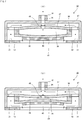
- Figs. 7(A) and 7(B) are cross-sectional views of the piezoelectric pump 10 illustrated in Fig. 1 taken along line S-S when the piezoelectric pump 10 is caused to operate at a first mode frequency (fundamental wave).
- arrows in Figs. 7(A) and 7(B) indicate the flow of air.
- the air discharged from the pump chamber 36 is discharged through the discharge hole 24 while the air outside the piezoelectric pump 10 is drawn in via the suction hole 53 and the ventilation path 31.
- the flow rate of the air that is discharged through the discharge hole 24 is increased by the flow rate of the air that is drawn in.
- Fig. 8 is a diagram illustrating the flow of the air in the fluid control device 100 during the period when the piezoelectric pump 10 is driven. Arrows in Fig. 8 indicate the flow of the air. In Fig. 8 , the piezoelectric pump 10 and the suction unit 9 are not illustrated.
- the first lower valve chamber 141, the communication path 135, the second lower valve chamber 131, the communication path 136, and the third lower valve chamber 132 correspond to the first region according to the present invention.
- the first upper valve chamber 142, the communication path 125, the second upper valve chamber 133, the communication path 126, and the third upper valve chamber 134 correspond to the second region according to the present invention.
- the valve seat 145 corresponds to the first valve seat according to the present invention.
- the valve seat 139 corresponds to the second valve seat according to the present invention.
- the valve seat 138 corresponds to the third valve seat according to the present invention.
- the hole 122 corresponds to the first hole according to the present invention.
- the hole 121 corresponds to the second hole according to the present invention.
- a user places the suction port 91 of the suction unit 9 onto, for example, a human breast or an animal breast.
- the pressure in the container 90 before the piezoelectric pump 10 is driven is at atmospheric pressure.
- the fluid control device 100 switches the piezoelectric pump 10 on when suction of a liquid using the suction unit 9 is started.
- the air in the second upper valve chamber 133 is drawn into the piezoelectric pump 10 via the second ventilation hole 112 and the suction hole 53. Then, the air in the piezoelectric pump 10 is discharged through the discharge hole 24.
- the pressure in the second lower valve chamber 131 is higher than the pressure in the second upper valve chamber 133.
- the portion of the diaphragm 120 around the periphery of the hole 121 moves out of contact with the valve seat 138, and the first ventilation hole 111 and the second ventilation hole 112 are caused to communicate with each other via the hole 121.
- the pressure in the first lower valve chamber 141 is higher than the pressure in the first upper valve chamber 142.
- the portion of the diaphragm 120 around the periphery of the hole 122 is maintained in contact with the valve seat 145 and interrupts the communication between the first lower valve chamber 141 and the first upper valve chamber 142.
- the pressure in the third lower valve chamber 132 is higher than the pressure in the third upper valve chamber 134.
- the diaphragm 120 seals the third ventilation hole 113 and interrupts the communication between the second ventilation hole 112 and the third ventilation hole 113.
- the first ventilation hole 111 and the second ventilation hole 112 are caused to communicate with each other, and the communication between the first ventilation hole 111 and the third ventilation hole 113 and the communication between the second ventilation hole 112 and the third ventilation hole 113 are interrupted.
- the air in the container 90 of the suction unit 9 is discharged from the connection hole 92 toward the first lower valve chamber 141 of the valve 101 via the first ventilation hole 111. Consequently, the pressure (air pressure) in the container 90 is reduced to be lower than atmospheric pressure and becomes a negative pressure.
- the suction unit 9 can suck a liquid (e.g., breast milk or the like) outside the container 90 into the container 90 through the suction port 91.
- the suction unit 9 stores the liquid in the container 90 and discharges the air in the container 90 through the connection hole 92.
- the air discharged to the first lower valve chamber 141 flows into the second upper valve chamber 133 via the communication path 135, the second lower valve chamber 131, and the hole 121. Then, the air in the second upper valve chamber 133 is drawn into the piezoelectric pump 10 via the second ventilation hole 112 and the suction hole 53 and is discharged through the discharge hole 24.
- Fig. 9 is a diagram illustrating the flow of the air in the fluid control device 100 immediately after driving of the piezoelectric pump 10 has been discontinued. Arrows in Fig. 9 indicate the flow of the air. In Fig. 9 , the piezoelectric pump 10 and the suction unit 9 are not illustrated.
- the fluid control device 100 switches the piezoelectric pump 10 off and discontinues driving of the piezoelectric pump 10. In this case, since the pressure in the second region is lower than atmospheric pressure, a small portion of the air flows into the piezoelectric pump 10 through the discharge hole 24 of the piezoelectric pump 10 and flows into the second region via the suction hole 53 and the second ventilation hole 112.
- the pressure in the second lower valve chamber 131 is reduced to be lower than the pressure of the second upper valve chamber 133. Consequently, the diaphragm 120 closes the hole 121 by coming into contact with the valve seat 138.
- the pressure in the first lower valve chamber 141 is reduced to be lower than the pressure in the first upper valve chamber 142. Consequently, the portion of the diaphragm 120 around the periphery of the hole 122 moves out of contact with the valve seat 145 and causes the first ventilation hole 111 and the second region to communicate with each other.
- the pressure of the third lower valve chamber 132 is reduced to be lower than the pressure in the third upper valve chamber 134. Consequently, the diaphragm 120 opens the third ventilation hole 113 by moving out of contact with the valve seat 139.
- the first ventilation hole 111 and the third ventilation hole 113 communicate with each other.
- the air rapidly flows through the third ventilation hole 113 into the container 90 via the third upper valve chamber 134, the communication path 126, the first upper valve chamber 142, the hole 122, the first lower valve chamber 141, and the first ventilation hole 111 (see Fig. 9 ).
- the suction port 91 of the suction unit 9 can be easily removed from a human breast or an animal breast.
- valve 101 of the present embodiment after making the pressure in the container 90 become a negative pressure by drawing in the air from the container 90, the pressure in the container 90 can be rapidly restored to atmospheric pressure by causing the air to flow into the container 90.
- advantageous effects similar to the above can be obtained by the fluid control device 100 that includes the valve 101 according to the present embodiment.
- a fluid control device 200 according to a second embodiment of the present invention will be described below.
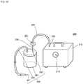
- Fig. 10 is a diagram illustrating the appearance of the fluid control device 200 according to the second embodiment of the present invention.
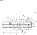
- Fig. 11 is a cross-sectional view of a valve 201 illustrated in Fig. 10 .
- the fluid control device 200 is a device that sucks in a liquid (e.g., sputum or the like).
- the fluid control device 200 includes a pump 210, a suction unit 209, and the valve 201.
- the pump 210 includes a suction hole 253 that is used for drawing in air, a discharge hole (not illustrated) that is used for discharging the air, and a pressure gauge 215 that shows an air-drawing pressure.
- the suction unit 209 includes a container 290, a connection hole 292, and a tube 294.
- a suction port 291 which is an end portion of the tube 294, is inserted into, for example, a human oral cavity or an animal oral cavity.
- a liquid e.g., sputum or the like
- sputum or the like
- connection hole 292 corresponds to an example of a connecting portion according to the present invention.
- valve 201 includes a filter 250 in a second housing 293.
- second valve housing 293 of the valve 201 and the second housing 192 of the valve 101 is that a space in which the filter 250 is disposed is formed in the second housing 293.
- the rest of the configuration of the valve 201 is the same as that of the valve 101.
- the filter 250 allows a gas to pass therethrough and hinders a liquid from passing therethrough. In order to prevent infection and contamination, the filter 250 sucks in, for example, a bacterium.
- the filter 250 is bonded to the inner wall of the second housing 293 with an adhesive or the like.
- the suction port 291 is connected to the container 290 via the tube 294.
- the first ventilation hole 111 of the valve 201 is connected to the connection hole 292 of the suction unit 209 via a tube 295.
- the second ventilation hole 112 of the valve 201 is connected to the suction hole 253 of the pump 210 via a tube 296.
- the third ventilation hole 113 of the valve 201 is released under atmospheric pressure.
- the first lower valve chamber 141, the communication path 135, the second lower valve chamber 131, the communication path 136, and the third lower valve chamber 132 correspond to the first region according to the present invention.
- the first upper valve chamber 142, the communication path 125, the second upper valve chamber 133, the communication path 126, and the third upper valve chamber 134 correspond to the second region according to the present invention.
- the valve seat 145 corresponds to the first valve seat according to the present invention.
- the valve seat 139 corresponds to the second valve seat according to the present invention.
- the valve seat 138 corresponds to the third valve seat according to the present invention.
- the hole 122 corresponds to the first hole according to the present invention.
- the hole 121 corresponds to the second hole according to the present invention.
- the flow of the air in the fluid control device 200 during the period when the pump 210 is driven is substantially the same as the flow of the air in the fluid control device 100 illustrated in Fig. 8 .
- the air flows by passing through the filter 250.
- the flow of the air in the fluid control device 200 when driving of the pump 210 is discontinued, when the pressure in the container 290 reaches a maximum drawing pressure of the pump 210, or when a flow path is blocked is also substantially the same as the flow of the air in the fluid control device 100 illustrated in Fig. 9 .
- the air flows by passing through the filter 250.
- the suction port 291 is blocked if human body tissue is sucked in through the suction port 291 in a state where there is no target to be sucked in.
- the pressure in the first region becomes equal to or lower than the pressure in the second region.
- the diaphragm 120 automatically opens the third ventilation hole 113 and the hole 122, and the suction port 291 is released under atmospheric pressure.
- the valve 201 can obtain advantageous effects similar to those of the valve 101.
- the valve 201 can cause the pressure in the container 290 to become a negative pressure by drawing in the air from the container 290 and then can rapidly restore the pressure in the container 290 to atmospheric pressure by causing the air to flow into the container 290.
- advantageous effects similar to the above can be obtained by the fluid control device 200 that includes the valve 201.
- the filter 250 becomes clogged, and the flow path resistance (air-flow resistance) of the filter 250 increases. In other words, the fluid control device 200 cannot properly draw in the air.
- a common suction device of the related art also includes a filter
- the suction device cannot detect a situation in which the filter has become clogged.
- a filter in a suction device of the related art is replaced by a nurse or the like who checks the appearance of the filter or manages the length of time the filter is used.
- it is difficult to perform quantitative management of a filter.
- noise that is generated when the third ventilation hole 113 and the hole 122 are opened under atmospheric pressure enables a nurse or the like to easily detect a situation in which the filter 250 has become clogged.
- a fluid control device 300 according to a third embodiment of the present invention will be described below.
- Fig. 12 is a sectional view of the fluid control device 300 according to the third embodiment of the present invention. Arrows in Fig. 12 indicate the flow of a fluid.
- the fluid control device 300 is a drainage that sucks in a liquid (e.g., pleural effusion, blood, or the like).
- the fluid control device 300 includes a pump 310, a suction unit 309, and the valve 101.
- the pump 310 may be any pump and has a suction hole (not illustrated) used for drawing in air and a discharge hole (not illustrated) used for discharging the air.
- the suction unit 309 is a so-called chest drain bag.
- the suction unit 309 includes a first container 390A, a second container 390B, a third container 390C, a tube 330, a connection hole 392, and the tube 337.
- a suction port 391, which is an end portion of the tube 337, is inserted into the chest cavity of a patient 308.
- the patient 308 is, for example, a human or an animal.
- connection hole 392 corresponds to an example of the connecting portion according to the present invention.
- the first container 390A is a so-called drainage bottle.
- the first container 390A is connected to the suction port 391.
- a liquid B e.g., pleural effusion, blood, or the like
- a liquid B e.g., pleural effusion, blood, or the like
- the second container 390B is a so-called water-sealed bottle.
- the second container 390B is connected to the first container 390A.
- Water W1 is stored in the second container 390B.
- the second container 390B allows the air to pass therethrough and hinders the liquid B from passing therethrough.
- the third container 390C is a so-called drawing-pressure control bottle.
- the third container 390C is connected to the second container 390B and the suction hole of the pump 310.
- Water W2 is stored in the third container 390C.
- a pipe 336 is inserted into the third container 390C, and an end portion of the pipe 336 is immersed in the water W2.
- the third container 390C adjusts the drawing pressure at which the pump 310 draws in the air in accordance with the water level of the water W2 and the air that flows into the pipe 336 from the end portion of the pipe 336.
- the valve 101 is mounted on a top surface of the third container 390C so as to block the connection hole 392, which is an exit of the third container 390C.
- the suction port 391 is connected to the container 390A via the tube 330.
- the first ventilation hole 111 of the valve 101 is connected to the connection hole 392 of the suction unit 309.
- the second ventilation hole 112 of the valve 101 is connected to the suction hole of the pump 310 via a tube 337.
- the third ventilation hole 113 of the valve 101 is opened under atmospheric pressure.
- the flow of the air in the fluid control device 300 during the period when the pump 310 is driven is the same as the flow of the air in the fluid control device 100 illustrated in Fig. 8 .
- the flow of the air in the fluid control device 300 when driving of the pump 310 is discontinued, when the pressure in the container 390A reaches a maximum drawing pressure of the pump 310, or when a flow path is blocked is also the same as the flow of the air in the fluid control device 100 illustrated in Fig. 9 .
- the suction port 391 is blocked if human body tissue is sucked in through the suction port 391 in a state where there is no target to be sucked in.
- the pressure in the first region becomes equal to or lower than the pressure in the second region.
- the diaphragm 120 automatically opens the third ventilation hole 113 and the hole 122, and the suction port 391 is released under atmospheric pressure.
- the valve 101 can cause the pressure in the third container 390C to become a negative pressure by drawing in the air from the third container 390C and then can rapidly restore the pressure in the third container 390C to atmospheric pressure by causing the air to flow into the third container 390C.
- valve 101 which automatically opens the suction port 391, may preferably be used in treatment for pneumothorax.
- valve 101 since the structure of the valve 101 is simple and inexpensive, the suction unit 309 and the valve 101 can be used as disposable members. Therefore, the valve 101 can reduce the costs for maintenance of a hospital.
- a fluid control device 400 according to a fourth embodiment of the present invention will be described below.
- Fig. 13 is a sectional view of the fluid control device 400 according to the fourth embodiment of the present invention.
- the difference between the fluid control device 400 and the fluid control device 100 is a valve 401.
- the difference between the valve 401 and the valve 101 is that the valve 401 has a fourth ventilation hole 114.
- the diameter of the fourth ventilation hole 114 is smaller than the diameter of the first ventilation hole 111.
- the diameter of the fourth ventilation hole 114 is smaller than the diameter of the second ventilation hole 112. Note that the rest of the configuration of the fluid control device 400 is the same as that of the fluid control device 100, and thus, the description thereof will be omitted.
- the flow of air in the fluid control device 400 is classified into a first stage, a second stage, and a third stage.
- the first stage corresponds to the period from when driving of the piezoelectric pump 10 is started until the pressure in the container 90 reaches a maximum drawing pressure of the piezoelectric pump 10.
- the second stage corresponds to the period from when the pressure in the container 90 reaches the maximum drawing pressure of the piezoelectric pump 10 until driving of the piezoelectric pump 10 is discontinued.
- the third stage corresponds to the time immediately after driving of the piezoelectric pump 10 has been discontinued.
- Fig. 14 is a diagram illustrating the flow of the air in the fluid control device 400 during the period from when driving of the piezoelectric pump 10 is started until the pressure in the container 90 reaches the maximum drawing pressure. Arrows in Fig. 14 indicate the flow of the air. In Fig. 14 , the piezoelectric pump 10 and the suction unit 9 are not illustrated.
- a user places the suction port 91 of the suction unit 9 onto, for example, a human breast or an animal breast.
- the pressure in the container 90 before the piezoelectric pump 10 is driven is at atmospheric pressure.
- the fluid control device 400 switches the piezoelectric pump 10 on when suction of a liquid using the suction unit 9 is started.
- the air in the second upper valve chamber 133 is drawn into the piezoelectric pump 10 via the second ventilation hole 112 and the suction hole 53. Then, the air in the piezoelectric pump 10 is discharged through the discharge hole 24.
- the pressure in the first lower valve chamber 141 is higher than the pressure in the first upper valve chamber 142.
- the portion of the diaphragm 120 around the periphery of the hole 122 is maintained in contact with the valve seat 145 and interrupts the communication between the first lower valve chamber 141 and the first upper valve chamber 142.
- the pressure in the second lower valve chamber 131 is higher than the pressure in the second upper valve chamber 133.
- the portion of the diaphragm 120 around the periphery of the hole 121 moves out of contact with the valve seat 138, and the first ventilation hole 111 and the second ventilation hole 112 are caused to communicate with each other via the hole 121.
- the pressure in the third lower valve chamber 132 is higher than the pressure in the third upper valve chamber 134.
- the diaphragm 120 seals the third ventilation hole 113 and interrupts the communication between the second ventilation hole 112 and the third ventilation hole 113.
- the first ventilation hole 111 and the second ventilation hole 112 are caused to communicate with each other, and the communication between the first ventilation hole 111 and the third ventilation hole 113 and the communication between the second ventilation hole 112 and the third ventilation hole 113 are interrupted.
- the air in the container 90 of the suction unit 9 is discharged from the connection hole 92 toward the first lower valve chamber 141 of the valve 401 via the first ventilation hole 111. Consequently, the pressure (air pressure) in the container 90 is reduced to be lower than atmospheric pressure and becomes a negative pressure.
- the suction unit 9 can suck a liquid (e.g., breast milk or the like) outside the container 90 into the container 90 through the suction port 91.
- the suction unit 9 stores the liquid in the container 90 and discharges the air in the container 90 through the connection hole 92.
- the air discharged to the first lower valve chamber 141 flows into the second upper valve chamber 133 via the communication path 135, the second lower valve chamber 131, and the hole 121. Then, the air in the second upper valve chamber 133 is drawn into the piezoelectric pump 10 via the second ventilation hole 112 and the suction hole 53 and is discharged through the discharge hole 24.
- the fluid control device 400 a small portion of the air outside the valve 401 is drawn into the valve 401 via the fourth ventilation hole 114.
- the flow rate of the air that is drawn in from the container 90 is smaller than that in the fluid control device 100.
- Fig. 15 is a diagram illustrating the flow of the air in the fluid control device 400 during the period from when the pressure in the container 90 reaches the maximum drawing pressure until driving of the piezoelectric pump 10 is discontinued. Arrows in Fig. 15 indicate the flow of the air. In Fig. 15 , the piezoelectric pump 10 and the suction unit 9 are not illustrated.
- the piezoelectric pump 10 cannot draw in the air from the container 90.
- the air is drawn in through the fourth ventilation hole 114 and flows into the piezoelectric pump 10 by passing the hole 121 of the check valve 160. Consequently, in the exhaust valve 170, a relationship of P2 ⁇ P1 and the relationship of S1 ⁇ (P1 - P2) > S3 x (P3 - P1) are satisfied.
- the fluid control device 400 maintains a state where the third ventilation hole 113 is closed.
- the fluid control device 400 can maintain a decompressed state of the container 90 during the period when the piezoelectric pump 10 is kept driven.
- Fig. 16 is a diagram illustrating the flow of the air in the fluid control device 400 immediately after driving of the piezoelectric pump 10 has been discontinued. Arrows in Fig. 16 indicate the flow of the air. In Fig. 16 , the piezoelectric pump 10 and the suction unit 9 are not illustrated.
- the fluid control device 400 switches the piezoelectric pump 10 off and discontinues driving of the piezoelectric pump 10. In this case, since the pressure in the valve 401 is lower than atmospheric pressure. Thus, a small portion of the air outside the valve 401 is drawn into the valve 401 through the fourth ventilation hole 114.
- the diameter of the fourth ventilation hole 114 is very small compared with the diameter of the second ventilation hole 112, the influence of the fourth ventilation hole 114 is small. Consequently, a small portion of the air flows into the piezoelectric pump 10 mainly through the discharge hole 24 of the piezoelectric pump 10 and flows into the second region via the suction hole 53 and the second ventilation hole 112.
- the pressure in the second lower valve chamber 131 is reduced to be lower than the pressure in the second upper valve chamber 133.
- the diaphragm 120 closes the hole 121 by coming into contact with the valve seat 138.
- the pressure in the first lower valve chamber 141 is reduced to be lower than the pressure in the first upper valve chamber 142. Consequently, the portion of the diaphragm 120 around the periphery of the hole 122 moves out of contact with the valve seat 145 and causes the first ventilation hole 111 and the second region to communicate with each other.
- the pressure of the third lower valve chamber 132 is reduced to be lower than the pressure in the third upper valve chamber 134.
- a relationship of pressure P2 ⁇ P1 and a relationship of S1 x (P1 - P2) ⁇ S3 x (P3 - P1) are satisfied. Accordingly, the diaphragm 120 opens the third ventilation hole 113 by moving out of contact with the valve seat 139.
- the first ventilation hole 111 and the third ventilation hole 113 are caused to communicate with each other.
- the air rapidly flows through the third ventilation hole 113 into the container 90 via the third upper valve chamber 134, the communication path 126, the first upper valve chamber 142, the hole 122, the first lower valve chamber 141, and the first ventilation hole 111 (see Fig. 9 ).
- the suction port 91 of the suction unit 9 can be easily removed from a human breast or an animal breast.
- the valve 401 can cause the pressure in the container 90 to become a negative pressure by drawing in the air from the container 90 and then can rapidly restore the pressure in the container 90 to atmospheric pressure by causing the air to flow into the container 90.
- advantageous effects similar to the above can be obtained by the fluid control device 400 that includes the valve 401 according to the present embodiment.
- the air is used as a gas in the above-described embodiments, the gas is not limited to the air, and the present invention can be applied to a case where the gas is a gas other than the air.
- a target to be sucked in may be a material (e.g., a gel-like material) other than a liquid.
- the piezoelectric pump 10 includes a unimorph-type actuator that performs bending vibration
- the piezoelectric pump 10 may include a bimorph-type actuator in which a piezoelectric element is attached to each of the two surfaces of a vibrating plate and which performs bending vibration.
- the piezoelectric pump 10 includes an actuator that performs bending vibration by expansion and contraction of the piezoelectric element 40, the piezoelectric pump 10 is not limited to having this configuration.
- the piezoelectric pump 10 may include an actuator that performs bending vibration as a result of being electromagnetically driven.
- the piezoelectric element 40 is formed from a PZT-based ceramic in the above-described embodiments, the material of the piezoelectric element 40 is not limited to this.
- the piezoelectric element 40 may be formed from a piezoelectric material of a non-lead-based piezoelectric ceramic, such as a potassium-sodium niobate-based ceramic or an alkali niobate-based ceramic, or the like.
Landscapes
- Health & Medical Sciences (AREA)
- Heart & Thoracic Surgery (AREA)
- Engineering & Computer Science (AREA)
- Life Sciences & Earth Sciences (AREA)
- Veterinary Medicine (AREA)
- Public Health (AREA)
- General Health & Medical Sciences (AREA)
- Animal Behavior & Ethology (AREA)
- Anesthesiology (AREA)
- Biomedical Technology (AREA)
- Hematology (AREA)
- Vascular Medicine (AREA)
- General Engineering & Computer Science (AREA)
- Pediatric Medicine (AREA)
- Fluid Mechanics (AREA)
- Physics & Mathematics (AREA)
- Mechanical Engineering (AREA)
- Otolaryngology (AREA)
- Nursing (AREA)
- Reciprocating Pumps (AREA)
- Valve Housings (AREA)
- Fluid-Pressure Circuits (AREA)
- External Artificial Organs (AREA)
Abstract
Description
- The present invention relates to a valve that switches the flow of a gas and a fluid control device that includes the valve.
- In the related art, various fluid control devices that control the flow of a gas by using a valve have been designed. For example,
Patent Document 1 discloses a fluid control device that includes a pump and a valve. - The pump has an air-suction hole and an air-discharge hole.
- The valve includes a diaphragm, a first valve housing, and a second valve housing and has a structure whereby the diaphragm, the first valve housing, and the second valve housing are stacked one on top of the other in this order. In addition, the valve has a ventilation hole, an exhaust port, and a cuff-connection port. The discharge hole of the pump is connected to the ventilation hole. The exhaust port is opened under atmospheric pressure. The fluid control device is connected to a cuff as a result of a manchette rubber tube of the cuff being connected to the cuff-connection port of the valve.
- With the above-described configuration, the fluid control device of
Patent Document 1 drives the pump and discharges air into the valve through the discharge hole of the pump. The air discharged to the valve flows into the cuff through the cuff-connection port. - In this manner, the fluid control device of
Patent Document 1 fills the cuff (container) with compressed air. Then, the fluid control device ofPatent Document 1 discontinues driving of the pump and causes the compressed air in the cuff (container) to be exhausted through the exhaust port. - Patent Document 1: International Publication No.
2012/141113 Pamphlet - However, the fluid control device of
Patent Document 1 is not a device that causes the pressure in a container to become a negative pressure by drawing in a gas from the container. Thus, the fluid control device ofPatent Document 1 is not suitable for applications, such as causing the pressure in a container to become a negative pressure by drawing in a gas from the container. - It is an object of the present invention to provide a valve capable of causing the pressure in a container to become a negative pressure by drawing in a gas from the container and then restoring the pressure in the container to atmospheric pressure by causing the gas to flow into the container, and to provide a fluid control device that includes the valve.
- A valve according to the present invention has the following configuration in order to solve the above-mentioned problem.
- (1) The valve according to the present invention includes a valve housing in which a first ventilation hole, a second ventilation hole, and a third ventilation hole are formed and a diaphragm that divides a region in the valve housing into a first region and a second region. The diaphragm is fixed to the valve housing such that the diaphragm causes the first ventilation hole and the second ventilation hole to communicate with each other and interrupts communication between the first ventilation hole and the third ventilation hole and communication between the second ventilation hole and the third ventilation hole when a pressure in the first region, which is in communication with the first ventilation hole in the valve housing, is higher than a pressure in the second region, which is in communication with the second ventilation hole in the valve housing, and such that the diaphragm causes the first ventilation hole and the third ventilation hole to communicate with each other when the pressure in the first region is lower than the pressure in the second region.
In this configuration, for example, a suction unit having a suction port is connected to the first ventilation hole. A suction hole of a pump is connected to the second ventilation hole. The third ventilation hole is opened under atmospheric pressure. In this case, when the pump is driven, the air in the second region is drawn into the pump via the second ventilation hole and the suction hole. Then, the air in the pump is discharged through a discharge hole. As a result, in the valve, the pressure in the first region becomes higher than the pressure in the second region.
In the valve, which has the above configuration, in the case where the pressure in the first region is higher than the pressure in the second region, the first ventilation hole and the second ventilation hole are caused to communicate with each other, and the communication between the first ventilation hole and the third ventilation hole and the communication between the second ventilation hole and the third ventilation hole are interrupted.
As a result, a gas in a container of the suction unit is discharged to the first region of the valve via the first ventilation hole and is drawn into the pump via the second ventilation hole and the suction hole. Consequently, the pressure (gas pressure) in the container is reduced from atmospheric pressure and becomes a negative pressure. Thus, the suction unit can suck a liquid (e.g., breast milk, blood, pleural effusion, sputum, or the like) outside the container into the container through the suction port.
Next, when driving of the pump is discontinued, the pressure in the second region is lower than atmospheric pressure, and thus, a small portion of the gas flows into the pump through the discharge hole of the pump and flows into the second region via the suction hole and the second ventilation hole. As a result, in the valve, the pressure in the first region is reduced to be lower than the pressure in the second region.
In the valve, which has the above configuration, in the case where the pressure in the first region is lower than the pressure in the second region, the first ventilation hole and the third ventilation hole are caused to communicate with each other. Then, the gas flows in through the third ventilation hole, flows out from the first ventilation hole, and flows into the container. This causes an increase in the pressure (gas pressure) in the container and restores the pressure in the container to atmospheric pressure. Accordingly, the suction port of the suction unit can be easily removed from a human breast or an animal breast.
Therefore, according to the configuration, after making the pressure in the container become a negative pressure by drawing in the gas from the container, the pressure in the container can be restored to atmospheric pressure by causing the gas to flow into the container. - (2) It is preferable that the diaphragm move into and out of contact with a portion of the valve housing due to a pressure difference between the first region and the second region and perform switching of a communication state between the first ventilation hole and the third ventilation hole.
In the above configuration, in the case where the pressure in the first region is higher than the pressure in the second region, the diaphragm comes into contact with the portion of the valve housing and interrupts the communication between the first ventilation hole and the third ventilation hole and the communication between the second ventilation hole and the third ventilation hole.
In contrast, in the case where the pressure in the first region is lower than the pressure in the second region, the diaphragm moves out of contact with the portion of the valve housing and causes the first ventilation hole and the third ventilation hole to communicate with each other. - (3) It is preferable that a first valve seat projecting toward the diaphragm in the second region be formed on the portion of the valve housing. In addition, it is preferable that a first hole be formed in the diaphragm and that the diaphragm be fixed to the valve housing such that a portion of the diaphragm around a periphery of the first hole is in contact with the first valve seat.
In the above configuration, in the case where the pressure in the first region is higher than the pressure in the second region, the diaphragm comes into contact with the first valve seat and interrupts the communication between the first ventilation hole and the third ventilation hole and the communication between the second ventilation hole and the third ventilation hole.
In contrast, in the case where the pressure in the first region is lower than the pressure in the second region, the diaphragm moves out of contact with the first valve seat and causes the first ventilation hole and the second ventilation hole to communicate with each other. - (4) It is preferable that a second valve seat projecting toward the diaphragm in the second region be formed on the portion of the valve housing. In addition, it is preferable that a third hole be formed in the second valve seat and that the diaphragm be fixed to the valve housing such that the diaphragm is in contact with the second valve seat.
In the above configuration, in the case where the pressure in the first region is higher than the pressure in the second region, the diaphragm comes into contact with the second valve seat and interrupts the communication between the first ventilation hole and the third ventilation hole and the communication between the second ventilation hole and the third ventilation hole.
In contrast, in the case where the pressure in the first region is lower than the pressure in the second region, the diaphragm moves out of contact with the second valve seat and causes the third ventilation hole and the second ventilation hole to communicate with each other. - (5) It is preferable that a third valve seat projecting toward the diaphragm in the first region be formed on the valve housing. In addition, it is preferable that a second hole be formed in the diaphragm and that the diaphragm be fixed to the valve housing such that a portion of the diaphragm around a periphery of the second hole is in contact with the third valve seat.
In the above configuration, in the case where the pressure in the first region is higher than the pressure in the second region, the diaphragm moves out of contact with the third valve seat and causes the first ventilation hole and the second ventilation hole to communicate with each other.
In contrast, in the case where the pressure in the first region is lower than the pressure in the second region, the diaphragm comes into contact with the third valve seat. - (6) A fourth ventilation hole that is in communication with the first region is formed in the valve housing.
A fluid control device according to the present invention has the following configuration in order to solve the above-mentioned problem. - (7) The fluid control device according to the present invention includes a pump that has a suction hole for a gas and a discharge hole for the gas, a suction unit that has a suction port through which a fluid is to be sucked in and a connecting portion, and the valve described in any one of the above (1) to (6). The first ventilation hole is connected to the connecting portion of the suction unit, and the second ventilation hole is connected to the suction hole of the pump.
With the above configuration, by using the valve described in any one of the above (1) to (6), advantageous effects similar to the above can be obtained by the fluid control device that includes the valve. - (8) It is preferable that the suction unit include a first container that is connected to the suction port and in which a fluid sucked in through the suction port is to be stored, a second container that is connected to the first container and that allows the gas to pass through the second container and hinders the fluid from passing through the second container, and a third container that is connected to the second container and the suction hole of the pump and that adjusts a drawing pressure at which the pump draws in the gas.
- With the above configuration, the fluid control device is used as a drainage. Blood, pleural effusion, or the like that has sucked in through the suction port is stored in the first container.
- According to the present invention, the pressure in a container can be caused to become a negative pressure by drawing in a gas from the container, and then the pressure in the container can be restored to atmospheric pressure by causing the gas to flow into the container.
-
- [
Fig. 1] Fig. 1 is a sectional view of a principal portion of afluid control device 100 according to a first embodiment of the present invention. - [
Fig. 2] Fig. 2 is an external perspective view of apiezoelectric pump 10 illustrated inFig. 1 . - [
Fig. 3] Fig. 3 is an exploded perspective view of thepiezoelectric pump 10 illustrated inFig. 2 . - [
Fig. 4] Fig. 4 is a cross-sectional view of thepiezoelectric pump 10 illustrated inFig. 2 taken along line S-S inFig. 2 . - [
Fig. 5] Fig. 5 is an exploded perspective view of avalve 101 illustrated inFig. 1 . - [
Fig. 6] Fig. 6 is an exploded perspective view of thevalve 101 illustrated inFig. 1 . - [
Fig. 7] Figs. 7(A) and 7(B) are cross-sectional views of thepiezoelectric pump 10 illustrated inFig. 2 taken along line S-S ofFig. 2 when thepiezoelectric pump 10 is caused to operate in a first mode.Fig. 7(A) is a diagram illustrating a state where the capacity of a pump chamber is increased, andFig. 7(B) is a diagram illustrating a state where the capacity of the pump chamber is decreased. - [
Fig. 8] Fig. 8 is a diagram illustrating the flow of the air in thefluid control device 100 during the period when thepiezoelectric pump 10 is driven. - [
Fig. 9] Fig. 9 is a diagram illustrating the flow of the air in thefluid control device 100 immediately after driving of thepiezoelectric pump 10 has been discontinued. - [
Fig. 10] Fig. 10 is a diagram illustrating the appearance of afluid control device 200 according to a second embodiment of the present invention. - [
Fig. 11] Fig. 11 is a cross-sectional view of avalve 201 illustrated inFig. 10 . - [
Fig. 12] Fig. 12 is a diagram illustrating the appearance of afluid control device 300 according to a third embodiment of the present invention. - [
Fig. 13] Fig. 13 is a diagram illustrating the appearance of afluid control device 400 according to a fourth embodiment of the present invention. - [
Fig. 14] Fig. 14 is a diagram illustrating the flow of the air in thefluid control device 400 during the period from when driving of thepiezoelectric pump 10 is started until the pressure in thecontainer 90 reaches the maximum drawing pressure. - [
Fig. 15] Fig. 15 is a diagram illustrating the flow of the air in thefluid control device 400 during the period from when the pressure in thecontainer 90 reaches the maximum drawing pressure until driving of thepiezoelectric pump 10 is discontinued. - [
Fig. 16] Fig. 16 is a diagram illustrating the flow of the air in thefluid control device 400 immediately after driving of thepiezoelectric pump 10 has been discontinued. Description of Embodiments - A
fluid control device 100 according to a first embodiment of the present invention will be described below. -
Fig. 1 is a sectional view of a principal portion of thefluid control device 100 according to the first embodiment of the present invention. Thefluid control device 100 includes apiezoelectric pump 10, a suction unit 9, and avalve 101. - The
piezoelectric pump 10 includes asuction hole 53 through which a gas is to be drawn in and adischarge hole 24 through which a gas is to be discharged (details of this matter will be described later). - The suction unit 9 includes a
container 90, asuction port 91, and aconnection hole 92. The suction unit 9 is, for example, a breast pump. Thesuction port 91 is placed onto, for example, a human breast or an animal breast. A liquid (e.g., breast milk or the like) is to be stored in thecontainer 90. - The
valve 101 includes afirst ventilation hole 111, asecond ventilation hole 112, and a third ventilation hole 113 (details of this matter will be described later). Thefirst ventilation hole 111 of thevalve 101 is connected to theconnection hole 92 of the suction unit 9. Thesecond ventilation hole 112 of thevalve 101 is connected to thesuction hole 53 of thepiezoelectric pump 10. Thethird ventilation hole 113 of thevalve 101 is opened under atmospheric pressure. - Note that, in
Fig. 1 , the connection between thefirst ventilation hole 111 of thevalve 101 and theconnection hole 92 of the suction unit 9 is illustrated in a simplified manner. Similarly, inFig. 1 , the connection between thesecond ventilation hole 112 of thevalve 101 and thesuction hole 53 of thepiezoelectric pump 10 is illustrated in a simplified manner. In practice, any connecting method may be employed for these connections. - The configuration of the
piezoelectric pump 10 and the configuration of thevalve 101 will now be described in detail. First, the configuration of thepiezoelectric pump 10 will be described in detail with reference toFig. 2 ,Fig. 3 , andFig. 4 . -
Fig. 2 is an external perspective view of thepiezoelectric pump 10 illustrated inFig. 1 .Fig. 3 is an exploded perspective view of thepiezoelectric pump 10 illustrated inFig. 2 .Fig. 4 is a cross-sectional view of thepiezoelectric pump 10 illustrated inFig. 2 taken along line S-S inFig. 2 . - The
piezoelectric pump 10 includes anouter housing 17, atop plate 37, aside plate 38, a vibratingplate 39, apiezoelectric element 40, and acap 42 and has a structure whereby these members are stacked one on top of the other in this order in a top-bottom direction. Thetop plate 37, theside plate 38, and the vibratingplate 39 form apump chamber 36. Thepiezoelectric pump 10 has dimensions (width x length x height) of 20 mm x 20 mm x 1.85 mm. Note that the height refers to the height of a portion of thepiezoelectric pump 10 excluding anozzle 18. - The
outer housing 17 includes thenozzle 18, and thedischarge hole 24 through which air is to be discharged is formed in the center of thenozzle 18. Thenozzle 18 has dimensions (outer diameter x inner diameter (i.e., diameter of the discharge hole 24) x height) of 2.0 mm x 0.8 mm x 1.6 mm. Threadedholes 56A to 56D are formed at four corners of theouter housing 17. - The
outer housing 17 is formed so as to have a U-shaped cross section while a lower portion thereof is open, and thetop plate 37 of thepump chamber 36, theside plate 38 of thepump chamber 36, the vibratingplate 39, and thepiezoelectric element 40 are accommodated in theouter housing 17. Theouter housing 17 is formed from, for example, a resin. - The
top plate 37 of thepump chamber 36 has a circular plate-like shape and is formed from, for example, a metal. Thetop plate 37 includes acenter portion 61, hook-shaped projectingportions 62, and anexternal terminal 63 that is to be connected to an external circuit. Each of the hook-shaped projectingportions 62 projects from thecenter portion 61 in the horizontal direction and is in contact with an inner wall of theouter housing 17. - A
ventilation hole 45 that causes the interior of thepump chamber 36 and the outside to communicate with each other is formed in thecenter portion 61 of thetop plate 37. Theventilation hole 45 is formed at a position facing thedischarge hole 24 of theouter housing 17. Thetop plate 37 is joined to a top surface of theside plate 38. - The
side plate 38 of thepump chamber 36 has a ring-like shape and is formed from, for example, a metal. Theside plate 38 is joined to a top surface of the vibratingplate 39. Accordingly, the thickness of theside plate 38 corresponds to the height of thepump chamber 36. - The vibrating
plate 39 has a circular plate-like shape and is formed from, for example, a metal. The vibratingplate 39 forms a bottom surface of thepump chamber 36. - The
piezoelectric element 40 has a circular plate-like shape and is formed from, for example, a PZT-based ceramic. Thepiezoelectric element 40 is joined to a main surface of the vibratingplate 39, the main surface being located on the side opposite to the side on which thepump chamber 36 is present, and bends in response to an alternating-current (AC) voltage being applied to thepiezoelectric element 40. Thepiezoelectric element 40 and the vibratingplate 39 form an actuator. - A unified body formed of the
top plate 37, theside plate 38, the vibratingplate 39, and thepiezoelectric element 40 is elastically supported by the four projectingportions 62 of thetop plate 37 with respect to theouter housing 17. - An electrode-
conduction plate 70 includes aninner terminal 73 that is to be connected to thepiezoelectric element 40 and anouter terminal 72 that is to be connected to the external circuit. An end of theinner terminal 73 is soldered to a flat-plate surface of thepiezoelectric element 40. By setting the position at which the end of theinner terminal 73 is soldered to a position corresponding to a node of bending vibration of thepiezoelectric element 40, vibration of theinner terminal 73 can be further suppressed. - A
suction hole 53 having a circular plate-like shape is formed in thecap 42. The diameter of thesuction hole 53 is larger than the diameter of thepiezoelectric element 40. In thecap 42,cutout portions 55A to 55D are formed at positions corresponding to the threadedholes 56A to 56D of theouter housing 17. - The
cap 42 includes projectingportions 52 that are formed at the outer peripheral edge of thecap 42 and that project toward thetop plate 37. Thecap 42 clamps theouter housing 17 by the projectingportions 52 and accommodates, together with theouter housing 17, thetop plate 37 of thepump chamber 36, theside plate 38 of thepump chamber 36, the vibratingplate 39, and thepiezoelectric element 40. Thecap 42 is formed from, for example, a resin. - As illustrated in
Fig. 4 , aventilation path 31 is formed between the unified body, which is formed of thetop plate 37, theside plate 38, the vibratingplate 39, and thepiezoelectric element 40, and theouter housing 17 and thecap 42. - The configuration of the
valve 101 will now be described in detail with reference toFig. 1 ,Fig. 5 , andFig. 6 . -
Fig. 5 andFig. 6 are exploded perspective views of thevalve 101 illustrated inFig. 1 .Fig. 5 is an exploded perspective view of thevalve 101 when viewed from the top surface side of thevalve 101, andFig. 6 is an exploded perspective view of thevalve 101 when viewed from the bottom surface side of thevalve 101. - As illustrated in
Fig. 1 ,Fig. 5 , andFig. 6 , thevalve 101 includes asecond valve housing 192, asecond seal member 152, adiaphragm 120, afirst seal member 151, and afirst valve housing 191 and has a structure whereby these members are stacked one on top of the other in this order. - As illustrated in
Fig. 1 ,Fig. 5 , andFig. 6 , thefirst valve housing 191 includes thesecond ventilation hole 112, thethird ventilation hole 113, avalve seat 139, avalve seat 145, acommunication path 125, and acommunication path 126. Thesecond ventilation hole 112 is in communication with thesuction hole 53 of thepiezoelectric pump 10. Thethird ventilation hole 113 is in communication with the outside of thefluid control device 100. Thevalve seat 139 projects from the periphery of thethird ventilation hole 113 toward thediaphragm 120. Thevalve seat 145 has a columnar shape and projects toward thediaphragm 120. Thecommunication path 125 causes a firstupper valve chamber 142 and a secondupper valve chamber 133 to communicate with each other. Thecommunication path 126 causes the firstupper valve chamber 142 and a thirdupper valve chamber 134 to communicate with each other. Thefirst valve housing 191 is formed from, for example, a resin. Thevalve seat 139 has a cylindrical shape, and thethird ventilation hole 113 is formed in a center portion of thevalve seat 139. - As illustrated in
Fig. 1 ,Fig. 5 , andFig. 6 , thesecond valve housing 192 includes thefirst ventilation hole 111, avalve seat 138, acommunication path 135, and acommunication path 136. Thefirst ventilation hole 111 is in communication with theconnection hole 92 of the suction unit 9. Thevalve seat 138 has a columnar shape and projects toward thediaphragm 120. Thecommunication path 135 causes a firstlower valve chamber 141 and a secondlower valve chamber 131 to communicate with each other. Thecommunication path 136 causes the firstlower valve chamber 141 and a thirdlower valve chamber 132 to communicate with each other. Thesecond valve housing 192 is formed from, for example, a resin. - As illustrated in
Fig. 1 ,Fig. 5 , andFig. 6 , in thediaphragm 120, acircular hole 121 is formed at the center of a region facing thevalve seat 138. The diameter of thehole 121 is set to be smaller than the diameter of a surface of thevalve seat 138, which is in contact with thediaphragm 120. - In addition, in the
diaphragm 120, acircular hole 122 is formed at the center of a region facing thevalve seat 145 as illustrated inFig. 1 ,Fig. 5 , andFig. 6 . The diameter of thehole 122 is set to be smaller than the diameter of a surface of thevalve seat 145, which is in contact with thediaphragm 120. - The
diaphragm 120 is formed of a thin film having a rectangular shape. The material of thediaphragm 120 is, for example, a rubber such as ethylene propylene diene monomer (EPDM) rubber or a silicone rubber. - The
diaphragm 120 is clamped between thefirst valve housing 191 and thesecond valve housing 192 with thefirst seal member 151 interposed between thefirst valve housing 191 and thediaphragm 120 and with thesecond seal member 152 interposed between thesecond valve housing 192 and thediaphragm 120. - Each of the
first seal member 151 and thesecond seal member 152 is formed of a thin film having a rectangular shape. The material of each of thefirst seal member 151 and thesecond seal member 152 is, for example, a double-sided adhesive tape or an adhesive. In thefirst seal member 151, an opening is formed in a region facing the firstupper valve chamber 142, thecommunication path 125, the secondupper valve chamber 133, thecommunication path 126, and the thirdupper valve chamber 134. In thesecond seal member 152, an opening is formed in a region facing the firstlower valve chamber 141, thecommunication path 135, the secondlower valve chamber 131, thecommunication path 136, and the thirdlower valve chamber 132. - As illustrated in
Fig. 1 , thediaphragm 120 is fixed to thefirst valve housing 191 and thesecond valve housing 192 such that a portion of thediaphragm 120 around the periphery of thehole 121 is in contact with thevalve seat 138, and that a portion of thediaphragm 120 around the periphery of thehole 122 is in contact with thevalve seat 145. In this case, thevalve seat 138 pressurizes the portion of thediaphragm 120 around the periphery of thehole 121. Thevalve seat 145 pressurizes the portion of thediaphragm 120 around the periphery of thehole 122. - The
diaphragm 120 divides a region enclosed by thefirst valve housing 191 and thesecond valve housing 192 as a result of being fixed to thefirst valve housing 191 and thesecond valve housing 192. - Accordingly, in the region enclosed by the
first valve housing 191 and thesecond valve housing 192, thediaphragm 120 forms the firstlower valve chamber 141 having a columnar shape, the secondlower valve chamber 131 having a ring-like shape, the thirdlower valve chamber 132 having a columnar shape, the firstupper valve chamber 142 having a ring-like shape, the secondupper valve chamber 133 having a columnar shape, and the thirdupper valve chamber 134 having a ring-like shape. - Here, the first
lower valve chamber 141 is in communication with thefirst ventilation hole 111. The secondlower valve chamber 131 is in communication with the firstlower valve chamber 141 via thecommunication path 135. The thirdlower valve chamber 132 is in communication with the firstlower valve chamber 141 via thecommunication path 136. The secondupper valve chamber 133 is in communication with the firstupper valve chamber 142 via thecommunication path 125 and is in communication with thesecond ventilation hole 112. The thirdupper valve chamber 134 is in communication with the firstupper valve chamber 142 via thecommunication path 126. - Note that the first
lower valve chamber 141, thecommunication path 135, the secondlower valve chamber 131, thecommunication path 136, and the thirdlower valve chamber 132 correspond to a first region according to the present invention. The firstupper valve chamber 142, thecommunication path 125, the secondupper valve chamber 133, thecommunication path 126, and the thirdupper valve chamber 134 correspond to a second region according to the present invention. Thevalve seat 145 corresponds to a first valve seat according to the present invention. Thevalve seat 139 corresponds to a second valve seat according to the present invention. Thevalve seat 138 corresponds to a third valve seat according to the present invention. Thehole 122 corresponds to a first hole according to the present invention. Thehole 121 corresponds to a second hole according to the present invention. - The
diaphragm 120 forms, together with thefirst valve housing 191 and thesecond valve housing 192, acheck valve 140. Thecheck valve 140 is formed of the firstlower valve chamber 141, the firstupper valve chamber 142, thevalve seat 145, a portion of thediaphragm 120 facing the firstlower valve chamber 141, and a portion of thediaphragm 120 facing the firstupper valve chamber 142. - In addition, the
diaphragm 120 forms, together with thefirst valve housing 191 and thesecond valve housing 192, acheck valve 160. Thecheck valve 160 is formed of the secondlower valve chamber 131, the secondupper valve chamber 133, thevalve seat 138, a portion of thediaphragm 120 facing the secondlower valve chamber 131, and a portion of thediaphragm 120 facing the secondupper valve chamber 133. - Furthermore, the
diaphragm 120 forms, together with thefirst valve housing 191 and thesecond valve housing 192, anexhaust valve 170. Theexhaust valve 170 is formed of the thirdlower valve chamber 132, the thirdupper valve chamber 134, thevalve seat 139, a portion of thediaphragm 120 facing the thirdlower valve chamber 132, and a portion of thediaphragm 120 facing the thirdupper valve chamber 134. - In the
check valve 140, thediaphragm 120 moves into and out of contact with thevalve seat 145 due to a pressure difference between the firstlower valve chamber 141 and the firstupper valve chamber 142. As a result, thecheck valve 140 enables the flow of the air from the firstupper valve chamber 142 toward the firstlower valve chamber 141 and interrupts the flow of the air from the firstlower valve chamber 141 toward the firstupper valve chamber 142. - In the
check valve 160, thediaphragm 120 moves into and out of contact with thevalve seat 138 due to a pressure difference between the secondlower valve chamber 131 and the secondupper valve chamber 133. As a result, thecheck valve 160 enables the flow of the air from the secondlower valve chamber 131 toward the secondupper valve chamber 133 and interrupts the flow of the air from the secondupper valve chamber 133 toward the secondlower valve chamber 131. - When the area of the portion of the
diaphragm 120 facing the thirdlower valve chamber 132 is denoted by S1, the pressure in the thirdlower valve chamber 132 is denoted by P1, the area of the portion of thediaphragm 120 facing the thirdupper valve chamber 134 is denoted by S2, the pressure in the thirdupper valve chamber 134 is denoted by P2, the area of a portion of thediaphragm 120 facing thethird ventilation hole 113 is denoted by S3, and the pressure in the third ventilation hole 113 (atmospheric pressure according to the present embodiment) is denoted by P3, in the case where a relationship of S1 x (P1 - P2) > S3 x (P3 - P1) is satisfied, as illustrated inFig. 1 , thediaphragm 120 moves into contact with thevalve seat 139 in theexhaust valve 170. Conversely, in the case where a relationship of S1 x (P1 - P2) ≤ S3 x (P3 - P1) is satisfied, thediaphragm 120 moves out of contact with thevalve seat 139. In other words, thediaphragm 120 moves into and out of contact with thevalve seat 139 synchronously with switching of thepiezoelectric pump 10 on and off. As a result, the pressure in thecontainer 90 of the suction unit 9 automatically changes synchronously with switching of thepiezoelectric pump 10 on and off. - As illustrated in
Fig. 5 andFig. 6 , in thevalve 101, the external shape of each of thevalve chambers diaphragm 120 around the periphery of theholes 121 and 122). - Therefore, the probability of the
diaphragm 120 being in contact with thevalve seat 138 in a state where thehole 121 of thediaphragm 120 is inclined with respect to thevalve seat 138 and the probability of thehole 121 of thediaphragm 120 being displaced with respect to thevalve seat 138 in the horizontal direction are reduced. - Similarly, the probability of the
diaphragm 120 being in contact with thevalve seat 145 in a state where thehole 122 of thediaphragm 120 is inclined with respect to thevalve seat 145 and the probability of thehole 122 of thediaphragm 120 being displaced with respect to thevalve seat 145 in the horizontal direction are reduced. Therefore, according to thevalve 101, opening and closing of each of the valves can be performed with higher certainty. - Operation of the
piezoelectric pump 10 during the period when thepiezoelectric pump 10 is driven will now be described. -
Figs. 7(A) and 7(B) are cross-sectional views of thepiezoelectric pump 10 illustrated inFig. 1 taken along line S-S when thepiezoelectric pump 10 is caused to operate at a first mode frequency (fundamental wave). Here, arrows inFigs. 7(A) and 7(B) indicate the flow of air. - In the state illustrated in
Fig. 4 , when an AC drive voltage at the first mode frequency (fundamental wave) is applied to thepiezoelectric element 40 through theexternal terminals plate 39 performs concentric circular bending vibration. At the same time, pressure fluctuations in thepump chamber 36 along with the bending vibration of the vibratingplate 39 causes thetop plate 37 to perform concentric circular bending vibration along with the bending vibration of the vibrating plate 39 (with a vibration phase delay of 180 degrees according to the present embodiment). - As a result, as illustrated in
Figs. 7(A) and 7(B) , the vibratingplate 39 and thetop plate 37 are bent and deformed, and the volume of thepump chamber 36 periodically changes. - As illustrated in
Fig. 7(A) , when an AC voltage is applied to thepiezoelectric element 40 so as to cause the vibratingplate 39 to bend toward thepiezoelectric element 40, the capacity of thepump chamber 36 is increased. Along with this, the air outside thepiezoelectric pump 10 is drawn into thepump chamber 36 via thesuction hole 53, theventilation path 31, and theventilation hole 45. While the air is not flowing out from thepump chamber 36, an inertial force of the flow of the air from thedischarge hole 24 toward the outside of thepiezoelectric pump 10 is generated. - As illustrated in
Fig. 7(B) , when an AC voltage is applied to thepiezoelectric element 40 so as to cause the vibratingplate 39 to bend toward thepump chamber 36, the capacity of thepump chamber 36 is decreased. Along with this, the air in thepump chamber 36 is discharged from thedischarge hole 24 via theventilation hole 45 and theventilation path 31. - In this case, the air discharged from the
pump chamber 36 is discharged through thedischarge hole 24 while the air outside thepiezoelectric pump 10 is drawn in via thesuction hole 53 and theventilation path 31. Thus, in thepiezoelectric pump 10, the flow rate of the air that is discharged through thedischarge hole 24 is increased by the flow rate of the air that is drawn in. - The flow of the air in the
fluid control device 100 will now be described. -
Fig. 8 is a diagram illustrating the flow of the air in thefluid control device 100 during the period when thepiezoelectric pump 10 is driven. Arrows inFig. 8 indicate the flow of the air. InFig. 8 , thepiezoelectric pump 10 and the suction unit 9 are not illustrated. - Note that, as described above, the first
lower valve chamber 141, thecommunication path 135, the secondlower valve chamber 131, thecommunication path 136, and the thirdlower valve chamber 132 correspond to the first region according to the present invention. The firstupper valve chamber 142, thecommunication path 125, the secondupper valve chamber 133, thecommunication path 126, and the thirdupper valve chamber 134 correspond to the second region according to the present invention. Thevalve seat 145 corresponds to the first valve seat according to the present invention. Thevalve seat 139 corresponds to the second valve seat according to the present invention. Thevalve seat 138 corresponds to the third valve seat according to the present invention. Thehole 122 corresponds to the first hole according to the present invention. Thehole 121 corresponds to the second hole according to the present invention. - First, a user places the
suction port 91 of the suction unit 9 onto, for example, a human breast or an animal breast. The pressure in thecontainer 90 before thepiezoelectric pump 10 is driven is at atmospheric pressure. Thefluid control device 100 switches thepiezoelectric pump 10 on when suction of a liquid using the suction unit 9 is started. - Once the
piezoelectric pump 10 has been driven, the air in the secondupper valve chamber 133 is drawn into thepiezoelectric pump 10 via thesecond ventilation hole 112 and thesuction hole 53. Then, the air in thepiezoelectric pump 10 is discharged through thedischarge hole 24. - As a result, in the
check valve 160, the pressure in the secondlower valve chamber 131 is higher than the pressure in the secondupper valve chamber 133. Thus, in thecheck valve 160, the portion of thediaphragm 120 around the periphery of thehole 121 moves out of contact with thevalve seat 138, and thefirst ventilation hole 111 and thesecond ventilation hole 112 are caused to communicate with each other via thehole 121. - In the
check valve 140, the pressure in the firstlower valve chamber 141 is higher than the pressure in the firstupper valve chamber 142. Thus, the portion of thediaphragm 120 around the periphery of thehole 122 is maintained in contact with thevalve seat 145 and interrupts the communication between the firstlower valve chamber 141 and the firstupper valve chamber 142. - In contrast, in the
exhaust valve 170, the pressure in the thirdlower valve chamber 132 is higher than the pressure in the thirdupper valve chamber 134. Thus, thediaphragm 120 seals thethird ventilation hole 113 and interrupts the communication between thesecond ventilation hole 112 and thethird ventilation hole 113. - In other words, in the
valve 101, in the case where the pressure in the first region is higher than the pressure in the second region, thefirst ventilation hole 111 and thesecond ventilation hole 112 are caused to communicate with each other, and the communication between thefirst ventilation hole 111 and thethird ventilation hole 113 and the communication between thesecond ventilation hole 112 and thethird ventilation hole 113 are interrupted. - As a result, the air in the
container 90 of the suction unit 9 is discharged from theconnection hole 92 toward the firstlower valve chamber 141 of thevalve 101 via thefirst ventilation hole 111. Consequently, the pressure (air pressure) in thecontainer 90 is reduced to be lower than atmospheric pressure and becomes a negative pressure. - Therefore, the suction unit 9 can suck a liquid (e.g., breast milk or the like) outside the
container 90 into thecontainer 90 through thesuction port 91. The suction unit 9 stores the liquid in thecontainer 90 and discharges the air in thecontainer 90 through theconnection hole 92. - Note that the air discharged to the first
lower valve chamber 141 flows into the secondupper valve chamber 133 via thecommunication path 135, the secondlower valve chamber 131, and thehole 121. Then, the air in the secondupper valve chamber 133 is drawn into thepiezoelectric pump 10 via thesecond ventilation hole 112 and thesuction hole 53 and is discharged through thedischarge hole 24. -
Fig. 9 is a diagram illustrating the flow of the air in thefluid control device 100 immediately after driving of thepiezoelectric pump 10 has been discontinued. Arrows inFig. 9 indicate the flow of the air. InFig. 9 , thepiezoelectric pump 10 and the suction unit 9 are not illustrated. - When suction of a liquid using the suction unit 9 is terminated, the
fluid control device 100 switches thepiezoelectric pump 10 off and discontinues driving of thepiezoelectric pump 10. In this case, since the pressure in the second region is lower than atmospheric pressure, a small portion of the air flows into thepiezoelectric pump 10 through thedischarge hole 24 of thepiezoelectric pump 10 and flows into the second region via thesuction hole 53 and thesecond ventilation hole 112. - As a result, in the
check valve 160, the pressure in the secondlower valve chamber 131 is reduced to be lower than the pressure of the secondupper valve chamber 133. Consequently, thediaphragm 120 closes thehole 121 by coming into contact with thevalve seat 138. - In the
check valve 140, the pressure in the firstlower valve chamber 141 is reduced to be lower than the pressure in the firstupper valve chamber 142. Consequently, the portion of thediaphragm 120 around the periphery of thehole 122 moves out of contact with thevalve seat 145 and causes thefirst ventilation hole 111 and the second region to communicate with each other. - In contrast, in the
exhaust valve 170, the pressure of the thirdlower valve chamber 132 is reduced to be lower than the pressure in the thirdupper valve chamber 134. Consequently, thediaphragm 120 opens thethird ventilation hole 113 by moving out of contact with thevalve seat 139. - In other words, in the
valve 101, in the case where the pressure in the first region is lower than the pressure in the second region, thefirst ventilation hole 111 and thethird ventilation hole 113 communicate with each other. As a result, the air rapidly flows through thethird ventilation hole 113 into thecontainer 90 via the thirdupper valve chamber 134, thecommunication path 126, the firstupper valve chamber 142, thehole 122, the firstlower valve chamber 141, and the first ventilation hole 111 (seeFig. 9 ). - This causes an increase in the pressure (air pressure) in the
container 90 and restores the pressure in thecontainer 90 to atmospheric pressure. Accordingly, thesuction port 91 of the suction unit 9 can be easily removed from a human breast or an animal breast. - Therefore, according to the
valve 101 of the present embodiment, after making the pressure in thecontainer 90 become a negative pressure by drawing in the air from thecontainer 90, the pressure in thecontainer 90 can be rapidly restored to atmospheric pressure by causing the air to flow into thecontainer 90. In addition, advantageous effects similar to the above can be obtained by thefluid control device 100 that includes thevalve 101 according to the present embodiment. - A
fluid control device 200 according to a second embodiment of the present invention will be described below. -
Fig. 10 is a diagram illustrating the appearance of thefluid control device 200 according to the second embodiment of the present invention.Fig. 11 is a cross-sectional view of avalve 201 illustrated inFig. 10 . Thefluid control device 200 is a device that sucks in a liquid (e.g., sputum or the like). Thefluid control device 200 includes apump 210, asuction unit 209, and thevalve 201. - The
pump 210 includes asuction hole 253 that is used for drawing in air, a discharge hole (not illustrated) that is used for discharging the air, and apressure gauge 215 that shows an air-drawing pressure. - The
suction unit 209 includes acontainer 290, aconnection hole 292, and atube 294. Asuction port 291, which is an end portion of thetube 294, is inserted into, for example, a human oral cavity or an animal oral cavity. A liquid (e.g., sputum or the like) is to be stored in thecontainer 290. - Note that the
connection hole 292 corresponds to an example of a connecting portion according to the present invention. - The difference between the
valve 201 and thevalve 101 is that thevalve 201 includes afilter 250 in asecond housing 293. The difference between thesecond valve housing 293 of thevalve 201 and thesecond housing 192 of thevalve 101 is that a space in which thefilter 250 is disposed is formed in thesecond housing 293. The rest of the configuration of thevalve 201 is the same as that of thevalve 101. - The
filter 250 allows a gas to pass therethrough and hinders a liquid from passing therethrough. In order to prevent infection and contamination, thefilter 250 sucks in, for example, a bacterium. Thefilter 250 is bonded to the inner wall of thesecond housing 293 with an adhesive or the like. - In the above-described configuration, the
suction port 291 is connected to thecontainer 290 via thetube 294. Thefirst ventilation hole 111 of thevalve 201 is connected to theconnection hole 292 of thesuction unit 209 via atube 295. Thesecond ventilation hole 112 of thevalve 201 is connected to thesuction hole 253 of thepump 210 via atube 296. Thethird ventilation hole 113 of thevalve 201 is released under atmospheric pressure. - Note that, as described above, the first
lower valve chamber 141, thecommunication path 135, the secondlower valve chamber 131, thecommunication path 136, and the thirdlower valve chamber 132 correspond to the first region according to the present invention. The firstupper valve chamber 142, thecommunication path 125, the secondupper valve chamber 133, thecommunication path 126, and the thirdupper valve chamber 134 correspond to the second region according to the present invention. Thevalve seat 145 corresponds to the first valve seat according to the present invention. Thevalve seat 139 corresponds to the second valve seat according to the present invention. Thevalve seat 138 corresponds to the third valve seat according to the present invention. Thehole 122 corresponds to the first hole according to the present invention. Thehole 121 corresponds to the second hole according to the present invention. - The flow of the air in the
fluid control device 200 during the period when thepump 210 is driven is substantially the same as the flow of the air in thefluid control device 100 illustrated inFig. 8 . In thefluid control device 200, the air flows by passing through thefilter 250. - The flow of the air in the
fluid control device 200 when driving of thepump 210 is discontinued, when the pressure in thecontainer 290 reaches a maximum drawing pressure of thepump 210, or when a flow path is blocked is also substantially the same as the flow of the air in thefluid control device 100 illustrated inFig. 9 . In thefluid control device 200, the air flows by passing through thefilter 250. - For example, the
suction port 291 is blocked if human body tissue is sucked in through thesuction port 291 in a state where there is no target to be sucked in. As a result of thesuction port 291 being blocked, the pressure in the first region becomes equal to or lower than the pressure in the second region. When the pressure in the first region has become equal to or lower than the pressure in the second region, as illustrated inFig. 9 , thediaphragm 120 automatically opens thethird ventilation hole 113 and thehole 122, and thesuction port 291 is released under atmospheric pressure. - Accordingly, the
valve 201 can obtain advantageous effects similar to those of thevalve 101. In other words, thevalve 201 can cause the pressure in thecontainer 290 to become a negative pressure by drawing in the air from thecontainer 290 and then can rapidly restore the pressure in thecontainer 290 to atmospheric pressure by causing the air to flow into thecontainer 290. In addition, advantageous effects similar to the above can be obtained by thefluid control device 200 that includes thevalve 201. - Here, in the case where a liquid adheres to the
filter 250 during the period when thepump 210 is driven, thefilter 250 becomes clogged, and the flow path resistance (air-flow resistance) of thefilter 250 increases. In other words, thefluid control device 200 cannot properly draw in the air. - Although a common suction device of the related art also includes a filter, the suction device cannot detect a situation in which the filter has become clogged. A filter in a suction device of the related art is replaced by a nurse or the like who checks the appearance of the filter or manages the length of time the filter is used. In other words, in a suction device of the related art, it is difficult to perform quantitative management of a filter.
- In contrast, in the
valve 201 of thefluid control device 200, as a result of the flow path resistance of thefilter 250 being increased, there will be no pressure difference between the first region and the second region, and thediaphragm 120 opens thethird ventilation hole 113 and thehole 122. As a result of thethird ventilation hole 113 and thehole 122 being opened under atmospheric pressure, noise is generated when the air passes through thethird ventilation hole 113 and thehole 122. - Thus, in the
valve 201 and thefluid control device 200, noise that is generated when thethird ventilation hole 113 and thehole 122 are opened under atmospheric pressure enables a nurse or the like to easily detect a situation in which thefilter 250 has become clogged. - A
fluid control device 300 according to a third embodiment of the present invention will be described below. -
Fig. 12 is a sectional view of thefluid control device 300 according to the third embodiment of the present invention. Arrows inFig. 12 indicate the flow of a fluid. Thefluid control device 300 is a drainage that sucks in a liquid (e.g., pleural effusion, blood, or the like). Thefluid control device 300 includes apump 310, asuction unit 309, and thevalve 101. - The
pump 310 may be any pump and has a suction hole (not illustrated) used for drawing in air and a discharge hole (not illustrated) used for discharging the air. - The
suction unit 309 is a so-called chest drain bag. Thesuction unit 309 includes afirst container 390A, asecond container 390B, athird container 390C, atube 330, aconnection hole 392, and thetube 337. Asuction port 391, which is an end portion of thetube 337, is inserted into the chest cavity of apatient 308. Thepatient 308 is, for example, a human or an animal. - Note that the
connection hole 392 corresponds to an example of the connecting portion according to the present invention. - The
first container 390A is a so-called drainage bottle. Thefirst container 390A is connected to thesuction port 391. A liquid B (e.g., pleural effusion, blood, or the like) of thepatient 308 that is sucked in through thesuction port 391 is to be stored in thefirst container 390A. - The
second container 390B is a so-called water-sealed bottle. Thesecond container 390B is connected to thefirst container 390A. Water W1 is stored in thesecond container 390B. By using the water W1, thesecond container 390B allows the air to pass therethrough and hinders the liquid B from passing therethrough. - The
third container 390C is a so-called drawing-pressure control bottle. Thethird container 390C is connected to thesecond container 390B and the suction hole of thepump 310. Water W2 is stored in thethird container 390C. Apipe 336 is inserted into thethird container 390C, and an end portion of thepipe 336 is immersed in the water W2. Thethird container 390C adjusts the drawing pressure at which thepump 310 draws in the air in accordance with the water level of the water W2 and the air that flows into thepipe 336 from the end portion of thepipe 336. - The
valve 101 is mounted on a top surface of thethird container 390C so as to block theconnection hole 392, which is an exit of thethird container 390C. - In the above-described configuration, the
suction port 391 is connected to thecontainer 390A via thetube 330. Thefirst ventilation hole 111 of thevalve 101 is connected to theconnection hole 392 of thesuction unit 309. Thesecond ventilation hole 112 of thevalve 101 is connected to the suction hole of thepump 310 via atube 337. Thethird ventilation hole 113 of thevalve 101 is opened under atmospheric pressure. - The flow of the air in the
fluid control device 300 during the period when thepump 310 is driven is the same as the flow of the air in thefluid control device 100 illustrated inFig. 8 . - The flow of the air in the
fluid control device 300 when driving of thepump 310 is discontinued, when the pressure in thecontainer 390A reaches a maximum drawing pressure of thepump 310, or when a flow path is blocked is also the same as the flow of the air in thefluid control device 100 illustrated inFig. 9 . - For example, the
suction port 391 is blocked if human body tissue is sucked in through thesuction port 391 in a state where there is no target to be sucked in. As a result of thesuction port 391 being blocked, the pressure in the first region becomes equal to or lower than the pressure in the second region. When the pressure in the first region has become equal to or lower than the pressure in the second region, thediaphragm 120 automatically opens thethird ventilation hole 113 and thehole 122, and thesuction port 391 is released under atmospheric pressure. - Accordingly, the
valve 101 can cause the pressure in thethird container 390C to become a negative pressure by drawing in the air from thethird container 390C and then can rapidly restore the pressure in thethird container 390C to atmospheric pressure by causing the air to flow into thethird container 390C. - In case of pneumothorax, when a wound has become small and the flow rate has started decreasing, it is said that a healing period can be further shortened by stopping a suction operation. Thus, the
valve 101, which automatically opens thesuction port 391, may preferably be used in treatment for pneumothorax. - In addition, since the structure of the
valve 101 is simple and inexpensive, thesuction unit 309 and thevalve 101 can be used as disposable members. Therefore, thevalve 101 can reduce the costs for maintenance of a hospital. - Advantageous effects similar to the above can be obtained by the
fluid control device 300 that includes thevalve 101. - A
fluid control device 400 according to a fourth embodiment of the present invention will be described below. -
Fig. 13 is a sectional view of thefluid control device 400 according to the fourth embodiment of the present invention. The difference between thefluid control device 400 and thefluid control device 100 is avalve 401. The difference between thevalve 401 and thevalve 101 is that thevalve 401 has afourth ventilation hole 114. The diameter of thefourth ventilation hole 114 is smaller than the diameter of thefirst ventilation hole 111. In addition, the diameter of thefourth ventilation hole 114 is smaller than the diameter of thesecond ventilation hole 112. Note that the rest of the configuration of thefluid control device 400 is the same as that of thefluid control device 100, and thus, the description thereof will be omitted. - The flow of air in the
fluid control device 400 will now be described. The flow of the air in thefluid control device 400 is classified into a first stage, a second stage, and a third stage. The first stage corresponds to the period from when driving of thepiezoelectric pump 10 is started until the pressure in thecontainer 90 reaches a maximum drawing pressure of thepiezoelectric pump 10. The second stage corresponds to the period from when the pressure in thecontainer 90 reaches the maximum drawing pressure of thepiezoelectric pump 10 until driving of thepiezoelectric pump 10 is discontinued. The third stage corresponds to the time immediately after driving of thepiezoelectric pump 10 has been discontinued. - The flow of the air in the first stage will be described first.
Fig. 14 is a diagram illustrating the flow of the air in thefluid control device 400 during the period from when driving of thepiezoelectric pump 10 is started until the pressure in thecontainer 90 reaches the maximum drawing pressure. Arrows inFig. 14 indicate the flow of the air. InFig. 14 , thepiezoelectric pump 10 and the suction unit 9 are not illustrated. - First, a user places the
suction port 91 of the suction unit 9 onto, for example, a human breast or an animal breast. The pressure in thecontainer 90 before thepiezoelectric pump 10 is driven is at atmospheric pressure. Thefluid control device 400 switches thepiezoelectric pump 10 on when suction of a liquid using the suction unit 9 is started. - Once the
piezoelectric pump 10 has been driven, the air in the secondupper valve chamber 133 is drawn into thepiezoelectric pump 10 via thesecond ventilation hole 112 and thesuction hole 53. Then, the air in thepiezoelectric pump 10 is discharged through thedischarge hole 24. - As a result, in the
check valve 140, the pressure in the firstlower valve chamber 141 is higher than the pressure in the firstupper valve chamber 142. Thus, the portion of thediaphragm 120 around the periphery of thehole 122 is maintained in contact with thevalve seat 145 and interrupts the communication between the firstlower valve chamber 141 and the firstupper valve chamber 142. - In the
check valve 160, the pressure in the secondlower valve chamber 131 is higher than the pressure in the secondupper valve chamber 133. Thus, in thecheck valve 160, the portion of thediaphragm 120 around the periphery of thehole 121 moves out of contact with thevalve seat 138, and thefirst ventilation hole 111 and thesecond ventilation hole 112 are caused to communicate with each other via thehole 121. - In the
exhaust valve 170, the pressure in the thirdlower valve chamber 132 is higher than the pressure in the thirdupper valve chamber 134. Thus, thediaphragm 120 seals thethird ventilation hole 113 and interrupts the communication between thesecond ventilation hole 112 and thethird ventilation hole 113. - In other words, in the
valve 401, in the case where the pressure in the first region is higher than the pressure in the second region, thefirst ventilation hole 111 and thesecond ventilation hole 112 are caused to communicate with each other, and the communication between thefirst ventilation hole 111 and thethird ventilation hole 113 and the communication between thesecond ventilation hole 112 and thethird ventilation hole 113 are interrupted. - As a result, the air in the
container 90 of the suction unit 9 is discharged from theconnection hole 92 toward the firstlower valve chamber 141 of thevalve 401 via thefirst ventilation hole 111. Consequently, the pressure (air pressure) in thecontainer 90 is reduced to be lower than atmospheric pressure and becomes a negative pressure. - Therefore, the suction unit 9 can suck a liquid (e.g., breast milk or the like) outside the
container 90 into thecontainer 90 through thesuction port 91. The suction unit 9 stores the liquid in thecontainer 90 and discharges the air in thecontainer 90 through theconnection hole 92. - Note that the air discharged to the first
lower valve chamber 141 flows into the secondupper valve chamber 133 via thecommunication path 135, the secondlower valve chamber 131, and thehole 121. Then, the air in the secondupper valve chamber 133 is drawn into thepiezoelectric pump 10 via thesecond ventilation hole 112 and thesuction hole 53 and is discharged through thedischarge hole 24. - Here, in the
fluid control device 400, a small portion of the air outside thevalve 401 is drawn into thevalve 401 via thefourth ventilation hole 114. Thus, in thefluid control device 400, the flow rate of the air that is drawn in from thecontainer 90 is smaller than that in thefluid control device 100. - However, since the diameter of the
fourth ventilation hole 114 is very small compared with the diameter of thefirst ventilation hole 111, the influence of thefourth ventilation hole 114 is small. Consequently, the air is drawn into thevalve 401 mainly through thefirst ventilation hole 111, and the air flows from thecontainer 90 toward thepiezoelectric pump 10. As a result, in theexhaust valve 170, a relationship of P2 < P1 and the relationship of S1 × (P1 - P2) > S3 x (P3 - P1) are satisfied. - The flow of the air in the second stage will now be described.
Fig. 15 is a diagram illustrating the flow of the air in thefluid control device 400 during the period from when the pressure in thecontainer 90 reaches the maximum drawing pressure until driving of thepiezoelectric pump 10 is discontinued. Arrows inFig. 15 indicate the flow of the air. InFig. 15 , thepiezoelectric pump 10 and the suction unit 9 are not illustrated. - When the
container 90 is sufficiently decompressed, thepiezoelectric pump 10 cannot draw in the air from thecontainer 90. However, in the second stage, the air is drawn in through thefourth ventilation hole 114 and flows into thepiezoelectric pump 10 by passing thehole 121 of thecheck valve 160. Consequently, in theexhaust valve 170, a relationship of P2 < P1 and the relationship of S1 × (P1 - P2) > S3 x (P3 - P1) are satisfied. - As a result, the
fluid control device 400 maintains a state where thethird ventilation hole 113 is closed. In other words, thefluid control device 400 can maintain a decompressed state of thecontainer 90 during the period when thepiezoelectric pump 10 is kept driven. - The flow of the air in the third stage will now be described.
Fig. 16 is a diagram illustrating the flow of the air in thefluid control device 400 immediately after driving of thepiezoelectric pump 10 has been discontinued. Arrows inFig. 16 indicate the flow of the air. InFig. 16 , thepiezoelectric pump 10 and the suction unit 9 are not illustrated. - When suction of a liquid using the suction unit 9 is terminated, the
fluid control device 400 switches thepiezoelectric pump 10 off and discontinues driving of thepiezoelectric pump 10. In this case, since the pressure in thevalve 401 is lower than atmospheric pressure. Thus, a small portion of the air outside thevalve 401 is drawn into thevalve 401 through thefourth ventilation hole 114. - However, since the diameter of the
fourth ventilation hole 114 is very small compared with the diameter of thesecond ventilation hole 112, the influence of thefourth ventilation hole 114 is small. Consequently, a small portion of the air flows into thepiezoelectric pump 10 mainly through thedischarge hole 24 of thepiezoelectric pump 10 and flows into the second region via thesuction hole 53 and thesecond ventilation hole 112. - As a result, in the
check valve 160, the pressure in the secondlower valve chamber 131 is reduced to be lower than the pressure in the secondupper valve chamber 133. Thus, thediaphragm 120 closes thehole 121 by coming into contact with thevalve seat 138. - In the
check valve 140, the pressure in the firstlower valve chamber 141 is reduced to be lower than the pressure in the firstupper valve chamber 142. Consequently, the portion of thediaphragm 120 around the periphery of thehole 122 moves out of contact with thevalve seat 145 and causes thefirst ventilation hole 111 and the second region to communicate with each other. - In the
exhaust valve 170, the pressure of the thirdlower valve chamber 132 is reduced to be lower than the pressure in the thirdupper valve chamber 134. In other words, in theexhaust valve 170, a relationship of pressure P2 ≥ P1 and a relationship of S1 x (P1 - P2) < S3 x (P3 - P1) are satisfied. Accordingly, thediaphragm 120 opens thethird ventilation hole 113 by moving out of contact with thevalve seat 139. - In other words, in the
valve 401, in the case where the pressure in the first region is lower than the pressure in the second region, thefirst ventilation hole 111 and thethird ventilation hole 113 are caused to communicate with each other. As a result, the air rapidly flows through thethird ventilation hole 113 into thecontainer 90 via the thirdupper valve chamber 134, thecommunication path 126, the firstupper valve chamber 142, thehole 122, the firstlower valve chamber 141, and the first ventilation hole 111 (seeFig. 9 ). - This causes an increase in the pressure (air pressure) in the
container 90 and restores the pressure in thecontainer 90 to atmospheric pressure. Accordingly, thesuction port 91 of the suction unit 9 can be easily removed from a human breast or an animal breast. - Therefore, the
valve 401 can cause the pressure in thecontainer 90 to become a negative pressure by drawing in the air from thecontainer 90 and then can rapidly restore the pressure in thecontainer 90 to atmospheric pressure by causing the air to flow into thecontainer 90. In addition, advantageous effects similar to the above can be obtained by thefluid control device 400 that includes thevalve 401 according to the present embodiment. - Note that, although the air is used as a gas in the above-described embodiments, the gas is not limited to the air, and the present invention can be applied to a case where the gas is a gas other than the air.
- In the above-described embodiments, although a case has been described in which a liquid is sucked in by the suction unit, a target to be sucked in may be a material (e.g., a gel-like material) other than a liquid.
- Although the
piezoelectric pump 10 according to the above-described embodiments includes a unimorph-type actuator that performs bending vibration, thepiezoelectric pump 10 may include a bimorph-type actuator in which a piezoelectric element is attached to each of the two surfaces of a vibrating plate and which performs bending vibration. - Although the
piezoelectric pump 10 according to the above-described embodiments includes an actuator that performs bending vibration by expansion and contraction of thepiezoelectric element 40, thepiezoelectric pump 10 is not limited to having this configuration. For example, thepiezoelectric pump 10 may include an actuator that performs bending vibration as a result of being electromagnetically driven. - Although the
piezoelectric element 40 is formed from a PZT-based ceramic in the above-described embodiments, the material of thepiezoelectric element 40 is not limited to this. For example, thepiezoelectric element 40 may be formed from a piezoelectric material of a non-lead-based piezoelectric ceramic, such as a potassium-sodium niobate-based ceramic or an alkali niobate-based ceramic, or the like. - Lastly, the descriptions of the above-described embodiments are examples in all respects, and the present invention is not to be considered limited to the embodiments. The scope of the present invention is to be determined not by the above-described embodiments, but by the claims. In addition, it is intended that meanings equal to the claims and all the modifications within the scope of the claims are included in the scope of the present invention.
-
- 9
- suction unit
- 10
- piezoelectric pump
- 17
- outer housing
- 18
- nozzle
- 24
- discharge hole
- 31
- ventilation path
- 36
- pump chamber
- 37
- top plate
- 38
- side plate
- 39
- vibrating plate
- 40
- piezoelectric element
- 42
- cap
- 45
- ventilation hole
- 52
- projecting portion
- 53
- suction hole
- 55A to 55D
- cutout portion
- 56A to 56D
- threaded hole
- 61
- center portion
- 62
- projecting portion
- 63, 72
- external terminal
- 70
- electrode-conduction plate
- 73
- inner terminal
- 90
- container
- 91
- suction port
- 92
- connection hole
- 100, 200, 300, 400
- fluid control device
- 101. 201, 401
- valve
- 111
- first ventilation hole
- 112
- second ventilation hole
- 113
- third ventilation hole
- 114
- fourth ventilation hole
- 120
- diaphragm
- 121, 122
- hole
- 125, 126
- communication path
- 131
- second lower valve chamber
- 132
- third lower valve chamber
- 133
- second upper valve chamber
- 134
- third upper valve chamber
- 135, 136
- communication path
- 138, 139
- valve seat
- 140
- check valve
- 141
- first lower valve chamber
- 142
- first upper valve chamber
- 145
- valve seat
- 151
- first seal member
- 152
- second seal member
- 160
- check valve
- 170
- exhaust valve
- 191
- first valve housing
- 192
- second valve housing
- 209
- suction unit
- 210
- pump
- 215
- pressure gauge
- 250
- filter
- 253
- suction hole
- 290
- container
- 291
- suction port
- 292
- connection hole
- 293
- second housing
- 294, 295, 296
- tube
- 308
- patient
- 309
- suction unit
- 310
- pump
- 330
- tube
- 336
- pipe
- 390A
- first container
- 390B
- second container
- 390C
- third container
- 391
- suction port
- 392
- connection hole
Claims (8)
- A valve comprising:a valve housing in which a first ventilation hole, a second ventilation hole, and a third ventilation hole are formed; anda diaphragm that divides a region in the valve housing into a first region, which is in communication with the first ventilation hole, and a second region, which is in communication with the second ventilation hole,wherein the diaphragm is fixed to the valve housing such that the diaphragm causes the first ventilation hole and the second ventilation hole to communicate with each other and interrupts communication between the first ventilation hole and the third ventilation hole and communication between the second ventilation hole and the third ventilation hole when a pressure in the first region is higher than a pressure in the second region and such that the diaphragm causes the first ventilation hole and the third ventilation hole to communicate with each other when the pressure in the first region is lower than the pressure in the second region.
- The valve according to Claim 1,
wherein the diaphragm moves into and out of contact with a portion of the valve housing due to a pressure difference between the first region and the second region and performs switching of a communication state between the first ventilation hole and the third ventilation hole. - The valve according to Claim 2,
wherein a first valve seat projecting toward the diaphragm in the second region is formed on the portion of the valve housing,
wherein a first hole is formed in the diaphragm, and
wherein the diaphragm is fixed to the valve housing such that a portion of the diaphragm around a periphery of the first hole is in contact with the first valve seat. - The valve according to Claim 2 or 3,
wherein a second valve seat projecting toward the diaphragm in the second region is formed on the portion of the valve housing,
wherein a third hole is formed in the second valve seat, and
wherein the diaphragm is fixed to the valve housing such that the diaphragm is in contact with the second valve seat. - The valve according to any one of Claims 1 to 4,
wherein a third valve seat projecting toward the diaphragm in the first region is formed on the valve housing,
wherein a second hole is formed in the diaphragm, and
wherein the diaphragm is fixed to the valve housing such that a portion of the diaphragm around a periphery of the second hole is in contact with the third valve seat. - The valve according to any one of Claims 1 to 5,
wherein a fourth ventilation hole that is in communication with the first region is formed in the valve housing. - A fluid control device comprising:a pump that has a suction hole for a gas and a discharge hole for the gas;a suction unit that has a suction port through which a fluid is to be sucked in and a connecting portion; andthe valve according to any one of Claims 1 to 5,wherein the first ventilation hole is connected to the connecting portion of the suction unit, andwherein the second ventilation hole is connected to the suction hole of the pump.
- The fluid control device according to Claim 7,
wherein the suction unit includesa first container that is connected to the suction port and in which a fluid sucked in through the suction port is to be stored,a second container that is connected to the first container and that allows the gas to pass through the second container and hinders the fluid from passing through the second container, anda third container that is connected to the second container and the suction hole of the pump and that adjusts a drawing pressure at which the pump draws in the gas.
Applications Claiming Priority (3)
| Application Number | Priority Date | Filing Date | Title |
|---|---|---|---|
| JP2014099906 | 2014-05-13 | ||
| JP2015014517 | 2015-01-28 | ||
| PCT/JP2015/063256 WO2015174330A1 (en) | 2014-05-13 | 2015-05-08 | Valve and fluid control device |
Publications (2)
| Publication Number | Publication Date |
|---|---|
| EP3144570A1 true EP3144570A1 (en) | 2017-03-22 |
| EP3144570A4 EP3144570A4 (en) | 2017-11-29 |
Family
ID=54479871
Family Applications (1)
| Application Number | Title | Priority Date | Filing Date |
|---|---|---|---|
| EP15793026.4A Pending EP3144570A4 (en) | 2014-05-13 | 2015-05-08 | Valve and fluid control device |
Country Status (4)
| Country | Link |
|---|---|
| US (1) | US10350337B2 (en) |
| EP (1) | EP3144570A4 (en) |
| JP (1) | JP5850210B1 (en) |
| WO (1) | WO2015174330A1 (en) |
Families Citing this family (13)
| Publication number | Priority date | Publication date | Assignee | Title |
|---|---|---|---|---|
| AU2015323899B2 (en) * | 2014-09-29 | 2019-09-26 | Centese, Inc | Devices and methods for managing chest drainage |
| WO2016063710A1 (en) * | 2014-10-21 | 2016-04-28 | 株式会社村田製作所 | Valve, fluid control device, and blood pressure meter |
| WO2016194564A1 (en) * | 2015-05-29 | 2016-12-08 | 株式会社村田製作所 | Suction device |
| CN109069037B (en) * | 2016-05-09 | 2021-11-16 | 株式会社村田制作所 | Valve, fluid control device, and sphygmomanometer |
| JP2018061731A (en) * | 2016-10-14 | 2018-04-19 | 大研医器株式会社 | Flow forming unit and thoracic drainage including the same |
| JPWO2018074193A1 (en) * | 2016-10-21 | 2019-07-11 | 株式会社村田製作所 | Aspirator and suction system |
| DE202018006777U1 (en) | 2017-06-15 | 2022-12-14 | Chiaro Technology Limited | breast pump system |
| US11884377B2 (en) * | 2018-12-21 | 2024-01-30 | The Boeing Company | High-density robotic system |
| WO2021021223A1 (en) * | 2019-07-29 | 2021-02-04 | Babyation Inc. | Breast pump system |
| GB202004395D0 (en) | 2020-03-26 | 2020-05-13 | Chiaro Technology Ltd | Lima |
| EP4274514A4 (en) * | 2021-01-08 | 2024-12-04 | Novoheart International Limited | LOW-PRESSURE VALVE ARRANGEMENTS |
| GB2622570B (en) | 2022-08-31 | 2024-12-11 | Chiaro Technology Ltd | Breast pump |
| GB2622196A (en) | 2022-08-31 | 2024-03-13 | Chiaro Technology Ltd | Measurement system |
Family Cites Families (23)
| Publication number | Priority date | Publication date | Assignee | Title |
|---|---|---|---|---|
| US3633605A (en) * | 1969-03-18 | 1972-01-11 | Robertshaw Controls Co | Pneumatic control system and pneumatic control device therefor or the like |
| US3707982A (en) * | 1971-09-23 | 1973-01-02 | Honeywell Inc | Snap action pneumatic relay |
| US4494563A (en) * | 1982-11-12 | 1985-01-22 | The United States Of America As Represented By The Secretary Of The Army | Fluid safety valve |
| US4646781A (en) * | 1985-05-07 | 1987-03-03 | Pacesetter Infusion, Ltd. | Diaphragm valve for medication infusion pump |
| JPH0642677Y2 (en) * | 1987-04-14 | 1994-11-09 | ピジヨン株式会社 | Electric milking machine |
| IT1222592B (en) * | 1987-09-04 | 1990-09-05 | Marco Giacomini | NON-RETURN VALVE FOR DISPENSING TAPS |
| IL115586A (en) * | 1995-10-12 | 2000-12-06 | A R I Kfar Charuv | Pilot operated fluid valve |
| JP3260314B2 (en) * | 1997-12-24 | 2002-02-25 | 住友ベークライト株式会社 | Medical suction liquid collector |
| US8215336B2 (en) * | 2002-04-15 | 2012-07-10 | Jennings Jeffrey D | Fluid balancing relief valve with grooved process surface |
| US7080660B2 (en) * | 2002-04-15 | 2006-07-25 | Jennings Jeffrey D | Sensitive fluid balancing relief valve |
| DE10219994B4 (en) * | 2002-05-03 | 2005-09-29 | Filtertek B.V. | One-way valve means |
| WO2006087606A2 (en) * | 2004-05-15 | 2006-08-24 | Bosko Robert S | Pressure-actuated normally open fluid valve |
| US7575126B2 (en) * | 2005-01-28 | 2009-08-18 | Handi-Craft Company | Leak resistant drinking cup |
| US7540309B2 (en) * | 2005-07-11 | 2009-06-02 | Delaware Capital Formation, Inc. | Auto-release vacuum device |
| US7543599B2 (en) * | 2006-06-26 | 2009-06-09 | Phoenix Products, Inc. | Siphon and backflow resistant valve |
| EP2436961B1 (en) * | 2009-05-25 | 2020-09-30 | Murata Manufacturing Co., Ltd. | Valve, fluid apparatus and fluid supply apparatus |
| JP5667628B2 (en) * | 2009-07-08 | 2015-02-12 | エアロクライン・エイビイ | Diaphragm device for check valve, check valve including diaphragm device and check valve system |
| EP2359886A1 (en) * | 2010-02-12 | 2011-08-24 | Debiotech S.A. | Micromechanic passive flow regulator |
| WO2012141113A1 (en) | 2011-04-11 | 2012-10-18 | 株式会社村田製作所 | Valve and fluid control device |
| JP5831102B2 (en) * | 2011-09-29 | 2015-12-09 | 住友ベークライト株式会社 | Medical suction device, negative pressure forming device, and plug member having one-way valve |
| WO2013168551A1 (en) * | 2012-05-09 | 2013-11-14 | 株式会社村田製作所 | Cooling device and heating/cooling device |
| JP5731576B2 (en) * | 2013-06-06 | 2015-06-10 | 応研精工株式会社 | Quick drain valve structure and diaphragm pump |
| WO2016194564A1 (en) * | 2015-05-29 | 2016-12-08 | 株式会社村田製作所 | Suction device |
-
2015
- 2015-05-08 EP EP15793026.4A patent/EP3144570A4/en active Pending
- 2015-05-08 JP JP2015544259A patent/JP5850210B1/en active Active
- 2015-05-08 WO PCT/JP2015/063256 patent/WO2015174330A1/en not_active Ceased
-
2016
- 2016-11-08 US US15/345,658 patent/US10350337B2/en active Active
Also Published As
| Publication number | Publication date |
|---|---|
| JPWO2015174330A1 (en) | 2017-04-20 |
| US20170072117A1 (en) | 2017-03-16 |
| EP3144570A4 (en) | 2017-11-29 |
| JP5850210B1 (en) | 2016-02-03 |
| US10350337B2 (en) | 2019-07-16 |
| WO2015174330A1 (en) | 2015-11-19 |
Similar Documents
| Publication | Publication Date | Title |
|---|---|---|
| US10350337B2 (en) | Valve and fluid control device | |
| US10794378B2 (en) | Fluid control device, decompression device, and compression device | |
| US10065328B2 (en) | Suction device | |
| JP6369568B2 (en) | Valve, fluid control device | |
| CN112204256B (en) | Pump | |
| US10781808B2 (en) | Valve, fluid control device, and sphygmomanometer | |
| JP5543403B2 (en) | Suction pump with safety valve | |
| US20170112975A1 (en) | Negative-pressure wound therapy apparatus | |
| US10688228B2 (en) | Suction device | |
| US10744243B2 (en) | Breast pump and cap for same | |
| CN107923385A (en) | Air blower | |
| JPWO2016181833A1 (en) | Pump, fluid control device | |
| JP5999200B2 (en) | Fluid control device and pump connection method | |
| JP2009074418A (en) | Piezoelectric micro-pump | |
| JP2012217684A (en) | Fluid control device | |
| JP6288395B1 (en) | Valve, fluid control device and blood pressure monitor | |
| US11698066B2 (en) | Pressure-controlling device, and pressure-using apparatus | |
| CN105848691B (en) | Storage container | |
| JP4525528B2 (en) | Medical suction device | |
| JP5671299B2 (en) | Negative pressure therapy device and method of operating the same | |
| WO2014192606A1 (en) | Cuff pressure control device |
Legal Events
| Date | Code | Title | Description |
|---|---|---|---|
| STAA | Information on the status of an ep patent application or granted ep patent |
Free format text: STATUS: THE INTERNATIONAL PUBLICATION HAS BEEN MADE |
|
| PUAI | Public reference made under article 153(3) epc to a published international application that has entered the european phase |
Free format text: ORIGINAL CODE: 0009012 |
|
| STAA | Information on the status of an ep patent application or granted ep patent |
Free format text: STATUS: REQUEST FOR EXAMINATION WAS MADE |
|
| 17P | Request for examination filed |
Effective date: 20161007 |
|
| AK | Designated contracting states |
Kind code of ref document: A1 Designated state(s): AL AT BE BG CH CY CZ DE DK EE ES FI FR GB GR HR HU IE IS IT LI LT LU LV MC MK MT NL NO PL PT RO RS SE SI SK SM TR |
|
| AX | Request for extension of the european patent |
Extension state: BA ME |
|
| DAV | Request for validation of the european patent (deleted) | ||
| DAX | Request for extension of the european patent (deleted) | ||
| A4 | Supplementary search report drawn up and despatched |
Effective date: 20171027 |
|
| RIC1 | Information provided on ipc code assigned before grant |
Ipc: F16K 7/17 20060101AFI20171023BHEP Ipc: A61M 1/00 20060101ALI20171023BHEP Ipc: A61G 12/00 20060101ALI20171023BHEP Ipc: A61M 1/06 20060101ALI20171023BHEP Ipc: A61M 27/00 20060101ALI20171023BHEP |
|
| STAA | Information on the status of an ep patent application or granted ep patent |
Free format text: STATUS: EXAMINATION IS IN PROGRESS |
|
| 17Q | First examination report despatched |
Effective date: 20200206 |