EP3144479A1 - Stator component cooling - Google Patents
Stator component cooling Download PDFInfo
- Publication number
- EP3144479A1 EP3144479A1 EP16187331.0A EP16187331A EP3144479A1 EP 3144479 A1 EP3144479 A1 EP 3144479A1 EP 16187331 A EP16187331 A EP 16187331A EP 3144479 A1 EP3144479 A1 EP 3144479A1
- Authority
- EP
- European Patent Office
- Prior art keywords
- airfoil
- percent
- radial cooling
- cooling channel
- side wall
- Prior art date
- Legal status (The legal status is an assumption and is not a legal conclusion. Google has not performed a legal analysis and makes no representation as to the accuracy of the status listed.)
- Withdrawn
Links
Images


Classifications
-
- F—MECHANICAL ENGINEERING; LIGHTING; HEATING; WEAPONS; BLASTING
- F01—MACHINES OR ENGINES IN GENERAL; ENGINE PLANTS IN GENERAL; STEAM ENGINES
- F01D—NON-POSITIVE DISPLACEMENT MACHINES OR ENGINES, e.g. STEAM TURBINES
- F01D9/00—Stators
- F01D9/02—Nozzles; Nozzle boxes; Stator blades; Guide conduits, e.g. individual nozzles
- F01D9/04—Nozzles; Nozzle boxes; Stator blades; Guide conduits, e.g. individual nozzles forming ring or sector
- F01D9/041—Nozzles; Nozzle boxes; Stator blades; Guide conduits, e.g. individual nozzles forming ring or sector using blades
-
- F—MECHANICAL ENGINEERING; LIGHTING; HEATING; WEAPONS; BLASTING
- F01—MACHINES OR ENGINES IN GENERAL; ENGINE PLANTS IN GENERAL; STEAM ENGINES
- F01D—NON-POSITIVE DISPLACEMENT MACHINES OR ENGINES, e.g. STEAM TURBINES
- F01D5/00—Blades; Blade-carrying members; Heating, heat-insulating, cooling or antivibration means on the blades or the members
- F01D5/12—Blades
- F01D5/14—Form or construction
- F01D5/18—Hollow blades, i.e. blades with cooling or heating channels or cavities; Heating, heat-insulating or cooling means on blades
- F01D5/186—Film cooling
-
- F—MECHANICAL ENGINEERING; LIGHTING; HEATING; WEAPONS; BLASTING
- F01—MACHINES OR ENGINES IN GENERAL; ENGINE PLANTS IN GENERAL; STEAM ENGINES
- F01D—NON-POSITIVE DISPLACEMENT MACHINES OR ENGINES, e.g. STEAM TURBINES
- F01D25/00—Component parts, details, or accessories, not provided for in, or of interest apart from, other groups
- F01D25/08—Cooling; Heating; Heat-insulation
- F01D25/12—Cooling
-
- F—MECHANICAL ENGINEERING; LIGHTING; HEATING; WEAPONS; BLASTING
- F01—MACHINES OR ENGINES IN GENERAL; ENGINE PLANTS IN GENERAL; STEAM ENGINES
- F01D—NON-POSITIVE DISPLACEMENT MACHINES OR ENGINES, e.g. STEAM TURBINES
- F01D5/00—Blades; Blade-carrying members; Heating, heat-insulating, cooling or antivibration means on the blades or the members
- F01D5/02—Blade-carrying members, e.g. rotors
-
- F—MECHANICAL ENGINEERING; LIGHTING; HEATING; WEAPONS; BLASTING
- F01—MACHINES OR ENGINES IN GENERAL; ENGINE PLANTS IN GENERAL; STEAM ENGINES
- F01D—NON-POSITIVE DISPLACEMENT MACHINES OR ENGINES, e.g. STEAM TURBINES
- F01D5/00—Blades; Blade-carrying members; Heating, heat-insulating, cooling or antivibration means on the blades or the members
- F01D5/12—Blades
- F01D5/14—Form or construction
- F01D5/18—Hollow blades, i.e. blades with cooling or heating channels or cavities; Heating, heat-insulating or cooling means on blades
- F01D5/187—Convection cooling
- F01D5/188—Convection cooling with an insert in the blade cavity to guide the cooling fluid, e.g. forming a separation wall
- F01D5/189—Convection cooling with an insert in the blade cavity to guide the cooling fluid, e.g. forming a separation wall the insert having a tubular cross-section, e.g. airfoil shape
-
- F—MECHANICAL ENGINEERING; LIGHTING; HEATING; WEAPONS; BLASTING
- F01—MACHINES OR ENGINES IN GENERAL; ENGINE PLANTS IN GENERAL; STEAM ENGINES
- F01D—NON-POSITIVE DISPLACEMENT MACHINES OR ENGINES, e.g. STEAM TURBINES
- F01D9/00—Stators
- F01D9/06—Fluid supply conduits to nozzles or the like
- F01D9/065—Fluid supply or removal conduits traversing the working fluid flow, e.g. for lubrication-, cooling-, or sealing fluids
-
- F—MECHANICAL ENGINEERING; LIGHTING; HEATING; WEAPONS; BLASTING
- F02—COMBUSTION ENGINES; HOT-GAS OR COMBUSTION-PRODUCT ENGINE PLANTS
- F02C—GAS-TURBINE PLANTS; AIR INTAKES FOR JET-PROPULSION PLANTS; CONTROLLING FUEL SUPPLY IN AIR-BREATHING JET-PROPULSION PLANTS
- F02C3/00—Gas-turbine plants characterised by the use of combustion products as the working fluid
- F02C3/04—Gas-turbine plants characterised by the use of combustion products as the working fluid having a turbine driving a compressor
-
- F—MECHANICAL ENGINEERING; LIGHTING; HEATING; WEAPONS; BLASTING
- F02—COMBUSTION ENGINES; HOT-GAS OR COMBUSTION-PRODUCT ENGINE PLANTS
- F02C—GAS-TURBINE PLANTS; AIR INTAKES FOR JET-PROPULSION PLANTS; CONTROLLING FUEL SUPPLY IN AIR-BREATHING JET-PROPULSION PLANTS
- F02C7/00—Features, components parts, details or accessories, not provided for in, or of interest apart form groups F02C1/00 - F02C6/00; Air intakes for jet-propulsion plants
- F02C7/12—Cooling of plants
- F02C7/16—Cooling of plants characterised by cooling medium
- F02C7/18—Cooling of plants characterised by cooling medium the medium being gaseous, e.g. air
-
- F—MECHANICAL ENGINEERING; LIGHTING; HEATING; WEAPONS; BLASTING
- F05—INDEXING SCHEMES RELATING TO ENGINES OR PUMPS IN VARIOUS SUBCLASSES OF CLASSES F01-F04
- F05D—INDEXING SCHEME FOR ASPECTS RELATING TO NON-POSITIVE-DISPLACEMENT MACHINES OR ENGINES, GAS-TURBINES OR JET-PROPULSION PLANTS
- F05D2220/00—Application
- F05D2220/30—Application in turbines
- F05D2220/32—Application in turbines in gas turbines
-
- F—MECHANICAL ENGINEERING; LIGHTING; HEATING; WEAPONS; BLASTING
- F05—INDEXING SCHEMES RELATING TO ENGINES OR PUMPS IN VARIOUS SUBCLASSES OF CLASSES F01-F04
- F05D—INDEXING SCHEME FOR ASPECTS RELATING TO NON-POSITIVE-DISPLACEMENT MACHINES OR ENGINES, GAS-TURBINES OR JET-PROPULSION PLANTS
- F05D2240/00—Components
- F05D2240/10—Stators
- F05D2240/12—Fluid guiding means, e.g. vanes
- F05D2240/128—Nozzles
-
- F—MECHANICAL ENGINEERING; LIGHTING; HEATING; WEAPONS; BLASTING
- F05—INDEXING SCHEMES RELATING TO ENGINES OR PUMPS IN VARIOUS SUBCLASSES OF CLASSES F01-F04
- F05D—INDEXING SCHEME FOR ASPECTS RELATING TO NON-POSITIVE-DISPLACEMENT MACHINES OR ENGINES, GAS-TURBINES OR JET-PROPULSION PLANTS
- F05D2240/00—Components
- F05D2240/20—Rotors
- F05D2240/24—Rotors for turbines
-
- F—MECHANICAL ENGINEERING; LIGHTING; HEATING; WEAPONS; BLASTING
- F05—INDEXING SCHEMES RELATING TO ENGINES OR PUMPS IN VARIOUS SUBCLASSES OF CLASSES F01-F04
- F05D—INDEXING SCHEME FOR ASPECTS RELATING TO NON-POSITIVE-DISPLACEMENT MACHINES OR ENGINES, GAS-TURBINES OR JET-PROPULSION PLANTS
- F05D2240/00—Components
- F05D2240/35—Combustors or associated equipment
-
- F—MECHANICAL ENGINEERING; LIGHTING; HEATING; WEAPONS; BLASTING
- F05—INDEXING SCHEMES RELATING TO ENGINES OR PUMPS IN VARIOUS SUBCLASSES OF CLASSES F01-F04
- F05D—INDEXING SCHEME FOR ASPECTS RELATING TO NON-POSITIVE-DISPLACEMENT MACHINES OR ENGINES, GAS-TURBINES OR JET-PROPULSION PLANTS
- F05D2260/00—Function
- F05D2260/20—Heat transfer, e.g. cooling
- F05D2260/201—Heat transfer, e.g. cooling by impingement of a fluid
-
- F—MECHANICAL ENGINEERING; LIGHTING; HEATING; WEAPONS; BLASTING
- F05—INDEXING SCHEMES RELATING TO ENGINES OR PUMPS IN VARIOUS SUBCLASSES OF CLASSES F01-F04
- F05D—INDEXING SCHEME FOR ASPECTS RELATING TO NON-POSITIVE-DISPLACEMENT MACHINES OR ENGINES, GAS-TURBINES OR JET-PROPULSION PLANTS
- F05D2260/00—Function
- F05D2260/20—Heat transfer, e.g. cooling
- F05D2260/202—Heat transfer, e.g. cooling by film cooling
-
- F—MECHANICAL ENGINEERING; LIGHTING; HEATING; WEAPONS; BLASTING
- F05—INDEXING SCHEMES RELATING TO ENGINES OR PUMPS IN VARIOUS SUBCLASSES OF CLASSES F01-F04
- F05D—INDEXING SCHEME FOR ASPECTS RELATING TO NON-POSITIVE-DISPLACEMENT MACHINES OR ENGINES, GAS-TURBINES OR JET-PROPULSION PLANTS
- F05D2300/00—Materials; Properties thereof
- F05D2300/60—Properties or characteristics given to material by treatment or manufacturing
- F05D2300/603—Composites; e.g. fibre-reinforced
- F05D2300/6033—Ceramic matrix composites [CMC]
-
- Y—GENERAL TAGGING OF NEW TECHNOLOGICAL DEVELOPMENTS; GENERAL TAGGING OF CROSS-SECTIONAL TECHNOLOGIES SPANNING OVER SEVERAL SECTIONS OF THE IPC; TECHNICAL SUBJECTS COVERED BY FORMER USPC CROSS-REFERENCE ART COLLECTIONS [XRACs] AND DIGESTS
- Y02—TECHNOLOGIES OR APPLICATIONS FOR MITIGATION OR ADAPTATION AGAINST CLIMATE CHANGE
- Y02T—CLIMATE CHANGE MITIGATION TECHNOLOGIES RELATED TO TRANSPORTATION
- Y02T50/00—Aeronautics or air transport
- Y02T50/60—Efficient propulsion technologies, e.g. for aircraft
Definitions
- the present subject matter relates generally to a stator component for a gas turbine engine. More particularly, the present subject matter relates to cooling an airfoil portion of the stator component.
- a turbofan type gas turbine engine includes a gas turbine core having a low pressure compressor, high pressure compressor, combustor, a high pressure turbine and a low pressure turbine in serial flow relationship.
- the gas turbine is operable in a known manner to generate a primary gas flow.
- the high pressure turbine and the low pressure turbine generally include annular arrays ("rows") of stationary vanes or nozzles that direct combustion gases exiting the combustor downstream into a corresponding row of rotating turbine blades or buckets. Collectively, one row of nozzles and one row of turbine blades make up a "stage". Typically two or more stages are used in serial flow relationship.
- the rows of stationary vanes and turbine blades operate at extremely high temperatures and must be cooled by air flow or other cooling medium to ensure adequate service life.
- the stationary vanes are often configured as an annular array of stator component having airfoils or airfoil-shaped vanes that extend radially between annular inner and outer bands which at least partially define a primary flow or hot gas path through the nozzle.
- CMC ceramic matrix composite
- CMC materials have a maximum temperature limit that is below the max combustion temperature of current commercial gas turbine engine.
- the stationary vanes formed from the CMC material must be cooled via a cooling medium such as compressed air that is routed through various cooling circuits defined within the stator components. If the cooling scheme or system is not configured correctly so as to properly control the flow of the cooling medium against the inner side of the airfoil, undesirable chordwise and/or through-wall thermal gradients may result. Therefore, an improved system for cooling the airfoil portion of the stator vane component formed from a CMC material would be desirable.
- the present subject matter is directed to a nozzle segment such as for a gas turbine engine.
- the nozzle segment includes a stator component having an airfoil that extends radially between an inner band and an outer band.
- the stator component defines a radial cooling channel.
- the airfoil incudes a leading edge portion, a trailing edge portion, a pressure side wall, a suction side wall and a plurality of film holes that are in fluid communication with the radial cooling channel.
- the nozzle segment further includes a strut that is disposed within the radial cooling channel and that defines an inner radial cooling passage within the radial cooling channel.
- the strut defines a plurality of apertures that provide for fluid communication from the inner radial cooling passage to the radial cooling channel.
- the plurality of apertures are arranged to provide impingement cooling to an inner surface of the airfoil between zero percent and about sixty percent of a chord length of the airfoil.
- the plurality of film holes provide for bore cooling of the airfoil of at least one of the pressure side wall or the suction side wall from about forty percent to about eighty percent of the chord length.
- the plurality of film holes provide for film cooling of the trailing edge portion of the airfoil.
- the nozzle assembly includes a plurality of nozzle segments annularly arranged and coupled together via an outer support ring and an inner support ring, each nozzle segment includes a stator component having an airfoil that extends radially between an inner band that is connected to the inner support ring and an outer band that is connected to the outer support ring.
- the stator component defines a radial cooling channel.
- the airfoil comprises a leading edge portion, a trailing edge portion, a pressure side wall, a suction side wall and defines a plurality of film holes that are in fluid communication with the radial cooling channel.
- a strut is disposed within the radial cooling channel and defines an inner radial cooling passage within the radial cooling channel.
- the strut defines a plurality of apertures that provide for fluid communication from the inner radial cooling passage to the radial cooling channel.
- the plurality of apertures are arranged to provide impingement cooling to an inner surface of the airfoil between zero percent and about sixty percent of a chord length of the airfoil.
- the plurality of film holes provide for bore cooling of the airfoil of at least one of the pressure side wall or the suction side wall from about forty percent to about eighty percent of the chord length.
- the plurality of film holes provide for film cooling of the trailing edge portion of the airfoil.
- the gas turbine includes a compressor, a combustor disposed downstream from the compressor and a turbine disposed downstream from the combustor.
- the turbine comprises a nozzle assembly that disposed upstream from a row of turbine blades.
- the nozzle assembly includes a plurality of nozzle segments annularly arranged and coupled together via an outer support ring and an inner support ring, each nozzle segment includes a stator component having an airfoil that extends radially between an inner band that is connected to the inner support ring and an outer band that is connected to the outer support ring.
- the stator component defines a radial cooling channel.
- the airfoil comprises a leading edge portion, a trailing edge portion, a pressure side wall, a suction side wall and defines a plurality of film holes that are in fluid communication with the radial cooling channel.
- a strut is disposed within the radial cooling channel and defines an inner radial cooling passage within the radial cooling channel.
- the strut defines a plurality of apertures that provide for fluid communication from the inner radial cooling passage to the radial cooling channel.
- the plurality of apertures are arranged to provide impingement cooling to an inner surface of the airfoil between zero percent and about sixty percent of a chord length of the airfoil.
- the plurality of film holes provide for bore cooling of the airfoil of at least one of the pressure side wall or the suction side wall from about forty percent to about eighty percent of the chord length.
- the plurality of film holes provide for film cooling of the trailing edge portion of the airfoil.
- the terms “axial” or “axially” refer to a dimension along a longitudinal axis of an engine.
- the term “forward” used in conjunction with “axial” or “axially” refers to moving in a direction toward the engine inlet, or a component being relatively closer to the engine inlet as compared to another component.
- the term “aft” used in conjunction with “axial” or “axially” refers to moving in a direction toward the rear of the engine.
- the terms “radial” or “radially” refer to a dimension extending between a center longitudinal axis of the engine and an outer engine circumference.
- connection references are to be construed broadly and may include intermediate members between a collection of elements and relative movement between elements unless otherwise indicated. As such, connection references do not necessarily infer that two elements are directly connected and in fixed relation to each other.
- the exemplary drawings are for purposes of illustration only and the dimensions, positions, order and relative sizes reflected in the drawings attached hereto may vary.
- FIG. 1 is a schematic cross-sectional view of an exemplary high by-pass turbofan type engine or "turbofan" 10, as may incorporate various embodiments of the present invention.
- the turbofan 10 generally includes a gas turbine engine or propulsor 12, a fan section 14 that is mechanically coupled to the gas turbine engine 12 and a nacelle or outer casing 16 that extends circumferentially around at least a portion of the gas turbine engine 12.
- the nacelle 16 and the gas turbine engine 12 at least partially define a high by-pass duct 18 through the turbofan 10.
- the function of the gas turbine engine 12 is to extract energy from high pressure and temperature combustion gases and convert the energy into mechanical energy for work.
- the nacelle 16 at least partially defines an inlet 20 of the turbofan 10. Air enters the turbofan 10 via the inlet 20 and passes across a plurality of fan blades 22 of the fan section 14. A primary portion of the air flows through the high by-pass duct 18 and is exhausted from an outlet or aft end 24 of the turbofan 10, thus providing a large portion of the overall thrust produced by the turbofan 10.
- a secondary portion of the air is routed into a compressor section 26 of the gas turbine engine 12.
- the compressor section 26 generally includes, in serial flow order, a low pressure (LP) axial-flow compressor 28 and a high pressure (HP) axial-flow compressor 30.
- a combustion section 32 is disposed downstream from the compressor section 26 and a multi-stage turbine 34 is disposed downstream from the combustion section 32.
- the multi-stage turbine 34 may include a high pressure (HP) turbine 36 and a low or lower pressure (LP) turbine 38 disposed downstream from the HP turbine 36.
- the compressor portion 26, the combustion section 32 and the multi-stage turbine 34 are all located along an engine axis 40.
- the HP turbine 26 is connected to the HP compressor 30 via rotor shaft 42.
- the LP turbine is connected to the LP compressor 28 via rotor shaft 44.
- the fan blades 22 may be connected to rotor shaft 44 via a reduction gear or may be coupled to rotor shaft 44 via various mechanical/structural means.
- the compressed air from the compressor section 26 is mixed with fuel and burned in the combustion section 32, thus providing hot combustion gas which exits the combustion section 32 and flows into the HP turbine 36 of the multi-stage turbine 34.
- HP turbine 36 kinetic and thermal energy is extracted from the hot combustion gas causing rotation of turbine blades disposed within the HP turbine 36 which in turn causes rotation of rotor shaft 42.
- Rotation of rotor shaft 42 supports operation of the HP compressor 30.
- the combustion gas then flows from the HP turbine 36 to the LP turbine 38 where additional kinetic and thermal energy is extracted from the hot combustion gas causing rotation of turbine blades which in turn causes rotation of rotor shaft 44.
- the combustion gas is then exhausted from the multi-stage turbine 34 via turbine exhaust duct 46. Rotation of rotor shaft 44 supports operation of LP compressor 28 and causes rotation of the fan blades 22.
- the gas turbine engine 12 and the fan section 14 contribute to produce overall thrust and/or power generated by the turbofan 10.
- FIG. 2 provides a perspective view of an exemplary nozzle ring assembly 48 as may incorporate various embodiments of the present invention.
- the nozzle ring assembly 48 may be located within the HP turbine 36 or the LP turbine 38 ( FIG. 1 ). Additionally, one or more nozzle ring assemblies may be utilized in the LP compressor 28 and/or the HP compressor 30. When incorporated into the HP turbine 36 or the LP turbine 38, the nozzle ring assembly 48 directs the combustion gas downstream through a subsequent row of rotor blades (not shown) extending radially outwardly from a supporting rotor shaft such as rotor shafts 42 and 44 ( FIG. 1 ).
- each nozzle segment 50 includes at least one stator component 52.
- each nozzle segment 50 may include two stator components 52 in a "doublet" configuration. In other configurations, each nozzle segment 50 may include one stator component 52 in a "singlet" configuration (not shown).
- each stator component 52 generally includes a vane or airfoil 54 that extends substantially radially in span with respect to axis 40 between an inner band 56 and an outer band 58 of the stator component 52.
- the inner and outer bands 56, 58 define inner and outer flow boundaries for the combustion gas flowing through the nozzle segment assembly 50.
- each airfoil 54 includes a leading edge portion 60, a trailing edge portion 62, a generally concave pressure side wall 64 and a generally convex suction side wall 66 ( FIG. 2 ).
- at least a portion of the stator component 52, including the inner band 56, the outer band 58 and/or the airfoil 54 may be formed from a relatively low coefficient of thermal expansion material, including but not limited to a ceramic matrix composite (CMC).
- CMC ceramic matrix composite
- each nozzle segment 50 includes and/or is attached to an inner support ring(s) 68 disposed radially inwardly from the inner band(s) 56 and a hanger or outer support ring(s) 70 disposed radially outwardly from the outer bands 58.
- the inner support rings 68 and/or the outer support rings 70 may provide structural or mounting support for each stator component 52 and/or the corresponding nozzle segment 50.
- the inner support ring 68 defines at least one rotor purge air passage 72 and/or the outer support ring 70 defines at least one cooling flow inlet 74 that is in fluid communication with a cooling medium source and with the purge air passage 72.
- the purge air passage 72 allows the cooling air to exit the inner support ring 68 in either or both of a circumferential or axial direction.
- the inner and outer bands 56, 58, the inner support ring 68 and the hanger or outer support ring 70 extend 360 degrees about the nozzle ring assembly 48 with respect to the engine axis 40.
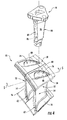
- FIG. 4 provides an exploded perspective view of a portion of the exemplary nozzle segment 50 as provided in FIG. 3 with the inner support ring 68 and the outer support ring 70 removed for clarity, according to various embodiments of the present disclosure.
- each stator component 52 includes a radial cooling channel 76.
- the radial cooling channel 76 extends and/or is defined radially through the outer band 58, the airfoil 54 and the inner band 56.
- the radial cooling channel 76 is in fluid communication with the cooling flow inlet 74 ( FIG. 3 ).
- the radial cooling channel 76 is in fluid communication with the rotor purge air passage 72 ( FIG. 3 ).
- the stator component 52 comprises a single radial cooling channel 76.
- the airfoil 54 may include a plurality of film holes 77 defined along an outer surface of the airfoil 54 and in fluid communication with the radial cooling channel 76 to provide film cooling to the outer surfaces and/or portions of the airfoil 54.
- the film holes 77 provide for localized bore or through-hole cooling of the airfoil 54.
- the airfoil 54 may include a plurality of film holes 77 along the pressure side wall 64 and/or the suction side wall 66 (not shown).
- the film holes 77 allow for localized bore or through-hole cooling of the airfoil 54 where hotspots may form.
- the film holes 77 may provide for bore cooling from about 50 percent to about 80 percent of the chord line.
- the airfoil 54 may further comprise film holes 77 in order to provide a desirable operating temperature for the airfoil 54.
- the airfoil 54 may include between 1 and 4 radially and/or axially spaced rows of the film holes 77.
- the films holes 77 may be from about 10 to about 30 mils in diameter.
- the rows of film holes 77 may be separated by about 1 to about 4 airfoil wall thicknesses of the airfoil 54.
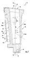
- FIG. 5 provides a cross sectioned side view of the nozzle segment 50 as shown in FIG. 3 , according to various embodiments of the present disclosure.
- at least one nozzle segment 50 includes an insert or strut 78.
- the strut 78 When installed, as shown in FIG. 5 , the strut 78 is positioned inside the radial cooling channel 76.
- the strut 78 may be connected to and/or in contact with the inner support ring 68 and/or the outer support ring 70.
- the strut 78 generally includes a forward portion 80 and an aft portion 82.
- the strut 78 further includes a pressure side portion 84 that extends between the forward and aft portions 80, 82 chord-wise and in span and a suction side portion 86 that extends between the forward and aft portions 80, 82 chord-wise and in span.
- one or more of the forward portion 80, aft portion 82, pressure side portion 84 and the suction side portion 86 are formed or shaped to be substantially complimentary with an inner surface 88 ( FIG. 4 ) of the airfoil 54.
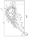
- FIG. 6 is a perspective view of the strut 78 as shown in FIG. 5 removed from the nozzle segment 50 for clarity according to various embodiments of the present disclosure.
- FIG. 7 is a cross sectional side view of the strut 78 taken along section line 7 as shown in FIG. 6 .
- the strut 78 defines an inner radial cooling passage 90.
- the strut 78 defines and/or includes an inlet 92 to the inner radial cooling passage 90.
- the inlet 92 is in fluid communication with the cooling medium source via the cooling air inlet 74 of the outer support ring 70.
- the strut 78 may also include an outlet 94 that is in fluid communication with the inner radial cooling passage 90.
- the outlet 94 may be in fluid communication with the purge air passage 72 of the inner support ring 68 ( FIG. 5 ).
- the strut 78 includes and/or defines a plurality of apertures 96(a-d). Apertures indicated as 96(a) are generally formed along the forward portion 80 of the strut 78, 96(b) are formed along the pressure side portion 84 of the strut 78, 96(c) are formed along the aft portion 82 of the strut 78 and 96(d) are formed along the suction side portion 86 of the strut 78.
- the apertures 96(a-d) provide for fluid communication from the inner radial cooling passage 90 through the strut 78 and into the radial cooling channel 76 of the airfoil 54. Any of the apertures 96(a-d) may be formed and/or angled so as to provide impingement or jet cooling to the inner surface 88 of the airfoil 54.
- At least one of the apertures 96(a-d) particularly shown but not limited to apertures 96(a) may be formed so as to direct a flow of compressed air at the inner surface 88 of the airfoil ( FIG. 8 ) at an angle ⁇ measured with respect to radial centerline 97 which is generally perpendicular with engine axis 40.
- at least one aperture 96(a) may be formed at an angle ⁇ that is acute with respect to a right angle formed with radial centerline 97, substantially perpendicular to radial centerline 97 or at an angle ⁇ that is obtuse with respect to a right angle formed with radial centerline 97.
- a deflector shield or baffle 98 extends span-wise and chord-wise from the pressure side portion 84 around the aft portion 82 and to the suction side portion 86 of the strut 78.
- the baffle 98 may extend radially in span between about 50 to 100 percent of the total radial span of the strut 78.
- the baffle 98 may have a thickness that is from about 5 to about 30 mils.
- the baffle 98 may be attached to the strut 78 via welded through-wall pins, with or without brazed edges or by any known suitable attaching means.
- the baffle 98 generally defines a flow passage 100 between the aft portion 82 of the strut 78 and the baffle 98.
- the flow passage 100 may be in fluid communication with the inner radial cooling passage 90 via one or more of the apertures 96(a-d).
- the flow passage 100 may be in fluid communication with the radial cooling channel 76 of the stator component 52.
- the baffle 98 may include and/or define one or more exhaust holes 102.
- FIG. 8 provides a cross sectional top view of one of the stator components 52 taken along section line 8-8 as shown in FIG. 3 including the airfoil 54, the strut 78, and the inner band 56, according to at least one embodiment of the present invention.
- FIG. 9 provides a cross sectional top view of one of the stator components 52 as shown in FIG. 8 including the airfoil 54, the strut 78, the baffle 98 and the inner band 56, according to at least one embodiment of the present invention.
- a chord line 104 is defined from the leading edge portion 60 to the trailing edge portion 62 of the airfoil 54.
- a distance taken between a starting point 106 of the chord line 104 and a termination point 108 of the chord line 104 is representative of one hundred percent of the chord length of the airfoil 54.
- the stator component 52 is formed form a Ceramic Matrix Composite material.
- the apertures 96(a-d) are positioned along the strut 78 between zero percent of the chord length and about sixty percent of the chord length of the airfoil 54 so as to provide impingement and/or convective cooling to the inner surface 88 of the airfoil 54.
- the film holes 77 are positioned along the airfoil 54 between about forty percent of the chord length of the airfoil 54 and about eighty percent of the chord length so as to provide film cooling to the pressure side wall 64 and/or the suction side wall 66.
- the trailing edge portion 62 of the airfoil 54 is solid (without film holes) between about seventy percent of the chord length and one hundred percent of the chord length.
- the apertures 96(a-d) are disposed between zero and sixty percent of the chord length
- the film holes 77 are disposed between forty percent and eighty percent of the chord length
- the trailing edge portion 62 of the airfoil 54 is solid from eighty percent of the chord length to the termination point 108 or one hundred percent of the chord line 104.
- the baffle 98 is connected to the strut 78 so as to prevent direct impingement cooling of the inner surface 88 of the airfoil 54 aft of the aft portion of the strut 78.
- the baffle 98 includes one or more of the exhaust holes 102 ( FIG. 7 ).
- the apertures 96(a-d) are positioned along the strut 78 between zero percent of the chord length and about sixty percent of the chord length of the airfoil 54 so as to provide impingement and/or convective cooling to the inner surface 88 of the airfoil 54.
- the film holes 77 are positioned along the airfoil 54 between about forty percent of the chord length of the airfoil 54 and about eighty percent of the chord length so as to provide film cooling to the pressure side wall 64 and/or the suction side wall 66.
- the trailing edge portion 62 of the airfoil 54 is solid between about seventy percent of the chord length and one hundred percent of the chord length.
- the apertures 96(a-d) are disposed between zero and sixty percent of the chord length
- the film holes 77 are disposed between forty percent and eighty percent of the chord length
- the trailing edge portion 62 of the airfoil 54 is solid from eighty percent of the chord length to the termination point 108 of the chord line 104.
- a cooling medium such as compressed air is directed through the inlet 92 of the strut 78 and into the inner radial cooling passage 90.
- the compressed air flows radially inwardly towards the outlet 94 of the strut 78.
- a portion of the compressed air as indicated by arrows flows through the various apertures 96(a-d) defined within the strut 78 and is impinged upon or directed towards the inner surface 88 of the airfoil 54 at various locations defined along the inner surface 88 of the airfoil 54 between zero percent and about 60 percent of the chord length, thus providing backside cooling to the airfoil 54.
- a portion of the compressed air is routed from the inner radial cooling passage 90 into the flow passage 100 defined by the baffle 98, thus preventing direct impingement cooling of the inner surface 88 of the airfoil 54 aft of the aft portion 82 of the strut 78.
- the compressed air may then flow from the flow passage 100 into the radial cooling channel 76, thus providing convection cooling to the inner surface 88 of the airfoil 54.
- at least a portion of the compressed air is then exhausted through the airfoil 54 from the film holes 77, thus providing bore or through-hole cooling and/or film cooling to various portions of the airfoil 54.
- a remaining portion of the compressed air may be routed from the outlet 94 of the strut 78 into the rotor purge air passage 72.
- the arrangement of the various apertures 96(a-d), the film holes 77 and the baffle 98 provide various technical benefits over known cooling schemes for airfoils of a stator component of a nozzle segment. For example, by positioning the apertures 96(a-d) to provide impingement cooling to the inner surface 88 of the airfoil 54 from zero to about 60 percent of the cord length of the airfoil 54, temperatures found within the radial cooling channel 76 may be closely matched with the temperature of the trailing edge temperatures, thus reducing through-wall and/or chordwise temperature gradients.
- the positioning of the apertures 96(a-d) provides flow to the trailing edge portion 62 of the airfoil 54 and to the inner and outer bands 56, 58 without requiring additional cooling to the leading edge portion 62 of the airfoil 54.
- the baffle 98 may provide a flow path for dedicated trailing edge 62 and inner and outer band 56, 58 cooling flow while potentially reducing direct impact on airfoil 54 stresses.
- the solid trailing edge portion 62 may be at least partially enabled by the cooling configuration provided herein. More specifically, the solid trailing edge portion 62 may be at least partially enabled by using impingement, bore and film cooling along the provided percentages of the chord length of the airfoil 54 to reduce airfoil temperature gradients between the cavity and trailing edge.
Applications Claiming Priority (1)
| Application Number | Priority Date | Filing Date | Title |
|---|---|---|---|
| US14/857,865 US11230935B2 (en) | 2015-09-18 | 2015-09-18 | Stator component cooling |
Publications (1)
| Publication Number | Publication Date |
|---|---|
| EP3144479A1 true EP3144479A1 (en) | 2017-03-22 |
Family
ID=56876960
Family Applications (1)
| Application Number | Title | Priority Date | Filing Date |
|---|---|---|---|
| EP16187331.0A Withdrawn EP3144479A1 (en) | 2015-09-18 | 2016-09-06 | Stator component cooling |
Country Status (5)
| Country | Link |
|---|---|
| US (1) | US11230935B2 (zh) |
| EP (1) | EP3144479A1 (zh) |
| JP (1) | JP2017072128A (zh) |
| CN (1) | CN106545365B (zh) |
| CA (1) | CA2941225A1 (zh) |
Cited By (7)
| Publication number | Priority date | Publication date | Assignee | Title |
|---|---|---|---|---|
| EP3502564A1 (en) * | 2017-12-19 | 2019-06-26 | United Technologies Corporation | Apparatus and method for mitigating particulate accumulation on a component of a gas turbine engine |
| WO2020068109A1 (en) * | 2018-09-28 | 2020-04-02 | Siemens Aktiengesellschaft | Modular cooling arrangement for cooling airfoil components in a gas turbine engine |
| CN111561357A (zh) * | 2020-05-25 | 2020-08-21 | 中国航发沈阳发动机研究所 | 一种进气机匣结构 |
| WO2020249886A1 (fr) * | 2019-06-12 | 2020-12-17 | Safran Aircraft Engines | Turbine de turbomachine a distributeur en cmc avec reprise d'effort |
| WO2020263396A1 (en) * | 2019-06-28 | 2020-12-30 | Siemens Aktiengesellschaft | Turbine airfoil incorporating modal frequency response tuning |
| EP3819472A1 (en) * | 2019-11-07 | 2021-05-12 | Raytheon Technologies Corporation | Airfoil vane, corresponding method of making a baffle and method of assembling a ceramic matrix composite airfoil vane |
| US11215073B2 (en) | 2018-04-24 | 2022-01-04 | MTU Aero Engines AG | Stator vane for a turbine of a turbomachine |
Families Citing this family (12)
| Publication number | Priority date | Publication date | Assignee | Title |
|---|---|---|---|---|
| US9915159B2 (en) * | 2014-12-18 | 2018-03-13 | General Electric Company | Ceramic matrix composite nozzle mounted with a strut and concepts thereof |
| GB201612293D0 (en) * | 2016-07-15 | 2016-08-31 | Rolls Royce Plc | Assembly for supprting an annulus |
| US10626797B2 (en) * | 2017-02-15 | 2020-04-21 | General Electric Company | Turbine engine compressor with a cooling circuit |
| US10502069B2 (en) * | 2017-06-07 | 2019-12-10 | General Electric Company | Turbomachine rotor blade |
| FR3072711B1 (fr) | 2017-10-19 | 2021-07-16 | Safran Aircraft Engines | Element de repartition d'un fluide de refroidissement et ensemble d'anneau de turbine associe |
| US20190309631A1 (en) * | 2018-04-04 | 2019-10-10 | United Technologies Corporation | Airfoil having leading edge cooling scheme with backstrike compensation |
| US11047258B2 (en) * | 2018-10-18 | 2021-06-29 | Rolls-Royce Plc | Turbine assembly with ceramic matrix composite vane components and cooling features |
| US11415002B2 (en) * | 2019-10-18 | 2022-08-16 | Raytheon Technologies Corporation | Baffle with impingement holes |
| US11428166B2 (en) | 2020-11-12 | 2022-08-30 | Solar Turbines Incorporated | Fin for internal cooling of vane wall |
| US11591921B1 (en) * | 2021-11-05 | 2023-02-28 | Rolls-Royce Plc | Ceramic matrix composite vane assembly |
| US11873737B1 (en) * | 2022-07-22 | 2024-01-16 | Pratt & Whitney Canada Corp. | Flow deflector for aperture in gas turbine engine flowpath wall |
| US11913348B1 (en) * | 2022-10-12 | 2024-02-27 | Rtx Corporation | Gas turbine engine vane and spar combination with variable air flow path |
Citations (4)
| Publication number | Priority date | Publication date | Assignee | Title |
|---|---|---|---|---|
| JPS5847103A (ja) * | 1981-09-11 | 1983-03-18 | Agency Of Ind Science & Technol | ガスタ−ビン翼 |
| WO2011021693A1 (ja) * | 2009-08-21 | 2011-02-24 | 株式会社Ihi | タービン用冷却構造、及び、タービン |
| WO2014158278A2 (en) * | 2013-03-04 | 2014-10-02 | Rolls-Royce North American Technologies, Inc. | Compartmentalization of cooling flow in a structure comprising a cmc component |
| WO2016111773A1 (en) * | 2015-01-09 | 2016-07-14 | Solar Turbines Incorporated | Crimped insert for improved turbine vane internal cooling |
Family Cites Families (35)
| Publication number | Priority date | Publication date | Assignee | Title |
|---|---|---|---|---|
| JPS5847103B2 (ja) | 1976-11-09 | 1983-10-20 | 日本電気株式会社 | 無線回線擬似方式 |
| US4314442A (en) | 1978-10-26 | 1982-02-09 | Rice Ivan G | Steam-cooled blading with steam thermal barrier for reheat gas turbine combined with steam turbine |
| JPS5672201A (en) | 1979-11-14 | 1981-06-16 | Hitachi Ltd | Cooling structure of gas turbine blade |
| JPS58161103U (ja) * | 1982-04-22 | 1983-10-27 | 三菱重工業株式会社 | ガスタ−ビン空冷翼 |
| JPS6143927A (ja) | 1984-08-07 | 1986-03-03 | 井関農機株式会社 | 刈取機における刈取搬送支持装置 |
| US5207556A (en) * | 1992-04-27 | 1993-05-04 | General Electric Company | Airfoil having multi-passage baffle |
| US5702232A (en) | 1994-12-13 | 1997-12-30 | United Technologies Corporation | Cooled airfoils for a gas turbine engine |
| US5839878A (en) * | 1996-09-30 | 1998-11-24 | United Technologies Corporation | Gas turbine stator vane |
| US5746573A (en) * | 1996-12-31 | 1998-05-05 | Westinghouse Electric Corporation | Vane segment compliant seal assembly |
| GB2343486B (en) * | 1998-06-19 | 2000-09-20 | Rolls Royce Plc | Improvemnts in or relating to cooling systems for gas turbine engine airfoil |
| WO2000053896A1 (de) | 1999-03-09 | 2000-09-14 | Siemens Aktiengesellschaft | Turbinenschaufel und verfahren zur herstellung einer turbinenschaufel |
| US6398501B1 (en) | 1999-09-17 | 2002-06-04 | General Electric Company | Apparatus for reducing thermal stress in turbine airfoils |
| US6200092B1 (en) | 1999-09-24 | 2001-03-13 | General Electric Company | Ceramic turbine nozzle |
| US6325593B1 (en) | 2000-02-18 | 2001-12-04 | General Electric Company | Ceramic turbine airfoils with cooled trailing edge blocks |
| US6554563B2 (en) | 2001-08-13 | 2003-04-29 | General Electric Company | Tangential flow baffle |
| US6769865B2 (en) * | 2002-03-22 | 2004-08-03 | General Electric Company | Band cooled turbine nozzle |
| FR2851286B1 (fr) * | 2003-02-18 | 2006-07-28 | Snecma Moteurs | Aubes de turbine refroidie a fuite d'air de refroidissement reduite |
| US7008185B2 (en) * | 2003-02-27 | 2006-03-07 | General Electric Company | Gas turbine engine turbine nozzle bifurcated impingement baffle |
| US7066717B2 (en) | 2004-04-22 | 2006-06-27 | Siemens Power Generation, Inc. | Ceramic matrix composite airfoil trailing edge arrangement |
| GB0703827D0 (en) | 2007-02-28 | 2007-04-11 | Rolls Royce Plc | Rotor seal segment |
| US8251652B2 (en) | 2008-09-18 | 2012-08-28 | Siemens Energy, Inc. | Gas turbine vane platform element |
| US8070442B1 (en) | 2008-10-01 | 2011-12-06 | Florida Turbine Technologies, Inc. | Turbine airfoil with near wall cooling |
| US8956105B2 (en) | 2008-12-31 | 2015-02-17 | Rolls-Royce North American Technologies, Inc. | Turbine vane for gas turbine engine |
| US8096767B1 (en) | 2009-02-04 | 2012-01-17 | Florida Turbine Technologies, Inc. | Turbine blade with serpentine cooling circuit formed within the tip shroud |
| US8262345B2 (en) | 2009-02-06 | 2012-09-11 | General Electric Company | Ceramic matrix composite turbine engine |
| US8449249B2 (en) * | 2010-04-09 | 2013-05-28 | Williams International Co., L.L.C. | Turbine nozzle apparatus and associated method of manufacture |
| US8535006B2 (en) | 2010-07-14 | 2013-09-17 | Siemens Energy, Inc. | Near-wall serpentine cooled turbine airfoil |
| JP5931351B2 (ja) | 2011-05-13 | 2016-06-08 | 三菱重工業株式会社 | タービン静翼 |
| US9915154B2 (en) * | 2011-05-26 | 2018-03-13 | United Technologies Corporation | Ceramic matrix composite airfoil structures for a gas turbine engine |
| EP2626519A1 (en) * | 2012-02-09 | 2013-08-14 | Siemens Aktiengesellschaft | Turbine assembly, corresponding impingement cooling tube and gas turbine engine |
| US9230055B2 (en) * | 2012-04-05 | 2016-01-05 | The United States Of America As Represented By The Secretary Of The Air Force | Method of optimizing film cooling performance for turbo-machinery components |
| US9546557B2 (en) | 2012-06-29 | 2017-01-17 | General Electric Company | Nozzle, a nozzle hanger, and a ceramic to metal attachment system |
| EP2703601B8 (en) * | 2012-08-30 | 2016-09-14 | General Electric Technology GmbH | Modular Blade or Vane for a Gas Turbine and Gas Turbine with Such a Blade or Vane |
| EP2956625B1 (en) * | 2013-02-18 | 2017-11-29 | United Technologies Corporation | Stress mitigation feature for composite airfoil leading edge |
| JP5908054B2 (ja) | 2014-11-25 | 2016-04-26 | 三菱重工業株式会社 | ガスタービン |
-
2015
- 2015-09-18 US US14/857,865 patent/US11230935B2/en active Active
-
2016
- 2016-09-06 EP EP16187331.0A patent/EP3144479A1/en not_active Withdrawn
- 2016-09-07 JP JP2016174165A patent/JP2017072128A/ja active Pending
- 2016-09-08 CA CA2941225A patent/CA2941225A1/en not_active Abandoned
- 2016-09-14 CN CN201610822564.2A patent/CN106545365B/zh active Active
Patent Citations (4)
| Publication number | Priority date | Publication date | Assignee | Title |
|---|---|---|---|---|
| JPS5847103A (ja) * | 1981-09-11 | 1983-03-18 | Agency Of Ind Science & Technol | ガスタ−ビン翼 |
| WO2011021693A1 (ja) * | 2009-08-21 | 2011-02-24 | 株式会社Ihi | タービン用冷却構造、及び、タービン |
| WO2014158278A2 (en) * | 2013-03-04 | 2014-10-02 | Rolls-Royce North American Technologies, Inc. | Compartmentalization of cooling flow in a structure comprising a cmc component |
| WO2016111773A1 (en) * | 2015-01-09 | 2016-07-14 | Solar Turbines Incorporated | Crimped insert for improved turbine vane internal cooling |
Cited By (11)
| Publication number | Priority date | Publication date | Assignee | Title |
|---|---|---|---|---|
| EP3502564A1 (en) * | 2017-12-19 | 2019-06-26 | United Technologies Corporation | Apparatus and method for mitigating particulate accumulation on a component of a gas turbine engine |
| US11215073B2 (en) | 2018-04-24 | 2022-01-04 | MTU Aero Engines AG | Stator vane for a turbine of a turbomachine |
| WO2020068109A1 (en) * | 2018-09-28 | 2020-04-02 | Siemens Aktiengesellschaft | Modular cooling arrangement for cooling airfoil components in a gas turbine engine |
| WO2020249886A1 (fr) * | 2019-06-12 | 2020-12-17 | Safran Aircraft Engines | Turbine de turbomachine a distributeur en cmc avec reprise d'effort |
| FR3097264A1 (fr) * | 2019-06-12 | 2020-12-18 | Safran Aircraft Engines | Turbine de turbomachine à distributeur en CMC avec reprise d’effort |
| WO2020263396A1 (en) * | 2019-06-28 | 2020-12-30 | Siemens Aktiengesellschaft | Turbine airfoil incorporating modal frequency response tuning |
| EP3819472A1 (en) * | 2019-11-07 | 2021-05-12 | Raytheon Technologies Corporation | Airfoil vane, corresponding method of making a baffle and method of assembling a ceramic matrix composite airfoil vane |
| US11506063B2 (en) | 2019-11-07 | 2022-11-22 | Raytheon Technologies Corporation | Two-piece baffle |
| US11905854B2 (en) | 2019-11-07 | 2024-02-20 | Rtx Corporation | Two-piece baffle |
| CN111561357A (zh) * | 2020-05-25 | 2020-08-21 | 中国航发沈阳发动机研究所 | 一种进气机匣结构 |
| CN111561357B (zh) * | 2020-05-25 | 2022-07-15 | 中国航发沈阳发动机研究所 | 一种进气机匣结构 |
Also Published As
| Publication number | Publication date |
|---|---|
| US11230935B2 (en) | 2022-01-25 |
| US20170081966A1 (en) | 2017-03-23 |
| CN106545365A (zh) | 2017-03-29 |
| JP2017072128A (ja) | 2017-04-13 |
| CA2941225A1 (en) | 2017-03-18 |
| CN106545365B (zh) | 2020-08-18 |
Similar Documents
| Publication | Publication Date | Title |
|---|---|---|
| US11230935B2 (en) | Stator component cooling | |
| US10408073B2 (en) | Cooled CMC wall contouring | |
| US10815789B2 (en) | Impingement holes for a turbine engine component | |
| EP3255248A1 (en) | Engine component for a turbine engine | |
| US10605170B2 (en) | Engine component with film cooling | |
| US20160123186A1 (en) | Shroud assembly for a turbine engine | |
| US11359498B2 (en) | Turbine engine airfoil assembly | |
| US20190218925A1 (en) | Turbine engine shroud | |
| EP3211314A1 (en) | Components for a gas turbine engine and corresponding cooling method | |
| CN109083688B (zh) | 具有偏转器的涡轮发动机部件 | |
| EP3431710A1 (en) | Shield for a turbine engine airfoil | |
| US20190249554A1 (en) | Engine component with cooling hole | |
| US10443407B2 (en) | Accelerator insert for a gas turbine engine airfoil | |
| CN107461225B (zh) | 用于燃气涡轮发动机的喷嘴冷却系统 | |
| US11377963B2 (en) | Component for a turbine engine with a conduit | |
| US20180128113A1 (en) | Airfoil assembly with a cooling circuit | |
| US11225872B2 (en) | Turbine blade with tip shroud cooling passage | |
| US10697313B2 (en) | Turbine engine component with an insert | |
| US11401835B2 (en) | Turbine center frame |
Legal Events
| Date | Code | Title | Description |
|---|---|---|---|
| PUAI | Public reference made under article 153(3) epc to a published international application that has entered the european phase |
Free format text: ORIGINAL CODE: 0009012 |
|
| AK | Designated contracting states |
Kind code of ref document: A1 Designated state(s): AL AT BE BG CH CY CZ DE DK EE ES FI FR GB GR HR HU IE IS IT LI LT LU LV MC MK MT NL NO PL PT RO RS SE SI SK SM TR |
|
| AX | Request for extension of the european patent |
Extension state: BA ME |
|
| 17P | Request for examination filed |
Effective date: 20170922 |
|
| RBV | Designated contracting states (corrected) |
Designated state(s): AL AT BE BG CH CY CZ DE DK EE ES FI FR GB GR HR HU IE IS IT LI LT LU LV MC MK MT NL NO PL PT RO RS SE SI SK SM TR |
|
| STAA | Information on the status of an ep patent application or granted ep patent |
Free format text: STATUS: THE APPLICATION IS DEEMED TO BE WITHDRAWN |
|
| 18D | Application deemed to be withdrawn |
Effective date: 20170923 |