EP3144211B1 - Aquatic vehicle with at least one elastically deformable component and method for detecting the onset of a wear-related component remaining life on a watercraft - Google Patents
Aquatic vehicle with at least one elastically deformable component and method for detecting the onset of a wear-related component remaining life on a watercraft Download PDFInfo
- Publication number
- EP3144211B1 EP3144211B1 EP16001985.7A EP16001985A EP3144211B1 EP 3144211 B1 EP3144211 B1 EP 3144211B1 EP 16001985 A EP16001985 A EP 16001985A EP 3144211 B1 EP3144211 B1 EP 3144211B1
- Authority
- EP
- European Patent Office
- Prior art keywords
- component
- deformation
- operating life
- measuring
- aquatic vehicle
- Prior art date
- Legal status (The legal status is an assumption and is not a legal conclusion. Google has not performed a legal analysis and makes no representation as to the accuracy of the status listed.)
- Not-in-force
Links
Images


Classifications
-
- B—PERFORMING OPERATIONS; TRANSPORTING
- B63—SHIPS OR OTHER WATERBORNE VESSELS; RELATED EQUIPMENT
- B63B—SHIPS OR OTHER WATERBORNE VESSELS; EQUIPMENT FOR SHIPPING
- B63B71/00—Designing vessels; Predicting their performance
-
- G—PHYSICS
- G05—CONTROLLING; REGULATING
- G05B—CONTROL OR REGULATING SYSTEMS IN GENERAL; FUNCTIONAL ELEMENTS OF SUCH SYSTEMS; MONITORING OR TESTING ARRANGEMENTS FOR SUCH SYSTEMS OR ELEMENTS
- G05B19/00—Programme-control systems
- G05B19/02—Programme-control systems electric
- G05B19/18—Numerical control [NC], i.e. automatically operating machines, in particular machine tools, e.g. in a manufacturing environment, so as to execute positioning, movement or co-ordinated operations by means of programme data in numerical form
Definitions
- the invention relates to a watercraft with a drive unit and with at least one elastically deformable component as a structural part and / or bearing part according to the preamble of claim 1.
- watercraft are here understood all sorts of motorized vessels such as passenger ships, ferries, cruise ships, freighters, oil tankers, pleasure boats or the like, in which elastically deformable component as structural parts and / or bearing parts in operation depending on changing driving conditions different deformation forces act, ultimately lead to a component wear duration limiting component wear.
- elastically deformable components are in particular rubber-metal bearings as engine bearings and / or gearbox bearings and / or elastic couplings.
- these are structural parts made of plastic, in particular fiber composite materials.
- rubber-metal bearing is also to be understood generally and to be interpreted broadly, “rubber” being synonymous with “elastomer material” and “metal” for a deformation-resistant bearing component, which in particular also consists of plastic can.
- Such rubber-metal bearings and / or plastic parts, in particular fiber composite parts are known to function reliably with proper design over a long service life even at high oscillating loads and in principle wear-free.
- a criterion for the function of such a component is the deformation under force or the corresponding component rigidity.
- the component life is measured in a known manner on a test bed at clearly defined ratios.
- a rubber-metal bearing is subjected to oscillating loads.
- the load changes or repetitive load blocks are counted and thereby force and deformation are measured, whereby one of the two values is specified.
- a diagram is generated as a measuring curve, in which a falling stiffness over the number of load changes is recognizable.
- the number of load changes can be interpreted directly as service life. From such a diagram, an increase in deformation corresponding to a decrease in rigidity in characteristic three stages can be seen in each case over the service life.
- the stiffness drops very quickly, for example, by about 30%, which is referred to as flowing and setting.
- a very small drop in rigidity is measured, corresponding to a plateau course with a linear and / or slight drop in rigidity.
- a measurable comparatively rapid progressive drop in rigidity which marks the near end of the component function with a possible failure and thus the end of its useful life.
- the incipient end of the useful life according to the third diagram stage can be detected relatively easily, for example by a change in noise or in a road vehicle by a changed driving behavior.
- incipient damage according to the third diagram stage may also be visually recognized.
- simple checks are not possible, so that a component damage can lead to a security risk and / or expensive consequential damage and breakdowns.
- the object of the invention is to determine the possible component service life in a watercraft with at least one elastically deformable component as a structural part and / or bearing part more accurate than is possible by test bench measurements and estimates.
- each same drive state can be predetermined, which is assigned a specific, each same deformation force.
- a detection unit is provided which is set up so that in each case one such predetermined drive state is detected and detected.
- a drive state is selected and determined, which occurs relatively frequently with a clearly measurable component deformation, so that a relatively large number of evaluable measurement results can be obtained.
- load levels with a relatively high proportion of damage, in particular lasting, high oscillating loads on the component, should occur. It is assumed that with largely identical drive states of the Watercraft are thus also largely the same deformation forces occurring on the component. In principle, several different drive states could also be predetermined for several parallel evaluations or for evaluations on several components installed in the watercraft.
- a start signal is generated, whereby a measuring operation is started, for a component monitoring with at least one component associated sensor and a downstream measuring and evaluation unit
- component deformation as a parameter for a current component stiffness is measurable and the measured value can be stored.
- the deformation force acting on the component need not be measured absolutely. Neither is it necessary to measure the component deformation or its reciprocal value as component stiffness absolutely, since in the further evaluation only relative values and tendencies between successive measured values are used. It is also not absolutely necessary to determine a drive state for the start signal and the measurement completely precisely, since the predetermination of a narrow "drive window" delivers well usable results, which should be included here.
- a measurement curve from the measured values to compensate for measurement tolerances must be averaged and smoothed.
- the uncritical plateau area is clearly associated with a sharp increase in the slope of a measurement curve with respect to the component deformation or a sharp decrease in inclination of a measurement curve leave the component stiffness. If such a threshold value predeterminable increase in slope or inclination drop is determined, thus the beginning of a wear-related predefinable component remaining service life can be determined.
- a corresponding warning information for example, as an optical or acoustic signal can be output, which indicates a required component replacement. This second result is when the third stage in the stiffness diagram described above is reached.
- the core of the invention is thus a qualitative determination of the stiffness of the deformable component, which is not directly controllable and measurable in the installed state in the vessel. Only in the knowledge of a force and deformation, such as on a test bench, can the stiffness be determined absolutely. In a technical application, it is not possible with reasonable effort to measure the force applied to a built-in component force. Paths or deformations, however, are relatively easy to measure in a conventional manner. The determination of the component life is advantageously carried out according to the invention only by evaluations of measured value that are to be carried out simply.
- a measurement of the component deformation is triggered in each case.
- the time corresponding to the occurrence of a predetermined drive state is selected such that load levels with clearly measurable deformations and preferably with a high percentage of damage occur.
- the damage component is achieved by a frequent occurrence of this load level and not by high loads with low frequency in order to obtain a large number of measurement results whose inevitable scattering is thus better than scattering and not as looming component damage can be assessed.
- the number of measured values obtained is expediently plotted on the X-axis of a diagram.
- the deformation can be applied on the Y-axis. However, it is visually more understandable to apply their inverse, one by the deformation, thus obtaining a measurement curve analogous to the course of the rigidity. This shows in a first stage at the beginning of the component life a strong drop in stiffness by flowing and setting, which is followed in a second stage, a plateau region with slightly linearly decreasing stiffness over the lifetime, and at the end of Useful life in a third stage is a highly progressive waste.
- a straight line is determined as the measuring curve, which maps the described plateau well in its course, whereby this is possible after only a few measured values in the plateau region.
- Each additional measured value is evaluated in terms of how it changes or deviates from the characteristic of the previously determined straight line.
- a change in the slope of this straight line is used as the criterion for an evaluation. If, after the plateau area, the magnitude of the slope increases significantly above the value of scattering over several measured values, then the region of progressive stiffness decrease begins as a signal for replacement of the component. In principle, therefore, the differential of the averaged trace is evaluated.
- the state of wear of a deformable component is advantageously determined directly and directly during its component service life.
- a component can be used over its actual life to the beginning of its progressive stiffness drop.
- pre-emptive replacement measures predefined prior to the actually possible end of use can be dispensed with by means of useful life estimates, thereby saving on maintenance and operating costs.
- the component safety is increased by the measurement on the component and the risk of possible follow-up costs in case of a non-recognized component failure is reduced.
- the predetermined drive state can be detected directly as a predetermined engine power of the drive unit.
- a current engine speed or corresponding vibration frequency can be utilized by additionally using existing measuring signals in the vessel anyway.
- optionally low-frequency Suggestions by wave shock and / or sea state with a low-pass filter are filtered out.
- a single measuring process can be started and carried out in each case.
- a further measuring process can be automatically started and carried out again after a predetermined waiting time, even if the operating state has been stopped for a long time.
- Particularly suitable for the monitoring according to the invention are the initially mentioned, elastically deformable components of a watercraft as rubber-metal bearings and as structural parts.
- a temperature window of 6 ° C should be maintained as a further condition for the start of a measurement process and / or for the utilization of a measured value, this temperature window in a temperature range from 0 ° C to 35 ° C can be selected. It is taken into account that temperature influences at temperatures below 0 ° C and above 35 ° C lead to strong, unfavorable measured value fluctuations. The temperature influence on the measured values in a temperature window of 6 ° C within the temperature range of 0 ° C to 35 ° C, however, is negligible for the evaluation according to the invention.
- a measured value counter corresponding to a service life is nevertheless set high in order not to distort the measured curve, in particular the stiffness course.
- a sensor for measuring a displacement and / or a speed and / or an acceleration can be used as a sensor for measuring the component deformation.
- a deformation can be measured directly or indirectly between component components and / or attachments.
- the sensor system can be integrated in the deformable component, in particular in an elastomer, and / or arranged on adjoining / adjacent attachment parts.
- a distance can be measured directly as component deformation by having a signal generator on the inside of a rubber-metal bearing and a sensor on the outside. It is also possible to measure the accelerations in the elements, to integrate twice and to add, so that the relative path is obtained.
- known simple inductive displacement transducers, magnetoresistive sensors, Hall probes, acceleration sensors or other sensors can be used, with which a displacement, a velocity, an acceleration or another displacement-equivalent signal can be measured.
- the detection unit and the measurement and evaluation unit are expediently fully or partially integrated with their central electronics, which are usually present in the watercraft, whereby measured values, for example engine speed values, which are already available anyway for other purposes may also be used.
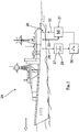
- Fig. 1 schematically is a watercraft 25, exemplified as a research vessel with a (not shown) internal drive unit that can be operated with different engine power corresponding to different engine speeds.
- a detection unit 27 is supplied with a motor speed signal via a control line 28.
- a triggering pulse is generated with a switching unit 30 for starting, possibly for repeatedly starting a measurement process for a deformation measurement by the measuring and evaluation unit 31 (control line 32). Recorded measured values are supplied via the measuring line 33 of the measuring and evaluation unit 31 and according to the flowchart according to Fig. 2 processed.
- Fig. 1 the process sequence is represented by status / process rectangles and decision diamond:
- the system is ready for measuring the component service life.
- a rubber-metal bearing is assumed in the installed as an engine mount 26 state.
- Such a trigger signal for a measurement start becomes corresponding Fig. 1 output when a predetermined engine power is output in a power window 29.
- decision diamond 4 is also checked whether a predetermined temperature window is met in the measurement.
- additional boundary conditions may optionally also be specified, for example a wave window or draft window corresponding to a loading window.
- the measured value counter is nevertheless counted up in order to largely reduce otherwise given distortions of the measuring curve (rectangle 5).
- decision diamond 7 it is determined whether values for the deformation are present, this is not the case, the current measurement and evaluation cycle is terminated.
- Fig. 3 is a diagram of a typical measurement curve 14 for a component use of an elastically deformable component, here for example for a rubber-metal bearing of the vessel at successive within same limits and time-shifted loads shown.
- the respectively determined parameter for the stiffness is plotted upward on the Y-axis as 1 divided by deformation.
- the number of measured values is plotted, which can be interpreted as a useful life, with an existing measured value in the diagram is shown as a measuring point 15 with equal intervals for each predetermined drive state.
- the measuring points 15 scatter in an insignificant extent to an extent that is only insignificant for the useful life and for the statement to be made.
- the evaluation is therefore interpolated with the following result:
- the stiffness drops relatively quickly due to flowing and setting.
- the second stiffness region 17 which can be indicated by a straight line 18 by averaging out the measured value scattering, a plateau region is characterized by only a very small drop in stiffness. In the diagram, this stiffness range is shown for a better illustration with a relatively large inclination of the straight line 18.
- the second stiffness region 17 as a plateau region in comparison to the first and third stiffness region 16, 19 is shown substantially shortened / longer with many measured values 15 and here for a better clarification of the principal course of the measurement curve.
- a rapid progressive drop in stiffness is detected as an indication of a soon to be required replacement of the component corresponding to the rectangle 12 Fig. 1 .
- This progressive stiffness drop as a significant deviation from the Extension 20 of the straight line 18 can be detected quickly and easily shortly after it starts (for example, with the measured value 21).
Description
Die Erfindung betrifft ein Wasserfahrzeug mit einem Antriebsaggregat und mit wenigstens einem elastisch verformbaren Bauteil als Strukturteil und/oder Lagerteil nach dem Oberbegriff des Anspruchs 1.The invention relates to a watercraft with a drive unit and with at least one elastically deformable component as a structural part and / or bearing part according to the preamble of claim 1.
Der Schiffverkehr mit Wasserfahrzeugen jeglicher Art, die geschäftlich zur Beförderung von Personen und Waren genutzt werden, ebenso wie der Sportbootbereich, nimmt weiter mit steigender Anzahl von Schiffen zu. Obwohl die meisten benutzten Wasserfahrzeuge einen hohen technischen Entwicklungsstandard aufweisen, ist deren sicherer Betrieb bei möglichst geringen Betriebs- und Wartungskosten eine ständige Herausforderung. Ein Problem ist dabei die Abschätzung der Nutzungsdauer von elastisch verformbaren Bauteilen.The shipping of vessels of any kind used for the transport of persons and goods on business, as well as the recreational craft area, continues to increase as the number of vessels increases. Although most of the vessels used have a high level of technical development, their safe operation at the lowest possible operating and maintenance costs is a constant challenge. One problem is the estimation of the service life of elastically deformable components.
Unter "Wasserfahrzeug" werden hier alle möglichen motorisierten Schiffe wie Personenschiffe, Fähren, Kreuzfahrtschiffe, Frachter, Öltanker, Sportboote oder ähnliche verstanden, bei denen auf elastisch verformbare Bauteil als Strukturteile und/oder Lagerteile im Betrieb abhängig von wechselnden Antriebszuständen unterschiedliche Verformungskräfte einwirken, die letztendlich zu einem die Bauteilnutzungsdauer begrenzenden Bauteilverschleiß führen. Solche elastisch verformbaren Bauteile sind insbesondere Gummi-Metalllager als Motorlager und/oder Getriebelager und/oder elastische Kupplungen. Weiter sind dies Strukturteile aus Kunststoff, insbesondere aus Faserverbundwerkstoffen.By "watercraft" are here understood all sorts of motorized vessels such as passenger ships, ferries, cruise ships, freighters, oil tankers, pleasure boats or the like, in which elastically deformable component as structural parts and / or bearing parts in operation depending on changing driving conditions different deformation forces act, ultimately lead to a component wear duration limiting component wear. Such elastically deformable components are in particular rubber-metal bearings as engine bearings and / or gearbox bearings and / or elastic couplings. Further, these are structural parts made of plastic, in particular fiber composite materials.
Auch der weiter verwendete Begriff "Gummi-Metalllager" ist, wie in Fachkreisen üblich, allgemein zu verstehen und weit auszulegen, wobei "Gummi" als Synonym für "Elastomermaterial" und "Metall" für ein verformungssteifes Lagerbauteil steht, das insbesondere auch aus Kunststoff bestehen kann.The term "rubber-metal bearing", as used in the art, is also to be understood generally and to be interpreted broadly, "rubber" being synonymous with "elastomer material" and "metal" for a deformation-resistant bearing component, which in particular also consists of plastic can.
Solche Gummi-Metalllager und/oder Kunststoffteile, insbesondere Faserverbundteile, sind bekanntlich bei richtiger Auslegung über eine lange Nutzungsdauer auch bei hohen oszillierenden Belastungen funktionssicher und im Prinzip verschleißfrei. Ein Kriterium für die Funktion eines solchen Bauteils ist die Verformung unter Krafteinwirkung bzw. die entsprechende Bauteilsteifigkeit.Such rubber-metal bearings and / or plastic parts, in particular fiber composite parts are known to function reliably with proper design over a long service life even at high oscillating loads and in principle wear-free. A criterion for the function of such a component is the deformation under force or the corresponding component rigidity.
An Muster-Bauteilen und an Kontroll-Bauteilen einer Serie wird in bekannter Weise die Bauteilnutzungsdauer auf einem Prüfstand bei klar definierten Verhältnissen gemessen. Dazu wird beispielsweise ein Gummi-Metall-Lager mit oszillierenden Belastungen beaufschlagt. Es werden die Lastwechsel oder sich wiederholende Lastblöcke gezählt und dabei werden Kraft und Verformung gemessen, wobei einer der beiden Werte vorgegeben wird. Daraus wird ein Diagramm als Messkurve erzeugt, in dem eine abfallende Steifigkeit über die Zahl der Lastwechsel erkennbar ist. Die Zahl der Lastwechsel ist unmittelbar als Nutzungsdauer interpretierbar. Aus einem solchen Diagramm ist jeweils im Laufe der Nutzungsdauer eine Zunahme der Verformung entsprechend einem Abfall der Steifigkeit in charakteristischen drei Stufen erkennbar. In der ersten Stufe fällt die Steifigkeit sehr schnell, beispielsweise um zirka 30% ab, was als Fließen und Setzen bezeichnet wird. Anschließend wird über eine vergleichsweise sehr lange Nutzungsdauer nur ein sehr geringer Abfall der Steifigkeit gemessen entsprechend einem Plateauverlauf mit linearem und/oder leichtem Abfall der Steifigkeit. Daran schließt sich ein messbarer vergleichsweise zügiger progressiver Abfall der Steifigkeit an, welcher das nahe Ende der Bauteilfunktion mit einem möglichen Ausfall und damit das Ende der Nutzungsdauer markiert.On sample components and control components of a series, the component life is measured in a known manner on a test bed at clearly defined ratios. For this purpose, for example, a rubber-metal bearing is subjected to oscillating loads. The load changes or repetitive load blocks are counted and thereby force and deformation are measured, whereby one of the two values is specified. From this, a diagram is generated as a measuring curve, in which a falling stiffness over the number of load changes is recognizable. The number of load changes can be interpreted directly as service life. From such a diagram, an increase in deformation corresponding to a decrease in rigidity in characteristic three stages can be seen in each case over the service life. In the first stage, the stiffness drops very quickly, for example, by about 30%, which is referred to as flowing and setting. Subsequently, over a comparatively very long service life, only a very small drop in rigidity is measured, corresponding to a plateau course with a linear and / or slight drop in rigidity. This is followed by a measurable comparatively rapid progressive drop in rigidity, which marks the near end of the component function with a possible failure and thus the end of its useful life.
Der Grund für dieses messbare Verhalten insbesondere eines Gummi-Metall-Lagers liegt darin, dass bei dauernden hohen oszillierenden Belastungen durch anliegende Kräftemomente oder durch aufgezwungene Verformungen Molekülketten aufreißen, die sich dann wegen der anliegenden Wechsellasten nicht mehr regenerieren können. Insbesondere in der dritten Stufe potenzieren sich diese Vorgänge und es kommt auch zu optisch erkennbaren Rissen und Schäden, die mit einem schnellen Abfall der Bauteilsteifigkeit zu einem beginnenden Ende der Nutzungsfunktion und letztendlich zu einem Ausfall führen. Ausgehend von Messungen der Nutzungsdauer auf einem Prüfstand wird dann mit Sicherheitsabschlägen für fertigungsbedingte Toleranzen und differierende reale Bauteilbelastungen eine Nutzungsdauer für Serienteile im Einbauzustand abgeschätzt und angegeben. Eine übliche typische Nutzungsdauer entsprechend der ersten und zweiten Stufe des oben genannten Diagramms liegt in der Größenordnung von 6 bis 10 Jahren. Wenn die dritte Diagrammstufe erreicht ist, muss zwar ein Gummi-Metall-Lager zeitnah ausgetauscht werden, kann aber noch über mehrere Wochen, gegebenenfalls Monate bis zu einem Totalausfall weiter verwendet werden.The reason for this measurable behavior, especially of a rubber-metal bearing, is that in the case of continuous high oscillating loads caused by applied force moments or imposed deformations, molecular chains are ruptured which then can no longer regenerate due to the applied alternating loads. In particular, in the third stage, these processes potentiate and there are also visually recognizable cracks and damage that lead to a rapid decline in component stiffness to a beginning end of the utilization function and ultimately to a failure. On the basis of measurements of the service life on a test bench, a service life for serial parts in the installed state is then estimated and indicated with safety deductions for production-related tolerances and differing real component loads. A typical typical service life corresponding to the first and second stages of the above diagram is on the order of 6 to 10 years. When the third diagram stage is reached, a rubber-metal bearing must be replaced in a timely manner, but can still be used for several weeks, possibly months to a total failure.
Ähnlich den vorstehend in Verbindung mit einem Gummi-Metall-Lager erläuterten Steifigkeitsverlauf verhält sich bei entsprechenden Belastungen üblicherweise auch ein Kunststoffteil, insbesondere ein Faserverbundbauteil, bei dem sich durch oszillierende Belastungen und erzwungene Verformungen der Faserverbund lockert und auflöst.Similar to the above explained in connection with a rubber-metal bearing stiffness behavior behaves at corresponding loads usually also a plastic part, in particular a fiber composite component, which loosens and dissolves due to oscillating loads and forced deformations of the fiber composite.
Bei vielen Anwendungen solcher Bauteile kann das beginnende Ende der Nutzungsdauer entsprechend der dritten Diagrammstufe relativ einfach erkannt werden, beispielsweise durch eine veränderte Geräuschentwicklung oder bei einem Straßenfahrzeug durch ein verändertes Fahrverhalten. Bei leicht zugänglichen Einbausituationen kann eine beginnende Schädigung entsprechend der dritten Diagrammstufe gegebenenfalls auch optisch erkannt werden. Bei vielen Einbausituationen in Wasserfahrzeugen sind solche einfache Kontrollen nicht möglich, so dass ein Bauteilschaden zu einem Sicherheitsrisiko und/oder zu teuren Folgeschäden und Betriebsausfällen führen kann.In many applications of such components, the incipient end of the useful life according to the third diagram stage can be detected relatively easily, for example by a change in noise or in a road vehicle by a changed driving behavior. In easily accessible installation situations, incipient damage according to the third diagram stage may also be visually recognized. In many installation situations in watercraft such simple checks are not possible, so that a component damage can lead to a security risk and / or expensive consequential damage and breakdowns.
Gerade dafür werden bisher relevante Bauteile nach Möglichkeit im Vorfeld getestet und mit gemessenen Belastungsdaten eine maximale Laufzeit festgelegt, nach der sie unter Berücksichtigung einer normalen Streuung und mit Sicherheitsabschlägen meist lange vor einer möglichen Lebensdauer getauscht werden, lange bevor eine Schädigung weit fortgeschritten ist.It is precisely for this purpose that previously relevant components are tested as far as possible beforehand and a measured maximum load duration is established, after which, taking into account normal scattering and safety deductions, they are usually exchanged long before a possible lifetime, long before damage has progressed far.
Nachteilig muss für einen solchen präventiven Tausch eines Bauteils in regelmäßigen Wartungsintervallen das Wasserfahrzeug außer Betrieb gesetzt werden. Um ein Sicherheitsrisiko und Folgeschäden auszuschließen, muss ein Bauteiltausch deutlich vor einer im Mittel möglichen Nutzungsdauer erfolgen. Dies führt zu hohen Ausfall-, Bauteil- und Wartungskosten, die noch nicht durch den aktuellen und noch funktionssicheren Bauteilzustand erforderlich wären. Da in einem Wasserfahrzeug regelmäßig mehrere solcher Bauteile, beispielsweise Gummi-Metall-Lager verbaut sind, vervielfachen sich die Kosten entsprechend.The disadvantage is that for such a preventive exchange of a component at regular maintenance intervals, the vessel is put out of service. In order to exclude a safety risk and consequential damage, a component replacement must take place well before a possible average useful life. This leads to high failure, component and maintenance costs, which would not yet be required by the current and still functionally reliable component state. Since several such components, such as rubber-metal bearings are regularly installed in a watercraft, the costs multiply accordingly.
Zudem ist ein Verfahren zur Feststellung eines Verschleißzustands eines Strukturbauteils bekannt (
Weiter ist ein Verfahren bekannt (
Aufgabe der Erfindung ist es, bei einem Wasserfahrzeug mit wenigstens einem elastisch verformbaren Bauteil als Strukturteil und/oder Lagerteil die mögliche Bauteilnutzungsdauer genauer festzustellen, als dies durch Prüfstandsmessungen und Abschätzungen möglich ist.The object of the invention is to determine the possible component service life in a watercraft with at least one elastically deformable component as a structural part and / or bearing part more accurate than is possible by test bench measurements and estimates.
Die Aufgabe wird mit den Merkmalen des Anspruchs 1 gelöst. Vorteilhafte Ausgestaltungen sind Gegenstand der darauf rückbezogenen Unteransprüche.The object is achieved with the features of claim 1. Advantageous embodiments are the subject of the dependent claims.
Gemäß Anspruch 1 ist bei einem solchen Wasserfahrzeug ein sich zeitversetzt wiederholender, jeweils gleicher Antriebszustand vorbestimmbar, dem eine bestimmte, jeweils gleiche Verformungskraft zugeordnet ist. Es ist eine Erfassungseinheit vorgesehen, die so eingerichtet ist, dass damit jeweils ein solcher vorbestimmter Antriebszustand erkannt und erfasst wird. Vorzugsweise wird ein Antriebszustand ausgewählt und bestimmt, der relativ häufig mit einer deutlich messbaren Bauteilverformung auftritt, so dass eine relativ große Anzahl von auswertbaren Messergebnissen gewonnen werden kann. Vorzugsweise sollen beim ausgewählten Antriebszustand Lastniveaus mit relativ hohem Schädigungsanteil, insbesondere andauernde, hohe oszillierende Belastungen am Bauteil auftreten. Dabei wird davon ausgegangen, dass bei weitgehend gleichen Antriebszuständen des Wasserfahrzeugs die dadurch am Bauteil auftretenden Verformungskräfte ebenfalls weitgehend gleich sind. Grundsätzlich könnten auch mehrere unterschiedliche Antriebszustände für mehrere parallele Auswertungen oder für Auswertungen an mehreren im Wasserfahrzeug verbauten Bauteilen vorbestimmt werden.According to claim 1, in such a vessel a time-repeating repetitive, each same drive state can be predetermined, which is assigned a specific, each same deformation force. A detection unit is provided which is set up so that in each case one such predetermined drive state is detected and detected. Preferably, a drive state is selected and determined, which occurs relatively frequently with a clearly measurable component deformation, so that a relatively large number of evaluable measurement results can be obtained. Preferably, in the selected drive state, load levels with a relatively high proportion of damage, in particular lasting, high oscillating loads on the component, should occur. It is assumed that with largely identical drive states of the Watercraft are thus also largely the same deformation forces occurring on the component. In principle, several different drive states could also be predetermined for several parallel evaluations or for evaluations on several components installed in the watercraft.
Im Fall der Erkennung und Erfassung eines solchen vorbestimmten Antriebszustands durch die Erfassungseinheit, wird damit ein Startsignal erzeugt, womit ein Messvorgang gestartet wird, wobei für eine Bauteilüberwachung mit wenigstens einem bauteilzugeordneten Sensor und einer nachgeschalteten Mess- und Auswerteeinheit eine Bauteilverformung als Kenngröße für eine aktuelle Bauteilsteifigkeit messbar ist und der Messwert speicherbar ist. Die auf das Bauteil einwirkende Verformungskraft muss hier vorteilhaft nicht absolut gemessen werden. Ebensowenig ist es erforderlich, die Bauteilverformung bzw. deren Kehrwert als Bauteilsteifigkeit absolut zu messen, da bei der weiteren Auswertung nur Relativwerte und tendenzielle Verläufe zwischen aufeinanderfolgenden Messwerten herangezogen werden. Es ist auch nicht zwingend erforderlich einen Antriebszustand für das Startsignal und die Messung völlig exakt zu bestimmen, da die Vorbestimmung eines engen "Antriebsfensters" gut verwertbare Ergebnisse liefert, was hier mit umfasst sein soll. Zudem ist eine Messkurve aus den Messwerten zum Ausgleich von Messtoleranzen zu mitteln und zu glätten.In the case of detection and detection of such a predetermined drive state by the detection unit, so that a start signal is generated, whereby a measuring operation is started, for a component monitoring with at least one component associated sensor and a downstream measuring and evaluation unit component deformation as a parameter for a current component stiffness is measurable and the measured value can be stored. Advantageously, the deformation force acting on the component need not be measured absolutely. Neither is it necessary to measure the component deformation or its reciprocal value as component stiffness absolutely, since in the further evaluation only relative values and tendencies between successive measured values are used. It is also not absolutely necessary to determine a drive state for the start signal and the measurement completely precisely, since the predetermination of a narrow "drive window" delivers well usable results, which should be included here. In addition, a measurement curve from the measured values to compensate for measurement tolerances must be averaged and smoothed.
Mit einer Vergleichereinheit der Mess- und Auswerteeinheit ist ein Vergleich eines aktuellen Verformungsmesswerts bezüglich vorhergehender gespeicherter Verformungsmesswerte durchführbar, wobei sich zwei unterschiedliche Ergebnisse zeigen können:
Die über eine relativ lange Nutzungsdauer gespeicherten Verformungsmesswerte bzw. entsprechende Kenngrößen für die Bauteilsteifigkeit sind etwa gleich. Bei der Erstellung der Messkurve ergibt sich ein Plateaubereich mit im Verlauf der langen Nutzungsdauer von üblicherweise mehreren Jahren nur relativ geringem Neigungsanstieg für die Bauteilverformung bzw. Neigungsabfall für die Bauteilsteifigkeit. Bei so einem Vergleichsergebnis ist eine weitere sichere Bauteilfunktion feststellbar. Dieser Plateaubereich entspricht der eingangs erwähnten zweiten Stufe des dort erwähnten Steifigkeitsdiagramms.With a comparator unit of the measuring and evaluation unit, a comparison of a current deformation measured value with respect to previously stored deformation measured values is feasible, whereby two different results can be shown:
The deformation measured values stored over a relatively long service life or corresponding characteristics for the Component stiffness is about the same. During the production of the measurement curve, a plateau area results with only a relatively small inclination increase for the component deformation or inclination drop for the component rigidity over the long service life of usually several years. In such a comparison result, another secure component function is detected. This plateau region corresponds to the above-mentioned second stage of the stiffness diagram mentioned there.
Wenn aber über eine gegenüber der Nutzungsdauer des Plateaubereichs relativ kurze Nutzungsdauer von üblicherweise wenigen Tagen/Wochen nacheinander sukzessiv und progressiv größer werdende Verformungsmesswerte erfassbar sind, ist der unkritische Plateaubereich deutlich mit einem starken Steigungsanstieg einer Messkurve bezüglich der Bauteilverformung bzw. einem starken Neigungsabfall einer Messkurve bezüglich der Bauteilsteifigkeit verlassen. Wenn ein solcher als Schwellwert vorgebbarer Steigungsanstieg bzw. Neigungsabfall festgestellt wird, ist damit der Beginn einer verschleißbedingten vorgebbaren Bauteil-Restnutzungsdauer feststellbar. Zudem ist eine entsprechende Warninformation, beispielsweise als optisches oder akustisches Signal ausgebbar, die auf einen erforderlichen Bauteilaustausch hinweist. Dieses zweite Ergebnis liegt vor, wenn die dritte Stufe im eingangs beschriebenen Steifigkeitsdiagramm erreicht ist.If, however, over a relatively short useful life of usually a few days / weeks successively and progressively increasing deformation measured values can be detected over a useful life of the plateau area, the uncritical plateau area is clearly associated with a sharp increase in the slope of a measurement curve with respect to the component deformation or a sharp decrease in inclination of a measurement curve leave the component stiffness. If such a threshold value predeterminable increase in slope or inclination drop is determined, thus the beginning of a wear-related predefinable component remaining service life can be determined. In addition, a corresponding warning information, for example, as an optical or acoustic signal can be output, which indicates a required component replacement. This second result is when the third stage in the stiffness diagram described above is reached.
Wenn zu Beginn einer Bauteilnutzung über einen gegenüber der Nutzungsdauer des Plateaubereichs relativ kurzen Zeitabstand ein steiler Bereich der Messkurve festgestellt wird, entspricht dies der ersten Stufe im vorstehend erläuterten Steifigkeitsdiagramm. Diese nachlassende Steifigkeit durch Fließen und Setzen zu Beginn der Nutzung ist unkritisch, die entsprechenden Messwerte werden bei der Bewertung für einen Beginn einer Restnutzungsdauer herausgenommen und nicht verwertet.If, at the beginning of a component use, a steep region of the measurement curve is detected over a relatively short time interval compared to the service life of the plateau region, this corresponds to the first stage in the above-explained stiffness diagram. This decreasing stiffness due to flowing and settling at the beginning of use is not critical; the corresponding measured values are taken out in the evaluation for the beginning of a remaining useful life and are not recycled.
Kern der Erfindung ist somit eine qualitative Bestimmung der Steifigkeit des verformbaren Bauteils, die im verbauten Zustand im Wasserfahrzeug nicht unmittelbar kontrollierbar und messbar ist. Nur in Kenntnis einer Kraft und Verformung, wie beispielsweise auf einem Prüfstand, lässt sich die Steifigkeit absolut bestimmen. In einer technischen Anwendung ist es mit vertretbaren Aufwand nicht möglich, die an einem verbauten Bauteil anliegende Kraft zu messen. Wege oder Verformungen hingegen sind relativ einfach in an sich bekannter Weise zu messen. Die Bestimmung der Bauteillebensdauer wird erfindungsgemäß vorteilhaft nur durch einfach durchzuführende Auswertungen von Messwertveränderungen durchgeführt.The core of the invention is thus a qualitative determination of the stiffness of the deformable component, which is not directly controllable and measurable in the installed state in the vessel. Only in the knowledge of a force and deformation, such as on a test bench, can the stiffness be determined absolutely. In a technical application, it is not possible with reasonable effort to measure the force applied to a built-in component force. Paths or deformations, however, are relatively easy to measure in a conventional manner. The determination of the component life is advantageously carried out according to the invention only by evaluations of measured value that are to be carried out simply.
Zu unterschiedlichen Zeitpunkten wird dazu jeweils eine Messung der Bauteilverformung ausgelöst. Der Zeitpunkt entsprechend dem Auftreten eines vorbestimmten Antriebszustands wird so ausgewählt, dass Lastniveaus mit deutlich messbaren Verformungen und bevorzugt mit hohem Schädigungsanteil auftreten. Vorzugsweise wird dabei der Schädigungsanteil durch ein häufiges Auftreten dieses Lastniveaus erreicht und nicht durch hohe Lasten mit geringer Häufigkeit, um eine große Anzahl an Messergebnissen zu gewinnen, deren zwangsläufig auftretende Streuungen somit besser als Streuung und nicht als sich abzeichnender Bauteilschaden bewertbar ist.At different times, a measurement of the component deformation is triggered in each case. The time corresponding to the occurrence of a predetermined drive state is selected such that load levels with clearly measurable deformations and preferably with a high percentage of damage occur. Preferably, the damage component is achieved by a frequent occurrence of this load level and not by high loads with low frequency in order to obtain a large number of measurement results whose inevitable scattering is thus better than scattering and not as looming component damage can be assessed.
Zur Erstellung einer Messkurve werden zweckmäßig auf der X-Achse eines Diagramms die Anzahl der erhaltenen Messwerte aufgetragen, die als Nutzungsdauer interpretierbar sind. Auf der Y-Achse kann die Verformung aufgetragen werden. Optisch verständlicher ist es jedoch deren Kehrwert, eins durch die Verformung, aufzutragen, womit eine Messkurve analog zum Verlauf der Steifigkeit erhalten wird. Damit zeigt sich in einer ersten Stufe zu Beginn der Bauteilnutzungsdauer ein starker Steifigkeitsabfall durch Fließen und Setzen, dem sich in einer zweiten Stufe ein Plateaubereich mit leicht linear abfallender Steifigkeit über die Lebensdauer anschließt, sowie am Ende der Nutzungsdauer in einer dritten Stufe ein stark progressiver Abfall. Für die Auswertung wird als Messkurve eine Gerade ermittelt, die das beschriebene Plateau in ihrem Verlauf gut abbildet, wobei dies bereits nach wenigen Messwerten im Plateaubereich möglich ist. Jeder weitere Messwert wird dahingehend bewertet, wie er die Charakteristik der zuvor ermittelten Geraden verändert oder davon abweicht. Vorzugsweise wird für eine Auswertung eine Veränderung der Steigung diese Gerade als Kriterium herangezogen. Nimmt nach dem Plateaubereich der Betrag der Steigung über mehrere Messwerte deutlich über den Wert der Streuung zu, so beginnt der Bereich des progressiven Steifigkeitsabfalls als Signal zum Austausch des Bauteils. Im Prinzip wird somit das Differenzial der gemittelten Messkurve ausgewertet.To create a measurement curve, the number of measured values obtained, which can be interpreted as useful life, is expediently plotted on the X-axis of a diagram. The deformation can be applied on the Y-axis. However, it is visually more understandable to apply their inverse, one by the deformation, thus obtaining a measurement curve analogous to the course of the rigidity. This shows in a first stage at the beginning of the component life a strong drop in stiffness by flowing and setting, which is followed in a second stage, a plateau region with slightly linearly decreasing stiffness over the lifetime, and at the end of Useful life in a third stage is a highly progressive waste. For the evaluation, a straight line is determined as the measuring curve, which maps the described plateau well in its course, whereby this is possible after only a few measured values in the plateau region. Each additional measured value is evaluated in terms of how it changes or deviates from the characteristic of the previously determined straight line. Preferably, a change in the slope of this straight line is used as the criterion for an evaluation. If, after the plateau area, the magnitude of the slope increases significantly above the value of scattering over several measured values, then the region of progressive stiffness decrease begins as a signal for replacement of the component. In principle, therefore, the differential of the averaged trace is evaluated.
Erfindungsgemäß wird somit vorteilhaft der Verschleißzustand eines verformbaren Bauteils während seiner Bauteilnutzungsdauer unmittelbar und direkt festgestellt. Damit kann ein Bauteil über seine tatsächliche Lebensdauer bis zum Beginn seines progressiven Steifigkeitsabfalls genutzt werden. Insbesondere können damit durch Nutzungsdauerschätzungen vorgegebene, präventive Austauschmaßnahmen vor dem tatsächlich möglichen Nutzungsende entfallen, wodurch Wartungs- und Betriebskosten eingespart werden. Zudem ist die Bauteilsicherheit durch die Messung am Bauteil erhöht und das Risiko eventueller Folgekosten bei einem nicht erkannten Bauteilausfall ist reduziert.Thus, according to the invention, the state of wear of a deformable component is advantageously determined directly and directly during its component service life. Thus, a component can be used over its actual life to the beginning of its progressive stiffness drop. In particular, pre-emptive replacement measures predefined prior to the actually possible end of use can be dispensed with by means of useful life estimates, thereby saving on maintenance and operating costs. In addition, the component safety is increased by the measurement on the component and the risk of possible follow-up costs in case of a non-recognized component failure is reduced.
Der vorbestimmte Antriebszustand kann direkt als vorbestimmte Motorleistung des Antriebsaggregats erfasst werden. Dazu kann eine aktuelle Motordrehzahl oder entsprechende Schwingungsfrequenz verwertet werden, indem ohnehin im Wasserfahrzeug entsprechend vorhandene Messsignale zusätzlich genutzt werden. Bei der Erfassung des vorbestimmten Antriebszustands und/oder bei der Auswertung der Messungen können gegebenenfalls niederfrequente Anregungen durch Wellenschlag und/oder Seegang mit einem Tiefpassfilter herausgefiltert werden.The predetermined drive state can be detected directly as a predetermined engine power of the drive unit. For this purpose, a current engine speed or corresponding vibration frequency can be utilized by additionally using existing measuring signals in the vessel anyway. In the detection of the predetermined drive state and / or in the evaluation of the measurements optionally low-frequency Suggestions by wave shock and / or sea state with a low-pass filter are filtered out.
Bei jedem Auftreten eines vorbestimmten Betriebszustands kann jeweils ein einziger Messvorgang gestartet und durchgeführt werden. Alternativ und/oder zusätzlich kann bei einem langen Anhalten eines solchen Betriebszustands auch nach einer vorbestimmten Wartezeit jeweils selbsttätig wieder ein weiterer Messvorgang gestartet und durchgeführt werden.Each time a predetermined operating state occurs, a single measuring process can be started and carried out in each case. Alternatively and / or additionally, a further measuring process can be automatically started and carried out again after a predetermined waiting time, even if the operating state has been stopped for a long time.
Besonders geeignet für die erfindungsgemäße Überwachung sind die eingangs erwähnten, elastisch verformbaren Bauteile eines Wasserfahrzeugs als Gummi-Metalllager und als Strukturteile.Particularly suitable for the monitoring according to the invention are the initially mentioned, elastically deformable components of a watercraft as rubber-metal bearings and as structural parts.
Da eine Bauteilverformung auch temperaturabhängig ist, soll als weitere Bedingung für den Start eines Messvorgangs und/oder für die Verwertung eines Messwerts ein Temperaturfenster von 6°C eingehalten werden, wobei dieses Temperaturfenster in einem Temperaturbereich von 0°C bis 35°C wählbar ist. Dabei wird berücksichtigt, dass Temperatureinflüsse bei Temperaturen unter 0°C und über 35°C zu starken, ungünstigen Messwertschwankungen führen. Der Temperatureinfluss auf die Messwerte in einem Temperaturfenster von 6°C innerhalb des Temperaturbereichs von 0°C bis 35°C ist dagegen für die erfindungsgemäße Auswertung vernachlässigbar.Since a component deformation is also temperature-dependent, a temperature window of 6 ° C should be maintained as a further condition for the start of a measurement process and / or for the utilization of a measured value, this temperature window in a temperature range from 0 ° C to 35 ° C can be selected. It is taken into account that temperature influences at temperatures below 0 ° C and above 35 ° C lead to strong, unfavorable measured value fluctuations. The temperature influence on the measured values in a temperature window of 6 ° C within the temperature range of 0 ° C to 35 ° C, however, is negligible for the evaluation according to the invention.
Sollte ein Messvorgang wegen festgestellter ungünstiger Temperaturen nicht erfolgen oder durchgeführt und/oder nicht verwertet werden, jedoch die übrigen Startbedingungen insbesondere der vorbestimmte Betriebszustand erfüllt sein, wird ein Messwertzähler entsprechend einer Nutzungsdauer dennoch hoch gesetzt, um die Messkurve, insbesondere den Steifigkeitsverlauf nicht zu verzerren.If a measuring operation is not carried out or carried out and / or not utilized due to detected unfavorable temperatures, but the other starting conditions, in particular the predetermined operating state, are met, a measured value counter corresponding to a service life is nevertheless set high in order not to distort the measured curve, in particular the stiffness course.
Ab dem Beginn des progressiven Steifigkeitsabfalls kann regelmäßig eine Weiterbenutzungsdauer als Restlebensdauer des Bauteils von 10% der bisherigen Bauteilnutzungsdauer angenommen werden. Diese Information kann zusätzlich zum Signal für den Austausch des Bauteils gegeben werden.From the beginning of the progressive reduction in stiffness, it is possible to regularly assume a remaining service life as the remaining service life of the component of 10% of the previous component service life. This information can be given in addition to the signal for the replacement of the component.
Konkret kann als Sensor zur Messung der Bauteilverformung eine Sensorik zur Messung einer Verschiebung und/oder einer Geschwindigkeit und/oder einer Beschleunigung verwendet werden. Eine Verformung kann dabei zwischen Bauteilkomponenten und/oder Anbauteilen direkt oder indirekt gemessen werden. Dabei kann die Sensorik in das verformbare Bauteil, insbesondere in ein Elastomer integriert sein und/oder an angrenzenden/benachbarten Anbauteilen angeordnet sein. Beispielsweise kann ein Abstand als Bauteilverformung direkt gemessen werden, indem auf der Innenseite eines Gummi-Metall-Lagers ein Signalgeber sitzt und auf der Außenseite ein Aufnehmer. Es ist auch möglich, bei den Elementen die Beschleunigungen zu messen, zweimal zu integrieren und zu addieren, so dass der Relativweg erhalten wird. Je nach den Gegebenheiten können an sich bekannte einfache induktive Wegaufnehmer, magnetoresistive Sensoren, Hallsonden, Beschleunigungssensoren oder andere Sensoren verwendet werden, mit der eine Verschiebung, eine Geschwindigkeit, eine Beschleunigung oder ein anderes verschiebungsäquivalentes Signal gemessen werden kann.Specifically, a sensor for measuring a displacement and / or a speed and / or an acceleration can be used as a sensor for measuring the component deformation. A deformation can be measured directly or indirectly between component components and / or attachments. In this case, the sensor system can be integrated in the deformable component, in particular in an elastomer, and / or arranged on adjoining / adjacent attachment parts. For example, a distance can be measured directly as component deformation by having a signal generator on the inside of a rubber-metal bearing and a sensor on the outside. It is also possible to measure the accelerations in the elements, to integrate twice and to add, so that the relative path is obtained. Depending on the circumstances, known simple inductive displacement transducers, magnetoresistive sensors, Hall probes, acceleration sensors or other sensors can be used, with which a displacement, a velocity, an acceleration or another displacement-equivalent signal can be measured.
Zweckmäßig werden die Erfassungseinheit und die Mess- und Auswerteeinheit mit ihren Komponenten in eine meist im Wasserfahrzeug vorhandene Zentralelektronik voll- oder teilintegriert, wobei gegebenenfalls auch ohnehin für andere Zwecke vorhandene Messwerte, beispielsweise Motordrehzahlwerte mitverwertet werden können.The detection unit and the measurement and evaluation unit are expediently fully or partially integrated with their central electronics, which are usually present in the watercraft, whereby measured values, for example engine speed values, which are already available anyway for other purposes may also be used.
Anhand einer Zeichnung wird die Erfindung weiter erläutert.Reference to a drawing, the invention will be further explained.
Es zeigen:
- Fig. 1
- eine schematische Darstellung eines Wasserfahrzeugs mit Komponenten zur Erzeugung eines Startimpulses für einen Messvorgang,
- Fig. 2
- ein Ablaufdiagramm für die erfindungsgemäße Bestimmung des Beginns einer verschleißbedingten Restnutzungsdauer, und
- Fig. 3
- ein typisches Diagramm einer Messkurve.
- Fig. 1
- a schematic representation of a watercraft with components for generating a start pulse for a measurement process,
- Fig. 2
- a flow chart for the inventive determination of the beginning of a wear-related remaining service life, and
- Fig. 3
- a typical diagram of a trace.
In
Dazu wird einer Erfassungseinheit 27 über eine Steuerleitung 28 ein Motordrehzahlsignal zugeführt. Wenn dieses ein definiertes Drehzahlfenster 29 entsprechend einem Leistungsfenster erreicht hat, wird mit einer Schalteinheit 30 ein Triggerimpuls zum Start, gegebenenfalls zum wiederholten Start eines Messvorgangs für eine Verformungsmessung durch die Mess- und Auswerteeinheit 31 erzeugt (Steuerleitung 32). Erfasste Messwerte werden über die Messleitung 33 der Mess- und Auswerteeinheit 31 zugeführt und entsprechend dem Ablaufdiagramm nach
For this purpose, a
In
Gemäß dem ersten Rechteck 1 ist das System zur Bestimmung der Bauteilnutzungsdauer messbereit. Als Bauteil wird hier beispielhaft ein Gummi-Metalllager im als Motorlager 26 verbauten Zustand angenommen.According to the first rectangle 1, the system is ready for measuring the component service life. As a component example, a rubber-metal bearing is assumed in the installed as an
Gemäß der beiden nachfolgenden Rechtecke 2 und 3 wird ein vorgegebener Betriebszustand zum Start eines Messvorgangs erreicht, worauf der Befehl zur Durchführung einer Verformungsmessung gegeben wird.According to the two
Ein solches Triggersignal für einen Messstart wird entsprechend
In der Entscheidungsraute 4 wird zudem überprüft, ob ein vorgegebenes Temperaturfenster bei der Messung erfüllt ist. Je nach Anwendungsfall können gegebenenfalls auch weitere Randbedingungen vorgegeben werden, beispielsweise ein Wellengangfenster oder Tiefgangfenster entsprechend einem Beladungsfenster.In the
Sind die Umgebungsbedingungen/Randbedingungen zum Messen nicht erfüllt, wird der Messwertzähler dennoch hochgezählt, um dadurch sonst gegebene Verzerrungen der Messkurve weitgehend zu reduzieren (Rechteck 5).If the ambient conditions / boundary conditions for measuring are not met, the measured value counter is nevertheless counted up in order to largely reduce otherwise given distortions of the measuring curve (rectangle 5).
Sind die Umgebungsbedingungen/Randbedingungen zum Messen erfüllt, wird ein Messwert erfasst und der Messwertzähler hochgezählt (Rechteck 6).If the ambient conditions / boundary conditions for measuring are met, a measured value is recorded and the measured value counter is incremented (rectangle 6).
In der folgenden Entscheidungsraute 7 wird festgestellt, ob Werte für die Verformung vorhanden sind, ist dies nicht der Fall, wird der aktuelle Mess- und Auswertezyklus beendet.In the following
Sind Messwerte vorhanden, werden diese gespeichert und mit vorhergehenden Messwerten verglichen (Rechteck 9).If measured values are available, these are stored and compared with previous measured values (rectangle 9).
Anschließend wird dieser Vergleich ausgewertet (Entscheidungsraute 10) und festgestellt in welchem Bereich des Steifigkeitsverlaufs sich das Bauteil befindet. Ein typischer Steifigkeitsverlauf ist nachfolgend anhand des Diagramms der
Wenn der erste Bereich 16 mit relativ schnell abfallender Steifigkeit zum Nutzungsbeginn, der durch Fließen und Setzen des Elastomermaterials hervorgerufen wird, festgestellt wird, ist dies kein Hinweis auf den Beginn eines baldigen Nutzungsendes, so dass der aktuelle Mess- und Auswertezyklus beendet wird (Rechteck 8).If the
Wird ein Steifigkeitsverlauf dergestalt ermittelt, dass der zweite Bereich 17 als Plateaubereich durch die aktuelle Messung weitergeführt ist, wird die Gerade zur Beschreibung des Plateaubereichs weitergeführt (Rechteck 11). Auch dies ist kein Hinweis auf den Beginn eines Nutzungsendes, so dass auch für diesen Fall der aktuelle Mess- und Auswertezyklus beendet wird (Rechteck 8).If a stiffness profile is determined in such a way that the
Wird dagegen anschließend an einen Plateaubereich in einem dritten Bereich 19 des Steifigkeitsverlaufs ein progressiver Steifigkeitsabfall bei der Auswertung festgestellt, gibt das System eine Warnung aus, dass das überwachte Bauteil getauscht werden muss (Rechteck 12). Mit dieser Warnung bezüglich des überwachten Bauteils wird der Prozess beendet (Rechteck 13).If, on the other hand, a progressive decrease in stiffness in the evaluation is then subsequently detected at a plateau region in a
In
Dazu ist nach oben auf der Y-Achse die jeweils ermittelte Kenngröße für die Steifigkeit als 1 geteilt durch Verformung aufgetragen. Auf der X-Achse des Diagramms ist die Anzahl der Messwerte aufgetragen, die als Nutzungsdauer interpretierbar ist, wobei mit gleichen Abständen für jeden vorbestimmten Antriebszustand ein dazu vorhandener Messwert im Diagramm als Messpunkt 15 eingezeichnet ist.For this purpose, the respectively determined parameter for the stiffness is plotted upward on the Y-axis as 1 divided by deformation. On the X-axis of the diagram, the number of measured values is plotted, which can be interpreted as a useful life, with an existing measured value in the diagram is shown as a
Durch nicht genau exakt erfassbare Antriebsbedingungen und Messtoleranzen streuen ersichtlich die Messpunkte 15 jedoch in nur geringem und für die zu treffende Aussage bezüglich der Nutzungsdauer unbedeutendem Umfang. Bei der Auswertung wird daher eine Interpolation vorgenommen mit folgendem Ergebnis:
Im ersten Steifigkeitsbereich 16 fällt die Steifigkeit durch Fließen und Setzen relativ schnell ab. Im zweiten Steifigkeitsbereich 17, der durch eine Gerade 18 durch Ausmittelung der Messwertstreuung angegeben werden kann, ist ein Plateaubereich durch einen nur sehr geringen Steifigkeitsabfall gekennzeichnet. Im Diagramm ist dieser Steifigkeitsbereich zur besseren Verdeutlichung mit einer relativ großen Neigung der Geraden 18 dargestellt. Zudem ist tatsächlich der zweite Steifigkeitsbereich 17 als Plateaubereich im Vergleich zum ersten und dritten Steifigkeitsbereich 16, 19 wesentlich größer/länger mit vielen Messwerten 15 und hier zur besseren Verdeutlichung des prinzipiellen Verlaufs der Messkurve verkürzt dargestellt. Anschließend an den Plateaubereich 17 wird im dritten Steifigkeitsbereich 19 ein schneller progressiver Steifigkeitsabfall festgestellt als Hinweis für einen bald erforderlichen Austausch des Bauteils entsprechend dem Rechteck 12 aus
In the
Claims (9)
- Aquatic vehicle having a drive assembly and having at least one elastically deformable component as a structural part and/or bearing part on which different deformation forces which are dependent on changing drive states in the operating sequence act and give rise to component wear which limits the component operating life,
characterized
in that a respectively identical drive state which recurs at time intervals can be predetermined and is assigned a specific, respectively identical deformation force, and in that a sensing unit (27) is provided which is configured in such a way that in each case such a predetermined drive state is detected and sensed therewith,
in that if such a predetermined drive state (2) is detected and sensed by the sensing unit (27) a start signal is generated therewith, by which means a measuring process is started (3), wherein for component monitoring with at least one component-assigned sensor and a downstream measuring and evaluation unit (31) a component deformation can be measured as a characteristic variable for a current component rigidity and the measured value can be stored, in that with a comparator unit of the measuring and evaluation unit (31) a comparison of a current deformation measured value can be made with preceding, stored deformation measured values (9) with the result that the deformation measured values which are approximately the same over a relatively long operating life, or corresponding characteristic values for the component rigidity can be stored, and a measurement curve (14) which is formed from the measured values results in a plateau region (17) with, in the course of this operating life, a small rise in inclination for the component deformation or small drop in inclination for the component rigidity, wherein a further reliable component function can be detected or
in that alternatively deformation measured values which one after the other successively and progressively become larger can be acquired over an operating life which is short in comparison with the operating life of the plateau region, with the result that the plateau region with a relatively large rise in inclination, in comparison with the plateau region, of a measurement curve relating to the component deformation or a relatively large drop in inclination, compared to the inclination of the plateau region, of a measurement curve (14) relating to the component rigidity is exited (19), as a result of which the start of a wear-induced, predefinable component residual operating life can be detected and corresponding warning information can be output (12) when a rise in gradient or drop in inclination, predefined as a threshold value, of the measurement curve (14) is reached. - Aquatic vehicle according to Claim 1, characterized in that a rising or dropping region (16), sensed at the start of use of a component, of the measurement curve (14) is not used during the evaluation for the start of a residual operating life.
- Aquatic vehicle according to Claim 1 or 2, characterized in that the predetermined drive state can be sensed directly as predetermined engine power of the drive assembly and/or can be sensed as a predetermined engine rotational speed (29) or as a predetermined oscillation frequency corresponding to the engine rotational speed, wherein, if appropriate, low-frequency excitations as a result of the wash of the waves and/or swell of the sea can be filtered out with a low-pass filter during the sensing of the predetermined drive state and/or during the evaluation.
- Aquatic vehicle according to one of Claims 1 to 3, characterized in that if after the start and the execution of a measurement process the drive state which is sensed for the start can be detected for a predetermined time period, after a predetermined waiting time a further measurement process can in each case be started and carried out automatically.
- Aquatic vehicle according to one of Claims 1 to 4, characterized in that a monitored elastic component is a rubber-metal bearing, in particular as an engine bearing (26) and/or a transmission bearing and/or elastic coupling and/or in that a monitored elastic component is a structural component made of plastic, in particular made of composite fibre materials.
- Aquatic vehicle according to one of Claims 1 to 5, characterized in that the ambient temperature around the component (26) can be sensed with a temperature-measuring unit, and the start of a measuring process and/or the utilization of a measured value can be enabled (4) only if the ambient temperature for each measurement process is in a predefined, respectively identical temperature window, wherein the temperature window can be selected in a temperature range from 0° to 35°C,
and in that when the other starting conditions are satisfied, a measured value counter can still be incremented (5) if only the temperature condition and, if appropriate, further predefinable peripheral conditions for enabling are not satisfied. - Aquatic vehicle according to one of Claims 1 to 4, characterized in that the previous component operating life up to the outputting of warning information can be sensed, and with the warning information it is possible to output information relating to the possible non-critical continued use or up to an absolutely necessary replacement of components with a continued operating life as a residual operating life of 10% of the previous component operating life.
- Aquatic vehicle according to one of Claims 1 to 5, characterized in that a sensor system for measuring a displacement and/or a speed and/or an acceleration can be used as a sensor for measuring component deformation, wherein a deformation can be measured directly or indirectly as a displacement between components and/or attachments, and
in that the sensor system is integrated at least partially into the deformable component and/or is arranged on adjoining/neighbouring attachments. - Aquatic vehicle according to one of Claims 1 to 6, characterized in that the sensing unit and the measuring and evaluation unit (31) are fully or partially integrated with their components into a central electronic system of the aquatic vehicle.
Applications Claiming Priority (1)
| Application Number | Priority Date | Filing Date | Title |
|---|---|---|---|
| DE102015011764.5A DE102015011764A1 (en) | 2015-09-15 | 2015-09-15 | Vessel with at least one elastically deformable component and method for determining the onset of a wear-related component remaining service life on a watercraft |
Publications (2)
| Publication Number | Publication Date |
|---|---|
| EP3144211A1 EP3144211A1 (en) | 2017-03-22 |
| EP3144211B1 true EP3144211B1 (en) | 2019-06-05 |
Family
ID=56943285
Family Applications (1)
| Application Number | Title | Priority Date | Filing Date |
|---|---|---|---|
| EP16001985.7A Not-in-force EP3144211B1 (en) | 2015-09-15 | 2016-09-13 | Aquatic vehicle with at least one elastically deformable component and method for detecting the onset of a wear-related component remaining life on a watercraft |
Country Status (2)
| Country | Link |
|---|---|
| EP (1) | EP3144211B1 (en) |
| DE (1) | DE102015011764A1 (en) |
Families Citing this family (1)
| Publication number | Priority date | Publication date | Assignee | Title |
|---|---|---|---|---|
| FI20180097A1 (en) * | 2018-08-29 | 2020-03-01 | Ponsse Oyj | Determining a condition of a structural part of a working machine |
Family Cites Families (4)
| Publication number | Priority date | Publication date | Assignee | Title |
|---|---|---|---|---|
| US4179940A (en) * | 1978-10-02 | 1979-12-25 | Conoco, Inc. | Structural failure detection method |
| CN1010130B (en) * | 1985-06-21 | 1990-10-24 | 美国通用电气公司 | Method for determining remaining useful life of turbine components |
| US6460012B1 (en) * | 1999-09-16 | 2002-10-01 | U.T. Battelle, Llc, | Nonlinear structural crack growth monitoring |
| US8494810B2 (en) * | 2009-06-05 | 2013-07-23 | Jentek Sensors, Inc. | Component adaptive life management |
-
2015
- 2015-09-15 DE DE102015011764.5A patent/DE102015011764A1/en not_active Withdrawn
-
2016
- 2016-09-13 EP EP16001985.7A patent/EP3144211B1/en not_active Not-in-force
Non-Patent Citations (1)
| Title |
|---|
| None * |
Also Published As
| Publication number | Publication date |
|---|---|
| EP3144211A1 (en) | 2017-03-22 |
| DE102015011764A1 (en) | 2017-03-16 |
Similar Documents
| Publication | Publication Date | Title |
|---|---|---|
| DE102010044899B4 (en) | Method for predicting the temperature of a wheel bearing of a wheel of a vehicle | |
| DE102014209810A1 (en) | Method and device for detecting a soot and ash charge of a particulate filter | |
| DE102015011762B4 (en) | Rail vehicle with at least one elastically deformable component and method for determining the start of a component remaining useful life on a rail vehicle due to wear | |
| EP3358332B1 (en) | Method for determining the beginning of a wear-related remaining service life of an elastically deformable component, as a structural part and/or bearing part of a device. | |
| EP3144211B1 (en) | Aquatic vehicle with at least one elastically deformable component and method for detecting the onset of a wear-related component remaining life on a watercraft | |
| EP3144529B1 (en) | Wind turbine with at least one elastically deformable component and method for detecting the beginning of wear-related component remaining life in a wind turbine | |
| EP1869448B1 (en) | Method for the quantitative determination of the effects of ageing on motor oil | |
| DE3519026A1 (en) | Device for determining the timing of the oil filter and oil change of an internal combustion engine | |
| DE102015118560A1 (en) | ENGINE CONTROL DEVICE DETECTING OVERLOAD | |
| DE102020126900A1 (en) | Method for detecting an oil condition of an operating oil, open-loop and closed-loop control device and internal combustion engine | |
| EP4057094B1 (en) | Method for determining the start of a wear-induced structural remaining service life of an elastically deformable component, as a structural part and / or bearing part of a device | |
| EP3144658B1 (en) | Device with at least one elastically deformable component and method for detecting the onset of wear-related component remaining life | |
| EP2539183B1 (en) | Monitoring method for vehicle systems during the vehicle servicing | |
| DE102015011763A1 (en) | An aircraft with at least one elastically deformable component and method for determining the onset of a wear-related component remaining service life on an aircraft | |
| DE102016219454A1 (en) | Method for checking the function of an electrostatic particle sensor | |
| DE102019108567A1 (en) | Computer program product for monitoring the condition of a traction means in a traction mechanism | |
| DE102013204112B4 (en) | Method for checking the permissibility of a diagnosis of a particle sensor arranged in an exhaust passage of an internal combustion engine | |
| DE102017000926B4 (en) | Device with at least one elastically deformable component, in particular a rubber-metal bearing and with a device for determining the start of a wear-related remaining service life of a component, and method for determining the remaining service life of a component | |
| DE102008038890B4 (en) | Method and device for load counting in an electromechanical steering system | |
| DE102004017660A1 (en) | Load analysis method for use in electromechanical system of e.g. motor vehicle, involves determining characteristic value using system specific load parameters and loading time for detecting loading grade of system component | |
| DE102017007978A1 (en) | Numerical control device | |
| DE102015215465A1 (en) | Device and method for detecting an oil temperature of a transmission | |
| DE102018212988A1 (en) | Error detection method for a particle filter | |
| DE112020004472T5 (en) | Rough road running judging device and anomaly judging device | |
| DE10250205A1 (en) | Motor vehicle engine oil quality determination method based on a determination of its viscosity from dynamic measurements of the oil level and one or more vehicle kinematic measurements |
Legal Events
| Date | Code | Title | Description |
|---|---|---|---|
| PUAI | Public reference made under article 153(3) epc to a published international application that has entered the european phase |
Free format text: ORIGINAL CODE: 0009012 |
|
| STAA | Information on the status of an ep patent application or granted ep patent |
Free format text: STATUS: THE APPLICATION HAS BEEN PUBLISHED |
|
| AK | Designated contracting states |
Kind code of ref document: A1 Designated state(s): AL AT BE BG CH CY CZ DE DK EE ES FI FR GB GR HR HU IE IS IT LI LT LU LV MC MK MT NL NO PL PT RO RS SE SI SK SM TR |
|
| AX | Request for extension of the european patent |
Extension state: BA ME |
|
| STAA | Information on the status of an ep patent application or granted ep patent |
Free format text: STATUS: REQUEST FOR EXAMINATION WAS MADE |
|
| 17P | Request for examination filed |
Effective date: 20170921 |
|
| RBV | Designated contracting states (corrected) |
Designated state(s): AL AT BE BG CH CY CZ DE DK EE ES FI FR GB GR HR HU IE IS IT LI LT LU LV MC MK MT NL NO PL PT RO RS SE SI SK SM TR |
|
| STAA | Information on the status of an ep patent application or granted ep patent |
Free format text: STATUS: EXAMINATION IS IN PROGRESS |
|
| 17Q | First examination report despatched |
Effective date: 20171215 |
|
| GRAP | Despatch of communication of intention to grant a patent |
Free format text: ORIGINAL CODE: EPIDOSNIGR1 |
|
| STAA | Information on the status of an ep patent application or granted ep patent |
Free format text: STATUS: GRANT OF PATENT IS INTENDED |
|
| INTG | Intention to grant announced |
Effective date: 20190104 |
|
| GRAS | Grant fee paid |
Free format text: ORIGINAL CODE: EPIDOSNIGR3 |
|
| GRAA | (expected) grant |
Free format text: ORIGINAL CODE: 0009210 |
|
| STAA | Information on the status of an ep patent application or granted ep patent |
Free format text: STATUS: THE PATENT HAS BEEN GRANTED |
|
| AK | Designated contracting states |
Kind code of ref document: B1 Designated state(s): AL AT BE BG CH CY CZ DE DK EE ES FI FR GB GR HR HU IE IS IT LI LT LU LV MC MK MT NL NO PL PT RO RS SE SI SK SM TR |
|
| REG | Reference to a national code |
Ref country code: GB Ref legal event code: FG4D Free format text: NOT ENGLISH |
|
| REG | Reference to a national code |
Ref country code: CH Ref legal event code: EP |
|
| REG | Reference to a national code |
Ref country code: AT Ref legal event code: REF Ref document number: 1139726 Country of ref document: AT Kind code of ref document: T Effective date: 20190615 |
|
| REG | Reference to a national code |
Ref country code: IE Ref legal event code: FG4D Free format text: LANGUAGE OF EP DOCUMENT: GERMAN |
|
| REG | Reference to a national code |
Ref country code: DE Ref legal event code: R096 Ref document number: 502016004871 Country of ref document: DE |
|
| REG | Reference to a national code |
Ref country code: NL Ref legal event code: FP |
|
| PGFP | Annual fee paid to national office [announced via postgrant information from national office to epo] |
Ref country code: NL Payment date: 20190819 Year of fee payment: 4 |
|
| REG | Reference to a national code |
Ref country code: LT Ref legal event code: MG4D |
|
| PG25 | Lapsed in a contracting state [announced via postgrant information from national office to epo] |
Ref country code: HR Free format text: LAPSE BECAUSE OF FAILURE TO SUBMIT A TRANSLATION OF THE DESCRIPTION OR TO PAY THE FEE WITHIN THE PRESCRIBED TIME-LIMIT Effective date: 20190605 Ref country code: LT Free format text: LAPSE BECAUSE OF FAILURE TO SUBMIT A TRANSLATION OF THE DESCRIPTION OR TO PAY THE FEE WITHIN THE PRESCRIBED TIME-LIMIT Effective date: 20190605 Ref country code: SE Free format text: LAPSE BECAUSE OF FAILURE TO SUBMIT A TRANSLATION OF THE DESCRIPTION OR TO PAY THE FEE WITHIN THE PRESCRIBED TIME-LIMIT Effective date: 20190605 Ref country code: NO Free format text: LAPSE BECAUSE OF FAILURE TO SUBMIT A TRANSLATION OF THE DESCRIPTION OR TO PAY THE FEE WITHIN THE PRESCRIBED TIME-LIMIT Effective date: 20190905 Ref country code: ES Free format text: LAPSE BECAUSE OF FAILURE TO SUBMIT A TRANSLATION OF THE DESCRIPTION OR TO PAY THE FEE WITHIN THE PRESCRIBED TIME-LIMIT Effective date: 20190605 Ref country code: AL Free format text: LAPSE BECAUSE OF FAILURE TO SUBMIT A TRANSLATION OF THE DESCRIPTION OR TO PAY THE FEE WITHIN THE PRESCRIBED TIME-LIMIT Effective date: 20190605 Ref country code: FI Free format text: LAPSE BECAUSE OF FAILURE TO SUBMIT A TRANSLATION OF THE DESCRIPTION OR TO PAY THE FEE WITHIN THE PRESCRIBED TIME-LIMIT Effective date: 20190605 |
|
| PGFP | Annual fee paid to national office [announced via postgrant information from national office to epo] |
Ref country code: FR Payment date: 20190819 Year of fee payment: 4 |
|
| REG | Reference to a national code |
Ref country code: DE Ref legal event code: R079 Ref document number: 502016004871 Country of ref document: DE Free format text: PREVIOUS MAIN CLASS: B63B0009000000 Ipc: B63B0071000000 |
|
| PG25 | Lapsed in a contracting state [announced via postgrant information from national office to epo] |
Ref country code: GR Free format text: LAPSE BECAUSE OF FAILURE TO SUBMIT A TRANSLATION OF THE DESCRIPTION OR TO PAY THE FEE WITHIN THE PRESCRIBED TIME-LIMIT Effective date: 20190906 Ref country code: BG Free format text: LAPSE BECAUSE OF FAILURE TO SUBMIT A TRANSLATION OF THE DESCRIPTION OR TO PAY THE FEE WITHIN THE PRESCRIBED TIME-LIMIT Effective date: 20190905 Ref country code: LV Free format text: LAPSE BECAUSE OF FAILURE TO SUBMIT A TRANSLATION OF THE DESCRIPTION OR TO PAY THE FEE WITHIN THE PRESCRIBED TIME-LIMIT Effective date: 20190605 Ref country code: RS Free format text: LAPSE BECAUSE OF FAILURE TO SUBMIT A TRANSLATION OF THE DESCRIPTION OR TO PAY THE FEE WITHIN THE PRESCRIBED TIME-LIMIT Effective date: 20190605 |
|
| PGFP | Annual fee paid to national office [announced via postgrant information from national office to epo] |
Ref country code: BE Payment date: 20190827 Year of fee payment: 4 |
|
| PG25 | Lapsed in a contracting state [announced via postgrant information from national office to epo] |
Ref country code: EE Free format text: LAPSE BECAUSE OF FAILURE TO SUBMIT A TRANSLATION OF THE DESCRIPTION OR TO PAY THE FEE WITHIN THE PRESCRIBED TIME-LIMIT Effective date: 20190605 Ref country code: SK Free format text: LAPSE BECAUSE OF FAILURE TO SUBMIT A TRANSLATION OF THE DESCRIPTION OR TO PAY THE FEE WITHIN THE PRESCRIBED TIME-LIMIT Effective date: 20190605 Ref country code: PT Free format text: LAPSE BECAUSE OF FAILURE TO SUBMIT A TRANSLATION OF THE DESCRIPTION OR TO PAY THE FEE WITHIN THE PRESCRIBED TIME-LIMIT Effective date: 20191007 Ref country code: CZ Free format text: LAPSE BECAUSE OF FAILURE TO SUBMIT A TRANSLATION OF THE DESCRIPTION OR TO PAY THE FEE WITHIN THE PRESCRIBED TIME-LIMIT Effective date: 20190605 Ref country code: RO Free format text: LAPSE BECAUSE OF FAILURE TO SUBMIT A TRANSLATION OF THE DESCRIPTION OR TO PAY THE FEE WITHIN THE PRESCRIBED TIME-LIMIT Effective date: 20190605 |
|
| PG25 | Lapsed in a contracting state [announced via postgrant information from national office to epo] |
Ref country code: SM Free format text: LAPSE BECAUSE OF FAILURE TO SUBMIT A TRANSLATION OF THE DESCRIPTION OR TO PAY THE FEE WITHIN THE PRESCRIBED TIME-LIMIT Effective date: 20190605 Ref country code: IS Free format text: LAPSE BECAUSE OF FAILURE TO SUBMIT A TRANSLATION OF THE DESCRIPTION OR TO PAY THE FEE WITHIN THE PRESCRIBED TIME-LIMIT Effective date: 20191005 Ref country code: IT Free format text: LAPSE BECAUSE OF FAILURE TO SUBMIT A TRANSLATION OF THE DESCRIPTION OR TO PAY THE FEE WITHIN THE PRESCRIBED TIME-LIMIT Effective date: 20190605 |
|
| REG | Reference to a national code |
Ref country code: DE Ref legal event code: R097 Ref document number: 502016004871 Country of ref document: DE |
|
| PG25 | Lapsed in a contracting state [announced via postgrant information from national office to epo] |
Ref country code: TR Free format text: LAPSE BECAUSE OF FAILURE TO SUBMIT A TRANSLATION OF THE DESCRIPTION OR TO PAY THE FEE WITHIN THE PRESCRIBED TIME-LIMIT Effective date: 20190605 |
|
| PLBE | No opposition filed within time limit |
Free format text: ORIGINAL CODE: 0009261 |
|
| STAA | Information on the status of an ep patent application or granted ep patent |
Free format text: STATUS: NO OPPOSITION FILED WITHIN TIME LIMIT |
|
| PG25 | Lapsed in a contracting state [announced via postgrant information from national office to epo] |
Ref country code: DK Free format text: LAPSE BECAUSE OF FAILURE TO SUBMIT A TRANSLATION OF THE DESCRIPTION OR TO PAY THE FEE WITHIN THE PRESCRIBED TIME-LIMIT Effective date: 20190605 Ref country code: PL Free format text: LAPSE BECAUSE OF FAILURE TO SUBMIT A TRANSLATION OF THE DESCRIPTION OR TO PAY THE FEE WITHIN THE PRESCRIBED TIME-LIMIT Effective date: 20190605 |
|
| 26N | No opposition filed |
Effective date: 20200306 |
|
| PG25 | Lapsed in a contracting state [announced via postgrant information from national office to epo] |
Ref country code: MC Free format text: LAPSE BECAUSE OF FAILURE TO SUBMIT A TRANSLATION OF THE DESCRIPTION OR TO PAY THE FEE WITHIN THE PRESCRIBED TIME-LIMIT Effective date: 20190605 Ref country code: SI Free format text: LAPSE BECAUSE OF FAILURE TO SUBMIT A TRANSLATION OF THE DESCRIPTION OR TO PAY THE FEE WITHIN THE PRESCRIBED TIME-LIMIT Effective date: 20190605 |
|
| REG | Reference to a national code |
Ref country code: CH Ref legal event code: PL |
|
| PG25 | Lapsed in a contracting state [announced via postgrant information from national office to epo] |
Ref country code: CH Free format text: LAPSE BECAUSE OF NON-PAYMENT OF DUE FEES Effective date: 20190930 Ref country code: LI Free format text: LAPSE BECAUSE OF NON-PAYMENT OF DUE FEES Effective date: 20190930 Ref country code: IE Free format text: LAPSE BECAUSE OF NON-PAYMENT OF DUE FEES Effective date: 20190913 Ref country code: LU Free format text: LAPSE BECAUSE OF NON-PAYMENT OF DUE FEES Effective date: 20190913 |
|
| REG | Reference to a national code |
Ref country code: NL Ref legal event code: MM Effective date: 20201001 |
|
| GBPC | Gb: european patent ceased through non-payment of renewal fee |
Effective date: 20200913 |
|
| PG25 | Lapsed in a contracting state [announced via postgrant information from national office to epo] |
Ref country code: CY Free format text: LAPSE BECAUSE OF FAILURE TO SUBMIT A TRANSLATION OF THE DESCRIPTION OR TO PAY THE FEE WITHIN THE PRESCRIBED TIME-LIMIT Effective date: 20190605 |
|
| REG | Reference to a national code |
Ref country code: BE Ref legal event code: MM Effective date: 20200930 |
|
| PG25 | Lapsed in a contracting state [announced via postgrant information from national office to epo] |
Ref country code: NL Free format text: LAPSE BECAUSE OF NON-PAYMENT OF DUE FEES Effective date: 20201001 |
|
| PG25 | Lapsed in a contracting state [announced via postgrant information from national office to epo] |
Ref country code: HU Free format text: LAPSE BECAUSE OF FAILURE TO SUBMIT A TRANSLATION OF THE DESCRIPTION OR TO PAY THE FEE WITHIN THE PRESCRIBED TIME-LIMIT; INVALID AB INITIO Effective date: 20160913 Ref country code: FR Free format text: LAPSE BECAUSE OF NON-PAYMENT OF DUE FEES Effective date: 20200930 Ref country code: MT Free format text: LAPSE BECAUSE OF FAILURE TO SUBMIT A TRANSLATION OF THE DESCRIPTION OR TO PAY THE FEE WITHIN THE PRESCRIBED TIME-LIMIT Effective date: 20190605 |
|
| PG25 | Lapsed in a contracting state [announced via postgrant information from national office to epo] |
Ref country code: GB Free format text: LAPSE BECAUSE OF NON-PAYMENT OF DUE FEES Effective date: 20200913 Ref country code: BE Free format text: LAPSE BECAUSE OF NON-PAYMENT OF DUE FEES Effective date: 20200930 |
|
| PGFP | Annual fee paid to national office [announced via postgrant information from national office to epo] |
Ref country code: DE Payment date: 20210924 Year of fee payment: 6 |
|
| PG25 | Lapsed in a contracting state [announced via postgrant information from national office to epo] |
Ref country code: MK Free format text: LAPSE BECAUSE OF FAILURE TO SUBMIT A TRANSLATION OF THE DESCRIPTION OR TO PAY THE FEE WITHIN THE PRESCRIBED TIME-LIMIT Effective date: 20190605 |
|
| REG | Reference to a national code |
Ref country code: AT Ref legal event code: MM01 Ref document number: 1139726 Country of ref document: AT Kind code of ref document: T Effective date: 20210913 |
|
| PG25 | Lapsed in a contracting state [announced via postgrant information from national office to epo] |
Ref country code: AT Free format text: LAPSE BECAUSE OF NON-PAYMENT OF DUE FEES Effective date: 20210913 |
|
| REG | Reference to a national code |
Ref country code: DE Ref legal event code: R119 Ref document number: 502016004871 Country of ref document: DE |
|
| PG25 | Lapsed in a contracting state [announced via postgrant information from national office to epo] |
Ref country code: DE Free format text: LAPSE BECAUSE OF NON-PAYMENT OF DUE FEES Effective date: 20230401 |