EP3144054B1 - Polyamide tfc membranes prepared using mono-hydrolyzed trimesoyl chloride - Google Patents
Polyamide tfc membranes prepared using mono-hydrolyzed trimesoyl chloride Download PDFInfo
- Publication number
- EP3144054B1 EP3144054B1 EP16188730.2A EP16188730A EP3144054B1 EP 3144054 B1 EP3144054 B1 EP 3144054B1 EP 16188730 A EP16188730 A EP 16188730A EP 3144054 B1 EP3144054 B1 EP 3144054B1
- Authority
- EP
- European Patent Office
- Prior art keywords
- membrane
- nanoparticles
- tmc
- gfd
- flux
- Prior art date
- Legal status (The legal status is an assumption and is not a legal conclusion. Google has not performed a legal analysis and makes no representation as to the accuracy of the status listed.)
- Active
Links
- 239000012528 membrane Substances 0.000 title claims description 439
- UWCPYKQBIPYOLX-UHFFFAOYSA-N benzene-1,3,5-tricarbonyl chloride Chemical compound ClC(=O)C1=CC(C(Cl)=O)=CC(C(Cl)=O)=C1 UWCPYKQBIPYOLX-UHFFFAOYSA-N 0.000 title claims description 311
- 239000004952 Polyamide Substances 0.000 title description 8
- 229920002647 polyamide Polymers 0.000 title description 8
- 239000002105 nanoparticle Substances 0.000 claims description 219
- 239000000243 solution Substances 0.000 claims description 199
- 239000000654 additive Substances 0.000 claims description 165
- XLYOFNOQVPJJNP-UHFFFAOYSA-N water Substances O XLYOFNOQVPJJNP-UHFFFAOYSA-N 0.000 claims description 80
- 230000000996 additive effect Effects 0.000 claims description 77
- 238000001223 reverse osmosis Methods 0.000 claims description 67
- 238000000034 method Methods 0.000 claims description 56
- 229910001868 water Inorganic materials 0.000 claims description 55
- 238000012695 Interfacial polymerization Methods 0.000 claims description 53
- 239000010457 zeolite Substances 0.000 claims description 44
- 239000000178 monomer Substances 0.000 claims description 34
- 150000001875 compounds Chemical class 0.000 claims description 26
- 230000008569 process Effects 0.000 claims description 22
- 150000001412 amines Chemical class 0.000 claims description 19
- 238000006116 polymerization reaction Methods 0.000 claims description 19
- 238000004519 manufacturing process Methods 0.000 claims description 17
- OKTJSMMVPCPJKN-UHFFFAOYSA-N Carbon Chemical compound [C] OKTJSMMVPCPJKN-UHFFFAOYSA-N 0.000 claims description 13
- 239000013535 sea water Substances 0.000 claims description 11
- 239000002253 acid Substances 0.000 claims description 10
- 239000002041 carbon nanotube Substances 0.000 claims description 8
- 229910021393 carbon nanotube Inorganic materials 0.000 claims description 8
- WZCQRUWWHSTZEM-UHFFFAOYSA-N 1,3-phenylenediamine Chemical compound NC1=CC=CC(N)=C1 WZCQRUWWHSTZEM-UHFFFAOYSA-N 0.000 claims description 7
- GLUUGHFHXGJENI-UHFFFAOYSA-N Piperazine Chemical compound C1CNCCN1 GLUUGHFHXGJENI-UHFFFAOYSA-N 0.000 claims description 6
- 150000004820 halides Chemical class 0.000 claims description 5
- 229940018564 m-phenylenediamine Drugs 0.000 claims description 4
- 229920000768 polyamine Polymers 0.000 claims description 3
- GEYOCULIXLDCMW-UHFFFAOYSA-N 1,2-phenylenediamine Chemical compound NC1=CC=CC=C1N GEYOCULIXLDCMW-UHFFFAOYSA-N 0.000 claims description 2
- BAHPQISAXRFLCL-UHFFFAOYSA-N 2,4-Diaminoanisole Chemical compound COC1=CC=C(N)C=C1N BAHPQISAXRFLCL-UHFFFAOYSA-N 0.000 claims description 2
- VOZKAJLKRJDJLL-UHFFFAOYSA-N 2,4-diaminotoluene Chemical compound CC1=CC=C(N)C=C1N VOZKAJLKRJDJLL-UHFFFAOYSA-N 0.000 claims description 2
- UENRXLSRMCSUSN-UHFFFAOYSA-N 3,5-diaminobenzoic acid Chemical compound NC1=CC(N)=CC(C(O)=O)=C1 UENRXLSRMCSUSN-UHFFFAOYSA-N 0.000 claims description 2
- PIICEJLVQHRZGT-UHFFFAOYSA-N Ethylenediamine Chemical compound NCCN PIICEJLVQHRZGT-UHFFFAOYSA-N 0.000 claims description 2
- 239000007983 Tris buffer Substances 0.000 claims description 2
- GKXVJHDEWHKBFH-UHFFFAOYSA-N [2-(aminomethyl)phenyl]methanamine Chemical compound NCC1=CC=CC=C1CN GKXVJHDEWHKBFH-UHFFFAOYSA-N 0.000 claims description 2
- RUOKPLVTMFHRJE-UHFFFAOYSA-N benzene-1,2,3-triamine Chemical compound NC1=CC=CC(N)=C1N RUOKPLVTMFHRJE-UHFFFAOYSA-N 0.000 claims description 2
- AOHJOMMDDJHIJH-UHFFFAOYSA-N propylenediamine Chemical compound CC(N)CN AOHJOMMDDJHIJH-UHFFFAOYSA-N 0.000 claims description 2
- CBCKQZAAMUWICA-UHFFFAOYSA-N 1,4-phenylenediamine Chemical compound NC1=CC=C(N)C=C1 CBCKQZAAMUWICA-UHFFFAOYSA-N 0.000 claims 1
- 230000004907 flux Effects 0.000 description 159
- 239000010410 layer Substances 0.000 description 109
- CUJRVFIICFDLGR-UHFFFAOYSA-N acetylacetonate Chemical compound CC(=O)[CH-]C(C)=O CUJRVFIICFDLGR-UHFFFAOYSA-N 0.000 description 71
- 239000012074 organic phase Substances 0.000 description 55
- 239000008346 aqueous phase Substances 0.000 description 43
- 229910052782 aluminium Inorganic materials 0.000 description 41
- 239000000969 carrier Substances 0.000 description 41
- 230000006872 improvement Effects 0.000 description 31
- NIXOWILDQLNWCW-UHFFFAOYSA-N acrylic acid group Chemical group C(C=C)(=O)O NIXOWILDQLNWCW-UHFFFAOYSA-N 0.000 description 30
- 229910052751 metal Inorganic materials 0.000 description 30
- 239000002184 metal Substances 0.000 description 30
- 229910021645 metal ion Inorganic materials 0.000 description 30
- 229910021536 Zeolite Inorganic materials 0.000 description 29
- HNPSIPDUKPIQMN-UHFFFAOYSA-N dioxosilane;oxo(oxoalumanyloxy)alumane Chemical compound O=[Si]=O.O=[Al]O[Al]=O HNPSIPDUKPIQMN-UHFFFAOYSA-N 0.000 description 29
- 229920000642 polymer Polymers 0.000 description 29
- 238000006243 chemical reaction Methods 0.000 description 28
- 239000011521 glass Substances 0.000 description 28
- 229910052712 strontium Inorganic materials 0.000 description 28
- 239000002071 nanotube Substances 0.000 description 27
- 238000012545 processing Methods 0.000 description 26
- 150000003839 salts Chemical class 0.000 description 25
- ZVYYAYJIGYODSD-LNTINUHCSA-K (z)-4-bis[[(z)-4-oxopent-2-en-2-yl]oxy]gallanyloxypent-3-en-2-one Chemical compound [Ga+3].C\C([O-])=C\C(C)=O.C\C([O-])=C\C(C)=O.C\C([O-])=C\C(C)=O ZVYYAYJIGYODSD-LNTINUHCSA-K 0.000 description 22
- 239000007864 aqueous solution Substances 0.000 description 22
- ZMXDDKWLCZADIW-UHFFFAOYSA-N N,N-Dimethylformamide Chemical compound CN(C)C=O ZMXDDKWLCZADIW-UHFFFAOYSA-N 0.000 description 21
- 239000000463 material Substances 0.000 description 21
- 239000002114 nanocomposite Substances 0.000 description 21
- -1 aluminum ions Chemical class 0.000 description 19
- 239000006185 dispersion Substances 0.000 description 19
- 239000007788 liquid Substances 0.000 description 19
- 239000000203 mixture Substances 0.000 description 18
- 238000012360 testing method Methods 0.000 description 16
- XAGFODPZIPBFFR-UHFFFAOYSA-N aluminium Chemical compound [Al] XAGFODPZIPBFFR-UHFFFAOYSA-N 0.000 description 15
- 239000006184 cosolvent Substances 0.000 description 15
- 229920002492 poly(sulfone) Polymers 0.000 description 15
- 238000000527 sonication Methods 0.000 description 15
- 239000010409 thin film Substances 0.000 description 15
- 230000000694 effects Effects 0.000 description 14
- 239000011575 calcium Substances 0.000 description 13
- 230000035699 permeability Effects 0.000 description 13
- 241000894007 species Species 0.000 description 13
- VYPSYNLAJGMNEJ-UHFFFAOYSA-N Silicium dioxide Chemical compound O=[Si]=O VYPSYNLAJGMNEJ-UHFFFAOYSA-N 0.000 description 12
- 229910052791 calcium Inorganic materials 0.000 description 12
- 239000004744 fabric Substances 0.000 description 12
- DBMJMQXJHONAFJ-UHFFFAOYSA-M Sodium laurylsulphate Chemical compound [Na+].CCCCCCCCCCCCOS([O-])(=O)=O DBMJMQXJHONAFJ-UHFFFAOYSA-M 0.000 description 11
- 150000001266 acyl halides Chemical class 0.000 description 11
- 239000000376 reactant Substances 0.000 description 11
- 235000019333 sodium laurylsulphate Nutrition 0.000 description 11
- 239000002904 solvent Substances 0.000 description 11
- CNPVJWYWYZMPDS-UHFFFAOYSA-N 2-methyldecane Chemical compound CCCCCCCCC(C)C CNPVJWYWYZMPDS-UHFFFAOYSA-N 0.000 description 10
- 239000003125 aqueous solvent Substances 0.000 description 10
- 230000009286 beneficial effect Effects 0.000 description 10
- 230000008901 benefit Effects 0.000 description 10
- 238000000576 coating method Methods 0.000 description 10
- 238000001035 drying Methods 0.000 description 10
- 229910052500 inorganic mineral Inorganic materials 0.000 description 10
- 239000002245 particle Substances 0.000 description 10
- YXFVVABEGXRONW-UHFFFAOYSA-N Toluene Chemical compound CC1=CC=CC=C1 YXFVVABEGXRONW-UHFFFAOYSA-N 0.000 description 9
- 230000015572 biosynthetic process Effects 0.000 description 9
- VLKZOEOYAKHREP-UHFFFAOYSA-N n-Hexane Chemical compound CCCCCC VLKZOEOYAKHREP-UHFFFAOYSA-N 0.000 description 9
- 238000003756 stirring Methods 0.000 description 9
- CDBYLPFSWZWCQE-UHFFFAOYSA-L Sodium Carbonate Chemical compound [Na+].[Na+].[O-]C([O-])=O CDBYLPFSWZWCQE-UHFFFAOYSA-L 0.000 description 8
- 229910052784 alkaline earth metal Inorganic materials 0.000 description 8
- 150000001342 alkaline earth metals Chemical class 0.000 description 8
- ANBBXQWFNXMHLD-UHFFFAOYSA-N aluminum;sodium;oxygen(2-) Chemical compound [O-2].[O-2].[Na+].[Al+3] ANBBXQWFNXMHLD-UHFFFAOYSA-N 0.000 description 8
- 125000003118 aryl group Chemical group 0.000 description 8
- QMKYBPDZANOJGF-UHFFFAOYSA-N benzene-1,3,5-tricarboxylic acid Chemical compound OC(=O)C1=CC(C(O)=O)=CC(C(O)=O)=C1 QMKYBPDZANOJGF-UHFFFAOYSA-N 0.000 description 8
- 239000003054 catalyst Substances 0.000 description 8
- 238000005056 compaction Methods 0.000 description 8
- 230000003247 decreasing effect Effects 0.000 description 8
- 239000002798 polar solvent Substances 0.000 description 8
- 239000000047 product Substances 0.000 description 8
- 229910001388 sodium aluminate Inorganic materials 0.000 description 8
- 239000004094 surface-active agent Substances 0.000 description 8
- STCOOQWBFONSKY-UHFFFAOYSA-N tributyl phosphate Chemical compound CCCCOP(=O)(OCCCC)OCCCC STCOOQWBFONSKY-UHFFFAOYSA-N 0.000 description 8
- 229940093635 tributyl phosphate Drugs 0.000 description 8
- 239000000356 contaminant Substances 0.000 description 7
- 230000007423 decrease Effects 0.000 description 7
- 239000010408 film Substances 0.000 description 7
- 239000012535 impurity Substances 0.000 description 7
- 150000002500 ions Chemical class 0.000 description 7
- 239000011159 matrix material Substances 0.000 description 7
- 239000012044 organic layer Substances 0.000 description 7
- 239000012071 phase Substances 0.000 description 7
- 229920006254 polymer film Polymers 0.000 description 7
- 229910052718 tin Inorganic materials 0.000 description 7
- 239000011135 tin Substances 0.000 description 7
- 230000032258 transport Effects 0.000 description 7
- WEVYAHXRMPXWCK-UHFFFAOYSA-N Acetonitrile Chemical compound CC#N WEVYAHXRMPXWCK-UHFFFAOYSA-N 0.000 description 6
- UHOVQNZJYSORNB-UHFFFAOYSA-N Benzene Chemical compound C1=CC=CC=C1 UHOVQNZJYSORNB-UHFFFAOYSA-N 0.000 description 6
- YMWUJEATGCHHMB-UHFFFAOYSA-N Dichloromethane Chemical compound ClCCl YMWUJEATGCHHMB-UHFFFAOYSA-N 0.000 description 6
- 238000005266 casting Methods 0.000 description 6
- 239000011248 coating agent Substances 0.000 description 6
- 239000002131 composite material Substances 0.000 description 6
- 238000010586 diagram Methods 0.000 description 6
- 229930195733 hydrocarbon Natural products 0.000 description 6
- 238000010348 incorporation Methods 0.000 description 6
- 229910052749 magnesium Inorganic materials 0.000 description 6
- 239000011777 magnesium Substances 0.000 description 6
- 229910052725 zinc Inorganic materials 0.000 description 6
- 239000011701 zinc Substances 0.000 description 6
- CTQNGGLPUBDAKN-UHFFFAOYSA-N O-Xylene Chemical compound CC1=CC=CC=C1C CTQNGGLPUBDAKN-UHFFFAOYSA-N 0.000 description 5
- FAPWRFPIFSIZLT-UHFFFAOYSA-M Sodium chloride Chemical compound [Na+].[Cl-] FAPWRFPIFSIZLT-UHFFFAOYSA-M 0.000 description 5
- 229910052681 coesite Inorganic materials 0.000 description 5
- 239000010949 copper Substances 0.000 description 5
- 229910052906 cristobalite Inorganic materials 0.000 description 5
- 238000004090 dissolution Methods 0.000 description 5
- 238000001704 evaporation Methods 0.000 description 5
- 230000008020 evaporation Effects 0.000 description 5
- 239000003999 initiator Substances 0.000 description 5
- AUHZEENZYGFFBQ-UHFFFAOYSA-N mesitylene Substances CC1=CC(C)=CC(C)=C1 AUHZEENZYGFFBQ-UHFFFAOYSA-N 0.000 description 5
- 125000001827 mesitylenyl group Chemical group [H]C1=C(C(*)=C(C([H])=C1C([H])([H])[H])C([H])([H])[H])C([H])([H])[H] 0.000 description 5
- 244000005700 microbiome Species 0.000 description 5
- 239000011707 mineral Substances 0.000 description 5
- 239000011148 porous material Substances 0.000 description 5
- 238000002360 preparation method Methods 0.000 description 5
- 239000008213 purified water Substances 0.000 description 5
- 239000000523 sample Substances 0.000 description 5
- 239000000377 silicon dioxide Substances 0.000 description 5
- 229910052682 stishovite Inorganic materials 0.000 description 5
- 229910052905 tridymite Inorganic materials 0.000 description 5
- 239000008096 xylene Substances 0.000 description 5
- ZUGAOYSWHHGDJY-UHFFFAOYSA-K 5-hydroxy-2,8,9-trioxa-1-aluminabicyclo[3.3.2]decane-3,7,10-trione Chemical compound [Al+3].[O-]C(=O)CC(O)(CC([O-])=O)C([O-])=O ZUGAOYSWHHGDJY-UHFFFAOYSA-K 0.000 description 4
- OYPRJOBELJOOCE-UHFFFAOYSA-N Calcium Chemical compound [Ca] OYPRJOBELJOOCE-UHFFFAOYSA-N 0.000 description 4
- YNQLUTRBYVCPMQ-UHFFFAOYSA-N Ethylbenzene Chemical compound CCC1=CC=CC=C1 YNQLUTRBYVCPMQ-UHFFFAOYSA-N 0.000 description 4
- XEEYBQQBJWHFJM-UHFFFAOYSA-N Iron Chemical compound [Fe] XEEYBQQBJWHFJM-UHFFFAOYSA-N 0.000 description 4
- 238000005481 NMR spectroscopy Methods 0.000 description 4
- YGYAWVDWMABLBF-UHFFFAOYSA-N Phosgene Chemical class ClC(Cl)=O YGYAWVDWMABLBF-UHFFFAOYSA-N 0.000 description 4
- 229920003171 Poly (ethylene oxide) Polymers 0.000 description 4
- 125000000217 alkyl group Chemical group 0.000 description 4
- 229910000323 aluminium silicate Inorganic materials 0.000 description 4
- 238000004458 analytical method Methods 0.000 description 4
- 125000004429 atom Chemical group 0.000 description 4
- 229910052799 carbon Inorganic materials 0.000 description 4
- 230000008859 change Effects 0.000 description 4
- 238000011109 contamination Methods 0.000 description 4
- 150000004696 coordination complex Chemical class 0.000 description 4
- 229910052802 copper Inorganic materials 0.000 description 4
- RTZKZFJDLAIYFH-UHFFFAOYSA-N ether Substances CCOCC RTZKZFJDLAIYFH-UHFFFAOYSA-N 0.000 description 4
- BXWNKGSJHAJOGX-UHFFFAOYSA-N hexadecan-1-ol Chemical compound CCCCCCCCCCCCCCCCO BXWNKGSJHAJOGX-UHFFFAOYSA-N 0.000 description 4
- 150000002430 hydrocarbons Chemical class 0.000 description 4
- 238000000746 purification Methods 0.000 description 4
- 230000004044 response Effects 0.000 description 4
- 235000012239 silicon dioxide Nutrition 0.000 description 4
- 229910000029 sodium carbonate Inorganic materials 0.000 description 4
- CIOAGBVUUVVLOB-UHFFFAOYSA-N strontium atom Chemical compound [Sr] CIOAGBVUUVVLOB-UHFFFAOYSA-N 0.000 description 4
- 239000002352 surface water Substances 0.000 description 4
- 238000003786 synthesis reaction Methods 0.000 description 4
- RIOQSEWOXXDEQQ-UHFFFAOYSA-N triphenylphosphine Chemical compound C1=CC=CC=C1P(C=1C=CC=CC=1)C1=CC=CC=C1 RIOQSEWOXXDEQQ-UHFFFAOYSA-N 0.000 description 4
- 241000269350 Anura Species 0.000 description 3
- FYYHWMGAXLPEAU-UHFFFAOYSA-N Magnesium Chemical compound [Mg] FYYHWMGAXLPEAU-UHFFFAOYSA-N 0.000 description 3
- SECXISVLQFMRJM-UHFFFAOYSA-N N-Methylpyrrolidone Chemical compound CN1CCCC1=O SECXISVLQFMRJM-UHFFFAOYSA-N 0.000 description 3
- QAOWNCQODCNURD-UHFFFAOYSA-L Sulfate Chemical compound [O-]S([O-])(=O)=O QAOWNCQODCNURD-UHFFFAOYSA-L 0.000 description 3
- ZMANZCXQSJIPKH-UHFFFAOYSA-N Triethylamine Chemical compound CCN(CC)CC ZMANZCXQSJIPKH-UHFFFAOYSA-N 0.000 description 3
- AZDRQVAHHNSJOQ-UHFFFAOYSA-N alumane Chemical group [AlH3] AZDRQVAHHNSJOQ-UHFFFAOYSA-N 0.000 description 3
- JXBLBCCCEIUYHZ-UHFFFAOYSA-K aluminum (7,7-dimethyl-2-oxo-1-bicyclo[2.2.1]heptanyl)methanesulfonate Chemical compound [Al+3].CC1(C)C2CCC1(CS([O-])(=O)=O)C(=O)C2.CC1(C)C2CCC1(CS([O-])(=O)=O)C(=O)C2.CC1(C)C2CCC1(CS([O-])(=O)=O)C(=O)C2 JXBLBCCCEIUYHZ-UHFFFAOYSA-K 0.000 description 3
- 229910052790 beryllium Inorganic materials 0.000 description 3
- MJSNUBOCVAKFIJ-LNTINUHCSA-N chromium;(z)-4-oxoniumylidenepent-2-en-2-olate Chemical compound [Cr].C\C(O)=C\C(C)=O.C\C(O)=C\C(C)=O.C\C(O)=C\C(C)=O MJSNUBOCVAKFIJ-LNTINUHCSA-N 0.000 description 3
- KRKNYBCHXYNGOX-UHFFFAOYSA-N citric acid Chemical compound OC(=O)CC(O)(C(O)=O)CC(O)=O KRKNYBCHXYNGOX-UHFFFAOYSA-N 0.000 description 3
- 239000002178 crystalline material Substances 0.000 description 3
- 238000002425 crystallisation Methods 0.000 description 3
- 230000008025 crystallization Effects 0.000 description 3
- 238000010612 desalination reaction Methods 0.000 description 3
- 238000009792 diffusion process Methods 0.000 description 3
- 230000009881 electrostatic interaction Effects 0.000 description 3
- XLYOFNOQVPJJNP-UHFFFAOYSA-M hydroxide Chemical compound [OH-] XLYOFNOQVPJJNP-UHFFFAOYSA-M 0.000 description 3
- 230000003993 interaction Effects 0.000 description 3
- 229910052742 iron Inorganic materials 0.000 description 3
- 229910052744 lithium Inorganic materials 0.000 description 3
- 239000002808 molecular sieve Substances 0.000 description 3
- 239000004745 nonwoven fabric Substances 0.000 description 3
- 230000000269 nucleophilic effect Effects 0.000 description 3
- 239000005416 organic matter Substances 0.000 description 3
- URGAHOPLAPQHLN-UHFFFAOYSA-N sodium aluminosilicate Chemical compound [Na+].[Al+3].[O-][Si]([O-])=O.[O-][Si]([O-])=O URGAHOPLAPQHLN-UHFFFAOYSA-N 0.000 description 3
- 239000011780 sodium chloride Substances 0.000 description 3
- 238000002525 ultrasonication Methods 0.000 description 3
- 239000003643 water by type Substances 0.000 description 3
- 238000002424 x-ray crystallography Methods 0.000 description 3
- ALSTYHKOOCGGFT-KTKRTIGZSA-N (9Z)-octadecen-1-ol Chemical compound CCCCCCCC\C=C/CCCCCCCCO ALSTYHKOOCGGFT-KTKRTIGZSA-N 0.000 description 2
- IYWJIYWFPADQAN-LNTINUHCSA-N (z)-4-hydroxypent-3-en-2-one;ruthenium Chemical compound [Ru].C\C(O)=C\C(C)=O.C\C(O)=C\C(C)=O.C\C(O)=C\C(C)=O IYWJIYWFPADQAN-LNTINUHCSA-N 0.000 description 2
- MFWFDRBPQDXFRC-LNTINUHCSA-N (z)-4-hydroxypent-3-en-2-one;vanadium Chemical compound [V].C\C(O)=C\C(C)=O.C\C(O)=C\C(C)=O.C\C(O)=C\C(C)=O MFWFDRBPQDXFRC-LNTINUHCSA-N 0.000 description 2
- 238000005160 1H NMR spectroscopy Methods 0.000 description 2
- CSCPPACGZOOCGX-UHFFFAOYSA-N Acetone Chemical class CC(C)=O CSCPPACGZOOCGX-UHFFFAOYSA-N 0.000 description 2
- XMWRBQBLMFGWIX-UHFFFAOYSA-N C60 fullerene Chemical compound C12=C3C(C4=C56)=C7C8=C5C5=C9C%10=C6C6=C4C1=C1C4=C6C6=C%10C%10=C9C9=C%11C5=C8C5=C8C7=C3C3=C7C2=C1C1=C2C4=C6C4=C%10C6=C9C9=C%11C5=C5C8=C3C3=C7C1=C1C2=C4C6=C2C9=C5C3=C12 XMWRBQBLMFGWIX-UHFFFAOYSA-N 0.000 description 2
- 239000004215 Carbon black (E152) Substances 0.000 description 2
- VEXZGXHMUGYJMC-UHFFFAOYSA-M Chloride anion Chemical compound [Cl-] VEXZGXHMUGYJMC-UHFFFAOYSA-M 0.000 description 2
- 229910052691 Erbium Inorganic materials 0.000 description 2
- 229910052779 Neodymium Inorganic materials 0.000 description 2
- 239000006057 Non-nutritive feed additive Substances 0.000 description 2
- 229910019142 PO4 Inorganic materials 0.000 description 2
- 229910052777 Praseodymium Inorganic materials 0.000 description 2
- GWEVSGVZZGPLCZ-UHFFFAOYSA-N Titan oxide Chemical compound O=[Ti]=O GWEVSGVZZGPLCZ-UHFFFAOYSA-N 0.000 description 2
- 229910052769 Ytterbium Inorganic materials 0.000 description 2
- 238000009825 accumulation Methods 0.000 description 2
- 239000000956 alloy Substances 0.000 description 2
- 229910045601 alloy Inorganic materials 0.000 description 2
- 229910000147 aluminium phosphate Inorganic materials 0.000 description 2
- VSCWAEJMTAWNJL-UHFFFAOYSA-K aluminium trichloride Chemical compound Cl[Al](Cl)Cl VSCWAEJMTAWNJL-UHFFFAOYSA-K 0.000 description 2
- 125000003277 amino group Chemical group 0.000 description 2
- 125000000129 anionic group Chemical group 0.000 description 2
- 239000003945 anionic surfactant Substances 0.000 description 2
- MWPLVEDNUUSJAV-UHFFFAOYSA-N anthracene Chemical class C1=CC=CC2=CC3=CC=CC=C3C=C21 MWPLVEDNUUSJAV-UHFFFAOYSA-N 0.000 description 2
- 239000003849 aromatic solvent Substances 0.000 description 2
- JSYBAZQQYCNZJE-UHFFFAOYSA-N benzene-1,2,4-triamine Chemical compound NC1=CC=C(N)C(N)=C1 JSYBAZQQYCNZJE-UHFFFAOYSA-N 0.000 description 2
- CJPIDIRJSIUWRJ-UHFFFAOYSA-N benzene-1,2,4-tricarbonyl chloride Chemical compound ClC(=O)C1=CC=C(C(Cl)=O)C(C(Cl)=O)=C1 CJPIDIRJSIUWRJ-UHFFFAOYSA-N 0.000 description 2
- 238000009835 boiling Methods 0.000 description 2
- 229910052793 cadmium Inorganic materials 0.000 description 2
- 238000001354 calcination Methods 0.000 description 2
- 150000001732 carboxylic acid derivatives Chemical group 0.000 description 2
- 125000002843 carboxylic acid group Chemical group 0.000 description 2
- 125000002091 cationic group Chemical group 0.000 description 2
- 239000003093 cationic surfactant Substances 0.000 description 2
- 210000004027 cell Anatomy 0.000 description 2
- 229960000541 cetyl alcohol Drugs 0.000 description 2
- 239000003153 chemical reaction reagent Substances 0.000 description 2
- FJDJVBXSSLDNJB-LNTINUHCSA-N cobalt;(z)-4-hydroxypent-3-en-2-one Chemical compound [Co].C\C(O)=C\C(C)=O.C\C(O)=C\C(C)=O.C\C(O)=C\C(C)=O FJDJVBXSSLDNJB-LNTINUHCSA-N 0.000 description 2
- 238000010924 continuous production Methods 0.000 description 2
- 238000007796 conventional method Methods 0.000 description 2
- 229920001577 copolymer Polymers 0.000 description 2
- ZKXWKVVCCTZOLD-FDGPNNRMSA-N copper;(z)-4-hydroxypent-3-en-2-one Chemical compound [Cu].C\C(O)=C\C(C)=O.C\C(O)=C\C(C)=O ZKXWKVVCCTZOLD-FDGPNNRMSA-N 0.000 description 2
- WOQQAWHSKSSAGF-WXFJLFHKSA-N decyl beta-D-maltopyranoside Chemical compound O[C@@H]1[C@@H](O)[C@H](OCCCCCCCCCC)O[C@H](CO)[C@H]1O[C@@H]1[C@H](O)[C@@H](O)[C@H](O)[C@@H](CO)O1 WOQQAWHSKSSAGF-WXFJLFHKSA-N 0.000 description 2
- 239000008367 deionised water Substances 0.000 description 2
- 229910021641 deionized water Inorganic materials 0.000 description 2
- 230000001419 dependent effect Effects 0.000 description 2
- 230000008021 deposition Effects 0.000 description 2
- CSCPPACGZOOCGX-WFGJKAKNSA-N deuterated acetone Substances [2H]C([2H])([2H])C(=O)C([2H])([2H])[2H] CSCPPACGZOOCGX-WFGJKAKNSA-N 0.000 description 2
- 238000010790 dilution Methods 0.000 description 2
- 239000012895 dilution Substances 0.000 description 2
- FAQSSRBQWPBYQC-VGKOASNMSA-N dioxomolybdenum;(z)-4-hydroxypent-3-en-2-one Chemical compound O=[Mo]=O.C\C(O)=C\C(C)=O.C\C(O)=C\C(C)=O FAQSSRBQWPBYQC-VGKOASNMSA-N 0.000 description 2
- ZUOUZKKEUPVFJK-UHFFFAOYSA-N diphenyl Chemical class C1=CC=CC=C1C1=CC=CC=C1 ZUOUZKKEUPVFJK-UHFFFAOYSA-N 0.000 description 2
- 238000007598 dipping method Methods 0.000 description 2
- 239000012153 distilled water Substances 0.000 description 2
- 239000012154 double-distilled water Substances 0.000 description 2
- 239000012039 electrophile Substances 0.000 description 2
- 238000005516 engineering process Methods 0.000 description 2
- 238000002474 experimental method Methods 0.000 description 2
- 150000002191 fatty alcohols Chemical class 0.000 description 2
- 239000000835 fiber Substances 0.000 description 2
- 238000001914 filtration Methods 0.000 description 2
- 230000006870 function Effects 0.000 description 2
- 150000004676 glycans Chemical class 0.000 description 2
- 229910052735 hafnium Inorganic materials 0.000 description 2
- 125000002887 hydroxy group Chemical group [H]O* 0.000 description 2
- AMWRITDGCCNYAT-UHFFFAOYSA-L hydroxy(oxo)manganese;manganese Chemical compound [Mn].O[Mn]=O.O[Mn]=O AMWRITDGCCNYAT-UHFFFAOYSA-L 0.000 description 2
- 229910052738 indium Inorganic materials 0.000 description 2
- 229910010272 inorganic material Inorganic materials 0.000 description 2
- 239000011147 inorganic material Substances 0.000 description 2
- LZKLAOYSENRNKR-LNTINUHCSA-N iron;(z)-4-oxoniumylidenepent-2-en-2-olate Chemical compound [Fe].C\C(O)=C\C(C)=O.C\C(O)=C\C(C)=O.C\C(O)=C\C(C)=O LZKLAOYSENRNKR-LNTINUHCSA-N 0.000 description 2
- 239000003446 ligand Substances 0.000 description 2
- 238000009285 membrane fouling Methods 0.000 description 2
- 239000013335 mesoporous material Substances 0.000 description 2
- 239000002207 metabolite Substances 0.000 description 2
- 239000012229 microporous material Substances 0.000 description 2
- 238000012544 monitoring process Methods 0.000 description 2
- 239000004570 mortar (masonry) Substances 0.000 description 2
- 239000002736 nonionic surfactant Substances 0.000 description 2
- 150000007523 nucleic acids Chemical class 0.000 description 2
- 102000039446 nucleic acids Human genes 0.000 description 2
- 108020004707 nucleic acids Proteins 0.000 description 2
- HEGSGKPQLMEBJL-RKQHYHRCSA-N octyl beta-D-glucopyranoside Chemical compound CCCCCCCCO[C@@H]1O[C@H](CO)[C@@H](O)[C@H](O)[C@H]1O HEGSGKPQLMEBJL-RKQHYHRCSA-N 0.000 description 2
- 229940055577 oleyl alcohol Drugs 0.000 description 2
- XMLQWXUVTXCDDL-UHFFFAOYSA-N oleyl alcohol Natural products CCCCCCC=CCCCCCCCCCCO XMLQWXUVTXCDDL-UHFFFAOYSA-N 0.000 description 2
- 239000011368 organic material Substances 0.000 description 2
- JKDRQYIYVJVOPF-FDGPNNRMSA-L palladium(ii) acetylacetonate Chemical compound [Pd+2].C\C([O-])=C\C(C)=O.C\C([O-])=C\C(C)=O JKDRQYIYVJVOPF-FDGPNNRMSA-L 0.000 description 2
- FDPIMTJIUBPUKL-UHFFFAOYSA-N pentan-3-one Chemical compound CCC(=O)CC FDPIMTJIUBPUKL-UHFFFAOYSA-N 0.000 description 2
- YNPNZTXNASCQKK-UHFFFAOYSA-N phenanthrene Chemical class C1=CC=C2C3=CC=CC=C3C=CC2=C1 YNPNZTXNASCQKK-UHFFFAOYSA-N 0.000 description 2
- 229920001983 poloxamer Polymers 0.000 description 2
- 229920001987 poloxamine Polymers 0.000 description 2
- 230000000379 polymerizing effect Effects 0.000 description 2
- 229920001451 polypropylene glycol Polymers 0.000 description 2
- 229920001282 polysaccharide Polymers 0.000 description 2
- 239000005017 polysaccharide Substances 0.000 description 2
- 229910001746 prehnite Inorganic materials 0.000 description 2
- 239000011027 prehnite Substances 0.000 description 2
- 102000004169 proteins and genes Human genes 0.000 description 2
- 108090000623 proteins and genes Proteins 0.000 description 2
- 230000009467 reduction Effects 0.000 description 2
- 239000013049 sediment Substances 0.000 description 2
- 239000011734 sodium Substances 0.000 description 2
- 229910052708 sodium Inorganic materials 0.000 description 2
- 239000007787 solid Substances 0.000 description 2
- 239000012453 solvate Substances 0.000 description 2
- FYSNRJHAOHDILO-UHFFFAOYSA-N thionyl chloride Chemical compound ClS(Cl)=O FYSNRJHAOHDILO-UHFFFAOYSA-N 0.000 description 2
- 229910052719 titanium Inorganic materials 0.000 description 2
- 239000010936 titanium Substances 0.000 description 2
- 150000003613 toluenes Chemical class 0.000 description 2
- 238000007740 vapor deposition Methods 0.000 description 2
- 230000035899 viability Effects 0.000 description 2
- 239000002759 woven fabric Substances 0.000 description 2
- 229910052726 zirconium Inorganic materials 0.000 description 2
- 239000002888 zwitterionic surfactant Substances 0.000 description 2
- UIMAOHVEKLXJDO-UHFFFAOYSA-N (7,7-dimethyl-3-oxo-4-bicyclo[2.2.1]heptanyl)methanesulfonate;triethylazanium Chemical compound CCN(CC)CC.C1CC2(CS(O)(=O)=O)C(=O)CC1C2(C)C UIMAOHVEKLXJDO-UHFFFAOYSA-N 0.000 description 1
- GHOKWGTUZJEAQD-ZETCQYMHSA-N (D)-(+)-Pantothenic acid Chemical compound OCC(C)(C)[C@@H](O)C(=O)NCCC(O)=O GHOKWGTUZJEAQD-ZETCQYMHSA-N 0.000 description 1
- MIOPJNTWMNEORI-GMSGAONNSA-N (S)-camphorsulfonic acid Chemical compound C1C[C@@]2(CS(O)(=O)=O)C(=O)C[C@@H]1C2(C)C MIOPJNTWMNEORI-GMSGAONNSA-N 0.000 description 1
- RDMHXWZYVFGYSF-LNTINUHCSA-N (z)-4-hydroxypent-3-en-2-one;manganese Chemical compound [Mn].C\C(O)=C\C(C)=O.C\C(O)=C\C(C)=O.C\C(O)=C\C(C)=O RDMHXWZYVFGYSF-LNTINUHCSA-N 0.000 description 1
- VNNDVNZCGCCIPA-FDGPNNRMSA-N (z)-4-hydroxypent-3-en-2-one;manganese Chemical compound [Mn].C\C(O)=C\C(C)=O.C\C(O)=C\C(C)=O VNNDVNZCGCCIPA-FDGPNNRMSA-N 0.000 description 1
- POILWHVDKZOXJZ-ARJAWSKDSA-M (z)-4-oxopent-2-en-2-olate Chemical compound C\C([O-])=C\C(C)=O POILWHVDKZOXJZ-ARJAWSKDSA-M 0.000 description 1
- ABDDQTDRAHXHOC-QMMMGPOBSA-N 1-[(7s)-5,7-dihydro-4h-thieno[2,3-c]pyran-7-yl]-n-methylmethanamine Chemical compound CNC[C@@H]1OCCC2=C1SC=C2 ABDDQTDRAHXHOC-QMMMGPOBSA-N 0.000 description 1
- RJHRQMQWMHKSOY-UHFFFAOYSA-N 3,5-dicarbonochloridoylbenzoic acid Chemical compound OC(=O)C1=CC(C(Cl)=O)=CC(C(Cl)=O)=C1 RJHRQMQWMHKSOY-UHFFFAOYSA-N 0.000 description 1
- FQYONHIXNBQFLJ-UHFFFAOYSA-N 5-carbonochloridoylbenzene-1,3-dicarboxylic acid Chemical compound OC(=O)C1=CC(C(O)=O)=CC(C(Cl)=O)=C1 FQYONHIXNBQFLJ-UHFFFAOYSA-N 0.000 description 1
- WZUKKIPWIPZMAS-UHFFFAOYSA-K Ammonium alum Chemical compound [NH4+].O.O.O.O.O.O.O.O.O.O.O.O.[Al+3].[O-]S([O-])(=O)=O.[O-]S([O-])(=O)=O WZUKKIPWIPZMAS-UHFFFAOYSA-K 0.000 description 1
- 229910052582 BN Inorganic materials 0.000 description 1
- PZNSFCLAULLKQX-UHFFFAOYSA-N Boron nitride Chemical compound N#B PZNSFCLAULLKQX-UHFFFAOYSA-N 0.000 description 1
- 229920001747 Cellulose diacetate Polymers 0.000 description 1
- 229920002284 Cellulose triacetate Polymers 0.000 description 1
- ZAMOUSCENKQFHK-UHFFFAOYSA-N Chlorine atom Chemical compound [Cl] ZAMOUSCENKQFHK-UHFFFAOYSA-N 0.000 description 1
- RYGMFSIKBFXOCR-UHFFFAOYSA-N Copper Chemical compound [Cu] RYGMFSIKBFXOCR-UHFFFAOYSA-N 0.000 description 1
- 229910016528 CuMOF Inorganic materials 0.000 description 1
- 229910052692 Dysprosium Inorganic materials 0.000 description 1
- LFQSCWFLJHTTHZ-UHFFFAOYSA-N Ethanol Chemical compound CCO LFQSCWFLJHTTHZ-UHFFFAOYSA-N 0.000 description 1
- KRHYYFGTRYWZRS-UHFFFAOYSA-M Fluoride anion Chemical compound [F-] KRHYYFGTRYWZRS-UHFFFAOYSA-M 0.000 description 1
- 229910002601 GaN Inorganic materials 0.000 description 1
- VEXZGXHMUGYJMC-UHFFFAOYSA-N Hydrochloric acid Chemical compound Cl VEXZGXHMUGYJMC-UHFFFAOYSA-N 0.000 description 1
- 238000012565 NMR experiment Methods 0.000 description 1
- CBENFWSGALASAD-UHFFFAOYSA-N Ozone Chemical compound [O-][O+]=O CBENFWSGALASAD-UHFFFAOYSA-N 0.000 description 1
- 239000004695 Polyether sulfone Substances 0.000 description 1
- 239000004743 Polypropylene Substances 0.000 description 1
- 239000004372 Polyvinyl alcohol Substances 0.000 description 1
- 229910052772 Samarium Inorganic materials 0.000 description 1
- 229910052581 Si3N4 Inorganic materials 0.000 description 1
- XUIMIQQOPSSXEZ-UHFFFAOYSA-N Silicon Chemical compound [Si] XUIMIQQOPSSXEZ-UHFFFAOYSA-N 0.000 description 1
- BQCADISMDOOEFD-UHFFFAOYSA-N Silver Chemical compound [Ag] BQCADISMDOOEFD-UHFFFAOYSA-N 0.000 description 1
- 239000005708 Sodium hypochlorite Substances 0.000 description 1
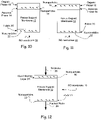
- 238000003917 TEM image Methods 0.000 description 1
- 229910052771 Terbium Inorganic materials 0.000 description 1
- ATJFFYVFTNAWJD-UHFFFAOYSA-N Tin Chemical compound [Sn] ATJFFYVFTNAWJD-UHFFFAOYSA-N 0.000 description 1
- RTAQQCXQSZGOHL-UHFFFAOYSA-N Titanium Chemical compound [Ti] RTAQQCXQSZGOHL-UHFFFAOYSA-N 0.000 description 1
- HCHKCACWOHOZIP-UHFFFAOYSA-N Zinc Chemical compound [Zn] HCHKCACWOHOZIP-UHFFFAOYSA-N 0.000 description 1
- QCWXUUIWCKQGHC-UHFFFAOYSA-N Zirconium Chemical compound [Zr] QCWXUUIWCKQGHC-UHFFFAOYSA-N 0.000 description 1
- NNLVGZFZQQXQNW-ADJNRHBOSA-N [(2r,3r,4s,5r,6s)-4,5-diacetyloxy-3-[(2s,3r,4s,5r,6r)-3,4,5-triacetyloxy-6-(acetyloxymethyl)oxan-2-yl]oxy-6-[(2r,3r,4s,5r,6s)-4,5,6-triacetyloxy-2-(acetyloxymethyl)oxan-3-yl]oxyoxan-2-yl]methyl acetate Chemical compound O([C@@H]1O[C@@H]([C@H]([C@H](OC(C)=O)[C@H]1OC(C)=O)O[C@H]1[C@@H]([C@@H](OC(C)=O)[C@H](OC(C)=O)[C@@H](COC(C)=O)O1)OC(C)=O)COC(=O)C)[C@@H]1[C@@H](COC(C)=O)O[C@@H](OC(C)=O)[C@H](OC(C)=O)[C@H]1OC(C)=O NNLVGZFZQQXQNW-ADJNRHBOSA-N 0.000 description 1
- FHKPLLOSJHHKNU-INIZCTEOSA-N [(3S)-3-[8-(1-ethyl-5-methylpyrazol-4-yl)-9-methylpurin-6-yl]oxypyrrolidin-1-yl]-(oxan-4-yl)methanone Chemical compound C(C)N1N=CC(=C1C)C=1N(C2=NC=NC(=C2N=1)O[C@@H]1CN(CC1)C(=O)C1CCOCC1)C FHKPLLOSJHHKNU-INIZCTEOSA-N 0.000 description 1
- XHCLAFWTIXFWPH-UHFFFAOYSA-N [O-2].[O-2].[O-2].[O-2].[O-2].[V+5].[V+5] Chemical compound [O-2].[O-2].[O-2].[O-2].[O-2].[V+5].[V+5] XHCLAFWTIXFWPH-UHFFFAOYSA-N 0.000 description 1
- 230000002730 additional effect Effects 0.000 description 1
- 230000002776 aggregation Effects 0.000 description 1
- 238000004220 aggregation Methods 0.000 description 1
- 125000001931 aliphatic group Chemical group 0.000 description 1
- 229910001420 alkaline earth metal ion Inorganic materials 0.000 description 1
- 230000004075 alteration Effects 0.000 description 1
- 229910001586 aluminite Inorganic materials 0.000 description 1
- PNEYBMLMFCGWSK-UHFFFAOYSA-N aluminium oxide Inorganic materials [O-2].[O-2].[O-2].[Al+3].[Al+3] PNEYBMLMFCGWSK-UHFFFAOYSA-N 0.000 description 1
- VCNTUJWBXWAWEJ-UHFFFAOYSA-J aluminum;sodium;dicarbonate Chemical compound [Na+].[Al+3].[O-]C([O-])=O.[O-]C([O-])=O VCNTUJWBXWAWEJ-UHFFFAOYSA-J 0.000 description 1
- HPTYUNKZVDYXLP-UHFFFAOYSA-N aluminum;trihydroxy(trihydroxysilyloxy)silane;hydrate Chemical compound O.[Al].[Al].O[Si](O)(O)O[Si](O)(O)O HPTYUNKZVDYXLP-UHFFFAOYSA-N 0.000 description 1
- 229910052934 alunite Inorganic materials 0.000 description 1
- 239000010424 alunite Substances 0.000 description 1
- 150000001408 amides Chemical class 0.000 description 1
- 230000000844 anti-bacterial effect Effects 0.000 description 1
- 230000003373 anti-fouling effect Effects 0.000 description 1
- 230000000845 anti-microbial effect Effects 0.000 description 1
- 238000013459 approach Methods 0.000 description 1
- 239000002152 aqueous-organic solution Substances 0.000 description 1
- 229910052785 arsenic Inorganic materials 0.000 description 1
- 238000003556 assay Methods 0.000 description 1
- 230000004888 barrier function Effects 0.000 description 1
- 229910001570 bauxite Inorganic materials 0.000 description 1
- 239000011324 bead Substances 0.000 description 1
- VXPZSDUXKPVHJC-UHFFFAOYSA-N benzene-1,2,3-tricarbonyl chloride Chemical compound ClC(=O)C1=CC=CC(C(Cl)=O)=C1C(Cl)=O VXPZSDUXKPVHJC-UHFFFAOYSA-N 0.000 description 1
- RPHKINMPYFJSCF-UHFFFAOYSA-N benzene-1,3,5-triamine Chemical compound NC1=CC(N)=CC(N)=C1 RPHKINMPYFJSCF-UHFFFAOYSA-N 0.000 description 1
- FDQSRULYDNDXQB-UHFFFAOYSA-N benzene-1,3-dicarbonyl chloride Chemical compound ClC(=O)C1=CC=CC(C(Cl)=O)=C1 FDQSRULYDNDXQB-UHFFFAOYSA-N 0.000 description 1
- 239000012620 biological material Substances 0.000 description 1
- 239000004305 biphenyl Chemical class 0.000 description 1
- 235000010290 biphenyl Nutrition 0.000 description 1
- 229910052797 bismuth Inorganic materials 0.000 description 1
- 229910001593 boehmite Inorganic materials 0.000 description 1
- 229910052796 boron Inorganic materials 0.000 description 1
- 125000000484 butyl group Chemical group [H]C([*])([H])C([H])([H])C([H])([H])C([H])([H])[H] 0.000 description 1
- VNSBYDPZHCQWNB-UHFFFAOYSA-N calcium;aluminum;dioxido(oxo)silane;sodium;hydrate Chemical compound O.[Na].[Al].[Ca+2].[O-][Si]([O-])=O VNSBYDPZHCQWNB-UHFFFAOYSA-N 0.000 description 1
- OYACROKNLOSFPA-UHFFFAOYSA-N calcium;dioxido(oxo)silane Chemical compound [Ca+2].[O-][Si]([O-])=O OYACROKNLOSFPA-UHFFFAOYSA-N 0.000 description 1
- 238000004364 calculation method Methods 0.000 description 1
- 239000011203 carbon fibre reinforced carbon Substances 0.000 description 1
- 239000011852 carbon nanoparticle Substances 0.000 description 1
- 239000007833 carbon precursor Substances 0.000 description 1
- 150000007942 carboxylates Chemical group 0.000 description 1
- 230000015556 catabolic process Effects 0.000 description 1
- 150000001768 cations Chemical class 0.000 description 1
- 230000030833 cell death Effects 0.000 description 1
- 210000002421 cell wall Anatomy 0.000 description 1
- 229920002301 cellulose acetate Polymers 0.000 description 1
- 238000005119 centrifugation Methods 0.000 description 1
- 239000002738 chelating agent Substances 0.000 description 1
- PBAYDYUZOSNJGU-UHFFFAOYSA-N chelidonic acid Natural products OC(=O)C1=CC(=O)C=C(C(O)=O)O1 PBAYDYUZOSNJGU-UHFFFAOYSA-N 0.000 description 1
- 238000010382 chemical cross-linking Methods 0.000 description 1
- 239000000460 chlorine Substances 0.000 description 1
- 229910052801 chlorine Inorganic materials 0.000 description 1
- 150000001805 chlorine compounds Chemical group 0.000 description 1
- 238000003776 cleavage reaction Methods 0.000 description 1
- 239000000084 colloidal system Substances 0.000 description 1
- 238000004891 communication Methods 0.000 description 1
- 238000010668 complexation reaction Methods 0.000 description 1
- 229910052593 corundum Inorganic materials 0.000 description 1
- 238000004132 cross linking Methods 0.000 description 1
- 239000003431 cross linking reagent Substances 0.000 description 1
- 229910001610 cryolite Inorganic materials 0.000 description 1
- 229910001647 dawsonite Inorganic materials 0.000 description 1
- 238000006731 degradation reaction Methods 0.000 description 1
- 230000000593 degrading effect Effects 0.000 description 1
- 239000002274 desiccant Substances 0.000 description 1
- 238000013461 design Methods 0.000 description 1
- GUJOJGAPFQRJSV-UHFFFAOYSA-N dialuminum;dioxosilane;oxygen(2-);hydrate Chemical compound O.[O-2].[O-2].[O-2].[Al+3].[Al+3].O=[Si]=O.O=[Si]=O.O=[Si]=O.O=[Si]=O GUJOJGAPFQRJSV-UHFFFAOYSA-N 0.000 description 1
- JYIMWRSJCRRYNK-UHFFFAOYSA-N dialuminum;disodium;oxygen(2-);silicon(4+);hydrate Chemical compound O.[O-2].[O-2].[O-2].[O-2].[O-2].[O-2].[Na+].[Na+].[Al+3].[Al+3].[Si+4] JYIMWRSJCRRYNK-UHFFFAOYSA-N 0.000 description 1
- GDVKFRBCXAPAQJ-UHFFFAOYSA-A dialuminum;hexamagnesium;carbonate;hexadecahydroxide Chemical compound [OH-].[OH-].[OH-].[OH-].[OH-].[OH-].[OH-].[OH-].[OH-].[OH-].[OH-].[OH-].[OH-].[OH-].[OH-].[OH-].[Mg+2].[Mg+2].[Mg+2].[Mg+2].[Mg+2].[Mg+2].[Al+3].[Al+3].[O-]C([O-])=O GDVKFRBCXAPAQJ-UHFFFAOYSA-A 0.000 description 1
- 229910001648 diaspore Inorganic materials 0.000 description 1
- 229910001649 dickite Inorganic materials 0.000 description 1
- 238000003618 dip coating Methods 0.000 description 1
- 238000009826 distribution Methods 0.000 description 1
- 230000001614 effect on membrane Effects 0.000 description 1
- 125000001495 ethyl group Chemical group [H]C([H])([H])C([H])([H])* 0.000 description 1
- 239000012527 feed solution Substances 0.000 description 1
- 229910001657 ferrierite group Inorganic materials 0.000 description 1
- 238000009292 forward osmosis Methods 0.000 description 1
- 229910003472 fullerene Inorganic materials 0.000 description 1
- 229910052733 gallium Inorganic materials 0.000 description 1
- 229910052732 germanium Inorganic materials 0.000 description 1
- 229910001679 gibbsite Inorganic materials 0.000 description 1
- PCHJSUWPFVWCPO-UHFFFAOYSA-N gold Chemical compound [Au] PCHJSUWPFVWCPO-UHFFFAOYSA-N 0.000 description 1
- 229910052737 gold Inorganic materials 0.000 description 1
- 239000010931 gold Substances 0.000 description 1
- 229910002804 graphite Inorganic materials 0.000 description 1
- 239000010439 graphite Substances 0.000 description 1
- 229910052621 halloysite Inorganic materials 0.000 description 1
- 238000013007 heat curing Methods 0.000 description 1
- 238000000265 homogenisation Methods 0.000 description 1
- 229920001477 hydrophilic polymer Polymers 0.000 description 1
- 230000005660 hydrophilic surface Effects 0.000 description 1
- 230000002706 hydrostatic effect Effects 0.000 description 1
- 229910001701 hydrotalcite Inorganic materials 0.000 description 1
- 229960001545 hydrotalcite Drugs 0.000 description 1
- FAHBNUUHRFUEAI-UHFFFAOYSA-M hydroxidooxidoaluminium Chemical compound O[Al]=O FAHBNUUHRFUEAI-UHFFFAOYSA-M 0.000 description 1
- 229910052900 illite Inorganic materials 0.000 description 1
- APFVFJFRJDLVQX-UHFFFAOYSA-N indium atom Chemical compound [In] APFVFJFRJDLVQX-UHFFFAOYSA-N 0.000 description 1
- PJXISJQVUVHSOJ-UHFFFAOYSA-N indium(III) oxide Inorganic materials [O-2].[O-2].[O-2].[In+3].[In+3] PJXISJQVUVHSOJ-UHFFFAOYSA-N 0.000 description 1
- 229910001387 inorganic aluminate Inorganic materials 0.000 description 1
- 229910052909 inorganic silicate Inorganic materials 0.000 description 1
- 238000002955 isolation Methods 0.000 description 1
- 229910001705 kalinite Inorganic materials 0.000 description 1
- NLYAJNPCOHFWQQ-UHFFFAOYSA-N kaolin Chemical compound O.O.O=[Al]O[Si](=O)O[Si](=O)O[Al]=O NLYAJNPCOHFWQQ-UHFFFAOYSA-N 0.000 description 1
- 229910052622 kaolinite Inorganic materials 0.000 description 1
- 238000000608 laser ablation Methods 0.000 description 1
- 238000013532 laser treatment Methods 0.000 description 1
- RVMQNIPAIQIBSC-UHFFFAOYSA-N lead;2,2,2-trifluoroacetic acid Chemical compound [Pb].OC(=O)C(F)(F)F RVMQNIPAIQIBSC-UHFFFAOYSA-N 0.000 description 1
- 229920002521 macromolecule Polymers 0.000 description 1
- 229910052748 manganese Inorganic materials 0.000 description 1
- 239000011572 manganese Substances 0.000 description 1
- 238000005259 measurement Methods 0.000 description 1
- 230000007246 mechanism Effects 0.000 description 1
- 230000001404 mediated effect Effects 0.000 description 1
- 229910001721 mellite Inorganic materials 0.000 description 1
- 239000012621 metal-organic framework Substances 0.000 description 1
- 150000002739 metals Chemical class 0.000 description 1
- 238000001471 micro-filtration Methods 0.000 description 1
- 239000011859 microparticle Substances 0.000 description 1
- 239000004941 mixed matrix membrane Substances 0.000 description 1
- 238000002156 mixing Methods 0.000 description 1
- 229910052961 molybdenite Inorganic materials 0.000 description 1
- CWQXQMHSOZUFJS-UHFFFAOYSA-N molybdenum disulfide Chemical compound S=[Mo]=S CWQXQMHSOZUFJS-UHFFFAOYSA-N 0.000 description 1
- 229910052982 molybdenum disulfide Inorganic materials 0.000 description 1
- 229910052901 montmorillonite Inorganic materials 0.000 description 1
- 229910052680 mordenite Inorganic materials 0.000 description 1
- 239000007783 nanoporous material Substances 0.000 description 1
- UFWIBTONFRDIAS-UHFFFAOYSA-N naphthalene-acid Natural products C1=CC=CC2=CC=CC=C21 UFWIBTONFRDIAS-UHFFFAOYSA-N 0.000 description 1
- 150000002790 naphthalenes Chemical class 0.000 description 1
- 229910001811 natroalunite Inorganic materials 0.000 description 1
- 230000007935 neutral effect Effects 0.000 description 1
- VGIBGUSAECPPNB-UHFFFAOYSA-L nonaaluminum;magnesium;tripotassium;1,3-dioxido-2,4,5-trioxa-1,3-disilabicyclo[1.1.1]pentane;iron(2+);oxygen(2-);fluoride;hydroxide Chemical compound [OH-].[O-2].[O-2].[O-2].[O-2].[O-2].[F-].[Mg+2].[Al+3].[Al+3].[Al+3].[Al+3].[Al+3].[Al+3].[Al+3].[Al+3].[Al+3].[K+].[K+].[K+].[Fe+2].O1[Si]2([O-])O[Si]1([O-])O2.O1[Si]2([O-])O[Si]1([O-])O2.O1[Si]2([O-])O[Si]1([O-])O2.O1[Si]2([O-])O[Si]1([O-])O2.O1[Si]2([O-])O[Si]1([O-])O2.O1[Si]2([O-])O[Si]1([O-])O2.O1[Si]2([O-])O[Si]1([O-])O2 VGIBGUSAECPPNB-UHFFFAOYSA-L 0.000 description 1
- 229910052755 nonmetal Inorganic materials 0.000 description 1
- 229910000273 nontronite Inorganic materials 0.000 description 1
- 238000000655 nuclear magnetic resonance spectrum Methods 0.000 description 1
- 239000012038 nucleophile Substances 0.000 description 1
- 150000002892 organic cations Chemical class 0.000 description 1
- 150000002902 organometallic compounds Chemical class 0.000 description 1
- 125000004430 oxygen atom Chemical group O* 0.000 description 1
- MKTRXTLKNXLULX-UHFFFAOYSA-P pentacalcium;dioxido(oxo)silane;hydron;tetrahydrate Chemical compound [H+].[H+].O.O.O.O.[Ca+2].[Ca+2].[Ca+2].[Ca+2].[Ca+2].[O-][Si]([O-])=O.[O-][Si]([O-])=O.[O-][Si]([O-])=O.[O-][Si]([O-])=O.[O-][Si]([O-])=O.[O-][Si]([O-])=O MKTRXTLKNXLULX-UHFFFAOYSA-P 0.000 description 1
- PPPLOTGLKDTASM-UHFFFAOYSA-A pentasodium;pentafluoroaluminum(2-);tetrafluoroalumanuide Chemical compound [F-].[F-].[F-].[F-].[F-].[F-].[F-].[F-].[F-].[F-].[F-].[F-].[F-].[F-].[Na+].[Na+].[Na+].[Na+].[Na+].[Al+3].[Al+3].[Al+3] PPPLOTGLKDTASM-UHFFFAOYSA-A 0.000 description 1
- 239000012466 permeate Substances 0.000 description 1
- 235000021317 phosphate Nutrition 0.000 description 1
- 150000003013 phosphoric acid derivatives Chemical class 0.000 description 1
- 229920002239 polyacrylonitrile Polymers 0.000 description 1
- 229920006393 polyether sulfone Polymers 0.000 description 1
- 229920005594 polymer fiber Polymers 0.000 description 1
- 229920005597 polymer membrane Polymers 0.000 description 1
- 229920001155 polypropylene Polymers 0.000 description 1
- 229920002451 polyvinyl alcohol Polymers 0.000 description 1
- 235000019422 polyvinyl alcohol Nutrition 0.000 description 1
- GNHOJBNSNUXZQA-UHFFFAOYSA-J potassium aluminium sulfate dodecahydrate Chemical compound O.O.O.O.O.O.O.O.O.O.O.O.[Al+3].[K+].[O-]S([O-])(=O)=O.[O-]S([O-])(=O)=O GNHOJBNSNUXZQA-UHFFFAOYSA-J 0.000 description 1
- 239000002244 precipitate Substances 0.000 description 1
- 238000001556 precipitation Methods 0.000 description 1
- 125000002924 primary amino group Chemical group [H]N([H])* 0.000 description 1
- 150000003142 primary aromatic amines Chemical class 0.000 description 1
- 125000001436 propyl group Chemical group [H]C([*])([H])C([H])([H])C([H])([H])[H] 0.000 description 1
- 230000005855 radiation Effects 0.000 description 1
- 229910052761 rare earth metal Inorganic materials 0.000 description 1
- 150000002910 rare earth metals Chemical class 0.000 description 1
- 238000010992 reflux Methods 0.000 description 1
- 230000003014 reinforcing effect Effects 0.000 description 1
- 229910000275 saponite Inorganic materials 0.000 description 1
- 230000007017 scission Effects 0.000 description 1
- 238000006748 scratching Methods 0.000 description 1
- 230000002393 scratching effect Effects 0.000 description 1
- 150000005619 secondary aliphatic amines Chemical class 0.000 description 1
- 125000000467 secondary amino group Chemical group [H]N([*:1])[*:2] 0.000 description 1
- 238000000926 separation method Methods 0.000 description 1
- 150000004760 silicates Chemical class 0.000 description 1
- 229910052710 silicon Inorganic materials 0.000 description 1
- 239000010703 silicon Substances 0.000 description 1
- 229910052709 silver Inorganic materials 0.000 description 1
- 239000004332 silver Substances 0.000 description 1
- 238000007764 slot die coating Methods 0.000 description 1
- SUKJFIGYRHOWBL-UHFFFAOYSA-N sodium hypochlorite Chemical compound [Na+].Cl[O-] SUKJFIGYRHOWBL-UHFFFAOYSA-N 0.000 description 1
- 239000007790 solid phase Substances 0.000 description 1
- 238000001179 sorption measurement Methods 0.000 description 1
- 239000000126 substance Substances 0.000 description 1
- 238000006467 substitution reaction Methods 0.000 description 1
- 239000000758 substrate Substances 0.000 description 1
- LXEJRKJRKIFVNY-UHFFFAOYSA-N terephthaloyl chloride Chemical compound ClC(=O)C1=CC=C(C(Cl)=O)C=C1 LXEJRKJRKIFVNY-UHFFFAOYSA-N 0.000 description 1
- PQDFWSNINWMLDU-UHFFFAOYSA-B tetraaluminum;decahydroxide;sulfate;pentahydrate Chemical compound O.O.O.O.O.[OH-].[OH-].[OH-].[OH-].[OH-].[OH-].[OH-].[OH-].[OH-].[OH-].[Al+3].[Al+3].[Al+3].[Al+3].[O-]S([O-])(=O)=O PQDFWSNINWMLDU-UHFFFAOYSA-B 0.000 description 1
- 125000003698 tetramethyl group Chemical group [H]C([H])([H])* 0.000 description 1
- 229910001770 thomsenolite Inorganic materials 0.000 description 1
- 230000001052 transient effect Effects 0.000 description 1
- 238000004627 transmission electron microscopy Methods 0.000 description 1
- KPZTWMNLAFDTGF-UHFFFAOYSA-D trialuminum;potassium;hexahydroxide;disulfate Chemical compound [OH-].[OH-].[OH-].[OH-].[OH-].[OH-].[Al+3].[Al+3].[Al+3].[K+].[O-]S([O-])(=O)=O.[O-]S([O-])(=O)=O KPZTWMNLAFDTGF-UHFFFAOYSA-D 0.000 description 1
- ITRNXVSDJBHYNJ-UHFFFAOYSA-N tungsten disulfide Chemical compound S=[W]=S ITRNXVSDJBHYNJ-UHFFFAOYSA-N 0.000 description 1
- 238000000108 ultra-filtration Methods 0.000 description 1
- 229910001935 vanadium oxide Inorganic materials 0.000 description 1
- 230000000007 visual effect Effects 0.000 description 1
- 229910001789 woodhouseite Inorganic materials 0.000 description 1
- 241000061450 x Ascocenda Species 0.000 description 1
- 229910001845 yogo sapphire Inorganic materials 0.000 description 1
- 229910052727 yttrium Inorganic materials 0.000 description 1
- 239000012690 zeolite precursor Substances 0.000 description 1
- XLOMVQKBTHCTTD-UHFFFAOYSA-N zinc oxide Inorganic materials [Zn]=O XLOMVQKBTHCTTD-UHFFFAOYSA-N 0.000 description 1
Images


Classifications
-
- B—PERFORMING OPERATIONS; TRANSPORTING
- B01—PHYSICAL OR CHEMICAL PROCESSES OR APPARATUS IN GENERAL
- B01D—SEPARATION
- B01D69/00—Semi-permeable membranes for separation processes or apparatus characterised by their form, structure or properties; Manufacturing processes specially adapted therefor
- B01D69/12—Composite membranes; Ultra-thin membranes
- B01D69/125—In situ manufacturing by polymerisation, polycondensation, cross-linking or chemical reaction
- B01D69/1251—In situ manufacturing by polymerisation, polycondensation, cross-linking or chemical reaction by interfacial polymerisation
-
- B—PERFORMING OPERATIONS; TRANSPORTING
- B01—PHYSICAL OR CHEMICAL PROCESSES OR APPARATUS IN GENERAL
- B01D—SEPARATION
- B01D69/00—Semi-permeable membranes for separation processes or apparatus characterised by their form, structure or properties; Manufacturing processes specially adapted therefor
- B01D69/12—Composite membranes; Ultra-thin membranes
- B01D69/125—In situ manufacturing by polymerisation, polycondensation, cross-linking or chemical reaction
-
- B—PERFORMING OPERATIONS; TRANSPORTING
- B01—PHYSICAL OR CHEMICAL PROCESSES OR APPARATUS IN GENERAL
- B01D—SEPARATION
- B01D61/00—Processes of separation using semi-permeable membranes, e.g. dialysis, osmosis or ultrafiltration; Apparatus, accessories or auxiliary operations specially adapted therefor
- B01D61/02—Reverse osmosis; Hyperfiltration ; Nanofiltration
- B01D61/025—Reverse osmosis; Hyperfiltration
-
- B—PERFORMING OPERATIONS; TRANSPORTING
- B01—PHYSICAL OR CHEMICAL PROCESSES OR APPARATUS IN GENERAL
- B01D—SEPARATION
- B01D67/00—Processes specially adapted for manufacturing semi-permeable membranes for separation processes or apparatus
- B01D67/0079—Manufacture of membranes comprising organic and inorganic components
- B01D67/00793—Dispersing a component, e.g. as particles or powder, in another component
-
- B—PERFORMING OPERATIONS; TRANSPORTING
- B01—PHYSICAL OR CHEMICAL PROCESSES OR APPARATUS IN GENERAL
- B01D—SEPARATION
- B01D69/00—Semi-permeable membranes for separation processes or apparatus characterised by their form, structure or properties; Manufacturing processes specially adapted therefor
- B01D69/10—Supported membranes; Membrane supports
-
- B—PERFORMING OPERATIONS; TRANSPORTING
- B01—PHYSICAL OR CHEMICAL PROCESSES OR APPARATUS IN GENERAL
- B01D—SEPARATION
- B01D69/00—Semi-permeable membranes for separation processes or apparatus characterised by their form, structure or properties; Manufacturing processes specially adapted therefor
- B01D69/14—Dynamic membranes
- B01D69/141—Heterogeneous membranes, e.g. containing dispersed material; Mixed matrix membranes
-
- B—PERFORMING OPERATIONS; TRANSPORTING
- B01—PHYSICAL OR CHEMICAL PROCESSES OR APPARATUS IN GENERAL
- B01D—SEPARATION
- B01D71/00—Semi-permeable membranes for separation processes or apparatus characterised by the material; Manufacturing processes specially adapted therefor
- B01D71/02—Inorganic material
- B01D71/0213—Silicon
-
- B—PERFORMING OPERATIONS; TRANSPORTING
- B01—PHYSICAL OR CHEMICAL PROCESSES OR APPARATUS IN GENERAL
- B01D—SEPARATION
- B01D71/00—Semi-permeable membranes for separation processes or apparatus characterised by the material; Manufacturing processes specially adapted therefor
- B01D71/02—Inorganic material
- B01D71/028—Molecular sieves
- B01D71/0281—Zeolites
-
- B—PERFORMING OPERATIONS; TRANSPORTING
- B01—PHYSICAL OR CHEMICAL PROCESSES OR APPARATUS IN GENERAL
- B01D—SEPARATION
- B01D2325/00—Details relating to properties of membranes
- B01D2325/48—Antimicrobial properties
-
- B—PERFORMING OPERATIONS; TRANSPORTING
- B01—PHYSICAL OR CHEMICAL PROCESSES OR APPARATUS IN GENERAL
- B01D—SEPARATION
- B01D71/00—Semi-permeable membranes for separation processes or apparatus characterised by the material; Manufacturing processes specially adapted therefor
- B01D71/02—Inorganic material
- B01D71/028—Molecular sieves
-
- B—PERFORMING OPERATIONS; TRANSPORTING
- B01—PHYSICAL OR CHEMICAL PROCESSES OR APPARATUS IN GENERAL
- B01D—SEPARATION
- B01D71/00—Semi-permeable membranes for separation processes or apparatus characterised by the material; Manufacturing processes specially adapted therefor
- B01D71/06—Organic material
- B01D71/56—Polyamides, e.g. polyester-amides
-
- Y—GENERAL TAGGING OF NEW TECHNOLOGICAL DEVELOPMENTS; GENERAL TAGGING OF CROSS-SECTIONAL TECHNOLOGIES SPANNING OVER SEVERAL SECTIONS OF THE IPC; TECHNICAL SUBJECTS COVERED BY FORMER USPC CROSS-REFERENCE ART COLLECTIONS [XRACs] AND DIGESTS
- Y02—TECHNOLOGIES OR APPLICATIONS FOR MITIGATION OR ADAPTATION AGAINST CLIMATE CHANGE
- Y02A—TECHNOLOGIES FOR ADAPTATION TO CLIMATE CHANGE
- Y02A20/00—Water conservation; Efficient water supply; Efficient water use
- Y02A20/124—Water desalination
- Y02A20/131—Reverse-osmosis
Definitions
- the present invention relates to an interfacial polymerization process for preparing a highly permeable RO-membrane, a reverse osmosis membrane prepared thereby and a method of purifying brackish water or sea water.
- Reverse osmosis membranes made by interfacial polymerization of a monomer in a nonpolar (e.g. organic) phase together with a monomer in a polar (e.g. aqueous) phase on a porous support membrane are known as TFC membranes and are used where flux and substantial rejection characteristics are required, for example in the purification of water.
- TFC membranes Various materials have been added to TFC membranes to increase flux without reducing rejection characteristics and have met with limited success.
- Such membranes are also subject to fouling resulting in reduced flux as contaminants, for example from the brackish or seawater to be purified, build up on the surface of the discrimination layer of the TFC membrane.
- WO01/78882 A2 discloses a polyamide membrane for reverse osmosis and is prepared by interfacial polymerization of m-phenylenediamine and trimesoyl chloride (TMC) on a porous support, with the TMC solution further comprising zeolite A nanoparticles.
- TMC trimesoyl chloride
- WO2006/098872 A2 discloses nanocomposite membranes and methods for making and using same.
- the nanocomposite membranes comprise a film comprising a polymer matrix and nanoparticles disposed within the polymer matrix, wherein the film is substantially permeable to water and substantially impermeable to impurities.
- the present invention provides an interfacial polymerization process for preparing a highly permeable RO-membrane comprising,
- the present invention also provides a reverse osmosis membrane prepared according to the process of the invention.
- the present invention also provides a method of purifying brackish water or sea water comprising contacting the brackish water or sea water with a reverse osmosis membrane according to the invention.
- RO membrane 10 is synthesized using a interfacial polymerization process on a porous support membrane 12. Two immiscible solvents are used, so that a monomer in one solvent reacts with a monomer in the other solvent. The reactions are very fast and relatively high molecular weights are obtained.
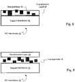
- fabric layer 20 may have nanoparticles 22 incorporated for added strength.
- Fabric layer 20 is preferably permeable to water, flat, and without stray fibers that could penetrate support 12 or thin film discrimination layer 24. It should be thin to decrease cost and to maximize membrane area, strong against extension, and mechanically resistant to deformation at high pressures. By adding nanoparticles 22 to the polymer fibers of fabric 20, more mechanically robust backings may be created that allow thinner, cheaper, and/or tougher supports to be manufactured.
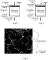
- aqueous phase layer 14 is shown with nanoparticles 16 dispersed therein on an upper surface of support membrane 12, and organic phase layer 18 interacts with aqueous layer 14.
- the interface between these layers is where the polymerization occurs.
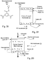
- Nanoparticles may be selected for their ability to release metal species such as alkaline earth or aluminum ions. Such particles may be dispersed within either the aqueous layer 14 or the organic phase layer 18, or both. Additional nanoparticles may also be present to impact surface properties or further increase performance, for example to improve fouling resistance. Nanoparticles 22 may be the same or different from nanoparticles 16. Metal ions 16 may be dissolved within either the aqueous layer 14, as shown in Fig. 10 , or the organic phase layer 18, as shown in Fig. 11 , or in both layers. Metal ions 16 may be dissolved within the aqueous layer 14, as shown in Fig. 13 .
- Nanoparticles 16 By dispersing aluminum releasing nanoparticles 16 in the aqueous or polar solvent 14 and/or organic phase layer 18 before interfacial polymerization, increased flux is often observed, especially when nanoparticles 16 are processed to enhance solubility of metal ions. Nanoparticles in solution may release aluminum before the polymerization reaction occurs to aqueous solution 14 or organic solution 18.
- the dissolved metal ions are thought to affect the polymerization reaction and ultimately membrane structure leading to improved performance. It is thought that the dissolved metal ions may serve as a template to guide polymerization leaving spaces or channels for increased water transport.
- nanoparticles 16 selected to release soluble metal species to introduce metal ions 17 into aqueous layer 14, during fabrication may be dispersed within or on porous support membrane 12. Nanoparticles 16 may also be introduced into aqueous layer 14 or organic phase layer 18 or both to introduce additional metal ions 17 into aqueous layer 14 during fabrication.
- Additional nanoparticles 17 may also be present to impact surface properties or further increase performance of membrane 10
- the interfacial polymerization process at least one of solutions a) and b) contains nanoparticles that release at least 1 ppm of a soluble metal species per 5% (w/w) nanoparticles, based on the weight of the mixture, and wherein said nanoparticles have been processed to maximize the amount of said soluble metal species contributed to the interfacial polymerization mixture.
- RO membranes may be fabricated in which nanoparticles are included in the porous support membrane to release soluble metal ions for the interfacial polymerization process and/or improve flux flow decline by, perhaps, resisting compaction of the support membranes during reverse osmosis.
- the nanoparticles may be selected based on their ability to release 1 ppm or more of soluble metal species into the water contained in the support membrane. It may be advantageous to store the support membrane, for example for up to one hour, before interfacial polymerization on the support membrane between aqueous and organic phase solutions. It may also be advantageous to form the discrimination layer by contacting the aqueous phase solution to the organic phase solution on the support membrane for at least 10 seconds, preferably 2 minutes and more preferably 5 minutes after the organic phase solution is applied.
- Membrane 12 is typically a polymeric microporous support membrane which in turn is often supported by nonwoven or woven fabrics, such as fabric 20, for mechanical strength.
- Support membranes 12 are typically 25-250 microns in thickness and have been found to have the smallest pores located very near the upper surface. Porosity at the surface is often low, for instance from 5-15%, of the total surface area.
- Nanoparticles 16 may be incorporated into support membrane 12 by including nanoparticles 16 with casting solution 13 used to prepare support membrane 12, or by including nanoparticles 16 within the nonsolvent, e.g. DI water, used to induce phase inversion during fabrication of support membrane 12.
- nonsolvent e.g. DI water
- the addition of nanoparticles 16 to support membrane 12 may also serve to increase or maintain flux, or at least reduce the decline over time of the flux, of purified water 28 through membrane 10 from reverse osmosis of saltwater 26.
- the application of hydrostatic pressures via saltwater 26 to conventional thin film composite membranes (TFC) is known to cause a reduction of membrane permeability, probably due to compaction of support membrane 12.
- TFC thin film composite membranes
- Nanoparticles in solution in aqueous solution 14 or organic solution 18 may release metal ions 17 before the polymerization.
- Dissolved metal ions 17 are thought to affect the polymerization reaction and ultimately membrane structure leading to improved performance. It is thought that the dissolved metal ions 17 may serve as a template to guide polymerization leaving spaces or channels for increased water transport.
- porous support membrane 12 including nanoparticles 16 dispersed therein, and/or on the surface thereof can be immersed in an aqueous solution, such as aqueous phase 14, containing a first reactant (e.g., 1,3-diaminobenzene or "MPD" monomer) to release soluble metal ions 17 therein.
- a first reactant e.g., 1,3-diaminobenzene or "MPD" monomer
- Support membrane 12 can then be put in contact with an organic solution, such as organic phase 18, containing a second reactant (trimesoyl chloride or "TMC" initiator).
- TMC trimesoyl chloride
- the organic or apolar liquid is immiscible with the polar or aqueous liquid, so that the reaction occurs at the interface between the two solutions, e.g. between aqueous and organic phases 14,18 to form a dense polymer layer on surface of support membrane 12.
- Suitable nanoparticles 16 for dispersion in support membrane 12 as described above include those selected for their ability to release alkaline earth metals, or other metal species, into organic phase 14 during the interfacial polymerization reaction, especially when nanoparticles 16 are processed to enhance solubility of metal ions such as alkaline earth metals 17.
- Nanoparticles 16 may be selected to release metal ions 17 which may enter the water or other solvent contained within or on support membrane 12.
- the amount of metal ions 17 available for the interfacial polymerization of aqueous phase 14 and organic phase 18 may in some cases be increased by storing support membrane 12, for example in roll form, for a suitable time period such as at least one hour before fabrication of RO membrane 10.
- metal ions 17 may be important to allow sufficient time for metal ions 17 to diffuse from support membrane 12 into aqueous phase 14 before or during interfacial polymerization.
- a time of between 2 seconds and 5 minutes, and preferably between 10 seconds and 2 minutes is currently believed to be suitable for such diffusion so that metal ions 17 from nanoparticles 16 impacts formation of discrimination layer 24 and improves performance of RO membrane for example by increasing water flux therethrough for the same applied pressure.
- Sonication processing nanoparticles 16 may include immersing a sonic probe directly into casting solution 13 from which support membrane 12 is formed or into organic or aqueous phases 14 and/or 18 and/or placing solutions with nanoparticles 16 in a vessel and immersing the vessel in a sonic bath. Solutions are subjected to sufficient sonic energy from 10 to 60 minutes to aid in the release of metal species, such as alkaline earth metal ions 17, into the solution. After sonication, the solution contains additional metal species. Additional sonication time may release additional metal species up to some limit equilibrium.
- Processing of selected nanoparticles 16 may also be accomplished using shear, cavitation, and impact forces generated by 1 to 60 minutes in a Microfluidizer (a trademark of the Microfluidics Corp.). After processing, the solution contains additional metal species that were dissolved from nanoparticles 16.
- Processing of selected nanoparticles 16 may be also accomplished using a solution containing nanoparticles 16 in a vessel with a stir bar and using a stir plate to propel the stir bar in the solution or alternatively using a motorized propeller to stir the solution or alternatively using a lab tray shaker. Stirring or shaking is most effective for nanoparticles that have been selected for high solubility in either the aqueous or the organic phases 14, 18.
- Processing of the selected nanoparticles 16 may be accomplished using a solution containing nanoparticles 16 in a vessel and adjusting the pH either lower than about 6 and more preferably less than about 5 for at least 30 seconds, to a pH greater than about 8 and more preferably greater than about 9 for at least 30 seconds. Whether pH is adjusted higher than about 8 or lower than about 6 may dependent on the solubility characteristics of the specific type of nanoparticle 16.
- molecular additive encompasses mHTMC.
- preferred concentrations of molecular additives are from 0.0001% (weight percent equivalent of 1 ppm) to 5% by weight and more preferred from 0.05% to 1 % into aqueous layer 14.
- Processing may enhance nanoparticle dissolution, or other techniques for adding molecular additives to assist in achieving the desired concentrations of molecular additives 17 in solution.
- Processed nanoparticles or other carries may have been broken or partially dissolved using shear, cavitation, or impact forces to maximize said soluble metal species contributed to the interfacial polymerization mixture, including a microfluidizer apparatus.
- the nanoparticles or other relatively insoluble carriers may have been calcined for at least 1 hour at 200°C or more.
- the processed carriers can have been shaken in aqueous solution on a shaker table for at least 1 minute.
- Carriers may have been processed by subjecting them to sonic energy in a vessel having a sonic probe within a solution, said energy sufficient to increase the soluble metal species or other molecular additives contributed by the processed carriers to the interfacial polymerization mixture, e.g., in a vessel suspended in a sonic bath for at least 5 minutes.
- the nanoparticles or other relatively insoluble carriers may have been processed in a solution at a pH lower than about 6 for at least 30 seconds or at a pH lower than about 5 for at least 30 seconds.
- the nanoparticles or other relatively insoluble carriers may have been processed in a solution at a pH greater than about 8 for at least 30 seconds or in a solution at a pH greater than about 9 for at least 30 seconds.
- Nanoparticles or other relatively insoluble carriers may have been processed with heat in a solution for at least 5 minutes at a temperature of 40 °C or more.
- Nanoparticles or other relatively insoluble carriers may have been processed with chelating agents in solution to bind soluble metal species or other molecular additives.
- Zeolites and other inorganic mineral compounds may also be further selected for use as nanoparticles 16 to release molecular additives 17 based on the degree of crystallization the nanoparticles 16.
- Amorphous portions of nanoparticles 16 are typically more soluble than crystalline portions of the nanoparticle and processing can increase solubility.
- the amount of crystalline material can be determined through several techniques including x-ray crystallography.
- nanoparticles or other insoluble carriers 16 may be included in organic phase or layer 18, both aqueous layer 14 and organic layer 18, and/or also or only in a layer between aqueous phase 14 and support membrane 12 for example in water solution 15 in liquid communication with both aqueous layer 14 and the water wetted surface of support membrane 12. Nanoparticles or other relatively insoluble carriers 16 may in fact be in the water wetted surface of support membrane 12 whether or not included in the aqueous layer 14 or organic layer 18.
- Support membrane 12 is typically a polymeric microporous support membrane, which in turn is often supported by non-woven or woven fabrics, such as fabric 20, for mechanical strength.
- Support membrane 12 may conventionally be made from polysulfone or other suitably porous membranes, such as polyethersulfone, poly(ether sulfone ketone), poly(ether ethyl ketone), poly(phthalazinone ether sulfone ketone), polyacrylonitrile, polypropylene, cellulose acetate, cellulose diacetate, or cellulose triacetate.
- These microporous support membranes 12 are typically 25-250 microns in thickness and may have the smallest pores located very near the upper surface. Porosity at the surface may be low, for instance from 5-15% of the total surface area.
- the preparation of support membrane 12 may begin with the addition of N-methyl pyrrolidone (NMP) solvent (Acros Organics, USA) to a polysulfone polymer (M,-26,000 from Aldrich, USA) in transparent bead form in airtight glass bottles.
- NMP N-methyl pyrrolidone
- M polysulfone polymer
- DMF dimethylformamide
- Nanoparticles 16 may be dispersed in the NMP before its addition to the polysulfone polymer.
- the solution may then be agitated for several hours until complete dissolution is achieved, forming the dope or casting solution 13.
- Casting solution 13 may then be cast or spread over non-woven fabric 20 attached to glass plate 15 via a knife-edge.
- Glass plate 15 may then be immediately immersed into demineralized water, which had preferably been maintained at the desired temperature. Immediately, phase inversion begins and after several minutes, non-woven support fabric 20 supporting polysulfone membrane 12 may be separated from glass plate 15. Membrane 12 is then washed thoroughly with deionized water and stored in cold conditions until used. In a continuous coating process, glass plate 15 would not be required.
- Nanoparticles such as zeolites, particularly LTA may be added to support membrane 12 during processing to improve flux for reverse osmosis by, perhaps, improving porosity e.g. at the surface of support membrane 12 and/or by making membrane 12 more resistant to compaction.
- nanoparticles or other relatively insoluble carriers 16 may be added to aqueous phase 14 to improve RO membrane characteristics such as flux without reducing rejection as much as adding nanoparticles 16 to the organic phase 18. Nanoparticles or other relatively insoluble carriers 16 may similarly be included in a layer between support membrane 12 and discrimination layer 24 as shown below in Fig. 6 .
- the rejection may be at least 99.5% and the flux at least 11580, 13510, or 15440 liter per square meter per day (LMD) (30, 35 or 40 GFD).
- Nanoparticles or other relatively insoluble carriers 16 may include a metallic species such as gold, silver, copper, zinc, titanium, iron, aluminum, zirconium, indium, tin, magnesium, or calcium or an alloy thereof or an oxide thereof or a mixture thereof. They can also be a nonmetallic species such as Si 3 N 4 , SiC, BN, B 4 C, or TiC or an alloy thereof or a mixture thereof. They can be a carbon-based species such as graphite, carbon glass, a carbon cluster of at least C 2 , buckminsterfullerene, a higher fullerene, a carbon nanotube, a carbon nanoparticle, or a mixture thereof.
- a metallic species such as gold, silver, copper, zinc, titanium, iron, aluminum, zirconium, indium, tin, magnesium, or calcium or an alloy thereof or an oxide thereof or a mixture thereof. They can also be a nonmetallic species such as Si 3 N 4 , SiC, BN, B 4 C, or TiC or an
- Suitable zeolites for use as nanoparticles 16 include LTA, RHO, PAU, and KFI. Such synthetic zeolites have different Si/Al ratios, and exhibit different characteristic charge and hydrophilicity and may therefore be selected for RO membranes 10 in different circumstances. Nanoparticles 16 may also include zeolite precursors or amorphous aluminosilicates.
- Zeolites can be crystalline aluminosilicates with fully cross-linked, open framework structures made up of corner-sharing SiO 4 and AlO 4 tetrahedra.
- a representative empirical formula of a zeolite is M 2/n O ⁇ Al 2 O 3 ⁇ xSiO 2 ⁇ yH 2 O where M represents the exchangeable cation of valence n.
- M is generally a Group I or II ion, although other metal, non-metal, and organic cations can also balance the negative charge created by the presence of Al in the structure.
- the framework can contain interconnected cages and channels of discrete size, which can be occupied by water. in addition to Si 4+ and Al 3+ , other elements can also be present in the zeolitic framework.
- Aluminosilicate zeolites typically display a net negative framework charge, but other molecular sieve frameworks can be electrically neutral.
- Aluminosilicate zeolites with a Si:Al ratio less than 1.5:1 are preferred.
- Other preferred minerals include Aluminite, Alunite, Ammonia Alum, Anauxite, Apjohnite, Basaluminite, Batavite, Bauxite, Mitrikalite, Boehmite, Cadwaladerite, Cardenite, Chalcoalumite, Chiolite, Chloraluminite, Cryolite, Dawsonite, Diaspore, Dickite, Gearksutite, Gibbsite, Halloysite, Hydrobasaluminite, Hydrocalumite, Hydrotalcite, Illite, Kalinite, Kaolinite, Mellite, Montmorillonite, Natroalunite, Nontronite, Pachnolite, Prehnite, Prosopite, Ralstonite, Ransomite, Saponite, Thomsenolite, Weberite, Woodhouseite, and Zincaluminite.
- Zeolites and other inorganic mineral compounds may also be further selected based on the degree of crystallization.
- Amorphous portions of the nanoparticle are typically more soluble than crystalline portions of the nanoparticle and processing can increase solubility.
- the amount of crystalline material can be determined through several techniques including x-ray crystallography.
- the nanoparticles may have a structure with greater than 0.5%, 1% or 5% amorphous material by mass within the particle and may have a surface containing at least 40% of aluminum atoms or oxygen atoms directly bound to aluminum atoms.
- Mminerals that have similar cage-like framework structures to Zeolites or have similar properties and/or are associated with zeolites include the phosphates: kehoeite, pahasapaite and tiptopite; and the silicates: hsianghualite, Iovdarite, viseite, partheite, prehnite, roggianite, apophyllite, gyrolite, maricopaite, okenite, tacharanite and tobermorite.
- minerals similar to zeolites may also be molecular sieves based on AlPO 4 .
- AlPO 4-n aluminophosphate
- SAPO-n aluminophosphate
- MeAPO-n aluminophosphate
- MeAPSO-n metallosilicoaluminophosphates
- AlPO 4 molecular sieves can have the structure of known zeolites or other structures.
- Si is incorporated in an AlPO 4-n framework
- the product can be known as SAPO.
- MeAPO or MeAPSO sieves are can be formed by the incorporation of a metal atom (Me) into an AlPO 4-n or SAPO framework.
- metal atoms include Li, Be, Mg, Co, Fe, Mn, Zn, B, Ga, Fe, Ge, Ti, and As.
- AlPO 4-n Most substituted AlPO 4-n 's have the same structure as AlPO 4- n , but several new structures are only found in SAPO, MeAPO and MeAPSO materials. Their frameworks typically carry an electric charge.
- Non-zeolite nanoparticles and or other relatively insoluble carriers may be selected from a list of inorganic mineral compounds that have a solubility product such that preferred concentrations of dissolved molecular addtives can be achieved.
- these solubility products Ksp
- molecular additive releasing or other relatively insoluble carriers may also be selectable by their counter ion. In such cases, compounds may be selected based on the presence of sulfate, hydroxide or oxide counterions. Solubility of these non-zeolite nanoparticles or other relatively insoluble carriers can be enhanced using processing.
- Particle size is often described in terms of average hydrodynamic diameter, assuming a spherical shape of the particles or other relatively insoluble carriers.
- Selected nanoparticle or other relatively insoluble carriers 16 can have an average hydrodynamic diameter of from about 0.1 nm to about 1000 nm, from about 10 nm to about 1000 nm, from about 20 nm to about 1000 nm, from about 50 nm to about 1000 nm, from about 0.11 nm to about 500 nm, from about 10 nm to about 500 nm, from about 50 nm to about 250 nm, from about 200 nm to about 300 nm, or from about 50 nm to about 500 nm.
- Suitable nanoparticles or other relatively insoluble carriers are often dispersed in a solution compatible with the aqueous or polar solvent that will be used during interfacial polymerization.
- This dispersion largely includes isolated and individual nanoparticles or other relatively insoluble carriers.
- Suitable methods for dispersion include stirring, ultrasonication, shaking, use of surfactants or cosolvents, use of Microfluidizer TM (a trademark of the Microfluidics Corp.) material or similar materials, use of mortar and pestle, use of a ball mill or jar mill.
- some of the nanoparticles or other relatively insoluble carriers may still be associated with other nanoparticles or other relatively insoluble carriers. These aggregates may be left in solution, or removed by a suitable technique.
- TFC membranes including nanoparticles or other relatively insoluble carriers having improved performance can be obtained.
- increased flux is often observed with TFC membranes prepared with solutions containing well dispersed nanoparticles or other relatively insoluble carriers.
- suitable (e.g. having optimized size, shape, porosity, and/or surface chemistry) nanoparticles or other relatively insoluble carriers in the aqueous solution or organic solution, followed by appropriate preparation techniques can lead to such well dispersed solutions of nanoparticle or other relatively insoluble carriers.
- films with a high number of nanoparticles or other relatively insoluble carriers incorporated in the final membrane can be prepared.
- nanoparticles or other relatively insoluble carriers 16 can exist either as isolated and individual species or as building blocks incorporated in larger aggregate structures. These structures can be fairly stable and unchanging such as those formed during synthesis (for instance during calcinations of zeolites) or they can be transient structures arising from thermodynamics of the carriers and solution.
- Well dispersed solutions that is solutions in which the nanoparticles or other relatively insoluble carriers are well dispersed, primarily contain isolated and individual nanoparticles or other relatively insoluble carriers rather than aggregates of such particles.
- Solutions in which nanoparticles or other relatively insoluble carriers are well dispersed, without substantial aggregates, can be attained by the use, for example of nanoparticles of zeolite LTA in the aqueous or polar solvent 14 that will be used during interfacial polymerization.
- aqueous or polar solvent 14 that will be used during interfacial polymerization.
- water is used as both the dispersion solvent and the aqueous solvent for use during the reaction.
- This dispersion largely has isolated and individual nanoparticles.
- This particular solution is well dispersed due to the hydrophilic surface of LTA and its strong interaction with water, its small size of less than 1 micron.
- Suitable methods for causing the desired dispersion include stirring, ultrasonication, shaking, use of surfactants or cosolvents, use of a Microfluidizer TM type material, use of mortar and pestle, use of a ball mill or jar mill.
- high intensity ultrasonication or the Microfluidizer performed for a sufficient time period results in well dispersed solutions.
- aqueous phase 14 used during interfacial polymerization may also include one of the reactants, nanoparticles, or other relatively insoluble carriers, and processing aids such as surfactants, drying agents, catalysts, coreactants, cosolvents, etc.
- the polymer matrix which forms discrimination layer 24 can be prepared by reaction of two or more monomers.
- the first monomer can be a dinucleophilic or a polynucleophilic monomer and the second monomer can be a dielectrophilic or a polyelectrophilic monomer. That is, each monomer can have two or more reactive (e.g., nucleophilic or electrophilic) groups. Both nucleophiles and electrophiles are well known in the art, and one of skill in the art can select suitable monomers for this use.
- the first and second monomers can also be chosen so as to be capable of undergoing an interfacial polymerization reaction to form a polymer matrix (i.e., a three-dimensional polymer network) when brought into contact.
- the first and second monomers can also be chosen so as to be capable of undergoing a polymerization reaction when brought into contact to form a polymer product that is capable of subsequent crosslinking by, for example, exposure to heat, light radiation, or a chemical crosslinking agent.
- the first monomer can be selected so as to be soluble in a polar liquid, preferably water, to form a polar mixture.
- the difunctional or polyfunctional nucleophilic monomer can have primary or secondary amino groups and can be aromatic (e.g., a diaminobenzene, a triaminobenzene, m-phenylenediamine, p-phenyenediamine, 1,3,5-triaminobenzene, 1,3,4-triaminobenzene, 3,5-diaminobenzoic acid, 2,4-diaminotoluene, 2,4-diaminoanisole, and xylylenediamine) or aliphatic (e.g., ethylenediamine, propylenediamine, piperazine, and tris(2-diaminoethyl)amine).
- the polar liquid and the first monomer can be the same compound; that is, the first monomer can provided and not dissolved in
- Suitable amine species include primary aromatic amines having two or three amino groups, for example m-phenylene diamine, and secondary aliphatic amines having two amino groups, for example piperazine.
- the amine can typically be applied to the microporous support as a solution in a polar liquid, for example water.
- the resulting polar mixture typically includes from about 0.1 to about 20 weight percent, preferably from about 0.5 to about 6 weight percent, amine. Once coated on a porous support, excess polar mixture can be optionally removed.
- the polar mixture need not be aqueous, but the polar liquid should be immiscible with the apolar liquid.
- water is a preferred solvent
- non-aqueous polar solvents can be utilized, such as acetonitrile and dimethylformamide (DMF).
- the polar mixture can typically be applied to microporous support membrane 12 by dipping, immersing, coating or other well known techniques. Once coated on porous support membrane 12, excess polar mixture can be optionally removed by evaporation, drainage, air knife, rubber wiper blade, nip roller, sponge, or other devices or processes.
- Organic phase 18 used during interfacial polymerization may also include one of the reactants, nanoparticles, or other relatively insoluble carriers, and processing aids such as catalysts, co-reactants, co-solvents, etc.
- the second monomer contains trimesoyl chloride as a polyfunctional acid halide monomer.
- Suitable polyfunctional acyl halides include trimesoyl chloride (TMC), trimellitic acid chloride, isophthaloyl chloride, terephthaloyl chloride and similar compounds or blends of suitable acyl halides.
- TMC trimesoyl chloride
- trimellitic acid chloride trimellitic acid chloride
- isophthaloyl chloride trimellitic acid chloride
- terephthaloyl chloride trimellitic acid chloride
- the second monomer can be a phthaloyl halide.
- the polyfunctional acyl halide can be dissolved in the apolar organic liquid in a range of, for example, from about 0.01 to about 10.0 weight percent or from about 0.05 to about 3 weight percent.
- Suitable apolar liquids are capable of dissolving the electrophilic monomers (e.g. polyfunctional acyl halides) and which are immiscible with a polar liquid (e.g., water).
- suitable apolar liquids can include those which do not pose a threat to the ozone layer and yet are sufficiently safe in terms of their flashpoints and flammability to undergo routine processing without having to undertake extreme precautions.
- C 5 - C 7 hydrocarbons and higher boiling hydrocarbons include C 5 - C 7 hydrocarbons and higher boiling hydrocarbons, i.e., those with boiling points greater than about 90 °C, such as C 8 - C 24 hydrocarbons and mixtures thereof, which have more suitable flashpoints than their C 5 - C 7 counterparts, but are less volatile.
- the apolar mixture can typically be applied to the microporous support membrane 12 by dipping, immersing, coating or other well known techniques.
- the polyfunctional acyl halide monomer (also referred to as acid halide) is coated on support membrane 12, typically from organic phase solution 18.
- Amine solution 14 is typically coated first on porous support 12 followed by acyl halide solution 18.
- the monomers can react when in contact, thereby polymerizing to produce a polymer (e.g., polyamide) matrix film discrimination layer 24 at the upper surface of support structure 12.
- a polymer e.g., polyamide
- one or both of the polyfunctional amine and acyl halide layers can be applied to porous support 12 from a solution, such as aqueous and organic solutions 14 and 18, they can alternatively be applied by other means such as by vapor deposition, or heat.
- Suitable earth alkaline metal species or other molecular additives 16 include salts or compounds that are dissolvable to some extent in either the aqueous phase layer 14 or the organic phase layer 18 or both. Different species may be used for the aqueous phase layer 14 and the organic phase layer 18. In many embodiments the beta-diketonate may be an acetoacetonate.
- Preferred species in the organic phase for aluminum species include Al(acac) 3 , wherein (acac) is acetylacetonate, a bidentate ligand.
- Preferred species in the aqueous layer include sodium aluminate, aluminum citrate, and aluminum camphorsulfonate.
- Preferred species for other molecular additives including alkaline earth metals are set forth in Tables I-XII herein below.
- Preferred concentrations of the metal species are from 0.005 wt.% to 5 wt.% by weight and more preferred from 0.05 wt.% to 1 wt.% in either aqueous layer 14 or organic layer 18.
- Sonication may serve to better disperse the molecular species. Sonication may also serve to drive reactions that would otherwise require higher temperatures, catalysts, or initiators to occur.
- performance can be further improved by the addition of a rinse in a high pH aqueous solution after RO membrane 10 is formed.
- membrane 10 can be rinsed in a sodium carbonate solution.
- the pH is preferably from 8-12, and exposure time may vary from 10 seconds to 30 minutes or more.
- the rinse may alternatively be a hot water rinse with temperatures of 60-98C.
- the rinse may also include a chlorine species such as sodium hypochlorite.
- Discrimination layer 24 may typically be a composite polyamide membrane prepared by coating porous support membrane 12 with a polyfunctional amine monomer, most commonly coated from aqueous phase solution 14.
- a polyfunctional amine monomer most commonly coated from aqueous phase solution 14.
- non-aqueous solvents can be utilized, such as acetonitrile and dimethylformamide (DMF).
- a polyfunctional acyl halide monomer (also referred to as acid halide) may then subsequently be coated on support membrane 12, typically from organic phase solution 18.
- the amine solution 14 is typically coated first on 12 porous support followed by acyl halide solution 18.
- the monomers can react when in contact, thereby polymerizing to produce a polymer (e.g., polyamide) matrix film 24 at the upper surface of support structure 12.
- a polymer e.g., polyamide
- one or both of the polyfunctional amine and acyl halide can be applied to porous support 12 from a solution, such as aqueous and organic solutions 14 and 18, they can alternatively be applied by other means such as by vapor deposition, or heat.
- Nanoparticles and other relatively insoluble carriers in solution may release molecular additives before the polymerization reaction occurs to the aqueous solution 14 or organic solution 18.
- the dissolved molecular additive is thought to affect the polymerization reaction and ultimately membrane structure leading to improved performance. It is thought that the dissolved molecular additive may serve as a template to guide polymerization leaving spaces or channels for increased water transport.
- Suitable nanoparticles or other relatively insoluble carriers for dispersion include those selected for their ability to release the desired molecular additives in either the organic phase or the aqueous phase of an interfacial polymerization reaction.
- the solubility constant may be considered to be the mass of molecular additive in solution (e.g. additive 17) divided by the initially used mass of nanoparticle or other carrier in the same solution. For example, a 5 wt% solution of nanoparticle that gives 1 ppm of dissolved metal species would give a 0.002% solubility constant, and a 1% solution giving 1 ppm give 0.01%. Solubility of minerals can be used as a general guide to the solubility of those same mineral nanoparticles.
- nanoparticles have greater surface exposure per unit mass and smaller nanoparticles increase the number of exposed metal or other atoms per unit area over and above a simple surface area effect. Greater exposure of such atoms or molecules in solution may increase solubility of the desired additives. Presence of counter ions such as sulfate, hydroxide and fluoride may also increase solubility.
- Calcined zeolite nanoparticles may increase additive solubility because the calcining process may increase the amount of additive in pores and hence available for exchange.
- Zeolites and other inorganic mineral compounds can be further selected based on the degree of crystallization. Amorphous portions of the nanoparticle are more soluble than crystalline portions of the nanoparticle. The amount of crystalline material can be determined through several techniques including x-ray crystallography.
- Non-zeolite nanoparticles may be selected from a list of inorganic mineral compounds that have a solubility product such that preferred concentrations of dissolved metal species or other additives can be achieved. For many compounds these solubility products (Ksp) are well known. For compounds where these are not known experimentally, additive releasing nanoparticles can also be selected by their counter ion. In this case compounds are selected based on the presence of sulfate, hydroxide or oxide counter ions.
- Preferred concentrations of the additives dissolved from nanoparticles are from 0.0001% to 5% by weight, and more preferred from 0.05 wt.% to 1 wt.% in either aqueous layer 14 or organic layer 18.
- Non-zeolite hydrocarbon nanoparticles can be selected based on the presence of the desired additive in the ash of these hydrocarbons.
- the presence of the additive in the ash of these compounds may relate to the ability of these compounds to release the additive in solution.
- These hydrocarbon nanoparticles are preferably included in the organic phase 18.
- Sonication may serve to better disperse the nanoparticles. Sonication may also serve to drive reactions that would otherwise require higher temperatures, catalysts, or initiators to occur.
- the porous support structure can be immersed in an aqueous solution containing a first reactant (e.g., 1,3-diaminobenzene or "MPD" monomer).
- a first reactant e.g., 1,3-diaminobenzene or "MPD” monomer
- the substrate can then be put in contact with an organic solution containing a second reactant (trimesoyl chloride or "TMC” monomer).
- TMC trimesoyl chloride
- the organic or apolar liquid is immiscible with the polar or aqueous liquid, so that the reaction occurs at the interface between the two solutions to form a dense polymer layer on the support membrane surface.
- Representative conditions for reaction of an amine (e.g., MPD) with an electrophile (e.g., TMC) to form a polyamide thin film composite membrane employ a concentration ratio of MPD to TMC of about 10 - 20, with the MPD concentration being about 1 to 6 weight percent of the polar phase (aqueous phase 14).
- the polymerization reaction can be carried out at room temperature in an open environment, or the temperature of either the polar or the apolar liquid, or both, may be controlled.
- the dense polymer layer, which becomes discrimination layer 24 can advantageously act as a barrier to inhibit contact between the reactants and to slow the reaction.
- a selective dense layer is formed which is typically very thin and permeable to water, but relatively impermeable to dissolved, dispersed, or suspended solids, such as salts to be removed from saltwater or brackish water in use to produce purified water.
- This type of membrane is conventionally described as a reverse osmosis (RO) membrane.
- the apolar liquid can be removed by evaporation or mechanical removal. It is often convenient to remove the apolar liquid by evaporation at elevated temperatures, for instance in a drying oven.
- performance can be further improved by the addition of a rinse step using a high pH aqueous solution after RO membrane 10 is formed.
- membrane 10 can be rinsed in a sodium carbonate solution.
- the pH is preferably from 8-12, and exposure time may vary from 10 seconds to 30 minutes or more.
- saltwater 26 when used for saltwater purification, saltwater 26 may be applied under pressure to discrimination layer 24 including nanoparticles 16. Purified water 28 then passes through porous support membrane 12 and fabric layer 20 if present.
- nanoparticles 16 may also, or only, be present between discrimination layer 24 and the top surface of support membrane 12.
- nanoparticles can be included within membranes for several reasons, for instance to increase permeability, to alter surface chemistry, to alter roughness or morphology, or to enable anti-bacterial activity and particularly to reduce fouling especially in the presence of other molecular additives.
- the percent of the surface of RO membrane 10 containing nanoparticles 16 can be measured by any suitable technique.
- this incorporation can effectively be measured by isolating the thin film of discrimination layer 24 and using transmission electron microscopy (TEM) to measure the percentage of the membrane containing nanoparticles.
- TEM transmission electron microscopy
- membranes with more than 5 wt.%, 10 wt.% or even 20 wt.% incorporation of nanoparticle zeolite LTA can be prepared. In some embodiments at least 20% of the membrane surface area consists of nanoparticles.
- RO membrane 10 Surface properties of RO membrane 10, such as hydrophilicity, charge, and roughness, typically correlate with surface fouling of RO membrane 10.
- membranes with highly hydrophilic, negatively charged, and smooth surfaces yield good permeability, rejection, and anti-fouling behavior.
- the more important surface attributes of RO membranes to promote fouling resistance are hydrophilicity and smoothness.
- Membrane surface charge can also be a factor when solution ionic strength is significantly less than 100 mM, because at or above this ionic strength, electrical double layer interactions are negligible. Since many RO applications involve highly saline waters, one cannot always rely on electrostatic interactions to inhibit foulant deposition.
- polyamide composite membrane fouling by natural organic matter (NOM) is typically mediated by calcium complexation reactions between carboxylic acid functional groups of the NOM macromolecules and pendant carboxylic acid functional groups on the membrane surface.
- hydrophilic polymer layer 30 may be applied to the surface of membrane 10.
- a solution of polyvinylalcohol in water may be applied to the surface of membrane 10 followed by a heat cure.
- membranes such as RO membrane 10 may be used to desalinate waters containing materials which tend to accumulate on the membrane surface, decreasing the apparent permeability.
- materials can include but are not limited to natural organic matter, partially insoluble inorganic materials, organic surfactants, silt, colloidal material, microbial species including biofilms, and organic materials either excreted or released from microbial species such as proteins, polysaccharides, nucleic acids, metabolites, and the like.
- This drop in permeability is often smaller for nanocomposite membranes as described herein than for membranes prepared by prior conventional techniques, due to a decreased amounts, density, viability, thickness and/or nature of the accumulated material,
- This improvement in fouling resistance is, in part, related to the increased hydrophilicity of nanocomposite RO membranes 10.
- the increased hydrophilicity of TFC membrane 10 can be measured by the equilibrium contact angle of the membrane surface with a drop of distilled water at a controlled temperature.
- TFC membrane 10 can have a contact angle that is reduced by 5°, 10°, 15°, 25° or more, relative to a similarly prepared membrane without nanoparticles.
- the equilibrium contact angle can be less than 45°, less than 40°, than 37°, or even less than 25°.
- An additional processing step may then be performed to increase the number of nanoparticles 16 on the surface of support membrane 12.
- This step can include using pressure or vacuum to pull solution through membrane 10, causing nanoparticles 16 to build up at the surface of support membrane 12, or can include evaporation of the amine solution leading to deposition of nanoparticles 16 on the surface of support membrane 12. Since the final number of nanoparticles 16 on the surface of RO membrane 10 will often impact performance, the coating thickness of the solution evaporation and the concentration method are all important to control.
- nanoparticles 16 may be located at the interface between support membrane 12 and thin polymer film of discrimination layer 24, whether or not they are included in discrimination layer 24. At this location at the surface of membrane 12, nanoparticles 16 can reduce the resistance of flow by creating channels and flow paths between discrimination layer 12 and the microporous pores at the surface of support membrane 12. Because of the relatively low density of pores at the surface of the microporous support membrane 12, reducing the resistance at this location can increase the membrane permeability of RO membrane 10 while maintaining the rejection characteristics.
- nanoparticles 16 may be located within the thin polymer film of discrimination layer 24. In these cases, the interfacial polymerization may occur around and eventually incorporate nanoparticles 16. This can lead to additional flow paths through nanoparticles 16 leading to increased flow. In some instances this may lead to an alteration of the polymer film adjacent to nanoparticles 16 within discrimination layer 24, increasing the polymer film's ability to permeate water and retain solutes. This impact on adjacent polymer can occur in the area up to 10 nm, 1 micron, and even up to 100 microns from a particular nanoparticle 16. In such a way, dramatic increases in performance can be obtained by relatively few incorporated nanoparticles 16.
- nanoparticles 16 affect the polymer itself before and during the reaction and alter the film chemistry and/or morphology leading to improved properties without incorporation of nanoparticles 16 into RO membrane 10.
- nanoparticles 16 may give improved performance of thin film nanocomposite RO membrane 10. It is believed that larger nanoparticles and microparticles can lead to unsupported areas of the thin film polymer as well as tears in the thin film. These small tears can result in leakage through the film and a reduction in solute rejection. Use of smaller nanoparticles 16 allows a flux response with the smallest change in rejection characteristics of RO membrane 10.
- Concentration of the selected nanoparticle 16 can also be important in performance of RO membrane 10. In many cases a higher concentration of nanoparticles 16 will lead to more incorporation within discrimination layer 24, and thus give a larger increase in flux. However above a sufficiently high concentration (e.g., more than 0.2 wt.%, more than 0.5 wt.% , more than 1 wt.%, or more than 5 wt.%) there is little or no added benefit. In these cases, there may be an optimum concentration giving the largest flux response with a negligible decrease in salt rejection, which may be determined by a person of skill in this art.
- nanoparticles 16 are often assisting, templating, and or altering the formation of the polymer itself, and it is the change in the final polymer membrane of discrimination layer 24 which gives the performance change.
- nanoparticles 16 of a tighter size distribution by controlling what may be called polydispersity.
- One means of doing this is through the use of a centrifuge.
- a centrifuge particles of larger mass have a faster settling velocity and form sediment at the bottom of a container while the remaining particles stay in solution.
- By removing the remaining liquid or the sediment both a different size and dispersity can be obtained, e.g. nanoparticles having a smaller average size and a smaller range of sizes.
- Polydispersity can be calculated by dividing the volume average particle diameter by the number average particle diameter. A polydispersity approaching 1 indicates a tight range of sizes, while a bigger number indicates a larger range ofsizes. Preferred polydispersities are less than 10,5,2, 1.5, 1.25, and most preferably less than 1.1. For example using sonication alone on sample of 100nm LTA lead to a dispersion with a polydispersity of 62.4, while use of sonication followed by microfluidization and centrifugation lead to a polydispersity of 1.7. A separate sample of 400nm LTA after sonciation and microfluidization had a polydispersity of 1.53.
- molecular additives 16 may be dissolved within the aqueous phase layer 14 as shown in Fig. 22 , or in the organic phase layer 18 as shown in Fig. 23 .
- saltwater 26 may be applied under pressure to discrimination layer 24. Purified water 28 then passes through porous support membrane 12 and fabric layer 20, if present. While not willing to be bound by theory, molecular additive 16 may become involved with the formation of the structure of the polymer forming discrimination layer 24 during interfacial polymerization and/or may not be present in discrimination layer 24 during operation of membrane 10.
- membrane 10 transports water by taking in water and providing conduits for water diffusion. These conduits within membrane 10 may be a result of the free volume in the polymer film and may be considered to be interconnected, atom-sized or larger voids within the polymer film.
- Membrane 10 made with metal or other molecular additive 16 may have increased free volume and thus may be capable of transporting water at a faster rate than a membrane prepared without metal other molecular additive 16.
- Metal other molecular additive 16 may initially be stable in solution, but HCl may be released from the polymerization reaction, metal additive 16 may be protonated and begin to precipitate, and this precipitation may give off heat at the locus of the polymerization.
- This heat may affect the aggregation of the forming polymer chains and may result in an altered structure that may have increased free volume potentially capable of taking in, and passing, more water.
- the ability to transport water through TFC membrane 10 may be thought of as a product of diffusion and the amount of water within membrane 10, this increased water uptake may result in increased permeability.
- the molecular additives can be made to work more efficiently. More specifically, the concentration of TMC has been found to alter the effectiveness of molecular additives. Using concentrations of TMC 50% to 500% higher than commonly used in the industry (for example 0.1%) results in molecular additives giving a significantly larger increase in flux.
- the TMC concentration in a) is 0.2 - 0.6% (w/w), preferably 0.3 - 0.5% (w/w).
- the TMC to monohydrolyzed TMC ratio in b) is from 50:1 to 15:1.
- the b) contains MPD, and the ratio of MPD/TMC is from 5 - 35 or from 5 - 25, or from 30 - 35.
- Preferred concentrations of the metal additive complex 16 are from 0.005% to 5% by weight and more preferred from 0.025% to 0.25% in organic layer 18. It may be beneficial to sonicate the solution. Sonication may serve to better disperse the metal in the organic solution 18. Sonication may also serve to drive reactions that would otherwise require higher temperatures, catalysts, or initiators to occur. It may also be useful to apply cosolvents to better solvate the metal complex. Preferred cosolvents are those that are able to form clear solutions of the beta diketonate metal complex before dilution. Particularly preferred are aromatic solvents including benzene, toluene, xylene, mesitylene, or ethyl benzene. These cosolvents are preferably used at sufficiently low concentration to not negatively affect membrane performance.
- Improved resistance to accumulation for TFC membranes can in part be related to increased hydrophilicity of these membranes.
- the increased hydrophilicity can be measured by the equilibrium contact angle of the membrane surface with a drop of distilled water at a controlled temperature.
- Membranes prepared with metal complex 16 present during polymerization can have a contact angle that is reduced by 5, 15, or even 25 or more degrees relative to a similarly prepared membrane without the metal complex.
- the equilibrium contact angle can be less than 45°, less than 40°, or even less than 25°.
- Membrane performance may be measured in a flat sheet cell test apparatus. Testing may be conducted at a Reynolds number of 2500, so that build up of rejected solutes at the membrane surface leads to a concentration no more than 10% higher than that in the bulk. All testing may be performed on 32,000 ppm NaCl in deionized (DI) or RO water, at 25 °C and 800 psi. Membranes may be run for 1 hour before performance characteristics (e.g. water flux and salt rejection) are measured.
- DI deionized
- RO water at 25 °C and 800 psi.
- Contact angles may be those of DI water at room temperature. Membranes may be thoroughly rinsed with water, and then allowed to dry in a vacuum desiccator to dryness. Membranes 10 may be dried in a vertical position to prevent redeposition of any extracted compounds that may impact contact angle. Due to the occasional variability in contact angle measurements, 12 angles may be measured with the high and low angles being excluded and the remaining angles averaged.
- IP interfacial polymerization
- the frame was taken off, and was left horizontally for at least 4 minutes at which point most of the surface water had evaporated.
- the membrane was then clamped with the glass plate in four corners. An air knife was used to finish drying of the membrane surface.
- the membrane was reframed using another clean and dry acrylic frame and kept horizontally for 1 minute.
- a continuous coating process an aqueous dispersion of LTA (300 nm) was added to an aqueous solution of composition similar to that used in a laboratory batch reaction (4 wt.% MPD). The final solution turbidity was 21 nephelometric turbidity units (NTU). All other solutions and processing conditions were unchanged. This continuous process included brief application of a vacuum, which led to the concentration of LTA particles at the surface of the support membrane.
- a piece of wet polysulfone support was placed flat on a clean glass plate.
- An acrylic frame was then placed onto the membrane surface, leaving an area for the IP reaction to take place.
- aqueous MPD solution 50 ml prepared as described previously was poured onto the framed membrane surface and remained for 1 minute. The solution was drained by tilting the frame until no solution dripped from the frame.
- the frame was taken off, and was left horizontally for at least 4 minutes at which point most of the surface water had evaporated.
- the membrane was then clamped with the glass plate in four corners. An air knife was used to finish drying of the membrane surface.
- the membrane was reframed using another clean and dry acrylic frame and kept horizontally for 1 minute.
- Template-free zeolite LTA nanoparticles in an aqueous dispersion were found to have aluminum content after being subjected to impact, cavitation and shear forces in a microfluidizer.
- the dispersion contained approximately 39 weight percent LTA made with double distilled water. When measured using ICP analysis, the solution had an aluminum content of 130.9 parts per million (ppm). This aluminum content is likely related to aluminum dissolution in the aqueous dispersion based on the data shown in Example 5.
- a similar dispersion of templated zeolite LTA nanoparticles (5%) showed an aluminum content of 2.9 ppm.
- zeolite LTA (0.05 wt.%) prepared by two different methods produces two different Si:Al ratios and two different solubilities in double deionized water (DDI) at room temperature of approximately 20 degrees Celsius when shaken on a laboratory shaker table for multiple days.
- zeolite FAU (0.05 wt.%) shows results that are consistent with the zeolite LTA data.
- Table 1 Comparison of Zeolite LTA, Si:Al Ratio and Shaker Dissolution Material Framework Si:Al Ratio Shaker Dissolution Aluminum parts per million plateau in 500 ml DDI water solution Zeolite LTA (template-free) 1:1 35.90* Zeolite LTA (template) 1.5:1 ⁇ 0.1** Zeolite FAU -2.5 ⁇ 0.1*** * Average of 77 to 160-day data; **Average of 1 to 84-day data; *** 2-day data
- membranes prepared from nanoparticles with differing Si:Al ratios have different flux as expressed in lmd (liter persquare meter per day) (gfd (gallons per square foot of membrane per day)).
- Membranes were prepared as follows: Two aqueous solutions of 4.0 wt% MPD, 4.5 wt% TEACSA and 0.2 wt.% SLS in DI water were prepared, one also contained 0.05 wt.% of zeolite nanoparticles. The solution with nanoparticles was sonicated for 30 minutes. An Isopar G solution with 0.3 wt% TMC was also prepared.
- a piece of wet polysulfone support was placed flat on a clean glass plate.
- An acrylic frame was then placed onto the membrane surface, leaving an area for the IP reaction to take place.
- the frame was taken off, and was left horizontally for at least 4 minutes at which point most of the surface water had evaporated.
- the membrane was then clamped with the glass plate in four corners. An air knife was used to finish drying of the membrane surface.
- the membrane was reframed using another clean and dry acrylic frame and kept horizontally for 1 min.
- Example H Al(acac)3: (not according to the invention)
- An aqueous solution of 4.0 wt% MPD, 4.5 wt% TEACSA and 0.2 wt% SLS in DI water was prepared.
- An Isopar G solution with 0.3 wt% TMC and 0.25% Al (acac)3 was also prepared and sonicated for 60 minutes.
- a piece of wet polysulfone support was placed flat on a clean glass plate.
- An acrylic frame was then placed onto the membrane surface, leaving an area for the interfacial polymerization reaction to take place.
- Aqueous MPD solution (50 mL) prepared as described previously was poured onto the framed membrane surface and remained for 1 min. The solution was drained by tilting the frame till no solution dripped from the frame.
- the frame was taken off, and was left horizontally for 4 minutes at which point most of the surface water had evaporated.
- the membrane was then clamped with the glass plate in four corners. An air knife was used to finish drying of the membrane surface.
- the membrane was reframed using another clean and dry acrylic frame and kept horizontally for 1 min.
- Example I Al(acac)3 tested on Pacific Ocean seawater: (not according to the invention)
- the membrane was tested in flat cells on pretreated seawater taken from the Pacific Ocean. flux rejection control 15.9 99.73% Al(acac)3 25.5 99.35%
- Example J Sodium aluminate: (not according to the invention)
- An aqueous solution of 3.2 wt% MPD and 0.5% sodium aluminate, in DI water was prepared.
- a Hexane solution with 0.17 wt% TMC was also prepared.
- a piece of wet polysulfone support was placed flat on a clean glass plate.
- An acrylic frame was then placed onto the membrane surface, leaving an area for the IP reaction to take place.
- Aqueous MPD solution (50 mL) prepared as described previously was poured onto the framed membrane surface and remained for 1 minute. The solution was drained by tilting the frame till no solution dripped from the frame.
- the frame was taken off, the membrane was then clamped with the glass plate in four corners. An air knife was used to meter and dry the membrane surface. The membrane was reframed using another clean and dry acrylic frame and kept horizontally for 1 minute.
- a second membrane was prepared as above but the aqueous solution contained no sodium aluminate.
- flux rejection control 20.0 98.99% sodium aluminate 30.6 96.77%
- Example K Aluminum citrate: (not according to the invention)
- citric acid was added to bring the pH to the range of 7.5-9.
- the control did not require any acid addition.
- flux rejection control 18.2 98.78%
- Example L Aluminum camphorsulfonate: (not according to the invention)
- camphorsulfonic acid was added to bring the pH to the range of 7.5-9.
- the insoluble precipitate that formed was filtered before use.
- the control did not require any acid addition.
- flux rejection control 18.2 98.78% aluminum camphorsulfonate 25.9 98.80%
- Example M AlCl 3 : (not according to the Invention)
- An aqueous solution of 3.2 wt% MPD in DI water was prepared.
- a Hexane solution with 0.17 wt% TMC and 0.3% AICI3 was also prepared and sonicated for 60 minutes.
- a piece of wet polysulfone support was placed flat on a clean glass plate.
- An acrylic frame was then placed onto the membrane surface, leaving an area for the IP reaction to take place.
- a 50 mL of aqueous MPD solution prepared as described previously was poured onto the framed membrane surface and remained for 1 minute.
- the solution was drained by tilting the frame till no solution dripped from the frame.
- the frame was taken off, the membrane was then clamped with the glass plate in four corners. An air knife was used to meter and dry the membrane surface. The membrane was reframed using another clean and dry acrylic frame and kept horizontally for 1 minute.
- a second membrane was prepared as above but the hexane solution contained no AlCl 3 .
- flux rejection control 14.0 99.47% AICI3 16.1 99.60%
- a membrane was made according to the Al(acac)3 example with the only exception being the organic solution was only sonicated for 10 minutes, a second membrane was made with the organic solution mechanically stirred for 60 minutes. No sonication was used. A control was made without any Al(acac)3 present. Flux Rejection control 17.6 99.6% stirring 21.2 99.5% sonication 27.7 99.2%
- Membranes were made according to the method of example H, and a second membrane was made without al(acac)3. The membrane contact angle with DI water was then measured. Contact angle Control 52.9 Al(acac)3 25.2
- the soluble aluminum 17 released by nanoparticles 16 in support membrane 12 are available in the water on the surface of membrane 12 which is kept wet until aqueous phase 14 is applied to support membrane 12 during processing to prepare discrimination layer 24.
- soluble Al 17 is available in aqueous phase 14 during interfacial polymerization between organic and aqueous phases 18 and 14 to form discrimination layer 24.
- the following examples are used to show the improved flux flow are a result of the presence of soluble Al 17 in aqueous phase during interfacial polymerization which forms discrimination layer 24, referred to as Al or Al effect 19 in Fig. 3 .
- Example E shows the release of soluble aluminum from nanoparticles
- Example J shows the effect of soluble aluminum, in the aqueous phase during interfacial polymerization, on the flux and rejection characteristics of a resultant membrane suitable for use in reverse osmosis.
- Template-free zeolite LTA nanoparticles in an aqueous dispersion were found to have aluminum content after being subjected to impact, cavitation and shear forces in a microfluidizer.
- the dispersion contained approximately 39 weight percent LTA made with double distilled water. When measured using ICP analysis, the solution had an aluminum content of 130.9 parts per million (ppm).
- Two membranes were prepared by the method in the aluminum citrate example above, using two different lots of TMC. One was approximately 99.5% pure, the other about 98.5% pure (purity from vendor) with trace amounts of mono, di-, and tri hydrolyzed TMC.
- Tables I-XII in Section C provide 172 additional examples of various additives used solely and in combination to identify points within ranges of the use of such additives and combinations, concentrations and ranges.
- a combination of additives, such as template fee zeolite LTA nanoparticles, and metal ions, such as sodium aluminate, in the aqueous phase of an interfacially polymerized membrane provide advantages not easily achievable if at all with single additives in similar membranes.
- metal ions such as sodium aluminate
- the use of zeolite LTA nanoparticles, combined with the use of a small amount of mono and/or di-hydrolyzed TMC in the organic phase layer can have benefits not observed with either used alone, due to interactions between the nanoparticles and mono and/or di-hydrolyzed TMC.
- alkaline earth metals and other molecular additives alone or combined with the other additives and/or with the techniques, concentrations and ranges described provide hybrid TFC membranes with high flux, high rejection and increased resistance to fouling.
- alkaline earth metals have not been used as additives in RO membranes and were not expected to work, we surprisingly found that they could in fact work extremely well at increasing membrane permeability.
- Alkaline earth metals as a group are also abundant, low cost, and easy to use in processing. Members of this group including Magnesium, Calcium, and Strontium are also environmentally benign and can be available as counter ions from zeolite nanoparticles. Mordenite and Ferrierite are two example of zeolites with calcium or magnesium exchangeable counterions.
- Hybrid nanocomposite membranes can be thought of as a subclass of thin film composite or TFC membranes, where the polymer phase of the discrimination layer both includes nanoparticles and has been modified through the use of one or more of these additives.
- Hybrid nanocomposite TFC membranes are interfacially prepared membranes formed in the presence of nanoparticles, and/or one or more additives, and yielding a mixed matrix membrane of the nanoparticles, and/or additives, together with polymer, nanoparticles and additives, supported by an underlying layer, typically an ultra or microfiltration membrane.
- hybrid nanocompositeTFC membranes may provide substantial increased resistance to fouling, that is, to the loss of flux over time due to contamination by the seawater or other material to be purified.
- hybrid nanocomposite TFC membranes may be used to desalinate waters that contain materials which have a tendency to accumulate on the membrane surface in contact with the contaminated water, decreasing the effective membrane permeability, e.g. decreasing membrane flux over time.
- materials can include but are not limited to natural organic matter, partially insoluble inorganic materials, organic surfactants, silt, colloidal material, microbial species including biofilms, and organic materials either excreted or released from microbial species such as proteins, polysaccharides, nucleic acids, metabolites, and the like.
- This drop in permeability or membrane flux is often smaller for membranes prepared as disclosed herein than for membranes prepared by conventional techniques due to a decreased amount, density, viability, thickness and/or nature of accumulated material.
- Membrane surface properties such as hydrophilicity, charge, and roughness, often affect this accumulation and permeability change.
- membranes with highly hydrophilic, negatively charged, and smooth surfaces yield good permeability, rejection, and fouling behavior.
- nanoparticles such as zeolite LTA nanoparticles, have been shown to reduce roughness, increase negative charge without addition of carboxylate groups, and reduce contact angles.
- Nanoparticles can also be added to increase membrane permeability while maintaining good rejection, and/or to improve the mechanical strength of the thin film or support layer.
- Hybrid membranes that is, membranes with nanoparticles, and additives such as soluble ions, organometallic compounds, inorganic additives with or without ligands, and/or mhTMC enable a new degree of design flexibility to improve the overall flux, rejection, and fouling properties of membranes.
- the several cases discussed below are meant to illustrate the range of benefits that can be realized through the application of hybrid membrane technology and are not meant to limit the scope of this application which is provided by the issued claims.
- nanoparticles under specific processing conditions may have a large effect on membrane fouling, but have little or no effect, or at least an insufficient impact, on membrane flux.
- molecular additives may be added to the membrane to provide an additional increase in flux while permitting the TFC membrane to retain the benefit of the fouling resistance provided, for example, by the nanoparticles.
- example 119 is based on other experiments in which 0.1 % of nanoparticles zeolite LTA, was added to the organic phase before interfacial polymerization or IFP with an aqueous phase to produce a discrimination layer on a support layer and form a thin film nanocomposite or TFC membrane.
- Membranes were prepared using the method of example 12. Membranes were run on a feed solution of DI water with 32,000ppm of a salt blend formulated to simulate natural ocean water (Instant Ocean ® ). Temperature was maintained at 25° C and a pressure of 800 psi was used throughout testing. No filtration was used during this test allowing inorganic and organic colloids to recirculate through the system and biological material to grow. Performance data was taken 1 hr after testing began and again 47hrs later after continuous operation.
- the nanocomposite TFC membrane had 8685 LMD (22.5 GFD) flux rate, which is not an improvement over a control membrane made in the same manner but without the nanoparticle additive, and had 98.5% salt rejection.
- the flux was maintained at 8685 LMD (22.5 GFD) by fouling after about two days.
- Example 120 shows that a particular molecular additive Ga(acac)3, provided a reasonable total flux flow of 11889 LMD (30.8 GFD), which provided a flux improvement of about 36% over a control without additives and maintained a very good salt rejection of over 99.5%.
- the Ga additive membrane showed a poor flux performance after 47 hours of fouling testing, losing almost half of its flux capacity.
- Example 121 illustrates one of the benefits of a hybrid TFC membrane approach in which nanoparticles, such as LTA are combined with molecular additives, such as Ga(acac)3, to form an improved hybrid TFC membrane with qualities superior than are provided by either additive separately.
- the hybrid LTA Ga membrane provided 12313 LMD (31.9 GFD) flux, an improvement of about 41% more than the control with only slight loss in salt rejection.
- the further increase in flux is on the order of an addition 14% when compared to the 36% flux increase of the Ga(acac)3 additive.
- the flux rate after the 47 hour test was 10538 LMD (27.3 GFD), i.e. the flux loss was only 17% after the 47 hour test.
- the hybrid TFC membrane has substantially the flux improvement of its soluble additive, in this case the Ga(acac)3, and the fouling resistance of the LTA nanoparticles.
- Fig. 25 a simple graphical representation of the reduced loss of flux over time is shown in which the LTA alone shows low flux improvement with low flow loss due to fouling, the Ga additive alone shows high flux improvement with substantial flux loss due to fouling while the hybrid shows the best of both additives, high flux improvement with low flux loss due to fouling.
- the TFC membrane with the additive alone has a lower flux than the nanocomposite TFC membrane while the nanocomposite hybrid TFC membrane shows a flux improvement over the nanoparticle hybrid TFC membrane of about 21% in only 2 days.
- the rate of flux drop tends to decrease in conventional membranes over time, but nanoparticle hybrid TFC membranes are expected to maintain an improvement of 20 to 100% above similar membranes with single additives or conventional membranes.
- a concentration of a particular nanoparticle in this case a 0.05% concentration of zeolite LTA, in the aqueous phase before contact with the organic phase for interfacial polymerization to form a nanocomposite TFC membrane providing 10113 LMD (26.2 GFD) at a 99.17% flux rejection.
- the flux rate provides a 16% improvement over a control membrane made without the nanoparticle, which may be useful in some cases especially in light of the other benefits of nanoparticles. However, substantial further additional flux improvement is often desired.
- a molecular additive such as a 0.058% concentration of Sr(f6(acac)2 in the organic phase, before contact with the aqueous phase, may produce a TFC membrane yielding a 11464 LMD (29.7 GFD) flux rate, which at 31% has roughly double the 16% flux improvement of example 25 in the table.
- a combination of the LTA and strontium additives may yield a hybrid nanocomposite TFC membrane with, at a 14205 LMD (36.8 GFD) flux rate, a 63% improvement over a control membrane while providing an extremely good salt rejection of 99.57%.
- monohydrolyzed TMC or mhTMC 16 may be dissolved as an additive, alone or in combination with another additive such as a nanoparticle or rare earth alkaline metal or other molecular additive, in organic phase layer 18 before contact with aqueous layer 14 during interfacial polymerization to increase flux and/or improve rejection characteristics when TFC membrane 10 is used, for example, during reverse osmosis to purify saltwater 26.
- another additive such as a nanoparticle or rare earth alkaline metal or other molecular additive
- Monohydrolyzed TMC 16 is a molecule of trimesoyl chloride or TMC in which one of the -Cl bonded groups has been replaced with a bonded OH group.
- Di-hydrolyzed trimesoyl chloride and tri-hydrolyzed trimesoyl chloride i.e., trimesic acid
- Tri-hydrolyzed trimesoyl chloride is believed to be a contaminant in that it appears to be insoluble in organic phase 18 and may serve to increase flux in TFC membrane 10 at the expense of rejection characteristics.
- the characteristics of di-hydrolyzed trimesoyl chloride are not clearly understood, but do not at this time appear to be substantially beneficial to the flux and rejection characteristics of TFC membranes which may explain why convention wisdom teaches the avoidance of contaminated TMC.
- TMC mono-hydrolyzed TMC
- TMC di-hydrolyzed TMC
- TMC 1,3-dicarboxy-5-chloroformylbenzene
- the ratio of mono and/or di-hydrolyzed TMC to TMC in the organic phase layer 18 is preferably in the range of about 0.1/100 to 10/100 and more preferably from 0.5/100 to 5/100.
- This impurity may interact with the nanoparticles and result in the formation of aligned channels and/or other mechanisms within the thin polymer film of discrimination membrane 24 providing improved water flux.
- a salt of monohydrolyzed TMC 16 may be used in place of the acid form.
- Preferred salts may be those formed from substituted amines such as di, tri, or tetra methyl, ethyl, propyl, or butyl derivatives.
- trimesoyl chloride or mhTMC other partially hydrolyzed reactants may also be effective at improving flux.
- Tricarbonyl chloride subsititued cycloaliphatic rings, or bicycloaliphatics are also included.
- Carbonyl chlorides of higher substitution than three may also be di or higher hydrolyzed, as long as at least 2 carbonyl chloride groups remain allowing polymerization to occur.
- Monohydrolyzed TMC was synthesized for the examples described herein in two lots, labeled lots 1 and 2 in Tables I-XII as will be discussed below in greater detail by the techniques described immediately below.
- Other monohydrolyzed polyhalides may be synthesized using similar methods.
- TMC was purified by reflux in thionyl chloride with DMF as catalyst. Impurities were pulled off under vacuum. The purified TMC was then dissolved in methylene chloride and reacted with Wang Resin (a commercially available solid phase polymer with reactive hydroxyl groups) at 0° C. Dilute triethylamine was added drop-wise over 2 hours and the solution was then allowed to slowly warm up to room temperature overnight. Excess reagents were rinsed away with excess methylene chloride. Cleavage with trifluoroacetic acid lead to isolation of monohydrolyzed TMC. Compound identity and purity was verified with 1H-NMR of the isolated solid. NMR was run in deuterated toluene and is shown in Fig. 21 which identifies the presence of the synthesized mhTMC.
- Wang Resin a commercially available solid phase polymer with reactive hydroxyl groups
- Preferred concentrations of the monohydrolyzed TMC 16 are from 0.005% to 5% by weight and more preferred from 0.025% to 0.25% in organic layer 18.
- the amount of monohydrolyzed TMC may also be compared in a ratio with the amount of TMC. Preferred TMC/monohydrolyzed TMC ratios are less than 25:1. From this it can be seen that at high TMC concentrations more monohydrolyzed TMC may be needed to see a comparable flux increase. It may be beneficial to sonicate the solution. Sonication may serve to better disperse the monohydrolyzed TMC 16 in organic solution 18. Sonication may also serve to drive reactions that would otherwise require higher temperatures, catalysts, or initiators to occur.
- cosolvents may also be useful to use cosolvents to better solvate the monohydrolyzed TMC.
- Preferred cosolvents are those that are able to form clear solutions of the monohydrolyzed TMC before dilution.
- aromatic solvents including benzene, toluene, xylene, mesitylene, or ethyl benzene. These cosolvents are preferably used at sufficiently low concentration to not negatively affect membrane performance.
- mhTMC may be applied as an additive to organic phase 18 before contact with aqueous phase 14 on porous support 12 of RO membrane 10 during fabrication by interfacial polymerization to form discrimination layer of to TFC membrane 10.
- Other additives may be added to the organic or aqueous phases or support or fabric layers 12 or 20.
- Hydrophilic layer 30 may be applied to discrimination layer 24 so that seawater 26 may be applied under pressure to TFC membrane 10 to produce purified water 28.
- the purity of the synthesized monohydrolyzed TMC may be estimated from NMR spectra. Crude and purified monohydrolyzed TMC is dissolved in deuterated acetone for the NMR experiment. The purity calculation may be performed by looking at the relative quantities of trimesic acid, 1,3,5-Benzenetricarbonyl trichloride, monohydrolyzed TMC and dihydrolyzed 1,3,5-Benzenetricarbonyl trichloride. These values may then be reduced by any extraneous NMR peaks which usually impurities from the synthesis. Referring now again to Fig. 21 , identity and purity of monohydrolyzed TMC can be verified through the use of H 1 -NMR.
- the resultant product can be dissolved in deuterated toluene or deuterated acetone for this analysis.
- the doublet at 8.6ppm corresponds to the two aromatic ring protons adjacent to both a carbonyl chloride and a carboxylic acid group.
- the integrated area of this peak, 1.99, is twice that of the triplet at 8.4ppm because there are two protons.
- the triplet at 8.4ppm corresponds to the single aromatic ring proton between two carbonyl chloride groups. Purity of this compound can be checked by comparing the integrated area of these protons versus those of the non-hydrolyzed TMC, dihydrolyzed TMC, and trimesic acid.
- Fig. 26 membrane performance is illustrated graphically as a function of the concentration of the mhTMC adjusted for purity.
- the entries in Tables I-XII for mhTMC reflect the actual concentration of the synthesized mhTMC used identifying the source of the mhTMC, i.e. synthesized lots 1 or 2.
- the graph lines in Fig. 26 have been adjusted for the estimated purity of the synthezied mhTMC.
- the data for lots 1 and 2 have been adjusted for the estimated concentrations of synthesized mhTMC based on an NMR assay, including simple percentage of materials dissolvable in toluene.
- 26 provides a visual representation of the adjusted concentrations as functions of LMD (GFD) and Salt Rejection for lot 1 (80% pure mhTMC) and 2 (25% pure mhTMC), as well as a separate plot line for a portion of lot 2 which had been filtered to remove larger contaminants.
- the filtering process substantially improved the salt rejection and only slightly reduced the flux.
- the remaining contamination seems to improve the flux flow when it's at low values without much damage to rejection, but at the point of interest, at about 99.5% salt rejection, further contamination hurts the rejection at a much greater rate and only slight improves flux.
- Another inflection point appears at about 0.020 % or 0.0215% where the flux climbs dramatically and the rejections drops dramatically. This may indicate holes or tearing or some other degrading of the membrane. These regions of the chart may be characterized as contamination-improved flux, contamination diminished-rejection, and contamination-damaged zones.
- the graph line for lot 1 adjusted to reflect that the synthesized mhTMC of lot 1 was estimated to have about 80% concentration of pure mhTMC, showed an increasing flux from 9264 LMD (24 GFD) at 0% concentration, i.e. at the control membrane concentration, to about 12391 LMD (32.1 GFD) at about 0.0075% concentration adjusted at what appears to be a deflection point.
- the flux continued to grow, but at a slightly slower rate until it reaches 15324 LMD (39.7 GFD) at the next data point at about 0.0215% adjusted mhTMC concentration and then dramatically increased to 17409 LMD (45.1 GFD) at 0.2050% adjusted concentration.
- the rejection characteristics of lot 1 adjusted were very good at the 0% concentration of the control membrane at 99.8% rejection and had a similar deflection point at about 99.60% rejection at about the 0.0075% adjusted mhTMC concentration of the deflection point. Thereafter, the rejection continued to decay through 99.11% at about 0.0150% adjusted concentration to 98.60% at 0.02125% before it dropped to 96.20% at about 0.0250% concentration.
- the addition of from 0% to perhaps 0.0150% adjusted concentration provided very useful membrane performance, with concentrations as high as about 0.02% to about 0.02125% being useful at some conditions, but concentrations above that level suggest, together with the dramatically increased flux, to indicate damage to the membrane.
- the optimal point appears to be in the neighborhood of the deflection point at about 0.0075% adjusted mhTMC concentration, perhaps between 0.0050% and 0.01% adjusted concentration. The exact optimum point may have to be determined by experimentation.
- the flux characteristics of lot 2, adjusted and filtered, indicate that the flux grew reasonably linearly, from 6639 LMD (17.2 GFD) at 0% concentration, generally in parallel with the higher purity of the mhTMC from lot 1 to 10190 LMD (26.4 GFD) at the deflection point of 0.0075% adjusted mhTMC concentration and substantially joined the graph line of lot 2 unfiltered at about 12313 LMD (31.9 GFD) at 0.0150% adjusted concentration.
- the fact that the combination of the lot 2 adjusted and filtered flux growth lines substantially join each other and run generally parallel with the flux growth line for the higher purity samples for lot 1 indicate good consistency in the tests.
- the rejection characteristics for lot 2 show little degradation of rejection from the control membrane rejection at 0% concentration of about 15440 LMD (40 GFD) to the same deflection point for lot 1 at about 0.0075% adjusted concentration of mhTMC and follow lot 1 to about 99.11% at about 0.0150% adjusted concentration.
- the consistency between the deflection point indications in both lots strongly indicate that the deflection point in generally in the same range.
- the area to the left of the vertical line at the concentration identified as the deflection point is the range of concentrations in which the additives disclosed herein promote increased flux while any remaining contaminants - to the extent they effect the formation or structure of the interfacially polymerized thin film discrimination layer of the TFC membrane, serve to more or less increase the flux characteristics of the TFC membrane without substantially reducing the rejection characteristics.
- This area has been designated for convenience as the contaminate improved flux zone.
- the effect of such contaminants has less beneficial effect on the growth of the flux but begins to have a substantial detriment to the rejection characteristics of the membrane and has therefore been designated as the contaminate reduced rejection zone.
- a point will be reached, shown at 0.02125% adjusted concentration, at which the contaminants increase the passage of both pure water and materials to be rejected indicating damage or other detriment to membrane.
- monohydrolyzed TMC 16 in particular as an additive in organic phase 18 is believed to react with metaphenylene diamine during the interfacial polymerization to improve the hydrophilicity of the resultant polymer discrimination layer 24 to provide additional benefits. It is thought that monohydrolyzed TMC 16 may react with the polyfunctional nucleophilic monomer and may be incorporated Into the polymeric discriminating layer 24 along with non-hydrolyzed polyfunctional acyl halide. During polymerization the hydrolyzed acid group present on this reactant may interact with terminal charged amine residuals on the polyfunctional amine reactant forming ionic crosslinks.
- Such ionic crosslinks may increase the hydrophilicity of the polymer relative to a polymer containing amide crosslinks exclusively, and thus promote increased water uptake and flux. At the same time rejection may be maintained by virtue of the electrostatic interactions between the charged group, which is stabilized relative to normal electrostatic interactions, by the rigidity of the crosslinked aromatic backbone keeping the two charged centers close to each other.
- hybrid nanocomposite TFC membrane as shown in example 8, the addition of 0.02% mono-hydrolyzed TMC, or mhTMC, has been shown to be extremely beneficial to the LTA, strontium hybrid TFC membrane described above.
- the flux improvement of 88%, from the 8724 LMD (22.6 GFD) flux of the control membrane coupled with a very modest loss in salt rejection makes for a useful membrane for several applications.
- a 0.05% concentration of LTA to the Isopar based organic phase before contact during IFP with the aqueous phase yields a nanocomposite TFC membrane with a 8724 LMD (22.6 GFD) flux, equal to that of the control membrane, but a salt rejection of 98.77%, lower than the 99.68% of the control membrane.
- a membrane made with LTA and the Ca additive, in the ISOPAR based organic phase yields a nanocomposite hybrid TFC membranes having 13278 LMD (34.4 GFD) flux having, a 52% flux increase over the control membrane without additives but with good salt rejection of 99.03%.
- additives with poor decreased rejection and referring now to Table II, IIA.2 and X, additives can be used with some nanoparticles that may by themselves have acceptable flux increases but decreased rejection, to produce hybrid TFC membranes can be made that have the same or similar flux responses, but with improved rejection relative to either additive alone.
- a nanocomposite TFC membrane with 0.05% LTA additive in the aqueous phase may yield a flux of 10113 LMD (26.2 GFD), a 10% flux improvement over a control membrane without nanoparticle as well as a 99.17% salt rejection, below the 99.68% rejection of the control membrane
- a TFC membrane with 0.02% mhTMC additive in the organic phase may yield a flux of 11387 LMD (29.5 GFD) having a 31% flux improvement over a control membrane without additives as well as a 99.24% salt rejection, also below the rejection of the control membrane.
- a hybrid TFC membrane with both the LTA and mhTMC additives may yield a flux of 11850 LMD (30.7 GFD), yielding a better flux improvement of 36% and, perhaps more importantly, a substantially improved salt rejection of 99.63%, much closer to the 99.68% salt rejection of the control membrane.
- concentrations of TMC used in organic phase 18 indicate that a minimum concentration may be required to get the full benefit of the additive(s) described herein. As shown in Tables I-XII, concentrations of TMC less than about 0.17% or 0.2% TMC or greater than about 0.5% TMC were not optimal to get the beneficial effects of many of the additives. The preferred range is therefore about 0.15% to about 0.6%, more preferred from 0.2% to 0.5% and most preferred from about 0.25% to 0.33%.
- the ratio of MPD to TMC may be another important factor in the preparation of high flux, high rejection, low fouling TFC membranes, particularly with the additives and combinations of additives described herein.
- the preferred range is less than a ratio of about 35 for use in conjunction with the TMC concentrations discussed above, more preferably less than 25 and even more preferably less than about 15. A most preferred ratio is about 13.
- nanotubes 16 When nanotubes 16 are included in the aqueous phase it may be preferable to include surfactants such as; Alkyl poly(ethylene oxide),Copolymers of poly(ethylene oxide) and polypropylene oxide) (commercially called Poloxamers or Poloxamines), Alkyl polyglucosides including Octyl glucoside or Decyl maltoside, Fatty alcohols including Cetyl alcohol or Oleyl alcohol, Cocamide MEA, or cocamide DEA, to help disperse the nanotubes. These may also be chosen so as to help align nanotubes 16 in a specific arrangement.
- surfactants such as; Alkyl poly(ethylene oxide),Copolymers of poly(ethylene oxide) and polypropylene oxide) (commercially called Poloxamers or Poloxamines), Alkyl polyglucosides including Octyl glucoside or Decyl maltoside, Fatty alcohols including Cetyl alcohol or Oleyl alcohol, Cocamide MEA, or cocamide DEA, to help dis
- Nanoparticles such as tubes 16 may be carbon nanotubes, may be made of FeC, titania, WS2, MoS2, Boron Nitride, Silicon, Cu, Bi, ZnO, GaN, In2O3, Vanadium oxide, or Manganese oxide. When carbon nanotubes 16 are used they may be single or multiwall, and may have a functionalized surface including derivitization with alcohol or carboxylic acid groups.
- Nanotube length may be from 100nm up to 50 microns, more preferably 100nm to 2 microns, and more preferably 0.5 microns to 2 microns.
- Nanotube diameter may be less than 50nm, preferably less than 25 nm and more preferably from 1-2nm.
- Nanotubes 16 may be thoroughly rinsed, or used as is. When used as is, trace impurities may be present including unreacted carbon precursors or carbon in other phases, oxidized materials, nanotube synthesis materials such as cobolt containing compounds, and other impurities. Nanotubes 16 may also be processed before use to make them more beneficial for use in thin film nanocomposite membranes. For instance laser ablation or treatment with a strong acid can be used to shorten the average length of the nanotubes. Ultra-high pressure homogenization, for instance by a Microfluidizer ® may be used to break up nanoparticle bundles and to shorten average nanoparticle length.
- nanotubes 16 may be preferred to align nanotubes 16 within the membrane.
- This can be accomplished by utilizing a magnetic catalyst that is incorporated with at least some and preferably a plurality of each of the nanotubes of nanotubes 16. In this case a magnetic field may be used during the interfacial polymerization to then trap nanotubes 16 in this configuration.
- surfactants may be used to align nanotubes 16, particularly when used in the aqueous phase.
- Suitable surfactants include; Alkyl poly(ethylene oxide),Copolymers of poly(ethylene oxide) and polypropylene oxide) (commercially called Poloxamers or Poloxamines), Alkyl polyglucosides including Octyl glucoside or Decyl maltoside, Fatty alcohols including Cetyl alcohol or Oleyl alcohol, Cocamide MEA, or cocamide DEA. It may also be possible to use other nonionic, cationic, anionic, or zwitterionic surfactants to aid in aligning the nanoparticles.
- the preferred alignment may be in the plane of membrane 10. This allows much longer nanotubes 16 to be used that can impart improved mechanical properties to thin film nanocomposite membrane 10.
- shear may be applied to the coating solution, for instance by application of the amine or organic solution by a slot die coating method, or a dip coating process. Nanotubes 16 may be aligned by this method in either the aqueous or organic solution.
- Nanocomposite TFC membranes 10 containing nanotubes 16 can also have surprising blocidal activity. It appears that in some instances that partially exposed nanotubes 16 may be able to pierce, or cut the cell wall of microorganisms leading to cell death. In this way the membrane surface exhibits antimicrobial activity.
- Section E Preparation and testing methodology for the example membranes.
- LTA Linde Type A zeolite from Nanoscape. 100nm Diameter freeze dried.
- Cu MOF A metal organic framework complex prepared from Cu and trimesic acid as described in Science 283, 1148 (1999); Stephen S.-Y. Chui, et al. "[Cu3(TMA)2(H2O)3]n A Chemically Functionalizable Nanoporous Material"
- Beta Zeolite Beta as described in MICROPOROUS AND MESOPOROUS MATERIALS Volume: 25 Issue: 1-3 Pages: 59-74 Published: DEC 9 1998 by Camblor MA, Corma A, Valencia S
- a piece of wet polysulfone support was placed flat on a clean glass plate.
- An acrylic frame was then placed onto the membrane surface, leaving an area for the interfacial polymerization reaction to take place.
- Aqueous MPD solution (50 mL) prepared as described previously was poured onto the framed membrane surface and remained for 1 min. The solution was drained by tilting the frame till no solution dripped from the frame.
- the frame was taken off, and was left horizontally for 1 minute.
- the membrane was then clamped with the glass plate in four corners. An air knife was used to finish drying the membrane surface.
- the membrane was reframed using another clean and dry acrylic frame and kept horizontally for 1 min.
- An aqueous of MPD, 4.5 wt% TEACSA and 0.06 wt% SLS in DI water was prepared.
- An Isopar G solution with TMC and nanoparticle was also prepared and sonicated for 30 minutes.
- To this solution was added a homogenous solution of the molecular additive dissolved in an aromatic cosolvent (xylene or mesitylene).
- Final concentration of the cosolvent was 4 wt% by weight and the concentration of MPD, Nanoparticle, TMC, and molecular additive are listed in the tables.
- a piece of wet polysulfone support was placed flat on a clean glass plate.
- An acrylic frame was then placed onto the membrane surface, leaving an area for the interfacial polymerization reaction to take place.
- Aqueous MPD solution (50 mL) prepared as described previously was poured onto the framed membrane surface and remained for 1 min. The solution was drained by tilting the frame till no solution dripped from the frame.
- the frame was taken off, and was left horizontally for 1 minute.
- the membrane was then clamped with the glass plate in four corners. An air knife was used to finish drying the membrane surface.
- the membrane was reframed using another clean and dry acrylic frame and kept horizontally for 1 min.
- An aqueous solution of MPD, 4.5 wt% TEACSA and 0.06 wt% SLS in DI water was prepared.
- An Isopar G solution with TMC was also prepared and sonicated for 10 minutes.
- To this solution was added a homogenous solution of the molecular additive dissolved in an aromatic cosolvent (xylene or mesitylene).
- Final concentration of the cosolvent was 4 wt% by weight and the concentration of MPD, TMC, and molecular additive are listed in the tables.
- a piece of wet polysulfone support was placed flat on a clean glass plate.
- An acrylic frame was then placed onto the membrane surface, leaving an area for the interfacial polymerization reaction to take place.
- Aqueous MPD solution (50 mL) prepared as described previously was poured onto the framed membrane surface and remained for 1 min. The solution was drained by tilting the frame till no solution dripped from the frame.
- the frame was taken off, and was left horizontally for 1 minute.
- the membrane was then clamped with the glass plate in four corners. An air knife was used to finish drying the membrane surface.
- the membrane was reframed using another clean and dry acrylic frame and kept horizontally for 1 min.
- the percentage of flux improvement may then calculated relative to a control membrane made with the same concentration of MPD and TMC, with no nanoparticles or additives, as the increase in LMD (GFD) divided by the LMD (GFD) of the control.
- An aqueous solution of 4.0 wt% MPD, 4.5 wt% TEACSA and 0.06 wt% SLS in DI water was prepared.
- An Isopar G solution with 0.3 wt% TMC was also prepared and sonicated for 10 minutes which also contained monohydrolyzed TMC as specified in the Tables. The Isopar solution was allowed to sit for 1 hour before use.
- a piece of wet polysulfone support was placed flat on a clean glass plate.
- An acrylic frame was then placed onto the membrane surface, leaving an area for the interfacial polymerization reaction to take place.
- Aqueous MPD solution (50 mL) prepared as described previously was poured onto the framed membrane surface and remained for 1 min. The solution was drained by tilting the frame till no solution dripped from the frame.
- the frame was taken off, and was left horizontally for 1 minute.
- the membrane was then clamped with the glass plate in four corners. An air knife was used to finish drying the membrane surface.
- the membrane was reframed using another clean and dry acrylic frame and kept horizontally for 1 min.
Description
- The present invention relates to an interfacial polymerization process for preparing a highly permeable RO-membrane, a reverse osmosis membrane prepared thereby and a method of purifying brackish water or sea water.
- Reverse osmosis membranes, made by interfacial polymerization of a monomer in a nonpolar (e.g. organic) phase together with a monomer in a polar (e.g. aqueous) phase on a porous support membrane are known as TFC membranes and are used where flux and substantial rejection characteristics are required, for example in the purification of water. Various materials have been added to TFC membranes to increase flux without reducing rejection characteristics and have met with limited success. Such membranes are also subject to fouling resulting in reduced flux as contaminants, for example from the brackish or seawater to be purified, build up on the surface of the discrimination layer of the TFC membrane.
- What are needed are techniques for further improving flux while maintaining or improving rejection characteristics, resisting the effects of fouling, as well as techniques for improving commercial processing of such improved TFC membranes.
-
WO01/78882 A2 -
WO2006/098872 A2 discloses nanocomposite membranes and methods for making and using same. The nanocomposite membranes comprise a film comprising a polymer matrix and nanoparticles disposed within the polymer matrix, wherein the film is substantially permeable to water and substantially impermeable to impurities. -
-
Fig. 1 is a block diagram illustrating the layers in a step in the process of preparing a TFC membrane in whichnanoparticles 16 are present inaqueous phase 14. -
Fig. 2 is a block diagram illustrating the layers in a step in the process of preparing a TFC membrane in whichnanoparticles 16 are present inorganic phase 18. -
Fig. 3 is a block diagram illustrating the layers in a step in the process of preparing a TFC membrane in whichnanoparticles 16 are present in bothaqueous phase 14 andorganic phase 18. -
Fig. 4 is a block diagram illustrating the layers in a step in the process of preparing a TFC membrane in whichnanoparticles 16 are present inwater solution 15 betweenporous support membrane 12 andaqueous phase 14. -
Fig. 5 is a block diagram showing the use of a TFC membrane, havingnanoparticles 16 in alayer discrimination layer 24, in a reverse osmosis process. -
Fig. 6 is a block diagram showing the use of a TFC membrane, havingnanoparticles 16 betweendiscrimination layer 24 andporous support membrane 12, in a reverse osmosis process. -
Fig. 7 is a TEM micrograph ofdiscrimination layer 24illustrating nanoparticles 16 in a thin film polymer matrix. -
Fig. 8 is a cross section view ofRO membrane 10 includingnanoparticles 16 indiscrimination layer 24 onsupport membrane 24. -
Fig. 9 is a cross section view ofRO membrane 10 includingnanoparticles 16 indiscrimination layer 24 onsupport membrane 24. -
Fig. 10 is a diagrammatic view ofRO membrane 10 during fabrication processing including soluble metal ions inaqueous phase 14. -
Fig. 11 is a diagrammatic view ofRO membrane 10 during fabrication processing including soluble metal ions inorganic phase 18. -
Fig. 12 is a diagrammatic view ofRO membrane 10, including nanoparticles andsoluble metal ions 16 indiscrimination layer 24 during reverse osmosis. -
Fig. 13 is a diagrammatic view ofRO membrane 10 during fabrication processing including nanoparticles andsoluble metal ions 16 inaqueous phase 14. -
Fig. 14 is a diagrammatic view ofRO membrane 10, including nanoparticles andsoluble metal ions 16 indiscrimination layer 24 during reverse osmosis. -
Fig. 15 is a diagrammatic view ofRO membrane 10 during fabrication processing includingsoluble metal ions 17 inaqueous phase 14 released in whole or in part fromnanoparticles 16 inporous support membrane 12, or from other carriers. -
Fig. 16 is a diagrammatic view ofsupport membrane 12 during fabrication in whichcasting solution 13 is coated onfabric 20 onglass plate 15. -
Fig. 17 is a diagrammatic view ofRO membrane 10, includingsoluble metal ions 19 and/or solublemetal Ions effect 19, indiscrimination layer 24 during reverse osmosis. -
Fig. 18 is the chemical structure of mono-hydrolyzed TMC -
Fig. 19 is a diagrammatic view ofRO membrane 10 during fabrication processing including mono-hydrolyzedTMC 16 inorganic phase 18. -
Fig. 20 is a diagrammatic view ofRO membrane 10, including mono-hydrolyzedTMC 16 indiscrimination layer 24 during reverse osmosis. -
Fig 21 is a 1H-NMR of mono-hydrolyzed TMC. -
Fig. 22 is a diagrammatic view ofRO membrane 10 during fabrication processing includingmolecular additive 16 inorganic phase 18. -
Fig. 23 is a diagrammatic view ofRO membrane 10, includingmolecular additive 16 indiscrimination layer 24 during reverse osmosis. -
Fig. 24 is a diagrammatic view ofRO membrane 10 used to purify saltwater. -
Fig. 25 is a simple graphical representation of the reduced loss of flux over time as a result of fouling for three different membrane configurations. -
Fig. 26 is a graph relating membrane performance to purity of mono-hydrolyzed TMC. - The present invention provides an interfacial polymerization process for preparing a highly permeable RO-membrane comprising,
- contacting on a porous support membrane,
- a) a first solution containing a polyamine monomer and
- b) a second solution containing trimesoyl chloride as a polyfunctional acid halide monomer,
- with a molecular additive compound,
- wherein the molecular additive compound is mono-hydrolyzed tri-
- mesoyl chloride, whereby the molecular additive compound is present in b) during the polymerization reaction and the ratio of trimesoyl chloride/mono-hydrolyzed trimesoyl chloride is from 50:1 to 15:1, and recovering a highly permeable RO-membrane.
- The present invention also provides a reverse osmosis membrane prepared according to the process of the invention.
- The present invention also provides a method of purifying brackish water or sea water comprising contacting the brackish water or sea water with a reverse osmosis membrane according to the invention.
- Further embodiments are disclosed in the dependent claims.
- Referring to
Fig. 1 , which is not drawn to scale for clarity of the description, reverse osmosis (RO)membrane 10 is synthesized using a interfacial polymerization process on aporous support membrane 12. Two immiscible solvents are used, so that a monomer in one solvent reacts with a monomer in the other solvent. The reactions are very fast and relatively high molecular weights are obtained. - Reinforcing
fabric layers 20, woven or nonwoven, and made up of polymeric fibers are often employed. In some instances,fabric layer 20 may havenanoparticles 22 incorporated for added strength.Fabric layer 20 is preferably permeable to water, flat, and without stray fibers that could penetratesupport 12 or thinfilm discrimination layer 24. It should be thin to decrease cost and to maximize membrane area, strong against extension, and mechanically resistant to deformation at high pressures. By addingnanoparticles 22 to the polymer fibers offabric 20, more mechanically robust backings may be created that allow thinner, cheaper, and/or tougher supports to be manufactured. - In
Fig. 1 ,aqueous phase layer 14 is shown withnanoparticles 16 dispersed therein on an upper surface ofsupport membrane 12, andorganic phase layer 18 interacts withaqueous layer 14. The interface between these layers is where the polymerization occurs. - Nanoparticles may be selected for their ability to release metal species such as alkaline earth or aluminum ions. Such particles may be dispersed within either the
aqueous layer 14 or theorganic phase layer 18, or both. Additional nanoparticles may also be present to impact surface properties or further increase performance, for example to improve fouling resistance.Nanoparticles 22 may be the same or different fromnanoparticles 16.Metal ions 16 may be dissolved within either theaqueous layer 14, as shown inFig. 10 , or theorganic phase layer 18, as shown inFig. 11 , or in both layers.Metal ions 16 may be dissolved within theaqueous layer 14, as shown inFig. 13 . - By dispersing
aluminum releasing nanoparticles 16 in the aqueous or polar solvent 14 and/ororganic phase layer 18 before interfacial polymerization, increased flux is often observed, especially whennanoparticles 16 are processed to enhance solubility of metal ions. Nanoparticles in solution may release aluminum before the polymerization reaction occurs toaqueous solution 14 ororganic solution 18. The dissolved metal ions are thought to affect the polymerization reaction and ultimately membrane structure leading to improved performance. It is thought that the dissolved metal ions may serve as a template to guide polymerization leaving spaces or channels for increased water transport. - In
Fig. 15 ,nanoparticles 16 selected to release soluble metal species to introducemetal ions 17 intoaqueous layer 14, during fabrication may be dispersed within or onporous support membrane 12.Nanoparticles 16 may also be introduced intoaqueous layer 14 ororganic phase layer 18 or both to introduceadditional metal ions 17 intoaqueous layer 14 during fabrication.Additional nanoparticles 17 may also be present to impact surface properties or further increase performance of membrane 10The interfacial polymerization process at least one of solutions a) and b) contains nanoparticles that release at least 1 ppm of a soluble metal species per 5% (w/w) nanoparticles, based on the weight of the mixture, and wherein said nanoparticles have been processed to maximize the amount of said soluble metal species contributed to the interfacial polymerization mixture. - RO membranes may be fabricated in which nanoparticles are included in the porous support membrane to release soluble metal ions for the interfacial polymerization process and/or improve flux flow decline by, perhaps, resisting compaction of the support membranes during reverse osmosis. The nanoparticles may be selected based on their ability to release 1 ppm or more of soluble metal species into the water contained in the support membrane. It may be advantageous to store the support membrane, for example for up to one hour, before interfacial polymerization on the support membrane between aqueous and organic phase solutions. It may also be advantageous to form the discrimination layer by contacting the aqueous phase solution to the organic phase solution on the support membrane for at least 10 seconds, preferably 2 minutes and more preferably 5 minutes after the organic phase solution is applied.
- Referring now to
Fig. 16 ,casting solution 13 onfabric 20 becomessupport membrane 12, after processing.Membrane 12 is typically a polymeric microporous support membrane which in turn is often supported by nonwoven or woven fabrics, such asfabric 20, for mechanical strength.Support membranes 12 are typically 25-250 microns in thickness and have been found to have the smallest pores located very near the upper surface. Porosity at the surface is often low, for instance from 5-15%, of the total surface area. -
Nanoparticles 16 may be incorporated intosupport membrane 12 by includingnanoparticles 16 with castingsolution 13 used to preparesupport membrane 12, or by includingnanoparticles 16 within the nonsolvent, e.g. DI water, used to induce phase inversion during fabrication ofsupport membrane 12. - Referring now to
Fig. 17 , in addition to providingmetal ions 17 toaqueous phase 14, the addition ofnanoparticles 16 to supportmembrane 12 may also serve to increase or maintain flux, or at least reduce the decline over time of the flux, of purifiedwater 28 throughmembrane 10 from reverse osmosis ofsaltwater 26. During reverse osmosis, the application of hydrostatic pressures viasaltwater 26 to conventional thin film composite membranes (TFC) is known to cause a reduction of membrane permeability, probably due to compaction ofsupport membrane 12. When a polymeric membrane is put under pressure, the polymers are slightly reorganized and the structure is changed, resulting in a lowered porosity, increased membrane resistance, and eventually lowered flux. As the applied pressure is increased, so does the extent of physical compaction. Generally the flux decline of TFC membranes in brackish water desalination is around 15-25% and in sea water desalination it is as high as 30-40% due to compaction. The compaction problem in polyamide thin film composite (TFC) reverse osmosis (RO) membranes probably arises mainly due to compaction of the thick porous polysulfone support layer,membrane 12. The use ofnanoparticles 16 inporous support membrane 12 may therefore also reduce flux flow decline over time by, perhaps, resisting or limiting compaction ofsupport membrane 12. - By dispersing metal
ion releasing nanoparticles 16 insupport membrane 12 to releasemetal ions 17 inaqueous solution 14 before or during interfacial polymerization, increased flux is often observed in theresultant RO membrane 10. Nanoparticles in solution inaqueous solution 14 ororganic solution 18 may releasemetal ions 17 before the polymerization. Dissolvedmetal ions 17 are thought to affect the polymerization reaction and ultimately membrane structure leading to improved performance. It is thought that the dissolvedmetal ions 17 may serve as a template to guide polymerization leaving spaces or channels for increased water transport. - During fabrication,
porous support membrane 12 includingnanoparticles 16 dispersed therein, and/or on the surface thereof, can be immersed in an aqueous solution, such asaqueous phase 14, containing a first reactant (e.g., 1,3-diaminobenzene or "MPD" monomer) to releasesoluble metal ions 17 therein.Support membrane 12 can then be put in contact with an organic solution, such asorganic phase 18, containing a second reactant (trimesoyl chloride or "TMC" initiator). Typically, the organic or apolar liquid is immiscible with the polar or aqueous liquid, so that the reaction occurs at the interface between the two solutions, e.g. between aqueous andorganic phases support membrane 12. -
Suitable nanoparticles 16 for dispersion insupport membrane 12 as described above, include those selected for their ability to release alkaline earth metals, or other metal species, intoorganic phase 14 during the interfacial polymerization reaction, especially whennanoparticles 16 are processed to enhance solubility of metal ions such asalkaline earth metals 17. -
Porous support membranes 12 are typically kept wet until use.Nanoparticles 16 may be selected to releasemetal ions 17 which may enter the water or other solvent contained within or onsupport membrane 12. The amount ofmetal ions 17 available for the interfacial polymerization ofaqueous phase 14 andorganic phase 18 may in some cases be increased by storingsupport membrane 12, for example in roll form, for a suitable time period such as at least one hour before fabrication ofRO membrane 10. - It may be important to allow sufficient time for
metal ions 17 to diffuse fromsupport membrane 12 intoaqueous phase 14 before or during interfacial polymerization. A time of between 2 seconds and 5 minutes, and preferably between 10 seconds and 2 minutes is currently believed to be suitable for such diffusion so thatmetal ions 17 fromnanoparticles 16 impacts formation ofdiscrimination layer 24 and improves performance of RO membrane for example by increasing water flux therethrough for the same applied pressure. - It may be advantageous to pre-process
nanoparticles 16 by using sonic energy from a sonic probe or sonic bath before incorporation thereof insupport membrane 12 and/or further sonicate eitheraqueous phase 14,organic phase 18 or both just before or during interfacial polymerization.Sonication processing nanoparticles 16 may include immersing a sonic probe directly into castingsolution 13 from which supportmembrane 12 is formed or into organic oraqueous phases 14 and/or 18 and/or placing solutions withnanoparticles 16 in a vessel and immersing the vessel in a sonic bath. Solutions are subjected to sufficient sonic energy from 10 to 60 minutes to aid in the release of metal species, such as alkalineearth metal ions 17, into the solution. After sonication, the solution contains additional metal species. Additional sonication time may release additional metal species up to some limit equilibrium. - Processing of selected
nanoparticles 16 may also be accomplished using shear, cavitation, and impact forces generated by 1 to 60 minutes in a Microfluidizer (a trademark of the Microfluidics Corp.). After processing, the solution contains additional metal species that were dissolved fromnanoparticles 16. - Processing of selected
nanoparticles 16 may be also accomplished using asolution containing nanoparticles 16 in a vessel with a stir bar and using a stir plate to propel the stir bar in the solution or alternatively using a motorized propeller to stir the solution or alternatively using a lab tray shaker. Stirring or shaking is most effective for nanoparticles that have been selected for high solubility in either the aqueous or theorganic phases - Processing of the selected
nanoparticles 16 may be accomplished using asolution containing nanoparticles 16 in a vessel and adjusting the pH either lower than about 6 and more preferably less than about 5 for at least 30 seconds, to a pH greater than about 8 and more preferably greater than about 9 for at least 30 seconds. Whether pH is adjusted higher than about 8 or lower than about 6 may dependent on the solubility characteristics of the specific type ofnanoparticle 16. - The term "molecular additive" encompasses mHTMC. In
Fig. 15 - 17 , preferred concentrations of molecular additives are from 0.0001% (weight percent equivalent of 1 ppm) to 5% by weight and more preferred from 0.05% to 1 % intoaqueous layer 14. Processing may enhance nanoparticle dissolution, or other techniques for adding molecular additives to assist in achieving the desired concentrations ofmolecular additives 17 in solution. Processed nanoparticles or other carries may have been broken or partially dissolved using shear, cavitation, or impact forces to maximize said soluble metal species contributed to the interfacial polymerization mixture, including a microfluidizer apparatus. The nanoparticles or other relatively insoluble carriers may have been calcined for at least 1 hour at 200°C or more. The processed carriers can have been shaken in aqueous solution on a shaker table for at least 1 minute. Carriers may have been processed by subjecting them to sonic energy in a vessel having a sonic probe within a solution, said energy sufficient to increase the soluble metal species or other molecular additives contributed by the processed carriers to the interfacial polymerization mixture, e.g., in a vessel suspended in a sonic bath for at least 5 minutes. - The nanoparticles or other relatively insoluble carriers may have been processed in a solution at a pH lower than about 6 for at least 30 seconds or at a pH lower than about 5 for at least 30 seconds. The nanoparticles or other relatively insoluble carriers may have been processed in a solution at a pH greater than about 8 for at least 30 seconds or in a solution at a pH greater than about 9 for at least 30 seconds. Nanoparticles or other relatively insoluble carriers may have been processed with heat in a solution for at least 5 minutes at a temperature of 40 °C or more. Nanoparticles or other relatively insoluble carriers may have been processed with chelating agents in solution to bind soluble metal species or other molecular additives.
- Zeolites and other inorganic mineral compounds may also be further selected for use as
nanoparticles 16 to releasemolecular additives 17 based on the degree of crystallization thenanoparticles 16. Amorphous portions ofnanoparticles 16 are typically more soluble than crystalline portions of the nanoparticle and processing can increase solubility. The amount of crystalline material can be determined through several techniques including x-ray crystallography. - Referring now also to
Figs. 2-4 , nanoparticles or otherinsoluble carriers 16 may be included in organic phase orlayer 18, bothaqueous layer 14 andorganic layer 18, and/or also or only in a layer betweenaqueous phase 14 andsupport membrane 12 for example inwater solution 15 in liquid communication with bothaqueous layer 14 and the water wetted surface ofsupport membrane 12. Nanoparticles or other relativelyinsoluble carriers 16 may in fact be in the water wetted surface ofsupport membrane 12 whether or not included in theaqueous layer 14 ororganic layer 18. -
Support membrane 12 is typically a polymeric microporous support membrane, which in turn is often supported by non-woven or woven fabrics, such asfabric 20, for mechanical strength.Support membrane 12 may conventionally be made from polysulfone or other suitably porous membranes, such as polyethersulfone, poly(ether sulfone ketone), poly(ether ethyl ketone), poly(phthalazinone ether sulfone ketone), polyacrylonitrile, polypropylene, cellulose acetate, cellulose diacetate, or cellulose triacetate. Thesemicroporous support membranes 12 are typically 25-250 microns in thickness and may have the smallest pores located very near the upper surface. Porosity at the surface may be low, for instance from 5-15% of the total surface area. - The preparation of
support membrane 12 may begin with the addition of N-methyl pyrrolidone (NMP) solvent (Acros Organics, USA) to a polysulfone polymer (M,-26,000 from Aldrich, USA) in transparent bead form in airtight glass bottles. Alternatively dimethylformamide (DMF) may be used as the solvent.Nanoparticles 16 may be dispersed in the NMP before its addition to the polysulfone polymer. The solution may then be agitated for several hours until complete dissolution is achieved, forming the dope or castingsolution 13.Casting solution 13 may then be cast or spread overnon-woven fabric 20 attached toglass plate 15 via a knife-edge.Glass plate 15 may then be immediately immersed into demineralized water, which had preferably been maintained at the desired temperature. Immediately, phase inversion begins and after several minutes,non-woven support fabric 20 supportingpolysulfone membrane 12 may be separated fromglass plate 15.Membrane 12 is then washed thoroughly with deionized water and stored in cold conditions until used. In a continuous coating process,glass plate 15 would not be required. - Nanoparticles such as zeolites, particularly LTA, may be added to support
membrane 12 during processing to improve flux for reverse osmosis by, perhaps, improving porosity e.g. at the surface ofsupport membrane 12 and/or by makingmembrane 12 more resistant to compaction. - In some circumstances, nanoparticles or other relatively
insoluble carriers 16 may be added toaqueous phase 14 to improve RO membrane characteristics such as flux without reducing rejection as much as addingnanoparticles 16 to theorganic phase 18. Nanoparticles or other relativelyinsoluble carriers 16 may similarly be included in a layer betweensupport membrane 12 anddiscrimination layer 24 as shown below inFig. 6 . The rejection may be at least 99.5% and the flux at least 11580, 13510, or 15440 liter per square meter per day (LMD) (30, 35 or 40 GFD). - Nanoparticles or other relatively
insoluble carriers 16 may include a metallic species such as gold, silver, copper, zinc, titanium, iron, aluminum, zirconium, indium, tin, magnesium, or calcium or an alloy thereof or an oxide thereof or a mixture thereof. They can also be a nonmetallic species such as Si3N4, SiC, BN, B4C, or TiC or an alloy thereof or a mixture thereof. They can be a carbon-based species such as graphite, carbon glass, a carbon cluster of at least C2, buckminsterfullerene, a higher fullerene, a carbon nanotube, a carbon nanoparticle, or a mixture thereof. - Suitable zeolites for use as
nanoparticles 16 include LTA, RHO, PAU, and KFI. Such synthetic zeolites have different Si/Al ratios, and exhibit different characteristic charge and hydrophilicity and may therefore be selected forRO membranes 10 in different circumstances.Nanoparticles 16 may also include zeolite precursors or amorphous aluminosilicates. - Zeolites can be crystalline aluminosilicates with fully cross-linked, open framework structures made up of corner-sharing SiO4 and AlO4 tetrahedra. A representative empirical formula of a zeolite is M2/nO · Al2O3 · xSiO2 · yH2O where M represents the exchangeable cation of valence n. M is generally a Group I or II ion, although other metal, non-metal, and organic cations can also balance the negative charge created by the presence of Al in the structure. The framework can contain interconnected cages and channels of discrete size, which can be occupied by water. in addition to Si4+ and Al3+, other elements can also be present in the zeolitic framework. They need not be isoelectronic with Si4+ or Al3+, but are able to occupy framework sites. Aluminosilicate zeolites typically display a net negative framework charge, but other molecular sieve frameworks can be electrically neutral.
- Aluminosilicate zeolites with a Si:Al ratio less than 1.5:1 are preferred. Other preferred minerals include Aluminite, Alunite, Ammonia Alum, Anauxite, Apjohnite, Basaluminite, Batavite, Bauxite, Beidellite, Boehmite, Cadwaladerite, Cardenite, Chalcoalumite, Chiolite, Chloraluminite, Cryolite, Dawsonite, Diaspore, Dickite, Gearksutite, Gibbsite, Halloysite, Hydrobasaluminite, Hydrocalumite, Hydrotalcite, Illite, Kalinite, Kaolinite, Mellite, Montmorillonite, Natroalunite, Nontronite, Pachnolite, Prehnite, Prosopite, Ralstonite, Ransomite, Saponite, Thomsenolite, Weberite, Woodhouseite, and Zincaluminite.
- Zeolites and other inorganic mineral compounds may also be further selected based on the degree of crystallization. Amorphous portions of the nanoparticle are typically more soluble than crystalline portions of the nanoparticle and processing can increase solubility. The amount of crystalline material can be determined through several techniques including x-ray crystallography. The nanoparticles may have a structure with greater than 0.5%, 1% or 5% amorphous material by mass within the particle and may have a surface containing at least 40% of aluminum atoms or oxygen atoms directly bound to aluminum atoms.
- Mminerals that have similar cage-like framework structures to Zeolites or have similar properties and/or are associated with zeolites include the phosphates: kehoeite, pahasapaite and tiptopite; and the silicates: hsianghualite, Iovdarite, viseite, partheite, prehnite, roggianite, apophyllite, gyrolite, maricopaite, okenite, tacharanite and tobermorite. Thus, minerals similar to zeolites may also be molecular sieves based on AlPO4. These aluminophosphates, silicoalumino-phosphates, metalloaluminophosphates and metallosilicoaluminophosphates are denoted as AlPO4-n, SAPO-n, MeAPO-n and MeAPSO-n, respectively, where n is an integer indicating the structure type. AlPO4 molecular sieves can have the structure of known zeolites or other structures. When Si is incorporated in an AlPO4-n framework, the product can be known as SAPO. MeAPO or MeAPSO sieves are can be formed by the incorporation of a metal atom (Me) into an AlPO4-n or SAPO framework. These metal atoms include Li, Be, Mg, Co, Fe, Mn, Zn, B, Ga, Fe, Ge, Ti, and As.
- Most substituted AlPO4-n's have the same structure as AlPO4- n, but several new structures are only found in SAPO, MeAPO and MeAPSO materials. Their frameworks typically carry an electric charge.
- Non-zeolite nanoparticles and or other relatively insoluble carriers may be selected from a list of inorganic mineral compounds that have a solubility product such that preferred concentrations of dissolved molecular addtives can be achieved. For many compounds, these solubility products (Ksp) are well known. For compounds where these are not known experimentally, molecular additive releasing or other relatively insoluble carriers may also be selectable by their counter ion. In such cases, compounds may be selected based on the presence of sulfate, hydroxide or oxide counterions. Solubility of these non-zeolite nanoparticles or other relatively insoluble carriers can be enhanced using processing.
- Particle size is often described in terms of average hydrodynamic diameter, assuming a spherical shape of the particles or other relatively insoluble carriers. Selected nanoparticle or other relatively
insoluble carriers 16 can have an average hydrodynamic diameter of from about 0.1 nm to about 1000 nm, from about 10 nm to about 1000 nm, from about 20 nm to about 1000 nm, from about 50 nm to about 1000 nm, from about 0.11 nm to about 500 nm, from about 10 nm to about 500 nm, from about 50 nm to about 250 nm, from about 200 nm to about 300 nm, or from about 50 nm to about 500 nm. - Suitable nanoparticles or other relatively insoluble carriers are often dispersed in a solution compatible with the aqueous or polar solvent that will be used during interfacial polymerization. (In many cases water may be used as both the dispersion solvent and the aqueous solvent for use during the reaction). This dispersion largely includes isolated and individual nanoparticles or other relatively insoluble carriers. Suitable methods for dispersion include stirring, ultrasonication, shaking, use of surfactants or cosolvents, use of Microfluidizer™ (a trademark of the Microfluidics Corp.) material or similar materials, use of mortar and pestle, use of a ball mill or jar mill. In many cases some of the nanoparticles or other relatively insoluble carriers may still be associated with other nanoparticles or other relatively insoluble carriers. These aggregates may be left in solution, or removed by a suitable technique.
- By dispersing nanoparticles or other relatively insoluble carriers in the aqueous or polar solvent used during interfacial polymerization, TFC membranes including nanoparticles or other relatively insoluble carriers having improved performance can be obtained. In particular increased flux is often observed with TFC membranes prepared with solutions containing well dispersed nanoparticles or other relatively insoluble carriers. Inclusion of suitable (e.g. having optimized size, shape, porosity, and/or surface chemistry) nanoparticles or other relatively insoluble carriers in the aqueous solution or organic solution, followed by appropriate preparation techniques, can lead to such well dispersed solutions of nanoparticle or other relatively insoluble carriers. As a result of using such well dispersed solutions or other relatively insoluble carriers films with a high number of nanoparticles or other relatively insoluble carriers incorporated in the final membrane can be prepared.
- In such a dispersion, nanoparticles or other relatively
insoluble carriers 16 can exist either as isolated and individual species or as building blocks incorporated in larger aggregate structures. These structures can be fairly stable and unchanging such as those formed during synthesis (for instance during calcinations of zeolites) or they can be transient structures arising from thermodynamics of the carriers and solution. Well dispersed solutions, that is solutions in which the nanoparticles or other relatively insoluble carriers are well dispersed, primarily contain isolated and individual nanoparticles or other relatively insoluble carriers rather than aggregates of such particles. In particularly, it may be preferable to use a solution containing primarily isolated and individual nanoparticles or other relatively insoluble carriers and very few larger structures such as aggregates. In this manner the largest number of isolated nanoparticles or other relatively insoluble carriers can be incorporated within the final membrane and/or serve to optimize the structure of the membrane. - Solutions in which nanoparticles or other relatively insoluble carriers are well dispersed, without substantial aggregates, can be attained by the use, for example of nanoparticles of zeolite LTA in the aqueous or polar solvent 14 that will be used during interfacial polymerization. (In many cases water is used as both the dispersion solvent and the aqueous solvent for use during the reaction). This dispersion largely has isolated and individual nanoparticles. This particular solution is well dispersed due to the hydrophilic surface of LTA and its strong interaction with water, its small size of less than 1 micron. Suitable methods for causing the desired dispersion include stirring, ultrasonication, shaking, use of surfactants or cosolvents, use of a Microfluidizer™ type material, use of mortar and pestle, use of a ball mill or jar mill. In particular, high intensity ultrasonication or the Microfluidizer performed for a sufficient time period results in well dispersed solutions.
- Referring now to
Figs. 1 - 4 ,aqueous phase 14 used during interfacial polymerization may also include one of the reactants, nanoparticles, or other relatively insoluble carriers, and processing aids such as surfactants, drying agents, catalysts, coreactants, cosolvents, etc. - Generally, the polymer matrix which forms
discrimination layer 24 can be prepared by reaction of two or more monomers. The first monomer can be a dinucleophilic or a polynucleophilic monomer and the second monomer can be a dielectrophilic or a polyelectrophilic monomer. That is, each monomer can have two or more reactive (e.g., nucleophilic or electrophilic) groups. Both nucleophiles and electrophiles are well known in the art, and one of skill in the art can select suitable monomers for this use. The first and second monomers can also be chosen so as to be capable of undergoing an interfacial polymerization reaction to form a polymer matrix (i.e., a three-dimensional polymer network) when brought into contact. The first and second monomers can also be chosen so as to be capable of undergoing a polymerization reaction when brought into contact to form a polymer product that is capable of subsequent crosslinking by, for example, exposure to heat, light radiation, or a chemical crosslinking agent. - The first monomer can be selected so as to be soluble in a polar liquid, preferably water, to form a polar mixture. Generally, the difunctional or polyfunctional nucleophilic monomer can have primary or secondary amino groups and can be aromatic (e.g., a diaminobenzene, a triaminobenzene, m-phenylenediamine, p-phenyenediamine, 1,3,5-triaminobenzene, 1,3,4-triaminobenzene, 3,5-diaminobenzoic acid, 2,4-diaminotoluene, 2,4-diaminoanisole, and xylylenediamine) or aliphatic (e.g., ethylenediamine, propylenediamine, piperazine, and tris(2-diaminoethyl)amine). In a yet further example, the polar liquid and the first monomer can be the same compound; that is, the first monomer can provided and not dissolved in a separate polar liquid.
- Examples of suitable amine species include primary aromatic amines having two or three amino groups, for example m-phenylene diamine, and secondary aliphatic amines having two amino groups, for example piperazine. The amine can typically be applied to the microporous support as a solution in a polar liquid, for example water. The resulting polar mixture typically includes from about 0.1 to about 20 weight percent, preferably from about 0.5 to about 6 weight percent, amine. Once coated on a porous support, excess polar mixture can be optionally removed. The polar mixture need not be aqueous, but the polar liquid should be immiscible with the apolar liquid. Although water is a preferred solvent, non-aqueous polar solvents can be utilized, such as acetonitrile and dimethylformamide (DMF).
- The polar mixture can typically be applied to
microporous support membrane 12 by dipping, immersing, coating or other well known techniques. Once coated onporous support membrane 12, excess polar mixture can be optionally removed by evaporation, drainage, air knife, rubber wiper blade, nip roller, sponge, or other devices or processes. -
Organic phase 18 used during interfacial polymerization may also include one of the reactants, nanoparticles, or other relatively insoluble carriers, and processing aids such as catalysts, co-reactants, co-solvents, etc. - The second monomer contains trimesoyl chloride as a polyfunctional acid halide monomer.
- Suitable polyfunctional acyl halides include trimesoyl chloride (TMC), trimellitic acid chloride, isophthaloyl chloride, terephthaloyl chloride and similar compounds or blends of suitable acyl halides. As a further example, the second monomer can be a phthaloyl halide.
- The polyfunctional acyl halide can be dissolved in the apolar organic liquid in a range of, for example, from about 0.01 to about 10.0 weight percent or from about 0.05 to about 3 weight percent. Suitable apolar liquids are capable of dissolving the electrophilic monomers (e.g. polyfunctional acyl halides) and which are immiscible with a polar liquid (e.g., water). In particular, suitable apolar liquids can include those which do not pose a threat to the ozone layer and yet are sufficiently safe in terms of their flashpoints and flammability to undergo routine processing without having to undertake extreme precautions. These include C5 - C7 hydrocarbons and higher boiling hydrocarbons, i.e., those with boiling points greater than about 90 °C, such as C8 - C24 hydrocarbons and mixtures thereof, which have more suitable flashpoints than their C5 - C7 counterparts, but are less volatile. The apolar mixture can typically be applied to the
microporous support membrane 12 by dipping, immersing, coating or other well known techniques. - In one embodiment, the polyfunctional acyl halide monomer (also referred to as acid halide) is coated on
support membrane 12, typically fromorganic phase solution 18.Amine solution 14 is typically coated first onporous support 12 followed byacyl halide solution 18. The monomers can react when in contact, thereby polymerizing to produce a polymer (e.g., polyamide) matrixfilm discrimination layer 24 at the upper surface ofsupport structure 12. Although one or both of the polyfunctional amine and acyl halide layers can be applied toporous support 12 from a solution, such as aqueous andorganic solutions - By dissolving an
molecular additive 16 in the aqueous or polar solvent 14 and/or organic phase layer 18 (or both) used during interfacial polymerization before contact therebetween, increased flux is often observed throughmembrane 10 during reverse osmosis without substantially affecting salt rejection. - Suitable earth alkaline metal species or other
molecular additives 16 include salts or compounds that are dissolvable to some extent in either theaqueous phase layer 14 or theorganic phase layer 18 or both. Different species may be used for theaqueous phase layer 14 and theorganic phase layer 18. In many embodiments the beta-diketonate may be an acetoacetonate. Preferred species in the organic phase for aluminum species include Al(acac)3, wherein (acac) is acetylacetonate, a bidentate ligand. Preferred species in the aqueous layer include sodium aluminate, aluminum citrate, and aluminum camphorsulfonate. Preferred species for other molecular additives including alkaline earth metals are set forth in Tables I-XII herein below. Preferred concentrations of the metal species are from 0.005 wt.% to 5 wt.% by weight and more preferred from 0.05 wt.% to 1 wt.% in eitheraqueous layer 14 ororganic layer 18. - When molecular species are used in the
organic phase 18, it may be beneficial to sonicate the solution. Sonication may serve to better disperse the molecular species. Sonication may also serve to drive reactions that would otherwise require higher temperatures, catalysts, or initiators to occur. - In some cases, performance can be further improved by the addition of a rinse in a high pH aqueous solution after
RO membrane 10 is formed. For example,membrane 10 can be rinsed in a sodium carbonate solution. The pH is preferably from 8-12, and exposure time may vary from 10 seconds to 30 minutes or more. The rinse may alternatively be a hot water rinse with temperatures of 60-98C. The rinse may also include a chlorine species such as sodium hypochlorite. - Interfacial polymerization occurs at the interface between
aqueous phase layer 14 andorganic phase layer 18 to formdiscrimination layer 24, as shown inFig.s 5, 6 ,8, and 9 .Discrimination layer 24 may typically be a composite polyamide membrane prepared by coatingporous support membrane 12 with a polyfunctional amine monomer, most commonly coated fromaqueous phase solution 14. Although water is a preferred solvent, non-aqueous solvents can be utilized, such as acetonitrile and dimethylformamide (DMF). A polyfunctional acyl halide monomer (also referred to as acid halide) may then subsequently be coated onsupport membrane 12, typically fromorganic phase solution 18. Theamine solution 14 is typically coated first on 12 porous support followed byacyl halide solution 18. The monomers can react when in contact, thereby polymerizing to produce a polymer (e.g., polyamide)matrix film 24 at the upper surface ofsupport structure 12. Although one or both of the polyfunctional amine and acyl halide can be applied toporous support 12 from a solution, such as aqueous andorganic solutions - By dispersing molecular additives such as earth alkaline and
other metals 16 in the aqueous or polar solvent 14 and/ororganic phase layer 18 used during interfacial polymerization, increased flux is often observed. Nanoparticles and other relatively insoluble carriers in solution may release molecular additives before the polymerization reaction occurs to theaqueous solution 14 ororganic solution 18. The dissolved molecular additive is thought to affect the polymerization reaction and ultimately membrane structure leading to improved performance. It is thought that the dissolved molecular additive may serve as a template to guide polymerization leaving spaces or channels for increased water transport. Suitable nanoparticles or other relatively insoluble carriers for dispersion include those selected for their ability to release the desired molecular additives in either the organic phase or the aqueous phase of an interfacial polymerization reaction. - The solubility constant may be considered to be the mass of molecular additive in solution (e.g. additive 17) divided by the initially used mass of nanoparticle or other carrier in the same solution. For example, a 5 wt% solution of nanoparticle that gives 1 ppm of dissolved metal species would give a 0.002% solubility constant, and a 1% solution giving 1 ppm give 0.01%. Solubility of minerals can be used as a general guide to the solubility of those same mineral nanoparticles.
- However, smaller nanoparticles have greater surface exposure per unit mass and smaller nanoparticles increase the number of exposed metal or other atoms per unit area over and above a simple surface area effect. Greater exposure of such atoms or molecules in solution may increase solubility of the desired additives. Presence of counter ions such as sulfate, hydroxide and fluoride may also increase solubility.
- Mineral solubility can be enhanced using processing.
- Calcined zeolite nanoparticles may increase additive solubility because the calcining process may increase the amount of additive in pores and hence available for exchange.
- Zeolites and other inorganic mineral compounds can be further selected based on the degree of crystallization. Amorphous portions of the nanoparticle are more soluble than crystalline portions of the nanoparticle. The amount of crystalline material can be determined through several techniques including x-ray crystallography.
- Non-zeolite nanoparticles may be selected from a list of inorganic mineral compounds that have a solubility product such that preferred concentrations of dissolved metal species or other additives can be achieved. For many compounds these solubility products (Ksp) are well known. For compounds where these are not known experimentally, additive releasing nanoparticles can also be selected by their counter ion. In this case compounds are selected based on the presence of sulfate, hydroxide or oxide counter ions.
- Preferred concentrations of the additives dissolved from nanoparticles are from 0.0001% to 5% by weight, and more preferred from 0.05 wt.% to 1 wt.% in either
aqueous layer 14 ororganic layer 18. - Non-zeolite hydrocarbon nanoparticles can be selected based on the presence of the desired additive in the ash of these hydrocarbons. The presence of the additive in the ash of these compounds may relate to the ability of these compounds to release the additive in solution. These hydrocarbon nanoparticles are preferably included in the
organic phase 18. - It is often beneficial to sonicate the solution. Sonication may serve to better disperse the nanoparticles. Sonication may also serve to drive reactions that would otherwise require higher temperatures, catalysts, or initiators to occur.
- The porous support structure can be immersed in an aqueous solution containing a first reactant (e.g., 1,3-diaminobenzene or "MPD" monomer). The substrate can then be put in contact with an organic solution containing a second reactant (trimesoyl chloride or "TMC" monomer). Typically, the organic or apolar liquid is immiscible with the polar or aqueous liquid, so that the reaction occurs at the interface between the two solutions to form a dense polymer layer on the support membrane surface.
- Representative conditions for reaction of an amine (e.g., MPD) with an electrophile (e.g., TMC) to form a polyamide thin film composite membrane, employ a concentration ratio of MPD to TMC of about 10 - 20, with the MPD concentration being about 1 to 6 weight percent of the polar phase (aqueous phase 14). The polymerization reaction can be carried out at room temperature in an open environment, or the temperature of either the polar or the apolar liquid, or both, may be controlled. Once formed, the dense polymer layer, which becomes
discrimination layer 24, can advantageously act as a barrier to inhibit contact between the reactants and to slow the reaction. Hence, a selective dense layer is formed which is typically very thin and permeable to water, but relatively impermeable to dissolved, dispersed, or suspended solids, such as salts to be removed from saltwater or brackish water in use to produce purified water. This type of membrane is conventionally described as a reverse osmosis (RO) membrane. - Once the polymer layer is formed, the apolar liquid can be removed by evaporation or mechanical removal. It is often convenient to remove the apolar liquid by evaporation at elevated temperatures, for instance in a drying oven.
- In some cases, performance can be further improved by the addition of a rinse step using a high pH aqueous solution after
RO membrane 10 is formed. For example,membrane 10 can be rinsed in a sodium carbonate solution. The pH is preferably from 8-12, and exposure time may vary from 10 seconds to 30 minutes or more. - Referring now to
Fig. 6 , when used for saltwater purification,saltwater 26 may be applied under pressure todiscrimination layer 24 includingnanoparticles 16.Purified water 28 then passes throughporous support membrane 12 andfabric layer 20 if present. - Referring now also to
Fig. 9 ,nanoparticles 16 may also, or only, be present betweendiscrimination layer 24 and the top surface ofsupport membrane 12. - Referring now to
Figs. 5, 6 , and8 , nanoparticles can be included within membranes for several reasons, for instance to increase permeability, to alter surface chemistry, to alter roughness or morphology, or to enable anti-bacterial activity and particularly to reduce fouling especially in the presence of other molecular additives. For these and other applications it may be useful to increase the number of nanoparticles withinRO membrane 10. The percent of the surface ofRO membrane 10 containingnanoparticles 16 can be measured by any suitable technique. Fornanoparticles 16 of zeolite LTA, this incorporation can effectively be measured by isolating the thin film ofdiscrimination layer 24 and using transmission electron microscopy (TEM) to measure the percentage of the membrane containing nanoparticles. - Using well dispersed nanoparticle solutions, membranes with more than 5 wt.%, 10 wt.% or even 20 wt.% incorporation of nanoparticle zeolite LTA can be prepared. In some embodiments at least 20% of the membrane surface area consists of nanoparticles.
- Surface properties of
RO membrane 10, such as hydrophilicity, charge, and roughness, typically correlate with surface fouling ofRO membrane 10. Generally, membranes with highly hydrophilic, negatively charged, and smooth surfaces yield good permeability, rejection, and anti-fouling behavior. The more important surface attributes of RO membranes to promote fouling resistance are hydrophilicity and smoothness. Membrane surface charge can also be a factor when solution ionic strength is significantly less than 100 mM, because at or above this ionic strength, electrical double layer interactions are negligible. Since many RO applications involve highly saline waters, one cannot always rely on electrostatic interactions to inhibit foulant deposition. Moreover, it has been demonstrated that polyamide composite membrane fouling by natural organic matter (NOM) is typically mediated by calcium complexation reactions between carboxylic acid functional groups of the NOM macromolecules and pendant carboxylic acid functional groups on the membrane surface. - To prevent scratching of the membrane surface or alter adsorption,
hydrophilic polymer layer 30 may be applied to the surface ofmembrane 10. For example, a solution of polyvinylalcohol in water may be applied to the surface ofmembrane 10 followed by a heat cure. - In some instances, membranes such as
RO membrane 10 may be used to desalinate waters containing materials which tend to accumulate on the membrane surface, decreasing the apparent permeability. These materials can include but are not limited to natural organic matter, partially insoluble inorganic materials, organic surfactants, silt, colloidal material, microbial species including biofilms, and organic materials either excreted or released from microbial species such as proteins, polysaccharides, nucleic acids, metabolites, and the like. This drop in permeability is often smaller for nanocomposite membranes as described herein than for membranes prepared by prior conventional techniques, due to a decreased amounts, density, viability, thickness and/or nature of the accumulated material, - This improvement in fouling resistance is, in part, related to the increased hydrophilicity of
nanocomposite RO membranes 10. The increased hydrophilicity ofTFC membrane 10 can be measured by the equilibrium contact angle of the membrane surface with a drop of distilled water at a controlled temperature.TFC membrane 10 can have a contact angle that is reduced by 5°, 10°, 15°, 25° or more, relative to a similarly prepared membrane without nanoparticles. The equilibrium contact angle can be less than 45°, less than 40°, than 37°, or even less than 25°. - An additional processing step may then be performed to increase the number of
nanoparticles 16 on the surface ofsupport membrane 12. This step can include using pressure or vacuum to pull solution throughmembrane 10, causingnanoparticles 16 to build up at the surface ofsupport membrane 12, or can include evaporation of the amine solution leading to deposition ofnanoparticles 16 on the surface ofsupport membrane 12. Since the final number ofnanoparticles 16 on the surface ofRO membrane 10 will often impact performance, the coating thickness of the solution evaporation and the concentration method are all important to control. - Referring now also to
Figs. 8 and 9 , somenanoparticles 16 may be located at the interface betweensupport membrane 12 and thin polymer film ofdiscrimination layer 24, whether or not they are included indiscrimination layer 24. At this location at the surface ofmembrane 12,nanoparticles 16 can reduce the resistance of flow by creating channels and flow paths betweendiscrimination layer 12 and the microporous pores at the surface ofsupport membrane 12. Because of the relatively low density of pores at the surface of themicroporous support membrane 12, reducing the resistance at this location can increase the membrane permeability ofRO membrane 10 while maintaining the rejection characteristics. - Some
nanoparticles 16 may be located within the thin polymer film ofdiscrimination layer 24. In these cases, the interfacial polymerization may occur around and eventually incorporatenanoparticles 16. This can lead to additional flow paths throughnanoparticles 16 leading to increased flow. In some instances this may lead to an alteration of the polymer film adjacent tonanoparticles 16 withindiscrimination layer 24, increasing the polymer film's ability to permeate water and retain solutes. This impact on adjacent polymer can occur in the area up to 10 nm, 1 micron, and even up to 100 microns from aparticular nanoparticle 16. In such a way, dramatic increases in performance can be obtained by relatively few incorporatednanoparticles 16. - In some
instances nanoparticles 16 affect the polymer itself before and during the reaction and alter the film chemistry and/or morphology leading to improved properties without incorporation ofnanoparticles 16 intoRO membrane 10. - In many cases it has been found that smaller diameters of
nanoparticles 16 may give improved performance of thin filmnanocomposite RO membrane 10. It is believed that larger nanoparticles and microparticles can lead to unsupported areas of the thin film polymer as well as tears in the thin film. These small tears can result in leakage through the film and a reduction in solute rejection. Use ofsmaller nanoparticles 16 allows a flux response with the smallest change in rejection characteristics ofRO membrane 10. - Concentration of the selected
nanoparticle 16 can also be important in performance ofRO membrane 10. In many cases a higher concentration ofnanoparticles 16 will lead to more incorporation withindiscrimination layer 24, and thus give a larger increase in flux. However above a sufficiently high concentration (e.g., more than 0.2 wt.%, more than 0.5 wt.% , more than 1 wt.%, or more than 5 wt.%) there is little or no added benefit. In these cases, there may be an optimum concentration giving the largest flux response with a negligible decrease in salt rejection, which may be determined by a person of skill in this art. In other cases, it appears that only very small concentrations ofnanoparticles 16 are needed to enhance membrane performance and any further increase in the concentration of nanoparticles will have little or no additional effect. In these cases, the smallest amount (preferably less than 0.2 wt., less than 0.1 wt.%, less than 0.05 wt.%, less than 0.01 wt.%) that gives a reproducible performance improvement from resultingRO membrane 10 may be selected. In such situations,nanoparticles 16 are often assisting, templating, and or altering the formation of the polymer itself, and it is the change in the final polymer membrane ofdiscrimination layer 24 which gives the performance change. - As shown above it can be useful to obtain
nanoparticles 16 of a tighter size distribution by controlling what may be called polydispersity. One means of doing this is through the use of a centrifuge. In a centrifuge, particles of larger mass have a faster settling velocity and form sediment at the bottom of a container while the remaining particles stay in solution. By removing the remaining liquid or the sediment both a different size and dispersity can be obtained, e.g. nanoparticles having a smaller average size and a smaller range of sizes. - Another method of improving polydispersity is through the use of microfluidization. Polydispersity can be calculated by dividing the volume average particle diameter by the number average particle diameter. A polydispersity approaching 1 indicates a tight range of sizes, while a bigger number indicates a larger range ofsizes. Preferred polydispersities are less than 10,5,2, 1.5, 1.25, and most preferably less than 1.1. For example using sonication alone on sample of 100nm LTA lead to a dispersion with a polydispersity of 62.4, while use of sonication followed by microfluidization and centrifugation lead to a polydispersity of 1.7. A separate sample of 400nm LTA after sonciation and microfluidization had a polydispersity of 1.53.
- Referring now to
Figs. 22 and 23 ,molecular additives 16 may be dissolved within theaqueous phase layer 14 as shown inFig. 22 , or in theorganic phase layer 18 as shown inFig. 23 . Referring now particularly toFig. 24 , whenRO membrane 10 is used for saltwater purification,saltwater 26 may be applied under pressure todiscrimination layer 24.Purified water 28 then passes throughporous support membrane 12 andfabric layer 20, if present. While not willing to be bound by theory,molecular additive 16 may become involved with the formation of the structure of the polymer formingdiscrimination layer 24 during interfacial polymerization and/or may not be present indiscrimination layer 24 during operation ofmembrane 10. - By dissolving
molecular additive 16 in aqueous or polar solvent 14 and/or organic phase layer 18 (or both) used during interfacial polymerization, increased flux is often observed throughmembrane 10 during reverse osmosis without substantially affecting salt rejection. - While not wishing to be bound by theory, it is believed that
membrane 10 transports water by taking in water and providing conduits for water diffusion. These conduits withinmembrane 10 may be a result of the free volume in the polymer film and may be considered to be interconnected, atom-sized or larger voids within the polymer film.Membrane 10 made with metal or othermolecular additive 16 may have increased free volume and thus may be capable of transporting water at a faster rate than a membrane prepared without metal othermolecular additive 16. Metal othermolecular additive 16 may initially be stable in solution, but HCl may be released from the polymerization reaction,metal additive 16 may be protonated and begin to precipitate, and this precipitation may give off heat at the locus of the polymerization. This heat may affect the aggregation of the forming polymer chains and may result in an altered structure that may have increased free volume potentially capable of taking in, and passing, more water. The ability to transport water throughTFC membrane 10 may be thought of as a product of diffusion and the amount of water withinmembrane 10, this increased water uptake may result in increased permeability. - We have found that by adjusting the concentration of the reagents used to prepare the membrane to specific ranges, the molecular additives can be made to work more efficiently. More specifically, the concentration of TMC has been found to alter the effectiveness of molecular additives. Using concentrations of TMC 50% to 500% higher than commonly used in the industry (for example 0.1%) results in molecular additives giving a significantly larger increase in flux.
- While using higher TMC concentrations, it may also be useful to adjust MPD concentrations, so that the ratio of MPD/TMC is kept below approximately 35/1. When this ratio is allowed to get too high, membrane rejection begins to suffer, for example membranes 148, 156, and 164. In some embodiments the TMC concentration in a) is 0.2 - 0.6% (w/w), preferably 0.3 - 0.5% (w/w). The TMC to monohydrolyzed TMC ratio in b) is from 50:1 to 15:1. In some embodiments the b) contains MPD, and the ratio of MPD/TMC is from 5 - 35 or from 5 - 25, or from 30 - 35.
- Preferred concentrations of the
metal additive complex 16 are from 0.005% to 5% by weight and more preferred from 0.025% to 0.25% inorganic layer 18. It may be beneficial to sonicate the solution. Sonication may serve to better disperse the metal in theorganic solution 18. Sonication may also serve to drive reactions that would otherwise require higher temperatures, catalysts, or initiators to occur. It may also be useful to apply cosolvents to better solvate the metal complex. Preferred cosolvents are those that are able to form clear solutions of the beta diketonate metal complex before dilution. Particularly preferred are aromatic solvents including benzene, toluene, xylene, mesitylene, or ethyl benzene. These cosolvents are preferably used at sufficiently low concentration to not negatively affect membrane performance. - Improved resistance to accumulation for TFC membranes can in part be related to increased hydrophilicity of these membranes. The increased hydrophilicity can be measured by the equilibrium contact angle of the membrane surface with a drop of distilled water at a controlled temperature. Membranes prepared with
metal complex 16 present during polymerization can have a contact angle that is reduced by 5, 15, or even 25 or more degrees relative to a similarly prepared membrane without the metal complex. The equilibrium contact angle can be less than 45°, less than 40°, or even less than 25°. - Membrane performance may be measured in a flat sheet cell test apparatus. Testing may be conducted at a Reynolds number of 2500, so that build up of rejected solutes at the membrane surface leads to a concentration no more than 10% higher than that in the bulk. All testing may be performed on 32,000 ppm NaCl in deionized (DI) or RO water, at 25 °C and 800 psi. Membranes may be run for 1 hour before performance characteristics (e.g. water flux and salt rejection) are measured.
- Contact angles may be those of DI water at room temperature. Membranes may be thoroughly rinsed with water, and then allowed to dry in a vacuum desiccator to dryness.
Membranes 10 may be dried in a vertical position to prevent redeposition of any extracted compounds that may impact contact angle. Due to the occasional variability in contact angle measurements, 12 angles may be measured with the high and low angles being excluded and the remaining angles averaged. - Two aqueous solutions of 3.2 wt% MPD, 4.5 wt% triethylammonium camphorsulfonate (TEACSA) and 0.06 wt% sodium lauryl sulfate (SLS) in DI water were prepared, one of them also contained 0.1% of LTA (150 nm diameter). The solution with LTA was sonicated for 30 mins. An Isopar G solution with 0.3 wt% TMC was also prepared.
- A piece of wet polysulfone support was placed flat on a clean glass plate. An acrylic frame was then placed onto the membrane surface, leaving an area for the interfacial polymerization (IP) reaction to take place.
- Then 50 mL of an aqueous MPD solution prepared as described previously was poured onto the framed membrane surface and remained there for 1 minute. The solution was drained by tilting the frame until no more solution dripped from the frame.
- The frame was taken off, and was left horizontally for at least 4 minutes at which point most of the surface water had evaporated. The membrane was then clamped with the glass plate in four corners. An air knife was used to finish drying of the membrane surface. The membrane was reframed using another clean and dry acrylic frame and kept horizontally for 1 minute.
- Organic solution (50 mL of 0.3 wt% TMC/lsopar G solution) was poured onto the framed membrane surface and remained there for 2 min. The solution was drained by tilting the frame (vertically) till no solution dripped from the frame. The acrylic frame was removed, and the membrane was kept horizontally for 1 minute.
- The membrane was clamped with the glass plate (four corners), and an air knife was used to dry the membrane surface.
LTA (400nm) Flux lmd (gfd) Rejection 0% 7373 (19.10) 99.12% 0.10% 13143 (34.05) 97.50% - A continuous coating process: an aqueous dispersion of LTA (300 nm) was added to an aqueous solution of composition similar to that used in a laboratory batch reaction (4 wt.% MPD). The final solution turbidity was 21 nephelometric turbidity units (NTU). All other solutions and processing conditions were unchanged. This continuous process included brief application of a vacuum, which led to the concentration of LTA particles at the surface of the support membrane.
LTA (300nm) Flux lmd (gfd) Rejection Contact angle none 6832 (17.7) 99.40% 50.7 21 NTU 10383 98.80% 36.7 (26.9) - Two aqueous solutions of 4.0 wt% MPD, 4.5 wt% TEACSA and 0.2 wt% SLS in DI water were prepared, one also contained 0.05 wt.% of LTA (80 nm diameter). The solution with LTA was sonicated for 30 mins. An Isopar G solution with 0.3 wt% TMC was also prepared.
- A piece of wet polysulfone support was placed flat on a clean glass plate. An acrylic frame was then placed onto the membrane surface, leaving an area for the IP reaction to take place.
- An aqueous MPD solution (50 ml) prepared as described previously was poured onto the framed membrane surface and remained for 1 minute. The solution was drained by tilting the frame until no solution dripped from the frame.
- The frame was taken off, and was left horizontally for at least 4 minutes at which point most of the surface water had evaporated. The membrane was then clamped with the glass plate in four corners. An air knife was used to finish drying of the membrane surface. The membrane was reframed using another clean and dry acrylic frame and kept horizontally for 1 minute.
- Organic solution (50 mL of 0.3 wt% TMC/lsopar G solution) was poured onto the framed membrane surface and remained for 2 minutes. The solution was drained by tilting the frame (vertically) until no solution dripped from the frame. The acrylic frame was removed, and the membrane was kept horizontally for 1 minute.
- The membrane was then dried at 95° C for 6 minutes.
LTA (80nm) Flux lmd (gfd) Rejection 0% 7990 (20.7) 99.50% 0.05% 8685 (22.5) 99.62% - Template-free zeolite LTA nanoparticles in an aqueous dispersion were found to have aluminum content after being subjected to impact, cavitation and shear forces in a microfluidizer. The dispersion contained approximately 39 weight percent LTA made with double distilled water. When measured using ICP analysis, the solution had an aluminum content of 130.9 parts per million (ppm). This aluminum content is likely related to aluminum dissolution in the aqueous dispersion based on the data shown in Example 5. A similar dispersion of templated zeolite LTA nanoparticles (5%) showed an aluminum content of 2.9 ppm.
- As shown in Table 1, zeolite LTA (0.05 wt.%) prepared by two different methods produces two different Si:Al ratios and two different solubilities in double deionized water (DDI) at room temperature of approximately 20 degrees Celsius when shaken on a laboratory shaker table for multiple days. Although not tested as long (Table I) zeolite FAU (0.05 wt.%) shows results that are consistent with the zeolite LTA data.
Table 1 - Comparison of Zeolite LTA, Si:Al Ratio and Shaker Dissolution Material Framework Si:Al Ratio Shaker Dissolution Aluminum parts per million plateau in 500 ml DDI water solution Zeolite LTA (template-free) 1:1 35.90* Zeolite LTA (template) 1.5:1 <0.1** Zeolite FAU -2.5 <0.1*** * Average of 77 to 160-day data; **Average of 1 to 84-day data; *** 2-day data - As shown in Table 2, membranes prepared from nanoparticles with differing Si:Al ratios have different flux as expressed in lmd (liter persquare meter per day) (gfd (gallons per square foot of membrane per day)). Membranes were prepared as follows:
Two aqueous solutions of 4.0 wt% MPD, 4.5 wt% TEACSA and 0.2 wt.% SLS in DI water were prepared, one also contained 0.05 wt.% of zeolite nanoparticles. The solution with nanoparticles was sonicated for 30 minutes. An Isopar G solution with 0.3 wt% TMC was also prepared. - A piece of wet polysulfone support was placed flat on a clean glass plate. An acrylic frame was then placed onto the membrane surface, leaving an area for the IP reaction to take place.
- An aqueous MPD solution 50mL prepared as described previously was poured onto the framed membrane surface and remained for 1 min. The solution was drained by tilting the frame till no solution dripped from the frame.
- The frame was taken off, and was left horizontally for at least 4 minutes at which point most of the surface water had evaporated. The membrane was then clamped with the glass plate in four corners. An air knife was used to finish drying of the membrane surface. The membrane was reframed using another clean and dry acrylic frame and kept horizontally for 1 min.
- Organic solution (50 mL of 0.3 wt% TMC/lsopar G solution) was poured onto the framed membrane surface and remained for 2 min. The solution was drained by tilting the frame (vertically) until no solution dripped from the frame. The acrylic frame was removed, and the membrane was kept horizontally for 1 minute.
- The membrane was then dried at 95° C for 6 minutes.
Table 2 - Comparison of Membrane Flux Increase with Nanoparticle Type Percentage increase of flux over similarly made control membranes without nanoparticles. Material Framework Si:Al Ratio Increased Membrane Flux with Nanoparticles (gfd) Zeolite LTA (template-free) 1:1 1 3% Zeolite LTA (template) 1.5:1 9% Zeolite KFI 2.2:1 0% - In another experiment under similar conditions, zeolite concentration was increased to 0.1 wt% and the flux increase was 50%.
- In a continuous coating process; an aqueous dispersion of LTA prepared by sonicating a 5% solution of LTA in water for 5 minutes, followed by 20 minutes of microfluidization, and stirring overnight, was added to an aqueous solution of 4% MPD, 4.5% TEACSA, and 0.2% SLS. An organic solution of 0.3% TMC in Isopar G was also prepared. The continuous process followed the same steps and order of solution coating, removal, and drying as detailed in example F.
LTA Flux lmd (gfd) Rejection 0% 6832 (17.7) 99.4% 0.10% 9573 (24.8) 98.9% - All performance data unless otherwise noted was obtained from flat sheet testing on NaCl (32,000 ppm) in DI water tested at 800 psi after 1 hour of running.
- An aqueous solution of 4.0 wt% MPD, 4.5 wt% TEACSA and 0.2 wt% SLS in DI water was prepared. An Isopar G solution with 0.3 wt% TMC and 0.25% Al (acac)3 was also prepared and sonicated for 60 minutes.
- A piece of wet polysulfone support was placed flat on a clean glass plate. An acrylic frame was then placed onto the membrane surface, leaving an area for the interfacial polymerization reaction to take place.
- Aqueous MPD solution (50 mL) prepared as described previously was poured onto the framed membrane surface and remained for 1 min. The solution was drained by tilting the frame till no solution dripped from the frame.
- The frame was taken off, and was left horizontally for 4 minutes at which point most of the surface water had evaporated. The membrane was then clamped with the glass plate in four corners. An air knife was used to finish drying of the membrane surface. The membrane was reframed using another clean and dry acrylic frame and kept horizontally for 1 min.
- Organic solution (50 mL) was poured onto the framed membrane surface and remained for 2 min. The solution was drained by tilting the frame (vertically) till no solution dripped from the frame. The acrylic frame was removed, and the membrane was kept horizontally for 1 minute. The membrane was then dried at 95C for 6 minutes. A second membrane was prepared as above, but the Isopar solution contained no Al(acac)3 so the membrane could serve as a control.
flux rejection control 9.9 99.3% Al(acac)3 20.2 99.7% - A membrane made following the Al (acac)3 procedure above but using the Al (acac)3 at a level of 0.1% . The membrane was tested in flat cells on pretreated seawater taken from the Pacific Ocean.
flux rejection control 15.9 99.73% Al(acac)3 25.5 99.35% - An aqueous solution of 3.2 wt% MPD and 0.5% sodium aluminate, in DI water was prepared. A Hexane solution with 0.17 wt% TMC was also prepared.
- A piece of wet polysulfone support was placed flat on a clean glass plate. An acrylic frame was then placed onto the membrane surface, leaving an area for the IP reaction to take place.
- Aqueous MPD solution (50 mL) prepared as described previously was poured onto the framed membrane surface and remained for 1 minute. The solution was drained by tilting the frame till no solution dripped from the frame.
- The frame was taken off, the membrane was then clamped with the glass plate in four corners. An air knife was used to meter and dry the membrane surface. The membrane was reframed using another clean and dry acrylic frame and kept horizontally for 1 minute.
- Organic solution (50 mL) was poured onto the framed membrane surface and remained for 2 min. The solution was drained by tilting the frame (vertically) till no solution dripped from the frame. The acrylic frame was removed, and the membrane was kept horizontally for 1 minute.
- A second membrane was prepared as above but the aqueous solution contained no sodium aluminate.
flux rejection control 20.0 98.99% sodium aluminate 30.6 96.77% - To the amine in the sodium aluminate example above, citric acid was added to bring the pH to the range of 7.5-9. The control did not require any acid addition.
flux rejection control 18.2 98.78% Aluminum citrate 26.3 98.30% - To the amine in the sodium aluminate example above, camphorsulfonic acid was added to bring the pH to the range of 7.5-9. The insoluble precipitate that formed was filtered before use. The control did not require any acid addition.
flux rejection control 18.2 98.78% aluminum camphorsulfonate 25.9 98.80% - An aqueous solution of 3.2 wt% MPD in DI water was prepared. A Hexane solution with 0.17 wt% TMC and 0.3% AICI3 was also prepared and sonicated for 60 minutes.
- A piece of wet polysulfone support was placed flat on a clean glass plate. An acrylic frame was then placed onto the membrane surface, leaving an area for the IP reaction to take place.
- A 50 mL of aqueous MPD solution prepared as described previously was poured onto the framed membrane surface and remained for 1 minute. The solution was drained by tilting the frame till no solution dripped from the frame.
- The frame was taken off, the membrane was then clamped with the glass plate in four corners. An air knife was used to meter and dry the membrane surface. The membrane was reframed using another clean and dry acrylic frame and kept horizontally for 1 minute.
- Organic solution (50 mL) was poured onto the framed membrane surface and remained for 2 minutes. The solution was drained by tilting the frame vertically till no solution dripped from the frame. The acrylic frame was removed, and the membrane was kept horizontally for 1 minute.
- A second membrane was prepared as above but the hexane solution contained no AlCl3.
flux rejection control 14.0 99.47% AICI3 16.1 99.60% - Two membranes were made following the Al (acac)3 procedure above but using the Al (acac)3 at a level of 0.2%. One was then rinsed in a 0.2% sodium carbonate solution prior to testing.
flux rejection Al(acac)3 21.5 99.42% Al(acac)3, then sodium carbonate rinse 27.6 99.13% - A membrane was made according to the Al(acac)3 example with the only exception being the organic solution was only sonicated for 10 minutes, a second membrane was made with the organic solution mechanically stirred for 60 minutes. No sonication was used. A control was made without any Al(acac)3 present.
Flux Rejection control 17.6 99.6% stirring 21.2 99.5% sonication 27.7 99.2% - Membranes were made according to the method of example H, and a second membrane was made without al(acac)3. The membrane contact angle with DI water was then measured.
Contact angle Control 52.9 Al(acac)3 25.2 - The
soluble aluminum 17 released bynanoparticles 16 insupport membrane 12 are available in the water on the surface ofmembrane 12 which is kept wet untilaqueous phase 14 is applied to supportmembrane 12 during processing to preparediscrimination layer 24. As a result,soluble Al 17 is available inaqueous phase 14 during interfacial polymerization between organic andaqueous phases discrimination layer 24. The following examples are used to show the improved flux flow are a result of the presence ofsoluble Al 17 in aqueous phase during interfacial polymerization which formsdiscrimination layer 24, referred to as Al orAl effect 19 inFig. 3 . - Example E shows the release of soluble aluminum from nanoparticles, while Example J shows the effect of soluble aluminum, in the aqueous phase during interfacial polymerization, on the flux and rejection characteristics of a resultant membrane suitable for use in reverse osmosis.
- Template-free zeolite LTA nanoparticles in an aqueous dispersion were found to have aluminum content after being subjected to impact, cavitation and shear forces in a microfluidizer. The dispersion contained approximately 39 weight percent LTA made with double distilled water. When measured using ICP analysis, the solution had an aluminum content of 130.9 parts per million (ppm).
- In a continuous coating process; the amine solution and a 0.075% Ga(acac)3 containing organic solution of example 2 were used to prepare membrane. Contact times for aqueous and organic solutions were about 15 seconds. Other solutions and processing conditions were similar to those in example 2.
flux rejection control 22.7 99.5% Ga(AcAc)3 43.0 98.7% - Two membranes were prepared by the method in the aluminum citrate example above, using two different lots of TMC. One was approximately 99.5% pure, the other about 98.5% pure (purity from vendor) with trace amounts of mono, di-, and tri hydrolyzed TMC.
- Control membranes with either TMC lot gave similar performance and were averaged for the "control" data below.
flux rejection control 18.3 98.85% 99.5% pure 20.5 98.75% 98.5% pure 33.2 96.32% - Referring now generally to
Fig. 18-26 and Tables I-X11 summarize our discoveries that various combinations of additives and techniques provide substantially superior TFC membranes for forward and reverse osmosis for use, for example, in the purification of brackish and saltwater. Such membranes have improved flux performance and fouling resistance and retain high rejection characteristics. In particular, in addition to the advances in the use of nanoparticles and soluble metal ions as additives noted above, there have been substantial advances made in the use of the following additives alone and in various combinations and the following techniques alone and in combination, namely: - the use of nanoparticles in combination with various additives to increase resistance to fouling and reduce the loss of flux over time due to fouling,
- the use of combinations of additives to increase flux without substantial loss of rejection characteristics,
- the use of mono-hydrolyzed TMC as an additive including the monitoring of a deflection point,
- the use of alkaline earth metals as additives,
- the use of other molecular additives,
- the use of nanotubes as additives,
- the use of higher concentrations of TMC,
- the use of lower ratios of MPD to TMC, as well as
- the monitoring of the percent improvement of such additives and combinations compared to control membranes.
- Tables I-XII in Section C provide 172 additional examples of various additives used solely and in combination to identify points within ranges of the use of such additives and combinations, concentrations and ranges.
- In particular, as noted above, a combination of additives, such as template fee zeolite LTA nanoparticles, and metal ions, such as sodium aluminate, in the aqueous phase of an interfacially polymerized membrane provide advantages not easily achievable if at all with single additives in similar membranes. Likewise, the use of zeolite LTA nanoparticles, combined with the use of a small amount of mono and/or di-hydrolyzed TMC in the organic phase layer can have benefits not observed with either used alone, due to interactions between the nanoparticles and mono and/or di-hydrolyzed TMC. Still further, the use of alkaline earth metals and other molecular additives, alone or combined with the other additives and/or with the techniques, concentrations and ranges described provide hybrid TFC membranes with high flux, high rejection and increased resistance to fouling. Although alkaline earth metals have not been used as additives in RO membranes and were not expected to work, we surprisingly found that they could in fact work extremely well at increasing membrane permeability. Alkaline earth metals as a group are also abundant, low cost, and easy to use in processing. Members of this group including Magnesium, Calcium, and Strontium are also environmentally benign and can be available as counter ions from zeolite nanoparticles. Mordenite and Ferrierite are two example of zeolites with calcium or magnesium exchangeable counterions.
- Hybrid nanocomposite membranes can be thought of as a subclass of thin film composite or TFC membranes, where the polymer phase of the discrimination layer both includes nanoparticles and has been modified through the use of one or more of these additives. Hybrid nanocomposite TFC membranes are interfacially prepared membranes formed in the presence of nanoparticles, and/or one or more additives, and yielding a mixed matrix membrane of the nanoparticles, and/or additives, together with polymer, nanoparticles and additives, supported by an underlying layer, typically an ultra or microfiltration membrane.
- The addition of a combination of nanoparticles, with other additives, to form hybrid nanocompositeTFC membranes may provide substantial increased resistance to fouling, that is, to the loss of flux over time due to contamination by the seawater or other material to be purified.
- Other advantages of the various membrane additives and techniques identified so far are may include
substantial increased flux compared to the use of the membranes with the individual additives, - substantial increased flux by the addition of small amounts of mhTMC as an additive,
- substantial flux and rejection performance by additives with poor performance as single additives, and
- substantial increased rejection for additives with poor rejection characteristics as single additives.
- With regard now in general to fouling, in some instances, hybrid nanocomposite TFC membranes may be used to desalinate waters that contain materials which have a tendency to accumulate on the membrane surface in contact with the contaminated water, decreasing the effective membrane permeability, e.g. decreasing membrane flux over time. These materials can include but are not limited to natural organic matter, partially insoluble inorganic materials, organic surfactants, silt, colloidal material, microbial species including biofilms, and organic materials either excreted or released from microbial species such as proteins, polysaccharides, nucleic acids, metabolites, and the like. This drop in permeability or membrane flux is often smaller for membranes prepared as disclosed herein than for membranes prepared by conventional techniques due to a decreased amount, density, viability, thickness and/or nature of accumulated material. Membrane surface properties, such as hydrophilicity, charge, and roughness, often affect this accumulation and permeability change. Generally, membranes with highly hydrophilic, negatively charged, and smooth surfaces yield good permeability, rejection, and fouling behavior. The addition of nanoparticles, such as zeolite LTA nanoparticles, have been shown to reduce roughness, increase negative charge without addition of carboxylate groups, and reduce contact angles.
- Nanoparticles can also be added to increase membrane permeability while maintaining good rejection, and/or to improve the mechanical strength of the thin film or support layer.
- Molecular additives have been used to alter the performance of pure polymer TFC membranes. However these improvements have often lead to membranes having altered fouling propensity or decreased rejection, particularly when the membrane is used at high pressure and salinity, for instance during desalination of ocean water. Hybrid membranes, that is, membranes with nanoparticles, and additives such as soluble ions, organometallic compounds, inorganic additives with or without ligands, and/or mhTMC enable a new degree of design flexibility to improve the overall flux, rejection, and fouling properties of membranes. The several cases discussed below are meant to illustrate the range of benefits that can be realized through the application of hybrid membrane technology and are not meant to limit the scope of this application which is provided by the issued claims.
- Some nanoparticles under specific processing conditions may have a large effect on membrane fouling, but have little or no effect, or at least an insufficient impact, on membrane flux. In such cases, molecular additives may be added to the membrane to provide an additional increase in flux while permitting the TFC membrane to retain the benefit of the fouling resistance provided, for example, by the nanoparticles.
- Referring now in particular to Table IX. FOULING TEST, example 119 is based on other experiments in which 0.1 % of nanoparticles zeolite LTA, was added to the organic phase before interfacial polymerization or IFP with an aqueous phase to produce a discrimination layer on a support layer and form a thin film nanocomposite or TFC membrane.
- Membranes were prepared using the method of example 12. Membranes were run on a feed solution of DI water with 32,000ppm of a salt blend formulated to simulate natural ocean water (Instant Ocean®). Temperature was maintained at 25° C and a pressure of 800 psi was used throughout testing. No filtration was used during this test allowing inorganic and organic colloids to recirculate through the system and biological material to grow. Performance data was taken 1 hr after testing began and again 47hrs later after continuous operation.
- The nanocomposite TFC membrane had 8685 LMD (22.5 GFD) flux rate, which is not an improvement over a control membrane made in the same manner but without the nanoparticle additive, and had 98.5% salt rejection. The flux was maintained at 8685 LMD (22.5 GFD) by fouling after about two days.
- Example 120 shows that a particular molecular additive Ga(acac)3, provided a reasonable total flux flow of 11889 LMD (30.8 GFD), which provided a flux improvement of about 36% over a control without additives and maintained a very good salt rejection of over 99.5%. However, the Ga additive membrane showed a poor flux performance after 47 hours of fouling testing, losing almost half of its flux capacity.
- Example 121 illustrates one of the benefits of a hybrid TFC membrane approach in which nanoparticles, such as LTA are combined with molecular additives, such as Ga(acac)3, to form an improved hybrid TFC membrane with qualities superior than are provided by either additive separately. In particular, the hybrid LTA Ga membrane provided 12313 LMD (31.9 GFD) flux, an improvement of about 41% more than the control with only slight loss in salt rejection. The further increase in flux is on the order of an
addition 14% when compared to the 36% flux increase of the Ga(acac)3 additive. Perhaps even more importantly, the flux rate after the 47 hour test was 10538 LMD (27.3 GFD), i.e. the flux loss was only 17% after the 47 hour test. As a result, the hybrid TFC membrane has substantially the flux improvement of its soluble additive, in this case the Ga(acac)3, and the fouling resistance of the LTA nanoparticles. - Referring now to
Fig. 25 , a simple graphical representation of the reduced loss of flux over time is shown in which the LTA alone shows low flux improvement with low flow loss due to fouling, the Ga additive alone shows high flux improvement with substantial flux loss due to fouling while the hybrid shows the best of both additives, high flux improvement with low flux loss due to fouling. It should also be noted that the TFC membrane with the additive alone has a lower flux than the nanocomposite TFC membrane while the nanocomposite hybrid TFC membrane shows a flux improvement over the nanoparticle hybrid TFC membrane of about 21% in only 2 days. The rate of flux drop tends to decrease in conventional membranes over time, but nanoparticle hybrid TFC membranes are expected to maintain an improvement of 20 to 100% above similar membranes with single additives or conventional membranes. - Regarding increased flux compared to membranes with the individual additives, and referring now in particular to Tables II, IIA.2 and IIA.3, some nanoparticles and other additives may by themselves provide a moderate increase in flux, when a larger response might be desired. In such cases, hybrid membrane technology can be used to produce membranes having the best overall performance.
- Referring now to example 25, the use is illustrated of a concentration of a particular nanoparticle, in this case a 0.05% concentration of zeolite LTA, in the aqueous phase before contact with the organic phase for interfacial polymerization to form a nanocomposite TFC membrane providing 10113 LMD (26.2 GFD) at a 99.17% flux rejection. The flux rate provides a 16% improvement over a control membrane made without the nanoparticle, which may be useful in some cases especially in light of the other benefits of nanoparticles. However, substantial further additional flux improvement is often desired.
- Referring now to example 30, the addition of a molecular additive, such as a 0.058% concentration of Sr(f6(acac)2 in the organic phase, before contact with the aqueous phase, may produce a TFC membrane yielding a 11464 LMD (29.7 GFD) flux rate, which at 31% has roughly double the 16% flux improvement of example 25 in the table. Referring now to example 2, a combination of the LTA and strontium additives may yield a hybrid nanocomposite TFC membrane with, at a 14205 LMD (36.8 GFD) flux rate, a 63% improvement over a control membrane while providing an extremely good salt rejection of 99.57%.
- Referring now to
Fig.s 18 - 21 , monohydrolyzed TMC ormhTMC 16 may be dissolved as an additive, alone or in combination with another additive such as a nanoparticle or rare earth alkaline metal or other molecular additive, inorganic phase layer 18 before contact withaqueous layer 14 during interfacial polymerization to increase flux and/or improve rejection characteristics whenTFC membrane 10 is used, for example, during reverse osmosis to purifysaltwater 26. -
Monohydrolyzed TMC 16 is a molecule of trimesoyl chloride or TMC in which one of the -Cl bonded groups has been replaced with a bonded OH group. Di-hydrolyzed trimesoyl chloride and tri-hydrolyzed trimesoyl chloride (i.e., trimesic acid) often accompany monohydrolyzed TMC at low levels in TMC which has been hydrolyzed. Tri-hydrolyzed trimesoyl chloride is believed to be a contaminant in that it appears to be insoluble inorganic phase 18 and may serve to increase flux inTFC membrane 10 at the expense of rejection characteristics. The characteristics of di-hydrolyzed trimesoyl chloride are not clearly understood, but do not at this time appear to be substantially beneficial to the flux and rejection characteristics of TFC membranes which may explain why convention wisdom teaches the avoidance of contaminated TMC. - It may be beneficial, however, to have a small amount of mono-hydrolyzed TMC (1-carboxy-3,5-dichloroformylbenzene) and possibly some di-hydrolyzed TMC (1,3-dicarboxy-5-chloroformylbenzene) present in the
organic phase layer 18 during the interfacial polymerization reaction. The ratio of mono and/or di-hydrolyzed TMC to TMC in theorganic phase layer 18 is preferably in the range of about 0.1/100 to 10/100 and more preferably from 0.5/100 to 5/100. This impurity may interact with the nanoparticles and result in the formation of aligned channels and/or other mechanisms within the thin polymer film ofdiscrimination membrane 24 providing improved water flux. - To alter performance or solubility, a salt of
monohydrolyzed TMC 16 may be used in place of the acid form. Preferred salts may be those formed from substituted amines such as di, tri, or tetra methyl, ethyl, propyl, or butyl derivatives. - In addition to monohydrolyzed trimesoyl chloride or mhTMC, other partially hydrolyzed reactants may also be effective at improving flux. For example monohydrolyzed versions of 1,2,4 benzenetricarbonyl trichloride; 1,2,3-benzenetricarbonyl trichloride; and tricarbonyl chloride substituted naphthalene, anthracene, phenanthrene, biphenyl, or other aromatic rings. Tricarbonyl chloride subsititued cycloaliphatic rings, or bicycloaliphatics are also included. Carbonyl chlorides of higher substitution than three may also be di or higher hydrolyzed, as long as at least 2 carbonyl chloride groups remain allowing polymerization to occur.
- Monohydrolyzed TMC was synthesized for the examples described herein in two lots, labeled
lots - TMC was purified by reflux in thionyl chloride with DMF as catalyst. Impurities were pulled off under vacuum. The purified TMC was then dissolved in methylene chloride and reacted with Wang Resin (a commercially available solid phase polymer with reactive hydroxyl groups) at 0° C. Dilute triethylamine was added drop-wise over 2 hours and the solution was then allowed to slowly warm up to room temperature overnight. Excess reagents were rinsed away with excess methylene chloride. Cleavage with trifluoroacetic acid lead to isolation of monohydrolyzed TMC. Compound identity and purity was verified with 1H-NMR of the isolated solid. NMR was run in deuterated toluene and is shown in
Fig. 21 which identifies the presence of the synthesized mhTMC. - Preferred concentrations of the
monohydrolyzed TMC 16 are from 0.005% to 5% by weight and more preferred from 0.025% to 0.25% inorganic layer 18. The amount of monohydrolyzed TMC may also be compared in a ratio with the amount of TMC. Preferred TMC/monohydrolyzed TMC ratios are less than 25:1. From this it can be seen that at high TMC concentrations more monohydrolyzed TMC may be needed to see a comparable flux increase. It may be beneficial to sonicate the solution. Sonication may serve to better disperse themonohydrolyzed TMC 16 inorganic solution 18. Sonication may also serve to drive reactions that would otherwise require higher temperatures, catalysts, or initiators to occur. It may also be useful to use cosolvents to better solvate the monohydrolyzed TMC. Preferred cosolvents are those that are able to form clear solutions of the monohydrolyzed TMC before dilution. Particularly preferred are aromatic solvents including benzene, toluene, xylene, mesitylene, or ethyl benzene. These cosolvents are preferably used at sufficiently low concentration to not negatively affect membrane performance. - Referring now to
Fig.s 19-20 , mhTMC may be applied as an additive toorganic phase 18 before contact withaqueous phase 14 onporous support 12 ofRO membrane 10 during fabrication by interfacial polymerization to form discrimination layer of toTFC membrane 10. Other additives may be added to the organic or aqueous phases or support orfabric layers Hydrophilic layer 30 may be applied todiscrimination layer 24 so thatseawater 26 may be applied under pressure toTFC membrane 10 to produce purifiedwater 28. - The purity of the synthesized monohydrolyzed TMC may be estimated from NMR spectra. Crude and purified monohydrolyzed TMC is dissolved in deuterated acetone for the NMR experiment. The purity calculation may be performed by looking at the relative quantities of trimesic acid, 1,3,5-Benzenetricarbonyl trichloride, monohydrolyzed TMC and
dihydrolyzed 1,3,5-Benzenetricarbonyl trichloride. These values may then be reduced by any extraneous NMR peaks which usually impurities from the synthesis. Referring now again toFig. 21 , identity and purity of monohydrolyzed TMC can be verified through the use of H1-NMR. After synthesis of monohydrolyzed TMC, the resultant product can be dissolved in deuterated toluene or deuterated acetone for this analysis. The doublet at 8.6ppm corresponds to the two aromatic ring protons adjacent to both a carbonyl chloride and a carboxylic acid group. The integrated area of this peak, 1.99, is twice that of the triplet at 8.4ppm because there are two protons. The triplet at 8.4ppm corresponds to the single aromatic ring proton between two carbonyl chloride groups. Purity of this compound can be checked by comparing the integrated area of these protons versus those of the non-hydrolyzed TMC, dihydrolyzed TMC, and trimesic acid. - Referring now to
Fig. 26 , membrane performance is illustrated graphically as a function of the concentration of the mhTMC adjusted for purity. In particular, the entries in Tables I-XII for mhTMC reflect the actual concentration of the synthesized mhTMC used identifying the source of the mhTMC, i.e. synthesizedlots Fig. 26 have been adjusted for the estimated purity of the synthezied mhTMC. The data forlots Fig. 26 provides a visual representation of the adjusted concentrations as functions of LMD (GFD) and Salt Rejection for lot 1 (80% pure mhTMC) and 2 (25% pure mhTMC), as well as a separate plot line for a portion oflot 2 which had been filtered to remove larger contaminants. - The filtering process substantially improved the salt rejection and only slightly reduced the flux. The remaining contamination seems to improve the flux flow when it's at low values without much damage to rejection, but at the point of interest, at about 99.5% salt rejection, further contamination hurts the rejection at a much greater rate and only slight improves flux. Another inflection point appears at about 0.020 % or 0.0215% where the flux climbs dramatically and the rejections drops dramatically. This may indicate holes or tearing or some other degrading of the membrane. These regions of the chart may be characterized as contamination-improved flux, contamination diminished-rejection, and contamination-damaged zones.
- In particular, the graph line for
lot 1, adjusted to reflect that the synthesized mhTMC oflot 1 was estimated to have about 80% concentration of pure mhTMC, showed an increasing flux from 9264 LMD (24 GFD) at 0% concentration, i.e. at the control membrane concentration, to about 12391 LMD (32.1 GFD) at about 0.0075% concentration adjusted at what appears to be a deflection point. The flux continued to grow, but at a slightly slower rate until it reaches 15324 LMD (39.7 GFD) at the next data point at about 0.0215% adjusted mhTMC concentration and then dramatically increased to 17409 LMD (45.1 GFD) at 0.2050% adjusted concentration. The rejection characteristics oflot 1 adjusted were very good at the 0% concentration of the control membrane at 99.8% rejection and had a similar deflection point at about 99.60% rejection at about the 0.0075% adjusted mhTMC concentration of the deflection point. Thereafter, the rejection continued to decay through 99.11% at about 0.0150% adjusted concentration to 98.60% at 0.02125% before it dropped to 96.20% at about 0.0250% concentration. - As a result, the addition of from 0% to perhaps 0.0150% adjusted concentration provided very useful membrane performance, with concentrations as high as about 0.02% to about 0.02125% being useful at some conditions, but concentrations above that level suggest, together with the dramatically increased flux, to indicate damage to the membrane. The optimal point appears to be in the neighborhood of the deflection point at about 0.0075% adjusted mhTMC concentration, perhaps between 0.0050% and 0.01% adjusted concentration. The exact optimum point may have to be determined by experimentation.
- Referring now to the graph line for
lot 2, adjusted to reflect an estimated 25% concentration of pure mhTMC but not filtered, an increasing flux was shown from the control membrane concentration of 0% mhTMC of 6639 LMD (17.2 GFD) growing dramatically to just under 11580 LMD (30 GFD) at about 0.0050% adjusted concentration at which point the flux leveled off and reached only 11966 LMD (31 GFD) at about 0.0150% adjusted concentration. Thereafter it rose to about 14475 LMD (37.5 GFD) at 0.0250% adjusted concentration. - The flux characteristics of
lot 2, adjusted and filtered, indicate that the flux grew reasonably linearly, from 6639 LMD (17.2 GFD) at 0% concentration, generally in parallel with the higher purity of the mhTMC fromlot 1 to 10190 LMD (26.4 GFD) at the deflection point of 0.0075% adjusted mhTMC concentration and substantially joined the graph line oflot 2 unfiltered at about 12313 LMD (31.9 GFD) at 0.0150% adjusted concentration. The fact that the combination of thelot 2 adjusted and filtered flux growth lines substantially join each other and run generally parallel with the flux growth line for the higher purity samples forlot 1 indicate good consistency in the tests. - The rejection characteristics for
lot 2, adjusted and filtered, show little degradation of rejection from the control membrane rejection at 0% concentration of about 15440 LMD (40 GFD) to the same deflection point forlot 1 at about 0.0075% adjusted concentration of mhTMC and followlot 1 to about 99.11% at about 0.0150% adjusted concentration. The consistency between the deflection point indications in both lots strongly indicate that the deflection point in generally in the same range. Although the commercially practical purity of the concentration of the mhTMC additive, alone or together with other additives such as nanoparticles, alkaline earth metals or other molecular additives has not been determined, it is a matter of experimentation to determine the appropriate deflection point for optimal additive concentrations of the mhTMC and other additives, and combinations of additives, in accordance with the techniques as disclosed herein. - While not willing to be bound by theory, it is believed that the area to the left of the vertical line at the concentration identified as the deflection point, is the range of concentrations in which the additives disclosed herein promote increased flux while any remaining contaminants - to the extent they effect the formation or structure of the interfacially polymerized thin film discrimination layer of the TFC membrane, serve to more or less increase the flux characteristics of the TFC membrane without substantially reducing the rejection characteristics. This area has been designated for convenience as the contaminate improved flux zone. After the deflection point, the effect of such contaminants has less beneficial effect on the growth of the flux but begins to have a substantial detriment to the rejection characteristics of the membrane and has therefore been designated as the contaminate reduced rejection zone. As the impact of the contaminants continues to increase with increasing concentration of the additive or additives, a point will be reached, shown at 0.02125% adjusted concentration, at which the contaminants increase the passage of both pure water and materials to be rejected indicating damage or other detriment to membrane.
- Without willing to be bound by theory,
monohydrolyzed TMC 16 in particular as an additive inorganic phase 18 is believed to react with metaphenylene diamine during the interfacial polymerization to improve the hydrophilicity of the resultantpolymer discrimination layer 24 to provide additional benefits. It is thought thatmonohydrolyzed TMC 16 may react with the polyfunctional nucleophilic monomer and may be incorporated Into the polymeric discriminatinglayer 24 along with non-hydrolyzed polyfunctional acyl halide. During polymerization the hydrolyzed acid group present on this reactant may interact with terminal charged amine residuals on the polyfunctional amine reactant forming ionic crosslinks. Such ionic crosslinks may increase the hydrophilicity of the polymer relative to a polymer containing amide crosslinks exclusively, and thus promote increased water uptake and flux. At the same time rejection may be maintained by virtue of the electrostatic interactions between the charged group, which is stabilized relative to normal electrostatic interactions, by the rigidity of the crosslinked aromatic backbone keeping the two charged centers close to each other. - Referring now to one particular example of a hybrid nanocomposite TFC membrane, as shown in example 8, the addition of 0.02% mono-hydrolyzed TMC, or mhTMC, has been shown to be extremely beneficial to the LTA, strontium hybrid TFC membrane described above. The resultant hybrid TFC membrane including both strontium and mhTMC in the organic phase before contact with the aqueous phase during interfacial polymerization to produce a discrimination layer which may deliver 16366 LMD (42.4 GFD) flux at a very good 99.16% salt rejection rate. The flux improvement of 88%, from the 8724 LMD (22.6 GFD) flux of the control membrane coupled with a very modest loss in salt rejection makes for a useful membrane for several applications.
- Regarding additives with poor performance as single additives, and referring now again to Tables II, IIA.2 and IIA.3, some additives and nanoparticles do not provide an obvious or substantial improvement in performance when used alone. However, combinations of nanoparticles and additives have proven to be substantially useful by providing flux increases when incorporated into hybrid TFC membranes.
- As shown in example 26, a 0.05% concentration of LTA to the Isopar based organic phase before contact during IFP with the aqueous phase yields a nanocomposite TFC membrane with a 8724 LMD (22.6 GFD) flux, equal to that of the control membrane, but a salt rejection of 98.77%, lower than the 99.68% of the control membrane.
- As shown in example 29, a 0.09% Ca(f6acac)2 additive to the ISOPAR based organic phase yields a TFC membrane with 9573 LMD (24.8 GFD) flux having about a 10% flux increase over the control membrane without additives, with a good salt rejection of 99.63%.
- Referring now to examples 19, a membrane made with LTA and the Ca additive, in the ISOPAR based organic phase yields a nanocomposite hybrid TFC membranes having 13278 LMD (34.4 GFD) flux having, a 52% flux increase over the control membrane without additives but with good salt rejection of 99.03%.
- Regarding additives with poor decreased rejection and referring now to Table II, IIA.2 and X, additives can be used with some nanoparticles that may by themselves have acceptable flux increases but decreased rejection, to produce hybrid TFC membranes can be made that have the same or similar flux responses, but with improved rejection relative to either additive alone.
- Referring now to example 25, a nanocomposite TFC membrane with 0.05% LTA additive in the aqueous phase may yield a flux of 10113 LMD (26.2 GFD), a 10% flux improvement over a control membrane without nanoparticle as well as a 99.17% salt rejection, below the 99.68% rejection of the control membrane
- Referring now to example 129, a TFC membrane with 0.02% mhTMC additive in the organic phase may yield a flux of 11387 LMD (29.5 GFD) having a 31% flux improvement over a control membrane without additives as well as a 99.24% salt rejection, also below the rejection of the control membrane.
- Referring now to example 21, a hybrid TFC membrane with both the LTA and mhTMC additives may yield a flux of 11850 LMD (30.7 GFD), yielding a better flux improvement of 36% and, perhaps more importantly, a substantially improved salt rejection of 99.63%, much closer to the 99.68% salt rejection of the control membrane.
- An analysis of the concentration of TMC used in
organic phase 18 indicates that a minimum concentration may be required to get the full benefit of the additive(s) described herein. As shown in Tables I-XII, concentrations of TMC less than about 0.17% or 0.2% TMC or greater than about 0.5% TMC were not optimal to get the beneficial effects of many of the additives. The preferred range is therefore about 0.15% to about 0.6%, more preferred from 0.2% to 0.5% and most preferred from about 0.25% to 0.33%. - The ratio of MPD to TMC may be another important factor in the preparation of high flux, high rejection, low fouling TFC membranes, particularly with the additives and combinations of additives described herein. The preferred range is less than a ratio of about 35 for use in conjunction with the TMC concentrations discussed above, more preferably less than 25 and even more preferably less than about 15. A most preferred ratio is about 13.
- When
nanotubes 16 are included in the aqueous phase it may be preferable to include surfactants such as; Alkyl poly(ethylene oxide),Copolymers of poly(ethylene oxide) and polypropylene oxide) (commercially called Poloxamers or Poloxamines), Alkyl polyglucosides including Octyl glucoside or Decyl maltoside, Fatty alcohols including Cetyl alcohol or Oleyl alcohol, Cocamide MEA, or cocamide DEA, to help disperse the nanotubes. These may also be chosen so as to help alignnanotubes 16 in a specific arrangement. It will be obvious to one skilled in the art to use other nonionic, cationic, anionic, or zwitterionic surfactants to aid in dispersing or aligning the nanoparticles. Nanoparticles such astubes 16 may be carbon nanotubes, may be made of FeC, titania, WS2, MoS2, Boron Nitride, Silicon, Cu, Bi, ZnO, GaN, In2O3, Vanadium oxide, or Manganese oxide. Whencarbon nanotubes 16 are used they may be single or multiwall, and may have a functionalized surface including derivitization with alcohol or carboxylic acid groups. Nanotube length may be from 100nm up to 50 microns, more preferably 100nm to 2 microns, and more preferably 0.5 microns to 2 microns. Nanotube diameter may be less than 50nm, preferably less than 25 nm and more preferably from 1-2nm.Nanotubes 16 may be thoroughly rinsed, or used as is. When used as is, trace impurities may be present including unreacted carbon precursors or carbon in other phases, oxidized materials, nanotube synthesis materials such as cobolt containing compounds, and other impurities.Nanotubes 16 may also be processed before use to make them more beneficial for use in thin film nanocomposite membranes. For instance laser ablation or treatment with a strong acid can be used to shorten the average length of the nanotubes. Ultra-high pressure homogenization, for instance by a Microfluidizer ® may be used to break up nanoparticle bundles and to shorten average nanoparticle length. - In some instances it may be preferred to align
nanotubes 16 within the membrane. For example in some instances it may preferred to alignnanotubes 16 normal to the superficial membrane surface. This can be used for example in situations where transport occurs through the interior of the nanotube and the smallest length of nanotube is desired to minimize resistance to transport. This can be accomplished by utilizing a magnetic catalyst that is incorporated with at least some and preferably a plurality of each of the nanotubes ofnanotubes 16. In this case a magnetic field may be used during the interfacial polymerization to then trapnanotubes 16 in this configuration. In a similar manner, surfactants may be used to alignnanotubes 16, particularly when used in the aqueous phase. Suitable surfactants include; Alkyl poly(ethylene oxide),Copolymers of poly(ethylene oxide) and polypropylene oxide) (commercially called Poloxamers or Poloxamines), Alkyl polyglucosides including Octyl glucoside or Decyl maltoside, Fatty alcohols including Cetyl alcohol or Oleyl alcohol, Cocamide MEA, or cocamide DEA. It may also be possible to use other nonionic, cationic, anionic, or zwitterionic surfactants to aid in aligning the nanoparticles. - In other instances the preferred alignment may be in the plane of
membrane 10. This allows muchlonger nanotubes 16 to be used that can impart improved mechanical properties to thinfilm nanocomposite membrane 10. To accomplish this, shear may be applied to the coating solution, for instance by application of the amine or organic solution by a slot die coating method, or a dip coating process.Nanotubes 16 may be aligned by this method in either the aqueous or organic solution. -
Nanocomposite TFC membranes 10 containingnanotubes 16 can also have surprising blocidal activity. It appears that in some instances that partially exposednanotubes 16 may be able to pierce, or cut the cell wall of microorganisms leading to cell death. In this way the membrane surface exhibits antimicrobial activity. - An aqueous solution of 4.0 wt% MPD, 4.5 wt% TEACSA and 0.06 wt% SLS in DI water was prepared. An Isopar G solution with 0.3 wt% TMC and 0.1% carbon nanotubes 16 (0.5-2micron long single wall) was also prepared and sonicated for 60 minutes. The membrane was prepared as described above. The membrane was then dried at 95C for 6 minutes. Performance is shown in example 44.
Average Flux (gfd) Average Rejection (%) Control 22.1 (2.5) 99.66 (0.11) 0.1% Carbon Nanotubes 28.5 (1.8) 99.64 (0.08) (1 gfd = 386 lmd) -
Ex.# MPD TMC MPD/TMC RATIO AQ NP ORG NP ORG ADDITIVE % FLUX IMPROVEMENT FLUX REJ. I. CONTROL MEMBRANE (NO ADDITIVES) 1 4% MPD 0.30% TMC 13.3 22.6 GFD 99.68% Ex.# MPD TMC MPD/TMC RATIO AQ NP ORG NP ORG ADDITIVE % FLUX IMPROVEMENT FLUX REJ. II. HYBRID MEMBRANES WITH LTA NP/ALKALINE EARTH ADDITIVES/mhTMC 4% 0.30% 13.3 0.05% LTA 0.058% Sr(f6acac)2 63% 36.8 99.57% 2 MPD TMC GFD 4% 0.30% 13.3 0.1% LTA 0.116% Sr(f6acac)2 87% 42.3 98.44% 3 MPD TMC GFD 3% 0.20% 15.0 0.1% LTA 0.116% Sr(f6acac)2 40.7 99.20% 4 MPD TMC GFD 3% 0.40% 7.5 0.1% LTA 0.116% Sr(f6acac)2 39,3 99.12% 5 MPD TMC GFD 5% 0.20% 25.0 0.1% LTA 0.116% Sr(f6acac)2 40.3 99.41% 6 MPD TMC GFD 5% 0.40% 12.5 0.1% LTA 0.116% Sr(f6acac)2 31.3 99.27% 7 MPD TMC GFD 4% 0.33% 13.3 0.05% LTA 0.06% Sr(f6acac)2 88% 42.4 99.16% 8 MPD TMC 0.02% mhTMC lot 2 GFD 4% 0.30% 13.3 0.05% LTA 0.058% Sr(f6acac)2 67% 35.5 99.48% 9 MPD TMC GFD 4% 0.30% 13.3 0.1% 0.116% Sr(f6acac)2 77% 40 98.63% 10 MPD TMC GFD 3% 0.40% 7.5 0.1% LTA 0.116% Sr(f6acac)2 29.6 98.61% 11 MPD TMC GFD 5% 0.40% 12.5 0.1% 0.1% LTA 0.116% Sr(f6acac)2 30.3 99.15% 12 MPD TMC GFD 4% 0.30% 13.3 0.05% 0.05% LTA 0.06% Sr(f6acac)2 25% 28.2 98.81% 13 MPD TMC 0.02% mhTMC lot 2 GFD 4% 0.30% 13.3 0.05% LTA 0.09% Ca(F6acac)2 69% 38.1 99.31% 14 MPD TMC 0.02% mhTMC lot 2 GFD 4% 0.30% 13.3 0.05% LTA 0.09% Ca(F6acac)2 62% 34.4 95.11% 15 MPD TMC 0.02% mhTMC lot 2 GFD 4% 0.30% 13.3 0.06% LTA 0.09% Ca(F6acac)2 1% 22.9 99.53% 16 MPD TMC GFD 4% 0.30% 13.3 0.06% LTA 0.44% Mg(F6acac)2 27% 28.7 99.71% 17 MPD TMC GFD 4% 0.30% 13.3 0.05% LTA 0.11% Ca(acac)2 2% 23.0 99.60% 18 MPD TMC GFD 4% 0.30% 13.3 0.05% LTA 0.09% Ca(F6acac)2 62% 34.4 99.02% 19 MPD TMC GFD 4% 030% 13.3 0.05% LTA 0.02% Be(acac)2 8% 24.3 99.50% 20 MPD TMC GFD IIA.1 WITH LTA NP AND mhTMC 4% 0.30% 13.3 0.05% 0.02% mhTMC lot 2 36% 30.7 99.63% 21 MPD TMC LTA GFD 4% 0.30% 13.3 0.06% 0.02% mhTMC lot 2 14% 25.8 99.63% 22 MPD TMC LTA GFD IIA.2 WITH LTA NP ONLY 2.75% 0.09% 30.6 0.06% LTA 30.2 99,48% 23 MPD TMC GFD 2.75% 0.09% 30.6 0.1% LTA 29.7 97.29% 24 MPD TMC GFD 4% 0,30% 13.3 0.05% LTA 16% 26.2 99.17% 25 MPD TMC GFD 4% 0.30% 13.3 0.06% LTA 0% 22.6 98,77% 26 MPD TMC GFD 2.75% 0.09% 30.6 0.05% LTA 30.1 99.56% 27 MPD TMC GFD 2.75% 0.09% 30.6 0.1% LTA 28.5 99.62% 28 MPD TMC GFD IIA.3 WITH ALKALINE EARTH ADDITIVES ONLY 4% 0.30% 13.3 0.09% Ca(F6acac)2 10% 24.8 99.63% 29 MPD TMC GFD 4% 0.30% 13.3 0.058% Sr(f6acac)2 31% 29.7 99.57% 30 MPD TMC GFD 4% 0.30% 13.3 0.02% mhTMC lot 2 31% 29.5 99.24% 31 MPD TMC GFD 4% 0.30% 13.3 0.44% Mg(f6acac)2 24% 28.0 99.6% 32 MPD TMC GFD 4% 0.30% 13.3 0.11% Ca(acac)2 23% 27.9 99.58% 33 MPD TMC GFD 4% 0.30% 13.3 0.048% Be(acac)2 29% 29.2 99.49% 34 MPD MC GFD Ex.# MPD TMC MPD/TMC RATIO AQ NP ORG NP ORG ADDITIVE % FLUX IMPROVEMENT FLUX REJ. III. HYBRID EXEMPLAR with CuMOF NP & ALKALINE EARTH ADDITIVES 4% 0.30% 0.05% Cu MOF 34.2 99.53% 35 MPD TMC 13.3 0.058% Sr(f6acac)2 51% GFD III.A EXEMPLAR WITH Cu MOF NP ONLY 4% 0.30% 0.05% Cu MOF I 24.3 99.71% 36 MPD TMC 13.3 8% GFD Ex.# MPD TMC MPD/TMC RATIO AQ NP ORG NP ORG ADDITIVE % FLUX IMPROVEMENT FLUX REJ. IV. HYBRID EXEMPLAR with SiO2 NP & ALKALINE EARTH ADDITIVES 4% 0.30% 36.6 98.66% 37 MPD TMC 13.3 0.05% SiO2 0.058% Sr(f6acac)2 62% GFD IV.A EXEMPLAR WITH Si02 NP ONLY 4% 0.30% 22.3 99.57% 38 MPD TMC 13.3 0.05% SiO2 -1% GFD Ex# MPD TMC MPD/TMC RATIO AQ NP ORG NP ORG ADDITIVE % FLUX IMPROVEMENT FLUX REJ. V. HYBRID EXEMPLAR with ZEOLITE BETA NP & ALKALINE EARTH ADDITIVES 4% 0.30% 30 99.61% 39 MPD TMC 13.3 0.05% BETA 0.058% Sr(f6acac)2 33% GFD V.A EXEMPLAR WITH ZEOLITE BETA NP ONLY 4% 0.30% 22.7 99.51% 40 MPD TMC 13.3 0.05 % BETA 0% GFD Ex.# MPD TMC MPD/TMC RATIO AQ NP ORG NP ORG ADDITIVE % FLUX IMPROVEMENT FLUX REJ. VI. HYBRID EXEMPLAR with CARBON NANOTUBE NP & ALKALINE EARTH ADDITIVES 4% 0.30% 13.3 0.05% NANOTUBE 0.058% Sr(f6acac)2 72% 38.76 98.83% 41 MPD TMC GFD 4% 0.30% 13.3 0.05% NANOTUBE 0.04% Ga(acac)3 39% 31.5 99.62% 42 MPD TMC GFD 4% 0.30% 13.3 0.05% NANOTUBE 0.06% mhTMC 62% 36.5 97.37% 43 MPD TMC GFD VI.A EXEMPLAR WITH CARBON NANOTUBE NP ONLY 4% 0.30% 13.3 0.1% NANOTUBE 26% 28.5 99.64% 44 MPD TMC GFD Ex# MPD TMC MPD/TMC RATIO AQ NP ORG NP ORG ADDITIVE % FLUX IMPROVEMENT FLUX REJ. VII. HYBRID EXEMPLAR with ZEOLITE FAU NP & ALKALINE EARTH ADDITIVES 4% 0.30% 47% 33.2 99.42% 45 MPD TMC 13.3 0.05% FAU 0.058% Sr(f6acac)2 GFD Ex# MPD TMC MPD/TMC RATIO AQ NP ORG NP ORG ADDITIVE % FLUX IMPROVEMENT FLUX REJ. VIII. HYBRID MEMBRANES WITH LTA/ADDITTIVE/mhTMC 4% 0.30% 13.3 0.05% LTA 0.04% Al(acac)3 56% 35.3 99.44% 46 MPD TMC GFD 4% 0.30% 13.3 0.1% LTA 0.08% Al(acac)3 63% 36.8 98.81% 47 MPD TMC GFD 3% 0.20% 15.0 0.1% LTA 0.08% Al(acac)3 48.6 98.37% 48 MPD TMC GFD 3% 0.40% 7.5 0.1% LTA 0.08% Al(acac)3 44.8 98.69% 49 MPD TMC GFD 5% 0.40% 12.5 0.1% LTA 0.08% Al(acac)3 35.5 99.13% 50 MPD TMC GFD 4% 0.30% 13.3 0.05% LTA 0.04% Al(acac)3 48% 33.4 99.54% 51 MPD TMC GFD 4% 0.30% 13.3 0.1% LTA 0.08% Al(acac)3 67% 37.7 99.32% 52 MPD TMC GFD 3% 0.20% 15.0 0.1% LTA 0.08% Al(acac)3 40.1 99.22% 53 MPD TMC GFD 3% 0.40% 7.5 0.1% LTA 0.08% Al(acac)3 41.6 98.61% 54 MPD TMC GFD 5% 0.20% 25.0 0.1% LTA 008% Al(acac)3 37.2 99.30% 55 MPD TMC GFD 5% 0.40% 12.5 0.1% LTA 0.08% Al(acac)3 29.3 99.32% 66 MPD TMC GFD 4% 0.30% 13.3 0.05% LTA 0.04% Al(acac)3 41% 31.8 99.51% 57 MPD TMC 0.02% mhTMC lot 2 GFD 4% 0.30% 13.3 0.06% LTA 0.04% Al(acac)3 36% 30.4 99.58% 58 MPD TMC 0.02% mhTMC lot 2 GFD 4% 0.30% 13.3 0.1% LTA 0.08% Ga(acac)3 50% 33.8 99.64% 59 MPD TMC GFD 4% 0.30% 13.3 0.05% LTA 003% Tributylphosphate 19% 26.9 99.60% 60 MPD TMC GFD 4% 0.30% 13.3 0.05% LTA 0.03% Triphenylphosphine 85% 41.7 99.27% 61 MPD TMC GFD 4% 0.30% 13.3 0.05% LTA 0.04% Pd(acac)2 4% 23.5 99.55% 62 MPD TMC GFD 4% 0.30% 13.3 0.05% LTA 0.07% Hf(acac)4 3% 23.3 99.44% 63 MPD TMC GFD 4% 0.30% 13.3 0.05% LTA 0.139%% Nd(f6acac)3 2% 23.1 99.35% 64 MPD TMC GFD 4% 0.30% 13.3 0.06% LTA 0.029% Na(acac) -1% 22.4 99.52% 65 MPD TMC GFD 4% 0.30% 13.3 0.05% LTA 006% Yb(acac)3 -4% 21.8 99.50% 66 MPD TMC GFD 4% 0.30% 13.3 0.05% LTA 0.06% Er(acac)3 9% 24.6 99.53% 67 MPD TMC GFD 4% 0.30% 13.3 0.05% LTA 0.03% Zn(acac)2 4% 23.4 99.58% 68 MPD TMC GFD 4% 0.30% 13.3 0.05% LTA 0.034% K(acac) 6% 24.0 99.66% 69 MPD TMC GFD 4% 0.30% 13.3 0.05% LTA 0.024% % Li(acac) 4% 23.5 99.63% 70 MPD TMC GFD 4% 0.30% 13.3 0.05% LTA 0.107% % Dy(acac)3 20.6 99.46% 71 MPD TMC -9% GFD 4% 0.30% 13.3 0.05% LTA 0.113% Tb(acac)3 -4% 21.6 99.51% 72 MPD TMC GFD 73 4% 0.30% 13.3 0.05% LTA 0.1%% Zr(acac)4 11% 25.0 99.51% MPD TMC GFD 4% 0.30% 13.3 0.05% LTA 0.087% % Nl(acac)2 -4% 21.8 99.53% 74 MPD TMC GFD 4% 0.30% 13.3 0.05% LTA 0.111% % Sm(acac)3 2% 23.0 99.60% 75 MPD TMC QFD 4% 0.30% 13.3 0.06% LTA 0.092% Mn(acac)3 21% 27.4 99.43% 76 MPD TMC GFD 4% 0.30% 13.3 0.06% LTA 0.093% Mn(acac)2 6% 24.0 99.61% 77 MPD TMC GFD 4% 0.30% 13.3 0.05% LTA 0.04% Fe(acac)3 31% 29.7 99.57% 78 MPD TMC GFD 4% 0.30% 13.3 0.05% LTA 0.05% Sn(bu)2(acac)2 71% 38.7 98.87% 79 MPD TMC GFD 4% 0.30% 13.3 0.05% LTA 0.04% Cu(f6acac)2 41% 32.0 99.24% 80 MPD TMC GFD 4% 0.30% 13.3 0.05% LTA 0.04% Co(acac)3 12% 25.2 99.50% 81 MPD TMC GFD 4% 0.30% 13.3 0.05% LTA 0.09% Pr(f6acac)3 91% 43.3 98.38% 82 MPD TMC GFD 4% 0.30% 13.3 0.05% LTA 0.06% Zn(f6acac)2 16% 26.3 99.61% 83 MPD TMC GFD 4% 0.30% 13.3 0.05% LTA 0.04% Cr(acac)3 23% 27.8 99.60% 84 MPD TMC GFD 4% 0.30% 13.3 0.05% LTA 0.05% In(acac)3 16% 26.3 99.37% 85 MPD TMC GFD 4% 0.30% 13.3 0.05% LTA 0.05% V(acac)3 26% 28.4 99.54% 86 MPD TMC GFD 4% 0.30% 13.3 0.05% LTA 0.04% Sn(acac)2Cl2 8% 24.5 99.61% 87 MPD TMC GFD 4% 0.30% 13.3 0,06% LTA 0.05% Ru(acac)3 24% 28.0 99.65% 88 MPD TMC GFD 4% 0.30% 13.3 0.05% LTA 0.038% MoO2(acac)2 2% 23.0 99.51% 89 MPD TMC GFD 4% 0.30% 13.3 0.05% LTA 0.03% Cu(acac)2 9% 24.6 99.39% 90 MPD TMC GFD 4% 0.30% 13.3 0.05% LTA 0.03% Sn(t-bu)2Cl2 5% 23.8 99.64% 91 MPD TMC GFD 4% 0.30% 13.3 0.05% LTA 0.04% Cd(acac)2 1% 22.9 99.58% 92 MPD TMC GFD 4% 0.30% 13.3 0.05% LTA 0.172%% Y(f6acac)3 8% 24.4 97.28% 93 MPD TMC GFD x.# MPD TMC MPD/TMC RATIO AQ NP ORG NP ORG ADDITIVE % FLUX IMPROVEMENT FLUX REJ. VIIIB. EXEMPLARS WITH Additives ONLY 4% 0.30% 13.3 0.04% Al(acac)3 34% 30.2 99.38% 94 MPD TMC GFD 4% 0.30% 13.3 0.084% Fe(acac)3 90% 42.9 98.70% 95 MPD TMC GFD 4% 0.30% 13.3 0.1% Sn(bu)2(acac)2 117% 49.1 97.81% 96 MPD TMC GFD 4% 0.30% 13.3 0.085% Cu(f6acac)2 83% 41.3 98.98% 97 MPD TMC GFD 4% 0.30% 13.3 0.086% Co(acac)3 47% 33.2 99.62% 98 MPD TMC GFD 4% 0.30% 13.3 0.18% Pr(f6acac)3 46% 33 99.28% 99 MPD TMC GFD 4% 0.30% 13.3 0.12% Zn(f6acac)2 44% 32.6 99.63% 100 MPD TMC GFD 100 4% 0.30% 13.3 0.086% Cr(acac)3 37% 31 99.64% 101 MPD TMC GFD 4% 0.30% 13.3 0.1% ln(acac)3 38% 31.2 99.30% 102 MPD TMC GFD 4% 0.30% 13.3 0.1% V(acac)3 28% 28.9 99.60% 103 MPD TMC GFD 4% 0.30% 13.3 0.086% Sn(acac)2Cl2 27% 28.8 99.46% 104 MPD TMC GFD 4% 0.30% 13.3 0.092% Ru(acac)3 23% 27.8 99.72% 105 MPD TMC GFD 4% 0.30% 13.3 0.076% MoO2(acac)2 31% 29.5 99.53% 106 MPD TMC GFD 106 4% 0.30% 13.3 0.06% Cu(acac)2 19% 26.8 99.48% 107 MPD TMC GFD 4% 0.30% 13.3 0.065% Sn(t-bu)2CI2 17% 26.5 99.07% 108 MPD TMC GFD 4% 0.30% 13.3 0.072% Cd(acac)2 15% 26 99.70% 109 MPD TMC GFD 4% 0.30% 13.3 0.077% Pd(acac)2 15% 25.9 99.66% 110 MPD TMC GFD 4% 0.30% 13.3 0.013% Hf(acac)4 12% 25.4 99.55% 111 MPD TMC GFD 4% 0.30% 13.3 0.13%Nd(f6acac)3 11% 25 99.60% 112 MPD TMC GFD 4% 0.30% 13.3 0.029% Na(acac) 11% 25 99.44% 113 MPD TMC GFD 4% 0.30% 13.3 0.11% Yb(acac)3 9% 24.6 99.52% 114 MPD TMC GFD 4% 0.30% 13.3 0.11% Er(acac)3 5% 23.7 99.62% 115 MPD TMC GFD 4% 0.30% 13.3 0.065% Zn(acac)2 4% 23.6 99.48% 116 MPD TMC GFD 4% 0.30% 13.3 0034% K(acac) 0% 22.6 99.44% 117 MPD TMC GFD 4% 0.30% 13.3 0.024% Li(acac) -1% 22.3 99.54% 118 MPD TMC GFD Ex# MPD TMC MPD/TMC RATIO ORG NP ORG ADDITIVE FLUX at 1 hr Flux at 47 hrs REJ. IX. FOUUNG TEST 4% 0.30% 13.3 0.1% LTA 22.5 22.5 98.50% 119 MPD TMC GFD GFD 4% 0.30% 13.3 0.08% Ga(acac)3 30.8 20.9 99.53% 120 MPD TMC GFD GFD 4% 0.30% 13.3 0.1% LTA 0.08% Ga(acac)3 31.9 27.3 99.42% 121 MPD TMC GFD GFD x.# MPD TMC MPD/TMC RATIO ORG ADDITIVE ORGANIC FILTERED FLUX REJ. X. IMPROVEMENTS WITH mhTMC IN TFC MEMBRANES 4% 0.30% 13.3 0% mhTMC lot 1 NO 24 99.70% 122 MPD TMC GFD 4% 0.30% 13.3 0.0094% mhTMC lot 1 NO 32.1 99.60% 123 MPD TMC GFD 4% 0.30% 13.3 0.028% mhTMC lot 1 NO 39.7 98.60% 124 MPD TMC GFD 4% 0.30% 13.3 0.031 % mhTMC lot 1 NO 45.1 96.20% 125 MPD TMC GFD 4% 0.30% 13.3 0% mhTMC lot 2 NO 17.2 99.62% 126 MPD TMC GFD 4% 0.30% 13.3 0.005% mhTMC lot 2 NO 20.5 99.54% 127 MPD TMC GFD 4% 0.30% 13.3 0.01% mhTMC lot 2 NO 25.8 99.45% 128 MPD TMC GFD 4% 0.30% 13.3 0.02% mhTMC lot 2 NO 29.5 99.24% 129 MPD TMC GFD 4% C.30% 13.3 0.03% mhTMC lot 2 NO 29.6 99.05% 130 MPD TMC GFD 4% 0.30% 13.3 0.04% mhTMC lot 2 NO 30.8 98.18% 131 MPD TMC GFD 4% 0.30% 13.3 0.05% mhTMC lot 2 NO 31.1 97.69% 132 MPD TMC GFD 4% 0.30% 13.3 0.06% mhTMC lot 2 NO 31.2 96.07% 133 MPD TMC GFD 4% 0.30% 13.3 0.1% mhTMC lot 2 NO 37.4 92.25% 134 MPD TMC GFD 4% 0.30% 13.3 0.03% mhTMC lot 2 YES 26.4 99.56% 135 MPD TMC GFD 4% 0.30% 13.3 0.06% mhTMC lot 2 YES 31.9 99.11% 136 MPD TMC GFD Ex.# MPD TMC MPD/TMC Ratio ORG NP ORG ADDITIVE % FLUX INCREASE FLUX REJ. XI. EFFECT OF TMC CONCENTRATION ON ADDITIVE FLUX INCREASE 4% 0.30% 13.33 0.1% Al(acac)3 31 99.05% 137 MPD TMC GFD 4% 0.30% 13,33 0.062% Tributylphosphate 31.8 99.37% 138 MPD TMC GFD 4% 0.30% 13.33 0.08% Ga(acac)3 32 99.64% 139 MPD TMC GFD 4% 0.30% 13.33 0.116% Sr(f6acac)2 32.2 99.38% 140 MPD TMC GFD 3.2% 0.17% 18.82 0.1 % Al(acac)3 76% 98.33% 141 MPD TMC 3.2% 0.30% 10.67 0.1 % Al(acac)3 80% 98.86% 142 MPD TMC 4% 0.17% 23.53 0,1% Al(acac)3 29% 95.23% 143 MPD TMC 4% 0.30% 13.33 0.1% Al(acac)3 102% 99.05% 144 MPD TMC 2.5% 0.09% 27.78 0.062% Tributylphosphate 10% 99.32% 146 MPD TMC 2.5% 0.30% 8.33 0.062% Tributylphoaphats 48% 99.19% 146 MPD TMC 2.5% 0.50% 5.00 0.062% Tributylphosphate 85% 98.92% 147 MPD TMC 4% 0.09% 44.44 0.062% Tributylphosphate -28% 91.64% 148 MPD TMC 4% 0.30% 13.33 0.062% Tributylphosphate 44% 99.37% 149 MPD TMC 4% 0.50% 8.00 0.062% Tributylphosphate 44% 99.00% 150 MPD TMC 2.5% 0.10% 25.00 0.08% Ga(acac)3 20% 99.00% 161 MPD TMC 2.5% 0.20% 12.50 0.08% Ga(acac)3 31% 99.11% 162 MPD TMC 2.5% 0.30% 8.33 0.08% Ga(acac)3 42% 99.48% 153 MPD TMC 2.5% 0.40% 6.25 0.08% Ga(acac)3 34% 99.32% 164 MPD TUC 2.5% 0.50% 5.00 0.08% Ga(acac)3 23% 99.22% 155 MPD TMC 4% 0.10% 40.00 0.08% Ga(acac)3 29% 24.05% 156 MPD TMC 4% 0.20% 20.00 0.08% Ga(acac)3 34% 99.37% 167 MPD TMC 4% 0.30% 13.33 0.08% Ga(acac)3 28% 99.8496 168 MPD TMC 4% 0.40% 10.00 0.08% Ga(acac)3 42% 99.50% 159 MPD TMC 4% 0.50% 8.00 0.08% Ga(acac)3 57% 99.55% 160 MPD TMC 161 2.5% 0.09% 27.78 0.116% Sr(f6acac)2 1% 99.25% MPD TMC 2.5% 0.30% 8.33 0.116% Sr(f6acac)2 53% 99.21% 162 MPD TMC 2.5% 0.50% 5.00 0.116% Sr(f6acac)2 46% 99.11% 163 MPD TMC 4% 0.09% 44.44 0.116% Sr(f6acac)2 13% 23.38% 164 MPD TMC 4% 0.30% 13.33 0.116% Sr(f6acac)2 46% 99.38% 165 MPD TMC 4% 0.50% 8.00 0.116% Sr(f6acac)2 34% 99.11% 166 MPD TMC Ex.# MPD TMC MPD/TMC Ratio ORG NP ORG ADDITIVE % FLUX INCREASE FLUX REJ. XII. EFFECT OF TMC CONCENTRATION ON ADDITIVE FLUX INCREASE 6% 0.20% 30.00 0.05% Al(acac)3 65% 37.6 98.73% 167 MPD TMC GFD 6% 0.30% 20.00 0.05% Ga(acac)3 43% 34.8 98.43% 168 MPD TMC GFD 6% 0.30% 20.00 0.05% Fa(acac)3 41% 34.2 99.47% 169 MPD TMC GFD 6% 0.30% 20.00 0.08% Cr(acac)3 13% 27.5 98.21% 170 MPD TMC GFD 6% 0.30% 20.00 0.06 % Tributylphosphate 24% 30.1 99.51% 171 MPD TMC GFD 6% 0.30% 20.00 0.06% Triphenylphosphine 32% 32 97.45% 172 MPD TMC GFD - LTA: Linde Type A zeolite from Nanoscape. 100nm Diameter freeze dried.
- SiO2: Ludox silica
- Cu MOF: A metal organic framework complex prepared from Cu and trimesic acid as described in Science 283, 1148 (1999); Stephen S.-Y. Chui, et al. "[Cu3(TMA)2(H2O)3]n A Chemically Functionalizable Nanoporous Material"
- FAU: Linde type Y zeolite as described in MICROPOROUS AND MESOPOROUS MATERIALS Volume: 59 Issue: 1 Pages: 13-28 Published:
- Beta: Zeolite Beta as described in MICROPOROUS AND MESOPOROUS MATERIALS Volume: 25 Issue: 1-3 Pages: 59-74 Published: DEC 9 1998 by Camblor MA, Corma A, Valencia S
- To an aqueous dispersion of nanoparticles was added MPD, 4.5 wt% TEACSA and 0.06 wt% SLS in DI water. An Isopar G solution with TMC was also prepared and sonicated for 10 minutes. To this solution was added a homogenous solution of the molecular additive dissolved in an aromatic cosolvent (xylene or mesitylene). Final concentration of the cosolvent was 4 wt% by weight and the concentration of MPD, Nanoparticle, TMC, and molecular additive are listed in the tables.
- A piece of wet polysulfone support was placed flat on a clean glass plate. An acrylic frame was then placed onto the membrane surface, leaving an area for the interfacial polymerization reaction to take place.
- Aqueous MPD solution (50 mL) prepared as described previously was poured onto the framed membrane surface and remained for 1 min. The solution was drained by tilting the frame till no solution dripped from the frame.
- The frame was taken off, and was left horizontally for 1 minute. The membrane was then clamped with the glass plate in four corners. An air knife was used to finish drying the membrane surface. The membrane was reframed using another clean and dry acrylic frame and kept horizontally for 1 min.
- Organic solution (50 mL) was poured onto the framed membrane surface and remained for 2 min. The solution was drained by tilting the frame (vertically) till no solution dripped from the frame. The acrylic frame was removed, and the membrane was kept horizontally for 1 minute. The membrane was then dried at 95°C for 6 minutes.
- An aqueous of MPD, 4.5 wt% TEACSA and 0.06 wt% SLS in DI water was prepared. An Isopar G solution with TMC and nanoparticle was also prepared and sonicated for 30 minutes. To this solution was added a homogenous solution of the molecular additive dissolved in an aromatic cosolvent (xylene or mesitylene). Final concentration of the cosolvent was 4 wt% by weight and the concentration of MPD, Nanoparticle, TMC, and molecular additive are listed in the tables.
- A piece of wet polysulfone support was placed flat on a clean glass plate. An acrylic frame was then placed onto the membrane surface, leaving an area for the interfacial polymerization reaction to take place.
- Aqueous MPD solution (50 mL) prepared as described previously was poured onto the framed membrane surface and remained for 1 min. The solution was drained by tilting the frame till no solution dripped from the frame.
- The frame was taken off, and was left horizontally for 1 minute. The membrane was then clamped with the glass plate in four corners. An air knife was used to finish drying the membrane surface. The membrane was reframed using another clean and dry acrylic frame and kept horizontally for 1 min.
- Organic solution (50 mL) was poured onto the framed membrane surface and remained for 2 min. The solution was drained by tilting the frame (vertically) till no solution dripped from the frame. The acrylic frame was removed, and the membrane was kept horizontally for 1 minute. The membrane was then dried at 95C for 6 minutes.
- An aqueous solution of MPD, 4.5 wt% TEACSA and 0.06 wt% SLS in DI water was prepared. An Isopar G solution with TMC was also prepared and sonicated for 10 minutes. To this solution was added a homogenous solution of the molecular additive dissolved in an aromatic cosolvent (xylene or mesitylene). Final concentration of the cosolvent was 4 wt% by weight and the concentration of MPD, TMC, and molecular additive are listed in the tables.
- A piece of wet polysulfone support was placed flat on a clean glass plate. An acrylic frame was then placed onto the membrane surface, leaving an area for the interfacial polymerization reaction to take place.
- Aqueous MPD solution (50 mL) prepared as described previously was poured onto the framed membrane surface and remained for 1 min. The solution was drained by tilting the frame till no solution dripped from the frame.
- The frame was taken off, and was left horizontally for 1 minute. The membrane was then clamped with the glass plate in four corners. An air knife was used to finish drying the membrane surface. The membrane was reframed using another clean and dry acrylic frame and kept horizontally for 1 min.
- Organic solution (50 mL) was poured onto the framed membrane surface and remained for 2 min. The solution was drained by tilting the frame (vertically) till no solution dripped from the frame. The acrylic frame was removed, and the membrane was kept horizontally for 1 minute. The membrane was then dried at 95° C for 6 minutes.
- The percentage of flux improvement may then calculated relative to a control membrane made with the same concentration of MPD and TMC, with no nanoparticles or additives, as the increase in LMD (GFD) divided by the LMD (GFD) of the control.
- Preparation of membrane from monohvdrolvzed TMC. Examples 1, 122-125.
- An aqueous solution of 4.0 wt% MPD, 4.5 wt% TEACSA and 0.06 wt% SLS in DI water was prepared. An Isopar G solution with 0.3 wt% TMC was also prepared and sonicated for 10 minutes which also contained monohydrolyzed TMC as specified in the Tables. The Isopar solution was allowed to sit for 1 hour before use.
- A piece of wet polysulfone support was placed flat on a clean glass plate. An acrylic frame was then placed onto the membrane surface, leaving an area for the interfacial polymerization reaction to take place.
- Aqueous MPD solution (50 mL) prepared as described previously was poured onto the framed membrane surface and remained for 1 min. The solution was drained by tilting the frame till no solution dripped from the frame.
- The frame was taken off, and was left horizontally for 1 minute. The membrane was then clamped with the glass plate in four corners. An air knife was used to finish drying the membrane surface. The membrane was reframed using another clean and dry acrylic frame and kept horizontally for 1 min.
- Organic solution (50 mL) was poured onto the framed membrane surface and remained for 2 min. The solution was drained by tilting the frame (vertically) till no solution dripped from the frame. The acrylic frame was removed, and the membrane was kept horizontally for 1 minute. The membrane was then dried at 95°C for 6 minutes. See Table X.
Claims (8)
- An interfacial polymerization process for preparing a highly permeable RO-membrane comprising,contacting on a porous support membrane,a) a first solution containing a polyamine monomer andb) a second solution containing trimesoyl chloride as a polyfunctional acid halide monomer,with a molecular additive compound,characterized in that the molecular additive compound is mono-hydrolyzed trimesoyl chloride, whereby the molecular additive compound is present in b) during the polymerization reaction and the ratio of trimesoyl chloride/mono-hydrolyzed trimesoyl chloride is from 50:1 to 15:1, and recovering a highly permeable RO-membrane.
- The process according to claim 1 wherein at least one of the solutions a) and b) contains nanoparticles.
- The process according to claim 1 wherein the polyamine is selected from the group consisting of diaminobenzene, triaminobenzene, m-phenylene diamine, p-phenylene diamine, 1,3,5-diaminobenzoic acid, 2,4-diaminotoluene, 2,4-diaminoanisole, xylylene-diamine, ethylenediamine, propylenediamine, piperazine, and tris(2-diaminoethyl)amine.
- The process according to claim 1 wherein the porous support membrane comprises nanoparticles.
- The process according to claim 2 or 4 wherein the nanoparticles comprise zeolites.
- The process according to claim 2 or 4 wherein the nanoparticles comprise carbon nanotubes.
- A reverse osmosis membrane prepared according to the process of any of claims 1 to 6.
- A method of purifying brackish water or seawater comprising contacting the brackish water or seawater with a reverse osmosis membrane according to claim 7.
Applications Claiming Priority (29)
| Application Number | Priority Date | Filing Date | Title |
|---|---|---|---|
| US4526208P | 2008-04-15 | 2008-04-15 | |
| US4523708P | 2008-04-15 | 2008-04-15 | |
| US4524908P | 2008-04-15 | 2008-04-15 | |
| US4523408P | 2008-04-15 | 2008-04-15 | |
| US4524708P | 2008-04-15 | 2008-04-15 | |
| US4525208P | 2008-04-15 | 2008-04-15 | |
| US7979408P | 2008-07-10 | 2008-07-10 | |
| US8866608P | 2008-08-13 | 2008-08-13 | |
| US10490508P | 2008-10-13 | 2008-10-13 | |
| US12234408P | 2008-12-12 | 2008-12-12 | |
| US12235208P | 2008-12-12 | 2008-12-12 | |
| US12235408P | 2008-12-12 | 2008-12-12 | |
| US12234208P | 2008-12-12 | 2008-12-12 | |
| US12234608P | 2008-12-12 | 2008-12-12 | |
| US12234508P | 2008-12-12 | 2008-12-12 | |
| US12234708P | 2008-12-12 | 2008-12-12 | |
| US12234108P | 2008-12-12 | 2008-12-12 | |
| US12235508P | 2008-12-12 | 2008-12-12 | |
| US12235108P | 2008-12-12 | 2008-12-12 | |
| US12235008P | 2008-12-12 | 2008-12-12 | |
| US12234308P | 2008-12-12 | 2008-12-12 | |
| US12234808P | 2008-12-12 | 2008-12-12 | |
| US12235808P | 2008-12-13 | 2008-12-13 | |
| US12235708P | 2008-12-13 | 2008-12-13 | |
| US15639409P | 2009-02-27 | 2009-02-27 | |
| US15638809P | 2009-02-27 | 2009-02-27 | |
| US16403109P | 2009-03-27 | 2009-03-27 | |
| PCT/US2009/040732 WO2009129354A2 (en) | 2008-04-15 | 2009-04-15 | Hybrid nanoparticle tfc membranes |
| EP09732803.3A EP2276558B1 (en) | 2008-04-15 | 2009-04-15 | Polyamide reverse osmosis membranes and their preparation |
Related Parent Applications (2)
| Application Number | Title | Priority Date | Filing Date |
|---|---|---|---|
| EP09732803.3A Division EP2276558B1 (en) | 2008-04-15 | 2009-04-15 | Polyamide reverse osmosis membranes and their preparation |
| EP09732803.3A Division-Into EP2276558B1 (en) | 2008-04-15 | 2009-04-15 | Polyamide reverse osmosis membranes and their preparation |
Publications (2)
| Publication Number | Publication Date |
|---|---|
| EP3144054A1 EP3144054A1 (en) | 2017-03-22 |
| EP3144054B1 true EP3144054B1 (en) | 2022-11-02 |
Family
ID=41199721
Family Applications (3)
| Application Number | Title | Priority Date | Filing Date |
|---|---|---|---|
| EP16188730.2A Active EP3144054B1 (en) | 2008-04-15 | 2009-04-15 | Polyamide tfc membranes prepared using mono-hydrolyzed trimesoyl chloride |
| EP16188716.1A Active EP3144052B1 (en) | 2008-04-15 | 2009-04-15 | Hybrid nanoparticle tfc membranes |
| EP09732803.3A Active EP2276558B1 (en) | 2008-04-15 | 2009-04-15 | Polyamide reverse osmosis membranes and their preparation |
Family Applications After (2)
| Application Number | Title | Priority Date | Filing Date |
|---|---|---|---|
| EP16188716.1A Active EP3144052B1 (en) | 2008-04-15 | 2009-04-15 | Hybrid nanoparticle tfc membranes |
| EP09732803.3A Active EP2276558B1 (en) | 2008-04-15 | 2009-04-15 | Polyamide reverse osmosis membranes and their preparation |
Country Status (8)
| Country | Link |
|---|---|
| EP (3) | EP3144054B1 (en) |
| JP (2) | JP5856479B2 (en) |
| KR (2) | KR101575385B1 (en) |
| CN (2) | CN104906957A (en) |
| AU (1) | AU2009236162B2 (en) |
| CA (1) | CA2720673C (en) |
| ES (1) | ES2639212T3 (en) |
| WO (1) | WO2009129354A2 (en) |
Families Citing this family (77)
| Publication number | Priority date | Publication date | Assignee | Title |
|---|---|---|---|---|
| US8177978B2 (en) | 2008-04-15 | 2012-05-15 | Nanoh20, Inc. | Reverse osmosis membranes |
| US8286803B2 (en) * | 2009-06-18 | 2012-10-16 | The Boeing Company | Methods and systems for incorporating carbon nanotubes into thin film composite reverse osmosis membranes |
| JP5745512B2 (en) | 2009-06-29 | 2015-07-08 | ナノエイチツーオー・インコーポレーテッド | Improved hybrid TFCRO membrane containing nitrogen additive |
| CN102762287B (en) * | 2010-02-16 | 2014-12-03 | 日东电工株式会社 | Composite separation membrane and separation membrane element using same |
| WO2011136465A2 (en) * | 2010-04-30 | 2011-11-03 | 웅진케미칼 주식회사 | Forward osmosis membrane for seawater desalination, and method for manufacturing same |
| SG188619A1 (en) * | 2010-09-30 | 2013-04-30 | Porifera Inc | Thin film composite membranes for forward osmosis, and their preparation methods |
| EP2637773B1 (en) * | 2010-11-10 | 2019-10-30 | NanoH2O Inc. | Improved hybrid tfc ro membranes with non-metallic additives |
| ES2523453T3 (en) | 2011-01-24 | 2014-11-26 | Dow Global Technologies Llc | Method for preparing a polyamide composite membrane |
| JP5934252B2 (en) | 2011-01-24 | 2016-06-15 | ダウ グローバル テクノロジーズ エルエルシー | Composite polyamide membrane |
| ES2524318T3 (en) | 2011-01-24 | 2014-12-05 | Dow Global Technologies Llc | Method for preparing a composite polyamide membrane |
| US9216391B2 (en) | 2011-03-25 | 2015-12-22 | Porifera, Inc. | Membranes having aligned 1-D nanoparticles in a matrix layer for improved fluid separation |
| KR101440968B1 (en) * | 2011-06-17 | 2014-09-17 | 주식회사 엘지화학 | Reverse osmosis comprising ultra ultra-hydrophilic protective layer |
| WO2012177033A2 (en) * | 2011-06-20 | 2012-12-27 | 주식회사 엘지화학 | Reverse osmosis membrane having superior salt rejection and permeate flow, and method for manufacturing same |
| KR101401922B1 (en) * | 2011-08-08 | 2014-06-02 | 고려대학교 산학협력단 | Coating composition for fabricating polyethersulfone based reverse osmosis membrane for sea water and method for preparation of polyethersulfone based reverse osmosis membrane using the same |
| US9399196B2 (en) | 2011-08-31 | 2016-07-26 | Dow Global Technologies Llc | Composite polyamide membrane derived from monomer including amine-reactive and phosphorous-containing functional groups |
| CN103889563B (en) * | 2011-09-29 | 2017-03-29 | 陶氏环球技术有限责任公司 | Stem from the composite polyamide membranes of the carboxylic acid halides monomer containing carboxylic acid |
| WO2013048763A1 (en) * | 2011-09-29 | 2013-04-04 | Dow Global Technologies Llc | Method for solubilizing carboxylic acid-containing compound in hydrocarbon solvent |
| US9227360B2 (en) | 2011-10-17 | 2016-01-05 | Porifera, Inc. | Preparation of aligned nanotube membranes for water and gas separation applications |
| CN103492051B (en) | 2011-12-08 | 2015-07-22 | Lg化学株式会社 | Reverse osmosis membrane comprising silver nanowire layer, and preparation method thereof |
| US20130146530A1 (en) * | 2011-12-08 | 2013-06-13 | General Electric Company | Membrane, water treatment system, and method of making |
| KR101907106B1 (en) | 2011-12-16 | 2018-12-05 | 삼성전자주식회사 | Semi-permeable film and membrane including nanoporous material, and method of manufacturing the same |
| IN2014CN05001A (en) * | 2012-01-06 | 2015-09-18 | Dow Global Technologies Llc | |
| JP5879161B2 (en) * | 2012-03-09 | 2016-03-08 | 旭化成ケミカルズ株式会社 | Water vapor separation membrane and method for producing the same |
| WO2013183969A1 (en) * | 2012-06-08 | 2013-12-12 | 주식회사 엘지화학 | Reverse osmosis membrane with high permeation flux comprising surface-treated zeolite, and method for preparing same |
| CN104487160B (en) * | 2012-07-19 | 2018-11-23 | 陶氏环球技术有限责任公司 | The composite polyamide membranes of structural improvement |
| US20150217238A1 (en) * | 2012-08-15 | 2015-08-06 | Nanyang Technological University | Reinforced membranes for producing osmotic power in pressure retarded osmosis |
| JP6191102B2 (en) * | 2012-08-23 | 2017-09-06 | 三菱ケミカル株式会社 | Forward osmosis membrane complex |
| FR2996780B1 (en) * | 2012-10-16 | 2014-12-19 | Univ Claude Bernard Lyon | METHOD AND DEVICE FOR GENERATING ENERGY |
| EP2934727A4 (en) | 2012-12-21 | 2016-08-24 | Porifera Inc | Separation systems, elements, and methods for separation utilizing stacked membranes and spacers |
| WO2014144704A1 (en) | 2013-03-15 | 2014-09-18 | Porifera, Inc. | Advancements in osmotically driven membrane systems including low pressure control |
| JP2016511146A (en) * | 2013-03-15 | 2016-04-14 | オアシス ウォーター,インコーポレーテッド | Membrane module |
| US9051227B2 (en) | 2013-03-16 | 2015-06-09 | Dow Global Technologies Llc | In-situ method for preparing hydrolyzed acyl halide compound |
| US9051417B2 (en) | 2013-03-16 | 2015-06-09 | Dow Global Technologies Llc | Method for solubilizing carboxylic acid-containing compound in hydrocarbon solvent |
| US9289729B2 (en) | 2013-03-16 | 2016-03-22 | Dow Global Technologies Llc | Composite polyamide membrane derived from carboxylic acid containing acyl halide monomer |
| WO2015079442A1 (en) * | 2013-11-28 | 2015-06-04 | B. G. Negev Technologies And Applications Ltd | Fabrication and modification of polymer membranes using ink-jet printing |
| KR102213238B1 (en) * | 2013-12-06 | 2021-02-05 | 동의대학교 산학협력단 | Semipermeable membranes and production methods thereof |
| CN105899284A (en) * | 2014-01-13 | 2016-08-24 | 陶氏环球技术有限责任公司 | Highly swellable composite polyamide membrane |
| CN106255545B (en) * | 2014-04-18 | 2019-08-27 | 三菱化学株式会社 | Porous support-zeolite film composite and porous support-zeolite film composite manufacturing method |
| EP3142777B1 (en) * | 2014-05-14 | 2018-10-24 | Dow Global Technologies LLC | Composite polyamide membrane post treated with nitrous acid |
| JP2016068019A (en) * | 2014-09-30 | 2016-05-09 | 日東電工株式会社 | Composite semipermeable membrane and manufacturing method for the same, and spiral type separation membrane |
| US10384169B2 (en) | 2014-10-31 | 2019-08-20 | Porifera, Inc. | Supported carbon nanotube membranes and their preparation methods |
| US9695065B2 (en) * | 2015-06-03 | 2017-07-04 | Lg Nanoh2O, Inc. | Combination of chemical additives for enhancement of water flux of a membrane |
| US9731985B2 (en) | 2015-06-03 | 2017-08-15 | Lg Nanoh2O, Inc. | Chemical additives for enhancement of water flux of a membrane |
| ES2796605T3 (en) | 2015-06-24 | 2020-11-27 | Porifera Inc | Methods of desiccation of alcoholic solutions by direct osmosis and related systems |
| US9861940B2 (en) | 2015-08-31 | 2018-01-09 | Lg Baboh2O, Inc. | Additives for salt rejection enhancement of a membrane |
| WO2017039112A2 (en) * | 2015-09-01 | 2017-03-09 | 주식회사 엘지화학 | Water treatment membrane production method, water treatment membrane produced using same, and water treatment module comprising water treatment membrane |
| KR102075181B1 (en) * | 2015-12-23 | 2020-02-07 | 주식회사 엘지화학 | Composition for interfacial polymerizing polyamide, method for preparing reverse osmosis membrane using the same, and reverse osmosis membrane and water treatment module |
| KR101804026B1 (en) * | 2015-12-31 | 2017-12-28 | 고려대학교 산학협력단 | One-step fabrication of thin film composite membranes using a dual layer-slot coating |
| US9737859B2 (en) * | 2016-01-11 | 2017-08-22 | Lg Nanoh2O, Inc. | Process for improved water flux through a TFC membrane |
| KR101950249B1 (en) * | 2016-01-29 | 2019-02-21 | 가톨릭대학교 산학협력단 | Hyperbranched polymer nanoparticles and preparing method thereof |
| US10155203B2 (en) | 2016-03-03 | 2018-12-18 | Lg Nanoh2O, Inc. | Methods of enhancing water flux of a TFC membrane using oxidizing and reducing agents |
| CN105797595A (en) * | 2016-05-13 | 2016-07-27 | 高学理 | Preparation method and application of high-water-stability metal organic framework compound material |
| WO2018044298A1 (en) | 2016-08-31 | 2018-03-08 | South Dakota Board Of Regents | Multilayer thin film nanocomposite membranes prepared by molecular layer-by-layer assembly |
| CN106474944B (en) * | 2016-11-08 | 2019-04-23 | 福建农林大学 | A kind of preparation method of antibacterial cellulose plate nanofiltration membrane |
| US11541352B2 (en) | 2016-12-23 | 2023-01-03 | Porifera, Inc. | Removing components of alcoholic solutions via forward osmosis and related systems |
| CN107349807B (en) * | 2017-07-20 | 2020-05-22 | 浙江工业大学 | Fe (BTC) -inlaid large-flux polyamide nano composite film and preparation method and application thereof |
| JP2018008270A (en) * | 2017-08-08 | 2018-01-18 | 三菱ケミカル株式会社 | Forward osmosis membrane |
| CN107486028B (en) * | 2017-09-21 | 2020-01-03 | 成都新柯力化工科技有限公司 | High-filtration membrane for waste lubricating oil treatment and preparation method thereof |
| EP3702020A4 (en) * | 2018-07-09 | 2021-02-17 | Lg Chem, Ltd. | Water treatment separation membrane, water treatment module comprising same, and manufacturing method therefor |
| CN108837712A (en) * | 2018-07-11 | 2018-11-20 | 佛山市高明区爪和新材料科技有限公司 | A kind of preparation method of reverse osmosis membrane |
| CN108911250A (en) * | 2018-08-01 | 2018-11-30 | 苏州艾吉克膜科技有限公司 | The reclamation set of ammonia-containing water and the reclamation set technique of ammonia-containing water |
| CN109433029A (en) * | 2018-11-15 | 2019-03-08 | 山东大学 | A kind of preparation method of the reverse osmosis membrane of anti-pollution type doped cerium oxide and silver nano-grain |
| CN109925895A (en) * | 2019-04-08 | 2019-06-25 | 河北工业大学 | A kind of preparation method of antipollution polyamide film composite membrane |
| CN111408286A (en) * | 2019-06-24 | 2020-07-14 | 江苏久吾高科技股份有限公司 | Preparation method of nano titanium dioxide polypiperazine amide nanofiltration membrane |
| CN110180402B (en) * | 2019-07-08 | 2020-08-04 | 清华大学 | Method for preparing loose nanofiltration membrane based on interfacial polymerization |
| CN110960987B (en) * | 2019-12-11 | 2022-05-03 | 恩泰环保科技(常州)有限公司 | High-performance nano hybrid reverse osmosis membrane and preparation method thereof |
| JPWO2022030572A1 (en) * | 2020-08-07 | 2022-02-10 | ||
| CN114471183B (en) * | 2020-11-11 | 2023-03-14 | 沃顿科技股份有限公司 | Method for producing separation membrane and separation membrane produced thereby |
| CN112717720B (en) * | 2020-12-25 | 2022-05-20 | 湖南澳维科技股份有限公司 | Pollution-resistant polyamide composite membrane and preparation method thereof |
| EP4278182A1 (en) * | 2021-01-13 | 2023-11-22 | Institut National de la Recherche pour l'Agriculture, l'Alimentation et l'Environnement | Detection of viral particles by an immuno-specific-mediated co-precipitation |
| CN112827369B (en) * | 2021-01-18 | 2021-11-09 | 蓝星(杭州)膜工业有限公司 | Preparation method of nano hybrid composite membrane |
| CN112934006B (en) * | 2021-02-10 | 2022-03-18 | 浙江工业大学 | High-flux black talc/metal organic framework composite antibacterial nanofiltration membrane |
| CN113262650B (en) * | 2021-04-23 | 2022-09-30 | 中国工程物理研究院材料研究所 | Two-dimensional MOF (Metal organic framework) membrane for hydrogen isotope purification and preparation method and application thereof |
| CN115282792B (en) * | 2022-01-21 | 2023-07-28 | 浙江师范大学 | Preparation method of polymer-magnetic organic metal framework compound composite separation membrane |
| CN115055064A (en) * | 2022-08-17 | 2022-09-16 | 苏州苏瑞膜纳米科技有限公司 | Preparation method of high-performance polyamide composite reverse osmosis membrane |
| CN116059852B (en) * | 2023-02-22 | 2023-09-19 | 泰州南潇新材料科技有限公司 | Method for facilitating interfacial polymerization of hollow fiber organic filter membrane into polyamide membrane |
| CN117244414A (en) * | 2023-09-21 | 2023-12-19 | 苏州苏瑞膜纳米科技有限公司 | Preparation method for preparing separation membrane by utilizing radiation curing to realize rapid drying |
Family Cites Families (13)
| Publication number | Priority date | Publication date | Assignee | Title |
|---|---|---|---|---|
| US4039440A (en) * | 1972-09-19 | 1977-08-02 | The United States Of America As Represented By The Secretary Of The Interior | Reverse osmosis membrane |
| JPS59199001A (en) * | 1983-04-25 | 1984-11-12 | Asahi Chem Ind Co Ltd | Composite membrane for gas separation and its manufacture |
| US4814082A (en) * | 1986-10-20 | 1989-03-21 | Memtec North America Corporation | Ultrafiltration thin film membranes |
| US5371166A (en) * | 1993-12-22 | 1994-12-06 | The B. F. Goodrich Company | Polyurethane composition for use as a dispersing binder |
| JPH08182921A (en) * | 1994-12-28 | 1996-07-16 | Mitsubishi Rayon Co Ltd | Polyolefin composite fine porous film |
| US5919522A (en) * | 1995-03-31 | 1999-07-06 | Advanced Technology Materials, Inc. | Growth of BaSrTiO3 using polyamine-based precursors |
| US6337018B1 (en) * | 2000-04-17 | 2002-01-08 | The Dow Chemical Company | Composite membrane and method for making the same |
| KR100527898B1 (en) * | 2004-01-27 | 2005-11-15 | 한국해양연구원 | Reverse osmosis composite membrane with nano particle tourmaline and manufacturing method |
| JP2006187731A (en) * | 2005-01-06 | 2006-07-20 | Kurita Water Ind Ltd | Separation membrane and water treatment apparatus |
| WO2006098872A2 (en) * | 2005-03-09 | 2006-09-21 | The Regents Of The University Of California | Nanocomposite membranes and methods of making and using same |
| JP5050335B2 (en) * | 2005-10-21 | 2012-10-17 | 東レ株式会社 | Manufacturing method of composite semipermeable membrane |
| WO2008057842A2 (en) * | 2006-10-27 | 2008-05-15 | The Regents Of The University Of California | Micro-and nanocomposite support structures for reverse osmosis thin film membranes |
| WO2008118228A2 (en) * | 2006-12-05 | 2008-10-02 | Stonybrook Water Purification | Articles comprising a fibrous support |
-
2009
- 2009-04-15 KR KR1020107025647A patent/KR101575385B1/en active IP Right Grant
- 2009-04-15 CA CA2720673A patent/CA2720673C/en active Active
- 2009-04-15 JP JP2011505186A patent/JP5856479B2/en active Active
- 2009-04-15 AU AU2009236162A patent/AU2009236162B2/en active Active
- 2009-04-15 CN CN201510111677.7A patent/CN104906957A/en active Pending
- 2009-04-15 WO PCT/US2009/040732 patent/WO2009129354A2/en active Application Filing
- 2009-04-15 EP EP16188730.2A patent/EP3144054B1/en active Active
- 2009-04-15 KR KR1020157019571A patent/KR101570028B1/en active IP Right Grant
- 2009-04-15 CN CN201510711472.2A patent/CN105457508B/en active Active
- 2009-04-15 ES ES09732803.3T patent/ES2639212T3/en active Active
- 2009-04-15 EP EP16188716.1A patent/EP3144052B1/en active Active
- 2009-04-15 EP EP09732803.3A patent/EP2276558B1/en active Active
-
2014
- 2014-10-06 JP JP2014205405A patent/JP5974060B2/en active Active
Also Published As
| Publication number | Publication date |
|---|---|
| CA2720673C (en) | 2017-08-08 |
| EP2276558A4 (en) | 2012-12-12 |
| KR20150099806A (en) | 2015-09-01 |
| KR20110011626A (en) | 2011-02-08 |
| CN104906957A (en) | 2015-09-16 |
| WO2009129354A3 (en) | 2010-01-28 |
| AU2009236162B2 (en) | 2013-10-31 |
| WO2009129354A2 (en) | 2009-10-22 |
| EP3144054A1 (en) | 2017-03-22 |
| EP2276558A2 (en) | 2011-01-26 |
| JP2011516264A (en) | 2011-05-26 |
| EP3144052B1 (en) | 2022-08-31 |
| EP2276558B1 (en) | 2017-07-12 |
| CA2720673A1 (en) | 2009-10-22 |
| KR101575385B1 (en) | 2015-12-08 |
| ES2639212T3 (en) | 2017-10-25 |
| JP5856479B2 (en) | 2016-02-09 |
| EP3144052A1 (en) | 2017-03-22 |
| WO2009129354A4 (en) | 2010-04-01 |
| CN105457508B (en) | 2018-10-26 |
| ES2639212T8 (en) | 2021-02-11 |
| AU2009236162A1 (en) | 2009-10-22 |
| JP5974060B2 (en) | 2016-08-23 |
| KR101570028B1 (en) | 2015-11-17 |
| CN105457508A (en) | 2016-04-06 |
| JP2015037788A (en) | 2015-02-26 |
Similar Documents
| Publication | Publication Date | Title |
|---|---|---|
| EP3144054B1 (en) | Polyamide tfc membranes prepared using mono-hydrolyzed trimesoyl chloride | |
| US9744499B2 (en) | Hybrid nanoparticle TFC membranes | |
| EP2448657B1 (en) | Improved hybrid tfc ro membranes with nitrogen additives | |
| JP2008535648A (en) | Nanocomposite membranes and methods of making and using the same | |
| CN102089068A (en) | Hybrid nanoparticle TFC membranes | |
| CN107635649B (en) | Combination of chemical additives for increasing water flux of membranes |
Legal Events
| Date | Code | Title | Description |
|---|---|---|---|
| PUAI | Public reference made under article 153(3) epc to a published international application that has entered the european phase |
Free format text: ORIGINAL CODE: 0009012 |
|
| STAA | Information on the status of an ep patent application or granted ep patent |
Free format text: STATUS: REQUEST FOR EXAMINATION WAS MADE |
|
| 17P | Request for examination filed |
Effective date: 20161013 |
|
| AC | Divisional application: reference to earlier application |
Ref document number: 2276558 Country of ref document: EP Kind code of ref document: P |
|
| AK | Designated contracting states |
Kind code of ref document: A1 Designated state(s): AT BE BG CH CY CZ DE DK EE ES FI FR GB GR HR HU IE IS IT LI LT LU LV MC MK MT NL NO PL PT RO SE SI SK TR |
|
| STAA | Information on the status of an ep patent application or granted ep patent |
Free format text: STATUS: EXAMINATION IS IN PROGRESS |
|
| 17Q | First examination report despatched |
Effective date: 20180914 |
|
| STAA | Information on the status of an ep patent application or granted ep patent |
Free format text: STATUS: EXAMINATION IS IN PROGRESS |
|
| GRAJ | Information related to disapproval of communication of intention to grant by the applicant or resumption of examination proceedings by the epo deleted |
Free format text: ORIGINAL CODE: EPIDOSDIGR1 |
|
| GRAP | Despatch of communication of intention to grant a patent |
Free format text: ORIGINAL CODE: EPIDOSNIGR1 |
|
| GRAP | Despatch of communication of intention to grant a patent |
Free format text: ORIGINAL CODE: EPIDOSNIGR1 |
|
| STAA | Information on the status of an ep patent application or granted ep patent |
Free format text: STATUS: GRANT OF PATENT IS INTENDED |
|
| INTG | Intention to grant announced |
Effective date: 20220609 |
|
| GRAS | Grant fee paid |
Free format text: ORIGINAL CODE: EPIDOSNIGR3 |
|
| GRAA | (expected) grant |
Free format text: ORIGINAL CODE: 0009210 |
|
| STAA | Information on the status of an ep patent application or granted ep patent |
Free format text: STATUS: THE PATENT HAS BEEN GRANTED |
|
| AC | Divisional application: reference to earlier application |
Ref document number: 2276558 Country of ref document: EP Kind code of ref document: P |
|
| AK | Designated contracting states |
Kind code of ref document: B1 Designated state(s): AT BE BG CH CY CZ DE DK EE ES FI FR GB GR HR HU IE IS IT LI LT LU LV MC MK MT NL NO PL PT RO SE SI SK TR |
|
| REG | Reference to a national code |
Ref country code: GB Ref legal event code: FG4D |
|
| REG | Reference to a national code |
Ref country code: CH Ref legal event code: EP Ref country code: AT Ref legal event code: REF Ref document number: 1528342 Country of ref document: AT Kind code of ref document: T Effective date: 20221115 |
|
| REG | Reference to a national code |
Ref country code: DE Ref legal event code: R096 Ref document number: 602009064661 Country of ref document: DE |
|
| REG | Reference to a national code |
Ref country code: IE Ref legal event code: FG4D |
|
| REG | Reference to a national code |
Ref country code: LT Ref legal event code: MG9D |
|
| REG | Reference to a national code |
Ref country code: NL Ref legal event code: MP Effective date: 20221102 |
|
| REG | Reference to a national code |
Ref country code: AT Ref legal event code: MK05 Ref document number: 1528342 Country of ref document: AT Kind code of ref document: T Effective date: 20221102 |
|
| PG25 | Lapsed in a contracting state [announced via postgrant information from national office to epo] |
Ref country code: SE Free format text: LAPSE BECAUSE OF FAILURE TO SUBMIT A TRANSLATION OF THE DESCRIPTION OR TO PAY THE FEE WITHIN THE PRESCRIBED TIME-LIMIT Effective date: 20221102 Ref country code: PT Free format text: LAPSE BECAUSE OF FAILURE TO SUBMIT A TRANSLATION OF THE DESCRIPTION OR TO PAY THE FEE WITHIN THE PRESCRIBED TIME-LIMIT Effective date: 20230302 Ref country code: NO Free format text: LAPSE BECAUSE OF FAILURE TO SUBMIT A TRANSLATION OF THE DESCRIPTION OR TO PAY THE FEE WITHIN THE PRESCRIBED TIME-LIMIT Effective date: 20230202 Ref country code: LT Free format text: LAPSE BECAUSE OF FAILURE TO SUBMIT A TRANSLATION OF THE DESCRIPTION OR TO PAY THE FEE WITHIN THE PRESCRIBED TIME-LIMIT Effective date: 20221102 Ref country code: FI Free format text: LAPSE BECAUSE OF FAILURE TO SUBMIT A TRANSLATION OF THE DESCRIPTION OR TO PAY THE FEE WITHIN THE PRESCRIBED TIME-LIMIT Effective date: 20221102 Ref country code: ES Free format text: LAPSE BECAUSE OF FAILURE TO SUBMIT A TRANSLATION OF THE DESCRIPTION OR TO PAY THE FEE WITHIN THE PRESCRIBED TIME-LIMIT Effective date: 20221102 Ref country code: AT Free format text: LAPSE BECAUSE OF FAILURE TO SUBMIT A TRANSLATION OF THE DESCRIPTION OR TO PAY THE FEE WITHIN THE PRESCRIBED TIME-LIMIT Effective date: 20221102 |
|
| PGFP | Annual fee paid to national office [announced via postgrant information from national office to epo] |
Ref country code: FR Payment date: 20230321 Year of fee payment: 15 |
|
| PG25 | Lapsed in a contracting state [announced via postgrant information from national office to epo] |
Ref country code: PL Free format text: LAPSE BECAUSE OF FAILURE TO SUBMIT A TRANSLATION OF THE DESCRIPTION OR TO PAY THE FEE WITHIN THE PRESCRIBED TIME-LIMIT Effective date: 20221102 Ref country code: LV Free format text: LAPSE BECAUSE OF FAILURE TO SUBMIT A TRANSLATION OF THE DESCRIPTION OR TO PAY THE FEE WITHIN THE PRESCRIBED TIME-LIMIT Effective date: 20221102 Ref country code: IS Free format text: LAPSE BECAUSE OF FAILURE TO SUBMIT A TRANSLATION OF THE DESCRIPTION OR TO PAY THE FEE WITHIN THE PRESCRIBED TIME-LIMIT Effective date: 20230302 Ref country code: HR Free format text: LAPSE BECAUSE OF FAILURE TO SUBMIT A TRANSLATION OF THE DESCRIPTION OR TO PAY THE FEE WITHIN THE PRESCRIBED TIME-LIMIT Effective date: 20221102 Ref country code: GR Free format text: LAPSE BECAUSE OF FAILURE TO SUBMIT A TRANSLATION OF THE DESCRIPTION OR TO PAY THE FEE WITHIN THE PRESCRIBED TIME-LIMIT Effective date: 20230203 |
|
| PGFP | Annual fee paid to national office [announced via postgrant information from national office to epo] |
Ref country code: GB Payment date: 20230320 Year of fee payment: 15 |
|
| PG25 | Lapsed in a contracting state [announced via postgrant information from national office to epo] |
Ref country code: NL Free format text: LAPSE BECAUSE OF FAILURE TO SUBMIT A TRANSLATION OF THE DESCRIPTION OR TO PAY THE FEE WITHIN THE PRESCRIBED TIME-LIMIT Effective date: 20221102 |
|
| PG25 | Lapsed in a contracting state [announced via postgrant information from national office to epo] |
Ref country code: RO Free format text: LAPSE BECAUSE OF FAILURE TO SUBMIT A TRANSLATION OF THE DESCRIPTION OR TO PAY THE FEE WITHIN THE PRESCRIBED TIME-LIMIT Effective date: 20221102 Ref country code: EE Free format text: LAPSE BECAUSE OF FAILURE TO SUBMIT A TRANSLATION OF THE DESCRIPTION OR TO PAY THE FEE WITHIN THE PRESCRIBED TIME-LIMIT Effective date: 20221102 Ref country code: DK Free format text: LAPSE BECAUSE OF FAILURE TO SUBMIT A TRANSLATION OF THE DESCRIPTION OR TO PAY THE FEE WITHIN THE PRESCRIBED TIME-LIMIT Effective date: 20221102 Ref country code: CZ Free format text: LAPSE BECAUSE OF FAILURE TO SUBMIT A TRANSLATION OF THE DESCRIPTION OR TO PAY THE FEE WITHIN THE PRESCRIBED TIME-LIMIT Effective date: 20221102 |
|
| PGFP | Annual fee paid to national office [announced via postgrant information from national office to epo] |
Ref country code: DE Payment date: 20230320 Year of fee payment: 15 |
|
| REG | Reference to a national code |
Ref country code: DE Ref legal event code: R097 Ref document number: 602009064661 Country of ref document: DE |
|
| PG25 | Lapsed in a contracting state [announced via postgrant information from national office to epo] |
Ref country code: SK Free format text: LAPSE BECAUSE OF FAILURE TO SUBMIT A TRANSLATION OF THE DESCRIPTION OR TO PAY THE FEE WITHIN THE PRESCRIBED TIME-LIMIT Effective date: 20221102 |
|
| PLBE | No opposition filed within time limit |
Free format text: ORIGINAL CODE: 0009261 |
|
| STAA | Information on the status of an ep patent application or granted ep patent |
Free format text: STATUS: NO OPPOSITION FILED WITHIN TIME LIMIT |
|
| 26N | No opposition filed |
Effective date: 20230803 |
|
| PG25 | Lapsed in a contracting state [announced via postgrant information from national office to epo] |
Ref country code: SI Free format text: LAPSE BECAUSE OF FAILURE TO SUBMIT A TRANSLATION OF THE DESCRIPTION OR TO PAY THE FEE WITHIN THE PRESCRIBED TIME-LIMIT Effective date: 20221102 |
|
| REG | Reference to a national code |
Ref country code: CH Ref legal event code: PL |
|
| PG25 | Lapsed in a contracting state [announced via postgrant information from national office to epo] |
Ref country code: LU Free format text: LAPSE BECAUSE OF NON-PAYMENT OF DUE FEES Effective date: 20230415 |
|
| REG | Reference to a national code |
Ref country code: BE Ref legal event code: MM Effective date: 20230430 |
|
| PG25 | Lapsed in a contracting state [announced via postgrant information from national office to epo] |
Ref country code: MC Free format text: LAPSE BECAUSE OF FAILURE TO SUBMIT A TRANSLATION OF THE DESCRIPTION OR TO PAY THE FEE WITHIN THE PRESCRIBED TIME-LIMIT Effective date: 20221102 |
|
| PG25 | Lapsed in a contracting state [announced via postgrant information from national office to epo] |
Ref country code: MC Free format text: LAPSE BECAUSE OF FAILURE TO SUBMIT A TRANSLATION OF THE DESCRIPTION OR TO PAY THE FEE WITHIN THE PRESCRIBED TIME-LIMIT Effective date: 20221102 Ref country code: LI Free format text: LAPSE BECAUSE OF NON-PAYMENT OF DUE FEES Effective date: 20230430 Ref country code: CH Free format text: LAPSE BECAUSE OF NON-PAYMENT OF DUE FEES Effective date: 20230430 |
|
| REG | Reference to a national code |
Ref country code: IE Ref legal event code: MM4A |
|
| PG25 | Lapsed in a contracting state [announced via postgrant information from national office to epo] |
Ref country code: BE Free format text: LAPSE BECAUSE OF NON-PAYMENT OF DUE FEES Effective date: 20230430 |