EP3143957A1 - Ablation current measurement - Google Patents
Ablation current measurement Download PDFInfo
- Publication number
- EP3143957A1 EP3143957A1 EP16189715.2A EP16189715A EP3143957A1 EP 3143957 A1 EP3143957 A1 EP 3143957A1 EP 16189715 A EP16189715 A EP 16189715A EP 3143957 A1 EP3143957 A1 EP 3143957A1
- Authority
- EP
- European Patent Office
- Prior art keywords
- tube
- amplitude
- sensor
- ablating current
- conducting element
- Prior art date
- Legal status (The legal status is an assumption and is not a legal conclusion. Google has not performed a legal analysis and makes no representation as to the accuracy of the status listed.)
- Granted
Links
Images


Classifications
-
- A—HUMAN NECESSITIES
- A61—MEDICAL OR VETERINARY SCIENCE; HYGIENE
- A61B—DIAGNOSIS; SURGERY; IDENTIFICATION
- A61B18/00—Surgical instruments, devices or methods for transferring non-mechanical forms of energy to or from the body
- A61B18/04—Surgical instruments, devices or methods for transferring non-mechanical forms of energy to or from the body by heating
- A61B18/12—Surgical instruments, devices or methods for transferring non-mechanical forms of energy to or from the body by heating by passing a current through the tissue to be heated, e.g. high-frequency current
- A61B18/14—Probes or electrodes therefor
- A61B18/1492—Probes or electrodes therefor having a flexible, catheter-like structure, e.g. for heart ablation
-
- A—HUMAN NECESSITIES
- A61—MEDICAL OR VETERINARY SCIENCE; HYGIENE
- A61B—DIAGNOSIS; SURGERY; IDENTIFICATION
- A61B18/00—Surgical instruments, devices or methods for transferring non-mechanical forms of energy to or from the body
- A61B18/04—Surgical instruments, devices or methods for transferring non-mechanical forms of energy to or from the body by heating
- A61B18/12—Surgical instruments, devices or methods for transferring non-mechanical forms of energy to or from the body by heating by passing a current through the tissue to be heated, e.g. high-frequency current
-
- A—HUMAN NECESSITIES
- A61—MEDICAL OR VETERINARY SCIENCE; HYGIENE
- A61B—DIAGNOSIS; SURGERY; IDENTIFICATION
- A61B18/00—Surgical instruments, devices or methods for transferring non-mechanical forms of energy to or from the body
- A61B18/04—Surgical instruments, devices or methods for transferring non-mechanical forms of energy to or from the body by heating
- A61B18/12—Surgical instruments, devices or methods for transferring non-mechanical forms of energy to or from the body by heating by passing a current through the tissue to be heated, e.g. high-frequency current
- A61B18/14—Probes or electrodes therefor
- A61B18/1482—Probes or electrodes therefor having a long rigid shaft for accessing the inner body transcutaneously in minimal invasive surgery, e.g. laparoscopy
-
- A—HUMAN NECESSITIES
- A61—MEDICAL OR VETERINARY SCIENCE; HYGIENE
- A61B—DIAGNOSIS; SURGERY; IDENTIFICATION
- A61B18/00—Surgical instruments, devices or methods for transferring non-mechanical forms of energy to or from the body
- A61B18/04—Surgical instruments, devices or methods for transferring non-mechanical forms of energy to or from the body by heating
- A61B18/12—Surgical instruments, devices or methods for transferring non-mechanical forms of energy to or from the body by heating by passing a current through the tissue to be heated, e.g. high-frequency current
- A61B18/14—Probes or electrodes therefor
-
- A—HUMAN NECESSITIES
- A61—MEDICAL OR VETERINARY SCIENCE; HYGIENE
- A61B—DIAGNOSIS; SURGERY; IDENTIFICATION
- A61B18/00—Surgical instruments, devices or methods for transferring non-mechanical forms of energy to or from the body
- A61B2018/00053—Mechanical features of the instrument of device
- A61B2018/00166—Multiple lumina
-
- A—HUMAN NECESSITIES
- A61—MEDICAL OR VETERINARY SCIENCE; HYGIENE
- A61B—DIAGNOSIS; SURGERY; IDENTIFICATION
- A61B18/00—Surgical instruments, devices or methods for transferring non-mechanical forms of energy to or from the body
- A61B2018/00315—Surgical instruments, devices or methods for transferring non-mechanical forms of energy to or from the body for treatment of particular body parts
- A61B2018/00345—Vascular system
- A61B2018/00351—Heart
-
- A—HUMAN NECESSITIES
- A61—MEDICAL OR VETERINARY SCIENCE; HYGIENE
- A61B—DIAGNOSIS; SURGERY; IDENTIFICATION
- A61B18/00—Surgical instruments, devices or methods for transferring non-mechanical forms of energy to or from the body
- A61B2018/00315—Surgical instruments, devices or methods for transferring non-mechanical forms of energy to or from the body for treatment of particular body parts
- A61B2018/00345—Vascular system
- A61B2018/00351—Heart
- A61B2018/00357—Endocardium
-
- A—HUMAN NECESSITIES
- A61—MEDICAL OR VETERINARY SCIENCE; HYGIENE
- A61B—DIAGNOSIS; SURGERY; IDENTIFICATION
- A61B18/00—Surgical instruments, devices or methods for transferring non-mechanical forms of energy to or from the body
- A61B2018/00571—Surgical instruments, devices or methods for transferring non-mechanical forms of energy to or from the body for achieving a particular surgical effect
- A61B2018/00577—Ablation
-
- A—HUMAN NECESSITIES
- A61—MEDICAL OR VETERINARY SCIENCE; HYGIENE
- A61B—DIAGNOSIS; SURGERY; IDENTIFICATION
- A61B18/00—Surgical instruments, devices or methods for transferring non-mechanical forms of energy to or from the body
- A61B2018/00571—Surgical instruments, devices or methods for transferring non-mechanical forms of energy to or from the body for achieving a particular surgical effect
- A61B2018/00595—Cauterization
-
- A—HUMAN NECESSITIES
- A61—MEDICAL OR VETERINARY SCIENCE; HYGIENE
- A61B—DIAGNOSIS; SURGERY; IDENTIFICATION
- A61B18/00—Surgical instruments, devices or methods for transferring non-mechanical forms of energy to or from the body
- A61B2018/00636—Sensing and controlling the application of energy
- A61B2018/00642—Sensing and controlling the application of energy with feedback, i.e. closed loop control
-
- A—HUMAN NECESSITIES
- A61—MEDICAL OR VETERINARY SCIENCE; HYGIENE
- A61B—DIAGNOSIS; SURGERY; IDENTIFICATION
- A61B18/00—Surgical instruments, devices or methods for transferring non-mechanical forms of energy to or from the body
- A61B2018/00636—Sensing and controlling the application of energy
- A61B2018/00696—Controlled or regulated parameters
- A61B2018/0072—Current
-
- A—HUMAN NECESSITIES
- A61—MEDICAL OR VETERINARY SCIENCE; HYGIENE
- A61B—DIAGNOSIS; SURGERY; IDENTIFICATION
- A61B18/00—Surgical instruments, devices or methods for transferring non-mechanical forms of energy to or from the body
- A61B2018/00636—Sensing and controlling the application of energy
- A61B2018/00773—Sensed parameters
- A61B2018/00827—Current
-
- A—HUMAN NECESSITIES
- A61—MEDICAL OR VETERINARY SCIENCE; HYGIENE
- A61B—DIAGNOSIS; SURGERY; IDENTIFICATION
- A61B18/00—Surgical instruments, devices or methods for transferring non-mechanical forms of energy to or from the body
- A61B2018/00636—Sensing and controlling the application of energy
- A61B2018/00773—Sensed parameters
- A61B2018/00839—Bioelectrical parameters, e.g. ECG, EEG
-
- A—HUMAN NECESSITIES
- A61—MEDICAL OR VETERINARY SCIENCE; HYGIENE
- A61B—DIAGNOSIS; SURGERY; IDENTIFICATION
- A61B18/00—Surgical instruments, devices or methods for transferring non-mechanical forms of energy to or from the body
- A61B2018/00964—Features of probes
-
- A—HUMAN NECESSITIES
- A61—MEDICAL OR VETERINARY SCIENCE; HYGIENE
- A61B—DIAGNOSIS; SURGERY; IDENTIFICATION
- A61B2218/00—Details of surgical instruments, devices or methods for transferring non-mechanical forms of energy to or from the body
- A61B2218/001—Details of surgical instruments, devices or methods for transferring non-mechanical forms of energy to or from the body having means for irrigation and/or aspiration of substances to and/or from the surgical site
- A61B2218/002—Irrigation
Definitions
- Embodiments of the present invention relate to ablation procedures, such as intracardiac ablation procedures, and associated systems and apparatus.
- Minimally-invasive intracardiac ablation is the treatment of choice for various types of arrhythmias.
- the physician typically inserts a catheter through the vascular system into the heart, brings the distal end of the catheter into contact with myocardial tissue in areas of abnormal electrical activity, and then energizes one or more electrodes at or near the distal end in order to create tissue necrosis.
- US Patent 6,059,780 whose disclosure is incorporated herein by reference, describes an ablation apparatus including a handpiece, an electrode extending from a handpiece distal end, a probe, a thermal sensor and an energy source.
- the electrode includes a distal end and a lumen, a cooling medium inlet conduit and a cooling medium exit conduit. Both conduits extend through the electrode lumen to an electrode distal end.
- the probe is at least partially positionable in the electrode lumen and configured to be advanced and retracted in and out of the sidewall aperture.
- the thermal sensor is supported by the probe.
- the electrode is coupled to an energy source.
- European Application 0566726 whose disclosure is incorporated herein by reference, describes systems for ablating tissue that measure the current and voltage delivered to the associated electrode assembly and generate measured current and voltage signals.
- the systems divide the measured voltage signal by the measured current signal to derive a measured tissue impedance signal.
- the systems perform control functions based upon the measured tissue impedance signal.
- An energy application unit applies energy to the object, wherein the energy application unit is adapted to use electrical current for applying the energy.
- a current measuring unit measures the electrical current used by the energy application unit and provides a signal being indicative of whether the energy is applied to the object based on the measured electrical current.
- the signal can be used by, for instance, a monitoring unit and/or a display unit for using and/or indicating the information whether energy is actually applied or not, without requiring a direct communication between the energy application unit and the monitoring unit and/or the display unit.
- US 2003/0187430 whose disclosure is incorporated herein by reference, describes an electrode and a voltage-measurement reference device adapted to be positioned relative to a tissue load such that the load is generally located between the electrode and the reference device.
- a first wire and a second wire are electrically connected to the electrode.
- a power control system delivers RF current to the load through the first wire and measures the voltage across the load between the second wire and the reference device.
- the power control system measures the RF current through the first wire and determines the power delivered to the load using the measured current and voltage.
- the first and second wires function as thermocouple leads which, in combination with the electrode to which they are attached, form a thermocouple.
- the power control system monitors the voltage across the leads and determines the temperature at the electrode either during the delivery of current or alternatively, when current is not being delivered.
- US 2014/0243813 whose disclosure is incorporated herein by reference, describes ablation systems and methods for providing feedback on lesion formation in real-time.
- the methods and systems assess absorptivity of tissue based on a degree of electric coupling or contact between an ablation electrode and the tissue.
- the absorptivity can then be used, along with other information, including, power levels and activation times, to provide real-time feedback on the lesions being created.
- Feedback may be provided, for example, in the form of estimated lesion volumes and other lesion characteristics.
- the methods and systems can provide estimated treatment times to achieve a desired lesion characteristic for a given degree of contact, as well as depth of a lesion being created.
- the degree of contact may be measured using different techniques, including the phase angle techniques and a coupling index.
- ablation apparatus includes an insertion tube, an ablation electrode disposed at a distal end of the tube, a conducting element, and a sensor.
- the conducting element conducts an ablating current from a proximal end of the tube to the ablation electrode, and the sensor measures an amplitude of the ablating current at the distal end of the tube.
- the senor is further configured to harvest energy from the ablating current.
- the senor is disposed within the tube.
- the senor is disposed at the distal end of the tube.
- an outer diameter of the tube is less than 4 mm.
- the senor is configured to measure the amplitude of the ablating current by measuring an amplitude of a voltage induced by a magnetic field that is produced by the ablating current.
- the senor includes:
- the apparatus further includes a fluid-delivery tube, configured to deliver fluid from the proximal end of the insertion tube to the ablation electrode, passing through the magnetic core.
- an outer diameter of the core is less than 2 mm.
- the conducting element is wound one or more times around the magnetic core.
- the senor is further configured to modulate onto the conducting element a feedback signal that is indicative of the measured amplitude of the induced voltage.
- the apparatus further includes receiving circuitry configured to ascertain, from the feedback signal, the amplitude of the induced voltage.
- the apparatus further includes a processor configured to estimate an amplitude of the ablating current, based on the amplitude of the induced voltage.
- the processor is further configured to control a generator of the ablating current, in response to the estimate.
- a method for estimating an amplitude of an ablating current An insertion tube, an ablation electrode disposed at a distal end of the tube, and a conducting element, configured to conduct an ablating current from a proximal end of the tube to the ablation electrode, are provided.
- the ablating current is passed over the conducting element, and an amplitude of the ablating current at the distal end of the tube is measured.
- the method further includes, prior to passing the ablating current over the conducting element, inserting the tube into a heart of a patient.
- measuring the amplitude of the ablating current includes using a sensor disposed within the tube to measure the amplitude.
- measuring the amplitude of the ablating current includes measuring the amplitude of the ablating current by measuring an amplitude of a voltage induced by a magnetic field that is produced by the ablating current.
- passing the ablating current over the conducting element includes passing the ablating current through a magnetic core
- measuring the amplitude of the ablating current includes measuring the amplitude of the ablating current by measuring an amplitude of a voltage induced by a magnetic field in the core that is produced by the ablating current.
- the method further includes modulating onto the conducting element a feedback signal that is indicative of the measured amplitude of the induced voltage.
- the method further includes controlling a generator of the ablating current, in response to measuring the amplitude of the ablating current.
- a method for manufacturing ablation apparatus An insertion tube is provided, an ablation electrode being disposed at a distal end of the tube.
- a conducting element is passed between a proximal end of the tube and the ablation electrode, the conducting element being configured to conduct an ablating current from the proximal end of the tube to the ablation electrode.
- a sensor is placed within the tube, the sensor being configured to measure an amplitude of the ablating current at the distal end of the tube.
- the senor includes a magnetic core, and passing the conducting element between the proximal end of the tube and the ablation electrode includes passing the conducting element through the magnetic core.
- the method further includes winding the conducting element one or more times around the magnetic core.
- the method further includes passing a fluid-delivery tube, configured to deliver fluid from the proximal end of the insertion tube to the ablation electrode, through the magnetic core.
- a catheter comprising an insertion tube
- an ablation electrode disposed at the distal end of the tube is brought into contact with cardiac tissue of the patient.
- an ablating current is then passed from a radiofrequency (RF) generator at the proximal end of the tube to the ablation electrode.
- RF radiofrequency
- One solution is to place a sensor at the proximal end of the tube, e.g., by integrating such a sensor with the RF generator.
- this solution may be suboptimal, in that, as the ablating current passes toward the distal end of the tube, some of the ablating current may be lost to parasitic capacitance, such that the amplitude of the ablating current that is actually delivered to the tissue may be less than the amplitude that is measured at the proximal end of the tube.
- Embodiments of the present invention provide a different solution, by which the amplitude of the ablating current at the distal end of the tube is measured.
- a sensor may be placed at or near the distal end of the tube, typically within the tube.
- the sensor may comprise, for example, a magnetic core, a coil wound around the core, and circuitry coupled to the coil.
- the conducting element e.g., the wire
- the conducting element that delivers the ablating current to the ablation electrode passes through the magnetic core, such that a magnetic field is produced in the core by the ablating current.
- the magnetic field induces a voltage in the coil, and the circuitry measures the amplitude of the induced voltage.
- the amplitude of the ablating current may then be estimated, based on the amplitude of the induced voltage.
- any reference to measurement of the ablating current may include within its scope any form of direct or indirect measurement.
- the above-described estimation of the amplitude of the ablating current based on the amplitude of the induced voltage may be referred to as a measurement of the ablating current.
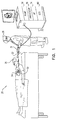
- FIG. 1 is a schematic pictorial illustration of a system 20 for cardiac ablation treatment, in accordance with an embodiment of the present invention.
- An operator 28 inserts an intra-body probe, such as a catheter 22, via the vascular system of a patient 26, into a chamber of the patient's heart 24.
- an intra-body probe such as a catheter 22
- the operator may advance the catheter into the left atrium and bring an ablation electrode 30 at a distal end of the catheter into contact with myocardial tissue that is to be monitored and/or ablated.
- Catheter 22 is connected at its proximal end to a handle 31, which is connected, in turn, to a console 32.
- Console 32 comprises a radiofrequency (RF) generator 34, which supplies electrical power to ablation electrode 30 in order to ablate the target tissue.
- An irrigation pump 38 supplies an irrigating fluid, such as a saline solution, through catheter 22 to ablation electrode 30. (The irrigating fluid is then passed into the blood during the ablation procedure, in order to help prevent blood clots from forming.)
- a processor 36 may be used to monitor the ablating current and/or control the current by controlling RF energy generator 34, either automatically or in response to inputs from operator 28.
- ECG electrocardiogram
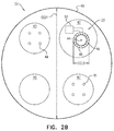
- Figs. 2A-B are schematic illustrations of catheter 22, in accordance with some embodiments of the present invention.
- Catheter 22 comprises an insertion tube 40, having a proximal end and a distal end.
- Ablation electrode 30 is disposed at the distal end of the tube, and a conducting element (e.g., a wire) 44 is configured to conduct an ablating current 52 from the proximal end of the tube to the ablation electrode.
- the insertion tube may be shaped to define a lumen 42, and conducting element 44 may run proximally-distally within lumen 42.
- a sensor 23 is configured to measure the amplitude of ablating current 52 at the distal end of the tube.
- sensor 23 is disposed at or near the distal end of the tube, typically within the tube.
- Sensor 23 may be embodied as shown in the figures and described hereinbelow. Alternatively, sensor 23 may comprise any other suitable current-measuring sensor.
- sensor 23 comprises a magnetic core 46 (comprising, for example, a ferromagnetic material such as ferrite).
- Magnetic core 46 is typically disposed within the tube (e.g., within lumen 42), near the distal end of the tube, and conducting element 44 passes through magnetic core 46.
- sensor 23 further comprises a coil 48, which is wound around the core.
- the coil is wound such that the resonant frequency of the resonant circuit formed by the inductance and parasitic capacitance of the coil is significantly higher than the frequency of ablating current 52.
- ablating current 52 passes through the magnetic core, the ablating current produces a magnetic field in the core, which in turn induces a voltage in coil 48.
- Circuitry 50 which is typically coupled to the coil, measures the induced voltage.
- the outer diameter OD1 of tube 40 is less than 4 mm.
- OD1 may be between 2 and 4 mm, e.g., approximately 3 mm.
- Embodiments of the present invention provide techniques for manufacturing core 46, coil 48, and circuitry 50, such that the above elements are sufficiently small to fit within the tube.
- the outer diameter OD2 of the core may be less than 2 mm, e.g., between 1 and 1.5 mm.
- the scope of the present invention includes shaping the core as a circle, ellipse, or any other suitable shape, and aligning the core in any suitable orientation with respect to the longitudinal axis of the tube.
- insertion tube 40 is further shaped to define one or more lumens, in addition to lumen 42.
- the insertion tube may be shaped to define an irrigating-fluid lumen 45, configured to deliver irrigating fluid from pump 38 ( Fig. 1 ) to the ablation electrode.
- the insertion tube may be further shaped to define a control-wire lumen 43, along which one or more control wires 49 run; control wires 49 may be manipulated, via handle 31, to steer and/or otherwise control the catheter.
- the catheter further comprises magnetic location sensors at the distal end of the catheter.
- the insertion tube may be further shaped to define a magnetic-sensor-wire lumen 47, along which run wires 51 that are connected to the magnetic navigation sensors.
- magnetic core 46 is placed far enough away from the location sensors - e.g., at least 10 mm from the location sensors - such that the magnetic core and the location sensors do not interfere with each other.
- the tube is not shaped to define a dedicated irrigating-fluid lumen. Instead, a fluid-delivery tube, which delivers irrigating fluid from pump 38, passes through the magnetic core. Such embodiments may allow space within the insertion tube to be used more efficiently.
- the scope of the present invention includes having any suitable number of distinct lumens within the insertion tube, along with any suitable numbers or types of wires, tubes, or other elements disposed within the lumens.
- conducting element 44 is wound one or more times around magnetic core 46.
- the measured amplitude of the induced voltage may be multiplied by a coefficient that is a function of, at least, (i) the number of windings of the conducting element around the core, and (ii) the number of windings of coil 48 around the core. (If conducting element 44 is not wound around the magnetic core, the value of (i) that is used is one half.)
- Circuitry 50 comprises inputs 70a and 70b, which are configured to receive the two ends of coil 48, as shown in Figs. 2A-B .
- Circuitry 50 further comprises a measurement unit 62, configured to measure the induced voltage in the coil.
- measurement unit 62 may comprise a voltmeter, configured to measure the induced voltage across a resistor 64. (The exact configuration of circuitry within the measurement unit is not shown in Fig. 3 .)
- measurement unit 62 further comprises a controller (CTRL) 66, such as the STM32L151RE (TM) microcontroller from ST (TM).
- CTRL controller
- controller 66 modulates the current on conducting element 44, at a frequency different from the frequency of the ablating current, to indicate the measured amplitude of the induced voltage.
- the sensor modulates onto the conducting element a feedback signal that is indicative of the measured amplitude of the induced voltage.
- the modulation is detected by receiving circuitry 72.
- Receiving circuitry 72 may be disposed at the proximal end of the catheter, such as within handle 31, as depicted in Fig. 2A , or within console 32 ( Fig. 1 ).
- the receiving circuitry ascertains, from the feedback signal, the amplitude of the induced voltage.
- receiving circuitry 72 then communicates the amplitude of the induced voltage to processor 36 ( Fig. 1 ), which estimates the amplitude of the ablating current based on the amplitude of the induced voltage.
- the processor may then control RF generator 34, e.g., by increasing or decreasing the power supplied by the generator.
- the processor may generate an output indicative of the estimate, and operator 28 ( Fig. 1 ) may control the generator in response thereto.
- circuitry 50 further comprises an energy-harvesting unit 56, such as, for example, the LTC3330 (TM) unit from Linear Technology (TM), or the MAX17710 (TM) unit from MAXIM (TM).
- Energy-harvesting unit 56 harvests energy from the ablating current, by rectifying the induced alternating-current (AC) voltage, and using the rectified direct-current (DC) voltage to charge a storage capacitor 58, which then powers measurement unit 62.
- AC induced alternating-current
- DC direct-current
- the energy harvested from the ablating current is typically only a small part of the total energy delivered by the ablating current, such that the harvesting of energy from the ablating current does not reduce the efficacy of the ablation procedure.
- the receiving circuitry comprises a current transformer, comprising circuitry 74 that comprises, for example, a preamplifier, a demodulator, a decoder, and/or other electronic components.
- the preamplifier amplifies the received signal for the demodulator, which then filters out, from the received signal, the ablation-current frequency.
- the decoder typically comprising a microcontroller such as the aforementioned STM32L151RE (TM) controller, then ascertains the amplitude of the induced voltage, and communicates with the processor, as described hereinabove.
- the processor rather than the receiving circuitry, ascertains the amplitude of the induced voltage from the feedback signal.
- the senor uses a different method from the method described above to provide feedback to the receiving circuitry.
- the sensor may use capacitive coupling to transmit a feedback signal over a separate conducting element.
Landscapes
- Health & Medical Sciences (AREA)
- Surgery (AREA)
- Engineering & Computer Science (AREA)
- Life Sciences & Earth Sciences (AREA)
- Biomedical Technology (AREA)
- Molecular Biology (AREA)
- Nuclear Medicine, Radiotherapy & Molecular Imaging (AREA)
- Plasma & Fusion (AREA)
- Physics & Mathematics (AREA)
- Heart & Thoracic Surgery (AREA)
- Medical Informatics (AREA)
- Otolaryngology (AREA)
- Animal Behavior & Ethology (AREA)
- General Health & Medical Sciences (AREA)
- Public Health (AREA)
- Veterinary Medicine (AREA)
- Cardiology (AREA)
- Surgical Instruments (AREA)
- Media Introduction/Drainage Providing Device (AREA)
Abstract
Description
- Embodiments of the present invention relate to ablation procedures, such as intracardiac ablation procedures, and associated systems and apparatus.
- Minimally-invasive intracardiac ablation is the treatment of choice for various types of arrhythmias. To perform such treatment, the physician typically inserts a catheter through the vascular system into the heart, brings the distal end of the catheter into contact with myocardial tissue in areas of abnormal electrical activity, and then energizes one or more electrodes at or near the distal end in order to create tissue necrosis.
-
US Patent 6,059,780 , whose disclosure is incorporated herein by reference, describes an ablation apparatus including a handpiece, an electrode extending from a handpiece distal end, a probe, a thermal sensor and an energy source. The electrode includes a distal end and a lumen, a cooling medium inlet conduit and a cooling medium exit conduit. Both conduits extend through the electrode lumen to an electrode distal end. A sidewall port, isolated from a cooling medium flowing in the inlet and outlet conduits, is formed in the electrode. The probe is at least partially positionable in the electrode lumen and configured to be advanced and retracted in and out of the sidewall aperture. The thermal sensor is supported by the probe. The electrode is coupled to an energy source. - European Application
0566726 , whose disclosure is incorporated herein by reference, describes systems for ablating tissue that measure the current and voltage delivered to the associated electrode assembly and generate measured current and voltage signals. The systems divide the measured voltage signal by the measured current signal to derive a measured tissue impedance signal. The systems perform control functions based upon the measured tissue impedance signal. - International Application
2013/156896 , whose disclosure is incorporated herein by reference, describes an energy application apparatus for applying energy to an object. An energy application unit applies energy to the object, wherein the energy application unit is adapted to use electrical current for applying the energy. A current measuring unit measures the electrical current used by the energy application unit and provides a signal being indicative of whether the energy is applied to the object based on the measured electrical current. The signal can be used by, for instance, a monitoring unit and/or a display unit for using and/or indicating the information whether energy is actually applied or not, without requiring a direct communication between the energy application unit and the monitoring unit and/or the display unit. -
US 2003/0187430 , whose disclosure is incorporated herein by reference, describes an electrode and a voltage-measurement reference device adapted to be positioned relative to a tissue load such that the load is generally located between the electrode and the reference device. A first wire and a second wire are electrically connected to the electrode. A power control system delivers RF current to the load through the first wire and measures the voltage across the load between the second wire and the reference device. The power control system measures the RF current through the first wire and determines the power delivered to the load using the measured current and voltage. The first and second wires function as thermocouple leads which, in combination with the electrode to which they are attached, form a thermocouple. The power control system monitors the voltage across the leads and determines the temperature at the electrode either during the delivery of current or alternatively, when current is not being delivered. -
US 2014/0243813 , whose disclosure is incorporated herein by reference, describes ablation systems and methods for providing feedback on lesion formation in real-time. The methods and systems assess absorptivity of tissue based on a degree of electric coupling or contact between an ablation electrode and the tissue. The absorptivity can then be used, along with other information, including, power levels and activation times, to provide real-time feedback on the lesions being created. Feedback may be provided, for example, in the form of estimated lesion volumes and other lesion characteristics. The methods and systems can provide estimated treatment times to achieve a desired lesion characteristic for a given degree of contact, as well as depth of a lesion being created. The degree of contact may be measured using different techniques, including the phase angle techniques and a coupling index. - There is provided, in accordance with some embodiments of the present invention, ablation apparatus. The apparatus includes an insertion tube, an ablation electrode disposed at a distal end of the tube, a conducting element, and a sensor. The conducting element conducts an ablating current from a proximal end of the tube to the ablation electrode, and the sensor measures an amplitude of the ablating current at the distal end of the tube.
- In some embodiments, the sensor is further configured to harvest energy from the ablating current.
- In some embodiments, the sensor is disposed within the tube.
- In some embodiments, the sensor is disposed at the distal end of the tube.
- In some embodiments, an outer diameter of the tube is less than 4 mm.
- In some embodiments, the sensor is configured to measure the amplitude of the ablating current by measuring an amplitude of a voltage induced by a magnetic field that is produced by the ablating current.
- In some embodiments, the sensor includes:
- a magnetic core, through which the conducting element passes;
- a coil wound around the core; and
- circuitry, which is coupled to the coil, and is configured to measure the amplitude of the ablating current by measuring an amplitude of a voltage induced in the coil by a magnetic field in the core that is produced by the ablating current.
- In some embodiments, the apparatus further includes a fluid-delivery tube, configured to deliver fluid from the proximal end of the insertion tube to the ablation electrode, passing through the magnetic core.
- In some embodiments, an outer diameter of the core is less than 2 mm.
- In some embodiments, the conducting element is wound one or more times around the magnetic core.
- In some embodiments, the sensor is further configured to modulate onto the conducting element a feedback signal that is indicative of the measured amplitude of the induced voltage.
- In some embodiments, the apparatus further includes receiving circuitry configured to ascertain, from the feedback signal, the amplitude of the induced voltage.
- In some embodiments, the apparatus further includes a processor configured to estimate an amplitude of the ablating current, based on the amplitude of the induced voltage.
- In some embodiments, the processor is further configured to control a generator of the ablating current, in response to the estimate.
- There is further provided, in accordance with some embodiments of the present invention, a method for estimating an amplitude of an ablating current. An insertion tube, an ablation electrode disposed at a distal end of the tube, and a conducting element, configured to conduct an ablating current from a proximal end of the tube to the ablation electrode, are provided. The ablating current is passed over the conducting element, and an amplitude of the ablating current at the distal end of the tube is measured.
- In some embodiments, the method further includes, prior to passing the ablating current over the conducting element, inserting the tube into a heart of a patient.
- In some embodiments, measuring the amplitude of the ablating current includes using a sensor disposed within the tube to measure the amplitude.
- In some embodiments, measuring the amplitude of the ablating current includes measuring the amplitude of the ablating current by measuring an amplitude of a voltage induced by a magnetic field that is produced by the ablating current.
- In some embodiments, passing the ablating current over the conducting element includes passing the ablating current through a magnetic core, and measuring the amplitude of the ablating current includes measuring the amplitude of the ablating current by measuring an amplitude of a voltage induced by a magnetic field in the core that is produced by the ablating current.
- In some embodiments, the method further includes modulating onto the conducting element a feedback signal that is indicative of the measured amplitude of the induced voltage.
- In some embodiments, the method further includes controlling a generator of the ablating current, in response to measuring the amplitude of the ablating current.
- There is further provided, in accordance with some embodiments of the present invention, a method for manufacturing ablation apparatus. An insertion tube is provided, an ablation electrode being disposed at a distal end of the tube. A conducting element is passed between a proximal end of the tube and the ablation electrode, the conducting element being configured to conduct an ablating current from the proximal end of the tube to the ablation electrode. A sensor is placed within the tube, the sensor being configured to measure an amplitude of the ablating current at the distal end of the tube.
- In some embodiments, the sensor includes a magnetic core, and passing the conducting element between the proximal end of the tube and the ablation electrode includes passing the conducting element through the magnetic core.
- In some embodiments, the method further includes winding the conducting element one or more times around the magnetic core.
- In some embodiments, the method further includes passing a fluid-delivery tube, configured to deliver fluid from the proximal end of the insertion tube to the ablation electrode, through the magnetic core.
- The present invention will be more fully understood from the following detailed description of embodiments thereof, taken together with the drawings, in which:
-
-
Fig. 1 is a schematic pictorial illustration of a system for cardiac ablation treatment, in accordance with an embodiment of the present invention; -
Figs. 2A-B are schematic illustrations of a catheter, in accordance with some embodiments of the present invention; and -
Fig. 3 is a schematic illustration of a sensor, in accordance with some embodiments of the present invention. - When performing an ablation procedure, a catheter, comprising an insertion tube, is inserted into the patient's heart, and an ablation electrode disposed at the distal end of the tube is brought into contact with cardiac tissue of the patient. To ablate the tissue, an ablating current is then passed from a radiofrequency (RF) generator at the proximal end of the tube to the ablation electrode.
- To ensure that the procedure is safely and effectively performed, it is advantageous for the operating physician to monitor the amplitude of the ablating current. One solution is to place a sensor at the proximal end of the tube, e.g., by integrating such a sensor with the RF generator. However, this solution may be suboptimal, in that, as the ablating current passes toward the distal end of the tube, some of the ablating current may be lost to parasitic capacitance, such that the amplitude of the ablating current that is actually delivered to the tissue may be less than the amplitude that is measured at the proximal end of the tube.
- Embodiments of the present invention provide a different solution, by which the amplitude of the ablating current at the distal end of the tube is measured. In such embodiments, a sensor may be placed at or near the distal end of the tube, typically within the tube. The sensor may comprise, for example, a magnetic core, a coil wound around the core, and circuitry coupled to the coil. The conducting element (e.g., the wire) that delivers the ablating current to the ablation electrode passes through the magnetic core, such that a magnetic field is produced in the core by the ablating current. The magnetic field induces a voltage in the coil, and the circuitry measures the amplitude of the induced voltage. The amplitude of the ablating current may then be estimated, based on the amplitude of the induced voltage.
- In general, as used within the claims and description of the present application, any reference to measurement of the ablating current may include within its scope any form of direct or indirect measurement. For example, the above-described estimation of the amplitude of the ablating current based on the amplitude of the induced voltage may be referred to as a measurement of the ablating current.
- Reference is initially made to
Fig. 1 , which is a schematic pictorial illustration of asystem 20 for cardiac ablation treatment, in accordance with an embodiment of the present invention. An operator 28 (such as an interventional cardiologist) inserts an intra-body probe, such as acatheter 22, via the vascular system of apatient 26, into a chamber of the patient'sheart 24. For example, to treat atrial fibrillation, the operator may advance the catheter into the left atrium and bring anablation electrode 30 at a distal end of the catheter into contact with myocardial tissue that is to be monitored and/or ablated. -
Catheter 22 is connected at its proximal end to ahandle 31, which is connected, in turn, to aconsole 32.Console 32 comprises a radiofrequency (RF)generator 34, which supplies electrical power toablation electrode 30 in order to ablate the target tissue. Anirrigation pump 38 supplies an irrigating fluid, such as a saline solution, throughcatheter 22 toablation electrode 30. (The irrigating fluid is then passed into the blood during the ablation procedure, in order to help prevent blood clots from forming.) Aprocessor 36 may be used to monitor the ablating current and/or control the current by controllingRF energy generator 34, either automatically or in response to inputs fromoperator 28. Before, during, and/or after the procedure, an electrocardiogram (ECG)recorder 60 may record an ECG of the patient. - Reference is now made to
Figs. 2A-B , which are schematic illustrations ofcatheter 22, in accordance with some embodiments of the present invention.Catheter 22 comprises aninsertion tube 40, having a proximal end and a distal end.Ablation electrode 30 is disposed at the distal end of the tube, and a conducting element (e.g., a wire) 44 is configured to conduct an ablating current 52 from the proximal end of the tube to the ablation electrode. For example, as shown inFig. 2B , the insertion tube may be shaped to define alumen 42, and conductingelement 44 may run proximally-distally withinlumen 42. Asensor 23 is configured to measure the amplitude of ablating current 52 at the distal end of the tube. Typically,sensor 23 is disposed at or near the distal end of the tube, typically within the tube.Sensor 23 may be embodied as shown in the figures and described hereinbelow. Alternatively,sensor 23 may comprise any other suitable current-measuring sensor. - In the particular embodiment shown in
Figs. 2A-B ,sensor 23 comprises a magnetic core 46 (comprising, for example, a ferromagnetic material such as ferrite).Magnetic core 46 is typically disposed within the tube (e.g., within lumen 42), near the distal end of the tube, and conductingelement 44 passes throughmagnetic core 46. As further shown inFigs. 2A-B ,sensor 23 further comprises acoil 48, which is wound around the core. (Typically, the coil is wound such that the resonant frequency of the resonant circuit formed by the inductance and parasitic capacitance of the coil is significantly higher than the frequency of ablating current 52.) As ablating current 52 passes through the magnetic core, the ablating current produces a magnetic field in the core, which in turn induces a voltage incoil 48.Circuitry 50, which is typically coupled to the coil, measures the induced voltage. - Typically, the outer diameter OD1 of
tube 40 is less than 4 mm. For example, OD1 may be between 2 and 4 mm, e.g., approximately 3 mm. Embodiments of the present invention provide techniques for manufacturingcore 46,coil 48, andcircuitry 50, such that the above elements are sufficiently small to fit within the tube. For example, the outer diameter OD2 of the core may be less than 2 mm, e.g., between 1 and 1.5 mm. The scope of the present invention includes shaping the core as a circle, ellipse, or any other suitable shape, and aligning the core in any suitable orientation with respect to the longitudinal axis of the tube. - In some embodiments,
insertion tube 40 is further shaped to define one or more lumens, in addition tolumen 42. For example, the insertion tube may be shaped to define an irrigating-fluid lumen 45, configured to deliver irrigating fluid from pump 38 (Fig. 1 ) to the ablation electrode. The insertion tube may be further shaped to define a control-wire lumen 43, along which one ormore control wires 49 run;control wires 49 may be manipulated, viahandle 31, to steer and/or otherwise control the catheter. In some embodiments, the catheter further comprises magnetic location sensors at the distal end of the catheter. In such embodiments, the insertion tube may be further shaped to define a magnetic-sensor-wire lumen 47, along which runwires 51 that are connected to the magnetic navigation sensors. Typically,magnetic core 46 is placed far enough away from the location sensors - e.g., at least 10 mm from the location sensors - such that the magnetic core and the location sensors do not interfere with each other. - In some embodiments, the tube is not shaped to define a dedicated irrigating-fluid lumen. Instead, a fluid-delivery tube, which delivers irrigating fluid from
pump 38, passes through the magnetic core. Such embodiments may allow space within the insertion tube to be used more efficiently. - In general, it is noted that the scope of the present invention includes having any suitable number of distinct lumens within the insertion tube, along with any suitable numbers or types of wires, tubes, or other elements disposed within the lumens.
- In some embodiments, conducting
element 44 is wound one or more times aroundmagnetic core 46. To estimate the amplitude of the ablating current, the measured amplitude of the induced voltage may be multiplied by a coefficient that is a function of, at least, (i) the number of windings of the conducting element around the core, and (ii) the number of windings ofcoil 48 around the core. (If conductingelement 44 is not wound around the magnetic core, the value of (i) that is used is one half.) - Reference is now additionally made to
Fig. 3 , which is a schematic illustration ofcircuitry 50, in accordance with some embodiments of the present invention.Circuitry 50 comprisesinputs coil 48, as shown inFigs. 2A-B .Circuitry 50 further comprises ameasurement unit 62, configured to measure the induced voltage in the coil. For example,measurement unit 62 may comprise a voltmeter, configured to measure the induced voltage across aresistor 64. (The exact configuration of circuitry within the measurement unit is not shown inFig. 3 .) - Typically,
measurement unit 62 further comprises a controller (CTRL) 66, such as the STM32L151RE (TM) microcontroller from ST (TM). By controlling a switch 68 (e.g., a bipolar MOSFET switch),controller 66 modulates the current on conductingelement 44, at a frequency different from the frequency of the ablating current, to indicate the measured amplitude of the induced voltage. In this manner, the sensor modulates onto the conducting element a feedback signal that is indicative of the measured amplitude of the induced voltage. - Typically, the modulation is detected by receiving
circuitry 72. Receivingcircuitry 72 may be disposed at the proximal end of the catheter, such as withinhandle 31, as depicted inFig. 2A , or within console 32 (Fig. 1 ). The receiving circuitry ascertains, from the feedback signal, the amplitude of the induced voltage. Typically, receivingcircuitry 72 then communicates the amplitude of the induced voltage to processor 36 (Fig. 1 ), which estimates the amplitude of the ablating current based on the amplitude of the induced voltage. In response to the estimate, the processor may then controlRF generator 34, e.g., by increasing or decreasing the power supplied by the generator. Alternatively or additionally, the processor may generate an output indicative of the estimate, and operator 28 (Fig. 1 ) may control the generator in response thereto. - Typically,
circuitry 50 further comprises an energy-harvestingunit 56, such as, for example, the LTC3330 (TM) unit from Linear Technology (TM), or the MAX17710 (TM) unit from MAXIM (TM). Energy-harvestingunit 56 harvests energy from the ablating current, by rectifying the induced alternating-current (AC) voltage, and using the rectified direct-current (DC) voltage to charge astorage capacitor 58, which then powersmeasurement unit 62. In such embodiments, it may not be necessary to supply the sensor with a battery or other dedicated power source, since the energy harvested from the ablating current may be sufficient to power the sensor. (It is noted that the energy harvested from the ablating current is typically only a small part of the total energy delivered by the ablating current, such that the harvesting of energy from the ablating current does not reduce the efficacy of the ablation procedure.) - Typically, the receiving circuitry comprises a current transformer, comprising
circuitry 74 that comprises, for example, a preamplifier, a demodulator, a decoder, and/or other electronic components. The preamplifier amplifies the received signal for the demodulator, which then filters out, from the received signal, the ablation-current frequency. The decoder, typically comprising a microcontroller such as the aforementioned STM32L151RE (TM) controller, then ascertains the amplitude of the induced voltage, and communicates with the processor, as described hereinabove. - In alternative embodiments, the processor, rather than the receiving circuitry, ascertains the amplitude of the induced voltage from the feedback signal.
- In some embodiments, the sensor uses a different method from the method described above to provide feedback to the receiving circuitry. For example, the sensor may use capacitive coupling to transmit a feedback signal over a separate conducting element.
- It will be appreciated by persons skilled in the art that the present invention is not limited to what has been particularly shown and described hereinabove. Rather, the scope of the present invention includes both combinations and subcombinations of the various features described hereinabove, as well as variations and modifications thereof that are not in the prior art, which would occur to persons skilled in the art upon reading the foregoing description. Documents incorporated by reference in the present patent application are to be considered an integral part of the application except that to the extent any terms are defined in these incorporated documents in a manner that conflicts with the definitions made explicitly or implicitly in the present specification, only the definitions in the present specification should be considered.
-
- 1. A method for estimating an amplitude of an ablating current, the method comprising:
- providing (i) an insertion tube, (ii) an ablation electrode disposed at a distal end of the tube, and (iii) a conducting element, configured to conduct an ablating current from a proximal end of the tube to the ablation electrode;
- passing the ablating current over the conducting element; and
- measuring an amplitude of the ablating current at the distal end of the tube.
- 2. The method according to aspect 1, further comprising, prior to passing the ablating current over the conducting element, inserting the tube into a heart of a patient.
- 3. The method according to aspect 1, wherein measuring the amplitude of the ablating current comprises using a sensor disposed within the tube to measure the amplitude.
- 4. The method according to aspect 1, wherein measuring the amplitude of the ablating current comprises measuring the amplitude of the ablating current by measuring an amplitude of a voltage induced by a magnetic field that is produced by the ablating current.
- 5. The method according to aspect 4, wherein passing the ablating current over the conducting element comprises passing the ablating current through a magnetic core, and wherein measuring the amplitude of the ablating current comprises measuring the amplitude of the ablating current by measuring an amplitude of a voltage induced by a magnetic field in the core that is produced by the ablating current.
- 6. The method according to aspect 4, further comprising modulating onto the conducting element a feedback signal that is indicative of the measured amplitude of the induced voltage.
- 7. The method according to aspect 1, further comprising controlling a generator of the ablating current, in response to measuring the amplitude of the ablating current.
Claims (18)
- Ablation apparatus, comprising:an insertion tube;an ablation electrode disposed at a distal end of the tube;a conducting element, configured to conduct an ablating current from a proximal end of the tube to the ablation electrode; anda sensor configured to measure an amplitude of the ablating current at the distal end of the tube.
- The apparatus according to claim 1, wherein the sensor is further configured to harvest energy from the ablating current.
- The apparatus according to claim 1, wherein the sensor is disposed within the tube.
- The apparatus according to claim 3, wherein the sensor is disposed at the distal end of the tube.
- The apparatus according to claim 3, wherein an outer diameter of the tube is less than 4 mm.
- The apparatus according to claim 1, wherein the sensor is configured to measure the amplitude of the ablating current by measuring an amplitude of a voltage induced by a magnetic field that is produced by the ablating current.
- The apparatus according to claim 6, wherein the sensor comprises:a magnetic core, through which the conducting element passes;a coil wound around the core; andcircuitry, which is coupled to the coil, and is configured to measure the amplitude of the ablating current by measuring an amplitude of a voltage induced in the coil by a magnetic field in the core that is produced by the ablating current.
- The apparatus according to claim 7, further comprising a fluid-delivery tube, configured to deliver fluid from the proximal end of the insertion tube to the ablation electrode, passing through the magnetic core.
- The apparatus according to claim 7, wherein an outer diameter of the core is less than 2 mm.
- The apparatus according to claim 7, wherein the conducting element is wound one or more times around the magnetic core.
- The apparatus according to claim 6, wherein the sensor is further configured to modulate onto the conducting element a feedback signal that is indicative of the measured amplitude of the induced voltage.
- The apparatus according to claim 11, further comprising receiving circuitry configured to ascertain, from the feedback signal, the amplitude of the induced voltage.
- The apparatus according to claim 6, further comprising a processor configured to estimate the amplitude of the ablating current, based on the amplitude of the induced voltage.
- The apparatus according to claim 13, wherein the processor is further configured to control a generator of the ablating current, in response to the estimate.
- A method for manufacturing ablation apparatus, the method comprising:providing an insertion tube, an ablation electrode being disposed at a distal end of the tube;passing a conducting element between a proximal end of the tube and the ablation electrode, the conducting element being configured to conduct an ablating current from the proximal end of the tube to the ablation electrode; andplacing a sensor within the tube, the sensor being configured to measure an amplitude of the ablating current at the distal end of the tube.
- The method according to claim 15, wherein the sensor includes a magnetic core, and wherein passing the conducting element between the proximal end of the tube and the ablation electrode comprises passing the conducting element through the magnetic core.
- The method according to claim 16, further comprising winding the conducting element one or more times around the magnetic core.
- The method according to claim 16, further comprising passing a fluid-delivery tube, configured to deliver fluid from the proximal end of the insertion tube to the ablation electrode, through the magnetic core.
Applications Claiming Priority (1)
| Application Number | Priority Date | Filing Date | Title |
|---|---|---|---|
| US14/860,034 US10357309B2 (en) | 2015-09-21 | 2015-09-21 | Ablation current measurement |
Publications (2)
| Publication Number | Publication Date |
|---|---|
| EP3143957A1 true EP3143957A1 (en) | 2017-03-22 |
| EP3143957B1 EP3143957B1 (en) | 2021-05-12 |
Family
ID=56979427
Family Applications (1)
| Application Number | Title | Priority Date | Filing Date |
|---|---|---|---|
| EP16189715.2A Active EP3143957B1 (en) | 2015-09-21 | 2016-09-20 | Ablation current measurement |
Country Status (7)
| Country | Link |
|---|---|
| US (1) | US10357309B2 (en) |
| EP (1) | EP3143957B1 (en) |
| JP (1) | JP6887774B2 (en) |
| CN (1) | CN106821491B (en) |
| AU (1) | AU2016216555A1 (en) |
| CA (1) | CA2940949A1 (en) |
| IL (1) | IL247434B (en) |
Families Citing this family (9)
| Publication number | Priority date | Publication date | Assignee | Title |
|---|---|---|---|---|
| US11389232B2 (en) | 2006-06-28 | 2022-07-19 | Kardium Inc. | Apparatus and method for intra-cardiac mapping and ablation |
| US9119633B2 (en) | 2006-06-28 | 2015-09-01 | Kardium Inc. | Apparatus and method for intra-cardiac mapping and ablation |
| US8906011B2 (en) | 2007-11-16 | 2014-12-09 | Kardium Inc. | Medical device for use in bodily lumens, for example an atrium |
| US9693832B2 (en) | 2012-05-21 | 2017-07-04 | Kardium Inc. | Systems and methods for selecting, activating, or selecting and activating transducers |
| US10827977B2 (en) | 2012-05-21 | 2020-11-10 | Kardium Inc. | Systems and methods for activating transducers |
| US9198592B2 (en) | 2012-05-21 | 2015-12-01 | Kardium Inc. | Systems and methods for activating transducers |
| US10722184B2 (en) | 2014-11-17 | 2020-07-28 | Kardium Inc. | Systems and methods for selecting, activating, or selecting and activating transducers |
| US10368936B2 (en) | 2014-11-17 | 2019-08-06 | Kardium Inc. | Systems and methods for selecting, activating, or selecting and activating transducers |
| EP3594561B1 (en) | 2017-03-08 | 2022-06-29 | Koito Manufacturing Co., Ltd. | Lamp for vehicle |
Citations (8)
| Publication number | Priority date | Publication date | Assignee | Title |
|---|---|---|---|---|
| EP0566726A1 (en) | 1991-11-08 | 1993-10-27 | Ep Technologies, Inc. | Systems and methods for ablating tissue while monitoring tissue impedance |
| US6059780A (en) | 1995-08-15 | 2000-05-09 | Rita Medical Systems, Inc. | Multiple antenna ablation apparatus and method with cooling element |
| US20030187430A1 (en) | 2002-03-15 | 2003-10-02 | Vorisek James C. | System and method for measuring power at tissue during RF ablation |
| US20120123408A1 (en) * | 2008-03-27 | 2012-05-17 | Bovie Medical Corporation | Laparoscopic electrosurgical electrical leakage detection |
| US20130156896A1 (en) | 2011-12-14 | 2013-06-20 | Casetech Gmbh | Cellulose-based food casing having a fungicidal finish and a method for protecting cellulose-based food casings from mold infestation |
| WO2013156896A2 (en) * | 2012-04-19 | 2013-10-24 | Koninklijke Philips N.V. | Energy application apparatus |
| US20140243813A1 (en) | 2007-11-16 | 2014-08-28 | St. Jude Medical, Atrial Fibrillation Division, Inc. | Device and method for real-time lesion estimation during ablation |
| US20140276755A1 (en) * | 2013-03-12 | 2014-09-18 | Boston Scientific Scimed, Inc. | Medical systems and methods for modulating nerves |
Family Cites Families (11)
| Publication number | Priority date | Publication date | Assignee | Title |
|---|---|---|---|---|
| JPS5977844A (en) * | 1982-10-28 | 1984-05-04 | 持田製薬株式会社 | Safety apparatus for laser knife |
| US6161543A (en) * | 1993-02-22 | 2000-12-19 | Epicor, Inc. | Methods of epicardial ablation for creating a lesion around the pulmonary veins |
| US8979834B2 (en) * | 2008-03-27 | 2015-03-17 | Bovie Medical Corporation | Laparoscopic electrosurgical electrical leakage detection |
| US20120176103A1 (en) * | 2009-09-03 | 2012-07-12 | Verivolt, Llc | Voltage Conversion and/or Electrical Measurements from 400 Volts Upwards |
| CN101969720B (en) * | 2010-09-15 | 2013-09-18 | 成都芯源系统有限公司 | LED bypass control circuit and control method |
| GB201021032D0 (en) * | 2010-12-10 | 2011-01-26 | Creo Medical Ltd | Electrosurgical apparatus |
| US9044244B2 (en) * | 2010-12-10 | 2015-06-02 | Biosense Webster (Israel), Ltd. | System and method for detection of metal disturbance based on mutual inductance measurement |
| US9084539B2 (en) * | 2012-02-02 | 2015-07-21 | Volcano Corporation | Wireless pressure wire system with integrated power |
| CN103326393B (en) * | 2012-03-22 | 2016-03-30 | 张家港智电柔性输配电技术研究所有限公司 | A kind of redundant power supply power supply of H bridge cascade converter |
| US9116179B2 (en) * | 2012-12-17 | 2015-08-25 | Covidien Lp | System and method for voltage and current sensing |
| CN105682597B (en) * | 2013-11-07 | 2018-06-12 | 圣犹达医疗用品心脏病学部门有限公司 | Medical device with contact force sensing tip |
-
2015
- 2015-09-21 US US14/860,034 patent/US10357309B2/en not_active Expired - Fee Related
-
2016
- 2016-08-16 AU AU2016216555A patent/AU2016216555A1/en not_active Abandoned
- 2016-08-23 IL IL247434A patent/IL247434B/en active IP Right Grant
- 2016-09-01 CA CA2940949A patent/CA2940949A1/en not_active Abandoned
- 2016-09-20 EP EP16189715.2A patent/EP3143957B1/en active Active
- 2016-09-20 JP JP2016182762A patent/JP6887774B2/en not_active Expired - Fee Related
- 2016-09-21 CN CN201610839918.4A patent/CN106821491B/en not_active Expired - Fee Related
Patent Citations (8)
| Publication number | Priority date | Publication date | Assignee | Title |
|---|---|---|---|---|
| EP0566726A1 (en) | 1991-11-08 | 1993-10-27 | Ep Technologies, Inc. | Systems and methods for ablating tissue while monitoring tissue impedance |
| US6059780A (en) | 1995-08-15 | 2000-05-09 | Rita Medical Systems, Inc. | Multiple antenna ablation apparatus and method with cooling element |
| US20030187430A1 (en) | 2002-03-15 | 2003-10-02 | Vorisek James C. | System and method for measuring power at tissue during RF ablation |
| US20140243813A1 (en) | 2007-11-16 | 2014-08-28 | St. Jude Medical, Atrial Fibrillation Division, Inc. | Device and method for real-time lesion estimation during ablation |
| US20120123408A1 (en) * | 2008-03-27 | 2012-05-17 | Bovie Medical Corporation | Laparoscopic electrosurgical electrical leakage detection |
| US20130156896A1 (en) | 2011-12-14 | 2013-06-20 | Casetech Gmbh | Cellulose-based food casing having a fungicidal finish and a method for protecting cellulose-based food casings from mold infestation |
| WO2013156896A2 (en) * | 2012-04-19 | 2013-10-24 | Koninklijke Philips N.V. | Energy application apparatus |
| US20140276755A1 (en) * | 2013-03-12 | 2014-09-18 | Boston Scientific Scimed, Inc. | Medical systems and methods for modulating nerves |
Also Published As
| Publication number | Publication date |
|---|---|
| JP6887774B2 (en) | 2021-06-16 |
| IL247434B (en) | 2020-04-30 |
| CA2940949A1 (en) | 2017-03-21 |
| US10357309B2 (en) | 2019-07-23 |
| CN106821491A (en) | 2017-06-13 |
| AU2016216555A1 (en) | 2017-04-06 |
| US20170079712A1 (en) | 2017-03-23 |
| CN106821491B (en) | 2021-06-11 |
| EP3143957B1 (en) | 2021-05-12 |
| JP2017060758A (en) | 2017-03-30 |
| IL247434A0 (en) | 2016-12-29 |
Similar Documents
| Publication | Publication Date | Title |
|---|---|---|
| EP3143957B1 (en) | Ablation current measurement | |
| EP4294301B1 (en) | Contact quality system | |
| US9060778B2 (en) | Intermittent short circuit detection on a multi-electrode catheter | |
| US9216050B2 (en) | Detection of microbubble formation during catheter ablation | |
| CN104582619B (en) | System for organizing contact during detecting ablation | |
| JP2019076731A (en) | Esophageal probe with transmitting coils | |
| CA2950609A1 (en) | Sheath visualization method by means of impedance localization and magnetic information | |
| US11534227B2 (en) | High-resolution mapping of tissue with pacing | |
| EP3375397B1 (en) | Estimation of tissue thickness from rate of change of catheter temperature | |
| US20190350490A1 (en) | Methods and systems for enhanced mapping of tissue | |
| CN109288584B (en) | Tissue thickness using pulsed power | |
| EP2840997B1 (en) | Detection of microbubble formation during an ablation procedure | |
| CN113995499A (en) | Using a focal catheter with contact force and temperature sensors to control irreversible electroporation ablation | |
| EP4505941A1 (en) | Impedance-based navigation of sheath | |
| CN122005052A (en) | Tissue proximity index threshold for cardiac ablation |
Legal Events
| Date | Code | Title | Description |
|---|---|---|---|
| PUAI | Public reference made under article 153(3) epc to a published international application that has entered the european phase |
Free format text: ORIGINAL CODE: 0009012 |
|
| STAA | Information on the status of an ep patent application or granted ep patent |
Free format text: STATUS: THE APPLICATION HAS BEEN PUBLISHED |
|
| AK | Designated contracting states |
Kind code of ref document: A1 Designated state(s): AL AT BE BG CH CY CZ DE DK EE ES FI FR GB GR HR HU IE IS IT LI LT LU LV MC MK MT NL NO PL PT RO RS SE SI SK SM TR |
|
| AX | Request for extension of the european patent |
Extension state: BA ME |
|
| STAA | Information on the status of an ep patent application or granted ep patent |
Free format text: STATUS: REQUEST FOR EXAMINATION WAS MADE |
|
| 17P | Request for examination filed |
Effective date: 20170612 |
|
| RBV | Designated contracting states (corrected) |
Designated state(s): AL AT BE BG CH CY CZ DE DK EE ES FI FR GB GR HR HU IE IS IT LI LT LU LV MC MK MT NL NO PL PT RO RS SE SI SK SM TR |
|
| GRAP | Despatch of communication of intention to grant a patent |
Free format text: ORIGINAL CODE: EPIDOSNIGR1 |
|
| STAA | Information on the status of an ep patent application or granted ep patent |
Free format text: STATUS: GRANT OF PATENT IS INTENDED |
|
| RIC1 | Information provided on ipc code assigned before grant |
Ipc: A61B 18/14 20060101AFI20201118BHEP Ipc: A61B 18/00 20060101ALN20201118BHEP |
|
| INTG | Intention to grant announced |
Effective date: 20201201 |
|
| GRAJ | Information related to disapproval of communication of intention to grant by the applicant or resumption of examination proceedings by the epo deleted |
Free format text: ORIGINAL CODE: EPIDOSDIGR1 |
|
| STAA | Information on the status of an ep patent application or granted ep patent |
Free format text: STATUS: REQUEST FOR EXAMINATION WAS MADE |
|
| INTC | Intention to grant announced (deleted) | ||
| GRAP | Despatch of communication of intention to grant a patent |
Free format text: ORIGINAL CODE: EPIDOSNIGR1 |
|
| GRAJ | Information related to disapproval of communication of intention to grant by the applicant or resumption of examination proceedings by the epo deleted |
Free format text: ORIGINAL CODE: EPIDOSDIGR1 |
|
| RIC1 | Information provided on ipc code assigned before grant |
Ipc: A61B 18/14 20060101AFI20210115BHEP Ipc: A61B 18/00 20060101ALN20210115BHEP |
|
| GRAP | Despatch of communication of intention to grant a patent |
Free format text: ORIGINAL CODE: EPIDOSNIGR1 |
|
| STAA | Information on the status of an ep patent application or granted ep patent |
Free format text: STATUS: GRANT OF PATENT IS INTENDED |
|
| RIC1 | Information provided on ipc code assigned before grant |
Ipc: A61B 18/00 20060101ALN20210211BHEP Ipc: A61B 18/14 20060101AFI20210211BHEP |
|
| INTG | Intention to grant announced |
Effective date: 20210303 |
|
| GRAS | Grant fee paid |
Free format text: ORIGINAL CODE: EPIDOSNIGR3 |
|
| GRAA | (expected) grant |
Free format text: ORIGINAL CODE: 0009210 |
|
| STAA | Information on the status of an ep patent application or granted ep patent |
Free format text: STATUS: THE PATENT HAS BEEN GRANTED |
|
| AK | Designated contracting states |
Kind code of ref document: B1 Designated state(s): AL AT BE BG CH CY CZ DE DK EE ES FI FR GB GR HR HU IE IS IT LI LT LU LV MC MK MT NL NO PL PT RO RS SE SI SK SM TR |
|
| REG | Reference to a national code |
Ref country code: GB Ref legal event code: FG4D |
|
| REG | Reference to a national code |
Ref country code: CH Ref legal event code: EP |
|
| REG | Reference to a national code |
Ref country code: DE Ref legal event code: R096 Ref document number: 602016057694 Country of ref document: DE |
|
| REG | Reference to a national code |
Ref country code: IE Ref legal event code: FG4D |
|
| REG | Reference to a national code |
Ref country code: AT Ref legal event code: REF Ref document number: 1391653 Country of ref document: AT Kind code of ref document: T Effective date: 20210615 |
|
| REG | Reference to a national code |
Ref country code: NL Ref legal event code: FP |
|
| REG | Reference to a national code |
Ref country code: LT Ref legal event code: MG9D |
|
| REG | Reference to a national code |
Ref country code: AT Ref legal event code: MK05 Ref document number: 1391653 Country of ref document: AT Kind code of ref document: T Effective date: 20210512 |
|
| PG25 | Lapsed in a contracting state [announced via postgrant information from national office to epo] |
Ref country code: LT Free format text: LAPSE BECAUSE OF FAILURE TO SUBMIT A TRANSLATION OF THE DESCRIPTION OR TO PAY THE FEE WITHIN THE PRESCRIBED TIME-LIMIT Effective date: 20210512 Ref country code: FI Free format text: LAPSE BECAUSE OF FAILURE TO SUBMIT A TRANSLATION OF THE DESCRIPTION OR TO PAY THE FEE WITHIN THE PRESCRIBED TIME-LIMIT Effective date: 20210512 Ref country code: HR Free format text: LAPSE BECAUSE OF FAILURE TO SUBMIT A TRANSLATION OF THE DESCRIPTION OR TO PAY THE FEE WITHIN THE PRESCRIBED TIME-LIMIT Effective date: 20210512 Ref country code: BG Free format text: LAPSE BECAUSE OF FAILURE TO SUBMIT A TRANSLATION OF THE DESCRIPTION OR TO PAY THE FEE WITHIN THE PRESCRIBED TIME-LIMIT Effective date: 20210812 Ref country code: AT Free format text: LAPSE BECAUSE OF FAILURE TO SUBMIT A TRANSLATION OF THE DESCRIPTION OR TO PAY THE FEE WITHIN THE PRESCRIBED TIME-LIMIT Effective date: 20210512 |
|
| PG25 | Lapsed in a contracting state [announced via postgrant information from national office to epo] |
Ref country code: PT Free format text: LAPSE BECAUSE OF FAILURE TO SUBMIT A TRANSLATION OF THE DESCRIPTION OR TO PAY THE FEE WITHIN THE PRESCRIBED TIME-LIMIT Effective date: 20210913 Ref country code: NO Free format text: LAPSE BECAUSE OF FAILURE TO SUBMIT A TRANSLATION OF THE DESCRIPTION OR TO PAY THE FEE WITHIN THE PRESCRIBED TIME-LIMIT Effective date: 20210812 Ref country code: PL Free format text: LAPSE BECAUSE OF FAILURE TO SUBMIT A TRANSLATION OF THE DESCRIPTION OR TO PAY THE FEE WITHIN THE PRESCRIBED TIME-LIMIT Effective date: 20210512 Ref country code: ES Free format text: LAPSE BECAUSE OF FAILURE TO SUBMIT A TRANSLATION OF THE DESCRIPTION OR TO PAY THE FEE WITHIN THE PRESCRIBED TIME-LIMIT Effective date: 20210512 Ref country code: SE Free format text: LAPSE BECAUSE OF FAILURE TO SUBMIT A TRANSLATION OF THE DESCRIPTION OR TO PAY THE FEE WITHIN THE PRESCRIBED TIME-LIMIT Effective date: 20210512 Ref country code: RS Free format text: LAPSE BECAUSE OF FAILURE TO SUBMIT A TRANSLATION OF THE DESCRIPTION OR TO PAY THE FEE WITHIN THE PRESCRIBED TIME-LIMIT Effective date: 20210512 Ref country code: LV Free format text: LAPSE BECAUSE OF FAILURE TO SUBMIT A TRANSLATION OF THE DESCRIPTION OR TO PAY THE FEE WITHIN THE PRESCRIBED TIME-LIMIT Effective date: 20210512 Ref country code: IS Free format text: LAPSE BECAUSE OF FAILURE TO SUBMIT A TRANSLATION OF THE DESCRIPTION OR TO PAY THE FEE WITHIN THE PRESCRIBED TIME-LIMIT Effective date: 20210912 Ref country code: GR Free format text: LAPSE BECAUSE OF FAILURE TO SUBMIT A TRANSLATION OF THE DESCRIPTION OR TO PAY THE FEE WITHIN THE PRESCRIBED TIME-LIMIT Effective date: 20210813 |
|
| PG25 | Lapsed in a contracting state [announced via postgrant information from national office to epo] |
Ref country code: DK Free format text: LAPSE BECAUSE OF FAILURE TO SUBMIT A TRANSLATION OF THE DESCRIPTION OR TO PAY THE FEE WITHIN THE PRESCRIBED TIME-LIMIT Effective date: 20210512 Ref country code: EE Free format text: LAPSE BECAUSE OF FAILURE TO SUBMIT A TRANSLATION OF THE DESCRIPTION OR TO PAY THE FEE WITHIN THE PRESCRIBED TIME-LIMIT Effective date: 20210512 Ref country code: CZ Free format text: LAPSE BECAUSE OF FAILURE TO SUBMIT A TRANSLATION OF THE DESCRIPTION OR TO PAY THE FEE WITHIN THE PRESCRIBED TIME-LIMIT Effective date: 20210512 Ref country code: SM Free format text: LAPSE BECAUSE OF FAILURE TO SUBMIT A TRANSLATION OF THE DESCRIPTION OR TO PAY THE FEE WITHIN THE PRESCRIBED TIME-LIMIT Effective date: 20210512 Ref country code: SK Free format text: LAPSE BECAUSE OF FAILURE TO SUBMIT A TRANSLATION OF THE DESCRIPTION OR TO PAY THE FEE WITHIN THE PRESCRIBED TIME-LIMIT Effective date: 20210512 Ref country code: RO Free format text: LAPSE BECAUSE OF FAILURE TO SUBMIT A TRANSLATION OF THE DESCRIPTION OR TO PAY THE FEE WITHIN THE PRESCRIBED TIME-LIMIT Effective date: 20210512 |
|
| REG | Reference to a national code |
Ref country code: DE Ref legal event code: R097 Ref document number: 602016057694 Country of ref document: DE |
|
| PLBE | No opposition filed within time limit |
Free format text: ORIGINAL CODE: 0009261 |
|
| STAA | Information on the status of an ep patent application or granted ep patent |
Free format text: STATUS: NO OPPOSITION FILED WITHIN TIME LIMIT |
|
| REG | Reference to a national code |
Ref country code: DE Ref legal event code: R119 Ref document number: 602016057694 Country of ref document: DE |
|
| 26N | No opposition filed |
Effective date: 20220215 |
|
| REG | Reference to a national code |
Ref country code: NL Ref legal event code: MM Effective date: 20211001 |
|
| REG | Reference to a national code |
Ref country code: CH Ref legal event code: PL |
|
| REG | Reference to a national code |
Ref country code: BE Ref legal event code: MM Effective date: 20210930 |
|
| GBPC | Gb: european patent ceased through non-payment of renewal fee |
Effective date: 20210920 |
|
| PG25 | Lapsed in a contracting state [announced via postgrant information from national office to epo] |
Ref country code: IS Free format text: LAPSE BECAUSE OF FAILURE TO SUBMIT A TRANSLATION OF THE DESCRIPTION OR TO PAY THE FEE WITHIN THE PRESCRIBED TIME-LIMIT Effective date: 20210912 Ref country code: MC Free format text: LAPSE BECAUSE OF FAILURE TO SUBMIT A TRANSLATION OF THE DESCRIPTION OR TO PAY THE FEE WITHIN THE PRESCRIBED TIME-LIMIT Effective date: 20210512 Ref country code: AL Free format text: LAPSE BECAUSE OF FAILURE TO SUBMIT A TRANSLATION OF THE DESCRIPTION OR TO PAY THE FEE WITHIN THE PRESCRIBED TIME-LIMIT Effective date: 20210512 |
|
| PG25 | Lapsed in a contracting state [announced via postgrant information from national office to epo] |
Ref country code: NL Free format text: LAPSE BECAUSE OF NON-PAYMENT OF DUE FEES Effective date: 20211001 |
|
| PG25 | Lapsed in a contracting state [announced via postgrant information from national office to epo] |
Ref country code: LU Free format text: LAPSE BECAUSE OF NON-PAYMENT OF DUE FEES Effective date: 20210920 Ref country code: IT Free format text: LAPSE BECAUSE OF FAILURE TO SUBMIT A TRANSLATION OF THE DESCRIPTION OR TO PAY THE FEE WITHIN THE PRESCRIBED TIME-LIMIT Effective date: 20210512 Ref country code: IE Free format text: LAPSE BECAUSE OF NON-PAYMENT OF DUE FEES Effective date: 20210920 Ref country code: GB Free format text: LAPSE BECAUSE OF NON-PAYMENT OF DUE FEES Effective date: 20210920 Ref country code: FR Free format text: LAPSE BECAUSE OF NON-PAYMENT OF DUE FEES Effective date: 20210930 Ref country code: DE Free format text: LAPSE BECAUSE OF NON-PAYMENT OF DUE FEES Effective date: 20220401 Ref country code: BE Free format text: LAPSE BECAUSE OF NON-PAYMENT OF DUE FEES Effective date: 20210930 |
|
| PG25 | Lapsed in a contracting state [announced via postgrant information from national office to epo] |
Ref country code: LI Free format text: LAPSE BECAUSE OF NON-PAYMENT OF DUE FEES Effective date: 20210930 Ref country code: CH Free format text: LAPSE BECAUSE OF NON-PAYMENT OF DUE FEES Effective date: 20210930 |
|
| PG25 | Lapsed in a contracting state [announced via postgrant information from national office to epo] |
Ref country code: HU Free format text: LAPSE BECAUSE OF FAILURE TO SUBMIT A TRANSLATION OF THE DESCRIPTION OR TO PAY THE FEE WITHIN THE PRESCRIBED TIME-LIMIT; INVALID AB INITIO Effective date: 20160920 |
|
| PG25 | Lapsed in a contracting state [announced via postgrant information from national office to epo] |
Ref country code: CY Free format text: LAPSE BECAUSE OF FAILURE TO SUBMIT A TRANSLATION OF THE DESCRIPTION OR TO PAY THE FEE WITHIN THE PRESCRIBED TIME-LIMIT Effective date: 20210512 |
|
| PG25 | Lapsed in a contracting state [announced via postgrant information from national office to epo] |
Ref country code: MK Free format text: LAPSE BECAUSE OF FAILURE TO SUBMIT A TRANSLATION OF THE DESCRIPTION OR TO PAY THE FEE WITHIN THE PRESCRIBED TIME-LIMIT Effective date: 20210512 |
|
| PG25 | Lapsed in a contracting state [announced via postgrant information from national office to epo] |
Ref country code: MT Free format text: LAPSE BECAUSE OF FAILURE TO SUBMIT A TRANSLATION OF THE DESCRIPTION OR TO PAY THE FEE WITHIN THE PRESCRIBED TIME-LIMIT Effective date: 20210512 |
|
| PG25 | Lapsed in a contracting state [announced via postgrant information from national office to epo] |
Ref country code: TR Free format text: LAPSE BECAUSE OF FAILURE TO SUBMIT A TRANSLATION OF THE DESCRIPTION OR TO PAY THE FEE WITHIN THE PRESCRIBED TIME-LIMIT Effective date: 20210512 |