EP3143418B1 - Method and system for detecting rotor fault - Google Patents
Method and system for detecting rotor fault Download PDFInfo
- Publication number
- EP3143418B1 EP3143418B1 EP15714035.1A EP15714035A EP3143418B1 EP 3143418 B1 EP3143418 B1 EP 3143418B1 EP 15714035 A EP15714035 A EP 15714035A EP 3143418 B1 EP3143418 B1 EP 3143418B1
- Authority
- EP
- European Patent Office
- Prior art keywords
- axis
- frequency
- magnetic field
- frequency spectrum
- amplitude
- Prior art date
- Legal status (The legal status is an assumption and is not a legal conclusion. Google has not performed a legal analysis and makes no representation as to the accuracy of the status listed.)
- Active
Links
Images



Classifications
-
- G—PHYSICS
- G01—MEASURING; TESTING
- G01R—MEASURING ELECTRIC VARIABLES; MEASURING MAGNETIC VARIABLES
- G01R31/00—Arrangements for testing electric properties; Arrangements for locating electric faults; Arrangements for electrical testing characterised by what is being tested not provided for elsewhere
- G01R31/34—Testing dynamo-electric machines
- G01R31/343—Testing dynamo-electric machines in operation
Definitions
- the current invention relates to the field of condition monitoring of electric machine, and more particularly, the current invention relates to detection and determination of rotor fault using a magnetic field sensor.
- Rotor winding asymmetry is one of the leading causes of induction motor failure.
- many diagnostic methods have been developed so far.
- the most widely used in industry are vibration monitoring and current signature analysis.
- the present invention provides a method of detecting a rotor fault in an electric machine using a data analysis unit.
- the method comprises the steps of measuring magnetic field strength along a first axis and a second axis, determining operating slip frequency of the electric machine using the measured magnetic field strength along the first axis and the second axis, determining an amplitude of the determined operating slip frequency in the first frequency spectrum and an amplitude of operating slip frequency in the second frequency spectrum, and detecting the rotor fault by comparing the amplitude of the determined operating slip frequency in the first frequency spectrum and the amplitude of operating slip frequency in the second frequency spectrum against a predetermined threshold.
- the first axis is at a first angle to the axis of the rotor of the electric machine and the second axis is at a second angle to the axis of the rotor of the electric machine.
- the step of determining operating slip frequency comprises generating a first frequency spectrum from the measured magnetic field strength along the first axis and a second frequency spectrum from the magnetic field strength along the second axis, identifying a peak within a predetermined range in at least one of the first frequency spectrum and the second frequency spectrum, and determining a frequency corresponding to the identified peak within the predetermined range, in at least one of the first frequency spectrum and the second frequency spectrum.
- the method further comprises determining type of the detected rotor fault by comparing the amplitude of the determined operating slip frequency in the first frequency spectrum with the amplitude of operating slip frequency in the second frequency spectrum, and determining severity of the detected rotor fault by based on the amplitude of the determined operating slip frequency in the first frequency spectrum and the amplitude of operating slip frequency in the second frequency spectrum.
- the method further comprises calculating the predetermined range based on a nominal slip frequency associated with the electric machine and a nominal line frequency associated with the electric machine.
- the method further comprises measuring magnetic field strength along a third axis at a third angle to the first axis, generating a third frequency spectrum from the measured magnetic field strength along the third axis, identifying a peak within a predetermined range in the third frequency spectrum, determining a frequency corresponding to the identified peak within the predetermined range, in the third frequency spectrum, and comparing the determined frequency against the determined operating slip frequency for detecting fault in a magnetic field sensor from the one or more magnetic field sensors.
- the current invention discloses a system for detecting a rotor fault in an electric machine.
- the system includes a data analysis unit comprising one or more magnetic field sensors for measuring magnetic field strength along a first axis and a second axis, a network interface configured to communicate with a remote service device, one or more processors configured to generate a first frequency spectrum and a second frequency spectrum from the measured magnetic field strength along the first axis and the second axis, identify a peak within a predetermined range in at least one of the first frequency spectrum and the second frequency spectrum, determine operating slip frequency corresponding to the identified peak and detect the rotor fault based on an amplitude of the determined operating slip frequency in the first frequency spectrum and an amplitude of operating slip frequency in the second frequency spectrum, and a memory module operatively coupled to the one or more processors.
- the data analysis unit 120 is affixed on the frame of the electric machine, substantially close to the drive side bearing of the electric machine.
- Presence of broken rotor bar or end ring causes an unbalance to the rotor magnetic flux, as the current cannot flow through the broken or cracked bar/end-ring.
- the unbalanced rotor flux can be considered as the combination of positive- and negative sequence rotor flux, rotating at slip frequency in the opposite directions. This results in modulation of current which can be visible in spectrum as a twice slip sidebands around line frequency.
- the current sidebands around the fundamental may exist even when the electric machine is healthy. This could be due to uneven rotor bar resistance because of the die-casting process, rotor asymmetry, external load oscillations etc. Therefore, condition monitoring using current signature analysis is often unreliable.
- the current invention discloses a method and system for detecting a rotor fault that does not rely on current signature analysis, rather utilizes the magnetic fields around the motor to detect rotor fault.
- the current invention discloses method involving installing a tri-axial low-cost magnetometer along with a low-power processor and a wireless radio on the surface of the motor in a pre-defined location such as on the body near the drive side bearing.
- the processor would periodically acquire magnetometer data using the tri-axial magnetometer from all three axes simultaneously, perform a Fourier transform on the three axes and check the unbalance in the amplitude of the slip frequency on the three axes. If the unbalance is above a pre-defined threshold, then a fault is detected.
- the fault is subsequently classified as broken rotor bar or misalignment by checking whether the dominant component is present in the axial or radial magnetic field.
- the severity of the fault is directly proportional to the amount of unbalance present in the magnetic field at the slip frequency.
- the severity of the fault indicator is stored in the memory of the processor and sent to a remote service device upon request. Thus continuous low-cost condition monitoring of the rotor is achieved.
- Figure 1 illustrates a system 100 for condition monitoring, in accordance with various embodiments of the present invention.
- the system 100 includes electrical machine 110 (shown in the figure 1 as a motor 110, and herein after referred to as motor 110).
- a data analysis unit 120 is installed on the frame of the motor 110 next to the drive side bearing.
- the data analysis unit 120 includes one or more processors, a memory module operatively coupled to the one or more processors, a network interface and a triaxial magnetic field sensor.
- the triaxial magnetic field sensor measures magnetic field strength along a first axis, a second axis and a third axis in a reference point.
- the first axis is substantially parallel to the axis of the rotor of the electric machine 110.
- the second and third axes are perpendicular to the first axis and to each other.
- the magnetic field along first axis is also referred to as the axial magnetic field
- the magnetic field along the second axis is also referred to as the radial magnetic field.
- the triaxial magnetic field sensor is a digital magnetic field sensor capable of taking equi-spaced samples at periodic intervals.
- the triaxial magnetic field sensor is an analog magnet field sensor with an integrated analog to digital converter. The analog triaxial magnetic field sensor measures the magnetic field strength upon receiving a measurement request from the one or more processors.
- the triaxial magnetic field sensor transmits measured magnetic field strength data to the one or more processors.
- the one or more processors perform analysis on the received data to detect whether a fault exists in the rotor and to determine the type and the severity of the fault. This is further explained in the description of figure 3 .
- the one or more processors communicates, via the network interface, with a remote service device 130 and a data concentrator 135 to indicate the state of the rotor.
- the network interface is capable of communicating over wired medium such as Modbus, field bus, etc., and over wireless medium such as Bluetooth, Wireless HART, etc.
- the data concentrator 135 acts like a gateway between data analysis unit 120 and a historian 140.
- the data concentrator transmits data regarding motor health, received from data analysis unit 120 to the historian 140 for remote storage.
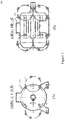
- Figure 2 shows a sectional view of axial magnetic field and a sectional view of radial magnetic field around the motor 110, in accordance with various embodiments of the present invention.
- the magnetic fields around the motor 110 can be categorized as axial magnetic field and radial magnetic field.
- the axial magnetic field is in a plan which includes the axis of the motor 110; it is generated by currents in the stator end windings or rotor cage end ring.
- the radial field is located in a plane perpendicular to the axis of the motor 110, it is an image of the air-gap flux density which is attenuated by the stator magnetic circuit (package of laminations) and by the frame of the motor 110.
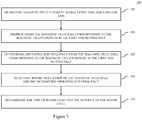
- Figure 3 illustrates a method 300 for condition monitoring, in accordance with various embodiments of the present invention.
- the magnetic field strength along a first axis and a second axis is measured using the triaxial magnetic field sensor.
- the triaxial magnetic field sensor transmits the measured magnetic field strength data (hereinafter referred to as magnetic field data) of the first axis and the second axis to the one or more processors.
- magnetic field data the measured magnetic field strength data
- measurement values above a predetermined threshold are recorded and transmitted by the triaxial magnetic field sensor to the one or more processors.
- the predetermined base threshold is decided by experimentation.
- the predetermined base threshold is determined during installation of the motor.
- the triaxial magnetic field sensor records and transmits magnetic field data upon receiving a signal from an accelerometer or a motor drive indicating that the motor 110 has been started.
- the one or more processors preprocess the magnetic field data.
- the one or more processors perform interpolation (linear, cubic or spline) to get an approximately equi-spaced and simultaneous magnetic field data of magnetic field strength from the first and second axes.
- interpolation linear, cubic or spline
- the magnetic field data is de-trended to remove static background magnetic flux and the drift experienced by the magnetic field sensors. De-trending is performed using techniques known in the art.
- the one or more processors determine the operating slip frequency from the de-trended magnetic field data corresponding to the magnetic field strength in the first and second axes.
- the de-trended magnetic field data of each axis in the time domain is converted to frequency spectrum in frequency domain using a fast Fourier transform.
- the one or more processors perform peak detection within a predetermined range in the first frequency spectrum corresponding to the first axis and the second frequency spectrum of the second axis to detect the frequency having the maximum amplitude. Peak detection is performed one or more techniques well known in the art such as least square curve fitting etc.
- the operating slip frequency would lie in in between nominal slip*(line frequency+1%) and 0 hertz (at no load situation).
- the largest peak within the predetermined range is indicative of the value of the operating slip frequency.
- the one or more processors detect the rotor fault based on the de-trended magnetic field data and the determined operating slip frequency. Subsequent to the detection of the operating slip frequency, the one or more processors calculates the average of the amplitude of the operating slip frequency in the first axis and the amplitude of the operating slip frequency in the second axis.
- the calculated average is compared with a predetermined value to detect whether a fault exists in the rotor.
- the predetermined value is the product of the cumulative averages of the signals in each axis and a predetermined constant.
- the one or more processor determine that the rotor is healthy. This essentially means that imbalance between the magnetic field along the first axis and the magnetic field along the second axis is low.
- the one or more processor determine that the rotor is faulty. This essentially means that imbalance between the magnetic field along the first axis and the magnetic field along the second axis is high. This is further explained in the description of figure 4 .
- the one or more processors determine the type of the detected fault and severity of the fault.
- a broken rotor bar fault is indicated.
- the magnitude of the operating slip frequency in the first axis i.e. axial magnetic field is less than the magnitude of the operating slip frequency in the second axis i.e. radial magnetic field
- a rotor misalignment fault is indicated.
- the severity of the fault is calculated as the percentage of unbalance between the peak magnitude or amplitude of the operating slip frequency in the radial and axial field.
- the data analysis unit 120 measures magnetic field strength along a third axis and generates a third frequency spectrum from the measured magnetic field strength along the third axis. Then the data analysis unit 120 identifies a peak within the predetermined range in the third frequency spectrum, and determines a frequency corresponding to the identified peak. Finally, the data analysis unit 120 compares the determined frequency against the determined operating slip frequency for detecting fault in a magnetic field sensor from the one or more magnetic field sensors. In case the determined frequency is not substantially similar to the determined operating slip frequency, the data analysis unit 120 transmits a warning to the remote service device 130 to indicate that a magnetic field sensor is faulty or is not calibrated properly.
- Figures 4 illustrates a spectrum of magnetic field in the first axis (shown with a continuous line) and second axis (shown with a short dashed line) of a healthy electric machine and a spectrum of magnetic field in the first axis and second axis of an electric machine with rotor bar fault, in accordance with various embodiments of the present invention.
- lines 410 and 420 indicate the upper limit of the predetermined range within which the operating slip frequency lies.
- the peak indicative of the operating slip frequency within the predetermined range is indicated by circle 415 in the healthy motor, and circle 425 in the second axis and circle 427 in the first axis in a faulty motor.
- the amplitude of the operating slip frequency in the first and second axis is relatively close to the floor (i.e. average) of the spectrum.
- the amplitude of the operating slip frequency in the first and second axis is relatively distant from the floor (i.e. average) of the spectrum.
- the current invention discloses a portable unit, movable with freedom with respect to the motor 110, for example in linear movement, in circular movement, in forward and backward movement, and so on.
- the portable unit can be any device, such as a mobile phone and other electronics devices; having a processing unit and magnetic field sensor embedded in the potable unit to distinguish healthy machine from the one with broken rotor bar or rotor misalignment, by that no additional hardware except mobile phone is required.
- the magnetic field sensor integrated therein can measure magnetic field intensity at least one of a plurality point of a path of the portable unit's free movement, and the skilled person should understand that any path consists of a multiple of points linking together.
- the processing unit can receive at least one corresponding magnetic field intensity signal from the magnetic sensor, compare at least one magnetic field intensity value to at least one corresponding expected value, and determining, based on the comparison, if a fault is present in the electric machine.
- Figure 5 illustrates a path in which the portable unit according to an embodiment of present invention moves with respective to the electric machine.
- the path 30 consists of a multiple of points linking together.
- a first point 31 of the multiple of points of the path is located in the area where an axial magnetic field is present around the electric machine;
- a second point 32 of the multiple points of the path of is located in area where a radial magnetic field is present around the electric machine.
- the portable unit 10 can move to the first point 31 or the second point 32 from another point along the path 30, or can move between the first point 31 and the second point 32 along the path 30.
- first point 31 and 50 the second point 32 are only for example indicating locations in the areas of an axial magnetic field and a radial magnetic field, and the path 30 is for example of the possible route of the portable unit.
- the skilled person should understand that there is some area of the electric machine on which it is difficult to install sensors, for example in the space between the end of the rotor and the stator, or where it is difficult to install the magnetic field sensor on the output end of the rotor where the output end of the rotor is mechanically linked to a shaft. It is easier to move the portable unit into such place and measure the rotor magnetic field leakage therein.
- the magnetic field sensor 11 integrated in the portable unit 10 can measure the axial magnetic field intensity for axial magnetic field at the first point 31 or measure the radial magnetic field intensity for radial magnetic field at the second point 32.
- the processing unit 12 integrated in the portable unit 10 can receive the magnetic field intensity signal representing the axial magnetic field leakage at the first point 31 from the magnetic field sensor 11 integrated in the portable unit 10, and/or receive the magnetic field intensity signal representing the radial magnetic field leakage at the first point 32 from the magnetic field sensor 11 integrated in the portable unit 10, and can compare the received magnetic field intensity value to expected value and determine based on the comparison if a fault is present in the electric machine.
- condition monitoring of electric machine the operator simply has to install the data analysis unit 120 on frame of the motor, akin to the name plate. Besides, it makes the result more accurate by condition monitoring electric machine's magnetic field directly and determining the electric machine's condition accordingly.
- By measuring magnetic field instead of current or vibration not only whole analysis can be performed just with the condition monitoring system but by measuring magnetic field the root of the problem is measured directly.
Landscapes
- Physics & Mathematics (AREA)
- General Physics & Mathematics (AREA)
- Tests Of Circuit Breakers, Generators, And Electric Motors (AREA)
Priority Applications (1)
| Application Number | Priority Date | Filing Date | Title |
|---|---|---|---|
| PL15714035T PL3143418T3 (pl) | 2014-05-15 | 2015-03-24 | Sposób i system wykrywania uszkodzeń wirnika |
Applications Claiming Priority (2)
| Application Number | Priority Date | Filing Date | Title |
|---|---|---|---|
| PCT/EP2014/059994 WO2015101422A1 (en) | 2013-12-30 | 2014-05-15 | System for condition monitoring of electric machine, mobile phone and method thereof |
| PCT/IB2015/052132 WO2015173662A1 (en) | 2014-05-15 | 2015-03-24 | Method and system for detecting rotor fault |
Publications (2)
| Publication Number | Publication Date |
|---|---|
| EP3143418A1 EP3143418A1 (en) | 2017-03-22 |
| EP3143418B1 true EP3143418B1 (en) | 2018-06-06 |
Family
ID=52808091
Family Applications (1)
| Application Number | Title | Priority Date | Filing Date |
|---|---|---|---|
| EP15714035.1A Active EP3143418B1 (en) | 2014-05-15 | 2015-03-24 | Method and system for detecting rotor fault |
Country Status (3)
| Country | Link |
|---|---|
| EP (1) | EP3143418B1 (pl) |
| PL (1) | PL3143418T3 (pl) |
| WO (1) | WO2015173662A1 (pl) |
Cited By (1)
| Publication number | Priority date | Publication date | Assignee | Title |
|---|---|---|---|---|
| US20220341977A1 (en) * | 2021-04-27 | 2022-10-27 | Kaeser Kompressoren Se | Method for contactless determination of an operating state |
Families Citing this family (10)
| Publication number | Priority date | Publication date | Assignee | Title |
|---|---|---|---|---|
| WO2017075254A1 (en) * | 2015-10-30 | 2017-05-04 | Faraday&Future Inc. | Interior magnet machine design with low core losses |
| CN106706028B (zh) * | 2015-11-13 | 2021-03-02 | Abb技术有限公司 | 用于检测电机状态的方法和系统 |
| CN205992042U (zh) * | 2016-07-22 | 2017-03-01 | Abb 瑞士有限公司 | 用于监测电机的状态监测装置 |
| CN107764316A (zh) * | 2016-08-23 | 2018-03-06 | Abb 瑞士有限公司 | 用于监测多个马达的状况的系统 |
| EP3623828A1 (en) | 2018-09-14 | 2020-03-18 | Hitech & Development Wireless Sweden AB | Machine operation monitoring |
| WO2021019436A1 (en) * | 2019-07-31 | 2021-02-04 | Abb Schweiz Ag | A method and device for estimating running speed of a rotating equipment |
| GB201914844D0 (en) | 2019-10-14 | 2019-11-27 | Norwegian Univ Sci & Tech Ntnu | Fault detection in synchronous machines |
| CN112782580B (zh) * | 2021-02-25 | 2023-02-10 | 上海弈格工程技术有限公司 | 一种电机的故障评估系统 |
| JP2024519199A (ja) | 2021-04-27 | 2024-05-09 | カエザー・コンプレソーレン・エスエー | 動作状態を非接触で確認するための方法 |
| CN114942385B (zh) * | 2022-06-24 | 2025-09-02 | 郑州恩普特科技股份有限公司 | 一种电机转速估算方法及系统 |
Family Cites Families (2)
| Publication number | Priority date | Publication date | Assignee | Title |
|---|---|---|---|---|
| US5049815A (en) * | 1990-04-20 | 1991-09-17 | General Electric Company | Spectral analysis of induction motor current to detect rotor faults with reduced false alarms |
| US5519337A (en) * | 1993-11-04 | 1996-05-21 | Martin Marietta Energy Systems, Inc. | Motor monitoring method and apparatus using high frequency current components |
-
2015
- 2015-03-24 PL PL15714035T patent/PL3143418T3/pl unknown
- 2015-03-24 WO PCT/IB2015/052132 patent/WO2015173662A1/en not_active Ceased
- 2015-03-24 EP EP15714035.1A patent/EP3143418B1/en active Active
Non-Patent Citations (1)
| Title |
|---|
| None * |
Cited By (2)
| Publication number | Priority date | Publication date | Assignee | Title |
|---|---|---|---|---|
| US20220341977A1 (en) * | 2021-04-27 | 2022-10-27 | Kaeser Kompressoren Se | Method for contactless determination of an operating state |
| US12061220B2 (en) * | 2021-04-27 | 2024-08-13 | Kaeser Kompressoren Se | Method for contactless determination of an operating state |
Also Published As
| Publication number | Publication date |
|---|---|
| EP3143418A1 (en) | 2017-03-22 |
| PL3143418T3 (pl) | 2018-11-30 |
| WO2015173662A1 (en) | 2015-11-19 |
Similar Documents
| Publication | Publication Date | Title |
|---|---|---|
| US10353004B2 (en) | Method and system for detecting rotor fault using triaxial magnetic field sensor | |
| WO2015173662A1 (en) | Method and system for detecting rotor fault | |
| US9823308B2 (en) | Method for monitoring demagnetization | |
| AU2017100471B4 (en) | A condition monitoring device for monitoring an electric machine | |
| EP2919027A1 (en) | Fault detection in induction machines | |
| US10408879B2 (en) | Method and apparatus for diagnosing a fault condition in an electric machine | |
| CN106304846B (zh) | 用于确定同步机故障状态的方法和系统 | |
| US9255837B2 (en) | Method for identifying a fault in an electrical machine | |
| US20150276823A1 (en) | Method For Detecting A Fault Condition In An Electrical Machine | |
| EP3054307A1 (en) | Stator fault detection and diagnosis | |
| Kunthong et al. | IoT-based traction motor drive condition monitoring in electric vehicles: Part 1 | |
| JP2013101030A (ja) | トルク測定装置 | |
| EP2933647A1 (en) | A model based diagnostic of induction machine | |
| JP2007315994A (ja) | 回転電機の温度変化検知方法およびその装置 | |
| CN103314302B (zh) | 增强旋转电机上的发电机接地故障检测的可靠性的方法和设备 | |
| TW202009498A (zh) | 電氣機械的診斷裝置及診斷方法、以及旋轉電機 | |
| EP3168631A1 (en) | Method and system for detecting a condition of an electric machine | |
| CN108151795B (zh) | 用于配置状态监测装置的方法及系统 | |
| RU2716172C2 (ru) | Способ диагностики асинхронных двигателей с короткозамкнутым ротором | |
| CN109425828A (zh) | 马达特性检测方法 | |
| KR102125753B1 (ko) | 전기 구동 장치에서 벤딩 효과의 검출 방법 |
Legal Events
| Date | Code | Title | Description |
|---|---|---|---|
| STAA | Information on the status of an ep patent application or granted ep patent |
Free format text: STATUS: THE INTERNATIONAL PUBLICATION HAS BEEN MADE |
|
| PUAI | Public reference made under article 153(3) epc to a published international application that has entered the european phase |
Free format text: ORIGINAL CODE: 0009012 |
|
| STAA | Information on the status of an ep patent application or granted ep patent |
Free format text: STATUS: REQUEST FOR EXAMINATION WAS MADE |
|
| 17P | Request for examination filed |
Effective date: 20161117 |
|
| AK | Designated contracting states |
Kind code of ref document: A1 Designated state(s): AL AT BE BG CH CY CZ DE DK EE ES FI FR GB GR HR HU IE IS IT LI LT LU LV MC MK MT NL NO PL PT RO RS SE SI SK SM TR |
|
| AX | Request for extension of the european patent |
Extension state: BA ME |
|
| DAV | Request for validation of the european patent (deleted) | ||
| DAX | Request for extension of the european patent (deleted) | ||
| GRAP | Despatch of communication of intention to grant a patent |
Free format text: ORIGINAL CODE: EPIDOSNIGR1 |
|
| STAA | Information on the status of an ep patent application or granted ep patent |
Free format text: STATUS: GRANT OF PATENT IS INTENDED |
|
| INTG | Intention to grant announced |
Effective date: 20171026 |
|
| GRAS | Grant fee paid |
Free format text: ORIGINAL CODE: EPIDOSNIGR3 |
|
| GRAA | (expected) grant |
Free format text: ORIGINAL CODE: 0009210 |
|
| STAA | Information on the status of an ep patent application or granted ep patent |
Free format text: STATUS: THE PATENT HAS BEEN GRANTED |
|
| AK | Designated contracting states |
Kind code of ref document: B1 Designated state(s): AL AT BE BG CH CY CZ DE DK EE ES FI FR GB GR HR HU IE IS IT LI LT LU LV MC MK MT NL NO PL PT RO RS SE SI SK SM TR |
|
| REG | Reference to a national code |
Ref country code: GB Ref legal event code: FG4D |
|
| REG | Reference to a national code |
Ref country code: CH Ref legal event code: EP Ref country code: AT Ref legal event code: REF Ref document number: 1006700 Country of ref document: AT Kind code of ref document: T Effective date: 20180615 |
|
| REG | Reference to a national code |
Ref country code: IE Ref legal event code: FG4D |
|
| REG | Reference to a national code |
Ref country code: DE Ref legal event code: R096 Ref document number: 602015011853 Country of ref document: DE |
|
| REG | Reference to a national code |
Ref country code: ES Ref legal event code: FG2A Ref document number: 2682951 Country of ref document: ES Kind code of ref document: T3 Effective date: 20180924 |
|
| REG | Reference to a national code |
Ref country code: NL Ref legal event code: MP Effective date: 20180606 |
|
| REG | Reference to a national code |
Ref country code: LT Ref legal event code: MG4D |
|
| PG25 | Lapsed in a contracting state [announced via postgrant information from national office to epo] |
Ref country code: LT Free format text: LAPSE BECAUSE OF FAILURE TO SUBMIT A TRANSLATION OF THE DESCRIPTION OR TO PAY THE FEE WITHIN THE PRESCRIBED TIME-LIMIT Effective date: 20180606 Ref country code: NO Free format text: LAPSE BECAUSE OF FAILURE TO SUBMIT A TRANSLATION OF THE DESCRIPTION OR TO PAY THE FEE WITHIN THE PRESCRIBED TIME-LIMIT Effective date: 20180906 Ref country code: BG Free format text: LAPSE BECAUSE OF FAILURE TO SUBMIT A TRANSLATION OF THE DESCRIPTION OR TO PAY THE FEE WITHIN THE PRESCRIBED TIME-LIMIT Effective date: 20180906 Ref country code: CY Free format text: LAPSE BECAUSE OF FAILURE TO SUBMIT A TRANSLATION OF THE DESCRIPTION OR TO PAY THE FEE WITHIN THE PRESCRIBED TIME-LIMIT Effective date: 20180606 Ref country code: SE Free format text: LAPSE BECAUSE OF FAILURE TO SUBMIT A TRANSLATION OF THE DESCRIPTION OR TO PAY THE FEE WITHIN THE PRESCRIBED TIME-LIMIT Effective date: 20180606 |
|
| PG25 | Lapsed in a contracting state [announced via postgrant information from national office to epo] |
Ref country code: GR Free format text: LAPSE BECAUSE OF FAILURE TO SUBMIT A TRANSLATION OF THE DESCRIPTION OR TO PAY THE FEE WITHIN THE PRESCRIBED TIME-LIMIT Effective date: 20180907 Ref country code: RS Free format text: LAPSE BECAUSE OF FAILURE TO SUBMIT A TRANSLATION OF THE DESCRIPTION OR TO PAY THE FEE WITHIN THE PRESCRIBED TIME-LIMIT Effective date: 20180606 Ref country code: LV Free format text: LAPSE BECAUSE OF FAILURE TO SUBMIT A TRANSLATION OF THE DESCRIPTION OR TO PAY THE FEE WITHIN THE PRESCRIBED TIME-LIMIT Effective date: 20180606 Ref country code: HR Free format text: LAPSE BECAUSE OF FAILURE TO SUBMIT A TRANSLATION OF THE DESCRIPTION OR TO PAY THE FEE WITHIN THE PRESCRIBED TIME-LIMIT Effective date: 20180606 |
|
| REG | Reference to a national code |
Ref country code: AT Ref legal event code: MK05 Ref document number: 1006700 Country of ref document: AT Kind code of ref document: T Effective date: 20180606 |
|
| PG25 | Lapsed in a contracting state [announced via postgrant information from national office to epo] |
Ref country code: NL Free format text: LAPSE BECAUSE OF FAILURE TO SUBMIT A TRANSLATION OF THE DESCRIPTION OR TO PAY THE FEE WITHIN THE PRESCRIBED TIME-LIMIT Effective date: 20180606 |
|
| PG25 | Lapsed in a contracting state [announced via postgrant information from national office to epo] |
Ref country code: SK Free format text: LAPSE BECAUSE OF FAILURE TO SUBMIT A TRANSLATION OF THE DESCRIPTION OR TO PAY THE FEE WITHIN THE PRESCRIBED TIME-LIMIT Effective date: 20180606 Ref country code: AT Free format text: LAPSE BECAUSE OF FAILURE TO SUBMIT A TRANSLATION OF THE DESCRIPTION OR TO PAY THE FEE WITHIN THE PRESCRIBED TIME-LIMIT Effective date: 20180606 Ref country code: EE Free format text: LAPSE BECAUSE OF FAILURE TO SUBMIT A TRANSLATION OF THE DESCRIPTION OR TO PAY THE FEE WITHIN THE PRESCRIBED TIME-LIMIT Effective date: 20180606 Ref country code: IS Free format text: LAPSE BECAUSE OF FAILURE TO SUBMIT A TRANSLATION OF THE DESCRIPTION OR TO PAY THE FEE WITHIN THE PRESCRIBED TIME-LIMIT Effective date: 20181006 Ref country code: RO Free format text: LAPSE BECAUSE OF FAILURE TO SUBMIT A TRANSLATION OF THE DESCRIPTION OR TO PAY THE FEE WITHIN THE PRESCRIBED TIME-LIMIT Effective date: 20180606 |
|
| PG25 | Lapsed in a contracting state [announced via postgrant information from national office to epo] |
Ref country code: SM Free format text: LAPSE BECAUSE OF FAILURE TO SUBMIT A TRANSLATION OF THE DESCRIPTION OR TO PAY THE FEE WITHIN THE PRESCRIBED TIME-LIMIT Effective date: 20180606 |
|
| REG | Reference to a national code |
Ref country code: DE Ref legal event code: R097 Ref document number: 602015011853 Country of ref document: DE |
|
| PLBE | No opposition filed within time limit |
Free format text: ORIGINAL CODE: 0009261 |
|
| STAA | Information on the status of an ep patent application or granted ep patent |
Free format text: STATUS: NO OPPOSITION FILED WITHIN TIME LIMIT |
|
| 26N | No opposition filed |
Effective date: 20190307 |
|
| PG25 | Lapsed in a contracting state [announced via postgrant information from national office to epo] |
Ref country code: DK Free format text: LAPSE BECAUSE OF FAILURE TO SUBMIT A TRANSLATION OF THE DESCRIPTION OR TO PAY THE FEE WITHIN THE PRESCRIBED TIME-LIMIT Effective date: 20180606 Ref country code: SI Free format text: LAPSE BECAUSE OF FAILURE TO SUBMIT A TRANSLATION OF THE DESCRIPTION OR TO PAY THE FEE WITHIN THE PRESCRIBED TIME-LIMIT Effective date: 20180606 |
|
| PG25 | Lapsed in a contracting state [announced via postgrant information from national office to epo] |
Ref country code: MC Free format text: LAPSE BECAUSE OF FAILURE TO SUBMIT A TRANSLATION OF THE DESCRIPTION OR TO PAY THE FEE WITHIN THE PRESCRIBED TIME-LIMIT Effective date: 20180606 |
|
| REG | Reference to a national code |
Ref country code: CH Ref legal event code: PL |
|
| PG25 | Lapsed in a contracting state [announced via postgrant information from national office to epo] |
Ref country code: LU Free format text: LAPSE BECAUSE OF NON-PAYMENT OF DUE FEES Effective date: 20190324 Ref country code: AL Free format text: LAPSE BECAUSE OF FAILURE TO SUBMIT A TRANSLATION OF THE DESCRIPTION OR TO PAY THE FEE WITHIN THE PRESCRIBED TIME-LIMIT Effective date: 20180606 |
|
| REG | Reference to a national code |
Ref country code: BE Ref legal event code: MM Effective date: 20190331 |
|
| PG25 | Lapsed in a contracting state [announced via postgrant information from national office to epo] |
Ref country code: IE Free format text: LAPSE BECAUSE OF NON-PAYMENT OF DUE FEES Effective date: 20190324 Ref country code: LI Free format text: LAPSE BECAUSE OF NON-PAYMENT OF DUE FEES Effective date: 20190331 Ref country code: CH Free format text: LAPSE BECAUSE OF NON-PAYMENT OF DUE FEES Effective date: 20190331 |
|
| PG25 | Lapsed in a contracting state [announced via postgrant information from national office to epo] |
Ref country code: BE Free format text: LAPSE BECAUSE OF NON-PAYMENT OF DUE FEES Effective date: 20190331 |
|
| PG25 | Lapsed in a contracting state [announced via postgrant information from national office to epo] |
Ref country code: TR Free format text: LAPSE BECAUSE OF FAILURE TO SUBMIT A TRANSLATION OF THE DESCRIPTION OR TO PAY THE FEE WITHIN THE PRESCRIBED TIME-LIMIT Effective date: 20180606 |
|
| PG25 | Lapsed in a contracting state [announced via postgrant information from national office to epo] |
Ref country code: PT Free format text: LAPSE BECAUSE OF FAILURE TO SUBMIT A TRANSLATION OF THE DESCRIPTION OR TO PAY THE FEE WITHIN THE PRESCRIBED TIME-LIMIT Effective date: 20181008 Ref country code: MT Free format text: LAPSE BECAUSE OF NON-PAYMENT OF DUE FEES Effective date: 20190324 |
|
| PG25 | Lapsed in a contracting state [announced via postgrant information from national office to epo] |
Ref country code: HU Free format text: LAPSE BECAUSE OF FAILURE TO SUBMIT A TRANSLATION OF THE DESCRIPTION OR TO PAY THE FEE WITHIN THE PRESCRIBED TIME-LIMIT; INVALID AB INITIO Effective date: 20150324 |
|
| PG25 | Lapsed in a contracting state [announced via postgrant information from national office to epo] |
Ref country code: MK Free format text: LAPSE BECAUSE OF FAILURE TO SUBMIT A TRANSLATION OF THE DESCRIPTION OR TO PAY THE FEE WITHIN THE PRESCRIBED TIME-LIMIT Effective date: 20180606 |
|
| PGFP | Annual fee paid to national office [announced via postgrant information from national office to epo] |
Ref country code: ES Payment date: 20250429 Year of fee payment: 11 |
|
| PGFP | Annual fee paid to national office [announced via postgrant information from national office to epo] |
Ref country code: GB Payment date: 20260324 Year of fee payment: 12 |
|
| PGFP | Annual fee paid to national office [announced via postgrant information from national office to epo] |
Ref country code: DE Payment date: 20260319 Year of fee payment: 12 |
|
| PGFP | Annual fee paid to national office [announced via postgrant information from national office to epo] |
Ref country code: FI Payment date: 20260323 Year of fee payment: 12 Ref country code: IT Payment date: 20260324 Year of fee payment: 12 |
|
| PGFP | Annual fee paid to national office [announced via postgrant information from national office to epo] |
Ref country code: FR Payment date: 20260320 Year of fee payment: 12 |
|
| PGFP | Annual fee paid to national office [announced via postgrant information from national office to epo] |
Ref country code: CZ Payment date: 20260320 Year of fee payment: 12 |
|
| PGFP | Annual fee paid to national office [announced via postgrant information from national office to epo] |
Ref country code: PL Payment date: 20260313 Year of fee payment: 12 |