EP3143324B1 - Leuchte mit fester winkelposition und lampenmodul für leuchten - Google Patents
Leuchte mit fester winkelposition und lampenmodul für leuchten Download PDFInfo
- Publication number
- EP3143324B1 EP3143324B1 EP15792109.9A EP15792109A EP3143324B1 EP 3143324 B1 EP3143324 B1 EP 3143324B1 EP 15792109 A EP15792109 A EP 15792109A EP 3143324 B1 EP3143324 B1 EP 3143324B1
- Authority
- EP
- European Patent Office
- Prior art keywords
- bracket
- light
- light fixture
- housing
- wall
- Prior art date
- Legal status (The legal status is an assumption and is not a legal conclusion. Google has not performed a legal analysis and makes no representation as to the accuracy of the status listed.)
- Active
Links
- 239000004020 conductor Substances 0.000 claims description 23
- 230000013011 mating Effects 0.000 claims description 13
- 239000000463 material Substances 0.000 description 5
- 230000001154 acute effect Effects 0.000 description 4
- 229920000642 polymer Polymers 0.000 description 4
- 229920001296 polysiloxane Polymers 0.000 description 4
- WYVBETQIUHPLFO-UHFFFAOYSA-N 1,2-dichloro-4-(2,6-dichlorophenyl)benzene Chemical compound C1=C(Cl)C(Cl)=CC=C1C1=C(Cl)C=CC=C1Cl WYVBETQIUHPLFO-UHFFFAOYSA-N 0.000 description 3
- 239000002861 polymer material Substances 0.000 description 3
- 230000007704 transition Effects 0.000 description 3
- 229910052782 aluminium Inorganic materials 0.000 description 2
- XAGFODPZIPBFFR-UHFFFAOYSA-N aluminium Chemical compound [Al] XAGFODPZIPBFFR-UHFFFAOYSA-N 0.000 description 2
- 239000002131 composite material Substances 0.000 description 2
- 229920001971 elastomer Polymers 0.000 description 2
- 239000000806 elastomer Substances 0.000 description 2
- 238000001125 extrusion Methods 0.000 description 2
- 238000003754 machining Methods 0.000 description 2
- 229910052751 metal Inorganic materials 0.000 description 2
- 239000007769 metal material Substances 0.000 description 2
- 238000000034 method Methods 0.000 description 2
- 238000000465 moulding Methods 0.000 description 2
- 239000000853 adhesive Substances 0.000 description 1
- 230000001070 adhesive effect Effects 0.000 description 1
- 238000004519 manufacturing process Methods 0.000 description 1
- 238000012986 modification Methods 0.000 description 1
- 230000004048 modification Effects 0.000 description 1
- 230000037361 pathway Effects 0.000 description 1
- 229920003229 poly(methyl methacrylate) Polymers 0.000 description 1
- 239000004417 polycarbonate Substances 0.000 description 1
- 229920000515 polycarbonate Polymers 0.000 description 1
- 239000004926 polymethyl methacrylate Substances 0.000 description 1
- 230000000717 retained effect Effects 0.000 description 1
- 239000007787 solid Substances 0.000 description 1
Images


Classifications
-
- F—MECHANICAL ENGINEERING; LIGHTING; HEATING; WEAPONS; BLASTING
- F21—LIGHTING
- F21V—FUNCTIONAL FEATURES OR DETAILS OF LIGHTING DEVICES OR SYSTEMS THEREOF; STRUCTURAL COMBINATIONS OF LIGHTING DEVICES WITH OTHER ARTICLES, NOT OTHERWISE PROVIDED FOR
- F21V13/00—Producing particular characteristics or distribution of the light emitted by means of a combination of elements specified in two or more of main groups F21V1/00 - F21V11/00
- F21V13/12—Combinations of only three kinds of elements
-
- F—MECHANICAL ENGINEERING; LIGHTING; HEATING; WEAPONS; BLASTING
- F21—LIGHTING
- F21S—NON-PORTABLE LIGHTING DEVICES; SYSTEMS THEREOF; VEHICLE LIGHTING DEVICES SPECIALLY ADAPTED FOR VEHICLE EXTERIORS
- F21S2/00—Systems of lighting devices, not provided for in main groups F21S4/00 - F21S10/00 or F21S19/00, e.g. of modular construction
- F21S2/005—Systems of lighting devices, not provided for in main groups F21S4/00 - F21S10/00 or F21S19/00, e.g. of modular construction of modular construction
-
- F—MECHANICAL ENGINEERING; LIGHTING; HEATING; WEAPONS; BLASTING
- F21—LIGHTING
- F21S—NON-PORTABLE LIGHTING DEVICES; SYSTEMS THEREOF; VEHICLE LIGHTING DEVICES SPECIALLY ADAPTED FOR VEHICLE EXTERIORS
- F21S8/00—Lighting devices intended for fixed installation
- F21S8/08—Lighting devices intended for fixed installation with a standard
- F21S8/085—Lighting devices intended for fixed installation with a standard of high-built type, e.g. street light
- F21S8/086—Lighting devices intended for fixed installation with a standard of high-built type, e.g. street light with lighting device attached sideways of the standard, e.g. for roads and highways
-
- F—MECHANICAL ENGINEERING; LIGHTING; HEATING; WEAPONS; BLASTING
- F21—LIGHTING
- F21S—NON-PORTABLE LIGHTING DEVICES; SYSTEMS THEREOF; VEHICLE LIGHTING DEVICES SPECIALLY ADAPTED FOR VEHICLE EXTERIORS
- F21S8/00—Lighting devices intended for fixed installation
- F21S8/08—Lighting devices intended for fixed installation with a standard
- F21S8/085—Lighting devices intended for fixed installation with a standard of high-built type, e.g. street light
- F21S8/088—Lighting devices intended for fixed installation with a standard of high-built type, e.g. street light with lighting device mounted on top of the standard, e.g. for pedestrian zones
-
- F—MECHANICAL ENGINEERING; LIGHTING; HEATING; WEAPONS; BLASTING
- F21—LIGHTING
- F21V—FUNCTIONAL FEATURES OR DETAILS OF LIGHTING DEVICES OR SYSTEMS THEREOF; STRUCTURAL COMBINATIONS OF LIGHTING DEVICES WITH OTHER ARTICLES, NOT OTHERWISE PROVIDED FOR
- F21V11/00—Screens not covered by groups F21V1/00, F21V3/00, F21V7/00 or F21V9/00
- F21V11/16—Screens not covered by groups F21V1/00, F21V3/00, F21V7/00 or F21V9/00 using sheets without apertures, e.g. fixed
-
- F—MECHANICAL ENGINEERING; LIGHTING; HEATING; WEAPONS; BLASTING
- F21—LIGHTING
- F21V—FUNCTIONAL FEATURES OR DETAILS OF LIGHTING DEVICES OR SYSTEMS THEREOF; STRUCTURAL COMBINATIONS OF LIGHTING DEVICES WITH OTHER ARTICLES, NOT OTHERWISE PROVIDED FOR
- F21V19/00—Fastening of light sources or lamp holders
- F21V19/001—Fastening of light sources or lamp holders the light sources being semiconductors devices, e.g. LEDs
- F21V19/0015—Fastening arrangements intended to retain light sources
- F21V19/002—Fastening arrangements intended to retain light sources the fastening means engaging the encapsulation or the packaging of the semiconductor device
-
- F—MECHANICAL ENGINEERING; LIGHTING; HEATING; WEAPONS; BLASTING
- F21—LIGHTING
- F21V—FUNCTIONAL FEATURES OR DETAILS OF LIGHTING DEVICES OR SYSTEMS THEREOF; STRUCTURAL COMBINATIONS OF LIGHTING DEVICES WITH OTHER ARTICLES, NOT OTHERWISE PROVIDED FOR
- F21V5/00—Refractors for light sources
- F21V5/04—Refractors for light sources of lens shape
-
- F—MECHANICAL ENGINEERING; LIGHTING; HEATING; WEAPONS; BLASTING
- F21—LIGHTING
- F21V—FUNCTIONAL FEATURES OR DETAILS OF LIGHTING DEVICES OR SYSTEMS THEREOF; STRUCTURAL COMBINATIONS OF LIGHTING DEVICES WITH OTHER ARTICLES, NOT OTHERWISE PROVIDED FOR
- F21V7/00—Reflectors for light sources
- F21V7/0066—Reflectors for light sources specially adapted to cooperate with point like light sources; specially adapted to cooperate with light sources the shape of which is unspecified
-
- F—MECHANICAL ENGINEERING; LIGHTING; HEATING; WEAPONS; BLASTING
- F21—LIGHTING
- F21K—NON-ELECTRIC LIGHT SOURCES USING LUMINESCENCE; LIGHT SOURCES USING ELECTROCHEMILUMINESCENCE; LIGHT SOURCES USING CHARGES OF COMBUSTIBLE MATERIAL; LIGHT SOURCES USING SEMICONDUCTOR DEVICES AS LIGHT-GENERATING ELEMENTS; LIGHT SOURCES NOT OTHERWISE PROVIDED FOR
- F21K9/00—Light sources using semiconductor devices as light-generating elements, e.g. using light-emitting diodes [LED] or lasers
- F21K9/20—Light sources comprising attachment means
-
- F—MECHANICAL ENGINEERING; LIGHTING; HEATING; WEAPONS; BLASTING
- F21—LIGHTING
- F21V—FUNCTIONAL FEATURES OR DETAILS OF LIGHTING DEVICES OR SYSTEMS THEREOF; STRUCTURAL COMBINATIONS OF LIGHTING DEVICES WITH OTHER ARTICLES, NOT OTHERWISE PROVIDED FOR
- F21V7/00—Reflectors for light sources
- F21V7/0091—Reflectors for light sources using total internal reflection
-
- F—MECHANICAL ENGINEERING; LIGHTING; HEATING; WEAPONS; BLASTING
- F21—LIGHTING
- F21W—INDEXING SCHEME ASSOCIATED WITH SUBCLASSES F21K, F21L, F21S and F21V, RELATING TO USES OR APPLICATIONS OF LIGHTING DEVICES OR SYSTEMS
- F21W2131/00—Use or application of lighting devices or systems not provided for in codes F21W2102/00-F21W2121/00
- F21W2131/10—Outdoor lighting
- F21W2131/103—Outdoor lighting of streets or roads
-
- F—MECHANICAL ENGINEERING; LIGHTING; HEATING; WEAPONS; BLASTING
- F21—LIGHTING
- F21Y—INDEXING SCHEME ASSOCIATED WITH SUBCLASSES F21K, F21L, F21S and F21V, RELATING TO THE FORM OR THE KIND OF THE LIGHT SOURCES OR OF THE COLOUR OF THE LIGHT EMITTED
- F21Y2103/00—Elongate light sources, e.g. fluorescent tubes
- F21Y2103/10—Elongate light sources, e.g. fluorescent tubes comprising a linear array of point-like light-generating elements
-
- F—MECHANICAL ENGINEERING; LIGHTING; HEATING; WEAPONS; BLASTING
- F21—LIGHTING
- F21Y—INDEXING SCHEME ASSOCIATED WITH SUBCLASSES F21K, F21L, F21S and F21V, RELATING TO THE FORM OR THE KIND OF THE LIGHT SOURCES OR OF THE COLOUR OF THE LIGHT EMITTED
- F21Y2107/00—Light sources with three-dimensionally disposed light-generating elements
- F21Y2107/60—Light sources with three-dimensionally disposed light-generating elements on stacked substrates
-
- F—MECHANICAL ENGINEERING; LIGHTING; HEATING; WEAPONS; BLASTING
- F21—LIGHTING
- F21Y—INDEXING SCHEME ASSOCIATED WITH SUBCLASSES F21K, F21L, F21S and F21V, RELATING TO THE FORM OR THE KIND OF THE LIGHT SOURCES OR OF THE COLOUR OF THE LIGHT EMITTED
- F21Y2115/00—Light-generating elements of semiconductor light sources
- F21Y2115/10—Light-emitting diodes [LED]
Definitions
- Exemplary embodiments relate to light fixtures, for example external light fixtures designed to illuminate streets, paths, parking lots, or other areas.
- Light fixtures or luminaires, are used with electric light sources to provide aesthetic and functional housing in both interior and exterior applications.
- One type of light fixture is a street lamp, generally used for exterior lighting of roads, walkways, parks, parking lots, or other large areas requiring a significant amount of lighting. Street lamps typically include a light fixture attached to pole or post to provide an elevated lighting position.
- lighting applications including street lamps have trended towards the use of light emitting diodes (LEDs) as a light source in place of conventional incandescent and fluorescent lamps.
- the document EP 1 332 957 shows the preamble of claim 1 and discloses a vehicle provided with a taillight.
- the taillight includes a lens and a stepped base bent in a staircase pattern. A plurality of light-emitting diodes is mounted on such stepped base, almost parallel with the lens.
- Such lens forms a substantially hermetical space by being joined up with a case, which also has a stepped cross section.
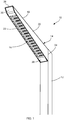
- a light fixture assembly 10 is connected to a support, for example a pole 12 extending vertically from the ground (not shown).
- the support may be any stable structure, such as a wall or a beam.
- the light fixture assembly 10 includes a housing 14 having a cavity for retaining one or more compartmentalized, recessed lamp units 16.
- the housing 14 extends from the pole 12 and includes a first end adjacent and connected to the pole 12 and a second end distal to the pole 12.
- the housing 14 extends obliquely from the pole 12, outwardly and away from the ground and emits light downwardly.
- the housing 14 and the lamp units 16 prevent light from being emitted in a direction parallel to the ground and/or above the light fixture relative to the ground.
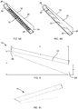
- the housing 14 includes a top 18, a first side 20, and a second side 22.
- the first and second sides 20, 22 extend from the top 18 toward the ground.
- a chamfered edge connects the first and second sides 20, 22 with the top 18.
- the first and second sides 20, 22 taper from a first height at a base 24 adjacent the pole to a second height at a tip 26 at the opposite end.
- the first and second sides 20, 22 have a bottom edge with a first section having a first angle of inclination relative to the post 12 and a second section having a second angle of inclination relative to the post greater than the first angle.
- the housing 14 includes a first end cap 28 and a second end cap 30 bordering the lamp units 16.
- An outer diffuser or lens 32 can be connected to the housing 14 as shown in FIG. 8B .
- FIGS. 9-10 illustrate an exemplary embodiment of the housing 14 configured to provide an angled transition from the pole 12 while preventing light from being emitted parallel to the ground and/or upward relative to the ground.
- the housing 14 has a top 18 with length A, an overall height B measured from the bottom of the base 24 to the top of the tip 26, an overall horizontal length C from the first end to the second end, a height D of the base 24, and the top 18 has a width E.
- the top width E is configured to be substantially the width of the pole 12. In an exemplary embodiment the top width E is approximately 4.0-5.0 inches.
- Dimension B is configured to have an approximately 0.4 ratio to dimension A
- dimension C is configured to have an approximately 0.98 ratio to dimension A
- dimension D is configured to have an approximately 0.18 ratio to dimension A.
- the housing 14 has different dimensions as indicated in table 1 where K4 represents an exemplary 4 inch wide luminaire and K5 represents an exemplary 5 inch wide luminaire: TABLE 1 K4 RATIO TO A K5 RATIO TO A A 34.084 41.084 B 13.7 0.40 16.106 0.39 C 33.24 0.98 40.031 0.97 D 6.03 0.18 6.864 0.17
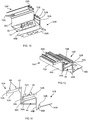
- a cavity within the housing 14 receives one or more modular lamp units 16.
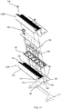
- the light fixture assembly 10 illustrated in FIGS. 11-14 includes a first bracket 34A, an LED board 36, a conductor grommet 38, one or more optics 40, a gasket 42, and a reflector 44.
- the first bracket 34A is configured to connect to a similar or identical second bracket 34B, for example through a mechanical connection such as a mating fit, an interference fit, or a snap fit.
- One or more mechanical fasteners 46 may be used to hold the first bracket 34A to the second bracket 34B and to secure one or more of the other elements in the lamp unit 16.
- brackets 34A, 34B mate to form a stair-like pattern where each additional bracket is spaced outwardly and above the previous bracket. In this way, a single lamp unit 16 may be manufactured and adapted for use with various sized light housings 14.
- similar parts on the brackets 34A, 34B are described and labeled only once. As necessary, similar parts of the brackets 34A, 34B are designated with the same number with either an A or a B designation.
- the bracket 34A includes a wall 48, a bottom member 50 extending from the wall 48 in a first direction and a top member 52 extending from the wall 48 in the second direction, giving the bracket 34A an approximately Z-shaped configuration.
- the bottom and top members 50, 52 are substantially rectangular plates.
- the bracket 34A is made from a rigid material, for example aluminum or other suitable metal, polymer, or composite material.
- the bracket 34A may be formed through machining, extrusions, molding, or other suitable processes.
- the wall 48 of the bracket 34A extends between the bottom member 50 and the top member 52.
- the wall 48 may be substantially vertical, orthogonal to the ground, or the wall 48 may have an angle of inclination relative to a vertical axis, for example between 0 and 10 degrees in either direction.
- the wall 48 has a front surface and a rear surface. The size, shape, and configuration of the wall 48 can be changed depending on the housing 12, the light source (not shown), and other design and utility considerations.
- the bottom member 50 extends obliquely from the bottom of the wall 48 in a first direction. In the exemplary embodiment shown, the bottom member 50 extends at an acute angle relative to the rear surface of the wall.
- the bottom member 50 has a first section with a first angle of inclination to the wall 48 and a second section with a second angle of inclination greater than the first angle of inclination relative to the wall 48.
- a first projection 54 extends from the bottom member 50 towards the top member 52 continuously along the width of the bottom member 50. In alternative embodiments, the height, shape, length, and position of the first projection 54 may vary according to the needs of the light source and the housing 14 and on the various types of required connections.
- the bottom member 50 includes one or more light apertures 58 for receiving a light source and/or an optic 40 associated with a light source.
- the bottom member 50 also includes one or more fastener apertures 60 for receiving a mechanical fastener 46.
- the exemplary embodiment shown in FIGS. 11-14 depicts two light apertures 58 and two fastener apertures 60.
- the size, shape, and configuration of the bottom member 50 may vary according to the light source, the housing 14, and other design and utility considerations.
- the top member 52 extends obliquely from the top of the wall 48 in the second direction. In the exemplary embodiment shown, the top member 52 extends at an acute angle relative to the front surface of the wall.
- One or more heat fins 62 extend from the top surface of the top member 52 to dissipate heat generated by the light source.
- a set of tines 64 also extend from the top surface of the top member 52 bounding a channel.
- the top member 52 includes a conductor aperture 68 to receive the conductor grommet 38 and one or more fastener openings 69 to receive a mechanical fastener 46.
- the conductor aperture 68 allows conductors to pass through the top member 52 and connect to the LED board 36.
- the conductor grommet 38 protects the conductor passing through the bracket 34A from wear.
- the conductor grommet 38 may be made from a suitable polymer or elastomer material, for example silicone.
- a second projection 70 extends from the top member 52 in the direction of the bottom member 50. The second projection 70 is configured to mate with the groove 56 and/or the first projection 54 of the bottom member 50 to form a connection with an identical or similarly configured bracket 34B.
- the LED board 36 contains a printed circuit board (PCB) 71 and one or more light sources (not shown), for example LED light sources.
- the PCB 71 and the light source are included in the exemplary light source assembly, although other light emitting configurations may be used.
- a conductor connection port 72 extends from the PCB 71 for receiving an electrical conductor (not shown), electrically connecting the LED board 36 to a power source, such as a driver (not shown).
- the PCB 71 includes one or more traces or pathways extending from the connection port 72 to the light sources.
- One or more slots 74 are provided that allow the LED board 36 to be easily positioned and retained relative to the gasket 42.
- the LED board 36 includes one or more apertures or slots 76 to receive a mechanical fastener 46.
- the various sizes and shapes of the LED board 36 as well as the various light sources, materials, and other configurations used in connection with the LED board 36 would be understood by one of ordinary skill in the art when viewing this disclosure.
- the bracket 34A and the housing 14 are utilized with other light sources, for instance, other solid state, electrical filament, fluorescent, plasma, or gas light sources.
- An optic 40 is connected to the LED board 36, for example through a set of pins and an adhesive.
- the optic 40 encloses the light source and directs and/or diffuses light emitted therefrom.
- the optic 40 is made from a polymer material, for example polycarbonate or polymethyl methacrylate.
- the optic 40 is a total internal reflection lens. Different types of optics 40 may be utilized depending on the lights source, the desired emitted light, and other design and utility considerations. Two optics 40 are shown in the exemplary embodiment, although more or less may be utilized depending on the number of light sources and the desired light output.
- the gasket 42 has an outer flange 78 that receives at least a portion of the LED board 36 and one or more apertures 80 to receive at least a portion of the optic 40.
- the gasket 42 is selectively configured to include other protrusions, flanges, and openings depending on the configuration of the lamp unit 16.
- the gasket 42 may be made from a material suitable to receive and protect the LED board 36, for example a polymer or an elastomer such as silicone.
- the reflector 44 connects to the bracket 34A and at least partially surrounds the light source and directs light emitted therefrom.
- the reflector 44 has a top surface 82, a bottom surface 84, and base 86 at a first end.
- a first arm 88 and a second arm 90 extend from the base 86 to a second end, giving the reflector 44 a substantially U-shaped configuration surrounding an opening.
- the first and second arms 88, 90 taper to a point in the direction of the second end, both along their width and height. The taper along the width increases the size of the opening from the top surface 82 to the bottom surface 84.
- the bottom surface 84 is substantially planar and extends substantially parallel to the ground when positioned in the housing 14.
- the top surface 82 has a first section with a first angle of inclination and a second section with a second angle of inclination greater than the first section.
- the reflector 44 includes one or more apertures 92 for receiving a mechanical fastener 46 to connect the reflector 44 to the bracket 34A.
- one or more brackets 34 may be combined in a housing 14 to form separate lamp units 16.
- the gasket 42 is placed around the LED board 36 so the optic 40 extends at least partially through the gasket 42.
- the LED board 36 and gasket 42 are placed on the top surface of the bottom member 50 of the first bracket 34A with the optics 40 extending through the light apertures 58.
- the reflector 44 is placed on the bottom surface of the bottom member 50 of the first bracket 34A.
- the second bracket 34B is positioned adjacent the first bracket 34A so that the top member 52 of the second bracket 34B is positioned over the bottom member 50 of the first bracket 34A.
- the first and second projections 54, 70 are mated so that the second projection 70 extends into the groove 56 adjacent the first projection 54.
- the first and second projections 54, 70 may be in contact with one another.
- the silicone conductor grommet 38 is positioned in the conductor aperture 68 of the top member 52 and the PCB conductor port 72 extends at least partially into the silicone conductor grommet 38.
- the fasteners 46 are inserted through the top member 52 of the second bracket 34B, the gasket 42, the bottom member 50 of the first bracket 34A, and into the reflector 44.
- a plurality of lamp units 16 which include one or more brackets 34, are connected together in the housing 14 and the housing 14 is connected to a post 12, for example by one or more mechanical fasteners.
- the brackets 34 are connected together sequentially in a stair-like fashion, with each subsequent bracket 34 connected with the previous one.
- Lamp units 16 having identical or similar brackets 34 may be utilized in making the connection.
- the brackets 34 are not identical but have a common mating feature, for example the first and second protrusions 54, 70 and the aligned fastener openings 60, 69. Other suitable mating features may be used as would be understood by one of ordinary skill in the art.
- the lamp units 16 extend along the housing 14, at an angle from the post 12 and upwards away from the ground.
- the lamp units 16 and the housing 14 prevent light from being emitted out of the housing 14 parallel to the ground and above the housing 14 relative to the ground.
- the light may be prevented from being emitted parallel to the ground in the front of the housing 14, from the sides of the housing 14, or a combination of both.
- the reflector 44, optic 40, and brackets 34A, 34B combine to prevent light from being emitted parallel to the ground in front of the housing 14 and from the side of the housing 14, while the lamp units 16 are recessed in the housing 14 to prevent light from being emitted above the housing 14.
- the housing 14 may also assist in preventing light from being emitted parallel to the ground from the side of the housing 14.
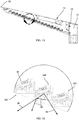
- FIG. 16 depicts the path of some light emitted from the housing 14 in accordance with various exemplary embodiments.
- Arrows 94 and 96 represent the bounded area of light that is emitted from the light source that can leave the housing due to the configuration of the brackets 34A-34C.
- Arrow 98 represents light that is directed from the optic 40. Instead of being emitted from the housing 14 parallel to the ground, the light represented by arrow 98 strikes the bracket 34C and is directed downward towards the ground.
- Arrows 94, 96, 98 represent only a portion of the light emitted from the light source as would be understood by one of ordinary skill in the art.
- FIGS. 17-20 show another exemplary embodiment of a first bracket 134A, a second bracket 134B, an LED board 136, a conductor grommet 138, one or more optics 140, a gasket 142, and a reflector 144.
- the first bracket 134A is configured to connect to a similar or identical second bracket 1348, for example through a mechanical connection such as a mating fit, an interference fit, or a snap fit.
- One or more mechanical fasteners 146 may be used to hold the first bracket 134A to the second bracket 134B and to secure one or more of the other elements in the lamp unit.
- the brackets 134A, 134B mate to form a stair-like pattern where each additional bracket is spaced outwardly and above the previous bracket.
- the bracket 134A includes a wall 148, a bottom member 150 extending from the wall 148 in a first direction and a top member 152 extending from the wall 148 in a second direction, giving the bracket 134A an approximately Z-shaped configuration.
- the bottom and top members 150, 152 are substantially rectangular plates.
- the bracket 134A is made from a rigid material, for example aluminum or other suitable metal, polymer, or composite material.
- the bracket 134A may be formed through machining, extrusions, molding, or other suitable processes.
- the wall 148 of the bracket 134A extends between the bottom member 150 and the top member 152.
- the wall 148 may be substantially vertical, orthogonal to the ground, or the wall 148 may have an angle of inclination relative to a vertical axis, for example between 0 and 10 degrees in either direction.
- the wall 148 has a front surface and a rear surface. The size, shape, and configuration of the wall 148 can be changed depending on the housing 12, the light source (not shown), and other design and utility considerations.
- the bottom member 150 extends obliquely from the bottom of the wall 148 in the first direction. In the exemplary embodiment shown, the bottom member 150 extends at an acute angle relative to the rear surface of the wall 148.
- the bottom member 150 has a first section with a first angle of inclination to the wall 148 and a second section with a second angle of inclination greater than the first angle of inclination relative to the wall 148.
- a first projection 154 extends from the bottom member 150 towards the top member 152 continuously along the width of the bottom member 150. In alternative embodiments, the height, shape, length, and position of the first projection 154 may vary according to the needs of the light source and the housing 14 and on the various types of required connections.
- a groove 156 is bound on one side by the first projection1 54 and on the other side by the wall 148.
- the groove 156 has a substantially rounded bottom.
- the bottom member 150 includes one or more light apertures 158 for receiving a light source and/or an optic 140 associated with a light source.
- the bottom member 150 also includes one or more fastener apertures 160 for receiving a mechanical fastener 146.
- the exemplary embodiment shown in FIGS. XXX depicts four light apertures 158 and four fastener apertures 160.
- the size, shape, and configuration of the bottom member 150 may vary according to the light source, the housing 14, and other design and utility considerations.
- the top member 152 extends obliquely from the top of the inches 48 in the second direction. In the exemplary embodiment shown, the top member 152 extends at an acute angle relative to the front surface of the wall. One or more heat fins 62 extend from the top member 152 to dissipate heat generated by the light source.
- the top member 152 includes a conductor aperture to receive the conductor grommet 138 and one or more fastener openings to receive a mechanical fastener 146.
- the conductor aperture allows conductors to pass through the top member 152 and connect to the LED board 136.
- the conductor grommet 138 protects the conductor passing through the bracket 134A from wear.
- a second projection 170 extends from the top member 152 in the direction of the bottom member 150. As best shown in FIGS. 18-20 , the second projection 170 is configured to mate with the groove 156 and/or the first projection 154 of the bottom member 150 to form a connection with an identical or similarly configured bracket 134B.
- the second projection includes a rounded portion 172 that extends below the top member 152 and an upper portion 174 that extends above the top member 152. When two brackets 134A, 134B are connected, a face or outer surface of the upper portion 174 is positioned in contact with or substantially adjacent to a surface of the wall 148.
- the top of the upper portion 174 has a first angled surface and a rear section of the top member 152 has a second angled surface.
- first and second angled surfaces are aligned and have a consistent slope.
- a second groove 164 can be formed in the upper portion 174.
- two or more brackets 134A-C are combined in a housing 114 to form separate lamp units.
- the LED board 136 and gasket 142 are placed on the top surface of the bottom member 150 of the first bracket 134A with the optics 140 extending through the light apertures 158.
- the reflector 144 is placed on the bottom surface of the bottom member 150 of the first bracket 134A.
- the second bracket 134B is positioned adjacent the first bracket 134A so that the top member 152 of the second bracket 134B is positioned over the bottom member 150 of the first bracket 134A.
- the first and second projections 154, 170 are mated so that the second projection 170 extends into the groove 156 adjacent the first projection 154.
- the first and second projections 154, 170 may be in contact with one another.
- the fasteners 146 are inserted through the top member 152 of the second bracket 134B, the gasket 142, the bottom member 150 of the first bracket 134A., and into the reflector 144.
- a backing member 115 can also be connected to the brackets 134A-C.
- One or more fasteners 116 are inserted through the backing member 115 and connected to the brackets 134A-C, for example by being inserted into the second slot 164.
- the second slot can include threads for engaging the fasteners 116, or self-taping fasteners can be used.
- the backing member 115 can provide rigidity and support the bracket assembly.
- the lamp units extend along the housing 114, at an angle and upwards away from the ground.
- the lamp units and the housing 114 prevent light from being emitted out of the housing 114 parallel to the ground and above the housing 114 relative to the ground.
- the light may be prevented from being emitted parallel to the ground in the front of the housing 114, from the sides of the housing 114, or a combination of both.
- the reflector 144, optic 140, and brackets 134A, 134B combine to prevent light from being emitted parallel to the ground in front of the housing 114 and from the side of the housing 114, while the lamp units are recessed in the housing 114 to prevent light from being emitted above the housing 114.
- the housing 114 may also assist in preventing light from being emitted parallel to the ground from the side of the housing 114.
- the terms “front,” “rear,” “upper,” “lower,” “upwardly,” “downwardly,”' and other orientational descriptors are intended to facilitate the description of the exemplary embodiments of the present invention, and are not intended to limit the structure of the exemplary embodiments of the present invention to any particular position or orientation.
- Terms of degree, such as “substantially” or “approximately” are understood by those of ordinary skill to refer to reasonable ranges outside of the given value, for example, general tolerances associated with manufacturing; assembly, and use of the described embodiments.
Landscapes
- Engineering & Computer Science (AREA)
- General Engineering & Computer Science (AREA)
- Non-Portable Lighting Devices Or Systems Thereof (AREA)
- Fastening Of Light Sources Or Lamp Holders (AREA)
- Arrangement Of Elements, Cooling, Sealing, Or The Like Of Lighting Devices (AREA)
Claims (13)
- Leuchte (10), umfassend:ein Gehäuse (14) mit einer Vertiefung;eine erste Halterung (34A, 134A), die in der Vertiefung des Gehäuses (14) positioniert ist, mit einem ersten Verbindungselement und einem zweiten Verbindungselement, wobei die erste Halterung (34A, 134A) eine Wand (48A, 148A), ein unteres Element (50A, 150A), das sich von der Wand (48A, 148A) in eine erste Richtung mit dem ersten Verbindungselement erstreckt, und ein oberes Element (52A, 152A), das sich von der Wand (48A, 148A) in eine zweite Richtung mit dem zweiten Verbindungselement erstreckt;eine zweite Halterung (34B, 134B), die in der Ausnehmung des Gehäuses (14) positioniert ist und ein drittes Verbindungselement und ein viertes Verbindungselement aufweist, wobei die zweite Halterung (34B, 134B) über das vierte und erste Verbindungselement mit der ersten Halterung (34A, 134A) verbunden ist, wobei die erste Halterung (34A, 134A) und die zweite Halterung (34B, 134B) treppenartig miteinander verbunden sind; und gekennzeichnet durcheinen Lichtsender, der mit mindestens einer der ersten Halterungen (34A, 134A) oder der zweiten Halterung (34B, 134B) derart verbunden ist, dass der Lichtsender zwischen dem oberen Element (52A, 152A) der ersten Halterung (34A, 134A) und einem unteren Element (50B, 150B) der zweiten Halterung (34B, 134B) positioniert ist.
- Leuchte nach Anspruch 1, wobei das erste Verbindungselement einen ersten Vorsprung (54A, 154A) im Wesentlichen parallel zur Wand (48A, 148A) und das zweite Verbindungselement einen zweiten Vorsprung (70A, 170A) im Wesentlichen parallel zur Wand (48A, 148A) beinhaltet.
- Leuchte nach Anspruch 1 oder 2, wobei das obere Element (152A) eine Nut (164A) aufweist und ein Stützelement (115) mit der ersten Halterung (134A) über ein Befestigungselement (116) verbunden ist, das sich in die Nut (164A) erstreckt.
- Leuchte nach einem vorhergehenden Anspruch, wobei das vom Lichtsender in einem ersten Winkel, der im Wesentlichen orthogonal zur Wand (48A, 148A) verläuft, ausgestrahlte Licht daran gehindert wird, das Gehäuse (14) in dem ersten Winkel zu verlassen.
- Leuchte nach Anspruch 4, wobei das in dem ersten Winkel ausgestrahlte Licht auf die zweite Halterung (34B, 134B) trifft.
- Leuchte nach einem vorhergehenden Anspruch, wobei der Lichtsender eine Linse (40) beinhaltet, die sich durch eine Öffnung (58, 158) in dem unteren Element (50A, 150A) erstreckt.
- Leuchte nach Anspruch 5, wobei eine Dichtung (42, 142) zwischen mindestens einem Abschnitt des Lichtsenders und dem unteren Element (50A, 150A) angeordnet ist.
- Leuchte nach einem vorhergehenden Anspruch, wobei das obere Element (52A, 12A) eine Leiteröffnung (68) aufweist und eine Leitungsdurchführung (38, 138) in der Leiteröffnung (68) positioniert ist.
- Leuchte nach einem vorhergehenden Anspruch, ferner umfassend einen Reflektor (44, 144), der auf der Unterseite des unteren Elements (50A, 150A) der ersten Halterung (34A, 134A) angeordnet ist.
- Leuchte nach Anspruch 9, wobei der Reflektor (44, 144) eine Basis (86), einen ersten Arm (88), der sich von der Basis (86) erstreckt, und einen zweiten Arm (90), der sich von der Basis (86) erstreckt, aufweist.
- Leuchte nach Anspruch 10, wobei die oberen und unteren Elemente im Wesentlichen rechteckige Platten sind und sich der erste und zweite Arm (88, 90) zu einem Punkt entlang ihrer Breite und Höhe verjüngen.
- Leuchte nach einem vorhergehenden Anspruch, wobei sich das untere Element (50A, 150A) schräg von der Wand (48A, 148) in eine erste Richtung erstreckt.
- Leuchte nach einem vorhergehenden Anspruch, wobei sich das obere Element (52A, 152A) schräg von der Wand (48A, 148) in eine zweite Richtung erstreckt.
Applications Claiming Priority (3)
| Application Number | Priority Date | Filing Date | Title |
|---|---|---|---|
| US201461992477P | 2014-05-13 | 2014-05-13 | |
| US14/689,423 US10215376B2 (en) | 2014-05-13 | 2015-04-17 | Light fixture having fixed angular position and lamp module for light fixtures |
| PCT/US2015/030316 WO2015175495A1 (en) | 2014-05-13 | 2015-05-12 | Light fixture having fixed angular position and lamp module for light fixtures |
Publications (3)
| Publication Number | Publication Date |
|---|---|
| EP3143324A1 EP3143324A1 (de) | 2017-03-22 |
| EP3143324A4 EP3143324A4 (de) | 2017-11-08 |
| EP3143324B1 true EP3143324B1 (de) | 2019-06-19 |
Family
ID=54480534
Family Applications (1)
| Application Number | Title | Priority Date | Filing Date |
|---|---|---|---|
| EP15792109.9A Active EP3143324B1 (de) | 2014-05-13 | 2015-05-12 | Leuchte mit fester winkelposition und lampenmodul für leuchten |
Country Status (6)
| Country | Link |
|---|---|
| US (2) | US10215376B2 (de) |
| EP (1) | EP3143324B1 (de) |
| AU (2) | AU2015259411B2 (de) |
| CA (1) | CA2948622C (de) |
| MX (2) | MX366387B (de) |
| WO (1) | WO2015175495A1 (de) |
Families Citing this family (7)
| Publication number | Priority date | Publication date | Assignee | Title |
|---|---|---|---|---|
| US10215376B2 (en) | 2014-05-13 | 2019-02-26 | Hubbell Incorporated | Light fixture having fixed angular position and lamp module for light fixtures |
| USD774243S1 (en) | 2015-04-10 | 2016-12-13 | Hubbell Incorporated | Lighting fixture |
| USD822254S1 (en) | 2015-04-17 | 2018-07-03 | Hubbell Incorporated | Light fixture |
| CA3011967A1 (en) | 2016-01-19 | 2017-07-27 | Hubbell Incorporated | Light fixture with shielded optic |
| WO2017127412A1 (en) | 2016-01-19 | 2017-07-27 | Hubbell Incorporated | Light fixture with pivotable optic |
| USD870947S1 (en) * | 2017-11-01 | 2019-12-24 | Hangzhou Amplesun Solar Technology Co., Ltd. | Solar lamp |
| BE1026261B1 (fr) * | 2018-05-08 | 2019-12-10 | Schreder Sa | Dispositif d’éclairage vers le bas et lampadaire comprenant un module d’éclairage sur mât doté de celui-ci |
Family Cites Families (35)
| Publication number | Priority date | Publication date | Assignee | Title |
|---|---|---|---|---|
| US2336016A (en) | 1941-11-12 | 1943-12-07 | Transit Advertisers Inc | Advertising device |
| US2496513A (en) | 1946-08-07 | 1950-02-07 | Ernest O Anders | Combination lighting and display fixture |
| US2800574A (en) | 1953-06-29 | 1957-07-23 | Compco Corp | Mounting for electric lighting fixtures |
| US2914657A (en) | 1957-05-02 | 1959-11-24 | Guardian Light Company | Outdoor lighting fixtures |
| US3264465A (en) | 1963-09-03 | 1966-08-02 | Gen Electric | Luminaire |
| JP3006812B2 (ja) | 1993-02-15 | 2000-02-07 | スタンレー電気株式会社 | 車両用信号灯具 |
| USD465593S1 (en) | 2001-11-05 | 2002-11-12 | Tsu-Kang Chang | Solar lamp |
| JP4005377B2 (ja) | 2002-01-31 | 2007-11-07 | 本田技研工業株式会社 | 車両用テールライト |
| USD493009S1 (en) | 2003-07-09 | 2004-07-13 | Luen Yick Electrical Mfg. Co., Ltd. | Shelf light |
| JP2005310584A (ja) | 2004-04-22 | 2005-11-04 | Koito Mfg Co Ltd | 車輌用灯具 |
| USD566876S1 (en) | 2005-04-15 | 2008-04-15 | Spi Lighting | Lighting fixture |
| US7828456B2 (en) | 2007-10-17 | 2010-11-09 | Lsi Industries, Inc. | Roadway luminaire and methods of use |
| US20090323343A1 (en) * | 2008-06-30 | 2009-12-31 | Pei-Choa Wang | Lamp base improvement of a street lamp |
| USD608040S1 (en) | 2008-11-21 | 2010-01-12 | Rab Lighting, Inc. | LED light fixture |
| US20130003379A1 (en) * | 2010-10-04 | 2013-01-03 | De Silva Niranjan B | Led light system |
| AU336532S (en) | 2010-12-22 | 2011-05-13 | Groupe Adeo S A | Solar lighting unit |
| CN202118667U (zh) | 2010-12-30 | 2012-01-18 | 北京朗波尔光电股份有限公司 | 一种应用于低位照明的led灯具 |
| DE102011017161A1 (de) * | 2011-04-15 | 2012-10-18 | Cooper Crouse-Hinds Gmbh | Leuchte |
| US8485684B2 (en) * | 2011-05-13 | 2013-07-16 | GE Lighting Solutions, LLC | LED roadway luminaire |
| WO2013032293A2 (ko) * | 2011-09-03 | 2013-03-07 | (주)엔티뱅크 | 엘이디 조명기구 |
| TW201314105A (zh) * | 2011-09-29 | 2013-04-01 | Foxsemicon Integrated Tech Inc | 發光二極體燈具 |
| KR101894040B1 (ko) * | 2011-12-06 | 2018-10-05 | 서울반도체 주식회사 | 엘이디 조명장치 |
| ES2864219T5 (es) | 2011-12-23 | 2024-11-14 | Signify Holding Bv | Luminaria de exteriores |
| USD672078S1 (en) | 2012-05-01 | 2012-12-04 | Foxsemicon Integrated Technology, Inc. | Illumination device |
| US9464790B2 (en) * | 2012-05-08 | 2016-10-11 | Cooper Technologies Company | Systems, methods, and devices for providing rotatable light modules and hinged mount in a luminaire |
| MX2013006164A (es) | 2012-06-01 | 2013-12-16 | Rab Lighting Inc | Arreglo de luminaria con configuracion seleccionable de emisor y reflector. |
| US9353917B2 (en) * | 2012-09-14 | 2016-05-31 | Cree, Inc. | High efficiency lighting device including one or more solid state light emitters, and method of lighting |
| KR101289752B1 (ko) * | 2012-12-14 | 2013-07-26 | 김종천 | 엘이디 램프 |
| USD729968S1 (en) | 2013-06-19 | 2015-05-19 | Hei Technology International Gmbh | Outdoor lighting fixture |
| USD707381S1 (en) | 2013-07-30 | 2014-06-17 | Lighting Science Group Corporation | Roadway lamp |
| US10215376B2 (en) | 2014-05-13 | 2019-02-26 | Hubbell Incorporated | Light fixture having fixed angular position and lamp module for light fixtures |
| USD732223S1 (en) | 2014-05-13 | 2015-06-16 | Hubbell Incorporated | Light fixture |
| USD757322S1 (en) | 2014-12-09 | 2016-05-24 | Hubbardton Forge Llc | Lamp |
| USD768904S1 (en) | 2015-04-10 | 2016-10-11 | Hubbell Incorporated | Lighting fixture |
| USD822254S1 (en) | 2015-04-17 | 2018-07-03 | Hubbell Incorporated | Light fixture |
-
2015
- 2015-04-17 US US14/689,423 patent/US10215376B2/en active Active
- 2015-05-12 EP EP15792109.9A patent/EP3143324B1/de active Active
- 2015-05-12 WO PCT/US2015/030316 patent/WO2015175495A1/en not_active Ceased
- 2015-05-12 AU AU2015259411A patent/AU2015259411B2/en active Active
- 2015-05-12 MX MX2016014889A patent/MX366387B/es active IP Right Grant
- 2015-05-12 CA CA2948622A patent/CA2948622C/en active Active
- 2015-05-12 MX MX2019007994A patent/MX395095B/es unknown
-
2019
- 2019-02-25 US US16/284,657 patent/US10920963B2/en active Active
-
2021
- 2021-02-26 AU AU2021201290A patent/AU2021201290B2/en active Active
Non-Patent Citations (1)
| Title |
|---|
| None * |
Also Published As
| Publication number | Publication date |
|---|---|
| US20190186715A1 (en) | 2019-06-20 |
| CA2948622A1 (en) | 2015-11-19 |
| AU2015259411B2 (en) | 2020-11-26 |
| US20150330609A1 (en) | 2015-11-19 |
| AU2015259411A1 (en) | 2016-11-24 |
| CA2948622C (en) | 2022-11-29 |
| US10215376B2 (en) | 2019-02-26 |
| MX2016014889A (es) | 2017-04-06 |
| MX366387B (es) | 2019-07-08 |
| AU2021201290A1 (en) | 2021-03-18 |
| WO2015175495A1 (en) | 2015-11-19 |
| AU2021201290A2 (en) | 2021-05-06 |
| MX2019007994A (es) | 2019-09-13 |
| EP3143324A4 (de) | 2017-11-08 |
| US10920963B2 (en) | 2021-02-16 |
| AU2021201290B2 (en) | 2022-09-15 |
| EP3143324A1 (de) | 2017-03-22 |
| MX395095B (es) | 2025-03-24 |
Similar Documents
| Publication | Publication Date | Title |
|---|---|---|
| AU2021201290B2 (en) | Light fixture having fixed angular position and lamp module for light fixtures | |
| JP6649408B2 (ja) | 傾斜した外壁を有するledベースの光源 | |
| US8696156B2 (en) | LED light bulb with light scattering optics structure | |
| US20150124449A1 (en) | Led light fixtures with arrangement for electrical connection | |
| US10151453B2 (en) | Directional accent luminaire | |
| US20140218933A1 (en) | Detachable lamp | |
| EP3208522B1 (de) | Omnidirektionale lichtemittierende led-lampe | |
| US10830429B2 (en) | Luminaire housing | |
| US20150062894A1 (en) | Hybrid Driving Light | |
| JP6114985B2 (ja) | 車両用前照灯 | |
| US11028999B2 (en) | Perimeter luminaire | |
| AU2016324345A1 (en) | Hybrid light assembly |
Legal Events
| Date | Code | Title | Description |
|---|---|---|---|
| STAA | Information on the status of an ep patent application or granted ep patent |
Free format text: STATUS: THE INTERNATIONAL PUBLICATION HAS BEEN MADE |
|
| PUAI | Public reference made under article 153(3) epc to a published international application that has entered the european phase |
Free format text: ORIGINAL CODE: 0009012 |
|
| STAA | Information on the status of an ep patent application or granted ep patent |
Free format text: STATUS: REQUEST FOR EXAMINATION WAS MADE |
|
| 17P | Request for examination filed |
Effective date: 20161115 |
|
| AK | Designated contracting states |
Kind code of ref document: A1 Designated state(s): AL AT BE BG CH CY CZ DE DK EE ES FI FR GB GR HR HU IE IS IT LI LT LU LV MC MK MT NL NO PL PT RO RS SE SI SK SM TR |
|
| AX | Request for extension of the european patent |
Extension state: BA ME |
|
| DAV | Request for validation of the european patent (deleted) | ||
| DAX | Request for extension of the european patent (deleted) | ||
| A4 | Supplementary search report drawn up and despatched |
Effective date: 20171006 |
|
| RIC1 | Information provided on ipc code assigned before grant |
Ipc: F21S 2/00 20160101ALI20170929BHEP Ipc: F21S 8/02 20060101AFI20170929BHEP Ipc: F21Y 103/10 20160101ALN20170929BHEP Ipc: F21Y 115/10 20160101ALN20170929BHEP Ipc: F21Y 107/60 20160101ALN20170929BHEP |
|
| RIC1 | Information provided on ipc code assigned before grant |
Ipc: F21S 2/00 20160101ALI20180712BHEP Ipc: F21Y 115/10 20160101ALN20180712BHEP Ipc: F21S 8/02 20060101AFI20180712BHEP Ipc: F21Y 107/60 20160101ALN20180712BHEP Ipc: F21Y 103/10 20160101ALN20180712BHEP |
|
| RIC1 | Information provided on ipc code assigned before grant |
Ipc: F21Y 103/10 20160101ALN20180928BHEP Ipc: F21Y 107/60 20160101ALN20180928BHEP Ipc: F21Y 115/10 20160101ALN20180928BHEP Ipc: F21S 2/00 20160101ALI20180928BHEP Ipc: F21S 8/02 20060101AFI20180928BHEP |
|
| GRAP | Despatch of communication of intention to grant a patent |
Free format text: ORIGINAL CODE: EPIDOSNIGR1 |
|
| STAA | Information on the status of an ep patent application or granted ep patent |
Free format text: STATUS: GRANT OF PATENT IS INTENDED |
|
| RIC1 | Information provided on ipc code assigned before grant |
Ipc: F21Y 115/10 20160101ALN20181029BHEP Ipc: F21Y 103/10 20160101ALN20181029BHEP Ipc: F21S 2/00 20160101ALI20181029BHEP Ipc: F21Y 107/60 20160101ALN20181029BHEP Ipc: F21S 8/02 20060101AFI20181029BHEP |
|
| INTG | Intention to grant announced |
Effective date: 20181130 |
|
| GRAS | Grant fee paid |
Free format text: ORIGINAL CODE: EPIDOSNIGR3 |
|
| GRAA | (expected) grant |
Free format text: ORIGINAL CODE: 0009210 |
|
| STAA | Information on the status of an ep patent application or granted ep patent |
Free format text: STATUS: THE PATENT HAS BEEN GRANTED |
|
| AK | Designated contracting states |
Kind code of ref document: B1 Designated state(s): AL AT BE BG CH CY CZ DE DK EE ES FI FR GB GR HR HU IE IS IT LI LT LU LV MC MK MT NL NO PL PT RO RS SE SI SK SM TR |
|
| REG | Reference to a national code |
Ref country code: GB Ref legal event code: FG4D |
|
| REG | Reference to a national code |
Ref country code: CH Ref legal event code: EP |
|
| REG | Reference to a national code |
Ref country code: IE Ref legal event code: FG4D |
|
| REG | Reference to a national code |
Ref country code: AT Ref legal event code: REF Ref document number: 1145990 Country of ref document: AT Kind code of ref document: T Effective date: 20190715 |
|
| REG | Reference to a national code |
Ref country code: DE Ref legal event code: R096 Ref document number: 602015032364 Country of ref document: DE |
|
| REG | Reference to a national code |
Ref country code: NL Ref legal event code: MP Effective date: 20190619 |
|
| PG25 | Lapsed in a contracting state [announced via postgrant information from national office to epo] |
Ref country code: LT Free format text: LAPSE BECAUSE OF FAILURE TO SUBMIT A TRANSLATION OF THE DESCRIPTION OR TO PAY THE FEE WITHIN THE PRESCRIBED TIME-LIMIT Effective date: 20190619 Ref country code: SE Free format text: LAPSE BECAUSE OF FAILURE TO SUBMIT A TRANSLATION OF THE DESCRIPTION OR TO PAY THE FEE WITHIN THE PRESCRIBED TIME-LIMIT Effective date: 20190619 Ref country code: HR Free format text: LAPSE BECAUSE OF FAILURE TO SUBMIT A TRANSLATION OF THE DESCRIPTION OR TO PAY THE FEE WITHIN THE PRESCRIBED TIME-LIMIT Effective date: 20190619 Ref country code: AL Free format text: LAPSE BECAUSE OF FAILURE TO SUBMIT A TRANSLATION OF THE DESCRIPTION OR TO PAY THE FEE WITHIN THE PRESCRIBED TIME-LIMIT Effective date: 20190619 Ref country code: NO Free format text: LAPSE BECAUSE OF FAILURE TO SUBMIT A TRANSLATION OF THE DESCRIPTION OR TO PAY THE FEE WITHIN THE PRESCRIBED TIME-LIMIT Effective date: 20190919 Ref country code: FI Free format text: LAPSE BECAUSE OF FAILURE TO SUBMIT A TRANSLATION OF THE DESCRIPTION OR TO PAY THE FEE WITHIN THE PRESCRIBED TIME-LIMIT Effective date: 20190619 |
|
| REG | Reference to a national code |
Ref country code: LT Ref legal event code: MG4D |
|
| PG25 | Lapsed in a contracting state [announced via postgrant information from national office to epo] |
Ref country code: LV Free format text: LAPSE BECAUSE OF FAILURE TO SUBMIT A TRANSLATION OF THE DESCRIPTION OR TO PAY THE FEE WITHIN THE PRESCRIBED TIME-LIMIT Effective date: 20190619 Ref country code: BG Free format text: LAPSE BECAUSE OF FAILURE TO SUBMIT A TRANSLATION OF THE DESCRIPTION OR TO PAY THE FEE WITHIN THE PRESCRIBED TIME-LIMIT Effective date: 20190919 Ref country code: RS Free format text: LAPSE BECAUSE OF FAILURE TO SUBMIT A TRANSLATION OF THE DESCRIPTION OR TO PAY THE FEE WITHIN THE PRESCRIBED TIME-LIMIT Effective date: 20190619 Ref country code: GR Free format text: LAPSE BECAUSE OF FAILURE TO SUBMIT A TRANSLATION OF THE DESCRIPTION OR TO PAY THE FEE WITHIN THE PRESCRIBED TIME-LIMIT Effective date: 20190920 |
|
| REG | Reference to a national code |
Ref country code: AT Ref legal event code: MK05 Ref document number: 1145990 Country of ref document: AT Kind code of ref document: T Effective date: 20190619 |
|
| PG25 | Lapsed in a contracting state [announced via postgrant information from national office to epo] |
Ref country code: CZ Free format text: LAPSE BECAUSE OF FAILURE TO SUBMIT A TRANSLATION OF THE DESCRIPTION OR TO PAY THE FEE WITHIN THE PRESCRIBED TIME-LIMIT Effective date: 20190619 Ref country code: RO Free format text: LAPSE BECAUSE OF FAILURE TO SUBMIT A TRANSLATION OF THE DESCRIPTION OR TO PAY THE FEE WITHIN THE PRESCRIBED TIME-LIMIT Effective date: 20190619 Ref country code: SK Free format text: LAPSE BECAUSE OF FAILURE TO SUBMIT A TRANSLATION OF THE DESCRIPTION OR TO PAY THE FEE WITHIN THE PRESCRIBED TIME-LIMIT Effective date: 20190619 Ref country code: NL Free format text: LAPSE BECAUSE OF FAILURE TO SUBMIT A TRANSLATION OF THE DESCRIPTION OR TO PAY THE FEE WITHIN THE PRESCRIBED TIME-LIMIT Effective date: 20190619 Ref country code: AT Free format text: LAPSE BECAUSE OF FAILURE TO SUBMIT A TRANSLATION OF THE DESCRIPTION OR TO PAY THE FEE WITHIN THE PRESCRIBED TIME-LIMIT Effective date: 20190619 Ref country code: EE Free format text: LAPSE BECAUSE OF FAILURE TO SUBMIT A TRANSLATION OF THE DESCRIPTION OR TO PAY THE FEE WITHIN THE PRESCRIBED TIME-LIMIT Effective date: 20190619 Ref country code: PT Free format text: LAPSE BECAUSE OF FAILURE TO SUBMIT A TRANSLATION OF THE DESCRIPTION OR TO PAY THE FEE WITHIN THE PRESCRIBED TIME-LIMIT Effective date: 20191021 |
|
| PG25 | Lapsed in a contracting state [announced via postgrant information from national office to epo] |
Ref country code: IT Free format text: LAPSE BECAUSE OF FAILURE TO SUBMIT A TRANSLATION OF THE DESCRIPTION OR TO PAY THE FEE WITHIN THE PRESCRIBED TIME-LIMIT Effective date: 20190619 Ref country code: ES Free format text: LAPSE BECAUSE OF FAILURE TO SUBMIT A TRANSLATION OF THE DESCRIPTION OR TO PAY THE FEE WITHIN THE PRESCRIBED TIME-LIMIT Effective date: 20190619 Ref country code: IS Free format text: LAPSE BECAUSE OF FAILURE TO SUBMIT A TRANSLATION OF THE DESCRIPTION OR TO PAY THE FEE WITHIN THE PRESCRIBED TIME-LIMIT Effective date: 20191019 Ref country code: SM Free format text: LAPSE BECAUSE OF FAILURE TO SUBMIT A TRANSLATION OF THE DESCRIPTION OR TO PAY THE FEE WITHIN THE PRESCRIBED TIME-LIMIT Effective date: 20190619 |
|
| PG25 | Lapsed in a contracting state [announced via postgrant information from national office to epo] |
Ref country code: TR Free format text: LAPSE BECAUSE OF FAILURE TO SUBMIT A TRANSLATION OF THE DESCRIPTION OR TO PAY THE FEE WITHIN THE PRESCRIBED TIME-LIMIT Effective date: 20190619 |
|
| PG25 | Lapsed in a contracting state [announced via postgrant information from national office to epo] |
Ref country code: DK Free format text: LAPSE BECAUSE OF FAILURE TO SUBMIT A TRANSLATION OF THE DESCRIPTION OR TO PAY THE FEE WITHIN THE PRESCRIBED TIME-LIMIT Effective date: 20190619 Ref country code: PL Free format text: LAPSE BECAUSE OF FAILURE TO SUBMIT A TRANSLATION OF THE DESCRIPTION OR TO PAY THE FEE WITHIN THE PRESCRIBED TIME-LIMIT Effective date: 20190619 |
|
| PG25 | Lapsed in a contracting state [announced via postgrant information from national office to epo] |
Ref country code: IS Free format text: LAPSE BECAUSE OF FAILURE TO SUBMIT A TRANSLATION OF THE DESCRIPTION OR TO PAY THE FEE WITHIN THE PRESCRIBED TIME-LIMIT Effective date: 20200224 |
|
| REG | Reference to a national code |
Ref country code: DE Ref legal event code: R097 Ref document number: 602015032364 Country of ref document: DE |
|
| PLBE | No opposition filed within time limit |
Free format text: ORIGINAL CODE: 0009261 |
|
| STAA | Information on the status of an ep patent application or granted ep patent |
Free format text: STATUS: NO OPPOSITION FILED WITHIN TIME LIMIT |
|
| PG2D | Information on lapse in contracting state deleted |
Ref country code: IS |
|
| 26N | No opposition filed |
Effective date: 20200603 |
|
| PG25 | Lapsed in a contracting state [announced via postgrant information from national office to epo] |
Ref country code: SI Free format text: LAPSE BECAUSE OF FAILURE TO SUBMIT A TRANSLATION OF THE DESCRIPTION OR TO PAY THE FEE WITHIN THE PRESCRIBED TIME-LIMIT Effective date: 20190619 |
|
| REG | Reference to a national code |
Ref country code: DE Ref legal event code: R119 Ref document number: 602015032364 Country of ref document: DE |
|
| PG25 | Lapsed in a contracting state [announced via postgrant information from national office to epo] |
Ref country code: MC Free format text: LAPSE BECAUSE OF FAILURE TO SUBMIT A TRANSLATION OF THE DESCRIPTION OR TO PAY THE FEE WITHIN THE PRESCRIBED TIME-LIMIT Effective date: 20190619 Ref country code: LI Free format text: LAPSE BECAUSE OF NON-PAYMENT OF DUE FEES Effective date: 20200531 Ref country code: CH Free format text: LAPSE BECAUSE OF NON-PAYMENT OF DUE FEES Effective date: 20200531 |
|
| REG | Reference to a national code |
Ref country code: BE Ref legal event code: MM Effective date: 20200531 |
|
| PG25 | Lapsed in a contracting state [announced via postgrant information from national office to epo] |
Ref country code: LU Free format text: LAPSE BECAUSE OF NON-PAYMENT OF DUE FEES Effective date: 20200512 |
|
| PG25 | Lapsed in a contracting state [announced via postgrant information from national office to epo] |
Ref country code: IE Free format text: LAPSE BECAUSE OF NON-PAYMENT OF DUE FEES Effective date: 20200512 |
|
| PG25 | Lapsed in a contracting state [announced via postgrant information from national office to epo] |
Ref country code: DE Free format text: LAPSE BECAUSE OF NON-PAYMENT OF DUE FEES Effective date: 20201201 Ref country code: BE Free format text: LAPSE BECAUSE OF NON-PAYMENT OF DUE FEES Effective date: 20200531 |
|
| REG | Reference to a national code |
Ref country code: GB Ref legal event code: 732E Free format text: REGISTERED BETWEEN 20220310 AND 20220316 |
|
| PG25 | Lapsed in a contracting state [announced via postgrant information from national office to epo] |
Ref country code: MT Free format text: LAPSE BECAUSE OF FAILURE TO SUBMIT A TRANSLATION OF THE DESCRIPTION OR TO PAY THE FEE WITHIN THE PRESCRIBED TIME-LIMIT Effective date: 20190619 Ref country code: CY Free format text: LAPSE BECAUSE OF FAILURE TO SUBMIT A TRANSLATION OF THE DESCRIPTION OR TO PAY THE FEE WITHIN THE PRESCRIBED TIME-LIMIT Effective date: 20190619 |
|
| PG25 | Lapsed in a contracting state [announced via postgrant information from national office to epo] |
Ref country code: MK Free format text: LAPSE BECAUSE OF FAILURE TO SUBMIT A TRANSLATION OF THE DESCRIPTION OR TO PAY THE FEE WITHIN THE PRESCRIBED TIME-LIMIT Effective date: 20190619 |
|
| PGFP | Annual fee paid to national office [announced via postgrant information from national office to epo] |
Ref country code: FR Payment date: 20220525 Year of fee payment: 8 |
|
| PGFP | Annual fee paid to national office [announced via postgrant information from national office to epo] |
Ref country code: GB Payment date: 20230420 Year of fee payment: 9 |
|
| PG25 | Lapsed in a contracting state [announced via postgrant information from national office to epo] |
Ref country code: FR Free format text: LAPSE BECAUSE OF NON-PAYMENT OF DUE FEES Effective date: 20230531 |
|
| GBPC | Gb: european patent ceased through non-payment of renewal fee |
Effective date: 20240512 |
|
| PG25 | Lapsed in a contracting state [announced via postgrant information from national office to epo] |
Ref country code: GB Free format text: LAPSE BECAUSE OF NON-PAYMENT OF DUE FEES Effective date: 20240512 |