EP3143255B1 - Nettoyage et séparation de fluide et de débris d'échantillons de carottage et systèmes de carottage - Google Patents
Nettoyage et séparation de fluide et de débris d'échantillons de carottage et systèmes de carottage Download PDFInfo
- Publication number
- EP3143255B1 EP3143255B1 EP15829400.9A EP15829400A EP3143255B1 EP 3143255 B1 EP3143255 B1 EP 3143255B1 EP 15829400 A EP15829400 A EP 15829400A EP 3143255 B1 EP3143255 B1 EP 3143255B1
- Authority
- EP
- European Patent Office
- Prior art keywords
- fluid
- heavy weight
- wellbore
- carrier chamber
- coring tool
- Prior art date
- Legal status (The legal status is an assumption and is not a legal conclusion. Google has not performed a legal analysis and makes no representation as to the accuracy of the status listed.)
- Active
Links
- 239000012530 fluid Substances 0.000 title claims description 86
- 238000004140 cleaning Methods 0.000 title description 4
- 230000015572 biosynthetic process Effects 0.000 claims description 20
- 238000000034 method Methods 0.000 claims description 16
- 150000003839 salts Chemical class 0.000 claims description 16
- 239000004215 Carbon black (E152) Substances 0.000 claims description 8
- 229930195733 hydrocarbon Natural products 0.000 claims description 8
- 150000002430 hydrocarbons Chemical class 0.000 claims description 8
- 230000004913 activation Effects 0.000 claims description 7
- 230000007246 mechanism Effects 0.000 claims description 7
- IOLCXVTUBQKXJR-UHFFFAOYSA-M potassium bromide Chemical compound [K+].[Br-] IOLCXVTUBQKXJR-UHFFFAOYSA-M 0.000 claims description 6
- JHJLBTNAGRQEKS-UHFFFAOYSA-M sodium bromide Chemical compound [Na+].[Br-] JHJLBTNAGRQEKS-UHFFFAOYSA-M 0.000 claims description 6
- ATZQZZAXOPPAAQ-UHFFFAOYSA-M caesium formate Chemical compound [Cs+].[O-]C=O ATZQZZAXOPPAAQ-UHFFFAOYSA-M 0.000 claims description 4
- 229910001622 calcium bromide Inorganic materials 0.000 claims description 4
- WGEFECGEFUFIQW-UHFFFAOYSA-L calcium dibromide Chemical compound [Ca+2].[Br-].[Br-] WGEFECGEFUFIQW-UHFFFAOYSA-L 0.000 claims description 4
- 239000003002 pH adjusting agent Substances 0.000 claims description 4
- LCIQMVZXQUMARP-UHFFFAOYSA-M cesium;bromate Chemical compound [Cs+].[O-]Br(=O)=O LCIQMVZXQUMARP-UHFFFAOYSA-M 0.000 claims description 3
- WFIZEGIEIOHZCP-UHFFFAOYSA-M potassium formate Chemical compound [K+].[O-]C=O WFIZEGIEIOHZCP-UHFFFAOYSA-M 0.000 claims description 3
- 238000011010 flushing procedure Methods 0.000 claims description 2
- 230000001747 exhibiting effect Effects 0.000 claims 1
- 238000005553 drilling Methods 0.000 description 23
- 238000005755 formation reaction Methods 0.000 description 18
- 239000011435 rock Substances 0.000 description 9
- 239000004088 foaming agent Substances 0.000 description 8
- 239000007789 gas Substances 0.000 description 8
- 244000007835 Cyamopsis tetragonoloba Species 0.000 description 6
- 239000012267 brine Substances 0.000 description 5
- 239000000203 mixture Substances 0.000 description 5
- -1 pyranosyl sulfate Chemical compound 0.000 description 5
- HPALAKNZSZLMCH-UHFFFAOYSA-M sodium;chloride;hydrate Chemical compound O.[Na+].[Cl-] HPALAKNZSZLMCH-UHFFFAOYSA-M 0.000 description 5
- XLYOFNOQVPJJNP-UHFFFAOYSA-N water Substances O XLYOFNOQVPJJNP-UHFFFAOYSA-N 0.000 description 5
- IJGRMHOSHXDMSA-UHFFFAOYSA-N Atomic nitrogen Chemical compound N#N IJGRMHOSHXDMSA-UHFFFAOYSA-N 0.000 description 4
- CURLTUGMZLYLDI-UHFFFAOYSA-N Carbon dioxide Chemical compound O=C=O CURLTUGMZLYLDI-UHFFFAOYSA-N 0.000 description 4
- 239000003349 gelling agent Substances 0.000 description 4
- 239000000463 material Substances 0.000 description 4
- 238000012360 testing method Methods 0.000 description 4
- HEMHJVSKTPXQMS-UHFFFAOYSA-M Sodium hydroxide Chemical compound [OH-].[Na+] HEMHJVSKTPXQMS-UHFFFAOYSA-M 0.000 description 3
- 239000000654 additive Substances 0.000 description 3
- 230000008901 benefit Effects 0.000 description 3
- 230000000694 effects Effects 0.000 description 3
- 238000012986 modification Methods 0.000 description 3
- 230000004048 modification Effects 0.000 description 3
- 238000000926 separation method Methods 0.000 description 3
- JKNCOURZONDCGV-UHFFFAOYSA-N 2-(dimethylamino)ethyl 2-methylprop-2-enoate Chemical compound CN(C)CCOC(=O)C(C)=C JKNCOURZONDCGV-UHFFFAOYSA-N 0.000 description 2
- XKRFYHLGVUSROY-UHFFFAOYSA-N Argon Chemical compound [Ar] XKRFYHLGVUSROY-UHFFFAOYSA-N 0.000 description 2
- SRBFZHDQGSBBOR-IOVATXLUSA-N D-xylopyranose Chemical compound O[C@@H]1COC(O)[C@H](O)[C@H]1O SRBFZHDQGSBBOR-IOVATXLUSA-N 0.000 description 2
- VEXZGXHMUGYJMC-UHFFFAOYSA-N Hydrochloric acid Chemical compound Cl VEXZGXHMUGYJMC-UHFFFAOYSA-N 0.000 description 2
- CDBYLPFSWZWCQE-UHFFFAOYSA-L Sodium Carbonate Chemical compound [Na+].[Na+].[O-]C([O-])=O CDBYLPFSWZWCQE-UHFFFAOYSA-L 0.000 description 2
- QAOWNCQODCNURD-UHFFFAOYSA-N Sulfuric acid Chemical compound OS(O)(=O)=O QAOWNCQODCNURD-UHFFFAOYSA-N 0.000 description 2
- PYMYPHUHKUWMLA-UHFFFAOYSA-N arabinose Natural products OCC(O)C(O)C(O)C=O PYMYPHUHKUWMLA-UHFFFAOYSA-N 0.000 description 2
- SRBFZHDQGSBBOR-UHFFFAOYSA-N beta-D-Pyranose-Lyxose Natural products OC1COC(O)C(O)C1O SRBFZHDQGSBBOR-UHFFFAOYSA-N 0.000 description 2
- 239000001569 carbon dioxide Substances 0.000 description 2
- 229910002092 carbon dioxide Inorganic materials 0.000 description 2
- 238000005260 corrosion Methods 0.000 description 2
- 230000007797 corrosion Effects 0.000 description 2
- 238000013461 design Methods 0.000 description 2
- 239000003112 inhibitor Substances 0.000 description 2
- 229910052500 inorganic mineral Inorganic materials 0.000 description 2
- 238000004519 manufacturing process Methods 0.000 description 2
- BDAGIHXWWSANSR-UHFFFAOYSA-N methanoic acid Natural products OC=O BDAGIHXWWSANSR-UHFFFAOYSA-N 0.000 description 2
- 239000011707 mineral Substances 0.000 description 2
- 235000010755 mineral Nutrition 0.000 description 2
- 229910052757 nitrogen Inorganic materials 0.000 description 2
- 230000009257 reactivity Effects 0.000 description 2
- 238000005070 sampling Methods 0.000 description 2
- 238000003860 storage Methods 0.000 description 2
- 239000000126 substance Substances 0.000 description 2
- 239000004094 surface-active agent Substances 0.000 description 2
- DPBJAVGHACCNRL-UHFFFAOYSA-N 2-(dimethylamino)ethyl prop-2-enoate Chemical compound CN(C)CCOC(=O)C=C DPBJAVGHACCNRL-UHFFFAOYSA-N 0.000 description 1
- FEBUJFMRSBAMES-UHFFFAOYSA-N 2-[(2-{[3,5-dihydroxy-2-(hydroxymethyl)-6-phosphanyloxan-4-yl]oxy}-3,5-dihydroxy-6-({[3,4,5-trihydroxy-6-(hydroxymethyl)oxan-2-yl]oxy}methyl)oxan-4-yl)oxy]-3,5-dihydroxy-6-(hydroxymethyl)oxan-4-yl phosphinite Chemical compound OC1C(O)C(O)C(CO)OC1OCC1C(O)C(OC2C(C(OP)C(O)C(CO)O2)O)C(O)C(OC2C(C(CO)OC(P)C2O)O)O1 FEBUJFMRSBAMES-UHFFFAOYSA-N 0.000 description 1
- OSWFIVFLDKOXQC-UHFFFAOYSA-N 4-(3-methoxyphenyl)aniline Chemical compound COC1=CC=CC(C=2C=CC(N)=CC=2)=C1 OSWFIVFLDKOXQC-UHFFFAOYSA-N 0.000 description 1
- FLCAEMBIQVZWIF-UHFFFAOYSA-N 6-(dimethylamino)-2-methylhex-2-enamide Chemical compound CN(C)CCCC=C(C)C(N)=O FLCAEMBIQVZWIF-UHFFFAOYSA-N 0.000 description 1
- GJCOSYZMQJWQCA-UHFFFAOYSA-N 9H-xanthene Chemical compound C1=CC=C2CC3=CC=CC=C3OC2=C1 GJCOSYZMQJWQCA-UHFFFAOYSA-N 0.000 description 1
- HRPVXLWXLXDGHG-UHFFFAOYSA-N Acrylamide Chemical compound NC(=O)C=C HRPVXLWXLXDGHG-UHFFFAOYSA-N 0.000 description 1
- NIXOWILDQLNWCW-UHFFFAOYSA-M Acrylate Chemical compound [O-]C(=O)C=C NIXOWILDQLNWCW-UHFFFAOYSA-M 0.000 description 1
- GAWIXWVDTYZWAW-UHFFFAOYSA-N C[CH]O Chemical group C[CH]O GAWIXWVDTYZWAW-UHFFFAOYSA-N 0.000 description 1
- 229920002134 Carboxymethyl cellulose Polymers 0.000 description 1
- LZZYPRNAOMGNLH-UHFFFAOYSA-M Cetrimonium bromide Chemical compound [Br-].CCCCCCCCCCCCCCCC[N+](C)(C)C LZZYPRNAOMGNLH-UHFFFAOYSA-M 0.000 description 1
- WQZGKKKJIJFFOK-QTVWNMPRSA-N D-mannopyranose Chemical compound OC[C@H]1OC(O)[C@@H](O)[C@@H](O)[C@@H]1O WQZGKKKJIJFFOK-QTVWNMPRSA-N 0.000 description 1
- 229930091371 Fructose Natural products 0.000 description 1
- RFSUNEUAIZKAJO-ARQDHWQXSA-N Fructose Chemical compound OC[C@H]1O[C@](O)(CO)[C@@H](O)[C@@H]1O RFSUNEUAIZKAJO-ARQDHWQXSA-N 0.000 description 1
- 239000005715 Fructose Substances 0.000 description 1
- IAJILQKETJEXLJ-UHFFFAOYSA-N Galacturonsaeure Natural products O=CC(O)C(O)C(O)C(O)C(O)=O IAJILQKETJEXLJ-UHFFFAOYSA-N 0.000 description 1
- WQZGKKKJIJFFOK-GASJEMHNSA-N Glucose Natural products OC[C@H]1OC(O)[C@H](O)[C@@H](O)[C@@H]1O WQZGKKKJIJFFOK-GASJEMHNSA-N 0.000 description 1
- 229920000663 Hydroxyethyl cellulose Polymers 0.000 description 1
- 239000004354 Hydroxyethyl cellulose Substances 0.000 description 1
- 229920002305 Schizophyllan Polymers 0.000 description 1
- UIIMBOGNXHQVGW-DEQYMQKBSA-M Sodium bicarbonate-14C Chemical compound [Na+].O[14C]([O-])=O UIIMBOGNXHQVGW-DEQYMQKBSA-M 0.000 description 1
- DBMJMQXJHONAFJ-UHFFFAOYSA-M Sodium laurylsulphate Chemical compound [Na+].CCCCCCCCCCCCOS([O-])(=O)=O DBMJMQXJHONAFJ-UHFFFAOYSA-M 0.000 description 1
- 230000002378 acidificating effect Effects 0.000 description 1
- 230000000996 additive effect Effects 0.000 description 1
- 230000002411 adverse Effects 0.000 description 1
- 239000003570 air Substances 0.000 description 1
- 150000001298 alcohols Chemical class 0.000 description 1
- IAJILQKETJEXLJ-QTBDOELSSA-N aldehydo-D-glucuronic acid Chemical compound O=C[C@H](O)[C@@H](O)[C@H](O)[C@H](O)C(O)=O IAJILQKETJEXLJ-QTBDOELSSA-N 0.000 description 1
- 150000008055 alkyl aryl sulfonates Chemical class 0.000 description 1
- 125000000217 alkyl group Chemical group 0.000 description 1
- 229940045714 alkyl sulfonate alkylating agent Drugs 0.000 description 1
- 150000008052 alkyl sulfonates Chemical class 0.000 description 1
- WQZGKKKJIJFFOK-PHYPRBDBSA-N alpha-D-galactose Chemical compound OC[C@H]1O[C@H](O)[C@H](O)[C@@H](O)[C@H]1O WQZGKKKJIJFFOK-PHYPRBDBSA-N 0.000 description 1
- 230000004075 alteration Effects 0.000 description 1
- 150000001412 amines Chemical group 0.000 description 1
- 125000000129 anionic group Chemical group 0.000 description 1
- PYMYPHUHKUWMLA-WDCZJNDASA-N arabinose Chemical compound OC[C@@H](O)[C@@H](O)[C@H](O)C=O PYMYPHUHKUWMLA-WDCZJNDASA-N 0.000 description 1
- 229910052786 argon Inorganic materials 0.000 description 1
- WQZGKKKJIJFFOK-VFUOTHLCSA-N beta-D-glucose Chemical compound OC[C@H]1O[C@@H](O)[C@H](O)[C@@H](O)[C@@H]1O WQZGKKKJIJFFOK-VFUOTHLCSA-N 0.000 description 1
- 230000003115 biocidal effect Effects 0.000 description 1
- 239000003139 biocide Substances 0.000 description 1
- 229920001222 biopolymer Polymers 0.000 description 1
- 239000001768 carboxy methyl cellulose Substances 0.000 description 1
- 235000010948 carboxy methyl cellulose Nutrition 0.000 description 1
- 229920003064 carboxyethyl cellulose Polymers 0.000 description 1
- 125000002057 carboxymethyl group Chemical group [H]OC(=O)C([H])([H])[*] 0.000 description 1
- 229920003090 carboxymethyl hydroxyethyl cellulose Polymers 0.000 description 1
- 239000008112 carboxymethyl-cellulose Substances 0.000 description 1
- 125000002091 cationic group Chemical group 0.000 description 1
- 239000001913 cellulose Substances 0.000 description 1
- 229920002678 cellulose Polymers 0.000 description 1
- 238000006243 chemical reaction Methods 0.000 description 1
- 239000007795 chemical reaction product Substances 0.000 description 1
- 239000003638 chemical reducing agent Substances 0.000 description 1
- 239000003795 chemical substances by application Substances 0.000 description 1
- 239000004927 clay Substances 0.000 description 1
- 150000001875 compounds Chemical class 0.000 description 1
- 238000010276 construction Methods 0.000 description 1
- 239000008367 deionised water Substances 0.000 description 1
- 229910021641 deionized water Inorganic materials 0.000 description 1
- 238000011161 development Methods 0.000 description 1
- 239000006185 dispersion Substances 0.000 description 1
- 238000006073 displacement reaction Methods 0.000 description 1
- 239000003995 emulsifying agent Substances 0.000 description 1
- RTZKZFJDLAIYFH-UHFFFAOYSA-N ether Substances CCOCC RTZKZFJDLAIYFH-UHFFFAOYSA-N 0.000 description 1
- 150000002170 ethers Chemical class 0.000 description 1
- 238000011156 evaluation Methods 0.000 description 1
- 235000019253 formic acid Nutrition 0.000 description 1
- 239000012634 fragment Substances 0.000 description 1
- 239000013505 freshwater Substances 0.000 description 1
- 229930182830 galactose Natural products 0.000 description 1
- 239000008103 glucose Substances 0.000 description 1
- 229930182478 glucoside Natural products 0.000 description 1
- 150000008131 glucosides Chemical class 0.000 description 1
- 229940097043 glucuronic acid Drugs 0.000 description 1
- 150000004676 glycans Chemical class 0.000 description 1
- 230000036541 health Effects 0.000 description 1
- 239000001307 helium Substances 0.000 description 1
- 229910052734 helium Inorganic materials 0.000 description 1
- SWQJXJOGLNCZEY-UHFFFAOYSA-N helium atom Chemical compound [He] SWQJXJOGLNCZEY-UHFFFAOYSA-N 0.000 description 1
- 235000019447 hydroxyethyl cellulose Nutrition 0.000 description 1
- 238000011065 in-situ storage Methods 0.000 description 1
- 239000004615 ingredient Substances 0.000 description 1
- 238000002347 injection Methods 0.000 description 1
- 239000007924 injection Substances 0.000 description 1
- 239000000395 magnesium oxide Substances 0.000 description 1
- CPLXHLVBOLITMK-UHFFFAOYSA-N magnesium oxide Inorganic materials [Mg]=O CPLXHLVBOLITMK-UHFFFAOYSA-N 0.000 description 1
- AXZKOIWUVFPNLO-UHFFFAOYSA-N magnesium;oxygen(2-) Chemical compound [O-2].[Mg+2] AXZKOIWUVFPNLO-UHFFFAOYSA-N 0.000 description 1
- 238000005259 measurement Methods 0.000 description 1
- NMJORVOYSJLJGU-UHFFFAOYSA-N methane clathrate Chemical compound C.C.C.C.O.O.O.O.O.O.O.O.O.O.O.O.O.O.O.O.O.O.O.O.O.O.O NMJORVOYSJLJGU-UHFFFAOYSA-N 0.000 description 1
- 150000002772 monosaccharides Chemical group 0.000 description 1
- DCBBWYIVFRLKCD-UHFFFAOYSA-N n-[2-(dimethylamino)ethyl]-2-methylprop-2-enamide Chemical compound CN(C)CCNC(=O)C(C)=C DCBBWYIVFRLKCD-UHFFFAOYSA-N 0.000 description 1
- 229920006280 packaging film Polymers 0.000 description 1
- 239000012785 packaging film Substances 0.000 description 1
- 230000035699 permeability Effects 0.000 description 1
- 150000002989 phenols Chemical class 0.000 description 1
- 229920002401 polyacrylamide Polymers 0.000 description 1
- 229920001223 polyethylene glycol Polymers 0.000 description 1
- 229920000642 polymer Polymers 0.000 description 1
- 229920001282 polysaccharide Polymers 0.000 description 1
- 239000005017 polysaccharide Substances 0.000 description 1
- 239000011148 porous material Substances 0.000 description 1
- 239000002455 scale inhibitor Substances 0.000 description 1
- 229910000029 sodium carbonate Inorganic materials 0.000 description 1
- 229940083575 sodium dodecyl sulfate Drugs 0.000 description 1
- 235000019333 sodium laurylsulphate Nutrition 0.000 description 1
- DAJSVUQLFFJUSX-UHFFFAOYSA-M sodium;dodecane-1-sulfonate Chemical compound [Na+].CCCCCCCCCCCCS([O-])(=O)=O DAJSVUQLFFJUSX-UHFFFAOYSA-M 0.000 description 1
- 239000007787 solid Substances 0.000 description 1
- 239000000243 solution Substances 0.000 description 1
- 239000003381 stabilizer Substances 0.000 description 1
- 230000000087 stabilizing effect Effects 0.000 description 1
- 150000003871 sulfonates Chemical class 0.000 description 1
- 229920001059 synthetic polymer Polymers 0.000 description 1
- ISXSCDLOGDJUNJ-UHFFFAOYSA-N tert-butyl prop-2-enoate Chemical compound CC(C)(C)OC(=O)C=C ISXSCDLOGDJUNJ-UHFFFAOYSA-N 0.000 description 1
- 231100000331 toxic Toxicity 0.000 description 1
- 230000002588 toxic effect Effects 0.000 description 1
- 238000013519 translation Methods 0.000 description 1
- 229920001285 xanthan gum Polymers 0.000 description 1
- 239000004711 α-olefin Substances 0.000 description 1
Images


Classifications
-
- E—FIXED CONSTRUCTIONS
- E21—EARTH OR ROCK DRILLING; MINING
- E21B—EARTH OR ROCK DRILLING; OBTAINING OIL, GAS, WATER, SOLUBLE OR MELTABLE MATERIALS OR A SLURRY OF MINERALS FROM WELLS
- E21B25/00—Apparatus for obtaining or removing undisturbed cores, e.g. core barrels or core extractors
- E21B25/10—Formed core retaining or severing means
-
- E—FIXED CONSTRUCTIONS
- E21—EARTH OR ROCK DRILLING; MINING
- E21B—EARTH OR ROCK DRILLING; OBTAINING OIL, GAS, WATER, SOLUBLE OR MELTABLE MATERIALS OR A SLURRY OF MINERALS FROM WELLS
- E21B49/00—Testing the nature of borehole walls; Formation testing; Methods or apparatus for obtaining samples of soil or well fluids, specially adapted to earth drilling or wells
- E21B49/02—Testing the nature of borehole walls; Formation testing; Methods or apparatus for obtaining samples of soil or well fluids, specially adapted to earth drilling or wells by mechanically taking samples of the soil
- E21B49/06—Testing the nature of borehole walls; Formation testing; Methods or apparatus for obtaining samples of soil or well fluids, specially adapted to earth drilling or wells by mechanically taking samples of the soil using side-wall drilling tools pressing or scrapers
-
- C—CHEMISTRY; METALLURGY
- C09—DYES; PAINTS; POLISHES; NATURAL RESINS; ADHESIVES; COMPOSITIONS NOT OTHERWISE PROVIDED FOR; APPLICATIONS OF MATERIALS NOT OTHERWISE PROVIDED FOR
- C09K—MATERIALS FOR MISCELLANEOUS APPLICATIONS, NOT PROVIDED FOR ELSEWHERE
- C09K8/00—Compositions for drilling of boreholes or wells; Compositions for treating boreholes or wells, e.g. for completion or for remedial operations
-
- E—FIXED CONSTRUCTIONS
- E21—EARTH OR ROCK DRILLING; MINING
- E21B—EARTH OR ROCK DRILLING; OBTAINING OIL, GAS, WATER, SOLUBLE OR MELTABLE MATERIALS OR A SLURRY OF MINERALS FROM WELLS
- E21B25/00—Apparatus for obtaining or removing undisturbed cores, e.g. core barrels or core extractors
- E21B25/02—Apparatus for obtaining or removing undisturbed cores, e.g. core barrels or core extractors the core receiver being insertable into, or removable from, the borehole without withdrawing the drilling pipe
-
- E—FIXED CONSTRUCTIONS
- E21—EARTH OR ROCK DRILLING; MINING
- E21B—EARTH OR ROCK DRILLING; OBTAINING OIL, GAS, WATER, SOLUBLE OR MELTABLE MATERIALS OR A SLURRY OF MINERALS FROM WELLS
- E21B25/00—Apparatus for obtaining or removing undisturbed cores, e.g. core barrels or core extractors
- E21B25/08—Coating, freezing, consolidating cores; Recovering uncontaminated cores or cores at formation pressure
-
- E—FIXED CONSTRUCTIONS
- E02—HYDRAULIC ENGINEERING; FOUNDATIONS; SOIL SHIFTING
- E02D—FOUNDATIONS; EXCAVATIONS; EMBANKMENTS; UNDERGROUND OR UNDERWATER STRUCTURES
- E02D2300/00—Materials
Definitions
- the present disclosure relates to the collection of core samples and, more particularly, to cleaning and separating fluid and debris from collected core samples and core systems.
- the core sample may be analyzed to asses, among other purposes, the reservoir storage capacity (porosity), the flow potential (permeability) of the rock material that makes up the formation, the chemical and mineral composition of the mineral deposits residing in the pores of the formation, and the irreducible water content of the rock material.
- the information gleaned from analysis of the sample is used to design and implement well completion; that is, to selectively produce certain economically attractive treatment intervals from among those accessible by the well.
- all intervals except those specifically targeted for production are isolated from the target interval, and the deposits within the targeted interval are selectively produced through the well.
- an annular cutter called a coring head is deployed on the end of a tool string.
- the coring head is operable to remove an annular volume of material to create a core, which may then be captured and placed in a collection tube and subsequently retrieved to surface for analysis.
- drilling fluid and debris within a wellbore e.g ., rock fragments from the wellbore wall
- This debris can contaminate the core sample, resulting in skewed testing results once received at the surface and analyzed. It also may cause the core collection chamber to become choked, which, among other things, may result in inability to obtain the requisite or maximum number of samples which may be recovered with a particular coring tool.
- the core sampling storage module includes a pressure housing to store a plurality of core samples, a core tube within the pressure housing, the core tube to store a plurality of core samples drilled from a downhole formation, a pressure housing cover that is configured to be selectively rotated to an open position or a closed position, an activation mechanism to receive a command, and based on the command, open or close the pressure housing cover, a push rod to selectively install a plug to cover the core tube, wherein when the plug is installed the pressure housing maintains a pressure.
- US 2001/0000393 A1 is further prior art. The invention is defined by the independent claims.
- the present disclosure relates to the collection of core samples and, more particularly, to cleaning and separating fluid and debris from collected core samples and core systems.
- Embodiments described herein discuss providing a clean environment for core sample collection, as well as providing a reliable way to seal and maintain downhole pressures in a core collection tube of a coring tool.
- Embodiments of the present disclosure may be applicable to horizontal, vertical, deviated, or otherwise nonlinear wellbores in any type of subterranean formation.
- Embodiments may be applicable to injection wells as well as production wells, including hydrocarbon wells.
- Embodiments may be implemented in which the coring tool is made suitable for testing, retrieval and sampling along sections of the formation.
- Embodiments may be implemented with various samplers that, for example, may be conveyed through flow passage in tubular string or conveyance, such as using a wireline, slickline, coiled tubing, downhole robot (tractor), or the like.
- the system described herein may be suited for use with the Hostile Rotary Sidewall Coring Tool (HRSCT-B) available from Halliburton Energy Services of Houston, Texas, for example.
- HRSCT-B Hostile Rotary Sidewall Coring Tool
- the method described herein may be used in one or more of wireline, measurement-while-drilling (MWD) and logging-while-drilling (LWD) operations.
- MWD measurement-while-drilling
- LWD logging-while-drilling
- compositions and methods are described herein in terms of “comprising” various components or steps, the compositions and methods can also “consist essentially of” or “consist of” the various components and steps. When “comprising” is used in a claim, it is open-ended.
- the term “substantially” means largely, but not necessarily wholly.
- FIG. 1 shows an example system 100 that may employ the principles of the present disclosure.
- a coring tool 110 is placed in a wellbore by a wireline 115.
- the coring tool 110 is placed in the wellbore by any conveyance, such as those discussed above (e.g., wired coil tubing) that is connectable to the surface.
- the coring tool 110 may be placed in the wellbore as part of a measurement while drilling (MWD) portion of a drill string or as part of a logging while drilling (LWD) portion of a drill string.
- the coring tool 110 may be coupled to drill pipe as part of a wired drill pipe system.
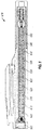
- FIG. 2 shows a side view of a coring tool 16, which may be substantially similar to the coring tool 110 of FIG. 1 , lowered to a depth of interest within the wellbore.
- the coring tool 16 includes a sidewall drilling tool 205 and a high pressure core module 210. Once the coring tool 110 reaches a region of interest, the sidewall drilling tool 205 may be configured to extend a stabilizing pad 215 to engage the wall of the wellbore and then rotate to face the wellbore wall for obtaining a sidewall core therefrom.
- FIGS. 3A-3C show an enlarged view of a core-drilling portion of the sidewall drilling tool 205.
- the core-drilling portion may include a coring bit 305 to be forced into a formation and collect a core sample.
- Certain example coring bits 305 include a finger in the coring head to retain a sample.
- the example core-drilling portion may include a bell crank 310 that allows the coring bit 305 to be rotated into position.
- the coring bit 305 may be rotated while it is moved into engagement with the wall of the wellbore.
- a core sample may be cut from the wellbore until the coring bit 305 has reached a maximum displacement into the wellbore wall.
- a sharp lateral translation of the coring bit 305 or the sidewall drilling tool 205 itself will break the core sample free from the wellbore wall.
- the sequence of FIGS. 3A-3C may be reversed as the coring bit 305 is retracted back into the sidewall drilling tool 205 and then rotated parallel to the sidewall drilling tool 205.
- the resulting core sample may be aligned with the high-pressure core module 210.
- the core sample may be pushed into the core receiver of the high-pressure core module 210 by, for example, a plunger 315.
- FIG. 4 shows a partial cross-sectional view of an example high-pressure core module 210.
- the high-pressure core module 210 includes a high-pressure core tube assembly 405, which, in turn, includes a carrier chamber 415 to store one or a plurality of core samples.
- the carrier chamber 415 may be at least partially filled with a non-hydrocarbon and non-reactive heavy weight fluid, as discussed in detail below.
- the high-pressure core tube assembly 405 may further include a cover activation mechanism 410 used to open and close the opening to the carrier chamber 415.
- the high-pressure core module 210 may be a standalone assembly for use with an existing sidewall coring tool.
- the high-pressure core module 210 may be configured to store the sample core(s) after they are retrieved from the formation by a sidewall coring tool, such as the sidewall drilling tool 205.
- the sample cores are stored within the carrier chamber 415 of the high-pressure core module 210.
- the sidewall drilling coring tool 205 may be a hostile rotary sidewall coring tool (HRSCT).
- FIG. 5 an example cover activation mechanism 410 is shown from outside the tool.
- the cover activation mechanism 410 may be actuated to place one of a cover 505 or the contents of one of chambers 510, 515, or 520 in front of the high-pressure core module 210.
- the chambers 510, 515, and 520 may include one or more of isolator plugs, packaging film, or other items for preserving core samples.
- the cover activation mechanism 410 rotates the cover to an open position, which allows a core sample to be deposited or otherwise inserted into the carrier chamber 415 of the high-pressure core module 210.
- a core sample is inserted into the carrier chamber 415, a portion of the non-hydrocarbon and non-reactive heavy weight fluid present within the carrier chamber 415 is displaced and otherwise squeezed around the core sample and out of the carrier chamber 415.
- the density of the non-hydrocarbon, non-reactive heavy weight fluid is designed to be greater than the density of the wellbore fluids, including any drilling fluid, flush fluid, and the like (collectively “wellbore fluids”) that may be present therein. Accordingly, any wellbore fluids that may be present within the wellbore may be separated from the core sample as it is inserted into the carrier chamber 415 due to the presence of the HWF. Moreover, displacing the HWF around the core sample may further prove advantageous in flushing away undesired wellbore debris that may be attached to the outer surface of the core sample(s). As a result, the fluid may further serve to clean the core samples as they are inserted into the carrier chamber 415
- the HWF is comprised of at least a non-hydrocarbon, non-reactive base fluid (or simply "base fluid" herein).
- the base fluid may be a brine comprising a salt and an aqueous fluid.
- the aqueous fluid may be fresh water, deionized water, spring water, mineral water, or any combination thereof.
- the aqueous fluid i.e. , water
- the aqueous fluid may be from any source, provided that it does not contain components that might adversely affect the characteristics and/or performance (e.g ., the density) of the HWF described herein.
- Suitable salts for forming the brine base fluid may include any salt capable of achieving the desired density and separation effects described herein. It is desirable that the salt selected achieves a base fluid that is compatible with the formation rock of the wellbore in which the core sample is being taken ( e.g ., that it is non-reactive therewith). For example, a base fluid that does not cause the core sample to swell or otherwise lose its integrity or react to form toxic gasses or other undesired reaction products is desirable. It may further be desirable that the salt selected achieves a base fluid that is resistant to causing corrosion of the coring tool, and/or that is acceptable in terms of health, safety, and the environment.
- the salt may be cesium bromate, cesium formate, calcium bromide, potassium formate, sodium bromide, potassium bromide, and any combination thereof, thereby forming a brine base fluid with the aqueous fluid previously discussed.
- the HWF has a density of about 2 pounds per gallon "ppg" (240 kg/m 3 ) greater than the density of a wellbore fluid to achieve the desired wellbore fluid separation and cleaning results described according to the embodiments herein.
- the density of the HWF is at least about 2 pounds per gallon (240 kg/m 3 ) greater than the density of the drilling fluid.
- the HWF has a density in the range of about 12 pounds per gallon (1438 kg/m 3 ) to about 22 pounds per gallon (2636 kg/m 3 ) (based on the typical density of drilling fluids), encompassing any value and subset therebetween.
- the HWF has a density in the range of about 12 ppg (1438 kg/m 3 ) to about 14.5 ppg (1737 kg/m 3 ), or about 14.5 ppg (1737 kg/m 3 ) to about 17 ppg (2037 kg/m 3 ), or about 17 ppg (2037 kg/m 3 ) to about 19.5 ppg (2337 kg/m 3 ), or about 19.5 ppg (2337 kg/m 3 ) to about 22 ppg (2636 kg/ m 3 ), encompassing any value or subset therebetween.
- the base fluid selected for forming the HWF is a brine cesium formate base fluid and the density is preferably about or exactly 19.2 ppg (2301 kg/m 3 ).
- the base fluid selected may be a brine calcium bromide base fluid and the density is preferably about or exactly 14.2 ppg (1702 kg/m 3 ).
- the salt including any of those listed above, for forming at least a portion of the HWF is in the range of about 25% to about 90% by weight of the aqueous fluid portion of the HWF, encompassing any value and subset therebetween.
- the salt may form at least a portion of the HWF in the range of about 25% to about 38%, or about 38% to about 51%, or about 51% to about 64%, or about 64% to about 77%, or about 77% to about 90%, encompassing any value and subset therebetween.
- the HWF may further be adjusted for viscosity to further enhance separation and removal of wellbore fluids from the carrier chamber 415 ( FIG. 4 ).
- the viscosity may desirably be in the range of about 1 centipoise (cP) to about 2500 cP (where 1 cP is 10 -3 Pa.s), encompassing any value and subset therebetween.
- the viscosity may be in the range of about 1 cP to about 5 cP, or about 5 cP to about 50 cP, or about 50 cP to about 500 cP, or about 500 cP to about 1000 cP, or about 1000 cP to about 1500 cP, or about 1500 cP to about 2000 cP, or about 2000 cP to about 2500 cP, encompassing any value and subset therebetween.
- Each of these values is critical to the embodiments of the present disclosure and may depend on a number of factors including, but not limited to, the wellbore fluid present in the wellbore, the components of the HWF selected, the desired density of the HWF, and the like, and any combination thereof.
- the viscosity may be adjusted by a viscosifier including a gelling agent, a gas in combination with a foaming agent, and any combination thereof.
- the gelling agent may be a naturally-occurring polymer, a synthetic polymer, and any combination thereof.
- suitable gelling agents may include, but are not limited to, polysaccharides, biopolymers, and/or derivatives thereof that contain one or more of these monosaccharide units: galactose, mannose, glucoside, glucose, xylose, arabinose, fructose, glucuronic acid, or pyranosyl sulfate.
- the gelling agent may be guar gums (e.g ., hydroxyethyl guar, hydroxypropyl guar, carboxymethyl guar, carboxymethylhydroxyethyl guar, and carboxymethylhydroxypropyl guar ("CMHPG")), cellulose derivatives (e.g ., hydroxyethyl cellulose, carboxyethylcellulose, carboxymethylcellulose, and carboxymethylhydroxyethylcellulose), xanthan, scleroglucan, succinoglycan, diutan, an acrylamide (e.g.
- dimethylaminoethyl methacrylamide dimethylaminopropyl methacrylamide, partially hydrolyzed polyacrylamide, and the like
- an acrylate e.g ., dimethylaminoethyl methacrylate, dimethylethyl acrylate, quaternized dimethylaminoethylacrylate, quaternized dimethylaminoethylmethacrylate, and the like
- Suitable gases for use as the viscosifier in the presence of a foaming agent may include, but are not limited to, nitrogen, carbon dioxide, air, helium, argon, and any combination thereof.
- the selection of the particular gas may depend on a number of factors including the type of formation being treated, any reactivity of the gas with the formation or a material forming the coring tool, the desired density of the HWF and any effect on the density that the gas may have, and the like, and any combination thereof.
- carbon dioxide gasses have greater density than nitrogen gasses.
- the foaming agent for use with the gas when both are used to increase the viscosity of the HWF may include, but is not limited to, cationic foaming agents, anionic foaming agents, amphoteric foaming agents, nonionic foaming agents, or any combination thereof.
- Non-limiting examples of suitable foaming agents may include, but are not limited to, surfactants like betaines, sulfated or sulfonated alkoxylates, alkyl quaternary amines, alkoxylated linear alcohols, alkyl sulfonates, alkyl aryl sulfonates, C10-C20 alkyldiphenyl ether sulfonates, polyethylene glycols, ethers of alkylated phenol, sodium dodecylsulfate, alpha olefin sulfonates such as sodium dodecane sulfonate, trimethyl hexadecyl ammonium bromide, and the like, any derivative thereof, or any combination thereof.
- surfactants like betaines, sulfated or sulfonated alkoxylates, alkyl quaternary amines, alkoxylated linear alcohols, alkyl sulfonates, alkyl
- the pH of the HWF may be desirably adjusted to achieve compatibility with the rock formation, to ensure non-reactivity with the rock formation and/or the coring tool, and the like. In some embodiments, accordingly it may be desirable to adjust the pH higher or lower.
- the desirable pH for the HWF described herein is in the range of about 6 to about 10, encompassing any value and subset therebetween.
- the pH may be about 6, about 7, about 8, about 9, or about 10, encompassing any value and subset therebetween.
- HWF HWF is expected to be non-reactive and each is critical to the embodiments of the present disclosure, depending on a number of factors including, but not limited to, the type of rock formation in which the core sample is being collected, any effect that the pH has on the density of the HWF, the selected base fluid for forming the HWF, and the like, and any combination thereof.
- the pH of the HWF may be adjusted using a pH adjusting agent, which may be an acidic or basic chemical or compound.
- suitable pH adjusting agents may include, but are not limited to, hydrochloric acid, sodium carbonate, sodium bicarbonate, sodium hydroxide, formic acid, magnesium oxide, sulfuric acid, and the like, and any combination thereof.
- the HWF of the present disclosure may further include an additive including, but not limited to, a weighting agent, an inert solid, an emulsifier, a dispersion aid, a corrosion inhibitor, a surfactant, a particulate, a breaker, a biocide, a scale inhibitor, a gas hydrate inhibitor, a friction reducer, a clay stabilizing agent, and any combination thereof.
- an additive including, but not limited to, a weighting agent, an inert solid, an emulsifier, a dispersion aid, a corrosion inhibitor, a surfactant, a particulate, a breaker, a biocide, a scale inhibitor, a gas hydrate inhibitor, a friction reducer, a clay stabilizing agent, and any combination thereof.
- the cover activation mechanism 410 rotates the cover back to the closed position.
- the push rod can install a plug 505 through the cover into the high-pressure carrier chamber 415.
- the plug 505 may maintain the pressure of the high-pressure carrier chamber 415, for example, while it is brought to the surface and transported to a laboratory for testing. Plugging the high-pressure carrier chamber 415 maintains the pressure of the core samples while the high-pressure core module 210 is brought to the surface. For example, the pressure within the high-pressure carrier chamber 415 may be maintained at or near in-situ pressure for the core samples.
- the carrier chamber 415 can be removed from the larger assembly and shipped to the lab for further evaluation and testing.
- Certain example implementations of the high-pressure core tube assembly 210 may maintain both the pressure and the temperature of a core sample.
- gases within the core sample may be kept in solution after the high-pressure carrier chamber 415 is brought to the surface.
- the bottom of the carrier chamber 415 may be fitted with a piston 420, which is compressed as core samples are loaded into the sample tube.
- the high-pressure core tube assembly 405 is secured on top and the piston 420 is energized to maintain an axial load on the core samples.
- the piston 420 is a traveling piston or a floating piston. In such an implementation, an axial load is maintained on the core samples as they are brought to the surface from the pressure maintained by the travel piston.
- FIG. 6 shows a partial cross-sectional side view of the high-pressure core tube assembly 205, where the carrier chamber 415 is filled with sampled cores 605-650 and a cap 505 has been fitted over carrier chamber 415.
- compositions and methods are described in terms of “comprising,” “containing,” or “including” various components or steps, the compositions and methods can also “consist essentially of” or “consist of” the various components and steps. All numbers and ranges disclosed above may vary by some amount. Whenever a numerical range with a lower limit and an upper limit is disclosed, any number and any included range falling within the range is specifically disclosed. In particular, every range of values (of the form, “from about a to about b,” or, equivalently, “from approximately a to b,” or, equivalently, “from approximately a-b”) disclosed herein is to be understood to set forth every number and range encompassed within the broader range of values.
- the phrase "at least one of” preceding a series of items, with the terms “and” or “or” to separate any of the items, modifies the list as a whole, rather than each member of the list ( i.e ., each item).
- the phrase "at least one of” allows a meaning that includes at least one of any one of the items, and/or at least one of any combination of the items, and/or at least one of each of the items.
- the phrases “at least one of A, B, and C” or “at least one of A, B, or C” each refer to only A, only B, or only C; any combination of A, B, and C; and/or at least one of each of A, B, and C.
Landscapes
- Life Sciences & Earth Sciences (AREA)
- Engineering & Computer Science (AREA)
- Geology (AREA)
- Mining & Mineral Resources (AREA)
- General Life Sciences & Earth Sciences (AREA)
- Physics & Mathematics (AREA)
- Environmental & Geological Engineering (AREA)
- Fluid Mechanics (AREA)
- Geochemistry & Mineralogy (AREA)
- Soil Sciences (AREA)
- Chemical & Material Sciences (AREA)
- Materials Engineering (AREA)
- Organic Chemistry (AREA)
- Sampling And Sample Adjustment (AREA)
Claims (13)
- Outil de carottage (110), comprenant :un ensemble de tube de carottage (405) ;une chambre de support (415) définie à l'intérieur de l'ensemble de tube de carottage (405) pour stocker un ou plusieurs échantillons de carottage forés à partir d'une formation de fond de puits contenant un puits de forage, le puits de forage contenant un fluide de puits de forage à l'intérieur, dans lequel le fluide de puits de forage a une densité de fluide de puits de forage ;un fluide lourd non hydrocarboné et non réactif présent à l'intérieur de la chambre de support, le fluide lourd présentant une densité de fluide lourd d'environ 2 livres par gallon (240 kg/m3) supérieure à la densité de fluide de puits de forage ;un couvercle de boîtier de pression (505) pouvant tourner sélectivement entre (1) une position ouverte, où les un ou plusieurs échantillons de carottage peuvent être insérés dans la chambre de support (415), et (2) une position fermée, où la chambre de support (415) est scellée ; etun mécanisme d'activation de couvercle (410) couplé à l'ensemble de tube de carottage (405) et pouvant être utilisé pour déplacer le couvercle de boîtier de pression (505) entre la position fermée et la position ouverte.
- Outil de carottage (110) selon la revendication 1, dans lequel la densité de fluide lourd se situe dans la plage de 12 livres par gallon (1 438 kg/m3) à 22 livres par gallon (2 636 kg/m3), et/ou,
dans lequel le fluide lourd comprend un fluide aqueux et un sel. - Outil de carottage (110) selon la revendication 1 ou 2, dans lequel le fluide lourd comprend un fluide aqueux et un sel choisi dans le groupe constitué de bromate de césium, de formiate de césium, de bromure de calcium, de formiate de potassium, de bromure de sodium, de bromure de potassium et de toute combinaison de ceux-ci, et/ou,
dans lequel le fluide lourd comprend un fluide aqueux et un sel présent dans la plage d'environ 25 % à environ 90 % en poids du fluide aqueux. - Outil de carottage (110) selon la revendication 1, 2 ou 3, dans lequel le fluide lourd comprend en outre un agent viscosifiant et le fluide lourd a une viscosité dans la plage d'environ 0,001 Pa·s (1 centipoise) à environ 2,5 Pa·s (2 500 centipoise).
- Outil de carottage (110) selon une quelconque revendication précédente, dans lequel le fluide lourd comprend en outre un agent d'ajustement du pH et le fluide lourd a un pH dans la plage d'environ 6 à environ 10.
- Outil de carottage (110) selon une quelconque revendication précédente, comprenant en outre un piston (420) au fond de la chambre de support (415) pour maintenir une charge axiale sur les un ou plusieurs échantillons de carottage dans la chambre de support (415).
- Procédé, comprenant :l'introduction d'un outil de carottage (110) dans un puits de forage contenant un fluide de puits de forage à l'intérieur, dans lequel le fluide de puits de forage a une densité de fluide de puits de forage, et dans lequel l'outil de carottage (110) comporte un ensemble de tube de carottage (405) qui définit une chambre de support (415), la chambre de support (415) présentant un fluide lourd non hydrocarboné et non réactif à l'intérieur qui présente une densité de fluide lourd d'environ 2 livres par gallon (240 kg/m3) supérieure à la densité de fluide de puits de forage ;le transport de l'outil de carottage (110) à un emplacement souhaité à l'intérieur du puits de forage ;la découpe d'un ou de plusieurs échantillons de carottage d'une paroi latérale du puits de forage à l'emplacement souhaité ;l'insertion des un ou plusieurs échantillons de carottage dans la chambre de support (415) ;le déplacement d'au moins une partie du fluide lourd de la chambre de support (415) lorsque les un ou plusieurs échantillons de carottage sont insérés dans la chambre de support (415) ;l'obturation de l'ensemble de tube de carottage (405) pour y maintenir une pression ; etla récupération de l'outil de carottage (110) à la surface,dans lequel le déplacement d'au moins la partie du fluide lourd de la chambre de support (415) comprend le rinçage des débris de puits de forage fixés à une surface extérieure des un ou plusieurs échantillons de carottage avec le fluide lourd lorsque les un ou plusieurs échantillons de carottage sont insérés dans la chambre de support (415).
- Procédé selon la revendication 7, dans lequel le déplacement d'au moins la partie du fluide lourd de la chambre de support (415) comprend la séparation des un ou plusieurs échantillons de carottage du fluide de puits de forage.
- Procédé selon la revendication 7 ou 8, dans lequel la densité de fluide lourd se situe dans la plage de 12 livres par gallon (1 438 kg/m3) à 22 livres par gallon (2 636 kg/m3).
- Procédé selon l'une quelconque des revendications 7 à 9, dans lequel le fluide lourd comprend un fluide aqueux et un sel.
- Procédé selon l'une quelconque des revendications 7 à 10, dans lequel le fluide lourd comprend un fluide aqueux et un sel choisi dans le groupe constitué de bromate de césium, de formiate de césium, de bromure de calcium, de formiate de potassium, de bromure de sodium, de bromure de potassium et de toute combinaison de ceux-ci.
- Procédé selon l'une quelconque des revendications 7 à 11, dans lequel le fluide lourd comprend un fluide aqueux et un sel présent dans la plage d'environ 25 % à environ 90 % en poids du fluide aqueux, et/ou,
dans lequel le fluide lourd comprend en outre un agent viscosifiant et le fluide lourd a une viscosité dans la plage d'environ 0,001 Pa·s (1 centipoise) à environ 2 500 Pa·s (2 500 centipoise), et/ou,
dans lequel le fluide lourd comprend en outre un agent d'ajustement du pH et le fluide lourd a un pH dans la plage d'environ 6 à environ 10. - Système comprenant :un puits de forage dans une formation souterraine, le puits de forage contenant un fluide de puits de forage à l'intérieur avec une densité de fluide de puits de forage ; etun outil de carottage (110) disposé dans le puits de forage à un emplacement souhaité, l'outil de carottage (110) étant l'outil de carottage selon l'une des revendications 1 à 6.
Applications Claiming Priority (2)
| Application Number | Priority Date | Filing Date | Title |
|---|---|---|---|
| US201462034319P | 2014-08-07 | 2014-08-07 | |
| PCT/US2015/042874 WO2016022383A1 (fr) | 2014-08-07 | 2015-07-30 | Nettoyage et séparation de fluide et de débris d'échantillons de carottage et systèmes de carottage |
Publications (3)
| Publication Number | Publication Date |
|---|---|
| EP3143255A1 EP3143255A1 (fr) | 2017-03-22 |
| EP3143255A4 EP3143255A4 (fr) | 2018-01-24 |
| EP3143255B1 true EP3143255B1 (fr) | 2020-06-17 |
Family
ID=55264358
Family Applications (1)
| Application Number | Title | Priority Date | Filing Date |
|---|---|---|---|
| EP15829400.9A Active EP3143255B1 (fr) | 2014-08-07 | 2015-07-30 | Nettoyage et séparation de fluide et de débris d'échantillons de carottage et systèmes de carottage |
Country Status (6)
| Country | Link |
|---|---|
| US (1) | US9951574B2 (fr) |
| EP (1) | EP3143255B1 (fr) |
| BR (1) | BR112017000171B1 (fr) |
| MX (1) | MX2017000396A (fr) |
| SA (1) | SA517380660B1 (fr) |
| WO (1) | WO2016022383A1 (fr) |
Families Citing this family (6)
| Publication number | Priority date | Publication date | Assignee | Title |
|---|---|---|---|---|
| BR112014016326B1 (pt) * | 2011-12-30 | 2021-04-06 | Halliburton Energy Services, Inc. | Módulo de armazenagem de amostras testemunhas e método de amostragem de uma multiplicade de amostras testemunhas |
| EP3143255B1 (fr) | 2014-08-07 | 2020-06-17 | Halliburton Energy Services, Inc. | Nettoyage et séparation de fluide et de débris d'échantillons de carottage et systèmes de carottage |
| EP3472428B1 (fr) | 2016-09-20 | 2021-11-17 | Halliburton Energy Services, Inc. | Analyseur rmn de carottes sous pression |
| CN107120063B (zh) * | 2017-04-29 | 2023-03-31 | 吉林大学 | 极地冰层热水取芯钻进方法及装置 |
| CA3154471A1 (fr) | 2019-10-24 | 2021-04-29 | Halliburton Energy Services, Inc. | Carottage et analyse a l'aide d'un recipient sous pression scelle |
| CA3180724A1 (fr) | 2020-06-16 | 2021-12-23 | Martin C. Krueger | Chambre a carottes a haute pression et recipient d'essai |
Family Cites Families (11)
| Publication number | Priority date | Publication date | Assignee | Title |
|---|---|---|---|---|
| US2264449A (en) * | 1939-04-12 | 1941-12-02 | Standard Oil Dev Co | Method and apparatus for coring |
| US4479557A (en) * | 1983-07-13 | 1984-10-30 | Diamond Oil Well Drilling Co. | Method and apparatus for reducing field filter cake on sponge cores |
| US4502553A (en) * | 1983-07-13 | 1985-03-05 | Diamond Oil Well Drilling | Sponge coring apparatus with reinforced sponge |
| US5360074A (en) * | 1993-04-21 | 1994-11-01 | Baker Hughes, Incorporated | Method and composition for preserving core sample integrity using an encapsulating material |
| US5546798A (en) * | 1995-05-12 | 1996-08-20 | Baker Hughes Incorporated | Method and composition for preserving core sample integrity using a water soluble encapsulating material |
| US6283228B2 (en) | 1997-01-08 | 2001-09-04 | Baker Hughes Incorporated | Method for preserving core sample integrity |
| GB0106195D0 (en) | 2001-03-14 | 2001-05-02 | Corpro Systems Ltd | Apparatus and method |
| US7748265B2 (en) | 2006-09-18 | 2010-07-06 | Schlumberger Technology Corporation | Obtaining and evaluating downhole samples with a coring tool |
| BR112014016326B1 (pt) | 2011-12-30 | 2021-04-06 | Halliburton Energy Services, Inc. | Módulo de armazenagem de amostras testemunhas e método de amostragem de uma multiplicade de amostras testemunhas |
| US10060237B2 (en) * | 2013-11-22 | 2018-08-28 | Baker Hughes, A Ge Company, Llc | Methods of extracting hydrocarbons from a subterranean formation, and methods of treating a hydrocarbon material within a subterranean formation |
| EP3143255B1 (fr) | 2014-08-07 | 2020-06-17 | Halliburton Energy Services, Inc. | Nettoyage et séparation de fluide et de débris d'échantillons de carottage et systèmes de carottage |
-
2015
- 2015-07-30 EP EP15829400.9A patent/EP3143255B1/fr active Active
- 2015-07-30 MX MX2017000396A patent/MX2017000396A/es unknown
- 2015-07-30 BR BR112017000171-3A patent/BR112017000171B1/pt active IP Right Grant
- 2015-07-30 US US14/899,065 patent/US9951574B2/en active Active
- 2015-07-30 WO PCT/US2015/042874 patent/WO2016022383A1/fr active Application Filing
-
2017
- 2017-01-04 SA SA517380660A patent/SA517380660B1/ar unknown
Non-Patent Citations (1)
| Title |
|---|
| None * |
Also Published As
| Publication number | Publication date |
|---|---|
| EP3143255A1 (fr) | 2017-03-22 |
| US9951574B2 (en) | 2018-04-24 |
| US20160376861A1 (en) | 2016-12-29 |
| BR112017000171B1 (pt) | 2022-04-12 |
| MX2017000396A (es) | 2017-05-01 |
| EP3143255A4 (fr) | 2018-01-24 |
| SA517380660B1 (ar) | 2022-04-07 |
| BR112017000171A2 (pt) | 2018-01-16 |
| WO2016022383A1 (fr) | 2016-02-11 |
Similar Documents
| Publication | Publication Date | Title |
|---|---|---|
| EP3143255B1 (fr) | Nettoyage et séparation de fluide et de débris d'échantillons de carottage et systèmes de carottage | |
| US11473425B2 (en) | Surface logging wells using depth-tagging of cuttings | |
| US8397817B2 (en) | Methods for downhole sampling of tight formations | |
| US9512350B2 (en) | In-situ generation of acid for use in subterranean formation operations | |
| US9482089B2 (en) | Receiving and measuring expelled gas from a core sample | |
| EP2928982B1 (fr) | Fluides d'entretien de puits de forage et leurs procédés de fabrication et d'utilisation | |
| WO2020214167A1 (fr) | Extrapolation de données de laboratoire afin de réaliser des prédictions de performances d'échelle de réservoir | |
| US20160194928A1 (en) | Sponge Pressure Equalization System | |
| US20190390523A1 (en) | Methods Of Reconstituting Cores, Formation Cores With Actual Formation Materials For Lab Testing | |
| US10125596B2 (en) | Methods, apparatus and products for production of fluids from subterranean formations | |
| US20150176405A1 (en) | Packer Tool Including Multiple Ports For Selective Guarding And Sampling | |
| US10451531B2 (en) | Surfactant selection for downhole treatments | |
| Jackson | Rotary Sidewall Coring Advancements for Deep Water, Including a Coring Background Overview | |
| WO2017135951A1 (fr) | Matériau de qualité alimentaire comme agent efficace de contrôle de l'argile | |
| WO2009155268A2 (fr) | Système d'identification positive de carotte de paroi latérale de trou de forage | |
| Nugmanov et al. | Geomechanical properties of Bashkirian carbonates from Akanskoye deposit subject to lithogenetic type (Russian) | |
| US11391146B2 (en) | Coring while drilling | |
| US11913331B1 (en) | Systems and methods for recovering and protecting sidewall core samples in unconsolidated formations | |
| US11313225B2 (en) | Coring method and apparatus | |
| Merey | Analysis of the Effect of Water Flux to a Gas Zone after Through Tubing Perforations on Gas Production by Numerical Simulations | |
| Jennings | Shale gas developments: enabled by technology | |
| McPhee et al. | Wellsite Core Acquisition, Handling and Transportation | |
| Soeder et al. | What Is Fracking? | |
| Al-Hamad et al. | Cased Hole Pressure and Fluid Sampling for Production Optimization-A Case Study | |
| Dubiel et al. | The results of double-cycle drill stem test DST of the Malm carbonate rocks of the Carpathian Foredeep |
Legal Events
| Date | Code | Title | Description |
|---|---|---|---|
| STAA | Information on the status of an ep patent application or granted ep patent |
Free format text: STATUS: THE INTERNATIONAL PUBLICATION HAS BEEN MADE |
|
| PUAI | Public reference made under article 153(3) epc to a published international application that has entered the european phase |
Free format text: ORIGINAL CODE: 0009012 |
|
| STAA | Information on the status of an ep patent application or granted ep patent |
Free format text: STATUS: REQUEST FOR EXAMINATION WAS MADE |
|
| 17P | Request for examination filed |
Effective date: 20161216 |
|
| AK | Designated contracting states |
Kind code of ref document: A1 Designated state(s): AL AT BE BG CH CY CZ DE DK EE ES FI FR GB GR HR HU IE IS IT LI LT LU LV MC MK MT NL NO PL PT RO RS SE SI SK SM TR |
|
| AX | Request for extension of the european patent |
Extension state: BA ME |
|
| DAV | Request for validation of the european patent (deleted) | ||
| DAX | Request for extension of the european patent (deleted) | ||
| REG | Reference to a national code |
Ref country code: DE Ref legal event code: R079 Ref document number: 602015054497 Country of ref document: DE Free format text: PREVIOUS MAIN CLASS: E21B0049020000 Ipc: E21B0025080000 |
|
| A4 | Supplementary search report drawn up and despatched |
Effective date: 20180104 |
|
| RIC1 | Information provided on ipc code assigned before grant |
Ipc: E21B 49/06 20060101ALI20171221BHEP Ipc: E21B 25/08 20060101AFI20171221BHEP |
|
| STAA | Information on the status of an ep patent application or granted ep patent |
Free format text: STATUS: EXAMINATION IS IN PROGRESS |
|
| 17Q | First examination report despatched |
Effective date: 20190402 |
|
| GRAP | Despatch of communication of intention to grant a patent |
Free format text: ORIGINAL CODE: EPIDOSNIGR1 |
|
| STAA | Information on the status of an ep patent application or granted ep patent |
Free format text: STATUS: GRANT OF PATENT IS INTENDED |
|
| INTG | Intention to grant announced |
Effective date: 20200130 |
|
| GRAS | Grant fee paid |
Free format text: ORIGINAL CODE: EPIDOSNIGR3 |
|
| GRAA | (expected) grant |
Free format text: ORIGINAL CODE: 0009210 |
|
| STAA | Information on the status of an ep patent application or granted ep patent |
Free format text: STATUS: THE PATENT HAS BEEN GRANTED |
|
| AK | Designated contracting states |
Kind code of ref document: B1 Designated state(s): AL AT BE BG CH CY CZ DE DK EE ES FI FR GB GR HR HU IE IS IT LI LT LU LV MC MK MT NL NO PL PT RO RS SE SI SK SM TR |
|
| REG | Reference to a national code |
Ref country code: GB Ref legal event code: FG4D |
|
| REG | Reference to a national code |
Ref country code: CH Ref legal event code: EP |
|
| REG | Reference to a national code |
Ref country code: DE Ref legal event code: R096 Ref document number: 602015054497 Country of ref document: DE |
|
| REG | Reference to a national code |
Ref country code: IE Ref legal event code: FG4D |
|
| REG | Reference to a national code |
Ref country code: AT Ref legal event code: REF Ref document number: 1281501 Country of ref document: AT Kind code of ref document: T Effective date: 20200715 |
|
| REG | Reference to a national code |
Ref country code: NO Ref legal event code: T2 Effective date: 20200617 |
|
| PG25 | Lapsed in a contracting state [announced via postgrant information from national office to epo] |
Ref country code: SE Free format text: LAPSE BECAUSE OF FAILURE TO SUBMIT A TRANSLATION OF THE DESCRIPTION OR TO PAY THE FEE WITHIN THE PRESCRIBED TIME-LIMIT Effective date: 20200617 Ref country code: FI Free format text: LAPSE BECAUSE OF FAILURE TO SUBMIT A TRANSLATION OF THE DESCRIPTION OR TO PAY THE FEE WITHIN THE PRESCRIBED TIME-LIMIT Effective date: 20200617 Ref country code: GR Free format text: LAPSE BECAUSE OF FAILURE TO SUBMIT A TRANSLATION OF THE DESCRIPTION OR TO PAY THE FEE WITHIN THE PRESCRIBED TIME-LIMIT Effective date: 20200918 Ref country code: LT Free format text: LAPSE BECAUSE OF FAILURE TO SUBMIT A TRANSLATION OF THE DESCRIPTION OR TO PAY THE FEE WITHIN THE PRESCRIBED TIME-LIMIT Effective date: 20200617 |
|
| REG | Reference to a national code |
Ref country code: LT Ref legal event code: MG4D |
|
| REG | Reference to a national code |
Ref country code: NL Ref legal event code: MP Effective date: 20200617 |
|
| PG25 | Lapsed in a contracting state [announced via postgrant information from national office to epo] |
Ref country code: LV Free format text: LAPSE BECAUSE OF FAILURE TO SUBMIT A TRANSLATION OF THE DESCRIPTION OR TO PAY THE FEE WITHIN THE PRESCRIBED TIME-LIMIT Effective date: 20200617 Ref country code: RS Free format text: LAPSE BECAUSE OF FAILURE TO SUBMIT A TRANSLATION OF THE DESCRIPTION OR TO PAY THE FEE WITHIN THE PRESCRIBED TIME-LIMIT Effective date: 20200617 Ref country code: BG Free format text: LAPSE BECAUSE OF FAILURE TO SUBMIT A TRANSLATION OF THE DESCRIPTION OR TO PAY THE FEE WITHIN THE PRESCRIBED TIME-LIMIT Effective date: 20200917 Ref country code: HR Free format text: LAPSE BECAUSE OF FAILURE TO SUBMIT A TRANSLATION OF THE DESCRIPTION OR TO PAY THE FEE WITHIN THE PRESCRIBED TIME-LIMIT Effective date: 20200617 |
|
| REG | Reference to a national code |
Ref country code: AT Ref legal event code: MK05 Ref document number: 1281501 Country of ref document: AT Kind code of ref document: T Effective date: 20200617 |
|
| PG25 | Lapsed in a contracting state [announced via postgrant information from national office to epo] |
Ref country code: NL Free format text: LAPSE BECAUSE OF FAILURE TO SUBMIT A TRANSLATION OF THE DESCRIPTION OR TO PAY THE FEE WITHIN THE PRESCRIBED TIME-LIMIT Effective date: 20200617 Ref country code: AL Free format text: LAPSE BECAUSE OF FAILURE TO SUBMIT A TRANSLATION OF THE DESCRIPTION OR TO PAY THE FEE WITHIN THE PRESCRIBED TIME-LIMIT Effective date: 20200617 |
|
| PG25 | Lapsed in a contracting state [announced via postgrant information from national office to epo] |
Ref country code: CZ Free format text: LAPSE BECAUSE OF FAILURE TO SUBMIT A TRANSLATION OF THE DESCRIPTION OR TO PAY THE FEE WITHIN THE PRESCRIBED TIME-LIMIT Effective date: 20200617 Ref country code: RO Free format text: LAPSE BECAUSE OF FAILURE TO SUBMIT A TRANSLATION OF THE DESCRIPTION OR TO PAY THE FEE WITHIN THE PRESCRIBED TIME-LIMIT Effective date: 20200617 Ref country code: EE Free format text: LAPSE BECAUSE OF FAILURE TO SUBMIT A TRANSLATION OF THE DESCRIPTION OR TO PAY THE FEE WITHIN THE PRESCRIBED TIME-LIMIT Effective date: 20200617 Ref country code: SM Free format text: LAPSE BECAUSE OF FAILURE TO SUBMIT A TRANSLATION OF THE DESCRIPTION OR TO PAY THE FEE WITHIN THE PRESCRIBED TIME-LIMIT Effective date: 20200617 Ref country code: IT Free format text: LAPSE BECAUSE OF FAILURE TO SUBMIT A TRANSLATION OF THE DESCRIPTION OR TO PAY THE FEE WITHIN THE PRESCRIBED TIME-LIMIT Effective date: 20200617 Ref country code: AT Free format text: LAPSE BECAUSE OF FAILURE TO SUBMIT A TRANSLATION OF THE DESCRIPTION OR TO PAY THE FEE WITHIN THE PRESCRIBED TIME-LIMIT Effective date: 20200617 Ref country code: PT Free format text: LAPSE BECAUSE OF FAILURE TO SUBMIT A TRANSLATION OF THE DESCRIPTION OR TO PAY THE FEE WITHIN THE PRESCRIBED TIME-LIMIT Effective date: 20201019 Ref country code: ES Free format text: LAPSE BECAUSE OF FAILURE TO SUBMIT A TRANSLATION OF THE DESCRIPTION OR TO PAY THE FEE WITHIN THE PRESCRIBED TIME-LIMIT Effective date: 20200617 |
|
| REG | Reference to a national code |
Ref country code: DE Ref legal event code: R119 Ref document number: 602015054497 Country of ref document: DE |
|
| PG25 | Lapsed in a contracting state [announced via postgrant information from national office to epo] |
Ref country code: SK Free format text: LAPSE BECAUSE OF FAILURE TO SUBMIT A TRANSLATION OF THE DESCRIPTION OR TO PAY THE FEE WITHIN THE PRESCRIBED TIME-LIMIT Effective date: 20200617 Ref country code: PL Free format text: LAPSE BECAUSE OF FAILURE TO SUBMIT A TRANSLATION OF THE DESCRIPTION OR TO PAY THE FEE WITHIN THE PRESCRIBED TIME-LIMIT Effective date: 20200617 Ref country code: IS Free format text: LAPSE BECAUSE OF FAILURE TO SUBMIT A TRANSLATION OF THE DESCRIPTION OR TO PAY THE FEE WITHIN THE PRESCRIBED TIME-LIMIT Effective date: 20201017 |
|
| REG | Reference to a national code |
Ref country code: CH Ref legal event code: PL |
|
| PG25 | Lapsed in a contracting state [announced via postgrant information from national office to epo] |
Ref country code: MC Free format text: LAPSE BECAUSE OF FAILURE TO SUBMIT A TRANSLATION OF THE DESCRIPTION OR TO PAY THE FEE WITHIN THE PRESCRIBED TIME-LIMIT Effective date: 20200617 |
|
| PLBE | No opposition filed within time limit |
Free format text: ORIGINAL CODE: 0009261 |
|
| STAA | Information on the status of an ep patent application or granted ep patent |
Free format text: STATUS: NO OPPOSITION FILED WITHIN TIME LIMIT |
|
| REG | Reference to a national code |
Ref country code: BE Ref legal event code: MM Effective date: 20200731 |
|
| PG25 | Lapsed in a contracting state [announced via postgrant information from national office to epo] |
Ref country code: CH Free format text: LAPSE BECAUSE OF NON-PAYMENT OF DUE FEES Effective date: 20200731 Ref country code: DK Free format text: LAPSE BECAUSE OF FAILURE TO SUBMIT A TRANSLATION OF THE DESCRIPTION OR TO PAY THE FEE WITHIN THE PRESCRIBED TIME-LIMIT Effective date: 20200617 Ref country code: LI Free format text: LAPSE BECAUSE OF NON-PAYMENT OF DUE FEES Effective date: 20200731 Ref country code: LU Free format text: LAPSE BECAUSE OF NON-PAYMENT OF DUE FEES Effective date: 20200730 |
|
| 26N | No opposition filed |
Effective date: 20210318 |
|
| GBPC | Gb: european patent ceased through non-payment of renewal fee |
Effective date: 20200917 |
|
| PG25 | Lapsed in a contracting state [announced via postgrant information from national office to epo] |
Ref country code: DE Free format text: LAPSE BECAUSE OF NON-PAYMENT OF DUE FEES Effective date: 20210202 Ref country code: BE Free format text: LAPSE BECAUSE OF NON-PAYMENT OF DUE FEES Effective date: 20200731 Ref country code: SI Free format text: LAPSE BECAUSE OF FAILURE TO SUBMIT A TRANSLATION OF THE DESCRIPTION OR TO PAY THE FEE WITHIN THE PRESCRIBED TIME-LIMIT Effective date: 20200617 |
|
| PG25 | Lapsed in a contracting state [announced via postgrant information from national office to epo] |
Ref country code: FR Free format text: LAPSE BECAUSE OF NON-PAYMENT OF DUE FEES Effective date: 20200817 |
|
| PG25 | Lapsed in a contracting state [announced via postgrant information from national office to epo] |
Ref country code: IE Free format text: LAPSE BECAUSE OF NON-PAYMENT OF DUE FEES Effective date: 20200730 Ref country code: GB Free format text: LAPSE BECAUSE OF NON-PAYMENT OF DUE FEES Effective date: 20200917 |
|
| PG25 | Lapsed in a contracting state [announced via postgrant information from national office to epo] |
Ref country code: TR Free format text: LAPSE BECAUSE OF FAILURE TO SUBMIT A TRANSLATION OF THE DESCRIPTION OR TO PAY THE FEE WITHIN THE PRESCRIBED TIME-LIMIT Effective date: 20200617 Ref country code: MT Free format text: LAPSE BECAUSE OF FAILURE TO SUBMIT A TRANSLATION OF THE DESCRIPTION OR TO PAY THE FEE WITHIN THE PRESCRIBED TIME-LIMIT Effective date: 20200617 Ref country code: CY Free format text: LAPSE BECAUSE OF FAILURE TO SUBMIT A TRANSLATION OF THE DESCRIPTION OR TO PAY THE FEE WITHIN THE PRESCRIBED TIME-LIMIT Effective date: 20200617 |
|
| PG25 | Lapsed in a contracting state [announced via postgrant information from national office to epo] |
Ref country code: MK Free format text: LAPSE BECAUSE OF FAILURE TO SUBMIT A TRANSLATION OF THE DESCRIPTION OR TO PAY THE FEE WITHIN THE PRESCRIBED TIME-LIMIT Effective date: 20200617 |
|
| PGFP | Annual fee paid to national office [announced via postgrant information from national office to epo] |
Ref country code: NO Payment date: 20230622 Year of fee payment: 9 |