EP3142765B1 - Low-power miniature led-based uv absorption detector with low detection limits for capillary liquid chromatography - Google Patents
Low-power miniature led-based uv absorption detector with low detection limits for capillary liquid chromatography Download PDFInfo
- Publication number
- EP3142765B1 EP3142765B1 EP15793306.0A EP15793306A EP3142765B1 EP 3142765 B1 EP3142765 B1 EP 3142765B1 EP 15793306 A EP15793306 A EP 15793306A EP 3142765 B1 EP3142765 B1 EP 3142765B1
- Authority
- EP
- European Patent Office
- Prior art keywords
- light
- detector
- led
- lens
- smoothing
- Prior art date
- Legal status (The legal status is an assumption and is not a legal conclusion. Google has not performed a legal analysis and makes no representation as to the accuracy of the status listed.)
- Active
Links
- 238000001514 detection method Methods 0.000 title claims description 66
- 238000010521 absorption reaction Methods 0.000 title claims description 17
- 238000003981 capillary liquid chromatography Methods 0.000 title claims description 5
- 238000009499 grossing Methods 0.000 claims description 34
- 238000000034 method Methods 0.000 claims description 18
- 150000001875 compounds Chemical class 0.000 claims description 15
- 239000007788 liquid Substances 0.000 claims description 6
- 238000012935 Averaging Methods 0.000 claims description 4
- 230000001364 causal effect Effects 0.000 claims description 4
- 238000001914 filtration Methods 0.000 claims description 3
- 230000008569 process Effects 0.000 claims description 2
- 238000012545 processing Methods 0.000 claims description 2
- 238000004811 liquid chromatography Methods 0.000 description 23
- 230000002829 reductive effect Effects 0.000 description 16
- QIVBCDIJIAJPQS-UHFFFAOYSA-N tryptophan Chemical compound C1=CC=C2C(CC(N)C(O)=O)=CNC2=C1 QIVBCDIJIAJPQS-UHFFFAOYSA-N 0.000 description 12
- ISWSIDIOOBJBQZ-UHFFFAOYSA-N Phenol Chemical compound OC1=CC=CC=C1 ISWSIDIOOBJBQZ-UHFFFAOYSA-N 0.000 description 9
- 230000035945 sensitivity Effects 0.000 description 9
- XLYOFNOQVPJJNP-UHFFFAOYSA-N water Substances O XLYOFNOQVPJJNP-UHFFFAOYSA-N 0.000 description 9
- 238000002474 experimental method Methods 0.000 description 8
- 238000002835 absorbance Methods 0.000 description 7
- 238000010586 diagram Methods 0.000 description 7
- ISAKRJDGNUQOIC-UHFFFAOYSA-N Uracil Chemical compound O=C1C=CNC(=O)N1 ISAKRJDGNUQOIC-UHFFFAOYSA-N 0.000 description 6
- UDMBCSSLTHHNCD-KQYNXXCUSA-N adenosine 5'-monophosphate Chemical compound C1=NC=2C(N)=NC=NC=2N1[C@@H]1O[C@H](COP(O)(O)=O)[C@@H](O)[C@H]1O UDMBCSSLTHHNCD-KQYNXXCUSA-N 0.000 description 6
- YCIMNLLNPGFGHC-UHFFFAOYSA-N catechol Chemical compound OC1=CC=CC=C1O YCIMNLLNPGFGHC-UHFFFAOYSA-N 0.000 description 6
- 238000013461 design Methods 0.000 description 6
- 230000000694 effects Effects 0.000 description 6
- WQGWDDDVZFFDIG-UHFFFAOYSA-N pyrogallol Chemical compound OC1=CC=CC(O)=C1O WQGWDDDVZFFDIG-UHFFFAOYSA-N 0.000 description 6
- GHMLBKRAJCXXBS-UHFFFAOYSA-N resorcinol Chemical compound OC1=CC=CC(O)=C1 GHMLBKRAJCXXBS-UHFFFAOYSA-N 0.000 description 6
- GGCZERPQGJTIQP-UHFFFAOYSA-M sodium 2-anthraquinonesulfonate Chemical compound [Na+].C1=CC=C2C(=O)C3=CC(S(=O)(=O)[O-])=CC=C3C(=O)C2=C1 GGCZERPQGJTIQP-UHFFFAOYSA-M 0.000 description 6
- VYPSYNLAJGMNEJ-UHFFFAOYSA-N Silicium dioxide Chemical compound O=[Si]=O VYPSYNLAJGMNEJ-UHFFFAOYSA-N 0.000 description 5
- 230000001010 compromised effect Effects 0.000 description 5
- 239000005350 fused silica glass Substances 0.000 description 5
- 239000000463 material Substances 0.000 description 5
- 239000000203 mixture Substances 0.000 description 5
- 238000000926 separation method Methods 0.000 description 5
- XUIMIQQOPSSXEZ-UHFFFAOYSA-N Silicon Chemical compound [Si] XUIMIQQOPSSXEZ-UHFFFAOYSA-N 0.000 description 4
- 230000008030 elimination Effects 0.000 description 4
- 238000003379 elimination reaction Methods 0.000 description 4
- 238000002347 injection Methods 0.000 description 4
- 239000007924 injection Substances 0.000 description 4
- 230000009467 reduction Effects 0.000 description 4
- 239000000523 sample Substances 0.000 description 4
- 229910052710 silicon Inorganic materials 0.000 description 4
- 239000010703 silicon Substances 0.000 description 4
- 238000012360 testing method Methods 0.000 description 4
- WEVYAHXRMPXWCK-UHFFFAOYSA-N Acetonitrile Chemical compound CC#N WEVYAHXRMPXWCK-UHFFFAOYSA-N 0.000 description 3
- OKKJLVBELUTLKV-UHFFFAOYSA-N Methanol Chemical compound OC OKKJLVBELUTLKV-UHFFFAOYSA-N 0.000 description 3
- 238000004128 high performance liquid chromatography Methods 0.000 description 3
- 230000000670 limiting effect Effects 0.000 description 3
- 238000005259 measurement Methods 0.000 description 3
- 230000003287 optical effect Effects 0.000 description 3
- 150000002989 phenols Chemical class 0.000 description 3
- 229940079877 pyrogallol Drugs 0.000 description 3
- 239000000243 solution Substances 0.000 description 3
- 229940035893 uracil Drugs 0.000 description 3
- IJGRMHOSHXDMSA-UHFFFAOYSA-N Atomic nitrogen Chemical compound N#N IJGRMHOSHXDMSA-UHFFFAOYSA-N 0.000 description 2
- 244000181917 Rubus leucodermis Species 0.000 description 2
- 235000011036 Rubus leucodermis Nutrition 0.000 description 2
- 235000003942 Rubus occidentalis Nutrition 0.000 description 2
- 239000012491 analyte Substances 0.000 description 2
- MWPLVEDNUUSJAV-UHFFFAOYSA-N anthracene Chemical compound C1=CC=CC2=CC3=CC=CC=C3C=C21 MWPLVEDNUUSJAV-UHFFFAOYSA-N 0.000 description 2
- 238000010276 construction Methods 0.000 description 2
- MWKFXSUHUHTGQN-UHFFFAOYSA-N decan-1-ol Chemical compound CCCCCCCCCCO MWKFXSUHUHTGQN-UHFFFAOYSA-N 0.000 description 2
- DIOQZVSQGTUSAI-UHFFFAOYSA-N decane Chemical compound CCCCCCCCCC DIOQZVSQGTUSAI-UHFFFAOYSA-N 0.000 description 2
- LQZZUXJYWNFBMV-UHFFFAOYSA-N dodecan-1-ol Chemical compound CCCCCCCCCCCCO LQZZUXJYWNFBMV-UHFFFAOYSA-N 0.000 description 2
- 230000014759 maintenance of location Effects 0.000 description 2
- 238000012986 modification Methods 0.000 description 2
- 230000004048 modification Effects 0.000 description 2
- 239000000178 monomer Substances 0.000 description 2
- 238000006116 polymerization reaction Methods 0.000 description 2
- 238000005086 pumping Methods 0.000 description 2
- 238000001228 spectrum Methods 0.000 description 2
- 238000002834 transmittance Methods 0.000 description 2
- 239000004809 Teflon Substances 0.000 description 1
- 229920006362 Teflon® Polymers 0.000 description 1
- 238000004458 analytical method Methods 0.000 description 1
- PYKYMHQGRFAEBM-UHFFFAOYSA-N anthraquinone Natural products CCC(=O)c1c(O)c2C(=O)C3C(C=CC=C3O)C(=O)c2cc1CC(=O)OC PYKYMHQGRFAEBM-UHFFFAOYSA-N 0.000 description 1
- 150000004056 anthraquinones Chemical class 0.000 description 1
- 230000005540 biological transmission Effects 0.000 description 1
- 230000008859 change Effects 0.000 description 1
- 230000003247 decreasing effect Effects 0.000 description 1
- 230000008021 deposition Effects 0.000 description 1
- 238000000151 deposition Methods 0.000 description 1
- 239000006185 dispersion Substances 0.000 description 1
- 238000010828 elution Methods 0.000 description 1
- 239000012530 fluid Substances 0.000 description 1
- 238000010438 heat treatment Methods 0.000 description 1
- 230000010354 integration Effects 0.000 description 1
- 239000006193 liquid solution Substances 0.000 description 1
- 238000004519 manufacturing process Methods 0.000 description 1
- PSGAAPLEWMOORI-PEINSRQWSA-N medroxyprogesterone acetate Chemical compound C([C@@]12C)CC(=O)C=C1[C@@H](C)C[C@@H]1[C@@H]2CC[C@]2(C)[C@@](OC(C)=O)(C(C)=O)CC[C@H]21 PSGAAPLEWMOORI-PEINSRQWSA-N 0.000 description 1
- QSHDDOUJBYECFT-UHFFFAOYSA-N mercury Chemical compound [Hg] QSHDDOUJBYECFT-UHFFFAOYSA-N 0.000 description 1
- 229910052753 mercury Inorganic materials 0.000 description 1
- 238000012544 monitoring process Methods 0.000 description 1
- 229910052757 nitrogen Inorganic materials 0.000 description 1
- 238000005457 optimization Methods 0.000 description 1
- 238000000581 reactive spray deposition Methods 0.000 description 1
- 239000012925 reference material Substances 0.000 description 1
- 230000004044 response Effects 0.000 description 1
- 230000000717 retained effect Effects 0.000 description 1
- 150000003839 salts Chemical class 0.000 description 1
- 238000005070 sampling Methods 0.000 description 1
- 239000000126 substance Substances 0.000 description 1
- 238000000825 ultraviolet detection Methods 0.000 description 1
- 238000011179 visual inspection Methods 0.000 description 1
Images


Classifications
-
- G—PHYSICS
- G01—MEASURING; TESTING
- G01N—INVESTIGATING OR ANALYSING MATERIALS BY DETERMINING THEIR CHEMICAL OR PHYSICAL PROPERTIES
- G01N30/00—Investigating or analysing materials by separation into components using adsorption, absorption or similar phenomena or using ion-exchange, e.g. chromatography or field flow fractionation
- G01N30/02—Column chromatography
- G01N30/62—Detectors specially adapted therefor
- G01N30/74—Optical detectors
-
- G—PHYSICS
- G01—MEASURING; TESTING
- G01N—INVESTIGATING OR ANALYSING MATERIALS BY DETERMINING THEIR CHEMICAL OR PHYSICAL PROPERTIES
- G01N21/00—Investigating or analysing materials by the use of optical means, i.e. using sub-millimetre waves, infrared, visible or ultraviolet light
- G01N21/01—Arrangements or apparatus for facilitating the optical investigation
- G01N21/03—Cuvette constructions
- G01N21/05—Flow-through cuvettes
-
- G—PHYSICS
- G01—MEASURING; TESTING
- G01N—INVESTIGATING OR ANALYSING MATERIALS BY DETERMINING THEIR CHEMICAL OR PHYSICAL PROPERTIES
- G01N21/00—Investigating or analysing materials by the use of optical means, i.e. using sub-millimetre waves, infrared, visible or ultraviolet light
- G01N21/17—Systems in which incident light is modified in accordance with the properties of the material investigated
- G01N21/25—Colour; Spectral properties, i.e. comparison of effect of material on the light at two or more different wavelengths or wavelength bands
- G01N21/31—Investigating relative effect of material at wavelengths characteristic of specific elements or molecules, e.g. atomic absorption spectrometry
- G01N21/33—Investigating relative effect of material at wavelengths characteristic of specific elements or molecules, e.g. atomic absorption spectrometry using ultraviolet light
-
- G—PHYSICS
- G01—MEASURING; TESTING
- G01N—INVESTIGATING OR ANALYSING MATERIALS BY DETERMINING THEIR CHEMICAL OR PHYSICAL PROPERTIES
- G01N21/00—Investigating or analysing materials by the use of optical means, i.e. using sub-millimetre waves, infrared, visible or ultraviolet light
- G01N21/01—Arrangements or apparatus for facilitating the optical investigation
- G01N21/03—Cuvette constructions
- G01N2021/0346—Capillary cells; Microcells
-
- G—PHYSICS
- G01—MEASURING; TESTING
- G01N—INVESTIGATING OR ANALYSING MATERIALS BY DETERMINING THEIR CHEMICAL OR PHYSICAL PROPERTIES
- G01N2201/00—Features of devices classified in G01N21/00
- G01N2201/02—Mechanical
- G01N2201/022—Casings
- G01N2201/0221—Portable; cableless; compact; hand-held
-
- G—PHYSICS
- G01—MEASURING; TESTING
- G01N—INVESTIGATING OR ANALYSING MATERIALS BY DETERMINING THEIR CHEMICAL OR PHYSICAL PROPERTIES
- G01N2201/00—Features of devices classified in G01N21/00
- G01N2201/06—Illumination; Optics
- G01N2201/062—LED's
- G01N2201/0621—Supply
-
- G—PHYSICS
- G01—MEASURING; TESTING
- G01N—INVESTIGATING OR ANALYSING MATERIALS BY DETERMINING THEIR CHEMICAL OR PHYSICAL PROPERTIES
- G01N2201/00—Features of devices classified in G01N21/00
- G01N2201/06—Illumination; Optics
- G01N2201/069—Supply of sources
- G01N2201/0693—Battery powered circuitry
Definitions
- LC Liquid chromatography
- UV ultra-violet
- a light source may be transmitted through a liquid 12 disposed within a capillary column 14 to a UV detector 16.
- the UV light may be absorbed by compounds in the liquid 12, leaving an intensity of light on the detector 16 that can be interpreted to detect and quantify compounds.
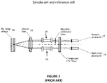
- FIG. 2 An example of a prior art system used for liquid chromatography (LC) is shown in figure 2 .
- Standard UV light sources such as a mercury (Hg) lamp 20
- Hg mercury
- Figure 2 shows that the light source may have to be split using a lens 22, resulting in a reduced light output of the source 20.
- the light source 20 may be split in order to go through a sample material 24 and a reference material 26 and the remaining light is then detected by a sample photocell 27 and a reference photocell 28 respectively.
- New light sources may have been proposed that are more stable and produce less noise compared to standard UV light sources.
- LEDs light-emitting diodes
- They have gained interest due to their long life, high stability, bright output and low power requirement. Additionally, they are small in size and more compact compared to standard light sources. Considering the nearly monochromatic behavior of LEDs, a monochromator is not required.
- An LED-based detector may be fabricated without using expensive optical lenses.
- FIG 3 is a block diagram of an LC detection system that uses an LED 30 as a light source.
- the UV range is desirable because many compounds that may be analyzed by LC exhibit absorption in that range.
- the prior art shows that light from a flat window LED 30 may be directly focused onto a flow-through cell and detection achieved using a signal photodiode 32.
- the detector 32 suffered from high noise, high detection limits and limited linearity.
- the system may have also suffered from high stray light levels.
- One problem with the LC detection system may be that silicon photodiodes 32 may be more sensitive at higher wavelengths than the UV, which may be evident from a photodiode sensitivity plot.
- any light emission from an LED 30 at wavelengths higher than the UV may lead to significant stray light in the system.
- the system shown in figure 3 still required a beam splitter 33 which sent a portion of the light from the LED 30 to a reference diode 36. The other portion of the light was sent through a slit 34 and through a fused silica tubing 35.
- the detector 32 and the reference diode 36 were coupled as inputs to an amplifier 37.
- Another prior art system used a hemispherical lens LED as a light source with a photomultiplier tube for on-capillary detection. This system may have suffered from a high level of stray light, which compromised the linear range and detection limits of the system.
- Capillary columns have gained popularity in LC work, but a detector is needed that can fulfill the detection requirements for such columns.
- a prior art LC detection system using an Hg pen-ray lamp-based detector for on-capillary detection achieved good performance.
- commercial flow-cell based detectors may have introduced considerable dead volume for capillary columns.
- low-volume flow cells (few nLs) may be expensive and suffer from clogging problems due to salt deposition.
- US 5 124 020 A discloses a system for the monitoring of UV-light transmitted through a capillary, e.g. for use as HPLC detector.
- One method of narrow focusing of light in order to eliminate stray light may be to use slits equal to or less than the capillary column internal diameter.
- the use of a slit in front of the capillary column also reduces the light throughput as shown in figure 3 .
- a decrease in light intensity from the light source may decrease the S/N ratio of the detector.
- US 2008304048 A1 discloses the use of UV-LEDs for performing absorption measurements.
- CN 103529008 A discloses the structure of a LED-based light source for focusing blue light on a microfluidic chip.
- the present invention is a system and method for performing UV LED-based absorption detection for capillary liquid chromatography for detecting and quantifying compounds in a liquid, wherein a simplified system eliminates the need for a beam splitter and a reference cell by using a stable UV source, and power requirements are reduced, resulting in a portable and substantially smaller system with relatively low detection limits.
- on-column detection may refer to when packed bed material terminates before the end of the column so that the last part of the column is actually empty. But there may also be situations in which the column has packed bed material all the way to the end of the column and a capillary has to be added in order to perform detection in the capillary portion. Accordingly, the embodiments of the invention should all be considered to include both configurations to be within the scope of all embodiments, where detection is taking place on-column in an area of the column that does not contain packed bed material, or within a capillary that has been added to the very end of the column where the packed bed material ends.
- a first embodiment is an LED-based UV absorption detector with low detection limits for use with capillary liquid chromatography.
- an LED light source may be selected.
- the LED output wavelength may change with changes in drive current and junction temperature. Therefore, LEDs should be driven by a constant current supply, and heating of the system should be avoided.
- the quasi-monochromaticity of the LED source contributes to stray light in the system, leading to detector non-linearity.
- the detection system should be protected from any LED light outside the desired absorption band by employing a filter in the system.
- On-column capillary detection may be preferred for capillary columns, since narrow peak widths are obtained by eliminating extra-column band dispersion, and peak resolution is maintained.
- the short-term noise in the detector may determine the detection limits and may be generally reduced by performing integration, smoothing, and/or using low-pass RC filters.
- the first embodiment shows that UV LED-based absorption detectors have great potential for miniaturization for field analysis. Further optimization of the detector design and reduction in the noise level may lead to better detection limits for small diameter capillary columns.
- the first embodiment resulted in a hand-portable 260 nm LED based UV absorption detector specifically for capillary LC on-column detection.
- the system is relatively small, light-weight and has very low power consumption compared to the prior art.
- FIG. 4 is a first schematic diagram for introducing the elements of the first embodiment of the invention.
- the elements include a UV-based LED 40, a first ball lens 42, a band-pass filter 46 that is tuned to the LED 40 light source, a second ball lens 48, a slit 50 comprised of razor blades, a capillary column 52 that may have an inner diameter (ID) of approximately 150 ⁇ m and an outer diameter of approximately 365 ⁇ m, and a silicon photodiode detector 54.
- ID inner diameter
- ID silicon photodiode detector
- the scale of the elements of the invention are not shown in figure 4 .
- the UV light from the second ball lens 48 may be converging much more sharply than shown.
- the diameter of the second ball lens 48 may be more than 10 times larger than the inner diameter of the capillary column 54. Accordingly, it should be understood that figures 3 and 4 are provided to show the physical order of the components of the invention without showing the actual sizes.
- first and second ball lens 42, 48 are shown in figure 4 , a different type of lens may be substituted and should still be considered to fall within the scope of the first embodiment. It may also be possible to provide the functionality of the first two ball lenses using a single lens and obtain the desired focusing effect. It should also be understood that the values to be given for all aspects of the first embodiment are approximate only and may vary up to 50% without departing from the desired functionality of the first embodiment.
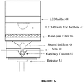
- Figure 5 is a cut-away profile view of the first embodiment shown with more construction detail. This system shown in figure 5 should not be considered as limiting of the invention, but as a demonstration of the principles of the first embodiment. Accordingly, specific values given for size, shape, weight, power, sensitivity or any other characteristics of components of the first embodiment are for example only and may vary from the values given.
- Figure 5 shows an LED 40 having a first ball lens 42.
- the LED 40 may be disposed within an LED holder 44.
- the LED 40 may be manufactured as integrated with the first ball lens 42, or it may be attached or disposed adjacent to the first ball lens 42 after manufacturing.
- the LED 40 may be selected from any desired bandwidth of UV light that is appropriate for the compounds being analyzed in the capillary column 52.
- the first embodiment uses a 260 nm LED 40, but this wavelength of UV light may be changed as desired.
- a commercially available 260 nm UV LED 40 with a first ball lens 42 was used as a light source.
- the LED 40 was mounted on the LED holder 44.
- the LED holder 44 was threaded into a black lens tube and held tight with the help of retaining rings.
- the first ball lens 42 may be 6 mm in diameter, or any appropriate size to focus the light from the LED 40.
- the first embodiment includes a band-pass filter 46 disposed after the first ball lens 42.
- the band-pass filter 46 may be a 260 nm band-pass filter used to reduce stray light from reaching a detector from the LED 40 and/or any surrounding light.
- the value of the band-pass filter may be adjusted as needed in order to be optimized for the LED 40 light source.
- a 260 nm band-pass filter may be positioned in between the LED 40 and the second ball lens 42 in the black threaded tube.
- Another element of the first embodiment may be the use of a second ball lens 48 disposed after the band-pass filter 46.
- the function of the second ball lens 48 may be to receive the UV light that is focused by the first ball lens 42 and focus the UV light even further. It is desirable to focus the UV light so that the light sent into the capillary column 52 may be equal to or smaller than the width of the inside diameter (ID). While it is preferred, the focusing of the UV light source may not be equal to or smaller than the ID of the capillary column 52 in the first embodiment.
- a fused silica ball lens may have a 3 mm diameter for the second ball lens 48 and may be mounted on a 3 mm ball lens disk and may be disposed at the LED focal point.
- the second ball lens mount may be centered on a mount, which may be threaded into the black lens tube containing the LED 40 and the band-pass filter 46.
- one or more slits 50 are disposed after the second ball lens 48 and in front of the capillary column 52.
- the slits 50 may be provided by razor blades or any other appropriate device.
- the slits may be approximately 100 ⁇ m in width.
- the UV light that passes through the capillary column 52 is positioned so that it strikes a UV detector 54.
- the UV detector 54 may be any UV sensitive device.
- the UV detector 54 may be a silicon photodiode.
- the photodiode 54 may be disposed on a diode holder with external threads.
- a black cap may be built to thread into the diode holder. This black cap may have a V-shaped groove to hold the capillary column 52 in the center, a central hole to allow light passage, and grooves on opposite sides of the hole to hold the slits in place.
- a pair of razor blades may be used to fabricate the adjustable slit or slits 50.
- the slits 50 may be disposed on opposite sides of the central hole in the cap covering the outer diameter of the capillary column longitudinally.
- an operational amplifier may be used to receive the current from the photodiode and convert it into voltage values.
- An analog-to-digital converter may be used to record the voltage output with a computer or other recording device. It should be understood that a low pass RC filter may be used at the input to the analog-to-digital converter.
- the LED 40 and silicon photodiode detector 54 may require 6 V and 12 V DC power, respectively, for operation.
- the detector 54 required 0.139 Amp current, and could operate for approximately 25 hours using a 4 Amp-hour 12 V DC battery, as well as operate from line power with an AC to DC adapter.
- the detection system of the first embodiment may operate using a DC power source and therefore may be portable not only because of the DC power requirements, but because of the relatively small dimensions of the detection system.
- Detector noise was determined over 1-min measurements of baseline data.
- a hollow fused silica capillary was connected to a nano-flow pumping system and filled with water. The baseline was then recorded for approximately 1 min, and the peak-to-peak absorbance was calculated. This gave the peak-to-peak (p-p) noise.
- Short term noise (RMS) was calculated as the standard deviation of the recorded baseline.
- the LED 40 was turned off and the dark noise was measured as the standard deviation in the baseline.
- digitizer noise the positive and negative terminals of the A/D converter were shorted.
- Detector drift was determined by flowing water through the capillary at 300 nL/min and recording the baseline for 1 h, followed by measuring the slope of the baseline.
- the smoothing function may be performed in hardware at a faster rate and may be substituted for the software smoothing.
- the smoothing technique used in the first embodiment is fixed window averaging.
- Other smoothing techniques that may be used include but should not be considered as limited to, smoothing by averaging over a sliding window of fixed width, smoothing using an exponentially weighted moving average, and smoothing using a causal or non-causal filter constructed to whiten the baseline noise process.
- the S/N ratio was determined at different smoothing rates, and the best smoothing rate was used for further work.
- the effect of RC filters (time constants of 0.5 s and 1 s) on short-term noise was also studied with and without performing any smoothing.
- a black ink-filled capillary was used for stray light assessment in the system. The stray light level was measured by dividing the voltage signal obtained for black-ink conditions by the voltage signal obtained with a water-filled capillary column 52, multiplied by 100.
- Solutions of different concentrations of sodium anthraquinone-2-sulfonate (SAS), adenosine-5- monophosphate (AMP), DL-tryptophan (DLT) and phenol were made in HPLC grade water. Solutions were made to flow, under nitrogen pressure, through a capillary inserted into the detector 54. Baseline data were recorded before and after each concentration experiment by flowing water through the capillary. Baseline corrected maximum absorbance unit (AU) values were plotted against molar concentrations (M) to determine the linearity of the detector 54. Detection limits for flow-through experiments were reported as 3 times the standard deviation in the baseline. Log-log plots were used to determine the sensitivity of the detector 54.
- SAS sodium anthraquinone-2-sulfonate
- AMP adenosine-5- monophosphate
- DLT DL-tryptophan
- phenol phenol
- Isocratic separations of phenols were performed using a PEGDA monolithic capillary column 52 (16.5 cm ⁇ 150 ⁇ m ID) using the integrated system.
- the pretreated capillary column 52 was filled with monomer mixture and subjected to UV-initiated polymerization for 5 min. After polymerization, the monolithic column was washed with methanol followed by water for at least 6 h to remove unreacted compounds.
- the monomer mixture composition was: DMPA (0.002 g), PEGDA 700 (0.2 g), dodecanol (0.15 g), decanol (0.15 g), decane (0.2 g) and tergitol 15-S-20 (0.3 g).
- the phenolic compounds were dissolved in HPLC water and the mobile phase was 80/20 % (v/v) acetonitrile/water mixture. Separations were performed at 350 nL/min.
- the UV LED-based absorption detector 54 may be much smaller than an earlier described Hg pen-ray lamp-based detector. For on-capillary column detection, absorbance values may be small, so noise reduction may be important to obtaining good detection limits. A bright light source LED 40 may increase the photocurrents used to calculate absorbances without proportional increase in noise. A single wavelength (260 nm) detector 54 was fabricated instead of a multi-wavelength detector in order to reduce the cost and size of the detection system.
- the LED 40 had an integrated fused silica first ball lens 42 (6.35 mm diameter), which focused the light beam down to a 1.5-2.0 mm spot at the focal point (15-20 mm), this was still too broad for the capillary column 52 dimensions (0.075 to 0.20 mm ID). Therefore, the second fused silica ball lens 48 (3 mm diameter) was placed at the focal point of the LED 40 to obtain improved focusing of the light.
- the first and the second ball lenses 42, 48 may be constructed of any appropriate material.
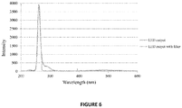
- the LED 40 was selected to emit light with a bandwidth of ⁇ 5 nm; however, with a spectrometer, it was determined that the LED emitted light at higher wavelengths as well. The additional wavelengths of light may have contributed significantly to the stray light of the system.
- a 260 nm band-pass filter with a FWHM of 20 nm was used during experimentation.
- the overlaid spectra in figure 6 show the light output from the LED 40 with and without the filter, confirming that the filter successfully eliminated the light from higher wavelengths.
- the LED 40 position was optimized to obtain the best focus at the center of the capillary column 52.
- a feature of the first embodiment that is part of the functionality of the detector 54 is to perform processing of the detection data.
- the short-term RMS noise of the detector 54 was found to be 8 mV without the use of signal smoothing and low pass filter.
- the dark RMS noise without smoothing was calculated to be 6.95 mV.
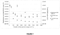
- Software smoothing reduced the dark RMS noise level to 74.4 ⁇ V as shown in figure 7 .
- the dark voltage values were the same in a lighted and dark room, confirming that the capillary column 52 did not act as a light guide.
- Digitizer noise can contribute significantly to the minimum noise obtainable with a detector.
- the digitizer RMS and p-p noise were found to be 2.4 mV and 7.7 mV, respectively.
- the effect of software smoothing on the digitizer RMS noise was studied as shown in figure 7 and the minimum RMS and p-p noise levels obtained were 15 ⁇ V and 95 ⁇ V, respectively.
- dark current noise which includes noise from the photodiode and amplifier, and digitizer noise both contributed to the total baseline noise, and both were effectively reduced using software smoothing of the first embodiment.
- the unaveraged RMS noise level dropped to 2.42 mV and 2.3 mV, respectively.
- the effect of software smoothing on the S/N ratio was also studied and, while it was found that the effect of smoothing on the signal intensity for peak widths in the chromatogram was negligible, the RMS noise level was reduced to a level of 0.18 mV in the voltage corresponding to intensity of incident light (lo) (5.7 ⁇ AU) without the use of a filter. With a 0.5 s filter and 4200 data points per 0.1 s smoothing, the RMS noise further dropped to 0.14 mV (4.4 ⁇ AU). Thus, the LED detector RMS noise was an order of magnitude lower ( ⁇ 10-6 AU) than previous detectors and other UV LED detectors ( ⁇ 10-5 AU). The detector 54 drift was found to be very low (10-5 AU per h), which may be negligible over a peak width and may present no problems for the duration of a typical chromatogram.
- the RMS noise level decreased as the number of data points averaged per 0.1 s was increased from 100 to 2400; however, further decrease in the noise level after 2400 data points smoothing was not significant.
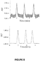
- the S/N ratio for uracil increased from 14 (without smoothing) to 408 (with 4200 data points smoothing) as shown in figure 8 . Due to the reported and observed low drift and inherent light stability of the LED, a reference cell was not included, simplifying the detector 54 design of the first embodiment without compromising its performance.
- the photodiode signal through the capillary column 52 (an average of 70 ⁇ A) was three orders of magnitude higher than previous work (nA range).
- the slit 50 width was adjusted to be equal to the internal diameter of the capillary column 52 (i.e., 150 ⁇ m)
- the stray light level was measured to be 17.3%.
- the slit 50 width was reduced to 100 ⁇ m, which reduced the stray light level to 3.6%.
- a decrease in light intensity was compensated for by increasing the driving current on the LED 40 (13.3 mA). Therefore, the output voltage signal intensity was not compromised at all by a reduction in the slit 50 width.
- the LED 40 was operated at only half of its maximum operating current.
- the maximum absorbance of the detector 54 with the capillary was calculated to be 1.4 AU, which is higher than the value obtained with the Hg pen-ray lamp detector (0.94 AU).
- the linearity of a UV absorption detector may be compromised by improper focusing of the light source on the ID of the capillary column 54.
- Limits of detection depend on detector 54 short-term noise and the test analyte molar absorptivity. For the experiment, selection of test analytes was based on molar absorptivities and relevant previous LED detector work. The detector 54 gave a linear response up to the highest concentration tested, confirming that stray light was low in the system. The linear dynamic range was three orders of magnitude for all of the test analytes.
- the limit of detection at a S/N ratio of 3 was found experimentally to be 24.6 nM (7.63 ppb) or 1.5 fmol for SAS. This detection limit may be five times lower than a prior art pen-ray Hg lamp-based detector.
- this detection limit is also three times lower than the non-referenced single-wavelength flow cell-based (1 cm long) detection limit reported earlier.
- the detection limits for AMP (87.9 nM or 30.5 ppb) would be 230 times lower for the same capillary column 54 dimensions (75 ⁇ m ID) than a non-referenced LED detector reported earlier.
- the detection limit at an S/N ratio of 3 was found to be 299 nM (61 ppb) or 17.9 fmol. This detection limit would be 60 times lower than the referenced detector reported earlier for the same capillary dimensions (250 ⁇ m ID.
- the variations in detection limits for the various compounds is consistent with the variations in molar absorptivities at 260 nm.
- the detection limits for the detector 54 are remarkable considering the fact that detection was performed on the capillary scale.
- the calibration data for SAS, AMP and DLT are listed in Table 1.
- the detection system includes a system for analyzing absorption of the UV light by at least one compound disposed in a liquid within the capillary column by analyzing the UV light that is received by the detector.
- the system for analyzing absorption may be part of the detector or may be a computer system that is coupled to the detection system for receiving data from the detector.
- the first embodiment performs on-column LC detection using a monolithic capillary column.
- Using on-column detection may improve peak shapes and increase detection sensitivity because extra-column band broadening may be reduced.
- the first embodiment may be a highly sensitive on-column detector 54 fabricated using a 260 nm UV LED 40 that can detect in the ppb range.
- the noise level of the detector 54 was remarkably reduced by the use of software smoothing and a low pass filter, i.e., 3.4-4.4 ⁇ AU, which is among the lowest noise levels ever attained with absorption detectors designed for capillary column 52 work.
- the low detection limits may be attributed to good light focusing, low stray light, and very low noise in the system.
- the low detection limits of the first embodiment may be obtained for the test compounds due to the good light focusing, low stray light and very low noise in the capillary LC system.
- the detection limits for SAS in the capillary format with 150 ⁇ m pathlength may be 3 times lower than the LED-based detector with 1 cm pathlength.
- the detection limits were improved by a factor of 230 and 60 in comparison with the detectors with the same pathlength.
- phenol detection limits in our detector were the same under flow-through experiments and under separation conditions. Thus, detector performance was not compromised under actual liquid chromatography work. Reproducible isocratic separation of a phenol mixture was also demonstrated.
- a final comment regarding the size, weight, power requirements and portability of the first embodiment are a direct result of the uncomplicated design of the capillary LC system.
- a typical commercial system may have size dimensions of 11 x 13 x 22 cm, have a weight of 3.3 lbs., require a regular AC power line, and have a sensitivity that is approximately 1 mAU.
- the first embodiment may have dimensions that are approximately 5.2 x 3 x 3 cm, may have a weight of 0.2 Ibs., may operate from a 12 DC power source and only use 1 .68 W, and may have a sensitivity of approximately 10 ⁇ AU. It should be understood that these values are approximate only and may vary up to 50% without departing from the characteristics of the first embodiment.
Applications Claiming Priority (2)
| Application Number | Priority Date | Filing Date | Title |
|---|---|---|---|
| US201461996803P | 2014-05-15 | 2014-05-15 | |
| PCT/US2015/031023 WO2015175906A1 (en) | 2014-05-15 | 2015-05-15 | Low-power miniature led-based uv absorption detector with low detection limits for capillary liquid chromatography |
Publications (3)
| Publication Number | Publication Date |
|---|---|
| EP3142765A1 EP3142765A1 (en) | 2017-03-22 |
| EP3142765A4 EP3142765A4 (en) | 2018-01-17 |
| EP3142765B1 true EP3142765B1 (en) | 2019-08-14 |
Family
ID=54480760
Family Applications (1)
| Application Number | Title | Priority Date | Filing Date |
|---|---|---|---|
| EP15793306.0A Active EP3142765B1 (en) | 2014-05-15 | 2015-05-15 | Low-power miniature led-based uv absorption detector with low detection limits for capillary liquid chromatography |
Country Status (7)
| Country | Link |
|---|---|
| US (1) | US10060889B2 (zh) |
| EP (1) | EP3142765B1 (zh) |
| JP (1) | JP6804436B2 (zh) |
| CN (1) | CN106536011B (zh) |
| AU (1) | AU2015259004B2 (zh) |
| CA (1) | CA2949213C (zh) |
| WO (1) | WO2015175906A1 (zh) |
Families Citing this family (10)
| Publication number | Priority date | Publication date | Assignee | Title |
|---|---|---|---|---|
| GB2539504B (en) * | 2015-06-19 | 2019-04-17 | Aqua21 Ltd | Absorption Sensor for Measuring Substance Concentration |
| US20180231511A1 (en) * | 2015-08-18 | 2018-08-16 | Shimadzu Corporation | Detector for liquid chromatography |
| AT518576B1 (de) * | 2016-04-18 | 2018-07-15 | Scan Messtechnik Gmbh | Spektrometer |
| NL2019122A (en) | 2016-06-30 | 2018-01-09 | Asml Holding Nv | Adaptive filter for in-line correction |
| AU2018226905A1 (en) * | 2017-03-03 | 2019-09-12 | Brigham Young University | Multi-modal, multi-detector liquid chromatographic system |
| JP2020521129A (ja) * | 2017-05-18 | 2020-07-16 | ブリガム・ヤング・ユニバーシティBrigham Young University | キャピラリー分離技法使用後のオンカラム検出用の統合された蛍光/吸光検出器 |
| CN108562540A (zh) * | 2017-12-29 | 2018-09-21 | 深圳市华星光电技术有限公司 | 光学测试装置 |
| JP7074305B2 (ja) * | 2018-06-01 | 2022-05-24 | アクアモニトリックス リミテッド | 無機分析物を検出するための光学検出セルおよびシステム |
| JP7235298B2 (ja) | 2019-03-20 | 2023-03-08 | 株式会社日立ハイテクサイエンス | クロマトグラフのデータ処理装置、データ処理方法、およびクロマトグラフ |
| CN110047519B (zh) * | 2019-04-16 | 2021-08-24 | 广州大学 | 一种语音端点检测方法、装置及设备 |
Family Cites Families (25)
| Publication number | Priority date | Publication date | Assignee | Title |
|---|---|---|---|---|
| US4927265A (en) | 1988-04-29 | 1990-05-22 | 501 Microphoretic Systems, Inc. | Detector for fluorescence and absorption spectroscopy |
| US5124020A (en) | 1989-09-26 | 1992-06-23 | Rutgers, The State University | Adjustable height and width aperture for capillary photodetector cell |
| JPH04115084U (ja) * | 1991-03-26 | 1992-10-12 | 九州電機製造株式会社 | 電気自動車用電池残存容量計 |
| US5235409A (en) * | 1991-08-13 | 1993-08-10 | Varian Associates, Inc. | Optical detection system for capillary separation columns |
| DE69230863T2 (de) * | 1991-12-03 | 2000-07-27 | Applied Biosystems | Kapillare durchflusszelle zum nachweis mehrerer wellenlängen |
| EP0616211B1 (en) * | 1993-03-18 | 1999-01-13 | Novartis AG | Optical detection arrangement for small volume chemical analysis of fluid samples |
| US5533063A (en) * | 1994-01-31 | 1996-07-02 | The Regents Of The University Of California | Method and apparatus for multipath channel shaping |
| EP0821788B1 (en) * | 1996-02-20 | 2006-02-01 | Waters Investments Limited | Capillary electrophoresis detector apparatus |
| US6788414B1 (en) | 1999-09-09 | 2004-09-07 | Iowa State University Research Foundation, Inc. | Method of analyzing multiple sample simultaneously by detecting absorption and systems for use in such a method |
| AU2002247040A1 (en) | 2001-01-26 | 2002-08-06 | Biocal Technology, Inc. | Multi-channel bio-separation cartridge |
| US20030110840A1 (en) * | 2001-07-24 | 2003-06-19 | Arriaga Edgar A. | Systems and methods for detecting a particle |
| US7122799B2 (en) * | 2003-12-18 | 2006-10-17 | Palo Alto Research Center Incorporated | LED or laser enabled real-time PCR system and spectrophotometer |
| US20060019265A1 (en) * | 2004-04-30 | 2006-01-26 | Kimberly-Clark Worldwide, Inc. | Transmission-based luminescent detection systems |
| US7497937B2 (en) * | 2004-09-03 | 2009-03-03 | Combisep, Inc. | Microfabricated chip and method of use |
| CN1755351A (zh) * | 2004-09-30 | 2006-04-05 | 中国科学院大连化学物理研究所 | 发光二极管诱导荧光微型检测器 |
| GB0524225D0 (en) * | 2005-11-29 | 2006-01-04 | Amersham Biosciences Ab | Methods and apparatus for detecting and measuring the concentration of a substance in a solution |
| US8137626B2 (en) * | 2006-05-19 | 2012-03-20 | California Institute Of Technology | Fluorescence detector, filter device and related methods |
| US7846391B2 (en) | 2006-05-22 | 2010-12-07 | Lumencor, Inc. | Bioanalytical instrumentation using a light source subsystem |
| US8467059B2 (en) * | 2006-10-27 | 2013-06-18 | University Of South Florida | Deep-UV LED and laser induced fluorescence detection and monitoring of trace organics in potable liquids |
| US7835000B2 (en) * | 2006-11-03 | 2010-11-16 | Los Alamos National Security, Llc | System and method for measuring particles in a sample stream of a flow cytometer or the like |
| US8098375B2 (en) * | 2007-08-06 | 2012-01-17 | Lumencor, Inc. | Light emitting diode illumination system |
| JP2009080001A (ja) * | 2007-09-26 | 2009-04-16 | Fujitaro Imasaka | ガスクロマトグラフ質量分析法におけるデータ処理方法 |
| US20100324830A1 (en) * | 2009-06-22 | 2010-12-23 | Solie John B | Handheld optical sensor for measuring the normalized difference vegetative index in plants |
| WO2013181362A1 (en) | 2012-06-01 | 2013-12-05 | Advanced Analytical Technologies, Inc. | Multi-color detection system for multiplexed capillary electrophoresis |
| CN103529006B (zh) * | 2013-10-18 | 2016-08-17 | 大连海事大学 | 一种基于微流控芯片的便携式荧光检测装置 |
-
2015
- 2015-05-15 US US14/713,328 patent/US10060889B2/en active Active
- 2015-05-15 WO PCT/US2015/031023 patent/WO2015175906A1/en active Application Filing
- 2015-05-15 AU AU2015259004A patent/AU2015259004B2/en active Active
- 2015-05-15 CA CA2949213A patent/CA2949213C/en active Active
- 2015-05-15 CN CN201580038216.XA patent/CN106536011B/zh active Active
- 2015-05-15 EP EP15793306.0A patent/EP3142765B1/en active Active
- 2015-05-15 JP JP2017512869A patent/JP6804436B2/ja active Active
Non-Patent Citations (1)
| Title |
|---|
| None * |
Also Published As
| Publication number | Publication date |
|---|---|
| JP6804436B2 (ja) | 2020-12-23 |
| AU2015259004B2 (en) | 2018-11-08 |
| EP3142765A1 (en) | 2017-03-22 |
| CN106536011A (zh) | 2017-03-22 |
| CN106536011B (zh) | 2019-08-20 |
| JP2017516120A (ja) | 2017-06-15 |
| WO2015175906A1 (en) | 2015-11-19 |
| US20150330955A1 (en) | 2015-11-19 |
| CA2949213A1 (en) | 2015-11-19 |
| CA2949213C (en) | 2022-07-12 |
| AU2015259004A1 (en) | 2016-12-01 |
| EP3142765A4 (en) | 2018-01-17 |
| US10060889B2 (en) | 2018-08-28 |
Similar Documents
| Publication | Publication Date | Title |
|---|---|---|
| EP3142765B1 (en) | Low-power miniature led-based uv absorption detector with low detection limits for capillary liquid chromatography | |
| US11513006B2 (en) | Systems and methods for an absorbance detector with optical reference | |
| US7319522B2 (en) | Systems and methods for in situ spectroscopic measurements | |
| US3920334A (en) | Dual purpose detector for a liquid chromatograph | |
| Sharma et al. | LED-based UV absorption detector with low detection limits for capillary liquid chromatography | |
| US20150260693A1 (en) | Multi-measurement flow cell assembly for liquid chromatography | |
| US20160231232A1 (en) | Optical absorption monitor system | |
| Bui et al. | Absorbance detector based on a deep UV light emitting diode for narrow‐column HPLC | |
| WO2016206355A1 (zh) | 基于ccd的紫外毛细管柱上检测仪 | |
| Schmid et al. | UV-absorbance detector for HPLC based on a light-emitting diode | |
| Bui et al. | Molecular absorption measurements with an optical fibre coupled array of ultra-violet light-emitting diodes | |
| Hemida et al. | Recent advances in miniaturization of portable liquid chromatography with emphasis on detection | |
| Šesták et al. | Compact optical detector utilizing light emitting diodes, 50 nL L-shaped silica capillary cell and CCD spectrometer for simultaneous multi-wavelength monitoring of absorbance and fluorescence in microcolumn liquid chromatography | |
| US20180335408A1 (en) | Combined fluorescence and absorption detector for on-column detection after capillary separation techniques | |
| WO2005119216A1 (en) | Systems and methods for in situ spectroscopic measurements | |
| Dang et al. | A miniaturized and high sensitive dual channel fluorimeter based on compact collinear optical arrangement | |
| Renn et al. | Single optical fiber, position-sensitive detector-based multiwavelength absorbance spectrophotometer | |
| WO2014146147A2 (en) | Multi-measurement flow cell assembly for liquid chromatography | |
| Kubala et al. | Design and performance of a direct-reading, multichannel spectrometer for the determination of chlorinated purgeable organic compounds by flame infrared-emission spectrometry | |
| Kaltenbach | A high-sensitivity diode array detector for on-column detection in capillary electrophoresis | |
| JP2016038303A (ja) | 液体分析装置 | |
| Venn | Hplc detectors | |
| Rao et al. | Inline Detectors |
Legal Events
| Date | Code | Title | Description |
|---|---|---|---|
| STAA | Information on the status of an ep patent application or granted ep patent |
Free format text: STATUS: THE INTERNATIONAL PUBLICATION HAS BEEN MADE |
|
| PUAI | Public reference made under article 153(3) epc to a published international application that has entered the european phase |
Free format text: ORIGINAL CODE: 0009012 |
|
| STAA | Information on the status of an ep patent application or granted ep patent |
Free format text: STATUS: REQUEST FOR EXAMINATION WAS MADE |
|
| 17P | Request for examination filed |
Effective date: 20161114 |
|
| AK | Designated contracting states |
Kind code of ref document: A1 Designated state(s): AL AT BE BG CH CY CZ DE DK EE ES FI FR GB GR HR HU IE IS IT LI LT LU LV MC MK MT NL NO PL PT RO RS SE SI SK SM TR |
|
| AX | Request for extension of the european patent |
Extension state: BA ME |
|
| DAV | Request for validation of the european patent (deleted) | ||
| DAX | Request for extension of the european patent (deleted) | ||
| A4 | Supplementary search report drawn up and despatched |
Effective date: 20171219 |
|
| RIC1 | Information provided on ipc code assigned before grant |
Ipc: G01N 21/03 20060101ALN20171213BHEP Ipc: G01N 21/33 20060101ALI20171213BHEP Ipc: G01N 30/74 20060101AFI20171213BHEP |
|
| RIC1 | Information provided on ipc code assigned before grant |
Ipc: G01N 21/33 20060101ALI20181221BHEP Ipc: G01N 21/03 20060101ALN20181221BHEP Ipc: G01N 30/74 20060101AFI20181221BHEP |
|
| REG | Reference to a national code |
Ref country code: DE Ref legal event code: R079 Ref document number: 602015035919 Country of ref document: DE Free format text: PREVIOUS MAIN CLASS: B01D0015080000 Ipc: G01N0030740000 |
|
| RIC1 | Information provided on ipc code assigned before grant |
Ipc: G01N 30/74 20060101AFI20190124BHEP Ipc: G01N 21/33 20060101ALI20190124BHEP Ipc: G01N 21/03 20060101ALN20190124BHEP |
|
| RIC1 | Information provided on ipc code assigned before grant |
Ipc: G01N 21/33 20060101ALI20190204BHEP Ipc: G01N 21/03 20060101ALN20190204BHEP Ipc: G01N 30/74 20060101AFI20190204BHEP |
|
| GRAP | Despatch of communication of intention to grant a patent |
Free format text: ORIGINAL CODE: EPIDOSNIGR1 |
|
| STAA | Information on the status of an ep patent application or granted ep patent |
Free format text: STATUS: GRANT OF PATENT IS INTENDED |
|
| INTG | Intention to grant announced |
Effective date: 20190318 |
|
| GRAS | Grant fee paid |
Free format text: ORIGINAL CODE: EPIDOSNIGR3 |
|
| GRAA | (expected) grant |
Free format text: ORIGINAL CODE: 0009210 |
|
| STAA | Information on the status of an ep patent application or granted ep patent |
Free format text: STATUS: THE PATENT HAS BEEN GRANTED |
|
| AK | Designated contracting states |
Kind code of ref document: B1 Designated state(s): AL AT BE BG CH CY CZ DE DK EE ES FI FR GB GR HR HU IE IS IT LI LT LU LV MC MK MT NL NO PL PT RO RS SE SI SK SM TR |
|
| REG | Reference to a national code |
Ref country code: GB Ref legal event code: FG4D |
|
| REG | Reference to a national code |
Ref country code: CH Ref legal event code: EP Ref country code: AT Ref legal event code: REF Ref document number: 1167636 Country of ref document: AT Kind code of ref document: T Effective date: 20190815 |
|
| REG | Reference to a national code |
Ref country code: IE Ref legal event code: FG4D |
|
| REG | Reference to a national code |
Ref country code: DE Ref legal event code: R096 Ref document number: 602015035919 Country of ref document: DE |
|
| REG | Reference to a national code |
Ref country code: NL Ref legal event code: FP |
|
| REG | Reference to a national code |
Ref country code: NO Ref legal event code: T2 Effective date: 20190814 |
|
| REG | Reference to a national code |
Ref country code: LT Ref legal event code: MG4D |
|
| PG25 | Lapsed in a contracting state [announced via postgrant information from national office to epo] |
Ref country code: FI Free format text: LAPSE BECAUSE OF FAILURE TO SUBMIT A TRANSLATION OF THE DESCRIPTION OR TO PAY THE FEE WITHIN THE PRESCRIBED TIME-LIMIT Effective date: 20190814 Ref country code: PT Free format text: LAPSE BECAUSE OF FAILURE TO SUBMIT A TRANSLATION OF THE DESCRIPTION OR TO PAY THE FEE WITHIN THE PRESCRIBED TIME-LIMIT Effective date: 20191216 Ref country code: SE Free format text: LAPSE BECAUSE OF FAILURE TO SUBMIT A TRANSLATION OF THE DESCRIPTION OR TO PAY THE FEE WITHIN THE PRESCRIBED TIME-LIMIT Effective date: 20190814 Ref country code: HR Free format text: LAPSE BECAUSE OF FAILURE TO SUBMIT A TRANSLATION OF THE DESCRIPTION OR TO PAY THE FEE WITHIN THE PRESCRIBED TIME-LIMIT Effective date: 20190814 Ref country code: LT Free format text: LAPSE BECAUSE OF FAILURE TO SUBMIT A TRANSLATION OF THE DESCRIPTION OR TO PAY THE FEE WITHIN THE PRESCRIBED TIME-LIMIT Effective date: 20190814 Ref country code: BG Free format text: LAPSE BECAUSE OF FAILURE TO SUBMIT A TRANSLATION OF THE DESCRIPTION OR TO PAY THE FEE WITHIN THE PRESCRIBED TIME-LIMIT Effective date: 20191114 |
|
| REG | Reference to a national code |
Ref country code: AT Ref legal event code: MK05 Ref document number: 1167636 Country of ref document: AT Kind code of ref document: T Effective date: 20190814 |
|
| PG25 | Lapsed in a contracting state [announced via postgrant information from national office to epo] |
Ref country code: ES Free format text: LAPSE BECAUSE OF FAILURE TO SUBMIT A TRANSLATION OF THE DESCRIPTION OR TO PAY THE FEE WITHIN THE PRESCRIBED TIME-LIMIT Effective date: 20190814 Ref country code: IS Free format text: LAPSE BECAUSE OF FAILURE TO SUBMIT A TRANSLATION OF THE DESCRIPTION OR TO PAY THE FEE WITHIN THE PRESCRIBED TIME-LIMIT Effective date: 20191214 Ref country code: RS Free format text: LAPSE BECAUSE OF FAILURE TO SUBMIT A TRANSLATION OF THE DESCRIPTION OR TO PAY THE FEE WITHIN THE PRESCRIBED TIME-LIMIT Effective date: 20190814 Ref country code: LV Free format text: LAPSE BECAUSE OF FAILURE TO SUBMIT A TRANSLATION OF THE DESCRIPTION OR TO PAY THE FEE WITHIN THE PRESCRIBED TIME-LIMIT Effective date: 20190814 Ref country code: AL Free format text: LAPSE BECAUSE OF FAILURE TO SUBMIT A TRANSLATION OF THE DESCRIPTION OR TO PAY THE FEE WITHIN THE PRESCRIBED TIME-LIMIT Effective date: 20190814 Ref country code: GR Free format text: LAPSE BECAUSE OF FAILURE TO SUBMIT A TRANSLATION OF THE DESCRIPTION OR TO PAY THE FEE WITHIN THE PRESCRIBED TIME-LIMIT Effective date: 20191115 |
|
| PG25 | Lapsed in a contracting state [announced via postgrant information from national office to epo] |
Ref country code: TR Free format text: LAPSE BECAUSE OF FAILURE TO SUBMIT A TRANSLATION OF THE DESCRIPTION OR TO PAY THE FEE WITHIN THE PRESCRIBED TIME-LIMIT Effective date: 20190814 |
|
| PG25 | Lapsed in a contracting state [announced via postgrant information from national office to epo] |
Ref country code: DK Free format text: LAPSE BECAUSE OF FAILURE TO SUBMIT A TRANSLATION OF THE DESCRIPTION OR TO PAY THE FEE WITHIN THE PRESCRIBED TIME-LIMIT Effective date: 20190814 Ref country code: EE Free format text: LAPSE BECAUSE OF FAILURE TO SUBMIT A TRANSLATION OF THE DESCRIPTION OR TO PAY THE FEE WITHIN THE PRESCRIBED TIME-LIMIT Effective date: 20190814 Ref country code: AT Free format text: LAPSE BECAUSE OF FAILURE TO SUBMIT A TRANSLATION OF THE DESCRIPTION OR TO PAY THE FEE WITHIN THE PRESCRIBED TIME-LIMIT Effective date: 20190814 Ref country code: RO Free format text: LAPSE BECAUSE OF FAILURE TO SUBMIT A TRANSLATION OF THE DESCRIPTION OR TO PAY THE FEE WITHIN THE PRESCRIBED TIME-LIMIT Effective date: 20190814 Ref country code: PL Free format text: LAPSE BECAUSE OF FAILURE TO SUBMIT A TRANSLATION OF THE DESCRIPTION OR TO PAY THE FEE WITHIN THE PRESCRIBED TIME-LIMIT Effective date: 20190814 |
|
| PG25 | Lapsed in a contracting state [announced via postgrant information from national office to epo] |
Ref country code: CZ Free format text: LAPSE BECAUSE OF FAILURE TO SUBMIT A TRANSLATION OF THE DESCRIPTION OR TO PAY THE FEE WITHIN THE PRESCRIBED TIME-LIMIT Effective date: 20190814 Ref country code: SK Free format text: LAPSE BECAUSE OF FAILURE TO SUBMIT A TRANSLATION OF THE DESCRIPTION OR TO PAY THE FEE WITHIN THE PRESCRIBED TIME-LIMIT Effective date: 20190814 Ref country code: SM Free format text: LAPSE BECAUSE OF FAILURE TO SUBMIT A TRANSLATION OF THE DESCRIPTION OR TO PAY THE FEE WITHIN THE PRESCRIBED TIME-LIMIT Effective date: 20190814 Ref country code: IS Free format text: LAPSE BECAUSE OF FAILURE TO SUBMIT A TRANSLATION OF THE DESCRIPTION OR TO PAY THE FEE WITHIN THE PRESCRIBED TIME-LIMIT Effective date: 20200224 |
|
| REG | Reference to a national code |
Ref country code: DE Ref legal event code: R097 Ref document number: 602015035919 Country of ref document: DE |
|
| PLBE | No opposition filed within time limit |
Free format text: ORIGINAL CODE: 0009261 |
|
| STAA | Information on the status of an ep patent application or granted ep patent |
Free format text: STATUS: NO OPPOSITION FILED WITHIN TIME LIMIT |
|
| PG2D | Information on lapse in contracting state deleted |
Ref country code: IS |
|
| 26N | No opposition filed |
Effective date: 20200603 |
|
| PG25 | Lapsed in a contracting state [announced via postgrant information from national office to epo] |
Ref country code: SI Free format text: LAPSE BECAUSE OF FAILURE TO SUBMIT A TRANSLATION OF THE DESCRIPTION OR TO PAY THE FEE WITHIN THE PRESCRIBED TIME-LIMIT Effective date: 20190814 |
|
| PG25 | Lapsed in a contracting state [announced via postgrant information from national office to epo] |
Ref country code: MC Free format text: LAPSE BECAUSE OF FAILURE TO SUBMIT A TRANSLATION OF THE DESCRIPTION OR TO PAY THE FEE WITHIN THE PRESCRIBED TIME-LIMIT Effective date: 20190814 Ref country code: CH Free format text: LAPSE BECAUSE OF NON-PAYMENT OF DUE FEES Effective date: 20200531 Ref country code: LI Free format text: LAPSE BECAUSE OF NON-PAYMENT OF DUE FEES Effective date: 20200531 |
|
| PG25 | Lapsed in a contracting state [announced via postgrant information from national office to epo] |
Ref country code: LU Free format text: LAPSE BECAUSE OF NON-PAYMENT OF DUE FEES Effective date: 20200515 |
|
| PG25 | Lapsed in a contracting state [announced via postgrant information from national office to epo] |
Ref country code: IE Free format text: LAPSE BECAUSE OF NON-PAYMENT OF DUE FEES Effective date: 20200515 |
|
| PG25 | Lapsed in a contracting state [announced via postgrant information from national office to epo] |
Ref country code: MT Free format text: LAPSE BECAUSE OF FAILURE TO SUBMIT A TRANSLATION OF THE DESCRIPTION OR TO PAY THE FEE WITHIN THE PRESCRIBED TIME-LIMIT Effective date: 20190814 Ref country code: CY Free format text: LAPSE BECAUSE OF FAILURE TO SUBMIT A TRANSLATION OF THE DESCRIPTION OR TO PAY THE FEE WITHIN THE PRESCRIBED TIME-LIMIT Effective date: 20190814 |
|
| PG25 | Lapsed in a contracting state [announced via postgrant information from national office to epo] |
Ref country code: MK Free format text: LAPSE BECAUSE OF FAILURE TO SUBMIT A TRANSLATION OF THE DESCRIPTION OR TO PAY THE FEE WITHIN THE PRESCRIBED TIME-LIMIT Effective date: 20190814 |
|
| PGFP | Annual fee paid to national office [announced via postgrant information from national office to epo] |
Ref country code: NO Payment date: 20230523 Year of fee payment: 9 Ref country code: NL Payment date: 20230519 Year of fee payment: 9 Ref country code: IT Payment date: 20230526 Year of fee payment: 9 Ref country code: FR Payment date: 20230526 Year of fee payment: 9 Ref country code: DE Payment date: 20230519 Year of fee payment: 9 |
|
| PGFP | Annual fee paid to national office [announced via postgrant information from national office to epo] |
Ref country code: BE Payment date: 20230519 Year of fee payment: 9 |
|
| PGFP | Annual fee paid to national office [announced via postgrant information from national office to epo] |
Ref country code: GB Payment date: 20230524 Year of fee payment: 9 |