EP3142741B1 - Tubular fitting for medical fluid lines - Google Patents
Tubular fitting for medical fluid lines Download PDFInfo
- Publication number
- EP3142741B1 EP3142741B1 EP14777784.1A EP14777784A EP3142741B1 EP 3142741 B1 EP3142741 B1 EP 3142741B1 EP 14777784 A EP14777784 A EP 14777784A EP 3142741 B1 EP3142741 B1 EP 3142741B1
- Authority
- EP
- European Patent Office
- Prior art keywords
- connector
- male
- male connector
- female
- female connector
- Prior art date
- Legal status (The legal status is an assumption and is not a legal conclusion. Google has not performed a legal analysis and makes no representation as to the accuracy of the status listed.)
- Active
Links
- 239000012530 fluid Substances 0.000 title claims description 9
- 230000000295 complement effect Effects 0.000 claims description 15
- 230000008878 coupling Effects 0.000 claims description 8
- 238000010168 coupling process Methods 0.000 claims description 8
- 238000005859 coupling reaction Methods 0.000 claims description 8
- 238000004891 communication Methods 0.000 claims description 6
- 238000007789 sealing Methods 0.000 claims description 4
- 238000005192 partition Methods 0.000 claims description 3
- 230000002093 peripheral effect Effects 0.000 claims description 3
- 230000000694 effects Effects 0.000 description 6
- 230000015572 biosynthetic process Effects 0.000 description 2
- 238000005755 formation reaction Methods 0.000 description 2
- 238000000926 separation method Methods 0.000 description 2
- 238000002512 chemotherapy Methods 0.000 description 1
- 238000010276 construction Methods 0.000 description 1
- 238000001631 haemodialysis Methods 0.000 description 1
- 230000000322 hemodialysis Effects 0.000 description 1
- 230000001939 inductive effect Effects 0.000 description 1
- 230000000414 obstructive effect Effects 0.000 description 1
- 230000002747 voluntary effect Effects 0.000 description 1
Images


Classifications
-
- A—HUMAN NECESSITIES
- A61—MEDICAL OR VETERINARY SCIENCE; HYGIENE
- A61M—DEVICES FOR INTRODUCING MEDIA INTO, OR ONTO, THE BODY; DEVICES FOR TRANSDUCING BODY MEDIA OR FOR TAKING MEDIA FROM THE BODY; DEVICES FOR PRODUCING OR ENDING SLEEP OR STUPOR
- A61M39/00—Tubes, tube connectors, tube couplings, valves, access sites or the like, specially adapted for medical use
- A61M39/10—Tube connectors; Tube couplings
- A61M39/1011—Locking means for securing connection; Additional tamper safeties
-
- A—HUMAN NECESSITIES
- A61—MEDICAL OR VETERINARY SCIENCE; HYGIENE
- A61M—DEVICES FOR INTRODUCING MEDIA INTO, OR ONTO, THE BODY; DEVICES FOR TRANSDUCING BODY MEDIA OR FOR TAKING MEDIA FROM THE BODY; DEVICES FOR PRODUCING OR ENDING SLEEP OR STUPOR
- A61M39/00—Tubes, tube connectors, tube couplings, valves, access sites or the like, specially adapted for medical use
- A61M39/10—Tube connectors; Tube couplings
- A61M39/1055—Rotating or swivel joints
-
- A—HUMAN NECESSITIES
- A61—MEDICAL OR VETERINARY SCIENCE; HYGIENE
- A61M—DEVICES FOR INTRODUCING MEDIA INTO, OR ONTO, THE BODY; DEVICES FOR TRANSDUCING BODY MEDIA OR FOR TAKING MEDIA FROM THE BODY; DEVICES FOR PRODUCING OR ENDING SLEEP OR STUPOR
- A61M39/00—Tubes, tube connectors, tube couplings, valves, access sites or the like, specially adapted for medical use
- A61M39/22—Valves or arrangement of valves
- A61M39/26—Valves closing automatically on disconnecting the line and opening on reconnection thereof
-
- A—HUMAN NECESSITIES
- A61—MEDICAL OR VETERINARY SCIENCE; HYGIENE
- A61M—DEVICES FOR INTRODUCING MEDIA INTO, OR ONTO, THE BODY; DEVICES FOR TRANSDUCING BODY MEDIA OR FOR TAKING MEDIA FROM THE BODY; DEVICES FOR PRODUCING OR ENDING SLEEP OR STUPOR
- A61M39/00—Tubes, tube connectors, tube couplings, valves, access sites or the like, specially adapted for medical use
- A61M39/10—Tube connectors; Tube couplings
- A61M2039/1016—Unlocking means providing a secure or comfortable disconnection
-
- A—HUMAN NECESSITIES
- A61—MEDICAL OR VETERINARY SCIENCE; HYGIENE
- A61M—DEVICES FOR INTRODUCING MEDIA INTO, OR ONTO, THE BODY; DEVICES FOR TRANSDUCING BODY MEDIA OR FOR TAKING MEDIA FROM THE BODY; DEVICES FOR PRODUCING OR ENDING SLEEP OR STUPOR
- A61M39/00—Tubes, tube connectors, tube couplings, valves, access sites or the like, specially adapted for medical use
- A61M39/10—Tube connectors; Tube couplings
- A61M2039/1033—Swivel nut connectors, e.g. threaded connectors, bayonet-connectors
-
- A—HUMAN NECESSITIES
- A61—MEDICAL OR VETERINARY SCIENCE; HYGIENE
- A61M—DEVICES FOR INTRODUCING MEDIA INTO, OR ONTO, THE BODY; DEVICES FOR TRANSDUCING BODY MEDIA OR FOR TAKING MEDIA FROM THE BODY; DEVICES FOR PRODUCING OR ENDING SLEEP OR STUPOR
- A61M2205/00—General characteristics of the apparatus
- A61M2205/02—General characteristics of the apparatus characterised by a particular materials
- A61M2205/0216—Materials providing elastic properties, e.g. for facilitating deformation and avoid breaking
Definitions
- the present invention relates, in general, to medical fluid lines, for example, hemodialysis lines, chemotherapy lines and the like.
- the object of the present invention is to provide a safe and effective solution to this problem, whilst at the same time being practical and functional.
- a fitting for medical fluid lines comprising a hollow body within which a male connector accessible at one end of the body and a female connector accessible at the other end of the body, are coaxially housed.
- the fitting comprises first unidirectional coupling means for locking in rotation the male connector with respect to the body in the direction corresponding to the screwing between said male connector and a complementary female connector of the line, and to enable free rotation of the male connector in the opposite direction, and second unidirectional coupling means for locking in rotation the female connector with respect to the body in the direction corresponding to the screwing between said female connector and a complementary male connector of the line, and to enable free rotation of the female connector in the opposite direction.
- the fitting according to the invention is advantageously usable in the form of an intermediate element for a secure connection between a male connector and a female connector of medical fluid lines.
- these connectors instead of being connected directly to each other, are thus connected indirectly, by means of the fitting according to the invention, which ensures the necessary degree of safety against risks of undesired openings of the medical line due to accidental decoupling or a wrong maneuver between the connectors of the line.
- first and/or second locking means are also provided, designed to be positively operated to lock in rotation the male connector and/or the female connector, respectively, with respect to the body in the aforesaid opposite direction of rotation.
- the male and female connectors can be in communication with each another to define a flow passage through the fitting, or the communication between the male and female connectors can be obstructed.
- the female connector can be a valve connector and the male connector can also be a valve connector.
- the fitting according to a first embodiment of the invention is indicated with I and is tubular. It comprises an outer hollow body 1 of generally cylindrical shape, within which a male connector 2 of the luer lock type and analogues, and a female fitting 3 of the luer lock type and analogues are coaxially housed in an opposite condition.
- the connectors 2 and 3 are rotatably mounted relative to the body 1 and to each another, with the limitations which will be discussed, and have a generally conventional shape.
- the male connector 2 comprises an inner tubular element 4 with a conical outer surface protruding from one end of the body 1, and an internally threaded outer hollow element 5, which extends towards the inside of the body 1 with a hollow appendage 6.
- the female connector 3 consists of an externally threaded tubular element 7 with a conical inner surface, protruding from the other end of the body 1 and integrally formed with an appendage 8 terminating with a shank 9 rotatably inserted within the hollow appendage 6 of the male connector 2.
- the connectors 2 and 3 are locked axially within the body 1, which is conveniently formed from two half-shells coupled together in an interlocking manner, and an O-ring seal 10 is interposed between the shank 9 and the hollow appendage 6.
- the male and female connectors 2, 3 define a free flow passage through the connector according to the invention, and during use are intended to be respectively coupled to a complementary female connector and to a complementary male connector of a medical line.
- the hollow appendage 6 of the male connector 2 and the appendage 8 of the female connector 3 are locked axially within the hollow body 1 and are coupled with this in rotation in one direction and normally freely rotatable in the opposite direction.
- the rotation in the opposite direction may also possibly be locked, but only following a positive command imparted manually.
- the hollow body 1 is formed internally, on the side of the male connector 2, of a crown of elastically yielding ratchet teeth 12 cooperating by unidirectional coupling with corresponding projecting teeth 13 formed on the outside of the hollow element 5 of the male connector 2.
- the arrangement is such so that the hollow element 5, and therefore the entire male connector 2, is coupled in rotation with the hollow body 1 in the direction indicated by the arrow F in Figure 5 , due to the effect of the engagement between the teeth 12 and 13.
- the direction of rotation F corresponds to the screwing between the male connector 2 and a complementary female connector, assuming the hollow body 1 is kept stationary, and then the complementary female connector is rotated to screw it into the male connector 2.
- the male connector 2 is freely rotatable relative to the hollow body 1 due to the bounce of the yielding teeth 12 on the teeth 13, so that the complementary female connector cannot unscrew itself.
- the wall of the hollow body 1 may also be formed with a pair of elastically yielding locking segments 14 whose free ends 15 are suitable for engaging, as a result of a thrust applied to the segments 14, respective peripheral teeth formations 16 of the hollow appendage 6 ( Figure 4 ), so as to lock the rotation of the male connector 2 with respect to the body 1.
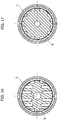
- the female connector 3 is coupled in rotation with the hollow body 1 in the direction indicated by the arrow G in Figure 7 , corresponding to the screwing of this female connector 3 with a complementary male connector, maintaining the hollow body 1 stationary, while it is normally freely rotatable in the opposite direction, i.e. the unscrewing direction.
- the hollow body 1 is formed with a further series of elastically yielding ratchet teeth 17, analogous to the yielding teeth 12, cooperating by unidirectional coupling with corresponding projecting teeth 18 formed on the outside of an initial portion of the appendage 8.
- the hollow body 1 can be formed with a further pair of elastically yielding locking segments 19, analogous to the yielding locking segments 14, the free ends 20 of which are suitable for engaging respective peripheral teeth formations 21 of the appendage 8 ( Figure 6 ).
- the fitting according to the invention advantageously operates in the manner of an intermediate safety element for the coupling of the female connector with the male connector of a medical fluid line, which as already mentioned are connected, instead of directly to each other, to the male connector 2 and the female connector 3, respectively.
- an accidental opening or due to incorrect operation of the medical line is thus reliably prevented, as the separation between the female connector of the line and the male connector 2 cannot be operated, or if at all, can only be operated voluntarily by applying a manual pressure on the elastically yielding segments 14, if present, and similarly, the separation between the male connector of the line and the female connector 3 can possibly be achieved only by pressing the elastically yielding segments 19, if present.
- the fitting indicated as a whole with II, tubular in this case as well, to define an open flow line, essentially differs from the fitting I of Figures 1-7 only in the fact that the outer body 1 is devoid of yielding locking segments 14 and/or 19. Therefore, the fitting II does not allow the voluntary unscrewing of the male connector 2 and/or the female connector 3 from the relative complementary female and male connectors.
- the fitting is analogous to the fitting II and only differs from it in the fact that it is not tubular, or rather it does not define an open flow passage between the two connectors 2 and 3.
- the communication between the two connectors is permanently obstructed: to this effect, the female connector 3 has a transverse obstructive partition 20 ( Figure 21 ).
- connection I is analogous to the connection I and only differs from it in the fact that it also does not define an open flow passage between the two connectors 2 and 3, whose communication is thus obstructed.
- the inner element 4 of the male connector 2 is closed by a transverse partition 21 ( Figure 21 ).
- the fitting is tubular and the male 2 and female 3 connectors are valve connectors of the cleanable (“swabbable”) type.
- the male valve connector 2 generally corresponds to that described in the document US-2012/0271246 by the same Applicant: briefly, it comprises a tubular member 22 having an inlet 23 protruding from one end of the hollow body 1, an elastic hollow element 24 which surrounds the tubular member 22 and has an end wall 25 which normally closes the inlet 23 and is formed with a pre-cut 26.
- a collar 27 surrounds part of the elastic hollow element 24 and is axially movable due to the effect of the coupling of the valve connector 2 with a complementary female connector, inducing a tensile strain of the elastic hollow element 24 and opening the pre-cut 26 and therefore the flow passage through the tubular member 22.
- the female connector valve 3 generally corresponds to that described in the document US-2009/0292274 by the same Applicant: briefly, it comprises an inner hollow pin 28 arranged axially within an intermediate sealing member 29, which is formed with an elastic head 30 having a pre-cut 31, with an elastic hollow element 32 in sealing contact with the hollow pin 28, and with an elastic thrust part 33 tending to maintain the elastic head 30 in a closed condition of the pre-cut 31.
- the elastic head 30 is deformed so as to open the pre-cut 31, and therefore the flow passage through the hollow pin 28.
- the flow passage through the fitting V is normally closed, and only opens following the opening of one and/or the other of the valve connectors 2 and 3.
- the male valve fitting 2 and the female valve fitting 23 are each coupled in rotation with the casing 1 only in the screwing direction, through the respective unidirectional ratchets 12, 13 and 17, 18, and are freely rotatable in the opposite unscrewing direction. They may also possibly be rendered voluntarily integral in rotation with the body 1 in the unscrewing direction as well, acting on the elastically yielding segments 14, 19 of the body 1, if present, similarly to the other embodiments described above.
- valve connectors 2, 3 could be replaced by a non-valvular fitting.
Description
- The present invention relates, in general, to medical fluid lines, for example, hemodialysis lines, chemotherapy lines and the like.
- Such fluid lines are normally fitted along their path with connectors for the connection between the various components of the line: typically male and female luer lock connectors and the like. Accidental disengagement or due to incorrect maneuvers between these connectors can result in possible serious consequences for the patients connected during the use of the line. Documents
EP-A-1747797 (such asEP-A-1747796 ) andUS-A-2013/0187381 disclose tubular fittings for medical fluid lines comprising a hollow body containing a female connector and a male connector, respectively designed to be blocked relative to the body in an unscrewing direction through an axial translation of the with respect to the body. - The object of the present invention is to provide a safe and effective solution to this problem, whilst at the same time being practical and functional.
- According to the invention, this object is achieved thanks to a fitting for medical fluid lines comprising a hollow body within which a male connector accessible at one end of the body and a female connector accessible at the other end of the body, are coaxially housed. The fitting comprises first unidirectional coupling means for locking in rotation the male connector with respect to the body in the direction corresponding to the screwing between said male connector and a complementary female connector of the line, and to enable free rotation of the male connector in the opposite direction, and second unidirectional coupling means for locking in rotation the female connector with respect to the body in the direction corresponding to the screwing between said female connector and a complementary male connector of the line, and to enable free rotation of the female connector in the opposite direction.
- Thanks to this solution idea, the fitting according to the invention is advantageously usable in the form of an intermediate element for a secure connection between a male connector and a female connector of medical fluid lines. In practice, these connectors, instead of being connected directly to each other, are thus connected indirectly, by means of the fitting according to the invention, which ensures the necessary degree of safety against risks of undesired openings of the medical line due to accidental decoupling or a wrong maneuver between the connectors of the line.
- According to the invention, first and/or second locking means are also provided, designed to be positively operated to lock in rotation the male connector and/or the female connector, respectively, with respect to the body in the aforesaid opposite direction of rotation.
- In the fitting according to the invention, the male and female connectors can be in communication with each another to define a flow passage through the fitting, or the communication between the male and female connectors can be obstructed.
- Furthermore, according to a particularly advantageous embodiment of the invention, the female connector can be a valve connector and the male connector can also be a valve connector.
- The invention will now be described in detail with reference to the accompanying drawings, provided purely by way of non-limiting example, in which:
-
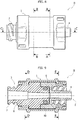
Figure 1 is a schematic perspective view of a fitting for medical fluid lines according to a first embodiment of the invention, -
Figure 2 is an elevational side view of the fitting, -
Figure 3 is an axial section view along the line III-III ofFigure 2 , -
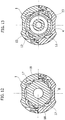
Figure 4 is a cross sectional view along the line IV-IV ofFigure 2 , -
Figure 5 is a cross sectional view along the line V-V ofFigure 3 , -
Figure 6 is a cross sectional view along the line VI-VI ofFigure 2 , -
Figure 7 is a cross sectional view along the line VII-VII ofFigure 3 , -
Figure 8 is an elevational side view of another fitting not according to the invention, -
Figure 9 is an axial section view according to the line C-C ofFigure 8 , -
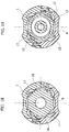
Figure 10 is a cross sectional view along line B-B ofFigure 8 , -
Figure 11 is a cross sectional view along line A-A ofFigure 8 , -
Figure 12 is a cross sectional view along line D-D ofFigure 9 , -
Figure 13 is a cross sectional view along line E-E ofFigure 9 , -
Figure 14 is an elevational side view of another fitting not according to the invention, -
Figure 15 is an axial section view according to the line C-C ofFigure 14 , -
Figure 16 is a cross sectional view along line B-B ofFigure 14 , -
Figure 17 is a cross sectional view along line A-A ofFigure 14 , -
Figure 18 is a cross sectional view along line D-D ofFigure 15 , -
Figure 19 is a cross sectional view along line E-E ofFigure 15 , -
Figure 20 is an elevational side view of an embodiment of the fitting according to the invention, -
Figure 21 is an axial section view according to the line C-C ofFigure 20 , -
Figure 22 is a cross sectional view along line B-B ofFigure 20 , -
Figure 23 is a cross sectional view along line A-A ofFigure 20 , -
Figure 24 is a cross sectional view along line D-D ofFigure 21 , -
Figure 25 is a cross sectional view along line E-E ofFigure 21 , -
Figure 26 is a schematic perspective view of an embodiment of the fitting according to the invention, -
Figure 27 is an end view of the fitting ofFigure 26 , -
Figure 28 is a sectional view along the line A-A ofFigure 27 , and -
Figure 29 is a sectional view along the line B-B ofFigure 28 . - Referring initially to
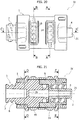
Figures 1 to 7 , the fitting according to a first embodiment of the invention is indicated with I and is tubular. It comprises an outerhollow body 1 of generally cylindrical shape, within which amale connector 2 of the luer lock type and analogues, and afemale fitting 3 of the luer lock type and analogues are coaxially housed in an opposite condition. - The
connectors body 1 and to each another, with the limitations which will be discussed, and have a generally conventional shape. In detail, themale connector 2 comprises an innertubular element 4 with a conical outer surface protruding from one end of thebody 1, and an internally threaded outerhollow element 5, which extends towards the inside of thebody 1 with ahollow appendage 6. - The
female connector 3 consists of an externally threadedtubular element 7 with a conical inner surface, protruding from the other end of thebody 1 and integrally formed with anappendage 8 terminating with ashank 9 rotatably inserted within thehollow appendage 6 of themale connector 2. - The
connectors body 1, which is conveniently formed from two half-shells coupled together in an interlocking manner, and an O-ring seal 10 is interposed between theshank 9 and thehollow appendage 6. - The male and
female connectors - The
hollow appendage 6 of themale connector 2 and theappendage 8 of thefemale connector 3 are locked axially within thehollow body 1 and are coupled with this in rotation in one direction and normally freely rotatable in the opposite direction. However, as will become evident, the rotation in the opposite direction may also possibly be locked, but only following a positive command imparted manually. - In detail, and referring now to
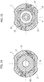
Figures 4 and 5 , thehollow body 1 is formed internally, on the side of themale connector 2, of a crown of elastically yieldingratchet teeth 12 cooperating by unidirectional coupling with corresponding projectingteeth 13 formed on the outside of thehollow element 5 of themale connector 2. The arrangement is such so that thehollow element 5, and therefore the entiremale connector 2, is coupled in rotation with thehollow body 1 in the direction indicated by the arrow F inFigure 5 , due to the effect of the engagement between theteeth male connector 2 and a complementary female connector, assuming thehollow body 1 is kept stationary, and then the complementary female connector is rotated to screw it into themale connector 2. In the opposite direction of rotation, or rather, the unscrewing direction, themale connector 2 is freely rotatable relative to thehollow body 1 due to the bounce of theyielding teeth 12 on theteeth 13, so that the complementary female connector cannot unscrew itself. - Obviously, in the case in which the
hollow body 1 rotates and the complementary female connector is kept stationary, the situation is reversed, i.e. the direction of screwing is opposite to that of the arrow F, and the unscrewing direction is that of the arrow F. - In this way, during use, an accidental disengagement or wrong maneuver between the
male connector 2 and the complementary female connector is prevented. The unscrewing may, however, possibly be allowed, but, as mentioned, only a result of a positive maneuver. To this effect, the wall of thehollow body 1 may also be formed with a pair of elastically yieldinglocking segments 14 whosefree ends 15 are suitable for engaging, as a result of a thrust applied to thesegments 14, respectiveperipheral teeth formations 16 of the hollow appendage 6 (Figure 4 ), so as to lock the rotation of themale connector 2 with respect to thebody 1. - Similarly, and with reference to
Figures 6 and7 , thefemale connector 3 is coupled in rotation with thehollow body 1 in the direction indicated by the arrow G inFigure 7 , corresponding to the screwing of thisfemale connector 3 with a complementary male connector, maintaining thehollow body 1 stationary, while it is normally freely rotatable in the opposite direction, i.e. the unscrewing direction. To this effect, thehollow body 1 is formed with a further series of elastically yielding ratchetteeth 17, analogous to the yieldingteeth 12, cooperating by unidirectional coupling with corresponding projectingteeth 18 formed on the outside of an initial portion of theappendage 8. For possible locking of thefemale connector 3 in rotation with respect to thehollow body 1, in the direction opposite to that indicated by the arrow G, a positive command manual should also be imparted in this case, and to this effect, thehollow body 1 can be formed with a further pair of elastically yielding lockingsegments 19, analogous to the yielding lockingsegments 14, the free ends 20 of which are suitable for engaging respectiveperipheral teeth formations 21 of the appendage 8 (Figure 6 ). - During use, the fitting according to the invention advantageously operates in the manner of an intermediate safety element for the coupling of the female connector with the male connector of a medical fluid line, which as already mentioned are connected, instead of directly to each other, to the
male connector 2 and thefemale connector 3, respectively. Following this connection, an accidental opening or due to incorrect operation of the medical line is thus reliably prevented, as the separation between the female connector of the line and themale connector 2 cannot be operated, or if at all, can only be operated voluntarily by applying a manual pressure on the elastically yieldingsegments 14, if present, and similarly, the separation between the male connector of the line and thefemale connector 3 can possibly be achieved only by pressing the elastically yieldingsegments 19, if present. - The further embodiments of the fitting according to the invention differ from the one already described only in the differences that will now be described in detail, using the same numerical references (partly omitted for simplicity of illustration) for the identical or similar parts.
- In the variant shown in
Figures 8-13 , the fitting, indicated as a whole with II, tubular in this case as well, to define an open flow line, essentially differs from the fitting I ofFigures 1-7 only in the fact that theouter body 1 is devoid of yielding lockingsegments 14 and/or 19. Therefore, the fitting II does not allow the voluntary unscrewing of themale connector 2 and/or thefemale connector 3 from the relative complementary female and male connectors. - In the variant shown in
Figures 14-19 , the fitting, indicated as a whole with III, is analogous to the fitting II and only differs from it in the fact that it is not tubular, or rather it does not define an open flow passage between the twoconnectors female connector 3 has a transverse obstructive partition 20 (Figure 21 ). - In the variant shown in
Figures 20-25 , the fitting, indicated as a whole with IV, is analogous to the connection I and only differs from it in the fact that it also does not define an open flow passage between the twoconnectors inner element 4 of themale connector 2 is closed by a transverse partition 21 (Figure 21 ). - In the variant shown in
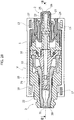
Figures 26-29 , the fitting, indicated as a whole with V, is tubular and themale 2 and female 3 connectors are valve connectors of the cleanable ("swabbable") type. - In particular, the
male valve connector 2 generally corresponds to that described in the documentUS-2012/0271246 by the same Applicant: briefly, it comprises atubular member 22 having aninlet 23 protruding from one end of thehollow body 1, an elastichollow element 24 which surrounds thetubular member 22 and has anend wall 25 which normally closes theinlet 23 and is formed with a pre-cut 26. Acollar 27 surrounds part of the elastichollow element 24 and is axially movable due to the effect of the coupling of thevalve connector 2 with a complementary female connector, inducing a tensile strain of the elastichollow element 24 and opening the pre-cut 26 and therefore the flow passage through thetubular member 22. - The
female connector valve 3 generally corresponds to that described in the documentUS-2009/0292274 by the same Applicant: briefly, it comprises an innerhollow pin 28 arranged axially within anintermediate sealing member 29, which is formed with anelastic head 30 having a pre-cut 31, with an elastichollow element 32 in sealing contact with thehollow pin 28, and with anelastic thrust part 33 tending to maintain theelastic head 30 in a closed condition of the pre-cut 31. When thefemale connector 3 is coupled with a complementary male connector, theelastic head 30 is deformed so as to open the pre-cut 31, and therefore the flow passage through thehollow pin 28. - With this arrangement, the flow passage through the fitting V is normally closed, and only opens following the opening of one and/or the other of the
valve connectors - In this embodiment as well, the male valve fitting 2 and the female valve fitting 23 are each coupled in rotation with the
casing 1 only in the screwing direction, through the respectiveunidirectional ratchets body 1 in the unscrewing direction as well, acting on the elastically yieldingsegments body 1, if present, similarly to the other embodiments described above. - Of course, the details of construction and the embodiments may be varied widely with respect to those described and illustrated. For example, in the case of the fitting V, one or the other of the
valve connectors
Claims (9)
- A tubular fitting (I, IV, V) for medical fluid lines, comprising a hollow body (1) within which a male connector (2) accessible at one end of the body (1) and a female connector (3) accessible at the other end of the body (1), are coaxially housed, characterized in that it comprises first unidirectional coupling means comprising ratchet teeth (12) cooperating with corresponding projecting teeth (13) to lock in rotation the male connector (2) with respect to the body (1) in the direction (F) corresponding to the screwing of said male connector (2) and a complementary female connector to be coupled therewith, and to enable free rotation of the male connector (2) in the opposite direction, and second unidirectional coupling means comprising ratchet teeth (17) cooperating with corresponding projecting teeth (18) being provided to lock in rotation the female connector (3) with respect to the body (1) in a direction corresponding to the screwing of said female connector (3) and a complementary male connector to be coupled therewith, and to enable free rotation of the female connector (3) in the opposite direction,
wherein first locking means (14, 16) are provided and designed to be positively operated to lock in rotation one of said male connector (2) and female connector (3), relative to the body (1) in said opposite direction,
wherein second locking means (19, 21) are provided and designed to be positively operated to lock in rotation the other of said female connector (3) and male connector (2), relative to the body (1) in said opposite direction,
wherein said first and second locking means comprise respective elastically yielding segments (14, 19) of the body (1), designed to engage corresponding peripheral teeth (16, 21) of said male connector (2) and female connector (3), respectively. - A fitting according to claim 1, characterized in that said male and female connectors (2, 3) are coupled together in a mutually rotary fashion with the interposition of an O-ring (10).
- A fitting according to claim 1, characterized in that said male and female connectors (2, 3) are in communication with each another to define an open flow passage through the fitting (I, V).
- A fitting according to claim 1, characterized in that the communication between said male and female connectors (2, 3) is obstructed.
- A fitting according to claim 4, characterized in that at least one of said male and female connectors (2, 3) has a transverse partition (20; 21) for closing the flow through said fitting (IV).
- A fitting according to one or more of the preceding claims, characterized in that the male connector (2) is a valve connector.
- A fitting according to claim 6, characterized in that the male connector (2) comprises a tubular member (22) having an inlet (23), an elastic hollow element (24) that surrounds said tubular member (22) and has an end wall (25) that closes said inlet (23) of the tubular member (22) and is formed with a pre-cut (26), and a collar (27) axially displaceable to cause a tensile strain of the elastic hollow element elastic (24) so as to open said pre-cut (26).
- A fitting according to one or more of the preceding claims, characterized in that the female connector (3) is a valve connector.
- A fitting according to claim 8, characterized in that the female connector (3) comprises an inner hollow pin (28) arranged axially within an intermediate sealing member (29) having an elastic head (30) formed with a pre-cut (31), an elastic hollow element (32) in sealing contact with the hollow pin (28) and an elastic thrust part (33) tending to maintain the elastic head (30) in a closed condition of said pre-cut (31).
Priority Applications (3)
| Application Number | Priority Date | Filing Date | Title |
|---|---|---|---|
| RS20190480A RS58631B1 (en) | 2014-05-12 | 2014-07-21 | Tubular fitting for medical fluid lines |
| PL14777784T PL3142741T3 (en) | 2014-05-12 | 2014-07-21 | Tubular fitting for medical fluid lines |
| HRP20190760TT HRP20190760T1 (en) | 2014-05-12 | 2019-04-24 | Tubular fitting for medical fluid lines |
Applications Claiming Priority (2)
| Application Number | Priority Date | Filing Date | Title |
|---|---|---|---|
| ITTO20140371 | 2014-05-12 | ||
| PCT/IB2014/063278 WO2015173612A1 (en) | 2014-05-12 | 2014-07-21 | Tubular fitting for medical fluid lines |
Publications (2)
| Publication Number | Publication Date |
|---|---|
| EP3142741A1 EP3142741A1 (en) | 2017-03-22 |
| EP3142741B1 true EP3142741B1 (en) | 2019-03-27 |
Family
ID=51179061
Family Applications (1)
| Application Number | Title | Priority Date | Filing Date |
|---|---|---|---|
| EP14777784.1A Active EP3142741B1 (en) | 2014-05-12 | 2014-07-21 | Tubular fitting for medical fluid lines |
Country Status (18)
| Country | Link |
|---|---|
| US (2) | US10155103B2 (en) |
| EP (1) | EP3142741B1 (en) |
| JP (1) | JP6463782B2 (en) |
| KR (1) | KR102256852B1 (en) |
| CN (1) | CN106456959B (en) |
| AU (1) | AU2014394386B2 (en) |
| CA (1) | CA2947389C (en) |
| DK (1) | DK3142741T3 (en) |
| ES (1) | ES2719956T3 (en) |
| HR (1) | HRP20190760T1 (en) |
| MX (1) | MX2016014471A (en) |
| NZ (1) | NZ726039A (en) |
| PL (1) | PL3142741T3 (en) |
| PT (1) | PT3142741T (en) |
| RS (1) | RS58631B1 (en) |
| SG (1) | SG11201608968YA (en) |
| TR (1) | TR201905550T4 (en) |
| WO (1) | WO2015173612A1 (en) |
Families Citing this family (4)
| Publication number | Priority date | Publication date | Assignee | Title |
|---|---|---|---|---|
| US10022531B2 (en) | 2016-01-21 | 2018-07-17 | Teva Medical Ltd. | Luer lock adaptor |
| IT201600075597A1 (en) * | 2016-07-19 | 2018-01-19 | Borla Ind | FLOW COMPONENT PARTICULARLY FOR MEDICAL LINES FOR HEMODIALYSIS |
| CN112867530A (en) * | 2018-10-19 | 2021-05-28 | 费森尤斯卡比德国有限公司 | Connector assembly for connecting medical lines |
| WO2023156975A1 (en) * | 2022-02-18 | 2023-08-24 | West Pharma. Services IL, Ltd. | Closed-liquid transfer devices and systems |
Family Cites Families (11)
| Publication number | Priority date | Publication date | Assignee | Title |
|---|---|---|---|---|
| DE4318101A1 (en) | 1993-06-01 | 1994-12-08 | Sterimed Gmbh | Hose coupling |
| US5620427A (en) * | 1995-04-27 | 1997-04-15 | David R. Kipp | Luer lock system |
| GB2410305B (en) * | 2001-09-04 | 2005-12-07 | Clinical Product Dev Ltd | Couplings for medical fluid delivery systems |
| US7497484B2 (en) * | 2004-08-11 | 2009-03-03 | Smiths Medical Asd, Inc. | Medical coupling system |
| ITTO20050516A1 (en) * | 2005-07-25 | 2007-01-26 | Borla Ind | MEDICAL CONNECTOR |
| ITTO20050515A1 (en) * | 2005-07-25 | 2007-01-26 | Borla Ind | MEDICAL VALVE CONNECTOR |
| ITTO20080381A1 (en) * | 2008-05-21 | 2009-11-22 | Industrie Borla Spa | VALVE VALVE FOR MEDICAL LINES |
| IT1396791B1 (en) | 2009-11-26 | 2012-12-14 | Borla Ind | VALVE MALE LUER CONNECTOR |
| CN102971039B (en) | 2010-05-21 | 2015-07-15 | 卡麦尔药物股份公司 | Connector and fluid container |
| ITTO20120056A1 (en) * | 2012-01-24 | 2013-07-25 | Borla Ind | CONNECTOR FOR MEDICAL LINES OF INFUSION, TRANSFUSION AND THE LIKE |
| ITTO20130433A1 (en) * | 2013-05-29 | 2014-11-30 | Borla Ind | CONNECTOR FOR MEDICAL LINES |
-
2014
- 2014-07-21 TR TR2019/05550T patent/TR201905550T4/en unknown
- 2014-07-21 SG SG11201608968YA patent/SG11201608968YA/en unknown
- 2014-07-21 AU AU2014394386A patent/AU2014394386B2/en active Active
- 2014-07-21 MX MX2016014471A patent/MX2016014471A/en unknown
- 2014-07-21 EP EP14777784.1A patent/EP3142741B1/en active Active
- 2014-07-21 PL PL14777784T patent/PL3142741T3/en unknown
- 2014-07-21 JP JP2016567487A patent/JP6463782B2/en active Active
- 2014-07-21 WO PCT/IB2014/063278 patent/WO2015173612A1/en active Application Filing
- 2014-07-21 DK DK14777784.1T patent/DK3142741T3/en active
- 2014-07-21 US US15/311,056 patent/US10155103B2/en active Active
- 2014-07-21 NZ NZ726039A patent/NZ726039A/en unknown
- 2014-07-21 ES ES14777784T patent/ES2719956T3/en active Active
- 2014-07-21 CN CN201480078826.8A patent/CN106456959B/en active Active
- 2014-07-21 PT PT14777784T patent/PT3142741T/en unknown
- 2014-07-21 CA CA2947389A patent/CA2947389C/en active Active
- 2014-07-21 KR KR1020167034091A patent/KR102256852B1/en active IP Right Grant
- 2014-07-21 RS RS20190480A patent/RS58631B1/en unknown
-
2018
- 2018-11-08 US US16/184,539 patent/US10537726B2/en active Active
-
2019
- 2019-04-24 HR HRP20190760TT patent/HRP20190760T1/en unknown
Non-Patent Citations (1)
| Title |
|---|
| None * |
Also Published As
| Publication number | Publication date |
|---|---|
| PL3142741T3 (en) | 2019-08-30 |
| RS58631B1 (en) | 2019-05-31 |
| KR102256852B1 (en) | 2021-05-27 |
| JP2017515578A (en) | 2017-06-15 |
| ES2719956T3 (en) | 2019-07-17 |
| SG11201608968YA (en) | 2016-11-29 |
| EP3142741A1 (en) | 2017-03-22 |
| CN106456959A (en) | 2017-02-22 |
| US10537726B2 (en) | 2020-01-21 |
| US20190076641A1 (en) | 2019-03-14 |
| US20170120031A1 (en) | 2017-05-04 |
| NZ726039A (en) | 2020-01-31 |
| AU2014394386A1 (en) | 2016-11-24 |
| DK3142741T3 (en) | 2019-06-11 |
| JP6463782B2 (en) | 2019-02-06 |
| KR20170002564A (en) | 2017-01-06 |
| TR201905550T4 (en) | 2019-05-21 |
| MX2016014471A (en) | 2017-02-23 |
| US10155103B2 (en) | 2018-12-18 |
| CA2947389C (en) | 2021-01-12 |
| CA2947389A1 (en) | 2015-11-19 |
| PT3142741T (en) | 2019-05-21 |
| HRP20190760T1 (en) | 2019-06-28 |
| WO2015173612A1 (en) | 2015-11-19 |
| CN106456959B (en) | 2020-03-17 |
| AU2014394386B2 (en) | 2019-09-12 |
Similar Documents
| Publication | Publication Date | Title |
|---|---|---|
| US10537726B2 (en) | Tubular fitting for medical fluid lines | |
| EP2237830B1 (en) | Valve connector for medical lines | |
| US9360142B2 (en) | Female quick coupling element and quick coupling including such an element | |
| CA2801798C (en) | Connector for medical lines | |
| EP3004711B1 (en) | Connector for medical lines | |
| EP3171926B1 (en) | Safety connector for medical devices | |
| EP3047872A1 (en) | Valved male luer connector | |
| WO2016193693A8 (en) | Medical connector with two valves | |
| BR112016026222B1 (en) | TUBULAR ACCESSORY FOR MEDICAL FLUID LINES | |
| BR112016030802B1 (en) | COVER FOR MEDICAL AND SIMILAR FLUID LINES |
Legal Events
| Date | Code | Title | Description |
|---|---|---|---|
| STAA | Information on the status of an ep patent application or granted ep patent |
Free format text: STATUS: THE INTERNATIONAL PUBLICATION HAS BEEN MADE |
|
| PUAI | Public reference made under article 153(3) epc to a published international application that has entered the european phase |
Free format text: ORIGINAL CODE: 0009012 |
|
| STAA | Information on the status of an ep patent application or granted ep patent |
Free format text: STATUS: REQUEST FOR EXAMINATION WAS MADE |
|
| 17P | Request for examination filed |
Effective date: 20161027 |
|
| AK | Designated contracting states |
Kind code of ref document: A1 Designated state(s): AL AT BE BG CH CY CZ DE DK EE ES FI FR GB GR HR HU IE IS IT LI LT LU LV MC MK MT NL NO PL PT RO RS SE SI SK SM TR |
|
| AX | Request for extension of the european patent |
Extension state: BA ME |
|
| RAX | Requested extension states of the european patent have changed |
Extension state: BA Payment date: 20161027 |
|
| GRAP | Despatch of communication of intention to grant a patent |
Free format text: ORIGINAL CODE: EPIDOSNIGR1 |
|
| STAA | Information on the status of an ep patent application or granted ep patent |
Free format text: STATUS: GRANT OF PATENT IS INTENDED |
|
| INTG | Intention to grant announced |
Effective date: 20181217 |
|
| GRAS | Grant fee paid |
Free format text: ORIGINAL CODE: EPIDOSNIGR3 |
|
| GRAA | (expected) grant |
Free format text: ORIGINAL CODE: 0009210 |
|
| STAA | Information on the status of an ep patent application or granted ep patent |
Free format text: STATUS: THE PATENT HAS BEEN GRANTED |
|
| AK | Designated contracting states |
Kind code of ref document: B1 Designated state(s): AL AT BE BG CH CY CZ DE DK EE ES FI FR GB GR HR HU IE IS IT LI LT LU LV MC MK MT NL NO PL PT RO RS SE SI SK SM TR |
|
| AX | Request for extension of the european patent |
Extension state: BA |
|
| REG | Reference to a national code |
Ref country code: GB Ref legal event code: FG4D |
|
| REG | Reference to a national code |
Ref country code: CH Ref legal event code: EP |
|
| REG | Reference to a national code |
Ref country code: AT Ref legal event code: REF Ref document number: 1112306 Country of ref document: AT Kind code of ref document: T Effective date: 20190415 |
|
| REG | Reference to a national code |
Ref country code: IE Ref legal event code: FG4D |
|
| REG | Reference to a national code |
Ref country code: DE Ref legal event code: R096 Ref document number: 602014043691 Country of ref document: DE |
|
| REG | Reference to a national code |
Ref country code: HR Ref legal event code: TUEP Ref document number: P20190760 Country of ref document: HR |
|
| REG | Reference to a national code |
Ref country code: PT Ref legal event code: SC4A Ref document number: 3142741 Country of ref document: PT Date of ref document: 20190521 Kind code of ref document: T Free format text: AVAILABILITY OF NATIONAL TRANSLATION Effective date: 20190422 |
|
| REG | Reference to a national code |
Ref country code: DK Ref legal event code: T3 Effective date: 20190604 |
|
| REG | Reference to a national code |
Ref country code: NL Ref legal event code: FP |
|
| REG | Reference to a national code |
Ref country code: RO Ref legal event code: EPE |
|
| REG | Reference to a national code |
Ref country code: HR Ref legal event code: T1PR Ref document number: P20190760 Country of ref document: HR |
|
| REG | Reference to a national code |
Ref country code: SE Ref legal event code: TRGR |
|
| REG | Reference to a national code |
Ref country code: ES Ref legal event code: FG2A Ref document number: 2719956 Country of ref document: ES Kind code of ref document: T3 Effective date: 20190717 |
|
| REG | Reference to a national code |
Ref country code: HR Ref legal event code: ODRP Ref document number: P20190760 Country of ref document: HR Payment date: 20190710 Year of fee payment: 6 |
|
| PG25 | Lapsed in a contracting state [announced via postgrant information from national office to epo] |
Ref country code: LT Free format text: LAPSE BECAUSE OF FAILURE TO SUBMIT A TRANSLATION OF THE DESCRIPTION OR TO PAY THE FEE WITHIN THE PRESCRIBED TIME-LIMIT Effective date: 20190327 Ref country code: FI Free format text: LAPSE BECAUSE OF FAILURE TO SUBMIT A TRANSLATION OF THE DESCRIPTION OR TO PAY THE FEE WITHIN THE PRESCRIBED TIME-LIMIT Effective date: 20190327 Ref country code: NO Free format text: LAPSE BECAUSE OF FAILURE TO SUBMIT A TRANSLATION OF THE DESCRIPTION OR TO PAY THE FEE WITHIN THE PRESCRIBED TIME-LIMIT Effective date: 20190627 |
|
| PG25 | Lapsed in a contracting state [announced via postgrant information from national office to epo] |
Ref country code: LV Free format text: LAPSE BECAUSE OF FAILURE TO SUBMIT A TRANSLATION OF THE DESCRIPTION OR TO PAY THE FEE WITHIN THE PRESCRIBED TIME-LIMIT Effective date: 20190327 Ref country code: BG Free format text: LAPSE BECAUSE OF FAILURE TO SUBMIT A TRANSLATION OF THE DESCRIPTION OR TO PAY THE FEE WITHIN THE PRESCRIBED TIME-LIMIT Effective date: 20190627 |
|
| REG | Reference to a national code |
Ref country code: AT Ref legal event code: MK05 Ref document number: 1112306 Country of ref document: AT Kind code of ref document: T Effective date: 20190327 |
|
| REG | Reference to a national code |
Ref country code: GR Ref legal event code: EP Ref document number: 20190401846 Country of ref document: GR Effective date: 20190906 |
|
| PG25 | Lapsed in a contracting state [announced via postgrant information from national office to epo] |
Ref country code: AL Free format text: LAPSE BECAUSE OF FAILURE TO SUBMIT A TRANSLATION OF THE DESCRIPTION OR TO PAY THE FEE WITHIN THE PRESCRIBED TIME-LIMIT Effective date: 20190327 Ref country code: SK Free format text: LAPSE BECAUSE OF FAILURE TO SUBMIT A TRANSLATION OF THE DESCRIPTION OR TO PAY THE FEE WITHIN THE PRESCRIBED TIME-LIMIT Effective date: 20190327 Ref country code: EE Free format text: LAPSE BECAUSE OF FAILURE TO SUBMIT A TRANSLATION OF THE DESCRIPTION OR TO PAY THE FEE WITHIN THE PRESCRIBED TIME-LIMIT Effective date: 20190327 |
|
| PG25 | Lapsed in a contracting state [announced via postgrant information from national office to epo] |
Ref country code: SM Free format text: LAPSE BECAUSE OF FAILURE TO SUBMIT A TRANSLATION OF THE DESCRIPTION OR TO PAY THE FEE WITHIN THE PRESCRIBED TIME-LIMIT Effective date: 20190327 |
|
| PG25 | Lapsed in a contracting state [announced via postgrant information from national office to epo] |
Ref country code: IS Free format text: LAPSE BECAUSE OF FAILURE TO SUBMIT A TRANSLATION OF THE DESCRIPTION OR TO PAY THE FEE WITHIN THE PRESCRIBED TIME-LIMIT Effective date: 20190727 Ref country code: AT Free format text: LAPSE BECAUSE OF FAILURE TO SUBMIT A TRANSLATION OF THE DESCRIPTION OR TO PAY THE FEE WITHIN THE PRESCRIBED TIME-LIMIT Effective date: 20190327 |
|
| REG | Reference to a national code |
Ref country code: DE Ref legal event code: R097 Ref document number: 602014043691 Country of ref document: DE |
|
| PLBE | No opposition filed within time limit |
Free format text: ORIGINAL CODE: 0009261 |
|
| STAA | Information on the status of an ep patent application or granted ep patent |
Free format text: STATUS: NO OPPOSITION FILED WITHIN TIME LIMIT |
|
| PG25 | Lapsed in a contracting state [announced via postgrant information from national office to epo] |
Ref country code: SI Free format text: LAPSE BECAUSE OF FAILURE TO SUBMIT A TRANSLATION OF THE DESCRIPTION OR TO PAY THE FEE WITHIN THE PRESCRIBED TIME-LIMIT Effective date: 20190327 |
|
| REG | Reference to a national code |
Ref country code: CH Ref legal event code: PL |
|
| 26N | No opposition filed |
Effective date: 20200103 |
|
| PG25 | Lapsed in a contracting state [announced via postgrant information from national office to epo] |
Ref country code: LU Free format text: LAPSE BECAUSE OF NON-PAYMENT OF DUE FEES Effective date: 20190721 Ref country code: LI Free format text: LAPSE BECAUSE OF NON-PAYMENT OF DUE FEES Effective date: 20190731 Ref country code: CH Free format text: LAPSE BECAUSE OF NON-PAYMENT OF DUE FEES Effective date: 20190731 |
|
| REG | Reference to a national code |
Ref country code: HR Ref legal event code: ODRP Ref document number: P20190760 Country of ref document: HR Payment date: 20200707 Year of fee payment: 7 |
|
| PG25 | Lapsed in a contracting state [announced via postgrant information from national office to epo] |
Ref country code: CY Free format text: LAPSE BECAUSE OF FAILURE TO SUBMIT A TRANSLATION OF THE DESCRIPTION OR TO PAY THE FEE WITHIN THE PRESCRIBED TIME-LIMIT Effective date: 20190327 |
|
| PG25 | Lapsed in a contracting state [announced via postgrant information from national office to epo] |
Ref country code: MT Free format text: LAPSE BECAUSE OF FAILURE TO SUBMIT A TRANSLATION OF THE DESCRIPTION OR TO PAY THE FEE WITHIN THE PRESCRIBED TIME-LIMIT Effective date: 20190327 Ref country code: HU Free format text: LAPSE BECAUSE OF FAILURE TO SUBMIT A TRANSLATION OF THE DESCRIPTION OR TO PAY THE FEE WITHIN THE PRESCRIBED TIME-LIMIT; INVALID AB INITIO Effective date: 20140721 |
|
| REG | Reference to a national code |
Ref country code: HR Ref legal event code: ODRP Ref document number: P20190760 Country of ref document: HR Payment date: 20210705 Year of fee payment: 8 |
|
| PG25 | Lapsed in a contracting state [announced via postgrant information from national office to epo] |
Ref country code: MK Free format text: LAPSE BECAUSE OF FAILURE TO SUBMIT A TRANSLATION OF THE DESCRIPTION OR TO PAY THE FEE WITHIN THE PRESCRIBED TIME-LIMIT Effective date: 20190327 |
|
| REG | Reference to a national code |
Ref country code: HR Ref legal event code: ODRP Ref document number: P20190760 Country of ref document: HR Payment date: 20220704 Year of fee payment: 9 |
|
| P01 | Opt-out of the competence of the unified patent court (upc) registered |
Effective date: 20230615 |
|
| PGFP | Annual fee paid to national office [announced via postgrant information from national office to epo] |
Ref country code: RS Payment date: 20230630 Year of fee payment: 10 Ref country code: PT Payment date: 20230628 Year of fee payment: 10 Ref country code: DK Payment date: 20230626 Year of fee payment: 10 |
|
| REG | Reference to a national code |
Ref country code: HR Ref legal event code: ODRP Ref document number: P20190760 Country of ref document: HR Payment date: 20230630 Year of fee payment: 10 |
|
| PGFP | Annual fee paid to national office [announced via postgrant information from national office to epo] |
Ref country code: PL Payment date: 20230629 Year of fee payment: 10 Ref country code: NL Payment date: 20230726 Year of fee payment: 10 Ref country code: HR Payment date: 20230630 Year of fee payment: 10 |
|
| PGFP | Annual fee paid to national office [announced via postgrant information from national office to epo] |
Ref country code: TR Payment date: 20230703 Year of fee payment: 10 Ref country code: RO Payment date: 20230705 Year of fee payment: 10 Ref country code: MC Payment date: 20230719 Year of fee payment: 10 Ref country code: IT Payment date: 20230705 Year of fee payment: 10 Ref country code: IE Payment date: 20230718 Year of fee payment: 10 Ref country code: GB Payment date: 20230725 Year of fee payment: 10 Ref country code: ES Payment date: 20230816 Year of fee payment: 10 Ref country code: CZ Payment date: 20230720 Year of fee payment: 10 |
|
| PGFP | Annual fee paid to national office [announced via postgrant information from national office to epo] |
Ref country code: SE Payment date: 20230726 Year of fee payment: 10 Ref country code: GR Payment date: 20230720 Year of fee payment: 10 Ref country code: FR Payment date: 20230725 Year of fee payment: 10 Ref country code: DE Payment date: 20230726 Year of fee payment: 10 Ref country code: BE Payment date: 20230726 Year of fee payment: 10 |