EP3142306B1 - Openflow communication method, system, controller, and service gateway - Google Patents
Openflow communication method, system, controller, and service gateway Download PDFInfo
- Publication number
- EP3142306B1 EP3142306B1 EP14894130.5A EP14894130A EP3142306B1 EP 3142306 B1 EP3142306 B1 EP 3142306B1 EP 14894130 A EP14894130 A EP 14894130A EP 3142306 B1 EP3142306 B1 EP 3142306B1
- Authority
- EP
- European Patent Office
- Prior art keywords
- packet
- virtual switch
- flow table
- action
- service gateway
- Prior art date
- Legal status (The legal status is an assumption and is not a legal conclusion. Google has not performed a legal analysis and makes no representation as to the accuracy of the status listed.)
- Active
Links
Images


Classifications
-
- H—ELECTRICITY
- H04—ELECTRIC COMMUNICATION TECHNIQUE
- H04L—TRANSMISSION OF DIGITAL INFORMATION, e.g. TELEGRAPHIC COMMUNICATION
- H04L45/00—Routing or path finding of packets in data switching networks
- H04L45/64—Routing or path finding of packets in data switching networks using an overlay routing layer
-
- H—ELECTRICITY
- H04—ELECTRIC COMMUNICATION TECHNIQUE
- H04L—TRANSMISSION OF DIGITAL INFORMATION, e.g. TELEGRAPHIC COMMUNICATION
- H04L45/00—Routing or path finding of packets in data switching networks
- H04L45/74—Address processing for routing
-
- H—ELECTRICITY
- H04—ELECTRIC COMMUNICATION TECHNIQUE
- H04L—TRANSMISSION OF DIGITAL INFORMATION, e.g. TELEGRAPHIC COMMUNICATION
- H04L12/00—Data switching networks
- H04L12/28—Data switching networks characterised by path configuration, e.g. LAN [Local Area Networks] or WAN [Wide Area Networks]
- H04L12/46—Interconnection of networks
- H04L12/4633—Interconnection of networks using encapsulation techniques, e.g. tunneling
-
- H—ELECTRICITY
- H04—ELECTRIC COMMUNICATION TECHNIQUE
- H04L—TRANSMISSION OF DIGITAL INFORMATION, e.g. TELEGRAPHIC COMMUNICATION
- H04L12/00—Data switching networks
- H04L12/66—Arrangements for connecting between networks having differing types of switching systems, e.g. gateways
-
- H—ELECTRICITY
- H04—ELECTRIC COMMUNICATION TECHNIQUE
- H04L—TRANSMISSION OF DIGITAL INFORMATION, e.g. TELEGRAPHIC COMMUNICATION
- H04L45/00—Routing or path finding of packets in data switching networks
- H04L45/02—Topology update or discovery
-
- H—ELECTRICITY
- H04—ELECTRIC COMMUNICATION TECHNIQUE
- H04L—TRANSMISSION OF DIGITAL INFORMATION, e.g. TELEGRAPHIC COMMUNICATION
- H04L45/00—Routing or path finding of packets in data switching networks
- H04L45/74—Address processing for routing
- H04L45/745—Address table lookup; Address filtering
-
- H—ELECTRICITY
- H04—ELECTRIC COMMUNICATION TECHNIQUE
- H04L—TRANSMISSION OF DIGITAL INFORMATION, e.g. TELEGRAPHIC COMMUNICATION
- H04L45/00—Routing or path finding of packets in data switching networks
- H04L45/76—Routing in software-defined topologies, e.g. routing between virtual machines
-
- H—ELECTRICITY
- H04—ELECTRIC COMMUNICATION TECHNIQUE
- H04L—TRANSMISSION OF DIGITAL INFORMATION, e.g. TELEGRAPHIC COMMUNICATION
- H04L47/00—Traffic control in data switching networks
- H04L47/10—Flow control; Congestion control
- H04L47/12—Avoiding congestion; Recovering from congestion
- H04L47/125—Avoiding congestion; Recovering from congestion by balancing the load, e.g. traffic engineering
-
- H—ELECTRICITY
- H04—ELECTRIC COMMUNICATION TECHNIQUE
- H04L—TRANSMISSION OF DIGITAL INFORMATION, e.g. TELEGRAPHIC COMMUNICATION
- H04L49/00—Packet switching elements
- H04L49/30—Peripheral units, e.g. input or output ports
- H04L49/3009—Header conversion, routing tables or routing tags
-
- H—ELECTRICITY
- H04—ELECTRIC COMMUNICATION TECHNIQUE
- H04L—TRANSMISSION OF DIGITAL INFORMATION, e.g. TELEGRAPHIC COMMUNICATION
- H04L49/00—Packet switching elements
- H04L49/70—Virtual switches
Definitions
- the present invention relates to the communications field, and in particular, to an OpenFlow communication method and system, a controller, and a service gateway.
- An enterprise service gateway is an entrance to a data center and cloud service center. A throughput capability of the enterprise service gateway directly affects performance of the entire data center and cloud service center.
- OpenFlow OpenFlow
- the OpenFlow protocol is gradually improved and successfully applied to an actual network, where application of the OpenFlow protocol to a data center network is particularly prominent.
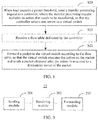
- a topology structure of an OpenFlow network includes: an Openflow controller 11, an Openflow switch 12, a terminal 13, and links connecting the Openflow controller 11, Openflow switch 12, and terminal 13.
- the Openflow controller 11 stores a topology structure of an entire network, generates a flow table for a data flow that needs to be forwarded, and delivers the flow table to a corresponding switch.
- the Openflow switch 12 stores flow table information delivered by the Openflow controller 11 and performs data forwarding between the Openflow switches 12 and between the Openflow switch 12 and the terminal 13.
- a topology structure of the data center network is generally a tree structure.
- the enterprise service gateway as the entrance (a root) to the data center, is responsible for network forwarding and further needs to perform particular processing on data, for example: in terms of network security, to perform "encryption/decryption, DPI (Deep Packet Inspection, deep packet inspection technology), and the like" on the data; and to perform data compression and decompression, and the like.
- the processing includes:
- WO 2006091411 A3 discloses that a method for load balancing communication session processing in a data network platform.
- US2008276093 discloses a system for managing service mobility using an extensible Markup Language (XML) electronic signature.
- US2013311778 discloses a system and method for secure cloud service delivery in a network environment.
- US2005027404 discloses an apparatus for controlling communication between units in a vehicle.
- US2006277303 discloses a method for improving response time for clients requesting network services.
- An enterprise service gateway in the prior art serves as an entrance to an entire data center.
- a to-be-processed data volume exceeds a capability of the enterprise service gateway, the enterprise service gateway becomes a bottleneck of an entire system whereas a large quantity of computing resources on a back-end server are idle. Therefore, a method for resolving the bottleneck problem needs to be found.
- embodiments of the present invention provide an OpenFlow communication method and system, a controller, and a service gateway, which can implement load balance among network elements in a system, improve utilization and a throughput of the system, and further enhance performance of the entire system, as defined by the independent claims. Further embodiments are provided by the dependent claims..
- an OpenFlow communication method includes: when load exceeds a preset threshold, receiving by a controller, a transfer processing request sent by a service gateway, where the transfer processing request includes an action that needs to be transferred; selecting, by the controller, one server as a virtual switch according to the action that needs to be transferred and a network topology structure; delivering, by the controller, a first flow table to the service gateway, where the first flow table is used for the service gateway to forward a packet to the virtual switch; and delivering, by the controller a second flow table to the virtual switch, where the second flow table includes an instruction used to instruct the virtual switch to execute the action on the packet, so that the virtual switch executes the action on the packet and sends a packet obtained after the action is executed to a destination server of the packet.
- the method further includes: if the virtual switch has no flow table for sending the packet to the destination server of the packet, receiving a message that requests a processing rule of the packet and is sent by the virtual switch for the packet; and delivering a third flow table to the virtual switch, where the third flow table is used for the virtual switch to send the packet obtained after the action is executed to the destination server of the packet.
- the action includes at least one of packet encryption, packet decryption, deep packet inspection, data compression, or data decompression.
- a controller including: a receiving module, configured to receive a transfer processing request sent by a service gateway, when load exceeds a preset threshold, where the transfer processing request includes an action that needs to be transferred; a selection module, configured to select one server as a virtual switch according to the action that needs to be transferred and a network topology structure; a first flow table delivering module, configured to deliver a first flow table to the service gateway, where the first flow table is used for the service gateway to forward a packet to the virtual switch; and a second flow table delivering module, configured to deliver a second flow table to the virtual switch, where the second flow table includes an instruction used to instruct the virtual switch to execute the action on the packet, so that the virtual switch executes the action on the packet and sends a packet obtained after the action is executed to a destination server of the packet.
- the controller further includes a third flow table delivering module, where the receiving module receives a message that requests a processing rule of the packet and is sent by the virtual switch for the packet; and the third delivering module delivers a third flow table to the virtual switch, where the third flow table is used for the virtual switch to send the packet obtained after the action is executed to the destination server of the packet.
- the action includes at least one of packet encryption, packet decryption, deep packet inspection, data compression, or data decompression.
- an OpenFlow communication method including: when load exceeds a preset threshold, sending, by a service gateway, a transfer processing request to a controller, where the transfer processing request includes an action that needs to be transferred, so that the controller selects one server as a virtual switch; receiving, by the service gateway a flow table delivered by the controller; and forwarding, by a service gateway, a packet to the virtual switch according to the flow table, so that the virtual switch executes the action on the packet and sends a packet obtained after the action is executed to a destination server of the packet.
- the forwarding a packet to the virtual switch according to the flow table is specifically forwarding the packet encapsulated in an IP_IN_IP manner to the virtual switch according to the flow table.
- the action includes at least one of packet encryption, packet decryption, deep packet inspection, data compression, or data decompression.
- a service gateway including: a sending module, configured to: when load exceeds a preset threshold, send a transfer processing request to a controller, where the transfer processing request includes an action that needs to be transferred, so that the controller selects one server as a virtual switch; a receiving module, configured to receive a flow table delivered by the controller; and a forwarding module, configured to forward a packet to the virtual switch according to the flow table, so that the virtual switch executes the action on the packet and sends a packet obtained after the action is executed to a destination server of the packet.
- the forwarding module is specifically configured to forward the packet encapsulated in an IP_IN_IP manner to the virtual switch according to the flow table.
- the action includes at least one of packet encryption, packet decryption, deep packet inspection, data compression, or data decompression.
- a controller including a receiver, a processor, a transmitter, and a memory, where the receiver is configured to receive a transfer processing request sent by a service gateway when load exceeds a preset threshold, where the transfer processing request includes an action that needs to be transferred; the memory is configured to store program code; the processor is connected to the receiver and configured to invoke the program code stored in the memory to execute the following method: selecting one server as a virtual switch according to the action that needs to be transferred and a network topology structure; the transmitter is further configured to deliver a first flow table to the service gateway, where the first flow table is used for the service gateway to forward a packet to the virtual switch; and the transmitter is further configured to deliver a second flow table to the virtual switch, where the second flow table includes an instruction used to instruct the virtual switch to execute the action on the packet, so that the virtual switch executes the action on the packet and sends a packet obtained after the action is executed to a destination server of the packet.
- the receiver is further configured to receive a message that requests a processing rule of the packet and is sent by the virtual switch for the packet; and the transmitter delivers a third flow table to the virtual switch, where the third flow table is used for the virtual switch to send the packet obtained after the action is executed to the destination server of the packet.
- the action includes at least one of packet encryption, packet decryption, deep packet inspection, data compression, or data decompression.
- a service gateway including a transmitter, receiver, a processor, and a memory, where when load exceeds a preset threshold, the transmitter is configured to send a transfer processing request to a controller, where the transfer processing request includes an action that needs to be transferred, so that the controller selects one server as a virtual switch; the receiver is configured to receive a flow table delivered by the controller; the memory is configured to store program code; and the processor is configured to invoke the program code stored in the memory to execute the following method: forwarding a packet to the virtual switch according to the flow table, so that the virtual switch executes the action on the packet and sends a packet obtained after the action is executed to a destination server of the packet.
- the forwarding a packet to the virtual switch according to the flow table in the method executed by the processor is specifically: forwarding the packet encapsulated in an IP_IN_IP manner to the virtual switch through a first data channel according to the flow table.
- the action includes at least one of packet encryption, packet decryption, deep packet inspection, data compression, or data decompression.
- an OpenFlow communication system including a controller, a service gateway, and at least one server, where the service gateway sends a transfer processing request to the controller when load exceeds a preset threshold, where the transfer processing request includes an action that needs to be transferred; the controller selects one server of the at least one server as a virtual switch according to the action that needs to be transferred and a network topology structure; the controller delivers a first flow table to the service gateway; the service gateway forwards a packet to the virtual switch according to the first flow table; the controller delivers a second flow table to the virtual switch, where the second flow table includes an instruction used to instruct the virtual switch to execute the action on the packet; and the virtual switch executes the action on the packet first possible implementation manner, if the virtual switch has no flow table for sending the packet to the destination server of the packet, the virtual switch is further configured to send, to the controller, a message that requests a processing rule of the packet; and the controller is further configured to deliver a third flow table to the virtual switch, where the third flow
- the action includes at least one of packet encryption, packet decryption, deep packet inspection, data compression, or data decompression.
- the service gateway is configured to forward a packet to the virtual switch according to the first flow table is specifically: forward the packet encapsulated in an IP_IN_IP manner to the virtual switch according to the first flow table.
- a transfer processing request that indicates that transfer is needed and is sent by a service gateway is received, where the transfer processing request includes an action that needs to be transferred; one server is selected as a virtual switch according to the action that needs to be transferred and a network topology structure; a first flow table is delivered to the service gateway for the service gateway to forward a packet to the virtual switch; a second flow table is delivered to the virtual switch, where the second flow table includes an instruction used to instruct the virtual switch to execute the action on the packet, so that the virtual switch executes the action on the packet and sends a packet obtained after the action is executed to a destination server of the packet, thereby implementing load balance among network elements in a system, improving utilization and a throughput of the system, and further enhancing performance of the entire system.
- FIG. 2 is a diagram of an OpenFlow network topology structure according to the present invention.
- an OpenFlow network topology includes a service gateway 22, a controller 21, a virtual switch 23, a destination server 24, and a router 25.
- the service gateway 22 checks load of a system; and if the load exceeds a given threshold, that is, a processing capability of the service gateway 22 is insufficient, executes the following process with reference to FIG. 2 :
- the controller 21 transfers the action of the service gateway 22 to the virtual switch 23 for execution. Subsequently, if the service gateway 22 receives an action request and detects that the load of the system exceeds the given threshold, the service gateway 22 repeats execution of the foregoing process to transfer an action of the service gateway 22 to the virtual switch 23 for execution until the service gateway 22 has not receives the action request any more or has not detected that the load of the system exceeds the given threshold. In this case, the system is stable.
- FIG. 6 is a schematic flowchart of an OpenFlow communication method according to a first embodiment of the present invention. As shown in FIG. 6 , the OpenFlow communication method includes:
- the action includes at least one of packet encryption, packet decryption, deep packet inspection, data compression, or data decompression.
- the resource information corresponding to the action includes a key, a DPI rule, or the like.
- the virtual switch has no flow table for sending the packet to the destination server of the packet, a PACKET_IN message sent by the virtual switch is received, and a third flow table is generated.
- the third flow table is delivered to the virtual switch to establish a second data channel between the virtual switch and the destination server, where the third flow table is used for the virtual switch to send the packet obtained after the action is executed to the destination server of the packet.
- the destination server and the virtual switch may be or may not be a same server.
- the second data channel may be established between the virtual switch and the destination server by using a router.
- FIG. 7 is a schematic structural diagram of a controller according to a first embodiment of the present invention.
- the controller 10 includes a receiving module 101, a selection module 102, a first flow table delivering module 103, a second flow table delivering module 104, and a third flow table delivering module 105.
- the receiving module 101 is configured to receive a transfer processing request sent by a service gateway, where the transfer processing request includes an action that needs to be transferred.
- the selection module 102 is connected to the receiving module 101 and configured to select one server as a virtual switch according to the action that needs to be transferred and a network topology structure.
- the action is a process of waiting for being processed, or an operation that needs to be executed, or the like.
- the action includes at least one of packet encryption, packet decryption, deep packet inspection, data compression, or data decompression.
- the first flow table delivering module 103 is connected to the selection module 102 and configured to deliver a first flow table to the service gateway to establish a first data channel between the service gateway and the virtual switch, where the first flow table is used for the service gateway to forward a packet to the virtual switch.
- the first flow table delivering module 103 at the same time when the first flow table delivering module 103 delivers the first flow table to the service gateway, the first flow table delivering module 103 further delivers a first flow table to the virtual switch.
- the first flow table delivered to the service gateway indicates an operation of adding an IP header, which means that an IP of the virtual switch is encapsulated, based on an original packet, into the packet forwarded by the service gateway to the virtual switch.
- the first flow table delivered to the virtual switch indicates an operation of deleting the IP header, that is, removing the encapsulated IP from the received packet forwarded by the service gateway, so that the virtual switch may acquire the original packet.
- the second flow table delivering module 104 is connected to the selection module 102 and the first delivering module 103 and configured to deliver a second flow table to the virtual switch, where the second flow table includes an instruction used to instruct the virtual switch to execute the action on the packet, so that the virtual switch executes the action on the packet and sends a packet obtained after the action is executed to a destination server of the packet. Further, the second flow table further includes resource information corresponding to the action, where the resource information includes information related to an operation of executing the action, such as a key or a DPI rule.
- the virtual switch has no flow table for sending the packet to the destination server of the packet
- the receiving module 101 is further configured to receive a PACKET_IN message that is sent by the virtual switch for the packet.
- the third flow table delivering module 105 delivers a third flow table to the virtual switch to establish a second data channel between the virtual switch and the destination server, where the third flow table is used for the virtual switch to send the packet obtained after the action is executed to the destination server of the packet.
- FIG. 8 is a schematic flowchart of an OpenFlow communication method according to a second embodiment of the present invention. As shown in FIG. 8 , the OpenFlow communication method includes:
- some of data processing services are transferred from a service gateway to a virtual server for execution, which can implement load balance among network elements in a system, improve utilization and a throughput of the system, and further enhance performance of the entire system.
- FIG. 9 is a schematic structural diagram of a service gateway according to a first embodiment of the present invention.
- the service gateway 20 includes a sending module 201, a receiving module 202, and a forwarding module 203.
- the sending module 201 is configured to: when load exceeds a preset threshold, send a transfer processing request to a controller, where the transfer processing request includes an action that needs to be transferred, so that the controller selects one server as a virtual switch.
- the action is a process of waiting for being processed, or an operation that needs to be executed, or the like.
- the action includes at least one of packet encryption, packet decryption, deep packet inspection, data compression, or data decompression.
- the receiving module 202 is connected to the sending module 201 and configured to receive a flow table delivered by the controller.
- the forwarding module 203 is connected to the receiving module 202 and configured to forward a packet to the virtual switch according to the flow table, so that the virtual switch executes the action on the packet and sends a packet obtained after the action is executed to a destination server of the packet.
- the forwarding module 203 forwards the packet encapsulated in an IP_IN_IP manner to the virtual switch according to the packet. Specifically, an IP of the virtual switch is encapsulated, based on an original packet, into the packet forwarded by the service gateway to the virtual switch. After the virtual switch receives the packet forwarded by the service gateway, the encapsulated IP is removed, and the original packet may be obtained.
- a sending module 201 sends a transfer processing request to a controller, where the transfer processing request includes an action that needs to be transferred, so that the controller selects one server as a virtual switch; a receiving module 202 receives a flow table delivered by the controller; a forwarding module 203 forwards a packet to the virtual switch according to the data flow table, so that the virtual switch executes the action on the packet and sends a packet obtained after the action is executed to a destination server of the packet.
- FIG. 10 is a schematic structural diagram of a controller according to a second embodiment of the present invention.
- the controller 30 includes a receiver 301, a processor 302, a transmitter 303, a memory 304, and a data bus 305.
- the receiver 301, the processor 302, the transmitter 303, and the memory 304 are connected by using the data bus 305 for mutual communication.
- the receiver 301 is configured to receive a transfer processing request sent by a service gateway, where the transfer processing request includes an action that needs to be transferred.
- the memory is configured to store program code.
- the processor 302 is configured to invoke the program code stored in the memory to execute the following method: selecting one server as a virtual switch according to the action that needs to be transferred and a network topology structure.
- the action is a process of waiting for being processed, or an operation that needs to be executed, or the like.
- the action includes at least one of packet encryption, packet decryption, deep packet inspection, data compression, or data decompression.
- the transmitter 303 delivers a first flow table to the service gateway to establish a first data channel between the service gateway and the virtual switch, where the first flow table is used for the service gateway to forward a packet to the virtual switch.
- a first flow table is further delivered to the virtual switch.
- the first flow table delivered to the service gateway indicates an operation of adding an IP header, which means that an IP of the virtual switch is encapsulated, based on an original packet, into the packet forwarded by the service gateway to the virtual switch.
- the first flow table delivered to the virtual switch indicates an operation of deleting the IP header, that is, removing the encapsulated IP from the received packet forwarded by the service gateway, so that the virtual switch may acquire the original packet.
- the transmitter 303 further delivers a second flow table to the virtual switch, where the second flow table includes an instruction used to instruct the virtual switch to execute the action on the packet, so that the virtual switch executes the action on the packet and sends a packet obtained after the action is executed to a destination server of the packet.
- the second flow table may further include resource information corresponding to the action, where the resource information corresponding to the action includes a key, a DPI rule, or the like.
- the memory 304 is further configured to store the network topology structure, the first flow table delivered by the transmitter 403 to the service gateway, and the second flow table delivered by the transmitter 403 to the virtual switch. If the virtual switch has no related flow table, the receiver receives a PACKET_IN message sent by the virtual switch.
- the transmitter delivers a third flow table to the virtual switch, where the third flow table is used for the virtual switch to send the packet obtained after the action is executed to the destination server of the packet.
- some of data processing services are transferred from a service gateway to a virtual server for execution, which can implement load balance among network elements in a system, improve utilization and a throughput of the system, and further enhance performance of the entire system.
- FIG. 11 is a schematic structural diagram of a service gateway according to a second embodiment of the present invention.
- the service gateway 40 includes a receiver 401, a processor 402, a transmitter 403, a memory 404, and a communications bus 405.
- the receiver 401, processor 402, transmitter 403, and memory 404 are connected by using the data bus 405 for mutual communication.
- a transmitter 403 when load exceeds a preset threshold, a transmitter 403 is configured to send a transfer processing request to a controller, where the transfer processing request includes an action that needs to be transferred, so that the controller selects one server as a virtual switch.
- the action is a process of waiting for being processed, or an operation that needs to be executed, or the like.
- the action includes at least one of packet encryption, packet decryption, deep packet inspection, data compression, or data decompression.
- a receiver 401 is configured to receive a flow table delivered by the controller.
- a memory is configured to store program code. The memory is further configured to store the flow table.
- the processor 402 invokes the program code stored in the memory to execute the following method: forwarding a packet to the virtual switch according to the flow table, so that the virtual switch executes the action on the packet and sends a packet obtained after the action is executed to a destination server of the packet.
- the packet encapsulated in an IP_IN_IP manner is forwarded to the virtual switch according to the flow table. Specifically, an IP of the virtual switch is encapsulated, based on an original packet, into the packet forwarded by the service gateway to the virtual switch. After the virtual switch receives the packet forwarded by the service gateway, the encapsulated IP is removed, and the original packet may be obtained.
- the memory 404 stores the action that needs to be transferred and the flow table delivered by the controller.
- load exceeds a preset threshold
- some of data processing services are transferred from the service gateway to a virtual server for execution, which can implement load balance among network elements in a system, improve utilization and a throughput of the system, and further enhance performance of the entire system.
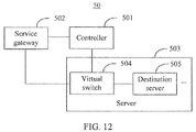
- FIG. 12 is a schematic structural diagram of an OpenFlow communication system according to a first embodiment of the present invention.
- the OpenFlow communication system 50 includes a controller 501, a service gateway 502, and a server 503.
- the service gateway 502 sends a transfer processing request to the controller 501, where the transfer processing request includes an action that needs to be transferred.
- the action is a process of waiting for being processed, or an operation that needs to be executed, or the like.
- the action includes at least one of packet encryption, packet decryption, deep packet inspection, data compression, or data decompression.
- the controller 501 selects one server 503 as the virtual switch 504 according to the action that needs to be transferred and a network topology structure.
- the controller 501 delivers a first flow table to the service gateway 502.
- the service gateway 502 forwards a packet to the virtual switch 504 according to the first flow table.
- the service gateway 502 forwards the packet encapsulated in an IP_IN_IP manner to the virtual switch 504 according to the first flow table.
- an IP of the virtual switch is encapsulated, based on an original packet, into the packet forwarded by the service gateway to the virtual switch. After the virtual switch receives the packet forwarded by the service gateway, the encapsulated IP is removed, and the original packet may be obtained.
- the controller 501 delivers a second flow table to the virtual switch 504, where the second flow table includes an instruction used to instruct the virtual switch 504 to execute the action on the packet.
- the virtual switch 504 executes the action on the packet according to the second flow table and sends a packet obtained after the action is executed to the destination server 505 of the packet.
- the second flow table further includes resource information corresponding to the action, such as key information related to decryption, so that the virtual switch 504 executes the action according to the resource information. If the virtual switch 504 has no flow table sending the packet to the destination server 505 of the packet, the virtual switch 504 sends a PACKET_IN message that requests a processing rule of the packet to the controller 501.
- the controller 501 delivers a third flow table to the virtual switch 504, where the third flow table is used for the virtual switch 504 to send the packet obtained after the action is executed to the destination server 505 of the packet. Therefore, when a processing capability of the service gateway 502 is insufficient, some of data processing services are transferred from the service gateway 502 to a virtual server for execution, which can implement load balance among network elements in a system, improve utilization and a throughput of the system, and further enhance performance of the entire system.
- a transfer processing request sent by a service gateway is received, where the transfer processing request includes an action that needs to be transferred; one server is selected as a virtual switch according to the action that needs to be transferred and a network topology structure; then a first flow table is delivered to the service gateway, where the first flow table is used for the service gateway to forward a packet to the virtual switch; a second flow table is delivered to the virtual switch, where the second flow table includes an instruction used to instruct the virtual switch to execute the action on the packet, so that the virtual switch executes the action on the packet and sends a packet obtained after the action is executed to a destination server of the packet.
Description
- The present invention relates to the communications field, and in particular, to an OpenFlow communication method and system, a controller, and a service gateway.
- With economic and social globalization, an increasing quantity of enterprises and organizations establish branches nationwide and even worldwide, and an increasing quantity of employees on business trips access headquarters' service systems from fixed locations. In addition, as services continuously expand and application becomes increasingly complex, an IT (Information Technology, information technology) infrastructure of an organization is developing toward centralized management, and setting up data centers and cloud services has been a trend of IT construction. An enterprise service gateway is an entrance to a data center and cloud service center. A throughput capability of the enterprise service gateway directly affects performance of the entire data center and cloud service center.
- OpenFlow (Openflow), a new network switching model supporting network innovation researches, was put forward by Stanford University in the United States. The OpenFlow protocol is gradually improved and successfully applied to an actual network, where application of the OpenFlow protocol to a data center network is particularly prominent. As shown in
FIG. 1 , a topology structure of an OpenFlow network includes: anOpenflow controller 11, anOpenflow switch 12, aterminal 13, and links connecting theOpenflow controller 11,Openflow switch 12, andterminal 13. The Openflowcontroller 11 stores a topology structure of an entire network, generates a flow table for a data flow that needs to be forwarded, and delivers the flow table to a corresponding switch. TheOpenflow switch 12 stores flow table information delivered by the Openflowcontroller 11 and performs data forwarding between theOpenflow switches 12 and between theOpenflow switch 12 and theterminal 13. - A topology structure of the data center network is generally a tree structure. The enterprise service gateway, as the entrance (a root) to the data center, is responsible for network forwarding and further needs to perform particular processing on data, for example: in terms of network security, to perform "encryption/decryption, DPI (Deep Packet Inspection, deep packet inspection technology), and the like" on the data; and to perform data compression and decompression, and the like. Specifically, the processing includes:
- 1. The enterprise service gateway receives a client request and performs data processing such as security detection (IPSEC, InternetProtocolSecurity, Internet Protocol Security, and DPI) on data.
- 2. After the data processing is completed, a to-be-processed packet is forwarded to a back-end server according to a service type of the request.
- 3. The server performs processing, and forwards a result of the processing to the enterprise service gateway.
- 4. The enterprise service gateway receives service data, performs particular processing on the service data, and forwards an encapsulated packet to a client.
-
WO 2006091411 A3 discloses that a method for load balancing communication session processing in a data network platform.US2008276093 discloses a system for managing service mobility using an extensible Markup Language (XML) electronic signature.US2013311778 discloses a system and method for secure cloud service delivery in a network environment.US2005027404 discloses an apparatus for controlling communication between units in a vehicle.US2006277303 discloses a method for improving response time for clients requesting network services. - An enterprise service gateway in the prior art serves as an entrance to an entire data center. When a to-be-processed data volume exceeds a capability of the enterprise service gateway, the enterprise service gateway becomes a bottleneck of an entire system whereas a large quantity of computing resources on a back-end server are idle. Therefore, a method for resolving the bottleneck problem needs to be found.
- The invention made is disclosed in the attached set of independent claims. Additional features are disclosed in the set of dependent claims.
- In view of this, embodiments of the present invention provide an OpenFlow communication method and system, a controller, and a service gateway, which can implement load balance among network elements in a system, improve utilization and a throughput of the system, and further enhance performance of the entire system, as defined by the independent claims. Further embodiments are provided by the dependent claims..
- According to a first aspect, an OpenFlow communication method is provided, where the method includes: when load exceeds a preset threshold, receiving by a controller, a transfer processing request sent by a service gateway, where the transfer processing request includes an action that needs to be transferred; selecting, by the controller, one server as a virtual switch according to the action that needs to be transferred and a network topology structure; delivering, by the controller, a first flow table to the service gateway, where the first flow table is used for the service gateway to forward a packet to the virtual switch; and delivering, by the controller a second flow table to the virtual switch, where the second flow table includes an instruction used to instruct the virtual switch to execute the action on the packet, so that the virtual switch executes the action on the packet and sends a packet obtained after the action is executed to a destination server of the packet.
- With reference to an implementation manner of the first aspect, in a first possible implementation manner, the method further includes: if the virtual switch has no flow table for sending the packet to the destination server of the packet, receiving a message that requests a processing rule of the packet and is sent by the virtual switch for the packet; and delivering a third flow table to the virtual switch, where the third flow table is used for the virtual switch to send the packet obtained after the action is executed to the destination server of the packet.
- With reference to the implementation manner of the first aspect, in a second possible implementation manner, the action includes at least one of packet encryption, packet decryption, deep packet inspection, data compression, or data decompression.
- According to a second aspect, a controller is provided, including: a receiving module, configured to receive a transfer processing request sent by a service gateway, when load exceeds a preset threshold, where the transfer processing request includes an action that needs to be transferred; a selection module, configured to select one server as a virtual switch according to the action that needs to be transferred and a network topology structure; a first flow table delivering module, configured to deliver a first flow table to the service gateway, where the first flow table is used for the service gateway to forward a packet to the virtual switch; and a second flow table delivering module, configured to deliver a second flow table to the virtual switch, where the second flow table includes an instruction used to instruct the virtual switch to execute the action on the packet, so that the virtual switch executes the action on the packet and sends a packet obtained after the action is executed to a destination server of the packet.
- With reference to an implementation manner of the second aspect, in a first possible implementation manner, if the virtual switch has no related flow table, the controller further includes a third flow table delivering module, where the receiving module receives a message that requests a processing rule of the packet and is sent by the virtual switch for the packet; and the third delivering module delivers a third flow table to the virtual switch, where the third flow table is used for the virtual switch to send the packet obtained after the action is executed to the destination server of the packet.
- With reference to the implementation manner of the second aspect, in a second possible implementation manner, the action includes at least one of packet encryption, packet decryption, deep packet inspection, data compression, or data decompression.
- According to a third aspect, an OpenFlow communication method is provided, including: when load exceeds a preset threshold, sending, by a service gateway, a transfer processing request to a controller, where the transfer processing request includes an action that needs to be transferred, so that the controller selects one server as a virtual switch; receiving, by the service gateway a flow table delivered by the controller; and forwarding, by a service gateway, a packet to the virtual switch according to the flow table, so that the virtual switch executes the action on the packet and sends a packet obtained after the action is executed to a destination server of the packet.
- With reference to an implementation manner of the third aspect, in a first possible implementation manner, the forwarding a packet to the virtual switch according to the flow table is specifically forwarding the packet encapsulated in an IP_IN_IP manner to the virtual switch according to the flow table.
- With reference to the implementation manner of the third aspect, in a second possible implementation manner, the action includes at least one of packet encryption, packet decryption, deep packet inspection, data compression, or data decompression.
- According to a fourth aspect, a service gateway is provided, including: a sending module, configured to: when load exceeds a preset threshold, send a transfer processing request to a controller, where the transfer processing request includes an action that needs to be transferred, so that the controller selects one server as a virtual switch; a receiving module, configured to receive a flow table delivered by the controller; and a forwarding module, configured to forward a packet to the virtual switch according to the flow table, so that the virtual switch executes the action on the packet and sends a packet obtained after the action is executed to a destination server of the packet.
- With reference to an implementation manner of the fourth aspect, in a first possible implementation manner, the forwarding module is specifically configured to forward the packet encapsulated in an IP_IN_IP manner to the virtual switch according to the flow table.
- With reference to the implementation manner of the fourth aspect, in a second possible implementation manner, the action includes at least one of packet encryption, packet decryption, deep packet inspection, data compression, or data decompression.
- According to a fifth aspect, a controller is provided, including a receiver, a processor, a transmitter, and a memory, where the receiver is configured to receive a transfer processing request sent by a service gateway when load exceeds a preset threshold, where the transfer processing request includes an action that needs to be transferred; the memory is configured to store program code; the processor is connected to the receiver and configured to invoke the program code stored in the memory to execute the following method: selecting one server as a virtual switch according to the action that needs to be transferred and a network topology structure; the transmitter is further configured to deliver a first flow table to the service gateway, where the first flow table is used for the service gateway to forward a packet to the virtual switch; and the transmitter is further configured to deliver a second flow table to the virtual switch, where the second flow table includes an instruction used to instruct the virtual switch to execute the action on the packet, so that the virtual switch executes the action on the packet and sends a packet obtained after the action is executed to a destination server of the packet.
- With reference to an implementation manner of the fifth aspect, in a first possible implementation manner, if the virtual switch has no related flow table, the receiver is further configured to receive a message that requests a processing rule of the packet and is sent by the virtual switch for the packet; and the transmitter delivers a third flow table to the virtual switch, where the third flow table is used for the virtual switch to send the packet obtained after the action is executed to the destination server of the packet.
- With reference to the implementation manner of the fifth aspect, in a second possible implementation manner, the action includes at least one of packet encryption, packet decryption, deep packet inspection, data compression, or data decompression.
- According to a sixth aspect, a service gateway is provided, including a transmitter, receiver, a processor, and a memory, where when load exceeds a preset threshold, the transmitter is configured to send a transfer processing request to a controller, where the transfer processing request includes an action that needs to be transferred, so that the controller selects one server as a virtual switch; the receiver is configured to receive a flow table delivered by the controller; the memory is configured to store program code; and the processor is configured to invoke the program code stored in the memory to execute the following method: forwarding a packet to the virtual switch according to the flow table, so that the virtual switch executes the action on the packet and sends a packet obtained after the action is executed to a destination server of the packet.
- With reference to an implementation manner of the sixth aspect, in a first possible implementation manner, the forwarding a packet to the virtual switch according to the flow table in the method executed by the processor is specifically: forwarding the packet encapsulated in an IP_IN_IP manner to the virtual switch through a first data channel according to the flow table.
- With reference to the implementation manner of the sixth aspect, in a second possible implementation manner, the action includes at least one of packet encryption, packet decryption, deep packet inspection, data compression, or data decompression.
- According to a seventh aspect, an OpenFlow communication system is provided, including a controller, a service gateway, and at least one server, where the service gateway sends a transfer processing request to the controller when load exceeds a preset threshold, where the transfer processing request includes an action that needs to be transferred; the controller selects one server of the at least one server as a virtual switch according to the action that needs to be transferred and a network topology structure; the controller delivers a first flow table to the service gateway; the service gateway forwards a packet to the virtual switch according to the first flow table; the controller delivers a second flow table to the virtual switch, where the second flow table includes an instruction used to instruct the virtual switch to execute the action on the packet; and the virtual switch executes the action on the packet first possible implementation manner, if the virtual switch has no flow table for sending the packet to the destination server of the packet, the virtual switch is further configured to send, to the controller, a message that requests a processing rule of the packet; and the controller is further configured to deliver a third flow table to the virtual switch, where the third flow table is used for the virtual switch to send the packet obtained after the action is executed to the destination server of the packet.
- With reference to the implementation manner of the seventh aspect, in a second possible implementation manner, the action includes at least one of packet encryption, packet decryption, deep packet inspection, data compression, or data decompression.
- With reference to the implementation manner of the seventh aspect, in a third possible implementation manner, that the service gateway is configured to forward a packet to the virtual switch according to the first flow table is specifically: forward the packet encapsulated in an IP_IN_IP manner to the virtual switch according to the first flow table.
- According to the present invention, a transfer processing request that indicates that transfer is needed and is sent by a service gateway is received, where the transfer processing request includes an action that needs to be transferred; one server is selected as a virtual switch according to the action that needs to be transferred and a network topology structure; a first flow table is delivered to the service gateway for the service gateway to forward a packet to the virtual switch; a second flow table is delivered to the virtual switch, where the second flow table includes an instruction used to instruct the virtual switch to execute the action on the packet, so that the virtual switch executes the action on the packet and sends a packet obtained after the action is executed to a destination server of the packet, thereby implementing load balance among network elements in a system, improving utilization and a throughput of the system, and further enhancing performance of the entire system.
- To describe the technical solutions in the embodiments of the present invention or in the prior art more clearly, the following briefly introduces the accompanying drawings required for describing the embodiments or the prior art. Apparently, the accompanying drawings in the following description show some embodiments of the present invention, and a person of ordinary skill in the art may still derive other drawings from these accompanying drawings without creative efforts.
-
FIG. 1 is a diagram of an OpenFlow network topology structure in the prior art; -
FIG. 2 is a diagram of an OpenFlow network topology structure according to the present invention; -
FIG. 3 is a schematic diagram of a format of a message reported by a service gateway to a controller inFIG. 2 ; -
FIG. 4 is a schematic diagram of formats of messages delivered by a controller inFIG. 2 ; -
FIG. 5 is a schematic diagram of a format of a message of a second flow table delivered by a controller inFIG. 2 ; -
FIG. 6 is a schematic flowchart of an OpenFlow communication method according to a first embodiment of the present invention; -
FIG. 7 is a schematic structural diagram of a controller according to a first embodiment of the present invention; -
FIG. 8 is a schematic flowchart of an OpenFlow communication method according to a second embodiment of the present invention; -
FIG. 9 is a schematic structural diagram of a service gateway according to a first embodiment of the present invention; -
FIG. 10 is a schematic structural diagram of a controller according to a second embodiment of the present invention; -
FIG. 11 is a schematic structural diagram of a service gateway according to a second embodiment of the present invention; and -
FIG. 12 is a schematic structural diagram of an OpenFlow communication system according to a first embodiment of the present invention. - To make the objectives, technical solutions, and advantages of the embodiments of the present invention clearer, the following clearly and completely describes the technical solutions in the embodiments of the present invention with reference to the accompanying drawings in the embodiments of the present invention. Apparently, the described embodiments are some but not all of the embodiments of the present invention. All other embodiments obtained by a person of ordinary skill in the art based on the embodiments of the present invention without creative efforts shall fall within the protection scope of the present invention.
- Referring to
FIG. 2, FIG. 2 is a diagram of an OpenFlow network topology structure according to the present invention. As shown inFIG. 2 , an OpenFlow network topology includes aservice gateway 22, acontroller 21, avirtual switch 23, adestination server 24, and arouter 25. Taking decryption as an example, when a packet decryption request is received, theservice gateway 22 checks load of a system; and if the load exceeds a given threshold, that is, a processing capability of theservice gateway 22 is insufficient, executes the following process with reference toFIG. 2 : - 1. The
service gateway 22 reports, to thecontroller 21, a requested resource that needs to be transferred. The requested resource that needs to be transferred corresponds to an action (Action), where the action is a process of waiting for being processed, or an operation that needs to be executed, or the like. Assuming that the action herein is a decryption action, the requested resource that needs to be transferred is related to decryption. Theservice gateway 22 reports, to thecontroller 21 in a form of a resource request message, the requested resource that needs to be transferred. A specific format of the resource request message is shown inFIG. 3 . The IP (Internet Protocol, Internet Protocol) includes a source IP and a destination IP. The source IP is an IP address of theservice gateway 22, and the destination IP is an IP address of thecontroller 21. The TCP (Transmission Control Protocol, Transmission Control Protocol) indicates that the resource request message is transmitted through a TCP protocol port, which is preferably a 6633 port in this embodiment. The OF indicates that a transmission process of the resource request message strictly complies with the openflow (OpenFlow) protocol. A value of S_req is 1, representing that the message is a resource request. Req_type represents a type of the message request, where a data length of the Req_type is 4 bytes; preferably, 1 is an encryption resource, 2 is a decryption resource, and 3 is a compression resource. In other embodiments of the present invention, the action may be another action, for example, a decompression action and DPI (Deep Packet Inspection, deep packet inspection technology) scanning. Different actions correspond to different requested resources that need to be transferred. In this embodiment, that theservice gateway 22 sends the resource request message to thecontroller 21 indicates that a resource, that is, a decryption resource, is requested according to the openflow protocol. - 2. The
controller 21 selects, according to a needed resource reported by theservice gateway 22 and a network topology structure, one appropriate server from a back-end switch cluster as thevirtual switch 23, of which a distance from a destination server is preferably a shortest path if possible. - 3. The
controller 21 delivers a first flow table, to establish a first data channel between theservice gateway 22 and thevirtual switch 23, where the first data channel is used for theservice gateway 22 to forward a packet to thevirtual switch 23. Specifically, thecontroller 21 delivers the first flow table to theservice gateway 22. A format of the first flow table is shown in (a) ofFIG. 4 , where F_add indicates addition of a flow table. PUSH_IPHEAD filled in the Action means an operation of adding an IP header. Meanings of the IP, TCP, and OF are the same as those in the resource request message inFIG. 3 , and details are not described herein again. Thecontroller 21 further delivers a first flow table to thevirtual switch 23. A format of the first flow table is shown in (b) ofFIG. 4 . POP_IPHEAD filled in the Action means an operation of deleting an IP header. In this embodiment of the present invention, data is transmitted between theservice gateway 22 and thevirtual switch 23 in an IP_IN_IP (encapsulating an IP in another IP) manner. To-be-transmitted data is a packet existing before theservice gateway 22 performs a flow table operation, that is, an original packet, as shown in (c) ofFIG. 4 . Based on this, theservice gateway 22 executes an operation of encapsulating "VGW_IP" according to the flow table, to obtain a packet format generated after the flow table operation, where "VGW_IP" is an IP of thevirtual switch 23, as shown in (d) ofFIG. 4 . Theservice gateway 22 sends a packet obtained after the flow table operation to thevirtual switch 23, to obtain the packet format, as shown in (e) ofFIG. 4 , existing before thevirtual switch 23 executes a flow table operation. Thevirtual switch 23 executes the flow table operation of deleting an IP header, to obtain a packet format, as shown in (f) ofFIG. 4 , generated after the flow table operation. Certainly, in other embodiments of the present invention, data may be transmitted in another manner, such as direct modification to a MAC (Media Access Control, Media Access Control) address. At the same time when theservice gateway 22 establishes the first data channel with thevirtual switch 23 and transmits the data, thecontroller 21 further delivers a second flow table to the selectedvirtual switch 23. The second flow table includes an instruction used to instruct thevirtual switch 23 to execute an action on the packet. A format of the second flow table delivered by thecontroller 21 to thevirtual switch 23 is shown inFIG. 5 , where a to-be-executed action is decryption, and KEY and KEY_LEN respectively mean a key and a length of the key. - 4. The
virtual switch 23 executes the decryption action, to obtain original packet information. - 5. The
virtual switch 23 forwards the packet to thedestination server 24 according to the original packet information. If thevirtual switch 23 has no related flow table, a PACKET_IN message that requests a processing rule of the packet and is for the packet is sent to thecontroller 21; thecontroller 21 delivers a third flow table to establish a second data channel between thevirtual switch 23 and thedestination server 24, where the second data channel is used for thevirtual switch 23 to send the packet obtained after the action is executed to thedestination server 24 of the packet. In this embodiment of the present invention, thedestination server 24 and thevirtual switch 23 may be or may not be a same server. When thecontroller 21 establishes the second data channel between thevirtual switch 23 and thedestination server 24, thevirtual switch 23 may establish the second data channel with the destination server by using therouter 25. - In this way, when the
service gateway 22 detects that the load of the system exceeds the given threshold, thecontroller 21 transfers the action of theservice gateway 22 to thevirtual switch 23 for execution. Subsequently, if theservice gateway 22 receives an action request and detects that the load of the system exceeds the given threshold, theservice gateway 22 repeats execution of the foregoing process to transfer an action of theservice gateway 22 to thevirtual switch 23 for execution until theservice gateway 22 has not receives the action request any more or has not detected that the load of the system exceeds the given threshold. In this case, the system is stable. In this way, when a processing capability of theservice gateway 22 is insufficient, some of data processing services are transferred from theservice gateway 22 to thevirtual switch 23 for execution, which can implement load balance among network elements in the system, improve utilization and a throughput of the system, and further enhance performance of the entire system. - Referring to
FIG. 6, FIG. 6 is a schematic flowchart of an OpenFlow communication method according to a first embodiment of the present invention. As shown inFIG. 6 , the OpenFlow communication method includes: - S10. Receive a transfer processing request sent by a service gateway, where the transfer processing request includes an action that needs to be transferred.
The action is a process of waiting for being processed, or an operation that needs to be executed, or the like. The action includes at least one of packet encryption, packet decryption, deep packet inspection, data compression, or data decompression. In S10, when the service gateway detects that load of a system exceeds a given threshold, the action needs to be transferred. Receiving the action that needs to be transferred and is sent by the service gateway is receiving a requested resource that is related to the action and sent by the service gateway, so that the action is transferred to another network element for execution. - S11. Select one server as a virtual switch according to the action that needs to be transferred and a network topology structure.
- S12. Deliver a first flow table to the service gateway, where the first flow table is used for the service gateway to forward a packet to the virtual switch.
In S12, at the same time when the first flow table is delivered to the service gateway, a first flow table is further delivered to the virtual switch. The first flow table delivered to the service gateway indicates an operation of adding an IP header, which means that an IP of the virtual switch is encapsulated, based on an original packet, into the packet forwarded by the service gateway to the virtual switch. The first flow table delivered to the virtual switch indicates an operation of deleting the IP header, that is, removing the encapsulated IP from the received packet forwarded by the service gateway, so that the virtual switch may acquire the original packet. - S13. Deliver a second flow table to the virtual switch, where the second flow table includes an instruction used to instruct the virtual switch to execute the action on the packet, so that the virtual switch executes the action on the packet and sends a packet obtained after the action is executed to a destination server of the packet. Preferably, the delivered second flow table further includes resource information corresponding to the action, so that the virtual switch executes the action on the packet according to the resource information. For example, a decryption operation is executed according to key information related to decryption.
- In S13, the action includes at least one of packet encryption, packet decryption, deep packet inspection, data compression, or data decompression. The resource information corresponding to the action includes a key, a DPI rule, or the like. In this way, when a processing capability of the service gateway is insufficient, some of data processing services are transferred from the service gateway to a virtual server for execution, which can implement load balance among network elements in the system, improve utilization and a throughput of the system, and further enhance performance of the entire system.
- If the virtual switch has no flow table for sending the packet to the destination server of the packet, a PACKET_IN message sent by the virtual switch is received, and a third flow table is generated. The third flow table is delivered to the virtual switch to establish a second data channel between the virtual switch and the destination server, where the third flow table is used for the virtual switch to send the packet obtained after the action is executed to the destination server of the packet. In this embodiment of the present invention, the destination server and the virtual switch may be or may not be a same server. When the second data channel is established between the virtual switch and the destination server, the second data channel may be established between the virtual switch and the destination server by using a router.
- Referring to
FIG. 7, FIG. 7 is a schematic structural diagram of a controller according to a first embodiment of the present invention. As shown inFIG. 7 , thecontroller 10 includes a receivingmodule 101, aselection module 102, a first flowtable delivering module 103, a second flowtable delivering module 104, and a third flowtable delivering module 105. - The receiving
module 101 is configured to receive a transfer processing request sent by a service gateway, where the transfer processing request includes an action that needs to be transferred. Theselection module 102 is connected to the receivingmodule 101 and configured to select one server as a virtual switch according to the action that needs to be transferred and a network topology structure. The action is a process of waiting for being processed, or an operation that needs to be executed, or the like. The action includes at least one of packet encryption, packet decryption, deep packet inspection, data compression, or data decompression. The first flowtable delivering module 103 is connected to theselection module 102 and configured to deliver a first flow table to the service gateway to establish a first data channel between the service gateway and the virtual switch, where the first flow table is used for the service gateway to forward a packet to the virtual switch. In this embodiment of the present invention, at the same time when the first flowtable delivering module 103 delivers the first flow table to the service gateway, the first flowtable delivering module 103 further delivers a first flow table to the virtual switch. The first flow table delivered to the service gateway indicates an operation of adding an IP header, which means that an IP of the virtual switch is encapsulated, based on an original packet, into the packet forwarded by the service gateway to the virtual switch. The first flow table delivered to the virtual switch indicates an operation of deleting the IP header, that is, removing the encapsulated IP from the received packet forwarded by the service gateway, so that the virtual switch may acquire the original packet. The second flowtable delivering module 104 is connected to theselection module 102 and the first deliveringmodule 103 and configured to deliver a second flow table to the virtual switch, where the second flow table includes an instruction used to instruct the virtual switch to execute the action on the packet, so that the virtual switch executes the action on the packet and sends a packet obtained after the action is executed to a destination server of the packet. Further, the second flow table further includes resource information corresponding to the action, where the resource information includes information related to an operation of executing the action, such as a key or a DPI rule. In this embodiment of the present invention, the virtual switch has no flow table for sending the packet to the destination server of the packet, the receivingmodule 101 is further configured to receive a PACKET_IN message that is sent by the virtual switch for the packet. The third flowtable delivering module 105 delivers a third flow table to the virtual switch to establish a second data channel between the virtual switch and the destination server, where the third flow table is used for the virtual switch to send the packet obtained after the action is executed to the destination server of the packet. In this way, when a processing capability of the service gateway is insufficient, some of data processing services are transferred from the service gateway to a virtual server for execution, which can implement load balance among network elements in a system, improve utilization and a throughput of the system, and further enhance performance of the entire system. - Referring to
FIG. 8, FIG. 8 is a schematic flowchart of an OpenFlow communication method according to a second embodiment of the present invention. As shown inFIG. 8 , the OpenFlow communication method includes: - S20. When load exceeds a preset threshold, send a transfer processing request to a controller, where the transfer processing request includes an action that needs to be transferred, so that the controller selects one server as a virtual switch. The action is a process of waiting for being processed, or an operation that needs to be executed, or the like. The action includes at least one of packet encryption, packet decryption, deep packet inspection, data compression, or data decompression.
- S21. Receive a flow table delivered by the controller.
- S22. Forward a packet to the virtual switch according to the flow table, so that the virtual switch executes the action on the packet and sends a packet obtained after the action is executed to a destination server of the packet. In S32, the packet encapsulated in an IP_IN_IP manner is forwarded to the virtual switch according to the flow table. Specifically, an IP of the virtual switch is encapsulated, based on an original packet, into the packet forwarded by the service gateway to the virtual switch. After the virtual switch receives the packet forwarded by the service gateway, the encapsulated IP is removed, and the original packet may be obtained.
- In this embodiment of the present invention, when load exceeds a preset threshold, some of data processing services are transferred from a service gateway to a virtual server for execution, which can implement load balance among network elements in a system, improve utilization and a throughput of the system, and further enhance performance of the entire system.
- Referring to
FIG. 9, FIG. 9 is a schematic structural diagram of a service gateway according to a first embodiment of the present invention. As shown inFIG. 9 , theservice gateway 20 includes a sendingmodule 201, a receivingmodule 202, and aforwarding module 203. - The sending
module 201 is configured to: when load exceeds a preset threshold, send a transfer processing request to a controller, where the transfer processing request includes an action that needs to be transferred, so that the controller selects one server as a virtual switch. The action is a process of waiting for being processed, or an operation that needs to be executed, or the like. The action includes at least one of packet encryption, packet decryption, deep packet inspection, data compression, or data decompression. The receivingmodule 202 is connected to the sendingmodule 201 and configured to receive a flow table delivered by the controller. Theforwarding module 203 is connected to the receivingmodule 202 and configured to forward a packet to the virtual switch according to the flow table, so that the virtual switch executes the action on the packet and sends a packet obtained after the action is executed to a destination server of the packet. Theforwarding module 203 forwards the packet encapsulated in an IP_IN_IP manner to the virtual switch according to the packet. Specifically, an IP of the virtual switch is encapsulated, based on an original packet, into the packet forwarded by the service gateway to the virtual switch. After the virtual switch receives the packet forwarded by the service gateway, the encapsulated IP is removed, and the original packet may be obtained. - In this embodiment of the present invention, when load exceeds a preset threshold, a sending
module 201 sends a transfer processing request to a controller, where the transfer processing request includes an action that needs to be transferred, so that the controller selects one server as a virtual switch; areceiving module 202 receives a flow table delivered by the controller; aforwarding module 203 forwards a packet to the virtual switch according to the data flow table, so that the virtual switch executes the action on the packet and sends a packet obtained after the action is executed to a destination server of the packet. In this way, when a processing capability of the service gateway is insufficient, some of data processing services are transferred from the service gateway to a virtual server for execution, which can implement load balance among network elements in a system, improve utilization and a throughput of the system, and further enhance performance of the entire system. - Referring to
FIG. 10, FIG. 10 is a schematic structural diagram of a controller according to a second embodiment of the present invention. As shown inFIG. 10 , thecontroller 30 includes areceiver 301, aprocessor 302, atransmitter 303, amemory 304, and adata bus 305. Thereceiver 301, theprocessor 302, thetransmitter 303, and thememory 304 are connected by using thedata bus 305 for mutual communication. - In this embodiment of the present invention, the
receiver 301 is configured to receive a transfer processing request sent by a service gateway, where the transfer processing request includes an action that needs to be transferred. The memory is configured to store program code. Theprocessor 302 is configured to invoke the program code stored in the memory to execute the following method: selecting one server as a virtual switch according to the action that needs to be transferred and a network topology structure. The action is a process of waiting for being processed, or an operation that needs to be executed, or the like. The action includes at least one of packet encryption, packet decryption, deep packet inspection, data compression, or data decompression. Thetransmitter 303 delivers a first flow table to the service gateway to establish a first data channel between the service gateway and the virtual switch, where the first flow table is used for the service gateway to forward a packet to the virtual switch. In this embodiment of the present invention, at the same time when thetransmitter 303 delivers the first flow table to the service gateway, a first flow table is further delivered to the virtual switch. The first flow table delivered to the service gateway indicates an operation of adding an IP header, which means that an IP of the virtual switch is encapsulated, based on an original packet, into the packet forwarded by the service gateway to the virtual switch. The first flow table delivered to the virtual switch indicates an operation of deleting the IP header, that is, removing the encapsulated IP from the received packet forwarded by the service gateway, so that the virtual switch may acquire the original packet. - The
transmitter 303 further delivers a second flow table to the virtual switch, where the second flow table includes an instruction used to instruct the virtual switch to execute the action on the packet, so that the virtual switch executes the action on the packet and sends a packet obtained after the action is executed to a destination server of the packet. The second flow table may further include resource information corresponding to the action, where the resource information corresponding to the action includes a key, a DPI rule, or the like. Thememory 304 is further configured to store the network topology structure, the first flow table delivered by thetransmitter 403 to the service gateway, and the second flow table delivered by thetransmitter 403 to the virtual switch. If the virtual switch has no related flow table, the receiver receives a PACKET_IN message sent by the virtual switch. The transmitter delivers a third flow table to the virtual switch, where the third flow table is used for the virtual switch to send the packet obtained after the action is executed to the destination server of the packet. In this embodiment of the present invention, some of data processing services are transferred from a service gateway to a virtual server for execution, which can implement load balance among network elements in a system, improve utilization and a throughput of the system, and further enhance performance of the entire system. - Referring to
FIG. 11, FIG. 11 is a schematic structural diagram of a service gateway according to a second embodiment of the present invention. As shown inFIG. 11 , theservice gateway 40 includes areceiver 401, aprocessor 402, atransmitter 403, amemory 404, and acommunications bus 405. Thereceiver 401,processor 402,transmitter 403, andmemory 404 are connected by using thedata bus 405 for mutual communication. - In this embodiment of the present invention, when load exceeds a preset threshold, a
transmitter 403 is configured to send a transfer processing request to a controller, where the transfer processing request includes an action that needs to be transferred, so that the controller selects one server as a virtual switch. The action is a process of waiting for being processed, or an operation that needs to be executed, or the like. The action includes at least one of packet encryption, packet decryption, deep packet inspection, data compression, or data decompression. Areceiver 401 is configured to receive a flow table delivered by the controller. A memory is configured to store program code. The memory is further configured to store the flow table. Theprocessor 402 invokes the program code stored in the memory to execute the following method: forwarding a packet to the virtual switch according to the flow table, so that the virtual switch executes the action on the packet and sends a packet obtained after the action is executed to a destination server of the packet. In a method executed by theprocessor 402, the packet encapsulated in an IP_IN_IP manner is forwarded to the virtual switch according to the flow table. Specifically, an IP of the virtual switch is encapsulated, based on an original packet, into the packet forwarded by the service gateway to the virtual switch. After the virtual switch receives the packet forwarded by the service gateway, the encapsulated IP is removed, and the original packet may be obtained. Thememory 404 stores the action that needs to be transferred and the flow table delivered by the controller. In this embodiment of the present invention, when load exceeds a preset threshold, some of data processing services are transferred from the service gateway to a virtual server for execution, which can implement load balance among network elements in a system, improve utilization and a throughput of the system, and further enhance performance of the entire system. - Referring to
FIG. 12, FIG. 12 is a schematic structural diagram of an OpenFlow communication system according to a first embodiment of the present invention. As shown inFIG. 12 , theOpenFlow communication system 50 includes acontroller 501, aservice gateway 502, and aserver 503. There aremultiple servers 503 and one of the multiple servers may be selected as avirtual switch 504 or adestination server 505. Theservice gateway 502 sends a transfer processing request to thecontroller 501, where the transfer processing request includes an action that needs to be transferred. The action is a process of waiting for being processed, or an operation that needs to be executed, or the like. The action includes at least one of packet encryption, packet decryption, deep packet inspection, data compression, or data decompression. Thecontroller 501 selects oneserver 503 as thevirtual switch 504 according to the action that needs to be transferred and a network topology structure. Thecontroller 501 delivers a first flow table to theservice gateway 502. Theservice gateway 502 forwards a packet to thevirtual switch 504 according to the first flow table. Specifically, theservice gateway 502 forwards the packet encapsulated in an IP_IN_IP manner to thevirtual switch 504 according to the first flow table. Specifically, an IP of the virtual switch is encapsulated, based on an original packet, into the packet forwarded by the service gateway to the virtual switch. After the virtual switch receives the packet forwarded by the service gateway, the encapsulated IP is removed, and the original packet may be obtained. Thecontroller 501 delivers a second flow table to thevirtual switch 504, where the second flow table includes an instruction used to instruct thevirtual switch 504 to execute the action on the packet. Thevirtual switch 504 executes the action on the packet according to the second flow table and sends a packet obtained after the action is executed to thedestination server 505 of the packet. Further, the second flow table further includes resource information corresponding to the action, such as key information related to decryption, so that thevirtual switch 504 executes the action according to the resource information. If thevirtual switch 504 has no flow table sending the packet to thedestination server 505 of the packet, thevirtual switch 504 sends a PACKET_IN message that requests a processing rule of the packet to thecontroller 501. Thecontroller 501 delivers a third flow table to thevirtual switch 504, where the third flow table is used for thevirtual switch 504 to send the packet obtained after the action is executed to thedestination server 505 of the packet. Therefore, when a processing capability of theservice gateway 502 is insufficient, some of data processing services are transferred from theservice gateway 502 to a virtual server for execution, which can implement load balance among network elements in a system, improve utilization and a throughput of the system, and further enhance performance of the entire system. - In conclusion, according to the present invention, a transfer processing request sent by a service gateway is received, where the transfer processing request includes an action that needs to be transferred; one server is selected as a virtual switch according to the action that needs to be transferred and a network topology structure; then a first flow table is delivered to the service gateway, where the first flow table is used for the service gateway to forward a packet to the virtual switch; a second flow table is delivered to the virtual switch, where the second flow table includes an instruction used to instruct the virtual switch to execute the action on the packet, so that the virtual switch executes the action on the packet and sends a packet obtained after the action is executed to a destination server of the packet. When a processing capability of the service gateway is insufficient, some of data processing services are transferred from the service gateway to a virtual server for execution, which can implement load balance among network elements in a system, improve utilization and a throughput of the system, and further enhance performance of the entire system.
- The foregoing descriptions are merely embodiments of the present invention, and the protection scope of the present invention is not limited thereto. All equivalent structure or process changes made according to the content of this specification and accompanying drawings in the present invention or by directly or indirectly applying the present invention in other related technical fields shall fall within the protection scope of the present invention.
Claims (13)
- An OpenFlow communication method, wherein the method comprises:when load exceeds a preset threshold,receiving (S10), by a controller (10, 30, 501), a transfer processing request sent by a service gateway (20, 40, 502), wherein the transfer processing request comprises an action that needs to be transferred;selecting (S11), by the controller (10, 30, 501), one server as a virtual switch (504) according to the action that needs to be transferred and a network topology structure;delivering (S12), by the controller (10, 30, 501), a first flow table to the service gateway (20, 40, 502), wherein the first flow table is used for the service gateway (20, 40, 502) to forward a packet to the virtual switch (504); anddelivering (S13), by the controller (10, 30, 501), a second flow table to the virtual switch (504), wherein the second flow table comprises an instruction used to instruct the virtual switch (504) to execute the action on the packet, so that the virtual switch (504) executes the action on the packet and sends the packet obtained after the action is executed to a destination server (505) of the packet.
- The method according to claim 1, wherein the method further comprises: if the virtual switch has no flow table for sending the packet to the destination server of the packet,
receiving a message that requests a processing rule of the packet and is sent by the virtual switch (504) for the packet; and
delivering a third flow table to the virtual switch (504), wherein the third flow table is used for the virtual switch to send the packet obtained after the action is executed to the destination server (505) of the packet. - The method according to claim 1, wherein the action comprises at least one of packet encryption, packet decryption, deep packet inspection, data compression, or data decompression.
- A controller (10, 30, 501), wherein the controller comprises:a receiving module (101), configured to receive a transfer processing request sent by a service gateway(20, 40, 502) when load exceeds a preset threshold, wherein the transfer processing request comprises an action that needs to be transferred;a selection module (102), configured to select one server as a virtual switch (504) according to the action that needs to be transferred and a network topology structure;a first flow table delivering module (103), configured to deliver a first flow table to the service gateway (20, 40, 502), wherein the first flow table is used for the service gateway (20, 40, 502)to forward a packet to the virtual switch (504); anda second flow table delivering module (104), configured to deliver a second flow table to the virtual switch (504), wherein the second flow table comprises an instruction used to instruct the virtual switch (504) to execute the action on the packet, so that the virtual switch (504) executes the action on the packet and sends the packet obtained after the action is executed to a destination server (505) of the packet.
- The controller (10, 30, 501) according to claim 4, wherein if the virtual switch (504) has no flow table for sending the packet to the destination server (505) of the packet, the controller further comprises a third flow table delivering module (105), wherein
the receiving module (101) receives a message that requests a processing rule of the packet and is sent by the virtual switch (504) for the packet; and
the third flow table delivering module delivers a third flow table to the virtual switch (504), wherein the third flow table is used for the virtual switch (504) to send the packet obtained after the action is executed to the destination server (505) of the packet. - The controller (10, 30, 501) according to claim 4, wherein the action comprises at least one of packet encryption, packet decryption, deep packet inspection, data compression, or data decompression.
- An OpenFlow communication method, wherein the method comprises:when load exceeds a preset threshold, sending (S20), by a service gateway (20, 40, 502), a transfer processing request to a controller (10, 30, 501), wherein the transfer processing request comprises an action that needs to be transferred, so that the controller (10, 30, 501) selects one server as a virtual switch (504);receiving (S21), by the service gateway (20, 40, 502), a flow table delivered by the controller (10, 30, 501); andforwarding (S22), by the service gateway (20, 40, 502), a packet to the virtual switch (504) according to the flow table, so that the virtual switch (504) executes the action on the packet and sends a packet obtained after the action is executed to a destination server (505) of the packet.
- The method according to claim 7, wherein the forwarding a packet to the virtual switch (504) according to the flow table is specifically forwarding the packet encapsulated in an IP_IN_IP manner to the virtual switch (504) according to the flow table.
- The method according to claim 7, wherein the action comprises at least one of packet encryption, packet decryption, deep packet inspection, data compression, or data decompression.
- A service gateway (20, 40, 502), wherein the service gateway (20, 40, 502) comprises:a sending module (201), configured to: when load exceeds a preset threshold, send a transfer processing request to a controller (10, 30, 501), wherein the transfer processing request comprises an action that needs to be transferred, so that the controller selects one server as a virtual switch (504);a receiving module (202), configured to receive a flow table delivered by the controller (10, 30, 501); anda forwarding module (203), configured to forward a packet to the virtual switch (504) according to the flow table, so that the virtual switch (504) executes the action on the packet and sends a packet obtained after the action is executed to a destination server (505) of the packet.
- The service gateway (20, 40, 502) according to claim 10, wherein the forwarding module is specifically configured to forward the packet encapsulated in an IP_IN_IP manner to the virtual switch (504) according to the flow table.
- The service gateway (20, 40, 502) according to claim 10, wherein the action comprises at least one of packet encryption, packet decryption, deep packet inspection, data compression, or data decompression.
- An OpenFlow communication system (50), wherein the system (50) comprises a controller (10, 30, 501) according to any one of claims 4-6, a service gateway (20, 40, 502) according to any one of claims 10-12, and at least one server.
Applications Claiming Priority (1)
| Application Number | Priority Date | Filing Date | Title |
|---|---|---|---|
| PCT/CN2014/079084 WO2015184586A1 (en) | 2014-06-03 | 2014-06-03 | Openflow communication method, system, controller, and service gateway |
Publications (3)
| Publication Number | Publication Date |
|---|---|
| EP3142306A1 EP3142306A1 (en) | 2017-03-15 |
| EP3142306A4 EP3142306A4 (en) | 2017-06-14 |
| EP3142306B1 true EP3142306B1 (en) | 2019-01-09 |
Family
ID=54765928
Family Applications (1)
| Application Number | Title | Priority Date | Filing Date |
|---|---|---|---|
| EP14894130.5A Active EP3142306B1 (en) | 2014-06-03 | 2014-06-03 | Openflow communication method, system, controller, and service gateway |
Country Status (6)
| Country | Link |
|---|---|
| US (1) | US10148565B2 (en) |
| EP (1) | EP3142306B1 (en) |
| JP (1) | JP6395867B2 (en) |
| KR (1) | KR101938623B1 (en) |
| CN (1) | CN106464596B (en) |
| WO (1) | WO2015184586A1 (en) |
Families Citing this family (9)
| Publication number | Priority date | Publication date | Assignee | Title |
|---|---|---|---|---|
| US9820316B2 (en) * | 2013-03-15 | 2017-11-14 | Aerohive Networks, Inc. | Preventing asymmetric routing using network tunneling |
| CN106713182B (en) * | 2015-08-10 | 2020-10-09 | 华为技术有限公司 | Method and device for processing flow table |
| US10489275B2 (en) * | 2016-10-20 | 2019-11-26 | Cisco Technology, Inc. | Agentless distributed monitoring of microservices through a virtual switch |
| CN107800696B (en) * | 2017-10-23 | 2020-07-03 | 国云科技股份有限公司 | Method for identifying communication counterfeiting source on cloud platform virtual switch |
| US11190458B2 (en) * | 2017-11-15 | 2021-11-30 | Vmware, Inc. | Network functions support for serverless and granular computing environments |
| CN109450811B (en) * | 2018-11-30 | 2022-08-12 | 新华三云计算技术有限公司 | Flow control method and device and server |
| CN111327437B (en) * | 2018-12-14 | 2023-04-07 | 中国电信股份有限公司 | Flow table processing method, flow table processing device, and SDN network system |
| US11360798B2 (en) * | 2019-11-25 | 2022-06-14 | Nutanix, Inc. | System and method for internal scalable load service in distributed object storage system |
| CN110933118B (en) * | 2020-02-20 | 2020-09-11 | 深圳市城市交通规划设计研究中心股份有限公司 | Edge computing gateway secure communication method, system, terminal equipment and server |
Family Cites Families (39)
| Publication number | Priority date | Publication date | Assignee | Title |
|---|---|---|---|---|
| JP4466188B2 (en) * | 2003-07-16 | 2010-05-26 | 株式会社デンソー | Vehicle control device |
| KR100818977B1 (en) | 2004-05-20 | 2008-04-07 | 프리비트 가부시키가이샤 | Server for routing connection to client device |
| US20060187838A1 (en) * | 2005-02-24 | 2006-08-24 | Utstarcom, Inc. | Method and system for load balancing in a network platform |
| US20060277303A1 (en) * | 2005-06-06 | 2006-12-07 | Nikhil Hegde | Method to improve response time when clients use network services |
| US7693073B2 (en) * | 2006-10-13 | 2010-04-06 | At&T Intellectual Property I, L.P. | System and method for routing packet traffic |
| KR100914430B1 (en) * | 2007-05-02 | 2009-08-28 | 인하대학교 산학협력단 | Service mobility management system using xml security and the method thereof |
| CN101635702B (en) * | 2008-07-21 | 2013-04-03 | 山石网科通信技术(北京)有限公司 | Method for forwarding data packet using security strategy |
| WO2011049135A1 (en) * | 2009-10-23 | 2011-04-28 | 日本電気株式会社 | Network system, control method thereof, and controller |
| US8640127B2 (en) * | 2010-09-21 | 2014-01-28 | International Business Machines Corporation | Relocating guest machine using proxy tool having multiple virtual machines where one virtual machines provides host route for relocation |
| EP2629463B1 (en) | 2010-10-15 | 2019-09-04 | Nec Corporation | Switching system, and monitoring centralization management method |
| CN103168453B (en) | 2010-10-15 | 2016-08-03 | 日本电气株式会社 | Switch system and data forwarding method |
| CN101980490B (en) * | 2010-12-01 | 2012-09-26 | 杭州华三通信技术有限公司 | Link establishment method for virtual switch and physical switch and device thereof |
| CN105262683B (en) * | 2011-01-13 | 2021-03-30 | 日本电气株式会社 | Network system and route control method |
| KR101562726B1 (en) * | 2011-05-30 | 2015-10-22 | 닛본 덴끼 가부시끼가이샤 | Communication path control system, and communication path control method |
| JP5790312B2 (en) * | 2011-08-25 | 2015-10-07 | 富士通株式会社 | COMMUNICATION METHOD, COMMUNICATION DEVICE, AND COMMUNICATION PROGRAM |
| WO2013086204A1 (en) * | 2011-12-07 | 2013-06-13 | Citrix Systems, Inc. | Controlling a network interface using virtual switch proxying |
| US8923296B2 (en) * | 2012-02-23 | 2014-12-30 | Big Switch Networks, Inc. | System and methods for managing network packet forwarding with a controller |
| US8862883B2 (en) * | 2012-05-16 | 2014-10-14 | Cisco Technology, Inc. | System and method for secure cloud service delivery with prioritized services in a network environment |
| CN104272668B (en) * | 2012-05-23 | 2018-05-22 | 博科通讯系统有限公司 | Layer 3 covers gateway |
| US9064216B2 (en) * | 2012-06-06 | 2015-06-23 | Juniper Networks, Inc. | Identifying likely faulty components in a distributed system |
| CN102884763B (en) * | 2012-06-30 | 2015-05-13 | 华为技术有限公司 | Cross-data-center virtual machine migration method, service control gateway and system |
| US9668161B2 (en) * | 2012-07-09 | 2017-05-30 | Cisco Technology, Inc. | System and method associated with a service flow router |
| CN103259727B (en) * | 2012-08-31 | 2016-12-28 | 杭州华三通信技术有限公司 | A kind of message forwarding method and equipment |
| CN102843300A (en) | 2012-09-12 | 2012-12-26 | 盛科网络(苏州)有限公司 | Method and system for achieving controller load balance in Openflow switchboard system |
| US9787570B2 (en) * | 2012-10-17 | 2017-10-10 | Verizon Patent And Licensing Inc. | Dynamic feature peer network for application flows |
| CN104040964B (en) * | 2012-12-06 | 2017-06-20 | 华为技术有限公司 | Method, device and data center network across service area communication |
| CN103179046B (en) | 2013-04-15 | 2016-03-30 | 昆山天元昌电子有限公司 | Based on data center's flow control methods and the system of openflow |
| CN104168184B (en) * | 2013-05-17 | 2017-07-14 | 新华三技术有限公司 | Message forwarding method and equipment |
| CN103338117B (en) * | 2013-05-30 | 2016-12-28 | 华为技术有限公司 | The management method of a kind of virtual switch, equipment and system |
| US9882733B2 (en) * | 2013-06-14 | 2018-01-30 | Telefonaktiebolaget Lm Ericsson (Publ) | Migrating eMBMS into a cloud computing system |
| US9467366B2 (en) * | 2013-07-03 | 2016-10-11 | Avaya Inc. | Method and apparatus providing single-tier routing in a shortest path bridging (SPB) network |
| US20150100560A1 (en) * | 2013-10-04 | 2015-04-09 | Nicira, Inc. | Network Controller for Managing Software and Hardware Forwarding Elements |
| US9124536B2 (en) * | 2013-12-12 | 2015-09-01 | International Business Machines Corporation | Managing data flows in overlay networks |
| JP2015159500A (en) * | 2014-02-25 | 2015-09-03 | 日本電気株式会社 | Open flow control apparatus, path management method, and program |
| JP6026705B2 (en) * | 2014-03-28 | 2016-11-16 | 株式会社Nttドコモ | Update management system and update management method |
| CN105262685B (en) * | 2014-07-14 | 2018-10-09 | 新华三技术有限公司 | A kind of message processing method and device |
| CN105812260B (en) * | 2014-12-31 | 2019-03-19 | 华为技术有限公司 | A kind of method, apparatus and system that control mac address forwarding table is sent |
| US9853898B1 (en) * | 2015-04-29 | 2017-12-26 | Juniper Networks, Inc. | Dynamic service chain provisioning |
| US11005682B2 (en) * | 2015-10-06 | 2021-05-11 | Cisco Technology, Inc. | Policy-driven switch overlay bypass in a hybrid cloud network environment |
-
2014
- 2014-06-03 EP EP14894130.5A patent/EP3142306B1/en active Active
- 2014-06-03 JP JP2016571162A patent/JP6395867B2/en active Active
- 2014-06-03 KR KR1020167036645A patent/KR101938623B1/en active IP Right Grant
- 2014-06-03 WO PCT/CN2014/079084 patent/WO2015184586A1/en active Application Filing
- 2014-06-03 CN CN201480078716.1A patent/CN106464596B/en active Active
-
2016
- 2016-12-05 US US15/369,191 patent/US10148565B2/en active Active
Non-Patent Citations (1)
| Title |
|---|
| None * |
Also Published As
| Publication number | Publication date |
|---|---|
| US20170085473A1 (en) | 2017-03-23 |
| JP6395867B2 (en) | 2018-09-26 |
| US10148565B2 (en) | 2018-12-04 |
| CN106464596A (en) | 2017-02-22 |
| JP2017517220A (en) | 2017-06-22 |
| KR101938623B1 (en) | 2019-01-15 |
| EP3142306A4 (en) | 2017-06-14 |
| CN106464596B (en) | 2019-08-20 |
| KR20170013332A (en) | 2017-02-06 |
| WO2015184586A1 (en) | 2015-12-10 |
| EP3142306A1 (en) | 2017-03-15 |
Similar Documents
| Publication | Publication Date | Title |
|---|---|---|
| EP3142306B1 (en) | Openflow communication method, system, controller, and service gateway | |
| US10686850B2 (en) | Enterprise client-server system and methods of providing web application support through distributed emulation of websocket communications | |
| EP3404878B1 (en) | Virtual network apparatus, and related method | |
| US10135956B2 (en) | Hardware-based packet forwarding for the transport layer | |
| US11750721B2 (en) | Bidirectional command protocol via a unidirectional communication connection for reliable distribution of tasks | |
| EP2543162B1 (en) | Selectively disabling reliability mechanisms on a network connection | |
| CN104009938A (en) | Method and system for long connections based on router level | |
| US10476992B1 (en) | Methods for providing MPTCP proxy options and devices thereof | |
| WO2023151264A1 (en) | Load balancing method and apparatus, node, and storage medium | |
| WO2013178099A1 (en) | System, method, client and service centre for realizing remote desktop | |
| US20070226745A1 (en) | Method and system for processing a service request | |
| CN106789993B (en) | TCP agent method and device | |
| CN104486330A (en) | Two-way communication system based on remote procedure calls (RPCs) | |
| US10892912B2 (en) | Optimization of network data transfers over a wide area network | |
| CN110995829A (en) | Instance calling method and device and computer storage medium | |
| US9749224B2 (en) | Method and apparatus for cloud provisioning of communication services | |
| WO2022089169A1 (en) | Method and apparatus for sending computing routing information, device, and storage medium | |
| CN113542431A (en) | Information processing method, information processing device, electronic equipment and storage medium | |
| CN117397232A (en) | Agent-less protocol | |
| CN115412599B (en) | Message data forwarding method, device and server | |
| CN115460213A (en) | Service processing method and device, electronic equipment and computer readable medium |
Legal Events
| Date | Code | Title | Description |
|---|---|---|---|
| STAA | Information on the status of an ep patent application or granted ep patent |
Free format text: STATUS: THE INTERNATIONAL PUBLICATION HAS BEEN MADE |
|
| PUAI | Public reference made under article 153(3) epc to a published international application that has entered the european phase |
Free format text: ORIGINAL CODE: 0009012 |
|
| STAA | Information on the status of an ep patent application or granted ep patent |
Free format text: STATUS: REQUEST FOR EXAMINATION WAS MADE |
|
| 17P | Request for examination filed |
Effective date: 20161208 |
|
| AK | Designated contracting states |
Kind code of ref document: A1 Designated state(s): AL AT BE BG CH CY CZ DE DK EE ES FI FR GB GR HR HU IE IS IT LI LT LU LV MC MK MT NL NO PL PT RO RS SE SI SK SM TR |
|
| AX | Request for extension of the european patent |
Extension state: BA ME |
|
| A4 | Supplementary search report drawn up and despatched |
Effective date: 20170512 |
|
| RIC1 | Information provided on ipc code assigned before grant |
Ipc: H04L 12/715 20130101ALN20170508BHEP Ipc: H04L 12/771 20130101AFI20170508BHEP Ipc: H04L 12/751 20130101ALN20170508BHEP Ipc: H04L 12/66 20060101ALN20170508BHEP Ipc: H04L 12/46 20060101ALN20170508BHEP Ipc: H04L 12/741 20130101ALN20170508BHEP Ipc: H04L 12/931 20130101ALI20170508BHEP |
|
| DAX | Request for extension of the european patent (deleted) | ||
| GRAP | Despatch of communication of intention to grant a patent |
Free format text: ORIGINAL CODE: EPIDOSNIGR1 |
|
| STAA | Information on the status of an ep patent application or granted ep patent |
Free format text: STATUS: GRANT OF PATENT IS INTENDED |
|
| RIC1 | Information provided on ipc code assigned before grant |
Ipc: H04L 12/715 20130101ALN20180629BHEP Ipc: H04L 12/46 20060101ALN20180629BHEP Ipc: H04L 12/771 20130101AFI20180629BHEP Ipc: H04L 12/931 20130101ALI20180629BHEP Ipc: H04L 12/741 20130101ALN20180629BHEP Ipc: H04L 12/751 20130101ALN20180629BHEP Ipc: H04L 12/66 20060101ALN20180629BHEP |
|
| INTG | Intention to grant announced |
Effective date: 20180726 |
|
| GRAS | Grant fee paid |
Free format text: ORIGINAL CODE: EPIDOSNIGR3 |
|
| GRAA | (expected) grant |
Free format text: ORIGINAL CODE: 0009210 |
|
| STAA | Information on the status of an ep patent application or granted ep patent |
Free format text: STATUS: THE PATENT HAS BEEN GRANTED |
|
| AK | Designated contracting states |
Kind code of ref document: B1 Designated state(s): AL AT BE BG CH CY CZ DE DK EE ES FI FR GB GR HR HU IE IS IT LI LT LU LV MC MK MT NL NO PL PT RO RS SE SI SK SM TR |
|
| REG | Reference to a national code |
Ref country code: GB Ref legal event code: FG4D |
|
| REG | Reference to a national code |
Ref country code: CH Ref legal event code: EP Ref country code: AT Ref legal event code: REF Ref document number: 1088709 Country of ref document: AT Kind code of ref document: T Effective date: 20190115 |
|
| REG | Reference to a national code |
Ref country code: DE Ref legal event code: R096 Ref document number: 602014039845 Country of ref document: DE |
|
| REG | Reference to a national code |
Ref country code: IE Ref legal event code: FG4D |
|
| REG | Reference to a national code |
Ref country code: NL Ref legal event code: MP Effective date: 20190109 |
|
| REG | Reference to a national code |
Ref country code: LT Ref legal event code: MG4D |
|
| PG25 | Lapsed in a contracting state [announced via postgrant information from national office to epo] |
Ref country code: NL Free format text: LAPSE BECAUSE OF FAILURE TO SUBMIT A TRANSLATION OF THE DESCRIPTION OR TO PAY THE FEE WITHIN THE PRESCRIBED TIME-LIMIT Effective date: 20190109 |
|
| REG | Reference to a national code |
Ref country code: AT Ref legal event code: MK05 Ref document number: 1088709 Country of ref document: AT Kind code of ref document: T Effective date: 20190109 |
|
| PG25 | Lapsed in a contracting state [announced via postgrant information from national office to epo] |
Ref country code: SE Free format text: LAPSE BECAUSE OF FAILURE TO SUBMIT A TRANSLATION OF THE DESCRIPTION OR TO PAY THE FEE WITHIN THE PRESCRIBED TIME-LIMIT Effective date: 20190109 Ref country code: PT Free format text: LAPSE BECAUSE OF FAILURE TO SUBMIT A TRANSLATION OF THE DESCRIPTION OR TO PAY THE FEE WITHIN THE PRESCRIBED TIME-LIMIT Effective date: 20190509 Ref country code: FI Free format text: LAPSE BECAUSE OF FAILURE TO SUBMIT A TRANSLATION OF THE DESCRIPTION OR TO PAY THE FEE WITHIN THE PRESCRIBED TIME-LIMIT Effective date: 20190109 Ref country code: NO Free format text: LAPSE BECAUSE OF FAILURE TO SUBMIT A TRANSLATION OF THE DESCRIPTION OR TO PAY THE FEE WITHIN THE PRESCRIBED TIME-LIMIT Effective date: 20190409 Ref country code: ES Free format text: LAPSE BECAUSE OF FAILURE TO SUBMIT A TRANSLATION OF THE DESCRIPTION OR TO PAY THE FEE WITHIN THE PRESCRIBED TIME-LIMIT Effective date: 20190109 Ref country code: PL Free format text: LAPSE BECAUSE OF FAILURE TO SUBMIT A TRANSLATION OF THE DESCRIPTION OR TO PAY THE FEE WITHIN THE PRESCRIBED TIME-LIMIT Effective date: 20190109 Ref country code: LT Free format text: LAPSE BECAUSE OF FAILURE TO SUBMIT A TRANSLATION OF THE DESCRIPTION OR TO PAY THE FEE WITHIN THE PRESCRIBED TIME-LIMIT Effective date: 20190109 |
|
| PG25 | Lapsed in a contracting state [announced via postgrant information from national office to epo] |
Ref country code: IS Free format text: LAPSE BECAUSE OF FAILURE TO SUBMIT A TRANSLATION OF THE DESCRIPTION OR TO PAY THE FEE WITHIN THE PRESCRIBED TIME-LIMIT Effective date: 20190509 Ref country code: RS Free format text: LAPSE BECAUSE OF FAILURE TO SUBMIT A TRANSLATION OF THE DESCRIPTION OR TO PAY THE FEE WITHIN THE PRESCRIBED TIME-LIMIT Effective date: 20190109 Ref country code: HR Free format text: LAPSE BECAUSE OF FAILURE TO SUBMIT A TRANSLATION OF THE DESCRIPTION OR TO PAY THE FEE WITHIN THE PRESCRIBED TIME-LIMIT Effective date: 20190109 Ref country code: LV Free format text: LAPSE BECAUSE OF FAILURE TO SUBMIT A TRANSLATION OF THE DESCRIPTION OR TO PAY THE FEE WITHIN THE PRESCRIBED TIME-LIMIT Effective date: 20190109 Ref country code: BG Free format text: LAPSE BECAUSE OF FAILURE TO SUBMIT A TRANSLATION OF THE DESCRIPTION OR TO PAY THE FEE WITHIN THE PRESCRIBED TIME-LIMIT Effective date: 20190409 Ref country code: GR Free format text: LAPSE BECAUSE OF FAILURE TO SUBMIT A TRANSLATION OF THE DESCRIPTION OR TO PAY THE FEE WITHIN THE PRESCRIBED TIME-LIMIT Effective date: 20190410 |
|
| REG | Reference to a national code |
Ref country code: DE Ref legal event code: R097 Ref document number: 602014039845 Country of ref document: DE |
|
| PG25 | Lapsed in a contracting state [announced via postgrant information from national office to epo] |
Ref country code: IT Free format text: LAPSE BECAUSE OF FAILURE TO SUBMIT A TRANSLATION OF THE DESCRIPTION OR TO PAY THE FEE WITHIN THE PRESCRIBED TIME-LIMIT Effective date: 20190109 Ref country code: AT Free format text: LAPSE BECAUSE OF FAILURE TO SUBMIT A TRANSLATION OF THE DESCRIPTION OR TO PAY THE FEE WITHIN THE PRESCRIBED TIME-LIMIT Effective date: 20190109 Ref country code: CZ Free format text: LAPSE BECAUSE OF FAILURE TO SUBMIT A TRANSLATION OF THE DESCRIPTION OR TO PAY THE FEE WITHIN THE PRESCRIBED TIME-LIMIT Effective date: 20190109 Ref country code: RO Free format text: LAPSE BECAUSE OF FAILURE TO SUBMIT A TRANSLATION OF THE DESCRIPTION OR TO PAY THE FEE WITHIN THE PRESCRIBED TIME-LIMIT Effective date: 20190109 Ref country code: EE Free format text: LAPSE BECAUSE OF FAILURE TO SUBMIT A TRANSLATION OF THE DESCRIPTION OR TO PAY THE FEE WITHIN THE PRESCRIBED TIME-LIMIT Effective date: 20190109 Ref country code: DK Free format text: LAPSE BECAUSE OF FAILURE TO SUBMIT A TRANSLATION OF THE DESCRIPTION OR TO PAY THE FEE WITHIN THE PRESCRIBED TIME-LIMIT Effective date: 20190109 Ref country code: AL Free format text: LAPSE BECAUSE OF FAILURE TO SUBMIT A TRANSLATION OF THE DESCRIPTION OR TO PAY THE FEE WITHIN THE PRESCRIBED TIME-LIMIT Effective date: 20190109 Ref country code: SK Free format text: LAPSE BECAUSE OF FAILURE TO SUBMIT A TRANSLATION OF THE DESCRIPTION OR TO PAY THE FEE WITHIN THE PRESCRIBED TIME-LIMIT Effective date: 20190109 |
|
| PLBE | No opposition filed within time limit |
Free format text: ORIGINAL CODE: 0009261 |
|
| STAA | Information on the status of an ep patent application or granted ep patent |
Free format text: STATUS: NO OPPOSITION FILED WITHIN TIME LIMIT |
|
| PG25 | Lapsed in a contracting state [announced via postgrant information from national office to epo] |
Ref country code: SM Free format text: LAPSE BECAUSE OF FAILURE TO SUBMIT A TRANSLATION OF THE DESCRIPTION OR TO PAY THE FEE WITHIN THE PRESCRIBED TIME-LIMIT Effective date: 20190109 |
|
| 26N | No opposition filed |
Effective date: 20191010 |
|
| PG25 | Lapsed in a contracting state [announced via postgrant information from national office to epo] |
Ref country code: MC Free format text: LAPSE BECAUSE OF FAILURE TO SUBMIT A TRANSLATION OF THE DESCRIPTION OR TO PAY THE FEE WITHIN THE PRESCRIBED TIME-LIMIT Effective date: 20190109 |
|
| REG | Reference to a national code |
Ref country code: CH Ref legal event code: PL |
|
| PG25 | Lapsed in a contracting state [announced via postgrant information from national office to epo] |
Ref country code: SI Free format text: LAPSE BECAUSE OF FAILURE TO SUBMIT A TRANSLATION OF THE DESCRIPTION OR TO PAY THE FEE WITHIN THE PRESCRIBED TIME-LIMIT Effective date: 20190109 |
|
| REG | Reference to a national code |
Ref country code: BE Ref legal event code: MM Effective date: 20190630 |
|
| PG25 | Lapsed in a contracting state [announced via postgrant information from national office to epo] |
Ref country code: TR Free format text: LAPSE BECAUSE OF FAILURE TO SUBMIT A TRANSLATION OF THE DESCRIPTION OR TO PAY THE FEE WITHIN THE PRESCRIBED TIME-LIMIT Effective date: 20190109 |
|
| PG25 | Lapsed in a contracting state [announced via postgrant information from national office to epo] |
Ref country code: IE Free format text: LAPSE BECAUSE OF NON-PAYMENT OF DUE FEES Effective date: 20190603 |
|
| PG25 | Lapsed in a contracting state [announced via postgrant information from national office to epo] |
Ref country code: LU Free format text: LAPSE BECAUSE OF NON-PAYMENT OF DUE FEES Effective date: 20190603 Ref country code: CH Free format text: LAPSE BECAUSE OF NON-PAYMENT OF DUE FEES Effective date: 20190630 Ref country code: LI Free format text: LAPSE BECAUSE OF NON-PAYMENT OF DUE FEES Effective date: 20190630 Ref country code: BE Free format text: LAPSE BECAUSE OF NON-PAYMENT OF DUE FEES Effective date: 20190630 |
|
| PG25 | Lapsed in a contracting state [announced via postgrant information from national office to epo] |
Ref country code: CY Free format text: LAPSE BECAUSE OF FAILURE TO SUBMIT A TRANSLATION OF THE DESCRIPTION OR TO PAY THE FEE WITHIN THE PRESCRIBED TIME-LIMIT Effective date: 20190109 |
|
| PG25 | Lapsed in a contracting state [announced via postgrant information from national office to epo] |
Ref country code: HU Free format text: LAPSE BECAUSE OF FAILURE TO SUBMIT A TRANSLATION OF THE DESCRIPTION OR TO PAY THE FEE WITHIN THE PRESCRIBED TIME-LIMIT; INVALID AB INITIO Effective date: 20140603 Ref country code: MT Free format text: LAPSE BECAUSE OF FAILURE TO SUBMIT A TRANSLATION OF THE DESCRIPTION OR TO PAY THE FEE WITHIN THE PRESCRIBED TIME-LIMIT Effective date: 20190109 |
|
| REG | Reference to a national code |
Ref country code: DE Ref legal event code: R079 Ref document number: 602014039845 Country of ref document: DE Free format text: PREVIOUS MAIN CLASS: H04L0012771000 Ipc: H04L0045600000 |
|
| REG | Reference to a national code |
Ref country code: FR Ref legal event code: PLFP Year of fee payment: 9 |
|
| PG25 | Lapsed in a contracting state [announced via postgrant information from national office to epo] |
Ref country code: MK Free format text: LAPSE BECAUSE OF FAILURE TO SUBMIT A TRANSLATION OF THE DESCRIPTION OR TO PAY THE FEE WITHIN THE PRESCRIBED TIME-LIMIT Effective date: 20190109 |
|
| PGFP | Annual fee paid to national office [announced via postgrant information from national office to epo] |
Ref country code: FR Payment date: 20230510 Year of fee payment: 10 Ref country code: DE Payment date: 20230502 Year of fee payment: 10 |
|
| PGFP | Annual fee paid to national office [announced via postgrant information from national office to epo] |
Ref country code: GB Payment date: 20230504 Year of fee payment: 10 |