EP3142194A1 - Right angle connector with terminal contact protection - Google Patents
Right angle connector with terminal contact protection Download PDFInfo
- Publication number
- EP3142194A1 EP3142194A1 EP16187683.4A EP16187683A EP3142194A1 EP 3142194 A1 EP3142194 A1 EP 3142194A1 EP 16187683 A EP16187683 A EP 16187683A EP 3142194 A1 EP3142194 A1 EP 3142194A1
- Authority
- EP
- European Patent Office
- Prior art keywords
- connector
- housing
- nib
- inclined surface
- intermediate housing
- Prior art date
- Legal status (The legal status is an assumption and is not a legal conclusion. Google has not performed a legal analysis and makes no representation as to the accuracy of the status listed.)
- Withdrawn
Links
- 230000013011 mating Effects 0.000 claims description 30
- 239000004743 Polypropylene Substances 0.000 description 4
- 238000000034 method Methods 0.000 description 4
- 229920001707 polybutylene terephthalate Polymers 0.000 description 4
- 229920001155 polypropylene Polymers 0.000 description 4
- 239000004677 Nylon Substances 0.000 description 3
- 239000003989 dielectric material Substances 0.000 description 3
- 229920001778 nylon Polymers 0.000 description 3
- 230000000712 assembly Effects 0.000 description 2
- 238000000429 assembly Methods 0.000 description 2
- 239000004020 conductor Substances 0.000 description 2
- 230000003287 optical effect Effects 0.000 description 2
- 238000004806 packaging method and process Methods 0.000 description 2
- -1 polybutylene terephthalate Polymers 0.000 description 2
- 230000001681 protective effect Effects 0.000 description 2
- 239000004952 Polyamide Substances 0.000 description 1
- 238000013459 approach Methods 0.000 description 1
- 239000000356 contaminant Substances 0.000 description 1
- 230000007613 environmental effect Effects 0.000 description 1
- 239000000835 fiber Substances 0.000 description 1
- 230000002401 inhibitory effect Effects 0.000 description 1
- 229920002647 polyamide Polymers 0.000 description 1
- 239000007921 spray Substances 0.000 description 1
- XLYOFNOQVPJJNP-UHFFFAOYSA-N water Substances O XLYOFNOQVPJJNP-UHFFFAOYSA-N 0.000 description 1
Images




Classifications
-
- H—ELECTRICITY
- H01—ELECTRIC ELEMENTS
- H01R—ELECTRICALLY-CONDUCTIVE CONNECTIONS; STRUCTURAL ASSOCIATIONS OF A PLURALITY OF MUTUALLY-INSULATED ELECTRICAL CONNECTING ELEMENTS; COUPLING DEVICES; CURRENT COLLECTORS
- H01R13/00—Details of coupling devices of the kinds covered by groups H01R12/70 or H01R24/00 - H01R33/00
- H01R13/44—Means for preventing access to live contacts
- H01R13/447—Shutter or cover plate
- H01R13/453—Shutter or cover plate opened by engagement of counterpart
- H01R13/4534—Laterally sliding shutter
-
- H—ELECTRICITY
- H01—ELECTRIC ELEMENTS
- H01R—ELECTRICALLY-CONDUCTIVE CONNECTIONS; STRUCTURAL ASSOCIATIONS OF A PLURALITY OF MUTUALLY-INSULATED ELECTRICAL CONNECTING ELEMENTS; COUPLING DEVICES; CURRENT COLLECTORS
- H01R13/00—Details of coupling devices of the kinds covered by groups H01R12/70 or H01R24/00 - H01R33/00
- H01R13/46—Bases; Cases
- H01R13/502—Bases; Cases composed of different pieces
-
- H—ELECTRICITY
- H01—ELECTRIC ELEMENTS
- H01R—ELECTRICALLY-CONDUCTIVE CONNECTIONS; STRUCTURAL ASSOCIATIONS OF A PLURALITY OF MUTUALLY-INSULATED ELECTRICAL CONNECTING ELEMENTS; COUPLING DEVICES; CURRENT COLLECTORS
- H01R13/00—Details of coupling devices of the kinds covered by groups H01R12/70 or H01R24/00 - H01R33/00
- H01R13/64—Means for preventing incorrect coupling
-
- H—ELECTRICITY
- H01—ELECTRIC ELEMENTS
- H01R—ELECTRICALLY-CONDUCTIVE CONNECTIONS; STRUCTURAL ASSOCIATIONS OF A PLURALITY OF MUTUALLY-INSULATED ELECTRICAL CONNECTING ELEMENTS; COUPLING DEVICES; CURRENT COLLECTORS
- H01R13/00—Details of coupling devices of the kinds covered by groups H01R12/70 or H01R24/00 - H01R33/00
- H01R13/44—Means for preventing access to live contacts
- H01R13/447—Shutter or cover plate
- H01R13/453—Shutter or cover plate opened by engagement of counterpart
- H01R13/4538—Covers sliding or withdrawing in the direction of engagement
-
- H—ELECTRICITY
- H01—ELECTRIC ELEMENTS
- H01R—ELECTRICALLY-CONDUCTIVE CONNECTIONS; STRUCTURAL ASSOCIATIONS OF A PLURALITY OF MUTUALLY-INSULATED ELECTRICAL CONNECTING ELEMENTS; COUPLING DEVICES; CURRENT COLLECTORS
- H01R13/00—Details of coupling devices of the kinds covered by groups H01R12/70 or H01R24/00 - H01R33/00
- H01R13/46—Bases; Cases
- H01R13/514—Bases; Cases composed as a modular blocks or assembly, i.e. composed of co-operating parts provided with contact members or holding contact members between them
-
- H—ELECTRICITY
- H01—ELECTRIC ELEMENTS
- H01R—ELECTRICALLY-CONDUCTIVE CONNECTIONS; STRUCTURAL ASSOCIATIONS OF A PLURALITY OF MUTUALLY-INSULATED ELECTRICAL CONNECTING ELEMENTS; COUPLING DEVICES; CURRENT COLLECTORS
- H01R13/00—Details of coupling devices of the kinds covered by groups H01R12/70 or H01R24/00 - H01R33/00
- H01R13/62—Means for facilitating engagement or disengagement of coupling parts or for holding them in engagement
-
- H—ELECTRICITY
- H01—ELECTRIC ELEMENTS
- H01R—ELECTRICALLY-CONDUCTIVE CONNECTIONS; STRUCTURAL ASSOCIATIONS OF A PLURALITY OF MUTUALLY-INSULATED ELECTRICAL CONNECTING ELEMENTS; COUPLING DEVICES; CURRENT COLLECTORS
- H01R13/00—Details of coupling devices of the kinds covered by groups H01R12/70 or H01R24/00 - H01R33/00
- H01R13/62—Means for facilitating engagement or disengagement of coupling parts or for holding them in engagement
- H01R13/629—Additional means for facilitating engagement or disengagement of coupling parts, e.g. aligning or guiding means, levers, gas pressure electrical locking indicators, manufacturing tolerances
- H01R13/62977—Pivoting levers actuating linearly camming means
-
- H—ELECTRICITY
- H01—ELECTRIC ELEMENTS
- H01R—ELECTRICALLY-CONDUCTIVE CONNECTIONS; STRUCTURAL ASSOCIATIONS OF A PLURALITY OF MUTUALLY-INSULATED ELECTRICAL CONNECTING ELEMENTS; COUPLING DEVICES; CURRENT COLLECTORS
- H01R13/00—Details of coupling devices of the kinds covered by groups H01R12/70 or H01R24/00 - H01R33/00
- H01R13/62—Means for facilitating engagement or disengagement of coupling parts or for holding them in engagement
- H01R13/629—Additional means for facilitating engagement or disengagement of coupling parts, e.g. aligning or guiding means, levers, gas pressure electrical locking indicators, manufacturing tolerances
-
- H—ELECTRICITY
- H01—ELECTRIC ELEMENTS
- H01R—ELECTRICALLY-CONDUCTIVE CONNECTIONS; STRUCTURAL ASSOCIATIONS OF A PLURALITY OF MUTUALLY-INSULATED ELECTRICAL CONNECTING ELEMENTS; COUPLING DEVICES; CURRENT COLLECTORS
- H01R2201/00—Connectors or connections adapted for particular applications
- H01R2201/26—Connectors or connections adapted for particular applications for vehicles
Definitions
- the invention relates to connectors, particularly connectors configured to prevent inadvertent contact with terminals.
- connector systems When connector systems are used in high voltage (greater than 48 volts) applications, e.g. electrical vehicles, it is desirable to eliminate inadvertent contact with exposed energized electrical terminals.
- the opportunity for contact with the terminals is most likely when a human operator is connecting and disconnecting the mating connectors of a high voltage connection system.
- These connector systems typically use blade shaped male terminals to accommodate the required current carrying capability.
- the male blade terminals are received by correspond female socket terminals.
- the male blade terminals may be partially exposed during the connection and disconnection process allowing inadvertent contact by the human operator.
- Right angle electrical connectors are desirable in certain applications to minimize packaging space needed for connecting electrical conductors, especially compared to straight line connectors. This may be crucial for meeting packaging space requirements in electrical or hybrid electrical vehicles. Electrical connection assemblies having a high connection force typically require a mating assist device to meet ergonomic requires for assembly operators.
- a connector assembly in accordance with an embodiment of the invention, includes a first connector having a first housing and an intermediate housing slideably attached to the first housing.
- the intermediate housing is configured to move from a first position to a second position.
- a flexible retaining arm projecting from the first housing is configured to releasably hold the intermediate housing in the first position.
- the connector assembly further includes a second connector having a second housing configured to mate with the first housing.
- the second housing defines a release wedge configured to engage and flex the retaining arm, thereby releasing the intermediate housing from engagement with the retaining arm and allowing the intermediate housing to move from the first position to the second position as the first connector is connected to the second connector.
- the first housing may defines a pair of retaining arms that are configured to flex laterally away from one another, thus allowing a first stop defined by the intermediate housing to pass between them when the release wedge flexes the pair of retaining arms.
- the free ends of the pair of retaining arms define a flat portion configured to engage the first stop and wherein the free ends of the pair of retaining arms define an angled portion configured to engage the release wedge.
- the first housing may define a closed end slot and the intermediate housing may define a second stop disposed within the closed end slot and configured to retain the intermediate housing in the first position when the first connector is disconnected from the second connector.
- the intermediate housing may include a flexible beam having a first nib projecting therefrom.
- the first nib defines a first lower inclined surface.
- the second connector includes a second nib projecting therefrom.
- the second nib defines a first upper inclined surface, and wherein the first lower inclined surface of the first nib is configured to engage the first upper inclined surface of the second nib as the first connector is disconnected from the second connector, thereby moving the intermediate housing from the second position to the first position.
- the engagement of the first lower inclined surface of the first nib with the first upper inclined surface of the second nib connects the first connector to the second connector in a pre-staged condition.
- the first nib further defines a second upper inclined surface and the second nib further defines a second lower inclined surface.
- a value of a first angle formed between the second upper inclined surface of the first nib and a longitudinal axis of the first housing is less than a value of a second angle formed between the first lower inclined surface of the first nib and the longitudinal axis.
- a value of a third angle formed between the first upper inclined surface of the second nib and the longitudinal axis is greater than a value of a fourth angle formed between the second lower inclined surface of the second nib and the longitudinal axis.
- the first housing may contain a first electrical terminal and the second housing may contain a corresponding second electrical terminal configured to mate with the first electrical terminal.
- the first electrical terminal is enclosed within the intermediate housing when the intermediate housing is in the first position. At least a portion of the first electrical terminal protrudes from an aperture in a surface of the intermediate housing when the intermediate housing is in the second position.
- the second connector may include a mating assist lever rotatably attached to the second housing.
- the mating assist lever defines a curved slot that is configured to accept a post defined by the first housing.
- the post and the curved slot cooperate to generate a force effective to connect and disconnect the first and second connectors as the mating assist lever is rotated.
- a connector system having a first connector and a second connector that each contains termination elements or "terminals" for wire electrical cables, fiber optic cables, pneumatic lines, hydraulic lines, etc.
- the housing of the first connector includes a moveable terminal protection device (TPD).
- TPD moves from a first position wherein the terminals in the first connector are protected by the TPD to a second position where a portion of the terminals protrude through the TPD when the first connector is connected to the second connector.
- the TPD is held in the first position until released by the second connector during the connection of the first connector with the second connector.
- the second connector pulls the TPD from the second position back to the first position, thus reestablishing protection of the terminals.
- Fig 1 illustrates a non-limiting example of a connector system 10, in this particular example an electrical connector system for high voltage applications, i.e. greater than 48 volts.
- the connector assembly includes a first connector 100 having a first housing 102 containing a pair of male blade terminals 104 terminating a pair of wire electrical cables or conductive bus bars (not shown).
- the first connector 100 is based around the first housing 102 to which the other components of the first connector 100 are attached.
- the first housing 102 is formed of a dielectric material, such as polybutylene terephthalate (PBT), polypropylene (PP), or polyamide (PA, commonly known as NYLON).
- PBT polybutylene terephthalate
- PP polypropylene
- PA polyamide
- the first housing 102 defines a U-shaped shroud 106 around the male blade terminals 104.
- the side walls 108 of the shroud define cam posts 110.
- the connector system 10 further includes a second connector 200 having a second housing 202 containing a pair or corresponding female socket terminals 206 terminating a pair of wire electrical cables 208 that are configured to mate with the male blade terminals 104.
- the second connector 200 include a mating assist lever 210 rotatably attached to the second housing 202.
- the mating assist lever 210 defines a curved cam slot 212 that is configured to accept the post defined by the first housing 102.
- the cam post 110 and the cam slot 212 cooperate to generate a force effective to connect and disconnect the first and second connectors 100, 200 as the mating assist lever 210 is rotated.
- the second housing 202 and the mating assist lever 210 are formed of a dielectric material such as PBT, PP, or NYLON.
- An intermediate housing 112 configured to protect the male blade terminals 104 from inadvertent contact by an operator when the first connector 100 is disconnected from the second connector 200, hereinafter referred to as a terminal protection device 112 (TPD), is slideably attached to the first housing 102.
- the TPD 112 is formed of a dielectric material such as PBT, PP, or NYLON.
- the TPD 112 has a generally open rectangular box shape having a top wall 114, two major side walls 116 and two minor side walls 118.
- the TPD 112 is configured to move from a first position 120 wherein the male blade terminals 104 are enclosed within the TPD 112 as shown in Fig.
- the TPD 112 is configured to enclose the male blade terminals 104 when the TPD 112 is in the first position 120, thus preventing accidental contact by a finger of an assembly operator or a foreign conductive element, such as a screwdriver or wrench, with the male blade terminals 104 when the first connector 100 is not mated with the second connector 200.
- the TPD 112 is held in the first position 120 by 2 pairs of flexible retaining arms 126 projecting from the first housing 102, one pair of retaining arms 126 are located next to each of the minor side walls 118 of the TPD 112.
- the retaining arms 126 of each pair are separated by a gap 128.
- the free ends 130 of each of the pair of retaining arms 126 define a substantially flat portion 132 on a mesial portion of the top surface 134 of the retaining arms 126 adjacent the minor side walls 118 of the TPD 112.
- Each of the minor side walls 118 of the TPD 112 define a first stop 136 having a substantially flat bottom surface 138 configured to engage the flat portions 132 on the top surfaces 134 of the retaining arms 126 and span the gap 128 between the retaining arms 126.
- a distal portion of the top surface 134 of the retaining arms 126 defines an angled portion 140 running from the top surface 134 of the retaining arms 126 and toward the gap 128 between the retaining arms 126.
- the second housing 202 defines a pair of release wedges 214 positioned to align with the angled portions 140 when the first connector 100 is connected to the second connector 200.
- the bottom portion 216 of the release wedge 214 defines a pair of angled surfaces 218 having a greater width than the angled portions 140 of the retaining arms 126.
- the release wedge 214 engages the angled portions 140 of the retaining arms 126, flexing the two retaining arms 126 apart until the gap 128 between the retaining arms 126 is greater than the width of the first stop 136, allowing the first stop 136 to pass between the retaining arms 126.
- the TPD 112 is pushed from the first position 120 to the second position 122 by the contact with the second housing 202 as the first connector 100 is mated with the second connector 200.
- the TPD 112 further includes a plurality of flexible beams 142 defined in the minor sides, each having a first nib 144 projecting therefrom.
- the second connector 200 also includes plurality of second nibs 222 projecting therefrom.
- the lower surfaces 146 of the first nibs 144 are configured to engage the upper surfaces 224 of the second nibs 222 as the first connector 100 is disconnected from the second connector 200, thereby pulling the TPD 112 from the second position 122 back to the first position 120 as the first and second connectors 100, 200 are moved in a disconnection direction 226.
- the TPD 112 defines a pair of second stops 148 having a substantially flat upper surface 150 in the major side walls 116 of the TPD 112 that are disposed within a pair of closed end slots 152 defined by the first housing 102.
- the upper surfaces 150 of the second stops 148 are configured to engage the closed ends 154 of the closed end slots 152 as the TPD 112 reaches the first position 120, thereby inhibiting the removal of the TPD 112 from the first housing 102 and cooperating with the retaining arms 126 to retain the TPD 112 in the first position 120.
- the upper surface 156 of the first stop 136 is rounded to flex the retaining arms 126 apart so that the first stop 136 can pass through the gap 128 between the retaining arms 126 as the TPD 112 moves from the second position 122 back to the first position 120.
- the upper surface 228 of the release wedge 214 is also rounded to help flex and spread the retaining arms 126 apart when the TPD 112 moves from the second position 122 back to the first position 120.
- the second connector 200 includes a compliant seal 230 surrounding the second housing 202 that is configured to contact a perimeter of the first housing 102, thereby protecting the male and female terminals 104, 206 against environmental contaminants, such as water spray.
- a seal retainer 232 designed to hold the seal 230 in place on the second housing 202 defines the second nibs 222.
- each first nib 144 defines an inclined surface as does the upper and lower surfaces 224, 234 of each second nib 222.
- a value of a first angle formed between the inclined upper surface 158 of the first nib 144 and a longitudinal axis X of the male blade terminal 104 is less than a value of a second angle formed between the lower inclined surface 146 of the first nib 144 and the longitudinal axis X.
- a value of a third angle formed between the upper inclined surface 224 of the second nib 222 and the longitudinal axis X is greater than a value of a fourth angle formed between the lower inclined surface 234 of the second nib 222 and the longitudinal axis X.
- a first force F1 in the connection direction 220 required to flex the flexible beam 142 so that the second nib 222 may move past the first nib 144 as the lower inclined surface 234 of the second nib 222 engages the upper inclined surface 158 of the first nib 144 as the first connector 100 is connected to the second connector 200 is less than a second force F2 in the disconnection direction 226 required to flex the flexible beam 142 so that the second nib 222 may move past the first nib 144 as the upper inclined surface 224 of the second nib 222 engages the lower inclined surface 146 of the first nib 144 as the first connector 100 is disconnected from the second connector 200.
- the second force F2 is greater than frictional forces exerted on the TPD 112 by the first housing 102 and the male blade terminals 104 to maintain engagement of the upper inclined surface 224 of the second nib 222 with the lower inclined surface 146 of the first nib 144 as the first connector 100 is disconnected from the second connector 200.
- the inclined surfaces 146, 158, 224, 234 are inclined relative to the longitudinal axis X.
- the engagement of the first nib 144 with the second nib 222 connects the first connector 100 to the second connector 200 in a pre-staged position. This feature holds the first and second connectors 100, 200 together until the mating assist lever 210 can be rotated to fully mate the first connector 100 with the second connector 200.
- the second conductor also includes a high voltage interlock (HVIL) shunt 236 that is designed to connect a pair of mating HVIL terminals 160 in the first connector 100 when the first and second connectors 100, 200 are fully mated.
- HVIL terminals 160 are linked to a control circuit (not shown) that inhibits the male blade terminals 104 in the first connector 100 from being energized until the HVIL terminals 160 are shorted by the HVIL shunt 236.
- the blades of the HVIL shunt 236 are shorter than the male blade terminals 104, ensuring that the female and male terminals in the first and second connectors 100, 200 are properly connected before the HVIL shunt 236 interconnects the HVIL terminals 160, thus triggering the HVIL circuit to energize the male blade terminals 104.
- the TPD 112 also encloses the HVIL terminals 160 when the TPD 112 is in the first position 120, thus preventing accidental contact by a foreign conductive element with the HVIL terminals 160 that could form a short circuit between the HVIL terminals 160 and inappropriately enable the HVIL circuit.
- the TPD 112 is moved to the second position 122, the HVIL terminals 160 are exposed allowing contact with the HVIL shunt 236 in the second connector 200.
- the second connector 200 is aligned with the first connector 100 with the mating assist lever 210 in the open position 238 (see Fig. 7 ).
- the second housing 202 of the second connector 200 is pushed onto the first housing 102 of the first connector 100 (see Fig. 8 )
- the second nibs 222 contacts the first nibs 144 causing the flexible beams 142 to flex inwardly (see Fig. 9 ), thus allowing the second nib 222 to move past the first nib 144 so that the upper inclined surface 224 of the second nib 222 engages the lower inclined surface 146 of the first nib 144 (see Fig.
- the mating assist lever 210 is then moved from the open position 238 (see Fig. 13 ) to the closed position 240 (see Fig. 14 ).
- the cam posts 110 and cam slots 212 push the first housing 102 further onto the second housing 202.
- the second housing 202 contacts the TPD 112 pushing it further toward the second position 122 and exposing the male blade terminals 104.
- the mating assist lever 210 reaches the closed position 240, the male blade terminals 104 are received in the female socket terminals 206, the HVIL shunt 236 is received in the HVIL terminals 160 and the TPD 112 is pushed into the second position 122.
- the mating assist lever 210 is rotated from the closed position 240 (see Fig. 14 ) to the open position 238 (see Fig. 13 ).
- the cam posts 110 and cam slots 212 pull the first and second housings apart, first disengaging the HVIL shunt 236 from the HVIL terminals 160 (see Fig. 15 ) and then the male blade terminals 104 from the female socket terminals 206 (see Fig. 16 ).
- the upper inclined surface 224 of the second nib 222 engages the lower inclined surface 146 of the first nib 144 pulling the TPD 112 from the second position 122 back toward the first position 120 (see Fig. 16 ).
- the second stop 148 engages the closed end 154 of the closed end slot 152, thus securing the TPD 112 in the first position 120 (see Fig. 17 ).
- the first and second nibs 222 will hold the first and second connectors 100, 200 in the pre-staged position (see Fig. 18 ) until a disconnecting force is applied to flex the flexible beams 142 inward (see Fig. 19 ) allowing the second nib 222 to move past the first nib 144 (see Fig. 20 ) and the second connector 200 to be removed from the first connector 100 (see Fig. 21 ).
- the connector assembly includes a terminal protection device 112 (TPD) that provides the benefit of covering the male blade terminals 104 and HVIL terminals 160 when the first connector 100 is not connected to the second connector 200, thus reducing the possibility of inadvertent contact of the male blade terminals 104 or HVIL terminals 160 by the hand of an operator or a conductive element, e.g. a tool.
- TPD terminal protection device
- the connector assembly also includes interlocking first and second nibs 144, 222 that, when engaged, hold the first and second connectors 100, 200 in a pre-staged position until the mating assist lever 210 while the mating assist lever 210 is in an opened position. The first and second nibs 144, 222 also pull the back into the terminal protective position when the first and second connectors 100, 200 are disengaged.
- While the connector system 10 illustrated herein is characterized as a right angle (ninety degree) connector assembly with a mating assist lever 210, features of this invention may also be applied to a straight (one hundred eighty degree) connector assembly. The features of this invention may also be applied to a connector assembly that does not include a mating assist lever 210.
- the intermediate housing 112 described herein is configured to prevent inadvertent contact with an exposed electrical terminal. Other embodiments of the invention may be envisioned wherein the intermediate housing 112 functions as a terminal position assurance (TPA) device configured to stabilize the male terminals until mated with the corresponding female terminals.
- TPA terminal position assurance
- the illustrated embodiment of the connector assembly shown herein includes an HVIL shunt 236 and HVIL terminals 160, other embodiments of the connector assembly may be envisioned without those elements in applications of the connector assembly where a high voltage interlock circuit is not required.
Landscapes
- Details Of Connecting Devices For Male And Female Coupling (AREA)
Abstract
A connector assembly (10), such as a high voltage electrical connector assembly, includes a first connector (100) having a first housing (102) and an intermediate housing (112) attached to the first housing (102). The intermediate housing (112) is moveable from a first position (120) to a second position (122). A flexible retaining arm is configured to hold the intermediate housing (112) in the first position (120). The connector assembly (10) further includes a second connector (200) having a second housing (202). The second housing (202) defines a release wedge (214) that engages and flexes the retaining arm, thereby releasing the intermediate housing (112) from engagement with the retaining arm and allowing the intermediate housing (112) to move from the first position (120) to the second position (122) as the first connector (100) is connected to the second connector (200). A terminal in the first housing (102) is enclosed within the intermediate housing (112) in the first position (120), and protrudes from an aperture in a surface of the intermediate housing (112) in the second position (122).
Description
- The invention relates to connectors, particularly connectors configured to prevent inadvertent contact with terminals.
- When connector systems are used in high voltage (greater than 48 volts) applications, e.g. electrical vehicles, it is desirable to eliminate inadvertent contact with exposed energized electrical terminals. The opportunity for contact with the terminals is most likely when a human operator is connecting and disconnecting the mating connectors of a high voltage connection system. These connector systems typically use blade shaped male terminals to accommodate the required current carrying capability. The male blade terminals are received by correspond female socket terminals. The male blade terminals may be partially exposed during the connection and disconnection process allowing inadvertent contact by the human operator. Prior art solutions have used interlock circuits that prevent terminals from being energized until after the interlock circuit is completed by the proper mating of the connector assembly, a nonconductive shroud around the male blade terminals, and/or a nonconductive pad mounted onto male blade terminals. However, additional protective measures may be desired to prevent accidental contact with the energized terminals to provide a fail-safe system.
- Right angle electrical connectors are desirable in certain applications to minimize packaging space needed for connecting electrical conductors, especially compared to straight line connectors. This may be crucial for meeting packaging space requirements in electrical or hybrid electrical vehicles. Electrical connection assemblies having a high connection force typically require a mating assist device to meet ergonomic requires for assembly operators.
- The subject matter discussed in the background section should not be assumed to be prior art merely as a result of its mention in the background section. Similarly, a problem mentioned in the background section or associated with the subject matter of the background section should not be assumed to have been previously recognized in the prior art. The subject matter in the background section merely represents different approaches, which in and of themselves may also be inventions.
- In accordance with an embodiment of the invention a connector assembly is provided. The connector assembly includes a first connector having a first housing and an intermediate housing slideably attached to the first housing. The intermediate housing is configured to move from a first position to a second position. A flexible retaining arm projecting from the first housing is configured to releasably hold the intermediate housing in the first position. The connector assembly further includes a second connector having a second housing configured to mate with the first housing. The second housing defines a release wedge configured to engage and flex the retaining arm, thereby releasing the intermediate housing from engagement with the retaining arm and allowing the intermediate housing to move from the first position to the second position as the first connector is connected to the second connector.
- The first housing may defines a pair of retaining arms that are configured to flex laterally away from one another, thus allowing a first stop defined by the intermediate housing to pass between them when the release wedge flexes the pair of retaining arms. The free ends of the pair of retaining arms define a flat portion configured to engage the first stop and wherein the free ends of the pair of retaining arms define an angled portion configured to engage the release wedge.
- The first housing may define a closed end slot and the intermediate housing may define a second stop disposed within the closed end slot and configured to retain the intermediate housing in the first position when the first connector is disconnected from the second connector.
- The intermediate housing may include a flexible beam having a first nib projecting therefrom. The first nib defines a first lower inclined surface. The second connector includes a second nib projecting therefrom. The second nib defines a first upper inclined surface, and wherein the first lower inclined surface of the first nib is configured to engage the first upper inclined surface of the second nib as the first connector is disconnected from the second connector, thereby moving the intermediate housing from the second position to the first position. The engagement of the first lower inclined surface of the first nib with the first upper inclined surface of the second nib connects the first connector to the second connector in a pre-staged condition. The first nib further defines a second upper inclined surface and the second nib further defines a second lower inclined surface. A value of a first angle formed between the second upper inclined surface of the first nib and a longitudinal axis of the first housing is less than a value of a second angle formed between the first lower inclined surface of the first nib and the longitudinal axis. A value of a third angle formed between the first upper inclined surface of the second nib and the longitudinal axis is greater than a value of a fourth angle formed between the second lower inclined surface of the second nib and the longitudinal axis. A first force required to move the second nib past the first nib when the first connector is connected to the second connector is less than a second force required to move the second nib past the first nib when the first connector is disconnected from the second connector.
- The first housing may contain a first electrical terminal and the second housing may contain a corresponding second electrical terminal configured to mate with the first electrical terminal. The first electrical terminal is enclosed within the intermediate housing when the intermediate housing is in the first position. At least a portion of the first electrical terminal protrudes from an aperture in a surface of the intermediate housing when the intermediate housing is in the second position.
- The second connector may include a mating assist lever rotatably attached to the second housing. The mating assist lever defines a curved slot that is configured to accept a post defined by the first housing. The post and the curved slot cooperate to generate a force effective to connect and disconnect the first and second connectors as the mating assist lever is rotated.
- The present invention will now be described, by way of example with reference to the accompanying drawings, in which:
-
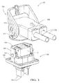
Fig. 1 is an exploded perspective view of a connector assembly according to one embodiment; -
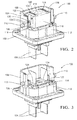
Fig. 2 is a perspective view of a first connector of the connector system ofFig. 1 having a terminal protection device (TPD) in a first position enclosing a terminal within the first connector held in the first position by a pair of retaining arms according to one embodiment; -
Fig. 3 is a perspective view of the first connector of the connector system ofFig. 1 having the TPD in a second position exposing the terminal according to one embodiment; -
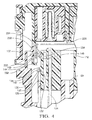
Fig. 4 is a cutaway perspective view of the connector system ofFig. 1 showing a release wedge and a first and second nib according to one embodiment; -
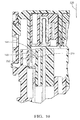
Fig. 5 is a cutaway perspective view of the connector system ofFig. 1 showing the release wedge spreading the retaining arms according to one embodiment; -
Fig. 6 is a cutaway perspective view of the connector system ofFig. 1 showing the engagement of the first nub with the second nib according to one embodiment; -
Fig. 7 is perspective view of the alignment of the a first connector with a second connector of the connector system ofFig. 1 prior to connection according to one embodiment; -
Fig. 8 is a cutaway perspective view showing an initial phase of connecting the first connector to the second connector of the connector system ofFig. 1 according to one embodiment; -
Fig. 9 is a cutaway perspective view showing the second nibs contacting the first nibs and causing the flexible beams to flex inwardly during the connection of the first connector to the second connector of the connector system ofFig. 1 according to one embodiment; -
Fig. 10 is a cutaway perspective view showing the engagement of the upper inclined surface with the lower inclined surface of the first nib thereby holding the first and second connectors together in a pre-staged condition during the connection of the first connector to the second connector of the connector system ofFig. 1 according to one embodiment; -
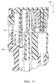
Fig. 11 is a cutaway perspective view showing the disengagement of the upper inclined surface from the lower inclined surface of the first nib during the connection of the first connector to the second connector of the connector system ofFig. 1 according to one embodiment; -
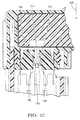
Fig. 12 is a cutaway perspective view showing the engagement of the release wedge with the retaining arms, allowing the first stop to pass between the retainingarms 126 during the connection of the first connector to the second connector of the connector system ofFig. 1 according to one embodiment; -
Fig. 13 is perspective view of the connector system ofFig. 1 showing cam posts of the first housing engaging the entrance of cam slots of the mating assist lever with the mating assist lever in the open position according to one embodiment; -
Fig. 14 is perspective view of the connector system ofFig. 1 showing the mating assist lever in the closed position according to one embodiment; -
Fig. 15 is a cutaway perspective view showing the disengagement of the HVIL shunt from the HVIL terminals during the disconnection of the first connector from the second connector of the connector system ofFig. 1 according to one embodiment; -
Fig. 16 is a cutaway perspective view showing the disengagement of the male blade terminals from the female socket terminals during the disconnection of the first connector from the second connector of the connector system ofFig. 1 according to one embodiment; -
Fig. 17 is a cutaway perspective view showing the engagement of the second stop with the closed end of the closed-end slot during the disconnection of the first connector from the second connector of the connector system ofFig. 1 according to one embodiment; -
Fig. 18 is a cutaway perspective view showing the engagement of the first and second nibs to hold the first and second connectors in the pre-staged position during the disconnection of the first connector from the second connector of the connector system ofFig. 1 according to one embodiment; -
Fig. 19 is a cutaway perspective view showing the flexing of the flexible beams inward during the disconnection of the first connector from the second connector of the connector system ofFig. 1 according to one embodiment; -
Fig. 20 is a cutaway perspective view showing the movement of the second nib past the first nib during the disconnection of the first connector from the second connector of the connector system ofFig. 1 according to one embodiment; and -
Fig. 21 is a perspective view of the second connector being removed from the first connector during the disconnection of the first connector from the second connector of the connector system ofFig. 1 according to one embodiment. - Presented herein is a connector system having a first connector and a second connector that each contains termination elements or "terminals" for wire electrical cables, fiber optic cables, pneumatic lines, hydraulic lines, etc. The housing of the first connector includes a moveable terminal protection device (TPD). The TPD moves from a first position wherein the terminals in the first connector are protected by the TPD to a second position where a portion of the terminals protrude through the TPD when the first connector is connected to the second connector. The TPD is held in the first position until released by the second connector during the connection of the first connector with the second connector. When the first and second connectors are disconnected, the second connector pulls the TPD from the second position back to the first position, thus reestablishing protection of the terminals.
-
Fig 1 illustrates a non-limiting example of aconnector system 10, in this particular example an electrical connector system for high voltage applications, i.e. greater than 48 volts.. The connector assembly includes afirst connector 100 having afirst housing 102 containing a pair ofmale blade terminals 104 terminating a pair of wire electrical cables or conductive bus bars (not shown). Thefirst connector 100 is based around thefirst housing 102 to which the other components of thefirst connector 100 are attached. Thefirst housing 102 is formed of a dielectric material, such as polybutylene terephthalate (PBT), polypropylene (PP), or polyamide (PA, commonly known as NYLON). Thefirst housing 102 defines aU-shaped shroud 106 around themale blade terminals 104. Theside walls 108 of the shroud define cam posts 110. - The
connector system 10 further includes asecond connector 200 having asecond housing 202 containing a pair or correspondingfemale socket terminals 206 terminating a pair of wireelectrical cables 208 that are configured to mate with themale blade terminals 104. Thesecond connector 200 include amating assist lever 210 rotatably attached to thesecond housing 202. Themating assist lever 210 defines acurved cam slot 212 that is configured to accept the post defined by thefirst housing 102. Thecam post 110 and thecam slot 212 cooperate to generate a force effective to connect and disconnect the first andsecond connectors lever 210 is rotated. Thesecond housing 202 and the mating assistlever 210 are formed of a dielectric material such as PBT, PP, or NYLON. - An
intermediate housing 112 configured to protect themale blade terminals 104 from inadvertent contact by an operator when thefirst connector 100 is disconnected from thesecond connector 200, hereinafter referred to as a terminal protection device 112 (TPD), is slideably attached to thefirst housing 102. TheTPD 112 is formed of a dielectric material such as PBT, PP, or NYLON. TheTPD 112 has a generally open rectangular box shape having atop wall 114, twomajor side walls 116 and twominor side walls 118. TheTPD 112 is configured to move from afirst position 120 wherein themale blade terminals 104 are enclosed within theTPD 112 as shown inFig. 2 to asecond position 122 wherein a portion of themale blade terminals 104 protrudes through a pair ofapertures 124 defined in thetop wall 114 of theTPD 112 as shown inFig. 3 . TheTPD 112 is configured to enclose themale blade terminals 104 when theTPD 112 is in thefirst position 120, thus preventing accidental contact by a finger of an assembly operator or a foreign conductive element, such as a screwdriver or wrench, with themale blade terminals 104 when thefirst connector 100 is not mated with thesecond connector 200. - As best shown in
Fig. 2 , theTPD 112 is held in thefirst position 120 by 2 pairs of flexible retainingarms 126 projecting from thefirst housing 102, one pair of retainingarms 126 are located next to each of theminor side walls 118 of theTPD 112. The retainingarms 126 of each pair are separated by agap 128. The free ends 130 of each of the pair of retainingarms 126 define a substantiallyflat portion 132 on a mesial portion of thetop surface 134 of the retainingarms 126 adjacent theminor side walls 118 of theTPD 112. Each of theminor side walls 118 of theTPD 112 define afirst stop 136 having a substantially flatbottom surface 138 configured to engage theflat portions 132 on thetop surfaces 134 of the retainingarms 126 and span thegap 128 between the retainingarms 126. A distal portion of thetop surface 134 of the retainingarms 126 defines anangled portion 140 running from thetop surface 134 of the retainingarms 126 and toward thegap 128 between the retainingarms 126. - As illustrated in
Fig. 4 , thesecond housing 202 defines a pair ofrelease wedges 214 positioned to align with theangled portions 140 when thefirst connector 100 is connected to thesecond connector 200. Thebottom portion 216 of therelease wedge 214 defines a pair ofangled surfaces 218 having a greater width than theangled portions 140 of the retainingarms 126. - As shown in
Fig. 5 , as thesecond connector 200 is moved in aconnection direction 220 relative to thefirst connector 100, therelease wedge 214 engages theangled portions 140 of the retainingarms 126, flexing the two retainingarms 126 apart until thegap 128 between the retainingarms 126 is greater than the width of thefirst stop 136, allowing thefirst stop 136 to pass between the retainingarms 126. TheTPD 112 is pushed from thefirst position 120 to thesecond position 122 by the contact with thesecond housing 202 as thefirst connector 100 is mated with thesecond connector 200. - As illustrated in
Fig. 6 , theTPD 112 further includes a plurality offlexible beams 142 defined in the minor sides, each having afirst nib 144 projecting therefrom. Thesecond connector 200 also includes plurality ofsecond nibs 222 projecting therefrom. Thelower surfaces 146 of thefirst nibs 144 are configured to engage theupper surfaces 224 of thesecond nibs 222 as thefirst connector 100 is disconnected from thesecond connector 200, thereby pulling theTPD 112 from thesecond position 122 back to thefirst position 120 as the first andsecond connectors disconnection direction 226. TheTPD 112 defines a pair ofsecond stops 148 having a substantially flatupper surface 150 in themajor side walls 116 of theTPD 112 that are disposed within a pair ofclosed end slots 152 defined by thefirst housing 102. Theupper surfaces 150 of thesecond stops 148 are configured to engage the closed ends 154 of theclosed end slots 152 as theTPD 112 reaches thefirst position 120, thereby inhibiting the removal of theTPD 112 from thefirst housing 102 and cooperating with the retainingarms 126 to retain theTPD 112 in thefirst position 120. As can best be seen inFig. 2 , theupper surface 156 of thefirst stop 136 is rounded to flex the retainingarms 126 apart so that thefirst stop 136 can pass through thegap 128 between the retainingarms 126 as theTPD 112 moves from thesecond position 122 back to thefirst position 120. Theupper surface 228 of therelease wedge 214 is also rounded to help flex and spread the retainingarms 126 apart when theTPD 112 moves from thesecond position 122 back to thefirst position 120. - As shown in
Fig 4 , thesecond connector 200 includes acompliant seal 230 surrounding thesecond housing 202 that is configured to contact a perimeter of thefirst housing 102, thereby protecting the male andfemale terminals seal retainer 232 designed to hold theseal 230 in place on thesecond housing 202 defines thesecond nibs 222. - The upper and
lower surface first nib 144 defines an inclined surface as does the upper andlower surfaces second nib 222. A value of a first angle formed between the inclinedupper surface 158 of thefirst nib 144 and a longitudinal axis X of themale blade terminal 104 is less than a value of a second angle formed between the lowerinclined surface 146 of thefirst nib 144 and the longitudinal axis X. A value of a third angle formed between the upperinclined surface 224 of thesecond nib 222 and the longitudinal axis X is greater than a value of a fourth angle formed between the lowerinclined surface 234 of thesecond nib 222 and the longitudinal axis X. Therefore, a first force F1 in theconnection direction 220 required to flex theflexible beam 142 so that thesecond nib 222 may move past thefirst nib 144 as the lowerinclined surface 234 of thesecond nib 222 engages the upperinclined surface 158 of thefirst nib 144 as thefirst connector 100 is connected to thesecond connector 200 is less than a second force F2 in thedisconnection direction 226 required to flex theflexible beam 142 so that thesecond nib 222 may move past thefirst nib 144 as the upperinclined surface 224 of thesecond nib 222 engages the lowerinclined surface 146 of thefirst nib 144 as thefirst connector 100 is disconnected from thesecond connector 200. The second force F2 is greater than frictional forces exerted on theTPD 112 by thefirst housing 102 and themale blade terminals 104 to maintain engagement of the upperinclined surface 224 of thesecond nib 222 with the lowerinclined surface 146 of thefirst nib 144 as thefirst connector 100 is disconnected from thesecond connector 200. Theinclined surfaces - The engagement of the
first nib 144 with thesecond nib 222 connects thefirst connector 100 to thesecond connector 200 in a pre-staged position. This feature holds the first andsecond connectors lever 210 can be rotated to fully mate thefirst connector 100 with thesecond connector 200. - The second conductor also includes a high voltage interlock (HVIL)
shunt 236 that is designed to connect a pair ofmating HVIL terminals 160 in thefirst connector 100 when the first andsecond connectors HVIL terminals 160 are linked to a control circuit (not shown) that inhibits themale blade terminals 104 in thefirst connector 100 from being energized until theHVIL terminals 160 are shorted by theHVIL shunt 236. The blades of theHVIL shunt 236 are shorter than themale blade terminals 104, ensuring that the female and male terminals in the first andsecond connectors HVIL shunt 236 interconnects theHVIL terminals 160, thus triggering the HVIL circuit to energize themale blade terminals 104. - The
TPD 112 also encloses theHVIL terminals 160 when theTPD 112 is in thefirst position 120, thus preventing accidental contact by a foreign conductive element with theHVIL terminals 160 that could form a short circuit between theHVIL terminals 160 and inappropriately enable the HVIL circuit. When theTPD 112 is moved to thesecond position 122, theHVIL terminals 160 are exposed allowing contact with theHVIL shunt 236 in thesecond connector 200. - The process of connecting and disconnecting the first and
second connectors second connectors second connector 200 is aligned with thefirst connector 100 with the mating assistlever 210 in the open position 238 (seeFig. 7 ). As thesecond housing 202 of thesecond connector 200 is pushed onto thefirst housing 102 of the first connector 100 (seeFig. 8 ), thesecond nibs 222 contacts thefirst nibs 144 causing theflexible beams 142 to flex inwardly (seeFig. 9 ), thus allowing thesecond nib 222 to move past thefirst nib 144 so that the upperinclined surface 224 of thesecond nib 222 engages the lowerinclined surface 146 of the first nib 144 (seeFig. 10 ) and thereby holding the first andsecond connectors second housing 202 is further pushed onto thefirst housing 102, the upperinclined surface 224 of thesecond nib 222 is no longer engaged with the lowerinclined surface 146 of the first nib 144 (seeFig. 11 ). Therelease wedge 214 engages and spreads the retainingarms 126, allowing thefirst stop 136 to pass between the retaining arms 126 (seeFig. 12 ) and allowing theTPD 112 to move from thefirst position 120 toward thesecond position 122. Thesecond housing 202 is pushed onto thefirst housing 102 until the cam posts 110 of thefirst housing 102 engage the entrance of thecam slots 212 of the mating assist lever 210 (seeFig. 13 ). - The
mating assist lever 210 is then moved from the open position 238 (seeFig. 13 ) to the closed position 240 (seeFig. 14 ). As the mating assistlever 210 is rotated, the cam posts 110 andcam slots 212 push thefirst housing 102 further onto thesecond housing 202. Thesecond housing 202 contacts theTPD 112 pushing it further toward thesecond position 122 and exposing themale blade terminals 104. As the mating assistlever 210 reaches theclosed position 240, themale blade terminals 104 are received in thefemale socket terminals 206, theHVIL shunt 236 is received in theHVIL terminals 160 and theTPD 112 is pushed into thesecond position 122. - To begin the process of disconnecting the first and
second connectors lever 210 is rotated from the closed position 240 (seeFig. 14 ) to the open position 238 (seeFig. 13 ). As the mating assistlever 210 is rotated, the cam posts 110 andcam slots 212 pull the first and second housings apart, first disengaging theHVIL shunt 236 from the HVIL terminals 160 (seeFig. 15 ) and then themale blade terminals 104 from the female socket terminals 206 (seeFig. 16 ). The upperinclined surface 224 of thesecond nib 222 engages the lowerinclined surface 146 of thefirst nib 144 pulling theTPD 112 from thesecond position 122 back toward the first position 120 (seeFig. 16 ). The roundedupper surfaces release wedge 214 and thefirst stop 136 contact the retainingarms 126 and spread the retainingarms 126 apart, allowing theTPD 112 to return to thefirst position 120. As the mating assistlever 210 returns to theopen position 238, thesecond stop 148 engages theclosed end 154 of theclosed end slot 152, thus securing theTPD 112 in the first position 120 (seeFig. 17 ). The first andsecond nibs 222 will hold the first andsecond connectors Fig. 18 ) until a disconnecting force is applied to flex theflexible beams 142 inward (seeFig. 19 ) allowing thesecond nib 222 to move past the first nib 144 (seeFig. 20 ) and thesecond connector 200 to be removed from the first connector 100 (seeFig. 21 ). - Accordingly, a
connector system 10 is provided. The connector assembly includes a terminal protection device 112 (TPD) that provides the benefit of covering themale blade terminals 104 andHVIL terminals 160 when thefirst connector 100 is not connected to thesecond connector 200, thus reducing the possibility of inadvertent contact of themale blade terminals 104 orHVIL terminals 160 by the hand of an operator or a conductive element, e.g. a tool. The connector assembly also includes interlocking first andsecond nibs second connectors lever 210 while the mating assistlever 210 is in an opened position. The first andsecond nibs second connectors - While the
connector system 10 illustrated herein is characterized as a right angle (ninety degree) connector assembly with amating assist lever 210, features of this invention may also be applied to a straight (one hundred eighty degree) connector assembly. The features of this invention may also be applied to a connector assembly that does not include amating assist lever 210. Theintermediate housing 112 described herein is configured to prevent inadvertent contact with an exposed electrical terminal. Other embodiments of the invention may be envisioned wherein theintermediate housing 112 functions as a terminal position assurance (TPA) device configured to stabilize the male terminals until mated with the corresponding female terminals. - The examples presented herein are directed to electrical connector assemblies, however other embodiments of the connector assembly may be envisioned that are adapted for use with optical cables or hybrid connectors including both electrical and optical cable connections. Yet other embodiments of the
connector system 10 may be envisioned that are configured to interconnect pneumatic or hydraulic lines. - Although the illustrated embodiment of the connector assembly shown herein includes an
HVIL shunt 236 andHVIL terminals 160, other embodiments of the connector assembly may be envisioned without those elements in applications of the connector assembly where a high voltage interlock circuit is not required. - While this invention has been described in terms of the preferred embodiments thereof, it is not intended to be so limited, but rather only to the extent set forth in the claims that follow. Moreover, the use of the terms first, second, etc. does not denote any order of importance, but rather the terms first, second, etc. are used to distinguish one element from another. Furthermore, the use of the terms a, an, etc. do not denote a limitation of quantity, but rather denote the presence of at least one of the referenced items.
Claims (10)
- Connector assembly (10), comprising:a first connector (100) having a first housing (102) and an intermediate housing (112) slideably attached to the first housing (102), said intermediate housing (112) is configured to move from a first position (120) to a second position (122), wherein a flexible retaining arm projecting from the first housing (102) is configured to releasably hold the intermediate housing (112) in the first position (120); anda second connector (200) having a second housing (202) configured to mate with the first housing (102), wherein the second housing (202) defines a release wedge (214) configured to engage and flex the retaining arm, thereby releasing the intermediate housing (112) from engagement with the retaining arm and allowing the intermediate housing (112) to move from the first position (120) to the second position (122) as the first connector (100) is connected to the second connector (200).
- Connector assembly (10) according to claim 1, wherein the first housing (102) defines a pair of said retaining arms (126) configured to flex laterally away from one another allowing a first stop (136) defined by the intermediate housing (112) to pass between them when the release wedge (214) flexes the pair of retaining arms (126).
- Connector assembly (10) according to claim 2, wherein free ends (130) of the pair of retaining arms (126) define a flat portion (132) configured to engage the first stop (136) and wherein the free ends (130) of the pair of retaining arms (126) define an angled portion (140) configured to engage the release wedge (214).
- Connector assembly (10) according to any of the preceding claims, wherein the first housing (102) defines a closed end slot (152) and the intermediate housing (112) defines a second stop (148) disposed within the closed end slot (152) and configured to retain the intermediate housing (112) in the first position (120) when the first connector (100) is disconnected from the second connector (200).
- Connector assembly (10) according to any of the preceding claims, wherein the intermediate housing (112) includes a flexible beam (142) having a first nib (144) projecting therefrom, said first nib (144) defining a first lower inclined surface (146), wherein the second connector (200) includes a second nib (222) projecting therefrom, said second nib (222) defining a first upper inclined surface (158), and wherein the first lower inclined surface (146) of the first nib (144) is configured to engage the first upper inclined surface (158) of the second nib (222) as the first connector (100) is disconnected from the second connector (200), thereby moving the intermediate housing (112) from the second position (122) to the first position (120).
- Connector assembly (10) according to claim 5, wherein the engagement of the first lower inclined surface (146) of the first nib (144) with the first upper inclined surface (158) of the second nib (222) connects the first connector (100) to the second connector (200) in a pre-staged condition.
- Connector assembly (10) according to claim 5 or 6, wherein the first nib (144) further defines a second upper inclined surface (158) and the second nib (222) further defines a second lower inclined surface (146), wherein a value of a first angle formed between the second upper inclined surface (158) of the first nib (144) and a longitudinal axis of the first housing (102) is less than a value of a second angle formed between the first lower inclined surface (146) of the first nib (144) and the longitudinal axis and wherein a value of a third angle formed between the first upper inclined surface (158) of the second nib (222) and the longitudinal axis is greater than a value of a fourth angle formed between the second lower inclined surface (146) of the second nib (222) and the longitudinal axis.
- Connector assembly (10) according to any of the claims 5-7, wherein a first force required to move the second nib (222) past the first nib (144) when the first connector (100) is connected to the second connector (200) is less than a second force required to move the second nib (222) past the first nib (144) when the first connector (100) is disconnected from the second connector (200).
- Connector assembly (10) according to any of the preceding claims, wherein the first housing (102) contains a first electrical terminal and the second housing (202) contains a corresponding second electrical terminal configured to mate with the first electrical terminal, wherein the first electrical terminal is enclosed within the intermediate housing (112) in the first position (120), and wherein at least a portion of the first electrical terminal protrudes from an aperture in a surface of the intermediate housing (112) in the second position (122).
- Connector assembly (10) according to any of the preceding claims, wherein the second connector (200) includes a mating assist lever (210) rotatably attached to the second housing (202), said mating assist lever (210) defining a curved slot configured to accept a post defined by the first housing (102) and wherein the post and the curved slot cooperate to generate a force effective to connect and disconnect the first and second connectors (100, 200) as the mating assist lever (210) is rotated.
Applications Claiming Priority (1)
| Application Number | Priority Date | Filing Date | Title |
|---|---|---|---|
| US14/851,223 US9608357B1 (en) | 2015-09-11 | 2015-09-11 | Right angle connector with terminal contact protection |
Publications (1)
| Publication Number | Publication Date |
|---|---|
| EP3142194A1 true EP3142194A1 (en) | 2017-03-15 |
Family
ID=56883730
Family Applications (1)
| Application Number | Title | Priority Date | Filing Date |
|---|---|---|---|
| EP16187683.4A Withdrawn EP3142194A1 (en) | 2015-09-11 | 2016-09-07 | Right angle connector with terminal contact protection |
Country Status (4)
| Country | Link |
|---|---|
| US (1) | US9608357B1 (en) |
| EP (1) | EP3142194A1 (en) |
| KR (1) | KR102556351B1 (en) |
| CN (1) | CN106532332B (en) |
Cited By (1)
| Publication number | Priority date | Publication date | Assignee | Title |
|---|---|---|---|---|
| EP3657610A1 (en) * | 2018-10-30 | 2020-05-27 | Aptiv Technologies Limited | Electrical connector with high vibration resistant locks |
Families Citing this family (28)
| Publication number | Priority date | Publication date | Assignee | Title |
|---|---|---|---|---|
| DE102017003296B3 (en) * | 2017-04-04 | 2018-05-30 | Te Connectivity Germany Gmbh | Connector and method for making a connector |
| US10116078B1 (en) * | 2017-08-01 | 2018-10-30 | Delphi Technologies, Inc. | High current compression blade connection system |
| US10355389B2 (en) * | 2017-08-01 | 2019-07-16 | Delphi Technologies, Llc | High-current electrical terminal |
| JP6680278B2 (en) * | 2017-08-29 | 2020-04-15 | 株式会社オートネットワーク技術研究所 | Connector device and male connector |
| US10218116B1 (en) * | 2017-10-03 | 2019-02-26 | Ford Global Technologies, Llc | Locking vehicle electrical connector |
| US10079446B1 (en) * | 2017-11-20 | 2018-09-18 | Delphi Technologies, Inc. | Electrical connector with cam actuated terminal lock |
| US20190260150A1 (en) * | 2018-02-19 | 2019-08-22 | Te Connectivity Corporation | Electrical power connector assembly |
| EP3544125B1 (en) * | 2018-03-19 | 2022-12-07 | Tyco Electronics AMP Korea Co., Ltd. | Connector assembly comprising a male connector |
| JP6922838B2 (en) * | 2018-05-16 | 2021-08-18 | 住友電装株式会社 | connector |
| JP7021150B2 (en) * | 2019-05-27 | 2022-02-16 | 矢崎総業株式会社 | How to assemble the lever type connector and the lever type connector |
| JP7303985B2 (en) * | 2019-12-02 | 2023-07-06 | 株式会社オートネットワーク技術研究所 | connector |
| US10971856B1 (en) * | 2020-01-30 | 2021-04-06 | Aptiv Technologies Limited | Lever-type electrical connector |
| JP7437614B2 (en) * | 2020-08-26 | 2024-02-26 | 住友電装株式会社 | connector |
| DE102021005717B4 (en) * | 2020-11-30 | 2026-01-29 | Sumitomo Wiring Systems, Ltd. | First connector and connector arrangement |
| JP7447857B2 (en) * | 2021-03-31 | 2024-03-12 | 住友電装株式会社 | Connectors and wire harnesses |
| JP7533317B2 (en) * | 2021-03-31 | 2024-08-14 | 住友電装株式会社 | First connector, second connector, and connector assembly |
| US11552426B1 (en) | 2021-06-18 | 2023-01-10 | Aptiv Technologies Limited | Sealed electrical connector having a male blade stabilizer with a seal retention feature |
| USD1066253S1 (en) * | 2022-02-14 | 2025-03-11 | Techtronic Cordless Gp | Harness plug |
| US20230327374A1 (en) * | 2022-04-06 | 2023-10-12 | Aptiv Technologies Limited | Vibration resistant connector system with mating assistance feature |
| EP4274033B1 (en) | 2022-05-06 | 2025-02-26 | Aptiv Technologies AG | Electrical power connector assembly |
| CN117096648A (en) * | 2022-05-14 | 2023-11-21 | 富士康(昆山)电脑接插件有限公司 | Electric connector |
| JP1730749S (en) * | 2022-05-20 | 2022-11-28 | connector | |
| JP1730748S (en) * | 2022-05-20 | 2022-11-28 | connector | |
| CN217882141U (en) * | 2022-06-08 | 2022-11-22 | 东莞富强电子有限公司 | Electric connector set |
| JP1788221S (en) * | 2024-07-17 | 2025-01-06 | connector | |
| JP1788223S (en) * | 2024-07-17 | 2025-01-06 | connector | |
| JP1788222S (en) * | 2024-07-17 | 2025-01-06 | connector | |
| WO2026029075A1 (en) * | 2024-07-30 | 2026-02-05 | 古河電気工業株式会社 | Harness-side connector and connector connection structure |
Citations (3)
| Publication number | Priority date | Publication date | Assignee | Title |
|---|---|---|---|---|
| US5437558A (en) * | 1993-02-01 | 1995-08-01 | Fujitsu Limited | Connector having skirt with holes to receive plug pins and alignment pin |
| DE19952023A1 (en) * | 1999-10-28 | 2001-05-31 | Grote & Hartmann | Plug connector coupling has protector with contact element throughways for insertion into housing part, latched at distance from floor, moved towards floor after unlatching during coupling |
| EP1672747A1 (en) * | 2004-12-14 | 2006-06-21 | Sumitomo Wiring Systems, Ltd. | A connector |
Family Cites Families (6)
| Publication number | Priority date | Publication date | Assignee | Title |
|---|---|---|---|---|
| US6821135B1 (en) * | 2003-08-06 | 2004-11-23 | Tyco Electronics Corporation | Alignment plate for aligning connector terminals |
| JP2006031965A (en) * | 2004-07-12 | 2006-02-02 | Yazaki Corp | Connector lock structure |
| JP2009301856A (en) * | 2008-06-12 | 2009-12-24 | Hitachi Cable Ltd | Connector |
| JP5018740B2 (en) * | 2008-11-10 | 2012-09-05 | 日立電線株式会社 | connector |
| JP5293627B2 (en) * | 2010-02-01 | 2013-09-18 | 日立電線株式会社 | connector |
| WO2013046671A1 (en) * | 2011-09-27 | 2013-04-04 | Yazaki Corporation | Shielded connector |
-
2015
- 2015-09-11 US US14/851,223 patent/US9608357B1/en active Active
-
2016
- 2016-09-07 EP EP16187683.4A patent/EP3142194A1/en not_active Withdrawn
- 2016-09-07 KR KR1020160114734A patent/KR102556351B1/en active Active
- 2016-09-09 CN CN201610814611.9A patent/CN106532332B/en active Active
Patent Citations (3)
| Publication number | Priority date | Publication date | Assignee | Title |
|---|---|---|---|---|
| US5437558A (en) * | 1993-02-01 | 1995-08-01 | Fujitsu Limited | Connector having skirt with holes to receive plug pins and alignment pin |
| DE19952023A1 (en) * | 1999-10-28 | 2001-05-31 | Grote & Hartmann | Plug connector coupling has protector with contact element throughways for insertion into housing part, latched at distance from floor, moved towards floor after unlatching during coupling |
| EP1672747A1 (en) * | 2004-12-14 | 2006-06-21 | Sumitomo Wiring Systems, Ltd. | A connector |
Cited By (1)
| Publication number | Priority date | Publication date | Assignee | Title |
|---|---|---|---|---|
| EP3657610A1 (en) * | 2018-10-30 | 2020-05-27 | Aptiv Technologies Limited | Electrical connector with high vibration resistant locks |
Also Published As
| Publication number | Publication date |
|---|---|
| KR102556351B1 (en) | 2023-07-18 |
| KR20170031621A (en) | 2017-03-21 |
| US9608357B1 (en) | 2017-03-28 |
| US20170077639A1 (en) | 2017-03-16 |
| CN106532332A (en) | 2017-03-22 |
| CN106532332B (en) | 2020-11-10 |
Similar Documents
| Publication | Publication Date | Title |
|---|---|---|
| US9608357B1 (en) | Right angle connector with terminal contact protection | |
| US9455523B1 (en) | Right angle connection assembly | |
| KR101973894B1 (en) | Electrical connector with a terminal position assurance device | |
| EP2975698B1 (en) | Electrical connector with a terminal position assurance device | |
| EP3769375B1 (en) | Connector position assurance member | |
| US5993255A (en) | Electrical connector with combination terminal guide and terminal position assurance member | |
| EP2830162A1 (en) | Electrical connector keying system | |
| EP3171459A1 (en) | Electrical connector with a terminal position assurance device | |
| JP2015023034A (en) | Quick connect power connector | |
| CN110571567B (en) | Staged release electrical connector assembly | |
| EP2790273A1 (en) | Electrical connector system connectable in a straight or right angle configuration | |
| CN109428203B (en) | Connector device and male connector | |
| US8241052B2 (en) | Electrical connector system with power and command connectors | |
| US9705228B2 (en) | Connector system with disconnection evident connector position assurance feature | |
| US9929508B2 (en) | Electrical connector | |
| EP3769377B1 (en) | Connector position assurance member | |
| CN113826287B (en) | Plug-in connector part capable of being separated safely | |
| JP7460397B2 (en) | High voltage electrical connector with CPA assembled on slider | |
| US20070059973A1 (en) | Hot plug wire contact and connector assembly | |
| US10320123B1 (en) | Right angle connector with terminal contact protection | |
| KR102481782B1 (en) | High voltage connector | |
| JP7408279B2 (en) | power distribution assembly | |
| EP3300179B1 (en) | Electrical connector with male blade stabilizer | |
| JP7575437B2 (en) | connector | |
| EP4485708A1 (en) | Electrical power connector with locking cpa and method for using it in a connection |
Legal Events
| Date | Code | Title | Description |
|---|---|---|---|
| PUAI | Public reference made under article 153(3) epc to a published international application that has entered the european phase |
Free format text: ORIGINAL CODE: 0009012 |
|
| AK | Designated contracting states |
Kind code of ref document: A1 Designated state(s): AL AT BE BG CH CY CZ DE DK EE ES FI FR GB GR HR HU IE IS IT LI LT LU LV MC MK MT NL NO PL PT RO RS SE SI SK SM TR |
|
| AX | Request for extension of the european patent |
Extension state: BA ME |
|
| STAA | Information on the status of an ep patent application or granted ep patent |
Free format text: STATUS: THE APPLICATION IS DEEMED TO BE WITHDRAWN |
|
| 18D | Application deemed to be withdrawn |
Effective date: 20170916 |