EP3142135A1 - Input device - Google Patents
Input device Download PDFInfo
- Publication number
- EP3142135A1 EP3142135A1 EP16182571.6A EP16182571A EP3142135A1 EP 3142135 A1 EP3142135 A1 EP 3142135A1 EP 16182571 A EP16182571 A EP 16182571A EP 3142135 A1 EP3142135 A1 EP 3142135A1
- Authority
- EP
- European Patent Office
- Prior art keywords
- sleeve
- gap
- input device
- rotation axis
- holding
- Prior art date
- Legal status (The legal status is an assumption and is not a legal conclusion. Google has not performed a legal analysis and makes no representation as to the accuracy of the status listed.)
- Granted
Links
Images






Classifications
-
- H—ELECTRICITY
- H01—ELECTRIC ELEMENTS
- H01H—ELECTRIC SWITCHES; RELAYS; SELECTORS; EMERGENCY PROTECTIVE DEVICES
- H01H19/00—Switches operated by an operating part which is rotatable about a longitudinal axis thereof and which is acted upon directly by a solid body external to the switch, e.g. by a hand
- H01H19/54—Switches operated by an operating part which is rotatable about a longitudinal axis thereof and which is acted upon directly by a solid body external to the switch, e.g. by a hand the operating part having at least five or an unspecified number of operative positions
- H01H19/56—Angularly-movable actuating part carrying contacts, e.g. drum switch
- H01H19/58—Angularly-movable actuating part carrying contacts, e.g. drum switch having only axial contact pressure, e.g. disc switch, wafer switch
- H01H19/585—Angularly-movable actuating part carrying contacts, e.g. drum switch having only axial contact pressure, e.g. disc switch, wafer switch provided with printed circuit contacts
-
- F—MECHANICAL ENGINEERING; LIGHTING; HEATING; WEAPONS; BLASTING
- F16—ENGINEERING ELEMENTS AND UNITS; GENERAL MEASURES FOR PRODUCING AND MAINTAINING EFFECTIVE FUNCTIONING OF MACHINES OR INSTALLATIONS; THERMAL INSULATION IN GENERAL
- F16F—SPRINGS; SHOCK-ABSORBERS; MEANS FOR DAMPING VIBRATION
- F16F9/00—Springs, vibration-dampers, shock-absorbers, or similarly-constructed movement-dampers using a fluid or the equivalent as damping medium
- F16F9/32—Details
- F16F9/53—Means for adjusting damping characteristics by varying fluid viscosity, e.g. electromagnetically
-
- F—MECHANICAL ENGINEERING; LIGHTING; HEATING; WEAPONS; BLASTING
- F16—ENGINEERING ELEMENTS AND UNITS; GENERAL MEASURES FOR PRODUCING AND MAINTAINING EFFECTIVE FUNCTIONING OF MACHINES OR INSTALLATIONS; THERMAL INSULATION IN GENERAL
- F16F—SPRINGS; SHOCK-ABSORBERS; MEANS FOR DAMPING VIBRATION
- F16F2224/00—Materials; Material properties
- F16F2224/04—Fluids
-
- H—ELECTRICITY
- H01—ELECTRIC ELEMENTS
- H01H—ELECTRIC SWITCHES; RELAYS; SELECTORS; EMERGENCY PROTECTIVE DEVICES
- H01H19/00—Switches operated by an operating part which is rotatable about a longitudinal axis thereof and which is acted upon directly by a solid body external to the switch, e.g. by a hand
- H01H19/02—Details
- H01H19/10—Movable parts; Contacts mounted thereon
- H01H19/11—Movable parts; Contacts mounted thereon with indexing means
-
- H—ELECTRICITY
- H01—ELECTRIC ELEMENTS
- H01H—ELECTRIC SWITCHES; RELAYS; SELECTORS; EMERGENCY PROTECTIVE DEVICES
- H01H19/00—Switches operated by an operating part which is rotatable about a longitudinal axis thereof and which is acted upon directly by a solid body external to the switch, e.g. by a hand
- H01H19/02—Details
- H01H19/10—Movable parts; Contacts mounted thereon
- H01H19/20—Driving mechanisms allowing angular displacement of the operating part to be effective in either direction
Definitions
- the present invention relates to an input device.
- Japanese Unexamined Patent Application Publication No. 2007-201415 discloses an input device in which input is performed according to a relative rotation between a plurality of members.
- a cam for allowing a user to feel a resistance force referred to as a click feeling according to rotation is provided.
- the present invention provides an input device by which a resistance force generated according to a relative rotation between members can be changed.
- an input device which includes a first member and a second member and which is configured to perform input according to a relative rotation between the first member and the second member, including: a bearing portion configured to rotatably support the first member and the second member; a gap which is formed between the first member and the second member at a position different from that of the bearing portion; and a viscous material which is present in the gap and is in contact with the first member and the second member.
- a distance between the first member and the second member in the gap may be greater than a distance between the first member and the second member in the bearing portion.
- one of the first member and the second member may include a sleeve and a sleeve holding portion configured to hold the sleeve, and the other of the first member and the second member, and the sleeve may form the gap.
- the structure of the gap can be changed by replacing the sleeve, it is possible to manufacture a plurality of kinds of input device having resistance forces different from each other while using a common structure.
- the input device of the present invention further includes a resistance generation portion configured to generate a resistance force according to a relative rotation angle between the first member and the second member, in which the viscous material may be in contact with the first member and the second member at a position different from that of the resistance generation portion.
- a resistance generation portion configured to generate a resistance force according to a relative rotation angle between the first member and the second member, in which the viscous material may be in contact with the first member and the second member at a position different from that of the resistance generation portion.
- the other member may include a cylindrical gap formation outer surface
- the sleeve holding portion may include a cylindrical holding inner surface which is positioned outside the gap formation outer surface
- the sleeve may include a cylindrical holding outer surface which is in contact with the inner portion of the holding inner surface and a cylindrical gap formation inner surface which is positioned outside the gap formation outer surface, and the gap may be formed between the gap formation outer surface and the gap formation inner surface.
- the sleeve since the sleeve has an approximately cylindrical shape, it is possible to simply change an extendable region of the gap between the gap formation outer length of the sleeve.
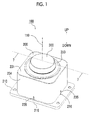
- the input device 100 includes a fixed member 200 and a rotary member 300 which can rotate in both directions relative to each other about a rotation axis 110 along a vertical direction, and includes a viscous material 400 described below with reference to Fig. 8 .
- the fixed member 200 of the present embodiment is fixed to a vehicle, and the rotary member 300 is operated by fingers of a user who performs input.
- the input based on rotation is transmitted to the outside as electric signals by a wire (not shown).
- the vertical direction is defined for convenience of descriptions, and does not define a direction in an actual use.
- a direction which passes the rotation axis 110 so as to be orthogonal to the rotation axis 110 is referred to as a radial direction.
- a radially outward direction is referred to as a direction away from the rotation axis 110, and a radially inward direction is referred to as a direction toward the rotation axis 110.
- a shape used in the following description does not strictly limit each component to a geometric shape, and is suggested so as to exemplify a schematic shape as an example which realizes a technical idea of the present embodiment.
- the fixed member 200 includes a base portion 210, a partition plate 220, a cover 230, a sleeve 240, and screws 250.
- the components of the fixed member 200 are fixed to each other such that the components do not rotate to each other around the rotation axis 110.
- the base portion 210 includes a seat portion 211, a first bearing portion 212, a cam portion 214, a first wall portion, 215, outer ribs 216, upper ribs 217, and lower bosses 218.
- the seat portion 211 extends in a plate shape along a plane orthogonal to the rotation axis 110.
- the first bearing portion 212 protrudes approximately cylindrically upward from the upper surface of the seat portion 211 along the rotation axis 110.
- a first bearing surface 213 which is a cylindrical outer surface of the first bearing portion 212 extends along the rotation axis 110 with the rotation axis 110 as a center.
- a hole which penetrates the first bearing portion 212 and the seat portion 211 in the vertical direction is provided at the center of the first bearing portion 212.
- the cam portion 214 extends in a plate shape upward from the seat portion 211.
- the cam portion 214 surrounds the first bearing portion 212 from the outside in the radial direction. Distances between the cam portion 214 and the outer surface of the first bearing portion 212 are different from each other according to the angle position around the rotation axis 110.
- the first wall portion 215 extends upward from the seat portion 211 so as to surround the cam portion 214 from the outside in the radial direction. When the first wall portion 215 is viewed from the top toward the bottom, the first wall portion 215 has an approximately rectangular shape.
- the outer ribs 216 extends upward to a lower position than the uppermost portion of the first wall portion 215 from the seat portion 211 along the outer surface of the first wall portion 215. When the outer ribs 216 are viewed from the top toward the bottom, each of the outer ribs 216 protrudes toward the outside in the radial direction from the outer surface of the first wall portion 215 in the vicinity of the center of each of four sides of the first wall portion 215 having an approximately rectangular shape.
- the upper ribs 217 extend upward from the upper edge of the first wall portion 215. When the upper ribs 217 are viewed from the top toward the bottom, each of the upper ribs 217 is positioned in the vicinity of the center of each of the four sides of the first wall portion 215 having an approximately rectangular shape.
- Four lower bosses 218 are provided so as to be close to corners of the first wall portion 215 having an approximately rectangular shape between the cam portion 214 and the first wall portion 215.
- Each of the four lower bosses 218 protrudes upward from the seat portion 211.
- a screw hole which penetrates each of the lower bosses 218 and the seat portion 211 is provided at the center of each lower boss 218.
- the partition plate 220 includes a plate-shaped member 221 having an approximately rectangular shape and fixed terminals 222.
- a circular center hole 223 having a center which coincides with the rotation axis 110 is provided in the plate-shaped member 221.
- the center hole 223 penetrates the plate-shaped member 221 vertically.
- a notch 224 which is recessed toward the inside in the radial direction is provided in the vicinity of the center of each of four linear outer edges of the plate-shaped member 221 having an approximately rectangular shape.
- Four through holes 225 which overlap the four lower bosses 218 of Fig. 3A in the vertical direction, are provided in the vicinities of the four corners of the plate-shaped member 221 so as to penetrate the plate-shaped member 221 in the vertical direction.
- the fixed terminals 222 are a plurality of thin sheet-shaped metal pieces which are provided on the lower surface of the plate-shaped member 221, and are disposed in a fan shape outside the center hole 223 in the radial direction.
- the outer edge positioned outside the partition plate 220 in the radial direction shown in Fig. 3B approximately coincides with the outer edge positioned outside the first wall portion 215 in the radial direction shown in Fig. 3A . Since the upper ribs 217 of the base portion 210 are fitted into the notches 224 of the partition plate 220, a relative rotation between the partition plate 220 and the base portion 210 is prevented.
- Fig. 4A which is a view when the cover 230 is obliquely viewed from the top
- the outline of the cover 230 is an approximately rectangular parallelepiped shape, and the cover 230 defines a hollow internal space.
- Fig. 4B which is a view when the cover 230 is obliquely viewed from the bottom, the cover 230 is open downward.
- the cover 230 includes an upper plate 231 which extends substantially along a plane approximately orthogonal to the rotation axis 110.
- the upper plate 231 has an approximately rectangular shape when viewed from the top toward the bottom.
- the upper plate 231 gently protrudes upward in the vicinity of the center thereof.
- a columnar second bearing surface 232 having a center axis along the rotation axis 110 is provided at the center of the upper plate 231.
- the second bearing surface 232 defines a hole which penetrates the upper plate 231 in the vertical direction.
- a groove 233 which is open upward is provided further outside in the radial direction than the second bearing surface 232.
- the groove 233 extends such that the groove 233 does not completely surround the rotation axis 110 along a circumference of a circle which has the rotation axis 110 as a center.
- the cover 230 includes a plate-shaped second wall portion 234 which extends downward from the outer edge of the upper plate 231.
- a notch 235 which is recessed upward is provided at the center of each side.
- the cover 230 includes a sleeve holding portion 236.
- the sleeve holding portion 236 has an approximately cylindrical shape, and extends downward in a cylindrical shape from the lower surface of the upper plate 231 outside the lower end of the second bearing surface 232 in the radial direction.
- a cylindrical holding inner surface 237 of the sleeve holding portion 236 has an approximately cylindrical shape, and has a center axis which coincides with the rotation axis 110.
- the cross section of the holding inner surface 237 on the plane orthogonal to the rotation axis 110 is approximately constant along the rotation axis 110.
- the upper end of the space defined inside the holding inner surface 237 communicates with the space defined inside the second bearing surface 232.
- Notches 238, which are disposed at 90° intervals with the rotation axis 110 as a center when viewed from the bottom toward the top and are recessed upward, are provided on the lower end of the sleeve holding portion 236.
- the cover 230 includes four upper bosses 239.
- the four upper bosses 239 are disposed between the second wall portion 234 and the sleeve holding portion 236, and are close to the corners of the second wall portion 234 having an approximately rectangular shape.
- Each of the four upper bosses 239 protrudes downward from the upper plate 231, and includes a screw hole which is open downward.
- the second wall portion 234 of the cover 230 ( Fig. 4B ) is disposed so as to surround the outer side of the first wall portion 215 of the base portion 210 ( Fig. 3A ) in the radial direction.
- Fig. 1 since the four outer ribs 216 of the base portion 210 are respectively fitted into the four notches 235 of the cover 230, a relative rotation between the cover 230 and the base portion 210 is prevented.
- the base portion 210, the partition plate 220, and the cover 230 shown in Fig. 2 are fixed to each other at four locations by screws 250 ( Fig. 2 ) which pass through the lower bosses 218 of the base portion 210 ( Fig. 3A ), the through holes 225 of the partition plate 220 ( Fig. 3B ), and the upper bosses 239 of the cover 230 ( Fig. 4B ).
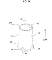
- the sleeve 240 includes a control cylinder 241.
- the control cylinder 241 includes a gap formation inner surface 242 and a holding outer surface 243 which extend cylindrically from the upper end to the lower end with the rotation axis 110 as a center.
- the gap formation inner surface 242 faces the inside in the radial direction
- the holding outer surface 243 faces the outside in the radial direction.
- Each of the cross sections of the gap formation inner surface 242 and the holding outer surface 243 on the plane orthogonal to the rotation axis 110 is constant along the rotation axis 110.
- the internal space defined by the gap formation inner surface 242 vertically penetrates the sleeve 240.
- the sleeve 240 includes a flange 244 and four ribs 245.
- the flange 244 annularly protrudes toward the outside in the radial direction from the lower end of the control cylinder 241.
- the ribs 245 protrude upward from the upper surface of the flange 244 along the holding outer surface 243.
- the ribs 245 are disposed at 90° intervals with the rotation axis 110 as a center when viewed from the top toward the bottom.
- Fig. 5B is a perspective view showing the cover 230 and the sleeve 240 which are combined to each other.
- the sleeve 240 is disposed in the space inside the holding inner surface 237 ( Fig. 4B ) of the sleeve holding portion 236. Since the cylindrical holding outer surface 243 ( Fig. 5A ) of the sleeve 240 and the cylindrical holding inner surface 237 ( Fig. 4B ) of the cover 230 are in contact with each other with a large area, the sleeve 240 does not move vertically in the sleeve holding portion 236 as long as a large force is not applied. Since each of the ribs 245 of the sleeve 240 is fitted into the notch 238 of the cover 230, the sleeve 240 and the sleeve holding portion 236 do not rotate relative to each other.
- the rotary member 300 includes a main body portion 310, movable terminals 320, springs 330, abutment members 340, a head 350, and a screw 360.
- the components of the rotary member 300 are fixed to each other such that the components do not rotate to each other around the rotation axis 110.
- the main body portion 310 had a cylindrical gap formation outer surface 311 which extends along the rotation axis 110 with the rotation axis 110 as a center.
- the main body portion 310 includes a third cylindrical bearing surface 312 which extends along the rotation axis 110 from the vicinity of the upper end of the gap formation outer surface 311 with the rotation axis 110 as a center. In the plane orthogonal to the rotation axis 110, the radius of the third bearing surface 312 is smaller than the radius of the gap formation outer surface 311.
- the main body portion 310 includes two spring holding portions 313 which protrude from the vicinity of the lower end of the gap formation outer surface 311 toward the outside in the radial direction.
- the two spring holding portions 313 protrude in directions opposite to each other with the rotation axis 110 as a center.
- a spring accommodation hole 314 which is open toward the outside in the radial direction is provided in each spring holding portion 313.
- the spring accommodation hole 314 extends in the radial direction inside the spring holding portion 313.
- the abutment member 340 is accommodated in each spring accommodation hole 314.
- the abutment member 340 is a hollow rod-shaped member extends in the radial direction.
- the outer end portion of the abutment member 340 in the radial direction is closed, and has a round shape.
- the inner end portion of the abutment member 340 in the radial direction is open.
- the outer end portion of the spring 330 ( Fig. 2 ) in the radial direction is disposed inside the abutment member 340, and the inner end portion of the spring 330 in the radial direction is fixed to the spring holding portion 313 in the rear portion of the spring accommodation hole 314.
- the abutment members 340 are accommodated in a state where compressive forces are applied to the springs 330 ( Fig. 2 ) along the radial direction. Accordingly, the springs 330 ( Fig. 2 ) elastically bias the abutment members 340 toward the outside in the radial direction.
- the main body portion 310 includes two terminal holding portions 315 which protrude from the vicinity of the lower end of the gap formation outer surface 311 toward the outside in the radial direction.
- the two terminal holding portions 315 protrude in directions opposite to each other with the rotation axis 110 as a center.
- the terminal holding portions 315 and the spring holding portions 313 are disposed at positions which are deviated by 90° with the rotation axis 110 as a center.
- the movable terminal 320 is attached to the upper surface of each terminal holding portion 315.
- the main body portion 310 includes a fourth bearing surface 316 which is disposed below the spring holding portions 313 and the terminal holing portions 315 and is open downward.
- the fourth bearing surface 316 is an approximately cylindrical surface which extends along the rotation axis 110 with the rotation axis 110 as a center.
- the fourth bearing surface 316 extends from the lower end of the main body portion 310 to a predetermined height.
- the fourth bearing surface 316 defines an internal space which faces the inside in the radial direction and has a hollow cylindrical shape.
- Notches 317 which are recessed toward the inside in the radial direction, slightly extend downward from the upper end on the upper end portion of the main body portion 310.
- the head 350 includes an operation portion 351, a regulation member 352, and an attachment portion 353.
- the operation portion 351 includes a disk-shaped member which has the rotation axis 110 as a center, and an edge portion which extend downward from the outer edge of the disk-shaped member.
- the regulation member 352 protrudes downward from the lower end of the edge portion of the operation portion 351.
- the attachment portion 353 cylindrically protrudes downward from the lower surface at the center of the operation portion 351.
- a portion of the attachment portion 353 is disposed inside the upper end of the main body portion 310, and is fixed to the main body portion 310 by the screw 360. As shown in Fig.
- ribs 354 are provided on the outer surface of the attachment portion 353 in the radial direction. Since the ribs 354 of the head 350 are fitted so as to be fixed to the notches 317 of the main body portion 310, the head 350 does not rotate relative to the main body portion 310.
- Fig. 7 is a view when the cross section taken along line 7-7 shown in Fig. 1 on the plane including the rotation axis 110 is viewed from an arrow direction. In Fig. 7 , only the cross section is shown, and the inner structure is omitted.
- the operation portion 351 of the head 350 is disposed outside the fixed member 200.
- the regulation member 352 shown in Fig. 6B is disposed so as to be movable inside the groove 233 shown in Fig. 4A .
- the head 350 is operated by hands of a user and rotates around the rotation axis 110, since the regulation member 352 rotates within only the range in which the groove 233 is positioned, the rotation angle between the fixed member 200 and the rotary member 300 is limited.
- the second bearing surface 232 of the fixed member 200 and the third bearing surface 312 of the rotary member 300 forms an upper bearing portion 121.
- Both of the second bearing surface 232 and the third bearing surface 312 have approximately cylindrical shapes, and approach each other.
- a first distance in the radial direction between the second bearing surface 232 and the third bearing surface 312 is extremely small. The first distance is small such that the fixed member 200 and the rotary member 300 are not largely deviated from each other in the radial direction.
- the second bearing surface 232 and the third bearing surface 312 are supported to each other such that the fixed member 200 and the rotary member 300 can smoothly rotate relative to each other according to the operation of the operation portion 351.
- the first bearing surface 213 of the fixed member 200 and the fourth bearing surface 316 of the rotary member 300 form a lower bearing portion 122.
- Both of the first bearing surface 213 and the fourth bearing surface 316 have approximately cylindrical shapes, and approach each other.
- a second distance in the radial direction between the first bearing surface 213 and the fourth bearing surface 316 is extremely small. The second distance is small such that the fixed member 200 and the rotary member 300 are not largely deviated from each other in the radial direction.
- the first bearing surface 213 and the fourth bearing surface 316 are supported to each other such that the fixed member 200 and the rotary member 300 can smoothly rotate relative to each other according to the operation of the operation portion 351.
- the control cylinder 241 of the sleeve 240 is fitted into the internal space defined by the holding inner surface 237 of the sleeve holding portion 236 of the fixed member 200.
- the holding inner surface 237 and the holding outer surface 243 of the sleeve 240 face each other and are in close-contact with each other.
- the gap formation inner surface 242 of the sleeve 240 and the gap formation outer surface 311 of the main body portion 310 of the rotary member 300 are disposed to face each other.
- Fig. 8 is a view when only a cross section taken along line 8-8 of Fig. 7 is viewed from the top toward the bottom.
- the viscous material 400 is interposed in a gap between the gap formation inner surface 242 and the gap formation outer surface 311.
- the viscous material 400 may completely fill the gap between the gap formation inner surface 242 and the gap formation outer surface 311, or may fill a portion of the gap.
- the viscous material 400 generates a resistance force when the fixed member 200 and the rotary member 300 rotate relative to each other. For example, after at least one of the gap formation inner surface 242 and the gap formation outer surface 311 is coated with the viscous material 400, assembly is performed.
- a third distance of the gap between the gap formation inner surface 242 and the gap formation outer surface 311 in the radial direction is approximately constant within a predetermined range along the rotation axis 110.
- the third distance is larger than the first distance of the upper bearing portion 121 and the second distance of the lower bearing portion 122.
- the third distance is small such that the viscous material 400 does not easily flow out.
- each of the first distance and the second distance is 0.05 mm or less.
- the third distance is approximately 0.1 to 0.5 mm.
- the third distance is not limited to this.
- the third distance is 10 times each of the first distance and the second distance.
- a member is not provided, which prevents the viscous material 400 from leaking from the gap between the gap formation inner surface 242 and the gap formation outer surface 311. If the gap between the gap formation inner surface 242 and the gap formation outer surface 311 and viscosity of the viscous material 400 are appropriately selected, leakage of the viscous material 400 which influences the operations does not occur even when it is used for a long time.
- the viscous material 400 grease or silicone grease can be appropriately used, in which a fluororesin such as polytetrafluoroethylene (PTFE) is included in olefin based oil.
- PTFE polytetrafluoroethylene
- a resistance generation portion 130 is configured by the spring holding portions 313, the springs 330, the abutment members 340, and the cam portion 214.
- the abutment members 340 are elastically biased toward the cam portion 214.
- the distance between the inner surface of the cam portion 214 facing the inner side in the radial direction and the rotation axis 110 is changed according to the angle position around the rotation axis 110.
- the fixed terminals 222 of the partition plate 220 shown in Fig. 3B are disposed on the rotation traj ectories of the movable terminals 320 shown in Fig. 6A .
- the fixed terminals 222 and the movable terminals 320 come into contact with each other or are separated from each other according to the position of the relative rotation between the fixed member 200 and the rotary member 300. Electric signals generated due to the contacts between the fixed terminals 222 and the movable terminals 320 are transmitted to the outside as inputs by wires (not shown).
- the fixed member 200 and the rotary member 300 shown in Fig. 7 rotate relative to each other around the rotation axis 110.
- the outer end portions of the abutment members 340 move along the inner surface of the cam portion 214.
- Fig. 9 is a graph in which a horizontal axis indicates an angle position of the rotary member 300 with respect to the fixed member 200 and a vertical axis indicates a resistance force applied to the operation portion 351.
- a horizontal axis indicates an angle position of the rotary member 300 with respect to the fixed member 200
- a vertical axis indicates a resistance force applied to the operation portion 351.
- a and C When viewed locally, two positions among the angle positions of the inner surface of the cam portion 214 farthest from the rotation axis 110 are indicated by position A and position C. When viewed locally, one position among the angle positions of the inner surface of the cam portion 214 closest from the rotation axis 110 is indicated by position B.
- a solid line graph 501 shows an example of a case where the viscous material 400 is used as the present embodiment, and a dotted line graph 502 shows Reference Example of a case where the viscous material 400 is not used.
- the abutment members 340 When the rotary member rotates from the position A to the position B, the abutment members 340 are pressed toward the inside in the radial direction by the cam portion 214, and the resistance force, which is applied from the cam portion 214 to the abutment members 340 in the direction opposite to the rotation direction, increases. Since the rotary member 300 integrally moves, the resistance force is transmitted from the abutment members 340 to the operation portion 351, and as shown by the graph 501 of the present embodiment in Fig. 9 , a user feels the maximum resistance force opposite to the rotation direction at the position B.
- the force b by which fingers of the user are pulled in the rotation direction is decreased by influences of viscous resistance of the viscous material 400, and the user does not feel an abrupt change. Accordingly, it is possible to provide smooth operation feeling to a user.
- the resistance force generated by the relative rotation between the fixed member 200 and the rotary member 300 is not transmitted to a user as it is. That is, after the resistance force is changed by the viscous material 400, it is possible to transmit the changed resistance force to the user.
- the input device 100 since the input device 100 includes the viscous material 400, it is possible to reduce the abrupt change of the resistance force generated by the resistance generation portion 130, and as a result, it is possible to provide smooth operation feeling to a user.
- the upper bearing portion 121 and the lower bearing portion 122 are not coated with the viscous material 400.
- the portion between the abutment members 340 and the cam portion 214 of the resistance generation portion 130 is not coated with the viscous material 400. That is, since the viscous material 400 is positioned at the position different from that of the resistance generation portion 130, it is possible to simplify the structure of the resistance generation portion 130. In a case where the viscous material 400 is present in the resistance generation portion 130, a large sealing mechanism for holding the viscous material 400 is required. However, according to the present embodiment, a large sealing mechanism is not required. In the case where the viscous material 400 is present in the resistance generation portion 130, large amounts of viscous materials 400 are required.
- the coating of the viscous material 400 is thinly applied, compared to the case where the viscous material 400 is present in the resistance generation portion 130, the amount of the required viscous material 400 decreases.
- a leakage preventing structure is not required, which is required in a case where the resistance generation portion 130 is embedded into the viscous material 400.
- An input device 600 of Fig. 10 is a modification example of the input device 100 shown in Fig. 7 .
- the input device 600 of the modification example includes a sleeve 640 instead of the sleeve 240 of Fig. 7 .
- the sleeve 640 of the modification example has a structure in which the control cylinder 241 of the sleeve 240 of Fig. 7 is shortened in the vertical direction, and other structures are similar to those of the sleeve 240 of Fig. 7 .
- a gap formation inner surface 642 of a control cylinder 641 of the modification example is shorter than the gap formation inner surface 242 of Fig. 7 in the vertical direction, and a holding outer surface 643 of the control cylinder 641 of the modification example is shorter than the holding outer surface 243 of Fig. 7 in the vertical direction. Since a length of the gap formed between the gap formation inner surface 642 and the gap formation outer surface 311 of the rotary member 300 in the vertical direction in the modification example is shorter than that of Fig. 7 , compared to the case of Fig. 7 , the amount of the viscous material 400 decreases.
- the sleeve 640 and the sleeve 240 have approximately cylindrical shapes, it is possible to simply change the region in which the viscous material 400 is present by only changing the lengths of the sleeve 640 and the sleeve 240.
- the resistance force felt by a user is changed according to the amount of the viscous material 400, and as the amount of the viscous material 400 decreases, a user is more difficult to feel the resistance force generated by the viscous material 400. Accordingly, as the sleeve 640 is shortened, a user more easily feels the resistance force generated by the resistance generation portion 130 directly.
- suppression with respect to the abrupt change of the resistance force generated by the resistance generation portion 130 according to the rotation can be controlled by selecting the length of the sleeve 640.
- other structures except for the sleeve 640 can be used in common. Accordingly, according to the present embodiment, it is possible to easily manufacture the input devices, in which the resistance forces felt by a user are different from each other, using common members. Since the sleeve 640 and the sleeve 240 can be put in and out from the lower end of the sleeve holding portion 236, manufacturing and replacement are easily performed.
- the present invention is not limited to the above-described embodiment and modification example. That is, a person skilled in the art may apply various modifications, combinations, sub-combinations, and replacements to the components of the above-described embodiment and modification example within a technical scope of the present invention and an equivalent range thereof.
- the present invention can be applied to the input device which is mounted on a vehicle or the like and performs input.
Landscapes
- Engineering & Computer Science (AREA)
- General Engineering & Computer Science (AREA)
- Rotary Switch, Piano Key Switch, And Lever Switch (AREA)
- Physics & Mathematics (AREA)
- Electromagnetism (AREA)
- Mechanical Engineering (AREA)
Description
- This application claims the benefit of Japanese Patent Application No.
2015-167785 filed on August 27, 2015 - The present invention relates to an input device.
- Japanese Unexamined Patent Application Publication No.
2007-201415 2007-201415 - However, in the input device disclosed in Japanese Unexamined Patent Application Publication No.
2007-201415 - The present invention provides an input device by which a resistance force generated according to a relative rotation between members can be changed.
- According to the present invention, there is provided an input device which includes a first member and a second member and which is configured to perform input according to a relative rotation between the first member and the second member, including: a bearing portion configured to rotatably support the first member and the second member; a gap which is formed between the first member and the second member at a position different from that of the bearing portion; and a viscous material which is present in the gap and is in contact with the first member and the second member.
- According to this configuration, it is possible to change a resistance force generated according to the relative rotation between the members.
- Preferably, in the input device of the present invention, a distance between the first member and the second member in the gap may be greater than a distance between the first member and the second member in the bearing portion.
- According to this configuration, it is possible to change the resistance force generated according to the relative rotation between the members.
- Preferably, in the input device of the present invention, one of the first member and the second member may include a sleeve and a sleeve holding portion configured to hold the sleeve, and the other of the first member and the second member, and the sleeve may form the gap.
- Accordingly, since the structure of the gap can be changed by replacing the sleeve, it is possible to manufacture a plurality of kinds of input device having resistance forces different from each other while using a common structure.
- Preferably, the input device of the present invention further includes a resistance generation portion configured to generate a resistance force according to a relative rotation angle between the first member and the second member, in which the viscous material may be in contact with the first member and the second member at a position different from that of the resistance generation portion.
- According to this configuration, it is possible to change the resistance force generated by the resistance generation portion according to the relative rotation of the members. Since the viscous material is positioned at a position different from that of the resistance generation portion, it is possible to simplify the structure of the resistance generation portion.
- Preferably, in the input device of the present invention, the other member may include a cylindrical gap formation outer surface, the sleeve holding portion may include a cylindrical holding inner surface which is positioned outside the gap formation outer surface, the sleeve may include a cylindrical holding outer surface which is in contact with the inner portion of the holding inner surface and a cylindrical gap formation inner surface which is positioned outside the gap formation outer surface, and the gap may be formed between the gap formation outer surface and the gap formation inner surface.
- According to this configuration, since the sleeve has an approximately cylindrical shape, it is possible to simply change an extendable region of the gap between the gap formation outer length of the sleeve.
-
-
Fig. 1 is a perspective view of an input device according to an embodiment of the present invention; -
Fig. 2 is an exploded perspective view of the input device shown inFig. 1 ; -
Fig. 3A is a perspective view of a base portion shown inFig. 2 ; -
Fig. 3B is a bottom view of a partition plate shown inFig. 2 ; -
Fig. 4A is a perspective view of a cover shown inFig. 2 when viewed obliquely from the top; -
Fig. 4B is a perspective view of the cover shown inFig. 2 when viewed obliquely from the bottom; -
Fig. 5A is a perspective view of a sleeve shown inFig. 2 ; -
Fig. 5B is a perspective view of the cover and the sleeve shown inFig. 2 when viewed obliquely from the bottom; -
Fig. 6A is a perspective view of a rotary member shown inFig. 2 when viewed obliquely from the top; -
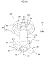
Fig. 6B is a perspective view of the rotary member shown inFig. 2 when viewed obliquely from the bottom; -
Fig. 7 is a sectional view taken along line 7-7 of the input device shown inFig. 1 ; -
Fig. 8 is a sectional view taken along line 8-8 of the input device shown inFig. 7 ; -
Fig. 9 is a graph showing a relationship between a rotation angle and a resistance force; and -
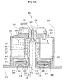
Fig. 10 is a sectional view of an input device of a modification example. - Hereinafter, an input device according to an embodiment of the present invention will be described. As shown in a perspective view of
Fig. 1 , theinput device 100 includes a fixedmember 200 and arotary member 300 which can rotate in both directions relative to each other about arotation axis 110 along a vertical direction, and includes aviscous material 400 described below with reference toFig. 8 . Thefixed member 200 of the present embodiment is fixed to a vehicle, and therotary member 300 is operated by fingers of a user who performs input. The input based on rotation is transmitted to the outside as electric signals by a wire (not shown). - In addition, the vertical direction is defined for convenience of descriptions, and does not define a direction in an actual use. A direction which passes the
rotation axis 110 so as to be orthogonal to therotation axis 110 is referred to as a radial direction. A radially outward direction is referred to as a direction away from therotation axis 110, and a radially inward direction is referred to as a direction toward therotation axis 110. Regardless of presence or absence of "approximately", a shape used in the following description does not strictly limit each component to a geometric shape, and is suggested so as to exemplify a schematic shape as an example which realizes a technical idea of the present embodiment. - First, the structure of the fixed
member 200 will be described. As shown in an exploded perspective view ofFig. 2 , the fixedmember 200 includes abase portion 210, apartition plate 220, acover 230, asleeve 240, andscrews 250. The components of thefixed member 200 are fixed to each other such that the components do not rotate to each other around therotation axis 110. - As shown in the perspective view of
Fig. 3A , thebase portion 210 includes aseat portion 211, a first bearingportion 212, acam portion 214, a first wall portion, 215,outer ribs 216,upper ribs 217, andlower bosses 218. - The
seat portion 211 extends in a plate shape along a plane orthogonal to therotation axis 110. The first bearingportion 212 protrudes approximately cylindrically upward from the upper surface of theseat portion 211 along therotation axis 110. A first bearingsurface 213 which is a cylindrical outer surface of the first bearingportion 212 extends along therotation axis 110 with therotation axis 110 as a center. A hole which penetrates thefirst bearing portion 212 and theseat portion 211 in the vertical direction is provided at the center of thefirst bearing portion 212. Thecam portion 214 extends in a plate shape upward from theseat portion 211. Thecam portion 214 surrounds thefirst bearing portion 212 from the outside in the radial direction. Distances between thecam portion 214 and the outer surface of thefirst bearing portion 212 are different from each other according to the angle position around therotation axis 110. - The
first wall portion 215 extends upward from theseat portion 211 so as to surround thecam portion 214 from the outside in the radial direction. When thefirst wall portion 215 is viewed from the top toward the bottom, thefirst wall portion 215 has an approximately rectangular shape. Theouter ribs 216 extends upward to a lower position than the uppermost portion of thefirst wall portion 215 from theseat portion 211 along the outer surface of thefirst wall portion 215. When theouter ribs 216 are viewed from the top toward the bottom, each of theouter ribs 216 protrudes toward the outside in the radial direction from the outer surface of thefirst wall portion 215 in the vicinity of the center of each of four sides of thefirst wall portion 215 having an approximately rectangular shape. Theupper ribs 217 extend upward from the upper edge of thefirst wall portion 215. When theupper ribs 217 are viewed from the top toward the bottom, each of theupper ribs 217 is positioned in the vicinity of the center of each of the four sides of thefirst wall portion 215 having an approximately rectangular shape. Fourlower bosses 218 are provided so as to be close to corners of thefirst wall portion 215 having an approximately rectangular shape between thecam portion 214 and thefirst wall portion 215. Each of the fourlower bosses 218 protrudes upward from theseat portion 211. A screw hole which penetrates each of thelower bosses 218 and theseat portion 211 is provided at the center of eachlower boss 218. - As shown in a bottom view of
Fig. 3B , thepartition plate 220 includes a plate-shapedmember 221 having an approximately rectangular shape and fixedterminals 222. Acircular center hole 223 having a center which coincides with therotation axis 110 is provided in the plate-shapedmember 221. Thecenter hole 223 penetrates the plate-shapedmember 221 vertically. - A
notch 224 which is recessed toward the inside in the radial direction is provided in the vicinity of the center of each of four linear outer edges of the plate-shapedmember 221 having an approximately rectangular shape. Four throughholes 225, which overlap the fourlower bosses 218 ofFig. 3A in the vertical direction, are provided in the vicinities of the four corners of the plate-shapedmember 221 so as to penetrate the plate-shapedmember 221 in the vertical direction. The fixedterminals 222 are a plurality of thin sheet-shaped metal pieces which are provided on the lower surface of the plate-shapedmember 221, and are disposed in a fan shape outside thecenter hole 223 in the radial direction. - When viewed from the top toward the bottom, the outer edge positioned outside the
partition plate 220 in the radial direction shown inFig. 3B approximately coincides with the outer edge positioned outside thefirst wall portion 215 in the radial direction shown inFig. 3A . Since theupper ribs 217 of thebase portion 210 are fitted into thenotches 224 of thepartition plate 220, a relative rotation between thepartition plate 220 and thebase portion 210 is prevented. - As shown in a perspective view of
Fig. 4A which is a view when thecover 230 is obliquely viewed from the top, the outline of thecover 230 is an approximately rectangular parallelepiped shape, and thecover 230 defines a hollow internal space. As shown in a perspective view ofFig. 4B which is a view when thecover 230 is obliquely viewed from the bottom, thecover 230 is open downward. - As shown in
Fig. 4A , thecover 230 includes anupper plate 231 which extends substantially along a plane approximately orthogonal to therotation axis 110. Theupper plate 231 has an approximately rectangular shape when viewed from the top toward the bottom. Theupper plate 231 gently protrudes upward in the vicinity of the center thereof. A columnarsecond bearing surface 232 having a center axis along therotation axis 110 is provided at the center of theupper plate 231. Thesecond bearing surface 232 defines a hole which penetrates theupper plate 231 in the vertical direction. In theupper plate 231, agroove 233 which is open upward is provided further outside in the radial direction than thesecond bearing surface 232. Thegroove 233 extends such that thegroove 233 does not completely surround therotation axis 110 along a circumference of a circle which has therotation axis 110 as a center. - As shown in
Fig. 4B , thecover 230 includes a plate-shapedsecond wall portion 234 which extends downward from the outer edge of theupper plate 231. In the lower edge of thesecond wall portion 234 having an approximately rectangular shape when viewed from the bottom toward the top, anotch 235 which is recessed upward is provided at the center of each side. - The
cover 230 includes asleeve holding portion 236. Thesleeve holding portion 236 has an approximately cylindrical shape, and extends downward in a cylindrical shape from the lower surface of theupper plate 231 outside the lower end of thesecond bearing surface 232 in the radial direction. A cylindrical holdinginner surface 237 of thesleeve holding portion 236 has an approximately cylindrical shape, and has a center axis which coincides with therotation axis 110. The cross section of the holdinginner surface 237 on the plane orthogonal to therotation axis 110 is approximately constant along therotation axis 110. The upper end of the space defined inside the holdinginner surface 237 communicates with the space defined inside thesecond bearing surface 232.Notches 238, which are disposed at 90° intervals with therotation axis 110 as a center when viewed from the bottom toward the top and are recessed upward, are provided on the lower end of thesleeve holding portion 236. - The
cover 230 includes fourupper bosses 239. The fourupper bosses 239 are disposed between thesecond wall portion 234 and thesleeve holding portion 236, and are close to the corners of thesecond wall portion 234 having an approximately rectangular shape. Each of the fourupper bosses 239 protrudes downward from theupper plate 231, and includes a screw hole which is open downward. - The
second wall portion 234 of the cover 230 (Fig. 4B ) is disposed so as to surround the outer side of thefirst wall portion 215 of the base portion 210 (Fig. 3A ) in the radial direction. As shown inFig. 1 , since the fourouter ribs 216 of thebase portion 210 are respectively fitted into the fournotches 235 of thecover 230, a relative rotation between thecover 230 and thebase portion 210 is prevented. Thebase portion 210, thepartition plate 220, and thecover 230 shown inFig. 2 are fixed to each other at four locations by screws 250 (Fig. 2 ) which pass through thelower bosses 218 of the base portion 210 (Fig. 3A ), the throughholes 225 of the partition plate 220 (Fig. 3B ), and theupper bosses 239 of the cover 230 (Fig. 4B ). - As shown in a perspective view of
Fig. 5A , thesleeve 240 includes acontrol cylinder 241. Thecontrol cylinder 241 includes a gap formationinner surface 242 and a holdingouter surface 243 which extend cylindrically from the upper end to the lower end with therotation axis 110 as a center. The gap formationinner surface 242 faces the inside in the radial direction, and the holdingouter surface 243 faces the outside in the radial direction. Each of the cross sections of the gap formationinner surface 242 and the holdingouter surface 243 on the plane orthogonal to therotation axis 110 is constant along therotation axis 110. The internal space defined by the gap formationinner surface 242 vertically penetrates thesleeve 240. - The
sleeve 240 includes aflange 244 and fourribs 245. Theflange 244 annularly protrudes toward the outside in the radial direction from the lower end of thecontrol cylinder 241. Theribs 245 protrude upward from the upper surface of theflange 244 along the holdingouter surface 243. Theribs 245 are disposed at 90° intervals with therotation axis 110 as a center when viewed from the top toward the bottom. -
Fig. 5B is a perspective view showing thecover 230 and thesleeve 240 which are combined to each other. Thesleeve 240 is disposed in the space inside the holding inner surface 237 (Fig. 4B ) of thesleeve holding portion 236. Since the cylindrical holding outer surface 243 (Fig. 5A ) of thesleeve 240 and the cylindrical holding inner surface 237 (Fig. 4B ) of thecover 230 are in contact with each other with a large area, thesleeve 240 does not move vertically in thesleeve holding portion 236 as long as a large force is not applied. Since each of theribs 245 of thesleeve 240 is fitted into thenotch 238 of thecover 230, thesleeve 240 and thesleeve holding portion 236 do not rotate relative to each other. - Next, the structure of the
rotary member 300 will be described. As shown in the exploded perspective view ofFig. 2 , therotary member 300 includes amain body portion 310,movable terminals 320, springs 330,abutment members 340, ahead 350, and ascrew 360. The components of therotary member 300 are fixed to each other such that the components do not rotate to each other around therotation axis 110. - As shown in a perspective view of
Fig. 6A which is a view when themain body portion 310 is obliquely viewed from the top, themain body portion 310 had a cylindrical gap formationouter surface 311 which extends along therotation axis 110 with therotation axis 110 as a center. Themain body portion 310 includes a thirdcylindrical bearing surface 312 which extends along therotation axis 110 from the vicinity of the upper end of the gap formationouter surface 311 with therotation axis 110 as a center. In the plane orthogonal to therotation axis 110, the radius of thethird bearing surface 312 is smaller than the radius of the gap formationouter surface 311. - The
main body portion 310 includes twospring holding portions 313 which protrude from the vicinity of the lower end of the gap formationouter surface 311 toward the outside in the radial direction. The twospring holding portions 313 protrude in directions opposite to each other with therotation axis 110 as a center. Aspring accommodation hole 314 which is open toward the outside in the radial direction is provided in eachspring holding portion 313. - The
spring accommodation hole 314 extends in the radial direction inside thespring holding portion 313. Theabutment member 340 is accommodated in eachspring accommodation hole 314. Theabutment member 340 is a hollow rod-shaped member extends in the radial direction. The outer end portion of theabutment member 340 in the radial direction is closed, and has a round shape. The inner end portion of theabutment member 340 in the radial direction is open. - The outer end portion of the spring 330 (
Fig. 2 ) in the radial direction is disposed inside theabutment member 340, and the inner end portion of thespring 330 in the radial direction is fixed to thespring holding portion 313 in the rear portion of thespring accommodation hole 314. Theabutment members 340 are accommodated in a state where compressive forces are applied to the springs 330 (Fig. 2 ) along the radial direction. Accordingly, the springs 330 (Fig. 2 ) elastically bias theabutment members 340 toward the outside in the radial direction. - The
main body portion 310 includes two terminal holdingportions 315 which protrude from the vicinity of the lower end of the gap formationouter surface 311 toward the outside in the radial direction. The twoterminal holding portions 315 protrude in directions opposite to each other with therotation axis 110 as a center. When viewed from the top toward the bottom, theterminal holding portions 315 and thespring holding portions 313 are disposed at positions which are deviated by 90° with therotation axis 110 as a center. Themovable terminal 320 is attached to the upper surface of each terminal holdingportion 315. - As shown in a perspective view of
Fig. 6B which is a view when themain body portion 310 is obliquely viewed from the bottom, themain body portion 310 includes afourth bearing surface 316 which is disposed below thespring holding portions 313 and theterminal holing portions 315 and is open downward. Thefourth bearing surface 316 is an approximately cylindrical surface which extends along therotation axis 110 with therotation axis 110 as a center. Thefourth bearing surface 316 extends from the lower end of themain body portion 310 to a predetermined height. Thefourth bearing surface 316 defines an internal space which faces the inside in the radial direction and has a hollow cylindrical shape. -
Notches 317, which are recessed toward the inside in the radial direction, slightly extend downward from the upper end on the upper end portion of themain body portion 310. - As shown in
Fig. 6B , thehead 350 includes anoperation portion 351, aregulation member 352, and anattachment portion 353. Theoperation portion 351 includes a disk-shaped member which has therotation axis 110 as a center, and an edge portion which extend downward from the outer edge of the disk-shaped member. Theregulation member 352 protrudes downward from the lower end of the edge portion of theoperation portion 351. Theattachment portion 353 cylindrically protrudes downward from the lower surface at the center of theoperation portion 351. As shown inFig. 7 described below, a portion of theattachment portion 353 is disposed inside the upper end of themain body portion 310, and is fixed to themain body portion 310 by thescrew 360. As shown inFig. 6B ,ribs 354 are provided on the outer surface of theattachment portion 353 in the radial direction. Since theribs 354 of thehead 350 are fitted so as to be fixed to thenotches 317 of themain body portion 310, thehead 350 does not rotate relative to themain body portion 310. -
Fig. 7 is a view when the cross section taken along line 7-7 shown inFig. 1 on the plane including therotation axis 110 is viewed from an arrow direction. InFig. 7 , only the cross section is shown, and the inner structure is omitted. - The
operation portion 351 of thehead 350 is disposed outside the fixedmember 200. Theregulation member 352 shown inFig. 6B is disposed so as to be movable inside thegroove 233 shown inFig. 4A . When thehead 350 is operated by hands of a user and rotates around therotation axis 110, since theregulation member 352 rotates within only the range in which thegroove 233 is positioned, the rotation angle between the fixedmember 200 and therotary member 300 is limited. - In the upper portion, the
second bearing surface 232 of the fixedmember 200 and thethird bearing surface 312 of therotary member 300 forms anupper bearing portion 121. Both of thesecond bearing surface 232 and thethird bearing surface 312 have approximately cylindrical shapes, and approach each other. A first distance in the radial direction between thesecond bearing surface 232 and thethird bearing surface 312 is extremely small. The first distance is small such that the fixedmember 200 and therotary member 300 are not largely deviated from each other in the radial direction. However, thesecond bearing surface 232 and thethird bearing surface 312 are supported to each other such that the fixedmember 200 and therotary member 300 can smoothly rotate relative to each other according to the operation of theoperation portion 351. - In the lower portion, the
first bearing surface 213 of the fixedmember 200 and thefourth bearing surface 316 of therotary member 300 form alower bearing portion 122. Both of thefirst bearing surface 213 and thefourth bearing surface 316 have approximately cylindrical shapes, and approach each other. A second distance in the radial direction between thefirst bearing surface 213 and thefourth bearing surface 316 is extremely small. The second distance is small such that the fixedmember 200 and therotary member 300 are not largely deviated from each other in the radial direction. However, thefirst bearing surface 213 and thefourth bearing surface 316 are supported to each other such that the fixedmember 200 and therotary member 300 can smoothly rotate relative to each other according to the operation of theoperation portion 351. - The
control cylinder 241 of thesleeve 240 is fitted into the internal space defined by the holdinginner surface 237 of thesleeve holding portion 236 of the fixedmember 200. The holdinginner surface 237 and the holdingouter surface 243 of thesleeve 240 face each other and are in close-contact with each other. The gap formationinner surface 242 of thesleeve 240 and the gap formationouter surface 311 of themain body portion 310 of therotary member 300 are disposed to face each other. -
Fig. 8 is a view when only a cross section taken along line 8-8 ofFig. 7 is viewed from the top toward the bottom. Theviscous material 400 is interposed in a gap between the gap formationinner surface 242 and the gap formationouter surface 311. Theviscous material 400 may completely fill the gap between the gap formationinner surface 242 and the gap formationouter surface 311, or may fill a portion of the gap. Theviscous material 400 generates a resistance force when the fixedmember 200 and therotary member 300 rotate relative to each other. For example, after at least one of the gap formationinner surface 242 and the gap formationouter surface 311 is coated with theviscous material 400, assembly is performed. - A third distance of the gap between the gap formation
inner surface 242 and the gap formationouter surface 311 in the radial direction is approximately constant within a predetermined range along therotation axis 110. The third distance is larger than the first distance of theupper bearing portion 121 and the second distance of thelower bearing portion 122. The third distance is small such that theviscous material 400 does not easily flow out. For example, each of the first distance and the second distance is 0.05 mm or less. However, the first and second distances are not limited to this. The third distance is approximately 0.1 to 0.5 mm. However, the third distance is not limited to this. Preferably, the third distance is 10 times each of the first distance and the second distance. - In the present embodiment, a member is not provided, which prevents the
viscous material 400 from leaking from the gap between the gap formationinner surface 242 and the gap formationouter surface 311. If the gap between the gap formationinner surface 242 and the gap formationouter surface 311 and viscosity of theviscous material 400 are appropriately selected, leakage of theviscous material 400 which influences the operations does not occur even when it is used for a long time. For example, as theviscous material 400, grease or silicone grease can be appropriately used, in which a fluororesin such as polytetrafluoroethylene (PTFE) is included in olefin based oil. - As shown in
Fig. 7 , aresistance generation portion 130 is configured by thespring holding portions 313, thesprings 330, theabutment members 340, and thecam portion 214. Bysprings 330 which are accommodated in the lower spring accommodation holes 314, theabutment members 340 are elastically biased toward thecam portion 214. The distance between the inner surface of thecam portion 214 facing the inner side in the radial direction and therotation axis 110 is changed according to the angle position around therotation axis 110. When the fixedmember 200 and therotary member 300 rotate relative to each other, the outer end portions of theabutment members 340 in the radial direction move in the radial direction according to the distance between the inner surface of thecam portion 214 and therotation axis 110. - The fixed
terminals 222 of thepartition plate 220 shown inFig. 3B are disposed on the rotation traj ectories of themovable terminals 320 shown inFig. 6A . The fixedterminals 222 and themovable terminals 320 come into contact with each other or are separated from each other according to the position of the relative rotation between the fixedmember 200 and therotary member 300. Electric signals generated due to the contacts between the fixedterminals 222 and themovable terminals 320 are transmitted to the outside as inputs by wires (not shown). - If a user operates the
operation portion 351 of thehead 350, the fixedmember 200 and therotary member 300 shown inFig. 7 rotate relative to each other around therotation axis 110. At the time of the rotation, the outer end portions of theabutment members 340 move along the inner surface of thecam portion 214. -
Fig. 9 is a graph in which a horizontal axis indicates an angle position of therotary member 300 with respect to the fixedmember 200 and a vertical axis indicates a resistance force applied to theoperation portion 351. When a user rotates therotary member 300 in a direction, as the resistance force in the direction opposite to the rotation direction increases, the graph is plotted further upward in the vertical axis. - When viewed locally, two positions among the angle positions of the inner surface of the
cam portion 214 farthest from therotation axis 110 are indicated by position A and position C. When viewed locally, one position among the angle positions of the inner surface of thecam portion 214 closest from therotation axis 110 is indicated by position B. Asolid line graph 501 shows an example of a case where theviscous material 400 is used as the present embodiment, and a dottedline graph 502 shows Reference Example of a case where theviscous material 400 is not used. - When the rotary member rotates from the position A to the position B, the
abutment members 340 are pressed toward the inside in the radial direction by thecam portion 214, and the resistance force, which is applied from thecam portion 214 to theabutment members 340 in the direction opposite to the rotation direction, increases. Since therotary member 300 integrally moves, the resistance force is transmitted from theabutment members 340 to theoperation portion 351, and as shown by thegraph 501 of the present embodiment inFig. 9 , a user feels the maximum resistance force opposite to the rotation direction at the position B. - When the rotary member rotates from the position B to the position C, the
abutment members 340 are pressed toward the outside in the radial direction by the forces of thesprings 330 and receive forces in the same direction as the rotation direction from thecam portion 214, and the resistance force applied from thecam portion 214 to theabutment members 340 gradually decreases. As a result, as shown in thegraph 502 of Reference Example, if theviscous material 400 is not present, a user feels a force by which fingers of the user are pulled in the rotation direction, as shown by a portion in which the resistance force becomes 0 or less before and after the position C beyond the position B. Meanwhile, in thegraph 501 of the present embodiment, since theviscous material 400 is provided, the force b by which fingers of the user are pulled in the rotation direction is decreased by influences of viscous resistance of theviscous material 400, and the user does not feel an abrupt change. Accordingly, it is possible to provide smooth operation feeling to a user. - According to the present embodiment, the resistance force generated by the relative rotation between the fixed
member 200 and therotary member 300 is not transmitted to a user as it is. That is, after the resistance force is changed by theviscous material 400, it is possible to transmit the changed resistance force to the user. According to the present embodiment, since theinput device 100 includes theviscous material 400, it is possible to reduce the abrupt change of the resistance force generated by theresistance generation portion 130, and as a result, it is possible to provide smooth operation feeling to a user. - In addition, in the present embodiment, the
upper bearing portion 121 and thelower bearing portion 122 are not coated with theviscous material 400. Moreover, the portion between theabutment members 340 and thecam portion 214 of theresistance generation portion 130 is not coated with theviscous material 400. That is, since theviscous material 400 is positioned at the position different from that of theresistance generation portion 130, it is possible to simplify the structure of theresistance generation portion 130. In a case where theviscous material 400 is present in theresistance generation portion 130, a large sealing mechanism for holding theviscous material 400 is required. However, according to the present embodiment, a large sealing mechanism is not required. In the case where theviscous material 400 is present in theresistance generation portion 130, large amounts ofviscous materials 400 are required. However, according to the present embodiment, since the coating of theviscous material 400 is thinly applied, compared to the case where theviscous material 400 is present in theresistance generation portion 130, the amount of the requiredviscous material 400 decreases. According to the present embodiment, since surface tension is generated by applying only thin coating of theviscous material 400 and it is possible to prevent theviscous material 400 from leaking out due to the surface tension, for example, a leakage preventing structure is not required, which is required in a case where theresistance generation portion 130 is embedded into theviscous material 400. - An
input device 600 ofFig. 10 is a modification example of theinput device 100 shown inFig. 7 . Theinput device 600 of the modification example includes asleeve 640 instead of thesleeve 240 ofFig. 7 . Thesleeve 640 of the modification example has a structure in which thecontrol cylinder 241 of thesleeve 240 ofFig. 7 is shortened in the vertical direction, and other structures are similar to those of thesleeve 240 ofFig. 7 . - A gap formation
inner surface 642 of acontrol cylinder 641 of the modification example is shorter than the gap formationinner surface 242 ofFig. 7 in the vertical direction, and a holdingouter surface 643 of thecontrol cylinder 641 of the modification example is shorter than the holdingouter surface 243 ofFig. 7 in the vertical direction. Since a length of the gap formed between the gap formationinner surface 642 and the gap formationouter surface 311 of therotary member 300 in the vertical direction in the modification example is shorter than that ofFig. 7 , compared to the case ofFig. 7 , the amount of theviscous material 400 decreases. - According to the embodiment and the modification example, since the
sleeve 640 and thesleeve 240 have approximately cylindrical shapes, it is possible to simply change the region in which theviscous material 400 is present by only changing the lengths of thesleeve 640 and thesleeve 240. The resistance force felt by a user is changed according to the amount of theviscous material 400, and as the amount of theviscous material 400 decreases, a user is more difficult to feel the resistance force generated by theviscous material 400. Accordingly, as thesleeve 640 is shortened, a user more easily feels the resistance force generated by theresistance generation portion 130 directly. That is, suppression with respect to the abrupt change of the resistance force generated by theresistance generation portion 130 according to the rotation can be controlled by selecting the length of thesleeve 640. Meanwhile, in various input devices in which the resistance forces felt by a user are different from each other, other structures except for thesleeve 640 can be used in common. Accordingly, according to the present embodiment, it is possible to easily manufacture the input devices, in which the resistance forces felt by a user are different from each other, using common members. Since thesleeve 640 and thesleeve 240 can be put in and out from the lower end of thesleeve holding portion 236, manufacturing and replacement are easily performed. - The present invention is not limited to the above-described embodiment and modification example. That is, a person skilled in the art may apply various modifications, combinations, sub-combinations, and replacements to the components of the above-described embodiment and modification example within a technical scope of the present invention and an equivalent range thereof.
- The present invention can be applied to the input device which is mounted on a vehicle or the like and performs input.
- It should be understood by those skilled in the art that various modifications, combinations, sub-combinations and alterations may occur depending on design requirements and other factors insofar as they are within the scope of the appended claims of the equivalents thereof.
Claims (5)
- An input device (100) which includes a first member (200) and a second member (300) and which is configured to perform input according to a relative rotation between the first member (200) and the second member (300), comprising:a bearing portion (121, 122) configured to rotatably support the first member (200) and the second member (300);a gap which is formed between the first member (200) and the second member (300) at a position different from that of the bearing portion (121, 122); anda viscous material (400) which is present in the gap and is in contact with the first member (200) and the second member (300).
- The input device (100) according to claim 1,
wherein a distance between the first member (200) and the second member (300) in the gap is greater than a distance between the first member (200) and the second member (300) in the bearing portion (121, 122). - The input device (100) according to claim 1 or 2,
wherein one of the first member (200) and the second member (300) includes a sleeve (240, 640) and a sleeve holding portion (236) configured to hold the sleeve (240, 640), and
wherein the other of the first member (200) and the second member (300), and the sleeve (240, 640) form the gap. - The input device (100) according to any one of claims 1 to 3, further comprising:a resistance generation portion (130) configured to generate a resistance force according to a relative rotation angle between the first member (200) and the second member (300),wherein the viscous material (400) is in contact with the first member (200) and the second member (300) at a position different from that of the resistance generation portion (130).
- The input device (100) according to any one of claims 1 to 4,
wherein the other member includes a cylindrical gap formation outer surface (311),
wherein the sleeve holding portion (236) includes a cylindrical holding inner surface (237) which is positioned outside the gap formation outer surface (311),
wherein the sleeve (240, 640) includes a cylindrical holding outer surface (243) which is in contact with the inner portion of the holding inner surface (237) and a cylindrical gap formation inner surface (642) which is positioned outside the gap formation outer surface (311), and
wherein the gap is formed between the gap formation outer surface (311) and the gap formation inner surface (642).
Applications Claiming Priority (1)
| Application Number | Priority Date | Filing Date | Title |
|---|---|---|---|
| JP2015167785A JP6469551B2 (en) | 2015-08-27 | 2015-08-27 | Input device |
Publications (2)
| Publication Number | Publication Date |
|---|---|
| EP3142135A1 true EP3142135A1 (en) | 2017-03-15 |
| EP3142135B1 EP3142135B1 (en) | 2019-06-19 |
Family
ID=56615862
Family Applications (1)
| Application Number | Title | Priority Date | Filing Date |
|---|---|---|---|
| EP16182571.6A Active EP3142135B1 (en) | 2015-08-27 | 2016-08-03 | Input device |
Country Status (3)
| Country | Link |
|---|---|
| EP (1) | EP3142135B1 (en) |
| JP (1) | JP6469551B2 (en) |
| CN (1) | CN106481725B (en) |
Cited By (1)
| Publication number | Priority date | Publication date | Assignee | Title |
|---|---|---|---|---|
| FR3106532A1 (en) * | 2020-01-24 | 2021-07-30 | Psa Automobiles Sa | Motor vehicle dashboard rotary control knob |
Citations (4)
| Publication number | Priority date | Publication date | Assignee | Title |
|---|---|---|---|---|
| EP0414899A1 (en) * | 1988-10-25 | 1991-03-06 | Matsushita Electric Industrial Co., Ltd. | Rotary encoder |
| JP2007201415A (en) | 2005-12-28 | 2007-08-09 | Alps Electric Co Ltd | Rotary type electrical component |
| US20090152086A1 (en) * | 2007-12-18 | 2009-06-18 | Hiroaki Hisamune | Rotating operation type electronic component, and electronic device including the same |
| WO2014087783A1 (en) * | 2012-12-07 | 2014-06-12 | 東京コスモス電機株式会社 | Rotary-operation-type electronic component |
Family Cites Families (6)
| Publication number | Priority date | Publication date | Assignee | Title |
|---|---|---|---|---|
| JP3763169B2 (en) * | 1996-08-23 | 2006-04-05 | 松下電器産業株式会社 | Rotating operation type electronic component with push switch and manufacturing method thereof |
| US6156986A (en) * | 1999-12-30 | 2000-12-05 | Jing Mold Enterprise Co., Ltd. | Computer key switch |
| JP2004172007A (en) * | 2002-11-21 | 2004-06-17 | Alps Electric Co Ltd | Rotary electronic parts |
| CN201107801Y (en) * | 2007-07-30 | 2008-08-27 | 升威电子制品(东莞)有限公司 | Automatic resetting switch |
| JP5233501B2 (en) * | 2007-12-18 | 2013-07-10 | パナソニック株式会社 | Rotating operation type electronic component and electronic device equipped with the same |
| JP5519433B2 (en) * | 2010-01-25 | 2014-06-11 | 株式会社ニフコ | Damper |
-
2015
- 2015-08-27 JP JP2015167785A patent/JP6469551B2/en active Active
-
2016
- 2016-08-03 EP EP16182571.6A patent/EP3142135B1/en active Active
- 2016-08-26 CN CN201610738100.3A patent/CN106481725B/en active Active
Patent Citations (4)
| Publication number | Priority date | Publication date | Assignee | Title |
|---|---|---|---|---|
| EP0414899A1 (en) * | 1988-10-25 | 1991-03-06 | Matsushita Electric Industrial Co., Ltd. | Rotary encoder |
| JP2007201415A (en) | 2005-12-28 | 2007-08-09 | Alps Electric Co Ltd | Rotary type electrical component |
| US20090152086A1 (en) * | 2007-12-18 | 2009-06-18 | Hiroaki Hisamune | Rotating operation type electronic component, and electronic device including the same |
| WO2014087783A1 (en) * | 2012-12-07 | 2014-06-12 | 東京コスモス電機株式会社 | Rotary-operation-type electronic component |
Cited By (1)
| Publication number | Priority date | Publication date | Assignee | Title |
|---|---|---|---|---|
| FR3106532A1 (en) * | 2020-01-24 | 2021-07-30 | Psa Automobiles Sa | Motor vehicle dashboard rotary control knob |
Also Published As
| Publication number | Publication date |
|---|---|
| JP2017045640A (en) | 2017-03-02 |
| EP3142135B1 (en) | 2019-06-19 |
| JP6469551B2 (en) | 2019-02-13 |
| CN106481725B (en) | 2018-06-12 |
| CN106481725A (en) | 2017-03-08 |
Similar Documents
| Publication | Publication Date | Title |
|---|---|---|
| US11322324B2 (en) | Input device and method for controlling input device | |
| US20170004932A1 (en) | Electric Push-Button Switch, and Operating Element Having an Electric Push-Button Switch | |
| US9296279B2 (en) | Vehicle sun visor | |
| EP3300095B1 (en) | Multidirectional operating device | |
| EP3142135B1 (en) | Input device | |
| JP2019029358A (en) | Touchpad guided by linear bearing | |
| JP2021054486A (en) | Delivery container | |
| US9847693B2 (en) | Motor brake device | |
| CN110945616B (en) | Click feeling imparting mechanism | |
| US11249505B2 (en) | Operation knob device | |
| JP2017532680A (en) | Device for tactile interface with reduced no-load torque | |
| JP6216640B2 (en) | Feeding container | |
| US11672090B2 (en) | Electronic device and stand | |
| CN112294169B (en) | Fluid damping device | |
| JP2020055537A (en) | Double container | |
| JP2018021643A (en) | Fluid control device | |
| JP2021158045A (en) | Operation knob device | |
| JP6871817B2 (en) | Joystick device | |
| JP2021036964A (en) | Feeding container | |
| JPWO2018174024A1 (en) | Air damper | |
| JP6116374B2 (en) | Button device in nurse call equipment | |
| JPWO2018168208A1 (en) | Switch device | |
| JP6150162B2 (en) | Seat chair rotation positioning structure | |
| JP2020170601A (en) | Light fitting | |
| JP6956653B2 (en) | Coating container |
Legal Events
| Date | Code | Title | Description |
|---|---|---|---|
| PUAI | Public reference made under article 153(3) epc to a published international application that has entered the european phase |
Free format text: ORIGINAL CODE: 0009012 |
|
| STAA | Information on the status of an ep patent application or granted ep patent |
Free format text: STATUS: THE APPLICATION HAS BEEN PUBLISHED |
|
| AK | Designated contracting states |
Kind code of ref document: A1 Designated state(s): AL AT BE BG CH CY CZ DE DK EE ES FI FR GB GR HR HU IE IS IT LI LT LU LV MC MK MT NL NO PL PT RO RS SE SI SK SM TR |
|
| AX | Request for extension of the european patent |
Extension state: BA ME |
|
| STAA | Information on the status of an ep patent application or granted ep patent |
Free format text: STATUS: REQUEST FOR EXAMINATION WAS MADE |
|
| 17P | Request for examination filed |
Effective date: 20170915 |
|
| RBV | Designated contracting states (corrected) |
Designated state(s): AL AT BE BG CH CY CZ DE DK EE ES FI FR GB GR HR HU IE IS IT LI LT LU LV MC MK MT NL NO PL PT RO RS SE SI SK SM TR |
|
| RIC1 | Information provided on ipc code assigned before grant |
Ipc: H01H 19/20 20060101ALN20181129BHEP Ipc: H01H 19/58 20060101AFI20181129BHEP Ipc: H01H 19/11 20060101ALN20181129BHEP |
|
| GRAP | Despatch of communication of intention to grant a patent |
Free format text: ORIGINAL CODE: EPIDOSNIGR1 |
|
| STAA | Information on the status of an ep patent application or granted ep patent |
Free format text: STATUS: GRANT OF PATENT IS INTENDED |
|
| RIC1 | Information provided on ipc code assigned before grant |
Ipc: H01H 19/11 20060101ALN20181204BHEP Ipc: H01H 19/20 20060101ALN20181204BHEP Ipc: H01H 19/58 20060101AFI20181204BHEP |
|
| INTG | Intention to grant announced |
Effective date: 20190108 |
|
| RAP1 | Party data changed (applicant data changed or rights of an application transferred) |
Owner name: ALPS ELECTRIC CO., LTD. |
|
| RAP1 | Party data changed (applicant data changed or rights of an application transferred) |
Owner name: ALPS ALPINE CO., LTD. |
|
| GRAS | Grant fee paid |
Free format text: ORIGINAL CODE: EPIDOSNIGR3 |
|
| GRAA | (expected) grant |
Free format text: ORIGINAL CODE: 0009210 |
|
| STAA | Information on the status of an ep patent application or granted ep patent |
Free format text: STATUS: THE PATENT HAS BEEN GRANTED |
|
| AK | Designated contracting states |
Kind code of ref document: B1 Designated state(s): AL AT BE BG CH CY CZ DE DK EE ES FI FR GB GR HR HU IE IS IT LI LT LU LV MC MK MT NL NO PL PT RO RS SE SI SK SM TR |
|
| REG | Reference to a national code |
Ref country code: GB Ref legal event code: FG4D |
|
| REG | Reference to a national code |
Ref country code: CH Ref legal event code: EP |
|
| REG | Reference to a national code |
Ref country code: IE Ref legal event code: FG4D |
|
| REG | Reference to a national code |
Ref country code: DE Ref legal event code: R096 Ref document number: 602016015429 Country of ref document: DE |
|
| REG | Reference to a national code |
Ref country code: AT Ref legal event code: REF Ref document number: 1146556 Country of ref document: AT Kind code of ref document: T Effective date: 20190715 |
|
| REG | Reference to a national code |
Ref country code: NL Ref legal event code: MP Effective date: 20190619 |
|
| PG25 | Lapsed in a contracting state [announced via postgrant information from national office to epo] |
Ref country code: LT Free format text: LAPSE BECAUSE OF FAILURE TO SUBMIT A TRANSLATION OF THE DESCRIPTION OR TO PAY THE FEE WITHIN THE PRESCRIBED TIME-LIMIT Effective date: 20190619 Ref country code: HR Free format text: LAPSE BECAUSE OF FAILURE TO SUBMIT A TRANSLATION OF THE DESCRIPTION OR TO PAY THE FEE WITHIN THE PRESCRIBED TIME-LIMIT Effective date: 20190619 Ref country code: FI Free format text: LAPSE BECAUSE OF FAILURE TO SUBMIT A TRANSLATION OF THE DESCRIPTION OR TO PAY THE FEE WITHIN THE PRESCRIBED TIME-LIMIT Effective date: 20190619 Ref country code: AL Free format text: LAPSE BECAUSE OF FAILURE TO SUBMIT A TRANSLATION OF THE DESCRIPTION OR TO PAY THE FEE WITHIN THE PRESCRIBED TIME-LIMIT Effective date: 20190619 Ref country code: SE Free format text: LAPSE BECAUSE OF FAILURE TO SUBMIT A TRANSLATION OF THE DESCRIPTION OR TO PAY THE FEE WITHIN THE PRESCRIBED TIME-LIMIT Effective date: 20190619 Ref country code: NO Free format text: LAPSE BECAUSE OF FAILURE TO SUBMIT A TRANSLATION OF THE DESCRIPTION OR TO PAY THE FEE WITHIN THE PRESCRIBED TIME-LIMIT Effective date: 20190919 |
|
| REG | Reference to a national code |
Ref country code: LT Ref legal event code: MG4D |
|
| PG25 | Lapsed in a contracting state [announced via postgrant information from national office to epo] |
Ref country code: LV Free format text: LAPSE BECAUSE OF FAILURE TO SUBMIT A TRANSLATION OF THE DESCRIPTION OR TO PAY THE FEE WITHIN THE PRESCRIBED TIME-LIMIT Effective date: 20190619 Ref country code: GR Free format text: LAPSE BECAUSE OF FAILURE TO SUBMIT A TRANSLATION OF THE DESCRIPTION OR TO PAY THE FEE WITHIN THE PRESCRIBED TIME-LIMIT Effective date: 20190920 Ref country code: BG Free format text: LAPSE BECAUSE OF FAILURE TO SUBMIT A TRANSLATION OF THE DESCRIPTION OR TO PAY THE FEE WITHIN THE PRESCRIBED TIME-LIMIT Effective date: 20190919 Ref country code: RS Free format text: LAPSE BECAUSE OF FAILURE TO SUBMIT A TRANSLATION OF THE DESCRIPTION OR TO PAY THE FEE WITHIN THE PRESCRIBED TIME-LIMIT Effective date: 20190619 |
|
| REG | Reference to a national code |
Ref country code: AT Ref legal event code: MK05 Ref document number: 1146556 Country of ref document: AT Kind code of ref document: T Effective date: 20190619 |
|
| PG25 | Lapsed in a contracting state [announced via postgrant information from national office to epo] |
Ref country code: EE Free format text: LAPSE BECAUSE OF FAILURE TO SUBMIT A TRANSLATION OF THE DESCRIPTION OR TO PAY THE FEE WITHIN THE PRESCRIBED TIME-LIMIT Effective date: 20190619 Ref country code: SK Free format text: LAPSE BECAUSE OF FAILURE TO SUBMIT A TRANSLATION OF THE DESCRIPTION OR TO PAY THE FEE WITHIN THE PRESCRIBED TIME-LIMIT Effective date: 20190619 Ref country code: NL Free format text: LAPSE BECAUSE OF FAILURE TO SUBMIT A TRANSLATION OF THE DESCRIPTION OR TO PAY THE FEE WITHIN THE PRESCRIBED TIME-LIMIT Effective date: 20190619 Ref country code: CZ Free format text: LAPSE BECAUSE OF FAILURE TO SUBMIT A TRANSLATION OF THE DESCRIPTION OR TO PAY THE FEE WITHIN THE PRESCRIBED TIME-LIMIT Effective date: 20190619 Ref country code: RO Free format text: LAPSE BECAUSE OF FAILURE TO SUBMIT A TRANSLATION OF THE DESCRIPTION OR TO PAY THE FEE WITHIN THE PRESCRIBED TIME-LIMIT Effective date: 20190619 Ref country code: AT Free format text: LAPSE BECAUSE OF FAILURE TO SUBMIT A TRANSLATION OF THE DESCRIPTION OR TO PAY THE FEE WITHIN THE PRESCRIBED TIME-LIMIT Effective date: 20190619 Ref country code: PT Free format text: LAPSE BECAUSE OF FAILURE TO SUBMIT A TRANSLATION OF THE DESCRIPTION OR TO PAY THE FEE WITHIN THE PRESCRIBED TIME-LIMIT Effective date: 20191021 |
|
| PG25 | Lapsed in a contracting state [announced via postgrant information from national office to epo] |
Ref country code: SM Free format text: LAPSE BECAUSE OF FAILURE TO SUBMIT A TRANSLATION OF THE DESCRIPTION OR TO PAY THE FEE WITHIN THE PRESCRIBED TIME-LIMIT Effective date: 20190619 Ref country code: IS Free format text: LAPSE BECAUSE OF FAILURE TO SUBMIT A TRANSLATION OF THE DESCRIPTION OR TO PAY THE FEE WITHIN THE PRESCRIBED TIME-LIMIT Effective date: 20191019 Ref country code: IT Free format text: LAPSE BECAUSE OF FAILURE TO SUBMIT A TRANSLATION OF THE DESCRIPTION OR TO PAY THE FEE WITHIN THE PRESCRIBED TIME-LIMIT Effective date: 20190619 Ref country code: ES Free format text: LAPSE BECAUSE OF FAILURE TO SUBMIT A TRANSLATION OF THE DESCRIPTION OR TO PAY THE FEE WITHIN THE PRESCRIBED TIME-LIMIT Effective date: 20190619 |
|
| PG25 | Lapsed in a contracting state [announced via postgrant information from national office to epo] |
Ref country code: TR Free format text: LAPSE BECAUSE OF FAILURE TO SUBMIT A TRANSLATION OF THE DESCRIPTION OR TO PAY THE FEE WITHIN THE PRESCRIBED TIME-LIMIT Effective date: 20190619 |
|
| PG25 | Lapsed in a contracting state [announced via postgrant information from national office to epo] |
Ref country code: PL Free format text: LAPSE BECAUSE OF FAILURE TO SUBMIT A TRANSLATION OF THE DESCRIPTION OR TO PAY THE FEE WITHIN THE PRESCRIBED TIME-LIMIT Effective date: 20190619 Ref country code: DK Free format text: LAPSE BECAUSE OF FAILURE TO SUBMIT A TRANSLATION OF THE DESCRIPTION OR TO PAY THE FEE WITHIN THE PRESCRIBED TIME-LIMIT Effective date: 20190619 |
|
| PG25 | Lapsed in a contracting state [announced via postgrant information from national office to epo] |
Ref country code: IS Free format text: LAPSE BECAUSE OF FAILURE TO SUBMIT A TRANSLATION OF THE DESCRIPTION OR TO PAY THE FEE WITHIN THE PRESCRIBED TIME-LIMIT Effective date: 20200224 Ref country code: LU Free format text: LAPSE BECAUSE OF NON-PAYMENT OF DUE FEES Effective date: 20190803 Ref country code: LI Free format text: LAPSE BECAUSE OF NON-PAYMENT OF DUE FEES Effective date: 20190831 Ref country code: MC Free format text: LAPSE BECAUSE OF FAILURE TO SUBMIT A TRANSLATION OF THE DESCRIPTION OR TO PAY THE FEE WITHIN THE PRESCRIBED TIME-LIMIT Effective date: 20190619 Ref country code: CH Free format text: LAPSE BECAUSE OF NON-PAYMENT OF DUE FEES Effective date: 20190831 |
|
| REG | Reference to a national code |
Ref country code: BE Ref legal event code: MM Effective date: 20190831 |
|
| REG | Reference to a national code |
Ref country code: DE Ref legal event code: R097 Ref document number: 602016015429 Country of ref document: DE |
|
| PLBE | No opposition filed within time limit |
Free format text: ORIGINAL CODE: 0009261 |
|
| STAA | Information on the status of an ep patent application or granted ep patent |
Free format text: STATUS: NO OPPOSITION FILED WITHIN TIME LIMIT |
|
| PG2D | Information on lapse in contracting state deleted |
Ref country code: IS |
|
| PG25 | Lapsed in a contracting state [announced via postgrant information from national office to epo] |
Ref country code: IE Free format text: LAPSE BECAUSE OF NON-PAYMENT OF DUE FEES Effective date: 20190803 Ref country code: FR Free format text: LAPSE BECAUSE OF NON-PAYMENT OF DUE FEES Effective date: 20190819 |
|
| 26N | No opposition filed |
Effective date: 20200603 |
|
| PG25 | Lapsed in a contracting state [announced via postgrant information from national office to epo] |
Ref country code: SI Free format text: LAPSE BECAUSE OF FAILURE TO SUBMIT A TRANSLATION OF THE DESCRIPTION OR TO PAY THE FEE WITHIN THE PRESCRIBED TIME-LIMIT Effective date: 20190619 Ref country code: BE Free format text: LAPSE BECAUSE OF NON-PAYMENT OF DUE FEES Effective date: 20190831 |
|
| GBPC | Gb: european patent ceased through non-payment of renewal fee |
Effective date: 20200803 |
|
| PG25 | Lapsed in a contracting state [announced via postgrant information from national office to epo] |
Ref country code: CY Free format text: LAPSE BECAUSE OF FAILURE TO SUBMIT A TRANSLATION OF THE DESCRIPTION OR TO PAY THE FEE WITHIN THE PRESCRIBED TIME-LIMIT Effective date: 20190619 |
|
| PG25 | Lapsed in a contracting state [announced via postgrant information from national office to epo] |
Ref country code: MT Free format text: LAPSE BECAUSE OF FAILURE TO SUBMIT A TRANSLATION OF THE DESCRIPTION OR TO PAY THE FEE WITHIN THE PRESCRIBED TIME-LIMIT Effective date: 20190619 Ref country code: HU Free format text: LAPSE BECAUSE OF FAILURE TO SUBMIT A TRANSLATION OF THE DESCRIPTION OR TO PAY THE FEE WITHIN THE PRESCRIBED TIME-LIMIT; INVALID AB INITIO Effective date: 20160803 |
|
| PG25 | Lapsed in a contracting state [announced via postgrant information from national office to epo] |
Ref country code: GB Free format text: LAPSE BECAUSE OF NON-PAYMENT OF DUE FEES Effective date: 20200803 |
|
| PG25 | Lapsed in a contracting state [announced via postgrant information from national office to epo] |
Ref country code: MK Free format text: LAPSE BECAUSE OF FAILURE TO SUBMIT A TRANSLATION OF THE DESCRIPTION OR TO PAY THE FEE WITHIN THE PRESCRIBED TIME-LIMIT Effective date: 20190619 |
|
| PGFP | Annual fee paid to national office [announced via postgrant information from national office to epo] |
Ref country code: DE Payment date: 20250820 Year of fee payment: 10 |