EP3142047A1 - Passive radio frequency identification tag, radio frequency read/write head and radio frequency identification system - Google Patents
Passive radio frequency identification tag, radio frequency read/write head and radio frequency identification system Download PDFInfo
- Publication number
- EP3142047A1 EP3142047A1 EP14892540.7A EP14892540A EP3142047A1 EP 3142047 A1 EP3142047 A1 EP 3142047A1 EP 14892540 A EP14892540 A EP 14892540A EP 3142047 A1 EP3142047 A1 EP 3142047A1
- Authority
- EP
- European Patent Office
- Prior art keywords
- read
- rfid tag
- passive rfid
- write head
- written
- Prior art date
- Legal status (The legal status is an assumption and is not a legal conclusion. Google has not performed a legal analysis and makes no representation as to the accuracy of the status listed.)
- Granted
Links
- 230000003287 optical effect Effects 0.000 claims abstract description 78
- 239000013307 optical fiber Substances 0.000 claims description 36
- 238000000034 method Methods 0.000 claims description 27
- 238000005516 engineering process Methods 0.000 description 21
- 238000010586 diagram Methods 0.000 description 16
- 230000008569 process Effects 0.000 description 7
- 238000004891 communication Methods 0.000 description 6
- 230000005540 biological transmission Effects 0.000 description 5
- 230000000694 effects Effects 0.000 description 3
- 230000006870 function Effects 0.000 description 2
- 230000006698 induction Effects 0.000 description 2
- 238000012986 modification Methods 0.000 description 2
- 230000004048 modification Effects 0.000 description 2
- 238000012545 processing Methods 0.000 description 2
- RYGMFSIKBFXOCR-UHFFFAOYSA-N Copper Chemical compound [Cu] RYGMFSIKBFXOCR-UHFFFAOYSA-N 0.000 description 1
- 230000009286 beneficial effect Effects 0.000 description 1
- 230000008901 benefit Effects 0.000 description 1
- 238000006243 chemical reaction Methods 0.000 description 1
- 238000012790 confirmation Methods 0.000 description 1
- 238000013461 design Methods 0.000 description 1
- 238000001514 detection method Methods 0.000 description 1
- 238000011161 development Methods 0.000 description 1
- 239000000835 fiber Substances 0.000 description 1
- 230000006872 improvement Effects 0.000 description 1
- 238000009434 installation Methods 0.000 description 1
- 238000012360 testing method Methods 0.000 description 1
Images


Classifications
-
- G—PHYSICS
- G06—COMPUTING; CALCULATING OR COUNTING
- G06K—GRAPHICAL DATA READING; PRESENTATION OF DATA; RECORD CARRIERS; HANDLING RECORD CARRIERS
- G06K7/00—Methods or arrangements for sensing record carriers, e.g. for reading patterns
- G06K7/0008—General problems related to the reading of electronic memory record carriers, independent of its reading method, e.g. power transfer
-
- G—PHYSICS
- G06—COMPUTING; CALCULATING OR COUNTING
- G06K—GRAPHICAL DATA READING; PRESENTATION OF DATA; RECORD CARRIERS; HANDLING RECORD CARRIERS
- G06K17/00—Methods or arrangements for effecting co-operative working between equipments covered by two or more of main groups G06K1/00 - G06K15/00, e.g. automatic card files incorporating conveying and reading operations
-
- G—PHYSICS
- G06—COMPUTING; CALCULATING OR COUNTING
- G06K—GRAPHICAL DATA READING; PRESENTATION OF DATA; RECORD CARRIERS; HANDLING RECORD CARRIERS
- G06K19/00—Record carriers for use with machines and with at least a part designed to carry digital markings
- G06K19/06—Record carriers for use with machines and with at least a part designed to carry digital markings characterised by the kind of the digital marking, e.g. shape, nature, code
- G06K19/067—Record carriers with conductive marks, printed circuits or semiconductor circuit elements, e.g. credit or identity cards also with resonating or responding marks without active components
- G06K19/07—Record carriers with conductive marks, printed circuits or semiconductor circuit elements, e.g. credit or identity cards also with resonating or responding marks without active components with integrated circuit chips
- G06K19/0701—Record carriers with conductive marks, printed circuits or semiconductor circuit elements, e.g. credit or identity cards also with resonating or responding marks without active components with integrated circuit chips at least one of the integrated circuit chips comprising an arrangement for power management
- G06K19/0707—Record carriers with conductive marks, printed circuits or semiconductor circuit elements, e.g. credit or identity cards also with resonating or responding marks without active components with integrated circuit chips at least one of the integrated circuit chips comprising an arrangement for power management the arrangement being capable of collecting energy from external energy sources, e.g. thermocouples, vibration, electromagnetic radiation
-
- G—PHYSICS
- G06—COMPUTING; CALCULATING OR COUNTING
- G06K—GRAPHICAL DATA READING; PRESENTATION OF DATA; RECORD CARRIERS; HANDLING RECORD CARRIERS
- G06K19/00—Record carriers for use with machines and with at least a part designed to carry digital markings
- G06K19/06—Record carriers for use with machines and with at least a part designed to carry digital markings characterised by the kind of the digital marking, e.g. shape, nature, code
- G06K19/067—Record carriers with conductive marks, printed circuits or semiconductor circuit elements, e.g. credit or identity cards also with resonating or responding marks without active components
- G06K19/07—Record carriers with conductive marks, printed circuits or semiconductor circuit elements, e.g. credit or identity cards also with resonating or responding marks without active components with integrated circuit chips
- G06K19/0723—Record carriers with conductive marks, printed circuits or semiconductor circuit elements, e.g. credit or identity cards also with resonating or responding marks without active components with integrated circuit chips the record carrier comprising an arrangement for non-contact communication, e.g. wireless communication circuits on transponder cards, non-contact smart cards or RFIDs
-
- G—PHYSICS
- G06—COMPUTING; CALCULATING OR COUNTING
- G06K—GRAPHICAL DATA READING; PRESENTATION OF DATA; RECORD CARRIERS; HANDLING RECORD CARRIERS
- G06K7/00—Methods or arrangements for sensing record carriers, e.g. for reading patterns
- G06K7/10—Methods or arrangements for sensing record carriers, e.g. for reading patterns by electromagnetic radiation, e.g. optical sensing; by corpuscular radiation
- G06K7/10009—Methods or arrangements for sensing record carriers, e.g. for reading patterns by electromagnetic radiation, e.g. optical sensing; by corpuscular radiation sensing by radiation using wavelengths larger than 0.1 mm, e.g. radio-waves or microwaves
Definitions
- the present invention relates to the field of communications, and in particular relates to a passive radio frequency identification (RFID) tag, a radio frequency (RF) read/write head and an RFID system.
- RFID radio frequency identification
- RF radio frequency
- an optical fiber network has replaced a copper wire communication network, and the optical fiber network nearly covers all communication networks from a core network and a bearer network to an access network and then a fiber to the home (FTTH).
- FTTH fiber to the home
- an intelligent tag is added to each optical connection point, then a read/write head automatically reads the tag, and relevant data are reported to a network manager, so that detection automation of the optical fiber connection points gradually becomes a consensus, thereby realizing a visible and manageable optical fiber network.
- ODN intelligent optical distribution network
- a tag and a read/write head are added to each optical connection head, so as to enable the intelligent ODN to automatically report a connection state of the intelligent ODN, i.e., intelligentization.
- CCSA China Communications Standards Association
- CCSA has formulated a series of corresponding standards for the intelligent ODN, and a corresponding industrial chain begins to form.
- a contact-type tag technology typically includes 1-Wire interface or an Electrically Erasable Programmable Read-only Memory (EEPROM) interface.
- EEPROM Electrically Erasable Programmable Read-only Memory
- a tag needs to be powered.
- the contact-type tag technology proposes higher requirements for structural design and reliability of the tag. Meanwhile, the contact-type tag technology is not flexible enough due to physical connection in some rebuilding scenes.
- the other of the technologies is a non-contact-type tag technology, which typically includes an RFID technology. As shown in Fig.
- a coil of the RFID technology is required to have a certain working area so as to generate enough induction current for driving a chip to work normally.
- a working coil of the read/write head is also required to have a certain working area, causing that adjacent RFIDs are also induced and causing mutual interference. Therefore, this technology is unsuitable for a working environment with optical nodes of dense optical fiber connection heads.
- a read/write technology is required so that a tag can not only maintain non-contact-type read/write, but also meet other tags required by optical nodes of dense optical fiber connection heads.
- Embodiments of the present invention provide a passive RFID tag, an RF read/write head and an RFID system, so as to at least solve the problem that a contact-type tag technology and RFID tags can not meet the requirements for dense scenes in relevant technologies.
- an RF read/write head including: a plurality of optical transmitters, a chip and an RF antenna, where the RF antenna is connected with the chip; the plurality of optical transmitters are connected with the chip; and the chip is configured to control an optical transmitter corresponding to a designated RFID tag in the plurality of optical transmitters to emit light so as to start the designated RFID tag when a read/write operation is carried out on the designated RFID tag in the plurality of RFID tags; and carry out the read/write operation on the designated RFID tag.
- the RF read/write head includes one RF antenna.
- each of the optical transmitters is a light emitting diode (LED).
- LED light emitting diode
- a passive RFID tag including: an optical to electrical converter (OEC), an RF antenna and a chip, where the OEC is connected with the chip and the RF antenna and is configured to convert optical energy transmitted by an RF read/write head into electrical energy and supply power to the chip and the RF antenna; the RF antenna is connected with the chip; and the chip is configured to store tag information and respond to a read/write operation of the RF read/write head.
- OEC optical to electrical converter
- RF antenna is connected with the chip
- the chip is configured to store tag information and respond to a read/write operation of the RF read/write head.
- an RF tag identification system including a plurality of passive RFID tags and an RF read/write head, where each of the passive RFID tag includes: an OEC, a first RF antenna and a first chip, where the OEC is connected with the first chip and the first RF antenna and is configured to convert optical energy transmitted by the RF read/write head into electrical energy and supply power to the first chip and the first RF antenna; and the first chip is configured to store tag information and respond to a read/write operation of the RF read/write head; the RF read/write head includes: a plurality of optical transmitters, a second chip and a second RF antenna, where the second RF antenna is connected with the second chip; the plurality of optical transmitters are connected with the second chip; and the second chip is configured to control an optical transmitter corresponding to a designated RFID tag in the plurality of optical transmitters to emit light so as to start the designated RFID tag when a read/write operation is carried out on the designated RFID tag in the plurality of RFID
- the RF read/write head includes one second RF antenna.
- each of the optical transmitters is an LED.
- an optical fiber connection head is provided, and the optical fiber connection head is provided with the above passive RFID tags of the present invention.
- an optical fiber wiring apparatus is provided, and the optical fiber wiring apparatus is provided with the above RF read/write head of the present invention, where the wiring apparatus includes a plurality of connection ports, and each connection port is configured to be connected with the above optical fiber connection head of the present invention in a pluggable manner; and a plurality of optical transmitters of the RF read/write head are arranged at positions that the optical transmitters are respectively in alignment to the corresponding passive RFID tags on the optical fiber connection heads when the plurality of optical fiber connection heads are inserted into the plurality of connection ports.
- a read/write method of an RFID tag system includes: the above RF read/write head of the present invention and the plurality of above passive RFID tags of the present invention.
- the method includes: determining the passive RFID tag currently read and written; controlling the optical transmitter corresponding to the passive RFID tag currently read and written in the RF read/write head to emit light, so as to supply power to the passive RFID tag currently read and written; and carrying out a read/write operation on the passive RFID tag currently read and written.
- the carrying out the read/write operation on the passive RFID tag currently read and written includes: sending an inquiry instruction to the passive RFID tag currently read and written, where the inquiry instruction is configured to inquire a state of the passive RFID tag currently read and written; and receiving a first state sent by the passive RFID tag currently read and written.
- the above method further includes: judging the first state; and distributing tag information to the passive RFID tag currently read and written when the first state indicates that the passive RFID tag currently read and written is blank.
- the above method further includes: judging the first state; and requesting the passive RFID tag currently read and written to report its tag information when the first state indicates that the passive RFID tag currently read and written has the tag information.
- the above method further includes: receiving the tag information reported by the passive RFID tag currently read and written; judging whether the received tag information meets a preset condition; and distributing new tag information to the passive RFID tag currently read and written when the received tag information does not meet the preset condition.
- the method further includes: closing an optical transmitter corresponding to the passive RFID tag currently read and written in the RF read/write head; and carrying out read/write operations on other passive RFID tags in the plurality of passive RFID tags.
- a read/write apparatus of an RFID tag system includes the above RF read/write head of the present invention and the plurality of above passive RFID tags of the present invention.
- the apparatus includes: a determination module, configured to determine the passive RFID tag currently read and written; a control module, configured to control an optical transmitter corresponding to the passive RFID tag currently read and written in the RF read/write head to emit light, so as to supply power to the passive RFID tag currently read and written; and a read/write module, configured to carry out a read/write operation on the passive RFID tag currently read and written.
- non-contact-type RFID is realized, and mutual interference of the RFID tags in dense scenes is reduced or avoided.
- the following embodiments provide a non-contact-type tag solution, where RFID tags are charged by a technology of an OEC, and an RFID tag with the OEC is called as an optical RFID tag for short and also called as a passive RFID tag.
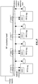
- Fig. 3 is a structural block diagram illustrating an RF read/write head according to embodiments of the present invention.
- the RF read/write head of embodiments of the present invention may include: a plurality of optical transmitters 310, a chip 320 and an RF antenna 330, where the RF antenna 330 is connected with the chip 320; the plurality of optical transmitters 310 are connected with the chip 320; and the chip 320 is configured to control an optical transmitter 310 corresponding to a designated RFID tag in the plurality of optical transmitters 310 to emit light so as to start the designated RFID tag when a read/write operation is carried out on the designated RFID tag in a plurality of RFID tags, and is also configured to carry out a read/write operation on the designated RFID tag.
- the RF read/write head may include only one RF antenna 330. Through the preferable implementation manner, it is unnecessary to set one RF antenna for each RFID tag, so that cost is reduced.
- a plurality of RF antennas 330 may be arranged; and, in order to avoid mutual interference, a certain distance is preferably kept among the plurality of RF antennas 330.
- the optical transmitters 310 may be LEDs, but not limited thereto.
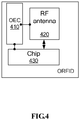
- Fig. 4 is a structural block diagram illustrating a passive RFID tag according to embodiments of the present invention.
- the passive RFID tag of embodiments of the present invention mainly includes: an OEC 410, an RF antenna 420 and a chip 430, where the OEC 410 is connected with the chip 430 and the RF antenna 420 and is configured to convert optical energy transmitted by an RF read/write head into electrical energy and supply power to the chip 430 and the RF antenna 420; the RF antenna 420 is connected with the chip 430; and the chip 430 is configured to store tag information and respond to a read/write operation of the RF read/write head.
- Fig. 5 is a schematic diagram illustrating an RF tag identification system according to embodiments of the present invention.
- the system includes: a plurality of passive RFID tags 1 and an RF read/write head 2, where with reference to Fig. 4 , each passive RFID tag 1 includes: an OEC, an RF antenna and a chip, where the OEC is connected with the chip and the RF antenna and is configured to convert optical energy transmitted by the RF read/write head into electrical energy and supply power to the chip and the RF antenna; and the chip is configured to store tag information and respond to a read/write operation of the RF read/write head 2; and with reference to Fig.
- the RF read/write head includes: a plurality of optical transmitters, a chip and an RF antenna, where the RF antenna is connected with the chip; the plurality of optical transmitters are connected with the chip; and the chip is configured to control an optical transmitter corresponding to a designated RFID tag in the plurality of optical transmitters to emit light so as to start the designated RFID tag when a read/write operation is carried out on the designated RFID tag in the plurality of RFID tags; and is also configured to carry out the read/write operation on the designated RFID tag.
- the RF read/write head 2 may include only one RF antenna.
- the optical transmitter may be an LED, but not limited thereto.
- the passive RFID tags 1 and the RF read/write head 2 are as described with reference to embodiment I and embodiment II and are not repeated here.
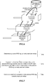
- Fig. 6 is a schematic diagram illustrating optical fiber connection heads and an optical fiber wiring apparatus according to embodiments of the present invention.
- each optical fiber connection head is provided with a passive RFID tag of embodiment II.
- the optical fiber wiring apparatus is provided with an RF read/write head of embodiment I, where the wiring apparatus includes a plurality of connection ports, each of which is configured to be connected with the optical fiber connection head in a pluggable manner; and a plurality of optical transmitters of the RFID head are arranged at positions that the optical fiber connection heads are respectively in alignment to the corresponding passive RFID tags on the optical fiber connection heads when the plurality of optical fiber connection heads are inserted into the plurality of connection ports.
- Fig. 7 is a flow chart illustrating a read/write method of an RFID tag system according to embodiments of the present invention.
- the RFID tag system includes an RF read/write head of embodiment I and a plurality of passive RFID tags of embodiment II. As shown in Fig. 7 , the method includes step S702 to step S706.
- step S702 a passive RFID tag currently read and written is determined.
- step S704 an optical transmitter corresponding to the passive RFID tag currently read and written in the RF read/write head is controlled to emit light, so as to supply power to the passive RFID tag currently read and written.
- step S706 a read/write operation is carried out on the passive RFID tag currently read and written.
- the above step S706 may include: sending an inquiry instruction to the passive RFID tag currently read and written, where the inquiry instruction is configured to inquire a state of the passive RFID tag currently read and written; and receiving a first state sent by the passive RFID tag currently read and written.
- the above state may be tag information and the like.
- the tag information may include identity information and position information.
- the method may further include: judging the above first state; and distributing tag information to the passive RFID tag currently read and written when the first state indicates that the passive RFID tag currently read and written is blank.
- the method may further include: judging the above first state; and requesting the passive RFID tag currently read and written to report its tag information when the first state indicates that the passive RFID tag currently read and written has tag information.
- the method may further include: receiving tag information reported by the passive RFID tag currently read and written; judging whether the received tag information meets a preset condition; and distributing new tag information to the passive RFID tag currently read and written when the received tag information does not meet the preset condition.
- the method may further include: closing the optical transmitter corresponding to the passive RFID tag currently read and written in the RF read/write head; and carrying out read/write operations on other passive RFID tags in the plurality of passive RFID tags.
- Fig. 8 is a structural block diagram illustrating a read/write apparatus of an RFID tag system according to embodiments of the present invention.
- the apparatus includes: a determination module 810, configured to determine a passive RFID tag currently read and written; a control module 820, configured to control an optical transmitter corresponding to the passive RFID tag currently read and written in the RF read/write head to emit light so as to supply power to the passive RFID tag currently read and written; and a read/write module 830, configured to carry out a read/write operation on the passive RFID tag currently read and written.
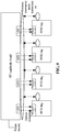
- Fig. 9 is a schematic diagram illustrating a preferable RFID system according to embodiments of the present invention. As shown in Fig. 9 , the system includes: an RF read/write head and a plurality of passive RFID tags.
- the RF read/write head is composed of a plurality of optical transmitters, an RF antenna and a control chip.
- the RF read/write head is an active device, may transmit light through the optical transmitters to charge the passive RFID tags and may also transmit RF signals to the passive RFID tags so as to transmit instructions; the RF antenna of the RF read/write head may also be configured to receive data signals transmitted back from the passive RFID tags, and the control chip processes the data signals.
- a sequence that the tags receive and transmit the information is controlled by controlling transmission states of the optical transmitters (which are LEDs in the preferable implementation manner), namely, if information of a certain designated tag needs to be read and written, a corresponding optical transmitter above the corresponding tag is started so as to charge the tag; and, the optical transmitter is closed after the read/write operation is completed, while other tags are in a no power state as other optical transmitters are closed. Therefore, the other tags cannot receive or transmit signals.
- the optical transmitters which are LEDs in the preferable implementation manner
- All the passive RFID tags share one RF antenna of the RF read/write head, while a control part and a processing part (including the chip) of the RF read/write head are arranged at idle positions beside the RF antenna.
- One advantage of doing this is that there is no need to arrange a complete read/write head on each tag, thereby reducing cost and reducing technical difficulty in reducing volume of the RF read/write head; and a corresponding LED may be arranged in a space above the narrow tag, and the tags share one RF antenna, thereby reducing cost and installation difficulty.
- the passive RFID tag includes an OEC, an RF antenna and a chip.
- the OEC converts received optical energy into electrical energy and transmits the electrical energy to the RF antenna and the chip
- the RF antenna transmits a received signal to the chip
- the RF antenna is started as required to transmit a reply signal to the RF read/write head after the chip processes data.
- the passive RFID tags are passive, firstly, the RF read/write head emits light to charge the passive RFID tags; then the RF read/write head sends corresponding instructions to the passive RFID tags; the passive RFID tags transmit corresponding replies by own RF antenna after receiving the instructions; and the read/write head processes the replies after receiving them.
- the read/write head informs the passive RFID tags of having received and ending if information is sufficient; and if the information is insufficient, the read/write head further sends inquiry instructions, and the passive RFID tags further send replies as required, and the process would not stop until the read/write head is satisfied.
- the read/write head is in non-contact with the passive RFID tags, but a distance between the read/write head and the passive RFID tags is very short and is generally limited to be very short. The distance may be limited to be within 1 cm in an application in an intelligent ODN, and data transmission between the read/write head and the passive RFID tags is realized through a video wireless communication point-to-point (P2P) technology.
- P2P video wireless communication point
- read/write for tag information is initiated by a chip in an RF read/write head.
- Passive RFID tags mainly store identity information and position information. These information are assigned by the RF read/write head and may also be modified by the RF read/write head.
- a working power supply of the passive RFID tags comes from their OECs by optical conversion, the passive RFID tags are charged by the RF read/write head, and the RF read/write head can control a starting or closing state of optical transmitters above the passive RFID tags so as to determine corresponding tags to read information.
- the RF read/write head is an active device and includes a plurality of optical transmitters, an RF antenna and a chip, where the optical transmitters are generally LEDs and have an effect of charging the passive RFID tags.
- the RF antenna has an effect of transmitting instructions to the passive RFID tags, and receiving signals sent by the passive RFID tags.
- the chip may receive an instruction of an external network manager, start read/write for the passive RFID tags, assign identity information and position information to blank passive RFID tags, read and compare passive RFID tags already have identity information, and modify corresponding information for the passive RFID tags.
- the control chip may start information transmission and reading for a certain passive RFID tag according to a starting or closing state of the LED, and finally, the read/write head transmits relevant information to the network manager or a control center for storing.
- the passive RFID tag is passive and includes an OEC, an RF antenna and a chip, where the OEC receives light of the RF read/write head and converts the light into a power supply to be used by the RF antenna and the chip; the RF antenna converts the received instruction of the RF read/write head into an electrical signal and transmits the electrical signal to the chip; and the chip can process the instruction and start the RF antenna to reply; the RF antenna sends a reply signal according to requirements of the chip, and meanwhile, the chip has a function of information storing.
- the OEC receives light of the RF read/write head and converts the light into a power supply to be used by the RF antenna and the chip
- the RF antenna converts the received instruction of the RF read/write head into an electrical signal and transmits the electrical signal to the chip
- the chip can process the instruction and start the RF antenna to reply; the RF antenna sends a reply signal according to requirements of the chip, and meanwhile, the chip has a function of information storing
- passive RFID tags are arranged on optical fiber connection heads.
- Corresponding LED optical transmitters are arranged above the tags, while a control part and a processing part (including a chip and the like) of an RF read/write head are arranged at idle positions of a device, and all the tags share one RF antenna of the RF read/write head. It indicates that an optical fiber is already in a connection state when the optical fiber connection heads are inserted into a connecting box, and at this moment, the tags are just below the optical transmitters of the RF read/write head.
- the read/write head receives an instruction of a network manager or a control center and carries out read/write on the tag, and the chip starts a read/write process, in which firstly the read/write head opens the LED corresponding to the passive RFID tag to charge the passive RFID tag, and then following test steps are started to be executed.
- step 1 an inquiry instruction, such as a state of the tag, is transmitted to the passive RFID tag.
- step 2 the passive RFID tag replies a current state, such as a blank state or a state of having identity information.
- step 3 the read/write head distributes one piece of identity information to the passive RFID tag if the tag has blank identity information; and the read/write head requires the passive RFID tag to report identity information if the passive RFID tag has right identity information.
- step 4 the passive RFID tag reports own current identity information after completing the execution.
- step 5 the read/write head verifies the identity information, and re-assigns new identity information to the passive RFID tag if the identity information does not meet requirements; the passive RFID tag repeats step 4; the read/write head re-assesses the information, and steps 3, 4 and 5 are repeated if the read/write head is not satisfied; and the read/write head sends an instruction of ending if information fed back meets requirements.
- step 6 the passive RFID tag replies ending and confirmation after receiving the ending instruction.
- step 7 the read/write head closes the LED after receiving the reply; and in step 8, the read/write head opens an LED corresponding to another passive RFID tag, and steps 1-7 are repeated.
- the RF antenna of the passive RFID tag does not need to consider the problem of power supply. Therefore, the function of the antenna recovers to the RF transmitting and receiving instincts; the antenna can be designed to be smaller, thereby greatly reducing the size and the volume of the tag; the size of the corresponding RF read/write head may also not need to be considered; only one LED optical transmitter needs to be arranged above the tag; meanwhile, the RF antenna and other parts are used in common, thereby greatly reducing the cost and overcoming the problem of limiting an application of the pure RFID as the pure RFID cannot be made to be small; and the passive RFID tag can solve the problem of identification of the dense optical connection heads.
- the read/write head can emit light to charge the tag only when the read/write head carries out read/write. In this way, the problem of supplying power by mistake to the adjacent tags does not exist, while the adjacent tags do not have enough power to support signal reception and transmission due to no irradiation of the light, therefore, the possibility of misjudgment of the read/write head as adjacent pure RFID tags compete to send signals is also avoided.
- all the above modules or steps of the present invention may be realized by a universal calculating apparatus and may be centralized on a single calculating apparatus or may be distributed on a network formed by a plurality of calculating apparatus.
- all the above modules or steps of the present invention may be realized by an executable program code of the calculating apparatus, so that all the above modules or steps of the present invention may be stored in a storing apparatus and then executed by the calculating apparatus.
- the shown or described steps may be executed according to a sequence different from the sequence here, or steps are respectively made into a plurality of integrated circuit modules, or a plurality of modules or steps in all the above modules or steps are made into a single integrated circuit module to realize. In this way, the present invention is not limited to a combination of any specific hardware and software.
- the passive RFID tag, the RF read/write head and the RFID system have following beneficial effects: firstly, the RF antenna of the passive RFID tag does not need to consider the problem of power supply, and the antenna can be designed to be smaller, thereby greatly reducing the size and the volume of the tag; the size of the corresponding RF read/write head may also not need to be considered; only one LED optical transmitter needs to be arranged above the tag; and meanwhile, the RF antenna and other parts are shared, thereby greatly reducing the cost.
- the passive RFID tag can solve the problem of identification of the dense optical connection heads.
- the read/write head can emit light to charge the tag only when the read/write head carries out read/write. In this way, the problem of supplying power by mistake to the adjacent tags does not exist, while the adjacent tags do not have enough power to support signal reception and transmission due to no irradiation of the light, therefore, the possibility of misjudgment of the read/write head as adjacent pure RFID tags compete to send signals is also avoided.
Abstract
Description
- The present invention relates to the field of communications, and in particular relates to a passive radio frequency identification (RFID) tag, a radio frequency (RF) read/write head and an RFID system.
- With maturity and development of optical fiber communication technologies and constant promotion of a modem information society for network demands, an optical fiber network has replaced a copper wire communication network, and the optical fiber network nearly covers all communication networks from a core network and a bearer network to an access network and then a fiber to the home (FTTH). A large number of optical fibers and connection points exist in the overall optical fiber network, so how to distinguish these optical fibers and connection conditions of the optical fibers becomes time-consuming and energy-wasting for operators. Therefore, in order to improve working efficiency and reduce working intensity, an intelligent tag is added to each optical connection point, then a read/write head automatically reads the tag, and relevant data are reported to a network manager, so that detection automation of the optical fiber connection points gradually becomes a consensus, thereby realizing a visible and manageable optical fiber network.
- In an intelligent optical distribution network (ODN), a tag and a read/write head are added to each optical connection head, so as to enable the intelligent ODN to automatically report a connection state of the intelligent ODN, i.e., intelligentization. China Communications Standards Association (CCSA) has formulated a series of corresponding standards for the intelligent ODN, and a corresponding industrial chain begins to form.
- Currently, two tag technologies are mainly adopted in the intelligent ODN. One of the technologies is a contact-type tag technology, which typically includes 1-Wire interface or an Electrically Erasable Programmable Read-only Memory (EEPROM) interface. As shown in
Fig. 1 , a tag needs to be powered. The contact-type tag technology proposes higher requirements for structural design and reliability of the tag. Meanwhile, the contact-type tag technology is not flexible enough due to physical connection in some rebuilding scenes. The other of the technologies is a non-contact-type tag technology, which typically includes an RFID technology. As shown inFig. 2 , due to working principle of the RFID technology, namely, magnetic lines are cut to generate induction current, a coil of the RFID technology is required to have a certain working area so as to generate enough induction current for driving a chip to work normally. Next, a working coil of the read/write head is also required to have a certain working area, causing that adjacent RFIDs are also induced and causing mutual interference. Therefore, this technology is unsuitable for a working environment with optical nodes of dense optical fiber connection heads. - In view of this, a read/write technology is required so that a tag can not only maintain non-contact-type read/write, but also meet other tags required by optical nodes of dense optical fiber connection heads.
- Embodiments of the present invention provide a passive RFID tag, an RF read/write head and an RFID system, so as to at least solve the problem that a contact-type tag technology and RFID tags can not meet the requirements for dense scenes in relevant technologies.
- According to one aspect of the present invention, provided is an RF read/write head, including: a plurality of optical transmitters, a chip and an RF antenna, where the RF antenna is connected with the chip; the plurality of optical transmitters are connected with the chip; and the chip is configured to control an optical transmitter corresponding to a designated RFID tag in the plurality of optical transmitters to emit light so as to start the designated RFID tag when a read/write operation is carried out on the designated RFID tag in the plurality of RFID tags; and carry out the read/write operation on the designated RFID tag.
- Preferably, the RF read/write head includes one RF antenna.
- Preferably, each of the optical transmitters is a light emitting diode (LED).
- According to another aspect of the present invention, provided is a passive RFID tag, including: an optical to electrical converter (OEC), an RF antenna and a chip, where the OEC is connected with the chip and the RF antenna and is configured to convert optical energy transmitted by an RF read/write head into electrical energy and supply power to the chip and the RF antenna; the RF antenna is connected with the chip; and the chip is configured to store tag information and respond to a read/write operation of the RF read/write head.
- According to still another aspect of the present invention, provided is an RF tag identification system, including a plurality of passive RFID tags and an RF read/write head, where
each of the passive RFID tag includes: an OEC, a first RF antenna and a first chip, where the OEC is connected with the first chip and the first RF antenna and is configured to convert optical energy transmitted by the RF read/write head into electrical energy and supply power to the first chip and the first RF antenna; and the first chip is configured to store tag information and respond to a read/write operation of the RF read/write head;
the RF read/write head includes: a plurality of optical transmitters, a second chip and a second RF antenna, where the second RF antenna is connected with the second chip; the plurality of optical transmitters are connected with the second chip; and the second chip is configured to control an optical transmitter corresponding to a designated RFID tag in the plurality of optical transmitters to emit light so as to start the designated RFID tag when a read/write operation is carried out on the designated RFID tag in the plurality of RFID tags; and carry out the read/write operation on the designated RFID tag. - Preferably, the RF read/write head includes one second RF antenna.
- Preferably, each of the optical transmitters is an LED.
- According to another aspect of the present invention, an optical fiber connection head is provided, and the optical fiber connection head is provided with the above passive RFID tags of the present invention.
- According to still another aspect of the present invention, an optical fiber wiring apparatus is provided, and the optical fiber wiring apparatus is provided with the above RF read/write head of the present invention, where the wiring apparatus includes a plurality of connection ports, and each connection port is configured to be connected with the above optical fiber connection head of the present invention in a pluggable manner; and a plurality of optical transmitters of the RF read/write head are arranged at positions that the optical transmitters are respectively in alignment to the corresponding passive RFID tags on the optical fiber connection heads when the plurality of optical fiber connection heads are inserted into the plurality of connection ports.
- According to another aspect of the present invention, a read/write method of an RFID tag system is provided. The RFID tag system includes: the above RF read/write head of the present invention and the plurality of above passive RFID tags of the present invention. The method includes: determining the passive RFID tag currently read and written; controlling the optical transmitter corresponding to the passive RFID tag currently read and written in the RF read/write head to emit light, so as to supply power to the passive RFID tag currently read and written; and carrying out a read/write operation on the passive RFID tag currently read and written.
- Preferably, the carrying out the read/write operation on the passive RFID tag currently read and written, includes: sending an inquiry instruction to the passive RFID tag currently read and written, where the inquiry instruction is configured to inquire a state of the passive RFID tag currently read and written; and receiving a first state sent by the passive RFID tag currently read and written.
- Preferably, the above method further includes: judging the first state; and distributing tag information to the passive RFID tag currently read and written when the first state indicates that the passive RFID tag currently read and written is blank.
- Preferably, the above method further includes: judging the first state; and requesting the passive RFID tag currently read and written to report its tag information when the first state indicates that the passive RFID tag currently read and written has the tag information.
- Preferably, the above method further includes: receiving the tag information reported by the passive RFID tag currently read and written; judging whether the received tag information meets a preset condition; and distributing new tag information to the passive RFID tag currently read and written when the received tag information does not meet the preset condition.
- Preferably, after carrying out the read/write operation on the passive RFID tag currently read and written, the method further includes: closing an optical transmitter corresponding to the passive RFID tag currently read and written in the RF read/write head; and carrying out read/write operations on other passive RFID tags in the plurality of passive RFID tags.
- According to still another aspect of the present invention, a read/write apparatus of an RFID tag system is provided. The RFID tag system includes the above RF read/write head of the present invention and the plurality of above passive RFID tags of the present invention. The apparatus includes: a determination module, configured to determine the passive RFID tag currently read and written; a control module, configured to control an optical transmitter corresponding to the passive RFID tag currently read and written in the RF read/write head to emit light, so as to supply power to the passive RFID tag currently read and written; and a read/write module, configured to carry out a read/write operation on the passive RFID tag currently read and written.
- Through embodiments of the present invention, non-contact-type RFID is realized, and mutual interference of the RFID tags in dense scenes is reduced or avoided.
- Drawings described here are used for providing further understanding for the present invention and form a part of the present application. Exemplary embodiments of the present invention and the description for the exemplary embodiments are used for explaining the present invention, rather than limiting the present invention. In the drawings:
-
Fig. 1 is a schematic diagram illustrating a contact-type tag technology according to a relevant technology; -
Fig. 2 is a schematic diagram illustrating an RFID technology according to a relevant technology; -
Fig. 3 is a structural block diagram illustrating an RF read/write head according to embodiments of the present invention; -
Fig. 4 is a structural block diagram illustrating a passive RFID tag according to embodiments of the present invention; -
Fig. 5 is a schematic diagram illustrating an RF tag identification system according to embodiments of the present invention; -
Fig. 6 is a schematic diagram illustrating optical fiber connection heads and an optical fiber wiring apparatus according to embodiments of the present invention; -
Fig. 7 is a flow chart illustrating a read/write method of an RFID tag system according to embodiments of the present invention; -
Fig. 8 is a structural block diagram illustrating a read/write apparatus of an RFID tag system according to embodiments of the present invention; and -
Fig. 9 is a schematic diagram illustrating a preferable RFID system according to embodiments of the present invention. - The present invention is described below in detail with reference to drawings and in combination with embodiments. It should be noted that embodiments in the present application can be combined with the features in embodiments under the condition of no conflict.
- The following embodiments provide a non-contact-type tag solution, where RFID tags are charged by a technology of an OEC, and an RFID tag with the OEC is called as an optical RFID tag for short and also called as a passive RFID tag.
-
Fig. 3 is a structural block diagram illustrating an RF read/write head according to embodiments of the present invention. As shown inFig. 3 , the RF read/write head of embodiments of the present invention may include: a plurality ofoptical transmitters 310, a chip 320 and anRF antenna 330, where theRF antenna 330 is connected with the chip 320; the plurality ofoptical transmitters 310 are connected with the chip 320; and the chip 320 is configured to control anoptical transmitter 310 corresponding to a designated RFID tag in the plurality ofoptical transmitters 310 to emit light so as to start the designated RFID tag when a read/write operation is carried out on the designated RFID tag in a plurality of RFID tags, and is also configured to carry out a read/write operation on the designated RFID tag. - In one preferable implementation manner of embodiments of the present invention, the RF read/write head may include only one
RF antenna 330. Through the preferable implementation manner, it is unnecessary to set one RF antenna for each RFID tag, so that cost is reduced. - Of course, in embodiments of the present invention, a plurality of
RF antennas 330 may be arranged; and, in order to avoid mutual interference, a certain distance is preferably kept among the plurality ofRF antennas 330. - In one preferable implementation manner of embodiments of the present invention, the
optical transmitters 310 may be LEDs, but not limited thereto. -
Fig. 4 is a structural block diagram illustrating a passive RFID tag according to embodiments of the present invention. As shown inFig. 4 , the passive RFID tag of embodiments of the present invention mainly includes: anOEC 410, anRF antenna 420 and achip 430, where theOEC 410 is connected with thechip 430 and theRF antenna 420 and is configured to convert optical energy transmitted by an RF read/write head into electrical energy and supply power to thechip 430 and theRF antenna 420; theRF antenna 420 is connected with thechip 430; and thechip 430 is configured to store tag information and respond to a read/write operation of the RF read/write head. -
Fig. 5 is a schematic diagram illustrating an RF tag identification system according to embodiments of the present invention. As shown inFig. 5 , the system includes: a plurality of passive RFID tags 1 and an RF read/write head 2, where
with reference toFig. 4 , each passive RFID tag 1 includes: an OEC, an RF antenna and a chip, where the OEC is connected with the chip and the RF antenna and is configured to convert optical energy transmitted by the RF read/write head into electrical energy and supply power to the chip and the RF antenna; and the chip is configured to store tag information and respond to a read/write operation of the RF read/write head 2; and
with reference toFig. 3 , the RF read/write head includes: a plurality of optical transmitters, a chip and an RF antenna, where the RF antenna is connected with the chip; the plurality of optical transmitters are connected with the chip; and the chip is configured to control an optical transmitter corresponding to a designated RFID tag in the plurality of optical transmitters to emit light so as to start the designated RFID tag when a read/write operation is carried out on the designated RFID tag in the plurality of RFID tags; and is also configured to carry out the read/write operation on the designated RFID tag. - In one preferable implementation manner of embodiments of the present invention, the RF read/write head 2 may include only one RF antenna.
- In one preferable implementation manner of embodiments of the present invention, the optical transmitter may be an LED, but not limited thereto.
- The passive RFID tags 1 and the RF read/write head 2 are as described with reference to embodiment I and embodiment II and are not repeated here.
-
Fig. 6 is a schematic diagram illustrating optical fiber connection heads and an optical fiber wiring apparatus according to embodiments of the present invention. As shown inFig. 6 , each optical fiber connection head is provided with a passive RFID tag of embodiment II. The optical fiber wiring apparatus is provided with an RF read/write head of embodiment I, where the wiring apparatus includes a plurality of connection ports, each of which is configured to be connected with the optical fiber connection head in a pluggable manner; and a plurality of optical transmitters of the RFID head are arranged at positions that the optical fiber connection heads are respectively in alignment to the corresponding passive RFID tags on the optical fiber connection heads when the plurality of optical fiber connection heads are inserted into the plurality of connection ports. -
Fig. 7 is a flow chart illustrating a read/write method of an RFID tag system according to embodiments of the present invention. The RFID tag system includes an RF read/write head of embodiment I and a plurality of passive RFID tags of embodiment II. As shown inFig. 7 , the method includes step S702 to step S706. - In step S702, a passive RFID tag currently read and written is determined.
- In step S704, an optical transmitter corresponding to the passive RFID tag currently read and written in the RF read/write head is controlled to emit light, so as to supply power to the passive RFID tag currently read and written.
- In step S706, a read/write operation is carried out on the passive RFID tag currently read and written.
- In one implementation manner of embodiments of the present invention, the above step S706 may include: sending an inquiry instruction to the passive RFID tag currently read and written, where the inquiry instruction is configured to inquire a state of the passive RFID tag currently read and written; and receiving a first state sent by the passive RFID tag currently read and written. Preferably, the above state may be tag information and the like. The tag information may include identity information and position information.
- In one implementation manner of embodiments of the present invention, the method may further include: judging the above first state; and distributing tag information to the passive RFID tag currently read and written when the first state indicates that the passive RFID tag currently read and written is blank.
- In one implementation manner of embodiments of the present invention, the method may further include: judging the above first state; and requesting the passive RFID tag currently read and written to report its tag information when the first state indicates that the passive RFID tag currently read and written has tag information.
- In one implementation manner of embodiments of the present invention, the method may further include: receiving tag information reported by the passive RFID tag currently read and written; judging whether the received tag information meets a preset condition; and distributing new tag information to the passive RFID tag currently read and written when the received tag information does not meet the preset condition.
- In one implementation manner of embodiments of the present invention, after carrying out the read/write operation on the passive RFID tag currently read and written, the method may further include: closing the optical transmitter corresponding to the passive RFID tag currently read and written in the RF read/write head; and carrying out read/write operations on other passive RFID tags in the plurality of passive RFID tags.
-
Fig. 8 is a structural block diagram illustrating a read/write apparatus of an RFID tag system according to embodiments of the present invention. The apparatus includes: adetermination module 810, configured to determine a passive RFID tag currently read and written; acontrol module 820, configured to control an optical transmitter corresponding to the passive RFID tag currently read and written in the RF read/write head to emit light so as to supply power to the passive RFID tag currently read and written; and a read/write module 830, configured to carry out a read/write operation on the passive RFID tag currently read and written. - Preferable implementation manners of embodiments of the present invention are described below.
-
Fig. 9 is a schematic diagram illustrating a preferable RFID system according to embodiments of the present invention. As shown inFig. 9 , the system includes: an RF read/write head and a plurality of passive RFID tags. - The RF read/write head is composed of a plurality of optical transmitters, an RF antenna and a control chip. With reference to a basic architecture diagram in
Fig. 3 , the RF read/write head is an active device, may transmit light through the optical transmitters to charge the passive RFID tags and may also transmit RF signals to the passive RFID tags so as to transmit instructions; the RF antenna of the RF read/write head may also be configured to receive data signals transmitted back from the passive RFID tags, and the control chip processes the data signals. In order to avoid the situation that the plurality of passive RFID tags simultaneously transmit information which causing confusion when the RF read/write head receives the information, a sequence that the tags receive and transmit the information is controlled by controlling transmission states of the optical transmitters (which are LEDs in the preferable implementation manner), namely, if information of a certain designated tag needs to be read and written, a corresponding optical transmitter above the corresponding tag is started so as to charge the tag; and, the optical transmitter is closed after the read/write operation is completed, while other tags are in a no power state as other optical transmitters are closed. Therefore, the other tags cannot receive or transmit signals. - All the passive RFID tags share one RF antenna of the RF read/write head, while a control part and a processing part (including the chip) of the RF read/write head are arranged at idle positions beside the RF antenna. One advantage of doing this is that there is no need to arrange a complete read/write head on each tag, thereby reducing cost and reducing technical difficulty in reducing volume of the RF read/write head; and a corresponding LED may be arranged in a space above the narrow tag, and the tags share one RF antenna, thereby reducing cost and installation difficulty.
- The passive RFID tag includes an OEC, an RF antenna and a chip. With reference to a basic architecture diagram in
Fig. 4 , firstly, the OEC converts received optical energy into electrical energy and transmits the electrical energy to the RF antenna and the chip, the RF antenna transmits a received signal to the chip, and the RF antenna is started as required to transmit a reply signal to the RF read/write head after the chip processes data. - As the passive RFID tags are passive, firstly, the RF read/write head emits light to charge the passive RFID tags; then the RF read/write head sends corresponding instructions to the passive RFID tags; the passive RFID tags transmit corresponding replies by own RF antenna after receiving the instructions; and the read/write head processes the replies after receiving them. The read/write head informs the passive RFID tags of having received and ending if information is sufficient; and if the information is insufficient, the read/write head further sends inquiry instructions, and the passive RFID tags further send replies as required, and the process would not stop until the read/write head is satisfied. The read/write head is in non-contact with the passive RFID tags, but a distance between the read/write head and the passive RFID tags is very short and is generally limited to be very short. The distance may be limited to be within 1 cm in an application in an intelligent ODN, and data transmission between the read/write head and the passive RFID tags is realized through a video wireless communication point-to-point (P2P) technology.
- As shown in
Fig. 9 , read/write for tag information is initiated by a chip in an RF read/write head. Passive RFID tags mainly store identity information and position information. These information are assigned by the RF read/write head and may also be modified by the RF read/write head. A working power supply of the passive RFID tags comes from their OECs by optical conversion, the passive RFID tags are charged by the RF read/write head, and the RF read/write head can control a starting or closing state of optical transmitters above the passive RFID tags so as to determine corresponding tags to read information. - With reference to a structure of the RF read/write head in
Fig. 3 , the RF read/write head is an active device and includes a plurality of optical transmitters, an RF antenna and a chip, where the optical transmitters are generally LEDs and have an effect of charging the passive RFID tags. The RF antenna has an effect of transmitting instructions to the passive RFID tags, and receiving signals sent by the passive RFID tags. The chip may receive an instruction of an external network manager, start read/write for the passive RFID tags, assign identity information and position information to blank passive RFID tags, read and compare passive RFID tags already have identity information, and modify corresponding information for the passive RFID tags. The control chip may start information transmission and reading for a certain passive RFID tag according to a starting or closing state of the LED, and finally, the read/write head transmits relevant information to the network manager or a control center for storing. - With reference to a structure of the passive RFID tag in
Fig. 4 , the passive RFID tag is passive and includes an OEC, an RF antenna and a chip, where the OEC receives light of the RF read/write head and converts the light into a power supply to be used by the RF antenna and the chip; the RF antenna converts the received instruction of the RF read/write head into an electrical signal and transmits the electrical signal to the chip; and the chip can process the instruction and start the RF antenna to reply; the RF antenna sends a reply signal according to requirements of the chip, and meanwhile, the chip has a function of information storing. - With reference to
Fig. 6 , passive RFID tags are arranged on optical fiber connection heads. Corresponding LED optical transmitters are arranged above the tags, while a control part and a processing part (including a chip and the like) of an RF read/write head are arranged at idle positions of a device, and all the tags share one RF antenna of the RF read/write head. It indicates that an optical fiber is already in a connection state when the optical fiber connection heads are inserted into a connecting box, and at this moment, the tags are just below the optical transmitters of the RF read/write head. - When the tag is read and written, a specific working process is described below.
- Firstly, the read/write head receives an instruction of a network manager or a control center and carries out read/write on the tag, and the chip starts a read/write process, in which firstly the read/write head opens the LED corresponding to the passive RFID tag to charge the passive RFID tag, and then following test steps are started to be executed.
- In step 1, an inquiry instruction, such as a state of the tag, is transmitted to the passive RFID tag.
- In step 2, the passive RFID tag replies a current state, such as a blank state or a state of having identity information.
- In step 3, the read/write head distributes one piece of identity information to the passive RFID tag if the tag has blank identity information; and the read/write head requires the passive RFID tag to report identity information if the passive RFID tag has right identity information.
- In step 4, the passive RFID tag reports own current identity information after completing the execution.
- In step 5, the read/write head verifies the identity information, and re-assigns new identity information to the passive RFID tag if the identity information does not meet requirements; the passive RFID tag repeats step 4; the read/write head re-assesses the information, and steps 3, 4 and 5 are repeated if the read/write head is not satisfied; and
the read/write head sends an instruction of ending if information fed back meets requirements. - In step 6, the passive RFID tag replies ending and confirmation after receiving the ending instruction.
- In step 7, the read/write head closes the LED after receiving the reply; and
in step 8, the read/write head opens an LED corresponding to another passive RFID tag, and steps 1-7 are repeated. - From the above descriptions, it can be seen that the present invention achieves following technical effects.
- Compared to a pure RFID, firstly, the RF antenna of the passive RFID tag does not need to consider the problem of power supply. Therefore, the function of the antenna recovers to the RF transmitting and receiving instincts; the antenna can be designed to be smaller, thereby greatly reducing the size and the volume of the tag; the size of the corresponding RF read/write head may also not need to be considered; only one LED optical transmitter needs to be arranged above the tag; meanwhile, the RF antenna and other parts are used in common, thereby greatly reducing the cost and overcoming the problem of limiting an application of the pure RFID as the pure RFID cannot be made to be small; and the passive RFID tag can solve the problem of identification of the dense optical connection heads. Secondly, as the tag is charged by the light, the read/write head can emit light to charge the tag only when the read/write head carries out read/write. In this way, the problem of supplying power by mistake to the adjacent tags does not exist, while the adjacent tags do not have enough power to support signal reception and transmission due to no irradiation of the light, therefore, the possibility of misjudgment of the read/write head as adjacent pure RFID tags compete to send signals is also avoided.
- Apparently, those skilled in the art should understand that all the above modules or steps of the present invention may be realized by a universal calculating apparatus and may be centralized on a single calculating apparatus or may be distributed on a network formed by a plurality of calculating apparatus. Alternatively, all the above modules or steps of the present invention may be realized by an executable program code of the calculating apparatus, so that all the above modules or steps of the present invention may be stored in a storing apparatus and then executed by the calculating apparatus. Moreover, under some conditions, the shown or described steps may be executed according to a sequence different from the sequence here, or steps are respectively made into a plurality of integrated circuit modules, or a plurality of modules or steps in all the above modules or steps are made into a single integrated circuit module to realize. In this way, the present invention is not limited to a combination of any specific hardware and software.
- The above descriptions are only preferable embodiments of the present invention, rather than a limit to the present invention. Those skilled in the art should understand that the present invention may have a variety of modifications and changes. Any modification, equivalent replacement, improvement and the like made within the spirit and the principle of the present invention shall be included in the protection scope of the present invention.
- As mentioned above, the passive RFID tag, the RF read/write head and the RFID system provided by embodiments of the present invention have following beneficial effects: firstly, the RF antenna of the passive RFID tag does not need to consider the problem of power supply, and the antenna can be designed to be smaller, thereby greatly reducing the size and the volume of the tag; the size of the corresponding RF read/write head may also not need to be considered; only one LED optical transmitter needs to be arranged above the tag; and meanwhile, the RF antenna and other parts are shared, thereby greatly reducing the cost. However, the passive RFID tag can solve the problem of identification of the dense optical connection heads. Secondly, as the tag is charged by the light, the read/write head can emit light to charge the tag only when the read/write head carries out read/write. In this way, the problem of supplying power by mistake to the adjacent tags does not exist, while the adjacent tags do not have enough power to support signal reception and transmission due to no irradiation of the light, therefore, the possibility of misjudgment of the read/write head as adjacent pure RFID tags compete to send signals is also avoided.
Claims (16)
- An radio frequency RF read/write head, comprising: a plurality of optical transmitters, a chip and an RF antenna, wherein
the RF antenna is connected with the chip;
the plurality of optical transmitters are connected with the chip; and
the chip is configured to control an optical transmitter corresponding to a designated radio frequency identification RFID tag in the plurality of optical transmitters to emit light so as to start the designated RFID tag when a read/write operation is carried out on the designated RFID tag in the plurality of RFID tags; and carry out the read/write operation on the designated RFID tag. - The RF read/write head according to claim 1, wherein the RF read/write head comprises one RF antenna.
- The RF read/write head according to claim 1, wherein each of the optical transmitters is an light emitting diode LED.
- A passive RFID tag, comprising: an optical to electrical converter OEC, an RF antenna and a chip, wherein
the OEC is connected with the chip and the RF antenna and is configured to convert optical energy transmitted by an RF read/write head into electrical energy and supply power to the chip and the RF antenna;
the RF antenna is connected with the chip; and
the chip is configured to store tag information and respond to a read/write operation of the RF read/write head. - An RF tag identification system, comprising: a plurality of passive RFID tags and an RF read/write head, wherein
each of the passive RFID tags comprises: an OEC, a first RF antenna and a first chip, wherein the OEC is connected with the first chip and the first RF antenna and is configured to convert optical energy transmitted by the RF read/write head into electrical energy and supply power to the first chip and the first RF antenna; and the first chip is configured to store tag information and respond to a read/write operation of the RF read/write head;
the RF read/write head comprises: a plurality of optical transmitters, a second chip and a second RF antenna, wherein the second RF antenna is connected with the second chip; the plurality of optical transmitters are connected with the second chip; and the second chip is configured to control an optical transmitter corresponding to a designated RFID tag in the plurality of optical transmitters to emit light so as to start the designated RFID tag when a read/write operation is carried out on the designated RFID tag in the plurality of RFID tags; and carry out the read/write operation on the designated RFID tag. - The RF tag identification system according to claim 5, wherein the RF read/write head comprises one second RF antenna.
- The RF tag identification system according to claim 5, wherein each of the optical transmitters is an LED.
- An optical fiber connection head, which is provided with the passive RFID tag according to claim 4.
- An optical fiber wiring apparatus, which is provided with the RF read/write head according to any of claims 1-3, wherein
the wiring apparatus comprises a plurality of connection ports, and each connection port is configured to be connected with the optical fiber connection head according to claim 8 in a pluggable manner; and
a plurality of optical transmitters of the RF read/write head are arranged at positions that the optical transmitters are respectively in alignment to the corresponding passive RFID tags on the optical fiber connection heads when the plurality of optical fiber connection heads are inserted into the plurality of connection ports. - A read/write method of an RFID tag system, wherein the RFID tag system comprises: the RF read/write head according to any of claims 1-3 and the plurality of passive RFID tags according to claim 4; the method comprises:determining the passive RFID tag currently read and written;controlling the optical transmitter corresponding to the passive RFID tag currently read and written in the RF read/write head to emit light, so as to supply power to the passive RFID tag currently read and written; andcarrying out a read/write operation on the passive RFID tag currently read and written.
- The method according to claim 5, wherein the carrying out the read/write operation on the passive RFID tag currently read and written, comprises:sending an inquiry instruction to the passive RFID tag currently read and written, wherein the inquiry instruction is configured to inquire a state of the passive RFID tag currently read and written; andreceiving a first state sent by the passive RFID tag currently read and written.
- The method according to claim 11, further comprising:judging the first state; anddistributing tag information to the passive RFID tag currently read and written when the first state indicates that the passive RFID tag currently read and written is blank.
- The method according to claim 11 or 12, further comprising:judging the first state; andrequesting the passive RFID tag currently read and written to report its tag information when the first state indicates that the passive RFID tag currently read and written has tag information.
- The method according to claim 13, further comprising:receiving tag information reported by the passive RFID tag currently read and written;judging whether the received tag information meets a preset condition; anddistributing new tag information to the passive RFID tag currently read and written when the received tag information does not meet the preset condition.
- The method according to claim 10, after carrying out the read/write operation on the passive RFID tag currently read and written, further comprising:closing an optical transmitter corresponding to the passive RFID tag currently read and written in the RF read/write head; andcarrying out read/write operations on other passive RFID tags in the plurality of passive RFID tags.
- A read/write apparatus of an RFID tag system, wherein the RFID tag system comprises the RF read/write head according to any of claims 1-3 and the plurality of passive RFID tags according to claim 4, wherein the apparatus comprises:a determination module, configured to determine the passive RFID tag currently read and written;a control module, configured to control an optical transmitter corresponding to the passive RFID tag currently read and written in the RF read/write head to emit light, so as to supply power to the passive RFID tag currently read and written; anda read/write module, configured to carry out a read/write operation on the passive RFID tag currently read and written.
Applications Claiming Priority (2)
| Application Number | Priority Date | Filing Date | Title |
|---|---|---|---|
| CN201410223544.4A CN105095928A (en) | 2014-05-23 | 2014-05-23 | Passive RFID tag, RF read-write head, and RFID system |
| PCT/CN2014/091810 WO2015176514A1 (en) | 2014-05-23 | 2014-11-20 | Passive radio frequency identification tag, radio frequency read/write head and radio frequency identification system |
Publications (3)
| Publication Number | Publication Date |
|---|---|
| EP3142047A1 true EP3142047A1 (en) | 2017-03-15 |
| EP3142047A4 EP3142047A4 (en) | 2018-02-21 |
| EP3142047B1 EP3142047B1 (en) | 2019-08-21 |
Family
ID=54553368
Family Applications (1)
| Application Number | Title | Priority Date | Filing Date |
|---|---|---|---|
| EP14892540.7A Active EP3142047B1 (en) | 2014-05-23 | 2014-11-20 | Passive radio frequency identification tag, radio frequency read/write head and radio frequency identification system |
Country Status (3)
| Country | Link |
|---|---|
| EP (1) | EP3142047B1 (en) |
| CN (1) | CN105095928A (en) |
| WO (1) | WO2015176514A1 (en) |
Families Citing this family (3)
| Publication number | Priority date | Publication date | Assignee | Title |
|---|---|---|---|---|
| WO2017118914A1 (en) * | 2016-01-08 | 2017-07-13 | Teslonix Inc. | Charging long-range radio frequency identification tags |
| CN108234024A (en) * | 2016-12-21 | 2018-06-29 | 中兴通讯股份有限公司 | ODN system and its method of work |
| DE112018004801T5 (en) | 2017-08-30 | 2020-06-18 | Cummins Filtration Ip, Inc. | LOCKING DEVICE FOR DETECTING ORIGINAL FILTERS |
Family Cites Families (7)
| Publication number | Priority date | Publication date | Assignee | Title |
|---|---|---|---|---|
| JP2003536302A (en) * | 2000-06-06 | 2003-12-02 | バッテル メモリアル インスティテュート | Telecommunications systems and methods |
| GB2410151A (en) * | 2004-01-15 | 2005-07-20 | Rf Tags Ltd | A radio frequency identification tag with means sensitive to light for controlling communication between rfid tag and reader |
| KR100936893B1 (en) * | 2008-01-04 | 2010-01-14 | 중앙대학교 산학협력단 | Method for identification of tags and anti-collision, and RFID tag using the same |
| WO2009113827A2 (en) * | 2008-03-12 | 2009-09-17 | 한국전자통신연구원 | Rfid interrogator retransmitting command depending on collision situation and control method thereof |
| CN101533460A (en) * | 2009-04-24 | 2009-09-16 | 清华大学 | System and method of radio frequency identification |
| CN104350508A (en) * | 2012-03-30 | 2015-02-11 | 泰科电子英国有限公司 | Rfid reader extender |
| CN103488967B (en) * | 2013-10-14 | 2016-08-10 | 张祖锋 | A kind of based on visible ray or the Cabinet administration system of infrared location and method |
-
2014
- 2014-05-23 CN CN201410223544.4A patent/CN105095928A/en active Pending
- 2014-11-20 WO PCT/CN2014/091810 patent/WO2015176514A1/en active Application Filing
- 2014-11-20 EP EP14892540.7A patent/EP3142047B1/en active Active
Also Published As
| Publication number | Publication date |
|---|---|
| EP3142047B1 (en) | 2019-08-21 |
| CN105095928A (en) | 2015-11-25 |
| EP3142047A4 (en) | 2018-02-21 |
| WO2015176514A1 (en) | 2015-11-26 |
Similar Documents
| Publication | Publication Date | Title |
|---|---|---|
| CN101647028B (en) | Method for establishing a wireless communication connection between an automation component and a mobile operating terminal | |
| US20070175995A1 (en) | RFID reader/writer | |
| CN201522715U (en) | Radio frequency identification reader | |
| CN102819518B (en) | A kind of radio-frequency (RF) identification bus system | |
| EP3147813A1 (en) | Reflection-type passive optical tag, optical read/write device and intelligent optical distribution network | |
| EP3142047B1 (en) | Passive radio frequency identification tag, radio frequency read/write head and radio frequency identification system | |
| CN102136056A (en) | Establishing a wireless communications bus and applications thereof | |
| US20170116441A1 (en) | Passive optical tag, optical read/write device and intelligent optical distribution network | |
| CN103053118B (en) | Hybrid architecture for radio frequency identification and packet radio communication | |
| US20150053758A1 (en) | Fiber management system and method thereof | |
| WO2015176479A1 (en) | Passive radio frequency identification tag, optical radio frequency read/write head and radio frequency identification system | |
| GB2536068A (en) | Method for configuring an electronic element in a lighting system, electronic element and configuring system | |
| US20120256005A1 (en) | Connection cable for the electrical or optical fiber connection of two system devices | |
| CN105357664A (en) | Wireless control system and data communication method thereof | |
| CN113965919B (en) | Information detection method and base station | |
| CN107886019B (en) | Cascade device and antenna cascade system | |
| CN112528688B (en) | Radio frequency tag control method, response method and device, storage medium, reader and radio frequency tag | |
| CN108172964B (en) | Indoor branch antenna with marking function | |
| CN110490016A (en) | A kind of radio frequency identification system | |
| KR20170099573A (en) | Smart label, apparatus and method for contorlling optical network using the same | |
| CN108960388A (en) | A kind of connecting detection system and method | |
| US7436307B2 (en) | Method and system for setting parameters of a field station in a communications network | |
| CN201540583U (en) | RFID smart antenna | |
| CN203405835U (en) | Indoor type RFID intelligent reader | |
| US8872630B2 (en) | Method and apparatus for cabinet asset management, and cabinet system |
Legal Events
| Date | Code | Title | Description |
|---|---|---|---|
| STAA | Information on the status of an ep patent application or granted ep patent |
Free format text: STATUS: THE INTERNATIONAL PUBLICATION HAS BEEN MADE |
|
| PUAI | Public reference made under article 153(3) epc to a published international application that has entered the european phase |
Free format text: ORIGINAL CODE: 0009012 |
|
| STAA | Information on the status of an ep patent application or granted ep patent |
Free format text: STATUS: REQUEST FOR EXAMINATION WAS MADE |
|
| 17P | Request for examination filed |
Effective date: 20161209 |
|
| AK | Designated contracting states |
Kind code of ref document: A1 Designated state(s): AL AT BE BG CH CY CZ DE DK EE ES FI FR GB GR HR HU IE IS IT LI LT LU LV MC MK MT NL NO PL PT RO RS SE SI SK SM TR |
|
| AX | Request for extension of the european patent |
Extension state: BA ME |
|
| DAX | Request for extension of the european patent (deleted) | ||
| A4 | Supplementary search report drawn up and despatched |
Effective date: 20180123 |
|
| RIC1 | Information provided on ipc code assigned before grant |
Ipc: G06K 17/00 20060101AFI20180117BHEP Ipc: G06K 7/00 20060101ALI20180117BHEP Ipc: G06K 7/10 20060101ALI20180117BHEP Ipc: G06K 19/07 20060101ALI20180117BHEP |
|
| GRAP | Despatch of communication of intention to grant a patent |
Free format text: ORIGINAL CODE: EPIDOSNIGR1 |
|
| STAA | Information on the status of an ep patent application or granted ep patent |
Free format text: STATUS: GRANT OF PATENT IS INTENDED |
|
| RIC1 | Information provided on ipc code assigned before grant |
Ipc: G06K 7/10 20060101ALI20190314BHEP Ipc: G06K 19/07 20060101ALI20190314BHEP Ipc: G06K 17/00 20060101AFI20190314BHEP Ipc: G06K 7/00 20060101ALI20190314BHEP |
|
| INTG | Intention to grant announced |
Effective date: 20190401 |
|
| GRAS | Grant fee paid |
Free format text: ORIGINAL CODE: EPIDOSNIGR3 |
|
| GRAA | (expected) grant |
Free format text: ORIGINAL CODE: 0009210 |
|
| STAA | Information on the status of an ep patent application or granted ep patent |
Free format text: STATUS: THE PATENT HAS BEEN GRANTED |
|
| AK | Designated contracting states |
Kind code of ref document: B1 Designated state(s): AL AT BE BG CH CY CZ DE DK EE ES FI FR GB GR HR HU IE IS IT LI LT LU LV MC MK MT NL NO PL PT RO RS SE SI SK SM TR |
|
| REG | Reference to a national code |
Ref country code: GB Ref legal event code: FG4D |
|
| REG | Reference to a national code |
Ref country code: CH Ref legal event code: EP |
|
| REG | Reference to a national code |
Ref country code: DE Ref legal event code: R096 Ref document number: 602014052341 Country of ref document: DE |
|
| REG | Reference to a national code |
Ref country code: AT Ref legal event code: REF Ref document number: 1170596 Country of ref document: AT Kind code of ref document: T Effective date: 20190915 |
|
| REG | Reference to a national code |
Ref country code: IE Ref legal event code: FG4D |
|
| REG | Reference to a national code |
Ref country code: LT Ref legal event code: MG4D |
|
| REG | Reference to a national code |
Ref country code: NL Ref legal event code: MP Effective date: 20190821 |
|
| PG25 | Lapsed in a contracting state [announced via postgrant information from national office to epo] |
Ref country code: NL Free format text: LAPSE BECAUSE OF FAILURE TO SUBMIT A TRANSLATION OF THE DESCRIPTION OR TO PAY THE FEE WITHIN THE PRESCRIBED TIME-LIMIT Effective date: 20190821 Ref country code: SE Free format text: LAPSE BECAUSE OF FAILURE TO SUBMIT A TRANSLATION OF THE DESCRIPTION OR TO PAY THE FEE WITHIN THE PRESCRIBED TIME-LIMIT Effective date: 20190821 Ref country code: BG Free format text: LAPSE BECAUSE OF FAILURE TO SUBMIT A TRANSLATION OF THE DESCRIPTION OR TO PAY THE FEE WITHIN THE PRESCRIBED TIME-LIMIT Effective date: 20191121 Ref country code: HR Free format text: LAPSE BECAUSE OF FAILURE TO SUBMIT A TRANSLATION OF THE DESCRIPTION OR TO PAY THE FEE WITHIN THE PRESCRIBED TIME-LIMIT Effective date: 20190821 Ref country code: PT Free format text: LAPSE BECAUSE OF FAILURE TO SUBMIT A TRANSLATION OF THE DESCRIPTION OR TO PAY THE FEE WITHIN THE PRESCRIBED TIME-LIMIT Effective date: 20191223 Ref country code: LT Free format text: LAPSE BECAUSE OF FAILURE TO SUBMIT A TRANSLATION OF THE DESCRIPTION OR TO PAY THE FEE WITHIN THE PRESCRIBED TIME-LIMIT Effective date: 20190821 Ref country code: NO Free format text: LAPSE BECAUSE OF FAILURE TO SUBMIT A TRANSLATION OF THE DESCRIPTION OR TO PAY THE FEE WITHIN THE PRESCRIBED TIME-LIMIT Effective date: 20191121 Ref country code: FI Free format text: LAPSE BECAUSE OF FAILURE TO SUBMIT A TRANSLATION OF THE DESCRIPTION OR TO PAY THE FEE WITHIN THE PRESCRIBED TIME-LIMIT Effective date: 20190821 |
|
| PG25 | Lapsed in a contracting state [announced via postgrant information from national office to epo] |
Ref country code: IS Free format text: LAPSE BECAUSE OF FAILURE TO SUBMIT A TRANSLATION OF THE DESCRIPTION OR TO PAY THE FEE WITHIN THE PRESCRIBED TIME-LIMIT Effective date: 20191221 Ref country code: GR Free format text: LAPSE BECAUSE OF FAILURE TO SUBMIT A TRANSLATION OF THE DESCRIPTION OR TO PAY THE FEE WITHIN THE PRESCRIBED TIME-LIMIT Effective date: 20191122 Ref country code: ES Free format text: LAPSE BECAUSE OF FAILURE TO SUBMIT A TRANSLATION OF THE DESCRIPTION OR TO PAY THE FEE WITHIN THE PRESCRIBED TIME-LIMIT Effective date: 20190821 Ref country code: RS Free format text: LAPSE BECAUSE OF FAILURE TO SUBMIT A TRANSLATION OF THE DESCRIPTION OR TO PAY THE FEE WITHIN THE PRESCRIBED TIME-LIMIT Effective date: 20190821 Ref country code: AL Free format text: LAPSE BECAUSE OF FAILURE TO SUBMIT A TRANSLATION OF THE DESCRIPTION OR TO PAY THE FEE WITHIN THE PRESCRIBED TIME-LIMIT Effective date: 20190821 Ref country code: LV Free format text: LAPSE BECAUSE OF FAILURE TO SUBMIT A TRANSLATION OF THE DESCRIPTION OR TO PAY THE FEE WITHIN THE PRESCRIBED TIME-LIMIT Effective date: 20190821 |
|
| REG | Reference to a national code |
Ref country code: AT Ref legal event code: MK05 Ref document number: 1170596 Country of ref document: AT Kind code of ref document: T Effective date: 20190821 |
|
| PG25 | Lapsed in a contracting state [announced via postgrant information from national office to epo] |
Ref country code: TR Free format text: LAPSE BECAUSE OF FAILURE TO SUBMIT A TRANSLATION OF THE DESCRIPTION OR TO PAY THE FEE WITHIN THE PRESCRIBED TIME-LIMIT Effective date: 20190821 |
|
| PG25 | Lapsed in a contracting state [announced via postgrant information from national office to epo] |
Ref country code: DK Free format text: LAPSE BECAUSE OF FAILURE TO SUBMIT A TRANSLATION OF THE DESCRIPTION OR TO PAY THE FEE WITHIN THE PRESCRIBED TIME-LIMIT Effective date: 20190821 Ref country code: IT Free format text: LAPSE BECAUSE OF FAILURE TO SUBMIT A TRANSLATION OF THE DESCRIPTION OR TO PAY THE FEE WITHIN THE PRESCRIBED TIME-LIMIT Effective date: 20190821 Ref country code: AT Free format text: LAPSE BECAUSE OF FAILURE TO SUBMIT A TRANSLATION OF THE DESCRIPTION OR TO PAY THE FEE WITHIN THE PRESCRIBED TIME-LIMIT Effective date: 20190821 Ref country code: EE Free format text: LAPSE BECAUSE OF FAILURE TO SUBMIT A TRANSLATION OF THE DESCRIPTION OR TO PAY THE FEE WITHIN THE PRESCRIBED TIME-LIMIT Effective date: 20190821 Ref country code: RO Free format text: LAPSE BECAUSE OF FAILURE TO SUBMIT A TRANSLATION OF THE DESCRIPTION OR TO PAY THE FEE WITHIN THE PRESCRIBED TIME-LIMIT Effective date: 20190821 Ref country code: PL Free format text: LAPSE BECAUSE OF FAILURE TO SUBMIT A TRANSLATION OF THE DESCRIPTION OR TO PAY THE FEE WITHIN THE PRESCRIBED TIME-LIMIT Effective date: 20190821 |
|
| PG25 | Lapsed in a contracting state [announced via postgrant information from national office to epo] |
Ref country code: IS Free format text: LAPSE BECAUSE OF FAILURE TO SUBMIT A TRANSLATION OF THE DESCRIPTION OR TO PAY THE FEE WITHIN THE PRESCRIBED TIME-LIMIT Effective date: 20200224 Ref country code: SK Free format text: LAPSE BECAUSE OF FAILURE TO SUBMIT A TRANSLATION OF THE DESCRIPTION OR TO PAY THE FEE WITHIN THE PRESCRIBED TIME-LIMIT Effective date: 20190821 Ref country code: CZ Free format text: LAPSE BECAUSE OF FAILURE TO SUBMIT A TRANSLATION OF THE DESCRIPTION OR TO PAY THE FEE WITHIN THE PRESCRIBED TIME-LIMIT Effective date: 20190821 Ref country code: SM Free format text: LAPSE BECAUSE OF FAILURE TO SUBMIT A TRANSLATION OF THE DESCRIPTION OR TO PAY THE FEE WITHIN THE PRESCRIBED TIME-LIMIT Effective date: 20190821 |
|
| REG | Reference to a national code |
Ref country code: DE Ref legal event code: R097 Ref document number: 602014052341 Country of ref document: DE |
|
| REG | Reference to a national code |
Ref country code: CH Ref legal event code: PL |
|
| PLBE | No opposition filed within time limit |
Free format text: ORIGINAL CODE: 0009261 |
|
| STAA | Information on the status of an ep patent application or granted ep patent |
Free format text: STATUS: NO OPPOSITION FILED WITHIN TIME LIMIT |
|
| PG2D | Information on lapse in contracting state deleted |
Ref country code: IS |
|
| PG25 | Lapsed in a contracting state [announced via postgrant information from national office to epo] |
Ref country code: CH Free format text: LAPSE BECAUSE OF NON-PAYMENT OF DUE FEES Effective date: 20191130 Ref country code: LU Free format text: LAPSE BECAUSE OF NON-PAYMENT OF DUE FEES Effective date: 20191120 Ref country code: LI Free format text: LAPSE BECAUSE OF NON-PAYMENT OF DUE FEES Effective date: 20191130 Ref country code: MC Free format text: LAPSE BECAUSE OF FAILURE TO SUBMIT A TRANSLATION OF THE DESCRIPTION OR TO PAY THE FEE WITHIN THE PRESCRIBED TIME-LIMIT Effective date: 20190821 |
|
| 26N | No opposition filed |
Effective date: 20200603 |
|
| REG | Reference to a national code |
Ref country code: BE Ref legal event code: MM Effective date: 20191130 |
|
| PG25 | Lapsed in a contracting state [announced via postgrant information from national office to epo] |
Ref country code: SI Free format text: LAPSE BECAUSE OF FAILURE TO SUBMIT A TRANSLATION OF THE DESCRIPTION OR TO PAY THE FEE WITHIN THE PRESCRIBED TIME-LIMIT Effective date: 20190821 |
|
| PG25 | Lapsed in a contracting state [announced via postgrant information from national office to epo] |
Ref country code: IE Free format text: LAPSE BECAUSE OF NON-PAYMENT OF DUE FEES Effective date: 20191120 |
|
| PG25 | Lapsed in a contracting state [announced via postgrant information from national office to epo] |
Ref country code: BE Free format text: LAPSE BECAUSE OF NON-PAYMENT OF DUE FEES Effective date: 20191130 |
|
| PG25 | Lapsed in a contracting state [announced via postgrant information from national office to epo] |
Ref country code: CY Free format text: LAPSE BECAUSE OF FAILURE TO SUBMIT A TRANSLATION OF THE DESCRIPTION OR TO PAY THE FEE WITHIN THE PRESCRIBED TIME-LIMIT Effective date: 20190821 |
|
| PG25 | Lapsed in a contracting state [announced via postgrant information from national office to epo] |
Ref country code: MT Free format text: LAPSE BECAUSE OF FAILURE TO SUBMIT A TRANSLATION OF THE DESCRIPTION OR TO PAY THE FEE WITHIN THE PRESCRIBED TIME-LIMIT Effective date: 20190821 Ref country code: HU Free format text: LAPSE BECAUSE OF FAILURE TO SUBMIT A TRANSLATION OF THE DESCRIPTION OR TO PAY THE FEE WITHIN THE PRESCRIBED TIME-LIMIT; INVALID AB INITIO Effective date: 20141120 |
|
| PG25 | Lapsed in a contracting state [announced via postgrant information from national office to epo] |
Ref country code: MK Free format text: LAPSE BECAUSE OF FAILURE TO SUBMIT A TRANSLATION OF THE DESCRIPTION OR TO PAY THE FEE WITHIN THE PRESCRIBED TIME-LIMIT Effective date: 20190821 |
|
| PGFP | Annual fee paid to national office [announced via postgrant information from national office to epo] |
Ref country code: GB Payment date: 20230928 Year of fee payment: 10 |
|
| PGFP | Annual fee paid to national office [announced via postgrant information from national office to epo] |
Ref country code: FR Payment date: 20230929 Year of fee payment: 10 |
|
| PGFP | Annual fee paid to national office [announced via postgrant information from national office to epo] |
Ref country code: DE Payment date: 20230926 Year of fee payment: 10 |