EP3141931B1 - Tracking of signals with at least one subcarrier - Google Patents
Tracking of signals with at least one subcarrier Download PDFInfo
- Publication number
- EP3141931B1 EP3141931B1 EP15002670.6A EP15002670A EP3141931B1 EP 3141931 B1 EP3141931 B1 EP 3141931B1 EP 15002670 A EP15002670 A EP 15002670A EP 3141931 B1 EP3141931 B1 EP 3141931B1
- Authority
- EP
- European Patent Office
- Prior art keywords
- signal
- subcarrier
- discriminator
- replica
- tracking
- Prior art date
- Legal status (The legal status is an assumption and is not a legal conclusion. Google has not performed a legal analysis and makes no representation as to the accuracy of the status listed.)
- Active
Links
- 238000000034 method Methods 0.000 claims description 21
- 230000003111 delayed effect Effects 0.000 claims description 16
- 238000001514 detection method Methods 0.000 claims description 10
- 239000013256 coordination polymer Substances 0.000 claims description 9
- 239000002131 composite material Substances 0.000 claims description 7
- 230000001427 coherent effect Effects 0.000 claims description 6
- 238000004590 computer program Methods 0.000 claims description 5
- 230000010354 integration Effects 0.000 description 16
- 238000005311 autocorrelation function Methods 0.000 description 12
- 238000010586 diagram Methods 0.000 description 11
- 230000005540 biological transmission Effects 0.000 description 8
- KAKIEONGVIRLLB-UHFFFAOYSA-N CBOC Chemical compound CBOC KAKIEONGVIRLLB-UHFFFAOYSA-N 0.000 description 7
- 238000013459 approach Methods 0.000 description 6
- 238000005070 sampling Methods 0.000 description 5
- 238000005314 correlation function Methods 0.000 description 4
- 230000007423 decrease Effects 0.000 description 3
- 230000006870 function Effects 0.000 description 3
- 229940102240 option 2 Drugs 0.000 description 3
- 230000000694 effects Effects 0.000 description 2
- 230000010363 phase shift Effects 0.000 description 2
- 238000012937 correction Methods 0.000 description 1
- 230000002596 correlated effect Effects 0.000 description 1
- 230000000875 corresponding effect Effects 0.000 description 1
- 230000003247 decreasing effect Effects 0.000 description 1
- 230000001419 dependent effect Effects 0.000 description 1
- 230000009191 jumping Effects 0.000 description 1
- 238000005259 measurement Methods 0.000 description 1
- 238000012986 modification Methods 0.000 description 1
- 230000004048 modification Effects 0.000 description 1
- 230000008447 perception Effects 0.000 description 1
- 230000001105 regulatory effect Effects 0.000 description 1
- 230000009897 systematic effect Effects 0.000 description 1
Images


Classifications
-
- G—PHYSICS
- G01—MEASURING; TESTING
- G01S—RADIO DIRECTION-FINDING; RADIO NAVIGATION; DETERMINING DISTANCE OR VELOCITY BY USE OF RADIO WAVES; LOCATING OR PRESENCE-DETECTING BY USE OF THE REFLECTION OR RERADIATION OF RADIO WAVES; ANALOGOUS ARRANGEMENTS USING OTHER WAVES
- G01S19/00—Satellite radio beacon positioning systems; Determining position, velocity or attitude using signals transmitted by such systems
- G01S19/01—Satellite radio beacon positioning systems transmitting time-stamped messages, e.g. GPS [Global Positioning System], GLONASS [Global Orbiting Navigation Satellite System] or GALILEO
- G01S19/13—Receivers
- G01S19/24—Acquisition or tracking or demodulation of signals transmitted by the system
- G01S19/29—Acquisition or tracking or demodulation of signals transmitted by the system carrier including Doppler, related
-
- H—ELECTRICITY
- H04—ELECTRIC COMMUNICATION TECHNIQUE
- H04L—TRANSMISSION OF DIGITAL INFORMATION, e.g. TELEGRAPHIC COMMUNICATION
- H04L7/00—Arrangements for synchronising receiver with transmitter
- H04L7/02—Speed or phase control by the received code signals, the signals containing no special synchronisation information
- H04L7/033—Speed or phase control by the received code signals, the signals containing no special synchronisation information using the transitions of the received signal to control the phase of the synchronising-signal-generating means, e.g. using a phase-locked loop
-
- G—PHYSICS
- G01—MEASURING; TESTING
- G01S—RADIO DIRECTION-FINDING; RADIO NAVIGATION; DETERMINING DISTANCE OR VELOCITY BY USE OF RADIO WAVES; LOCATING OR PRESENCE-DETECTING BY USE OF THE REFLECTION OR RERADIATION OF RADIO WAVES; ANALOGOUS ARRANGEMENTS USING OTHER WAVES
- G01S19/00—Satellite radio beacon positioning systems; Determining position, velocity or attitude using signals transmitted by such systems
- G01S19/01—Satellite radio beacon positioning systems transmitting time-stamped messages, e.g. GPS [Global Positioning System], GLONASS [Global Orbiting Navigation Satellite System] or GALILEO
- G01S19/13—Receivers
- G01S19/24—Acquisition or tracking or demodulation of signals transmitted by the system
- G01S19/30—Acquisition or tracking or demodulation of signals transmitted by the system code related
-
- H—ELECTRICITY
- H03—ELECTRONIC CIRCUITRY
- H03L—AUTOMATIC CONTROL, STARTING, SYNCHRONISATION OR STABILISATION OF GENERATORS OF ELECTRONIC OSCILLATIONS OR PULSES
- H03L7/00—Automatic control of frequency or phase; Synchronisation
- H03L7/02—Automatic control of frequency or phase; Synchronisation using a frequency discriminator comprising a passive frequency-determining element
-
- H—ELECTRICITY
- H03—ELECTRONIC CIRCUITRY
- H03L—AUTOMATIC CONTROL, STARTING, SYNCHRONISATION OR STABILISATION OF GENERATORS OF ELECTRONIC OSCILLATIONS OR PULSES
- H03L7/00—Automatic control of frequency or phase; Synchronisation
- H03L7/06—Automatic control of frequency or phase; Synchronisation using a reference signal applied to a frequency- or phase-locked loop
- H03L7/07—Automatic control of frequency or phase; Synchronisation using a reference signal applied to a frequency- or phase-locked loop using several loops, e.g. for redundant clock signal generation
-
- H—ELECTRICITY
- H03—ELECTRONIC CIRCUITRY
- H03L—AUTOMATIC CONTROL, STARTING, SYNCHRONISATION OR STABILISATION OF GENERATORS OF ELECTRONIC OSCILLATIONS OR PULSES
- H03L7/00—Automatic control of frequency or phase; Synchronisation
- H03L7/06—Automatic control of frequency or phase; Synchronisation using a reference signal applied to a frequency- or phase-locked loop
- H03L7/16—Indirect frequency synthesis, i.e. generating a desired one of a number of predetermined frequencies using a frequency- or phase-locked loop
- H03L7/22—Indirect frequency synthesis, i.e. generating a desired one of a number of predetermined frequencies using a frequency- or phase-locked loop using more than one loop
-
- H—ELECTRICITY
- H04—ELECTRIC COMMUNICATION TECHNIQUE
- H04L—TRANSMISSION OF DIGITAL INFORMATION, e.g. TELEGRAPHIC COMMUNICATION
- H04L27/00—Modulated-carrier systems
- H04L27/10—Frequency-modulated carrier systems, i.e. using frequency-shift keying
- H04L27/14—Demodulator circuits; Receiver circuits
- H04L27/144—Demodulator circuits; Receiver circuits with demodulation using spectral properties of the received signal, e.g. by using frequency selective- or frequency sensitive elements
- H04L27/152—Demodulator circuits; Receiver circuits with demodulation using spectral properties of the received signal, e.g. by using frequency selective- or frequency sensitive elements using controlled oscillators, e.g. PLL arrangements
Definitions
- the invention relates to the tracking of signals with at least one subcarrier such as Binary Offset Carrier (BOC) modulated signals.
- BOC Binary Offset Carrier
- the present invention relates to tracking of BOC (modulated) signals of a GNSS (Global Navigation Satellite System).
- GNSS Global Navigation Satellite System
- BOC modulations and multiplexed BOC (MBOC) modulations will be used.
- Examples are the Galileo E1 open signal, a CBOC(6,1,1/11) signal (Composite BOC using a sine subcarrier), the Galileo PRS (Public Regulated Service) signals on E1 and E6, a BOCc(15,2.5) signal and a BOCc(10,5) signal, respectively, and the GPS (Global Positioning System) M-code, a BOC(10,5) signal.
- the above mentioned signals may be referred to as subcarrier modulated signals.
- Such subcarrier modulated signals comprise a carrier signal, which is modulated with a pseudo random noise (PRN) code, and which is additionally modulated with one or more subcarriers. Additionally, navigation message data may or may not be modulated onto the carrier signal.
- PRN pseudo random noise
- a BOC modulated signal without the subcarrier modulation corresponds to a Binary Phase Shift Keying (BPSK) signal used like it is used for GPS SPS (Standard Positioning Service), which has a triangular autocorrelation function.
- the code rate f c may also be referred to as the chip rate and a symbol of the PRN code (having a code symbol duration T c ) may be referred to as a chip.
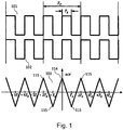
- the subcarrier 101, 102 itself has a saw-tooth like autocorrelation function 103 as shown in Fig. 1 for a BOC(10,5) signal.
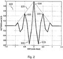
- the autocorrelation function 113 of a BOC signal is approximately given by the multiplication of a triangular PRN-code autocorrelation function 123 with the subcarrier autocorrelation function 103. Therefore, this autocorrelation function 113 has multiple peaks as shown in FIG. 2 for a BOCcos(10,5) signal.
- the autocorrelation function 113 which exhibits multiple peaks has advantages and disadvantages:
- the main peak 114 of the autocorrelation function 113 is significantly narrower than the single peak of the autocorrelation function 123 of the corresponding BPSK signal. This offers the potential for an increased tracking accuracy, i.e. less code jitter, and a better multipath performance. In particular, this may be used for determining (i.e. for tracking) a transmission delay of the BOC signals with increased accuracy. The transmission delay of the BOC signal may then be used for determining the position of a GNSS receiver.
- a tracking loop may lock to a side peak 115 instead of the main peak 114. If the locking to a side peak 115 is not recognized and corrected, systematic errors in the pseudo-range measurements occur, which in turn lead to position errors.
- a BOCcos(15,2.5) (also referred to as BOCc(15,2.5)) modulated signal i.e. a BOC modulated signal using a subcarrier which is phase shifted by 90 degrees with respect to the PRN code
- a false lock to the first side peak 115 leads to a pseudo-range error of approximately 10 meter, and for a BOCcos(10,5) modulated signal, this error is approximately 15 meter.
- a tracking loop locks to a side peak 115 further away from the main peak 114, such that the resulting error is a multiple of the error for a false lock to the first side peak 115.
- the US patent application US 2010/0104046 A1 describes the Double Estimator technique, which consists of three independent but cooperative loops for carrier, subcarrier, and code.
- the Double Estimator provides two independent delay estimates, one from code tracking, and one from subcarrier tracking.
- the code tracking delay estimate ⁇ is less accurate, while the subcarrier tracking delay estimate ⁇ * is ambiguous with the subcarrier chip duration T S .
- Double Phase Estimator Another approach is the Double Phase Estimator, described in the publication " Double Phase Estimator Towards a New Perception of the Subcarrier Component", D. Borio, InsideGNSS, May/June 2015, http://www.insidegnss.com, available under http://www.insidegnss.com/auto/mayjune15-WP.pdf .
- the difference between the Double Estimator and the Double Phase Estimator is that the Double Phase Estimator uses an arctan discriminator like it is used in PLLs (Phase Lock Loops) for subcarrier tracking.
- the tracking method disclosed in this application employs two independent but cooperative loops: One loop is used for carrier tracking, which is similar to a conventional PLL or FLL (Frequency Lock Loop). The other loop is performing a subcarrier tracking using an early-minus-late discriminator. Additionally, the subcarrier loop NCO (Numerical Controlled Oscillator) produces two replica signals composed of a prompt subcarrier, multiplied in one case with an early code replica, in the other case multiplied with a late code replica. These two replicas are correlated with the incoming signal, and the two correlation results are provided to an early-minus-late discriminator for detection of false locks to a side-peak of the subcarrier lock loop.
- NCO Numerical Controlled Oscillator
- This invention presents an alternative tracking algorithm for BOC and MBOC signals, fully exploiting the subcarrier accuracy and allowing for reliable, fast and robust detection and correction of false locks to side peaks.
- the invention exploits the nature of early-minus-late (EML) and arctan discriminators.
- EML discriminator is to be understood in a generalized sense, i.e. possible implementations are dot-product-power, early-minus-late-power, early-minus-late-envelope, but also double-delta, to name a few. All of them can be implemented as coherent or non-coherent discriminators. Typically, these discriminators are used in the DLL (Delay Lock Loop) of a GNSS receiver.
- DLL Delay Lock Loop
- arctan discriminator is to be understood in a generalized sense as well, possible implementations are Costas, IQ-product, decision-directed Q, Q-over-I, and two-quadrant arctangent discriminators, to name a few, but also FLL discriminators. Typically, these discriminators are used in a PLL, or in the latter case a FLL, of a GNSS receiver.
- An first embodiment of the invention which is based on the Double Estimator technique or Double Phase Estimator technique, relates to a system for tracking of a received signal s(t) with at least one subcarrier, wherein the received signal represents a carrier signal modulated with a code signal and modulated with a subcarrier signal, wherein the system comprises the following independent and cooperatively operating loops:
- a second embodiment of the invention which is based on the approach described in the European patent application EP13290093.7 , relates to a system for tracking of a received signal s(t) with at least one subcarrier, wherein the received signal represents a carrier signal modulated with a code signal and modulated with a subcarrier signal, wherein the system comprises the following independent and cooperatively operating loops:
- the early-minus-late discriminator may be implemented as a dot-product-power discriminator, an early-minus-late-power discriminator, an early-minus-late-envelope discriminator, or a double-delta discriminator.
- the early-minus-late discriminator may be implemented as a coherent or a non-coherent discriminator.
- At least one of the arctan discriminators may be implemented as a Costas discriminator, an IQ-product discriminator, a decision-directed Q discriminator, a Q-over-I discriminator or a two-quadrant arctangent discriminator.
- the controllable oscillators may be implemented by numerical controlled oscillators.
- the system may be configured for tracking a Binary Offset Carrier signal, a Multiplexed Binary Offset Carrier signal, a Composite Binary Offset Carrier signal, and/or a Composite Binary Offset Carrier signal using a cosine subcarrier.
- a further embodiment of the invention which corresponds to the first embodiment of the system, relates to a method for tracking a received signal s(t) with at least one subcarrier, wherein the received signal represents a carrier signal modulated with a code signal and modulated with a subcarrier signal, wherein the method comprises the following independently and cooperatively performed acts of:
- a yet further embodiment of the invention which corresponds to the second embodiment of the system, relates to a method for tracking a received signal s(t) with at least one subcarrier, wherein the received signal represents a carrier signal modulated with a code signal and modulated with a subcarrier signal, wherein the method comprises the following independently and cooperatively performed acts of:
- a further embodiment of the invention relates to a computer program, which implements at least one method according to the invention and as described herein and enables the tracking of a received signal s(t) with at least one subcarrier according to the invention when executed by a computer, which is equipped with means for receiving a signal with at least one subcarrier signals such as an antenna and a RF (Radio Frequency) front end.
- a computer which is equipped with means for receiving a signal with at least one subcarrier signals such as an antenna and a RF (Radio Frequency) front end.
- a record carrier storing a computer program according to the invention may be provided, for example a CD-ROM, a DVD, a memory card, a diskette, or a similar data carrier suitable to store the computer program for electronic access.
- the present application relates to tracking a subcarrier modulated signal.
- the invention exploits the nature of early-minus-late (EML) and arctan discriminators.
- An EML discriminator calculates the tracking error from two inputs. For a BPSK signal for example, these inputs would be obtained by correlating the incoming signal after carrier wipe-off with early and late PRN code replicas, respectively. This can be seen as sampling the correlation function at two points, the distance between these points is called early-late spacing.
- An EML discriminator provides outputs that can be used to steer the NCO of a tracking loop, as long as the inputs provided stem from sampling a function, which has a maximum at zero tracking error, and decreases with an increasing absolute value of the tracking error, at least as long as the tracking error is small enough.
- Fig. 3 shows a hypothetical correlation function, which is sampled at two point with a certain early-late spacing.
- the early and late inputs to the discriminator function have the same value. This is the case if the timing of the incoming signal is known perfectly, because then the early and late replicas for correlation are delayed and advanced, respectively, by exactly the same amount w.r.t the incoming signal.
- the EML discriminator output will be zero. In case the timing of the incoming signal is not known perfectly, the shift of the early and late replicas is not symmetric to the incoming signal.
- the sampling of the correlation function will result in two different values, and the EML discriminator will output a quantity that is ideally proportional to the tracking error. This situation is depicted in Fig. 3 with the square sampling points.
- An arctan discriminator provides an output that can be used to steer a tracking loop, if the input value provided as numerator for the arctan function is zero for a zero tracking error, and increases (respectively decreases) with increasing (respectively decreasing) tracking error.
- the input value provided as denominator needs to have its maximum value at zero tracking error, and decreases with an increasing absolute value of the tracking error.
- the known Double Estimator approach or architecture consists of three independent but cooperative loops for carrier, subcarrier, and code. These loops are called phase lock loop (PLL), subcarrier lock loop (SLL), and delay lock loop (DLL).
- PLL phase lock loop
- SLL subcarrier lock loop
- DLL delay lock loop
- the Double Estimator uses EML discriminators in the SLL and the DLL, the PLL employs a arctan discriminator.
- the Double Phase Estimator uses an EML discriminator for DLL, and arctan discriminators for PLL and SLL. It should be noted that the arctan discriminator needs two real inputs. Due to PLL tracking errors, the correlation results are in general complex.
- the invention proposes two new tracking structures, which differ from the known Double Estimator and the known Double Phase Estimator in that sense that they use
- the replica for generation of the numerator input contains the difference of a delayed and an advanced PRN code
- the replica for generation of the denominator contains a prompt PRN code
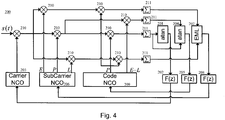
- FIG.4 A block diagram of the tracking architecture according to OPTION1 is shown in Fig.4
- the block diagram for OPTION2 is shown in Fig.5 .
- the complex inputs to the arctan discriminators are handled in the same way as described in the section above on the Double Phase Estimator.
- Fig. 4 and 5 show block diagrams of tracking systems according to OPTION1 (system 200 shown in Fig. 4 ) and to OPTION2 (system 300 shown in Fig. 5 ).
- Fig. 4 and 5 do not show means for navigation message demodulation and decoding, as well as a RF (radio frequency) front-end and an ADC (analogue-to-digital converter).
- the signals of Fig. 4 and 5 are to be understood as complex baseband signals, meaning that the received signal s(t), which represents a carrier signal modulated with a code signal and modulated with a subcarrier signal, is assumed to be downconverted into the baseband. It should be noted, however, that the systems 200 and 300 may operate at intermediate frequencies (IF) or directly at RF in a similar manner.
- IF intermediate frequencies
- Both tracking systems 200 and 300 employ three independent, but cooperative feedback loops.
- a first loop is used for carrier tracking, i.e. for the locking to the phase and frequency of the carrier signal.
- the first loop may make use of PLL (phase lock loop) and/or FLL (frequency lock loop) techniques.
- the first loop of system 200 (300) comprises an arctan discrimination unit 201 (301), a first filter unit 202 (302) and a first oscillator unit 203 (303) (comprising e.g. a numerically controlled oscillator, NCO).
- a second loop is used for subcarrier tracking, i.e. for tracking the subcarrier signal.
- the second loop of system 200 comprises an early-minus-late discrimination unit 207, a second filter unit 208 and a second oscillator unit 206 (comprising e.g. a NCO).
- the second loop of system 300 comprises an arctan discrimination unit 307, a second filter unit 308 and a second oscillator unit 306 (comprising e.g. a NCO).
- a third loop is used for code tracking, i.e. for tracking the code signal.
- the third loop of system 200 comprises an arctan discrimination unit 204 (304), a third filter unit 205 (305) and a third oscillator unit 209 (309) (comprising e.g. a NCO).
- a subcarrier modulated signal may further comprise navigation message data.
- navigation message bits are ignored, as the presence of navigation bits is not relevant for the principle considerations regarding signal tracking.
- the effects of noise, dynamics and multipath on the tracking loop are also not included in the following discussion.
- the tracking of a BOC, CBOC and/or MBOC modulated signal may be performed using the three independent but cooperative loops, wherein the first loop is used for tracking the carrier (e.g. based on a PLL or a FLL). The second loop is used for tracking the subcarrier signal (using a SLL). And the third loop is used for tracking the code signal (using a DLL)
- the tracking systems 200 and 300 shown in Fig. 4 and 5 are designed for tracking subcarrier modulated signals, such as BOC, CBOC and/or MBOC modulated signals.
- the system 200 (300) is configured to track the subcarrier signal sc(t) and the code signal a(t).
- the second loop of system 200 (300) is closed by tracking the subcarrier sc(t) (also referred to as subcarrier signal).
- the third loop of system 200 (300) is closed by tracking the code a(t) (also referred to as code signal).
- the second oscillator unit 206 is configured to generate three replicas of the subcarrier modulated signal, namely an E(arly), P(rompt), and L(ate) replica of the subcarrier modulated signal.
- the third oscillator unit 209 is configured to generate a P(rompt) PRN code and the difference of an early and a late (E-L) PRN code.
- the second oscillator unit 306 is configured to generate a cosine subcarrier modulated signal cos and a sine subcarrier modulated signal sin.
- the third oscillator unit 309 is configured to generate a P(rompt) PRN code and the difference of an early and a late (E-L) PRN code.
- a multiplying unit 210 performs a carrier wipe-off by multiplying the received signal s(t) with output signal of the first oscillator unit 203 (303).
- further multiplying units 210 multiply the received signal s(t) after carrier wipe-off with the E, P, and L replica of the subcarrier modulated signal.
- the signal resulting from the multiplication with the P subcarrier replica is further multiplied with a (P)rompt code replica by a further multiplying unit 210, which yields a signal that is, after integrated by an integration unit 211, used for carrier loop closure in the arctan discrimination unit 201, and contributes to code loop closure in the arctan discrimination unit 204.
- the signal resulting from the multiplication with the P subcarrier replica is also further multiplied with an early-minus-late (E-L) code replica by a further multiplying unit 210, which yields a signal that is, after integrated by an integration unit 211, also contributing to code loop closure in the arctan discrimination unit 204.
- the signals resulting from the multiplication with the E and L subcarrier replicas are further multiplied with a (P)rompt code replica by a further multiplying unit 210, which yields signals that as, after integrated by an integration units 211, used for subcarrier loop closure in the the EML discrimination unit 207.
- further multiplying units 310 multiply the received signal s(t) after carrier wipe-off with cosine and sine subcarrier replicas.
- the two resulting signals are multiplied by a prompt code replica in multiplying units 310, the resulting signals are integrated by an integration unit 311, and are used for carrier loop closure using the arctan discriminator unit 301, for subcarrier loop closure in the arctan discriminator unit 307, and contribute to the code loop closure in the early-minus-late discriminator unit 304.
- the signal resulting from the multiplication with the cosine replica is further multiplied in the multiplying uint 310 with an (E-L) PRN code, which also contributes, after integration in the integration unit 311, to code loop closure.
- the invention proposes two additional new tracking structures, which differ from the correlator known from the European patent application EP13290093.7 in that sense that they use
- PP denotes a replica composed of a prompt subcarrier and a prompt PRN code
- EP denotes a replica composed of an early subcarrier and a prompt PRN code
- LP denotes a replica composed of a late subcarrier and a prompt PRN code
- code P(E-L) denotes a replica composed of a prompt subcarrier and the difference of an early and a late PRN code.
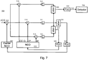
- OPTION4 is shown in Fig. 7 .
- CP denotes a replica composed of a cosine subcarrier and a prompt PRN code
- SP denotes a replica composed of a sine subcarrier and a prompt PRN code
- C(E-L) denotes a replica composed of a cosine subcarrier and the difference of an early and a late PRN code.
- Fig. 6 and 7 show block diagrams of tracking systems according to OPTION3 (system 400 shown in Fig. 6 ) and to OPTION4 (system 500 shown in Fig. 7 ).
- Fig. 6 and 7 do not show means for navigation message demodulation and decoding, as well as a RF (radio frequency) front-end and an ADC (analogue-to-digital converter).
- the signals of Fig. 6 and 7 are to be understood as complex baseband signals, meaning that the received signal s(t), which represents a carrier signal modulated with a code signal and modulated with a subcarrier signal, is assumed to be downconverted into the baseband.
- the systems 400 and 500 may operate at intermediate frequencies (IF) or directly at RF in a similar manner.
- IF intermediate frequencies
- Both tracking systems 400 and 500 employ two independent but cooperative feedback loops.
- a first loop is used for carrier tracking, i.e. for the locking to the phase and frequency of the carrier signal.
- the first loop may make use of PLL (phase lock loop) and/or FLL (frequency lock loop) techniques.
- the first loop of system 400 (500) comprises an arctan discrimination unit 401 (501), a first filter unit 402 (502) and a first oscillator unit 403 (503) (comprising e.g. a numerically controlled oscillator, NCO).
- a second loop is used for subcarrier racking, i.e. for tracking the subcarrier signal.
- the second loop of system 400 comprises an EML discrimination unit 407, a second filter unit 408 and a second oscillator unit 409 (comprising e.g. a NCO).
- the second loop of system 500 comprises an arctan discrimination unit 507, a second filter unit 508 and a second oscillator unit 509 (comprising e.g. a NCO).
- the second loop may be used to produce a disambiguation signal 412 (512) that can be filtered and compared to a threshold in order to detect a false lock to a side peak 115 of the autocorrelation function 103.
- a subcarrier modulated signal may further comprise navigation message data.
- navigation message bits are ignored, as the presence of navigation bits is not relevant for the principle considerations regarding signal tracking.
- the effects of noise, dynamics and multipath on the tracking loop are also not included in the following discussion.
- the tracking of a BOC, CBOC and/or MBOC modulated signal may be performed using the two independent but cooperative loops, wherein the first loop is used for tracking the carrier (e.g. based on a PLL or a FLL). The second loop is used for tracking the subcarrier signal and the code signal.
- the first loop is used for tracking the carrier (e.g. based on a PLL or a FLL).
- the second loop is used for tracking the subcarrier signal and the code signal.
- the tracking systems 400 and 500 shown in Fig. 6 and 7 are designed for tracking subcarrier modulated signals, such as BOC, CBOC and/or MBOC modulated signals.
- the system 400 (500) is configured to track the transmission delay ⁇ , i.e. to determine an estimate ⁇ ' of the transmission delay ⁇ .
- the second loop of system 400 (500) is closed by tracking the subcarrier sc(t) (also referred to as subcarrier signal). This may be achieved using the second oscillator unit 409 (509) which is configured to generate e.g. several replicas of the subcarrier modulated signal.
- the second oscillator unit 409 is configured to generate the PP replica composed of a prompt subcarrier and a prompt PRN code, the EP replica composed of an early subcarrier and a prompt PRN code, the LP replica composed of a late subcarrier and a prompt PRN code, and the code P(E-L) replica composed of a prompt subcarrier and the difference of an early and a late PRN code.
- the second oscillator unit 509 is configured to generate the CP replica composed of a cosine subcarrier and a prompt PRN code, the SP replica composed of a sine subcarrier and a prompt PRN code, the C(E-L) replica composed of a cosine subcarrier and the difference of an early and a late PRN code.
- a multiplying unit 410 performs a carrier wipe-off by multiplying the received signal s(t) with output signal of the first oscillator unit 403 (503).
- further multiplying units 410 multiply the received signal s(t) after carrier wipe-off with the code P(E-L) replica, the PP replica, the EP replica, and the LP replica.
- the multiplication with the EP and LP replicas performs a code wipe-off and, then, the code wiped off signals are integrated by integration units 411 and input to the EML discrimination unit 407 to estimate a subcarrier tracking error, which is fed to the filter unit 408 in order to generate a steering command for the second oscillator unit 409.
- the multiplication with the PP replica performs a subcarrier wipe-off resulting in the subcarrier wiped off signal as output, which is integrated by an integration unit 411 and then input to the arctan discrimination unit 401 for estimating the carrier tracking error, which is fed to the filter unit 408 in order to generate a steering command for the first oscillator unit 403.
- the subcarrier wiped-off signal multiplied with the code P(E-L) replica is input to the arctan discrimination unit 404, which also receives the integrated carrier signal.
- the arctan discrimination unit 404 is part of a detection path comprising a filter unit 405 and a detector 406 for determining a delay offset, which is the difference between the locked delay offset and the actual delay offset.
- further multiplying units 510 multiply the received signal s(t) after carrier wipe-off with the CP replica composed of a cosine subcarrier and a prompt PRN code, the SP replica composed of a sine subcarrier and a prompt PRN code, and the C(E-L) replica composed of a cosine subcarrier and the difference of an early and a late PRN code.
- the multiplication with the SP replica and the CP replica performs a code wipe-off and, then, the code wiped off signals are integrated by integration unit 511 and input to the arctan discrimination unit 507 to estimate a subcarrier tracking error, which is fed to the filter unit 508 in order to generate a steering command for the second oscillator unit 509.
- the multiplication with the CP replica performs a code and subcarrier wipe-off resulting in the code and subcarrier wiped off signal as output, which is integrated by an integration unit 511 and then input to the arctan discrimination unit 501 for estimating the carrier tracking error, which is fed to the filter unit 502 in order to generate a steering command for the first oscillator unit 503.
- the subcarrier wiped-off signal multiplied with the C(E-L) replica is after integration by an integration unit 511 input to the arctan discrimination unit 504, which also receives the integrated carrier signal.
- the arctan discrimination unit 504 is part of a detection path comprising a filter unit 505 and a detector 506 for determining a delay offset, which is the difference between the locked delay offset and the actual delay offset.
- At least some of the functionality of the invention may be performed by hard- or software.
- a single or multiple standard microprocessors or microcontrollers may be used to process a single or multiple algorithms implementing the invention.
- a FPGA Field Programmable Gate Array
- ASIC Application Specific Integrated Circuit
Landscapes
- Engineering & Computer Science (AREA)
- Radar, Positioning & Navigation (AREA)
- Remote Sensing (AREA)
- Computer Networks & Wireless Communication (AREA)
- Physics & Mathematics (AREA)
- General Physics & Mathematics (AREA)
- Signal Processing (AREA)
- Spectroscopy & Molecular Physics (AREA)
- Synchronisation In Digital Transmission Systems (AREA)
Description
- The invention relates to the tracking of signals with at least one subcarrier such as Binary Offset Carrier (BOC) modulated signals. Particularly, the present invention relates to tracking of BOC (modulated) signals of a GNSS (Global Navigation Satellite System).
- In next generation GNSSs, BOC modulations and multiplexed BOC (MBOC) modulations will be used. Examples are the Galileo E1 open signal, a CBOC(6,1,1/11) signal (Composite BOC using a sine subcarrier), the Galileo PRS (Public Regulated Service) signals on E1 and E6, a BOCc(15,2.5) signal and a BOCc(10,5) signal, respectively, and the GPS (Global Positioning System) M-code, a BOC(10,5) signal. In more general terms, the above mentioned signals may be referred to as subcarrier modulated signals. Such subcarrier modulated signals comprise a carrier signal, which is modulated with a pseudo random noise (PRN) code, and which is additionally modulated with one or more subcarriers. Additionally, navigation message data may or may not be modulated onto the carrier signal.
- A BOC modulated signal without the subcarrier modulation corresponds to a Binary Phase Shift Keying (BPSK) signal used like it is used for GPS SPS (Standard Positioning Service), which has a triangular autocorrelation function.
Fig. 1 shows anexample subcarrier signal 
Fig. 1 also illustrates the symbol duration
subcarrier autocorrelation function 103 as shown inFig. 1 for a BOC(10,5) signal. Theautocorrelation function 113 of a BOC signal is approximately given by the multiplication of a triangular PRN-code autocorrelation function 123 with thesubcarrier autocorrelation function 103. Therefore, thisautocorrelation function 113 has multiple peaks as shown inFIG. 2 for a BOCcos(10,5) signal. - The
autocorrelation function 113 which exhibits multiple peaks has advantages and disadvantages: Themain peak 114 of theautocorrelation function 113 is significantly narrower than the single peak of theautocorrelation function 123 of the corresponding BPSK signal. This offers the potential for an increased tracking accuracy, i.e. less code jitter, and a better multipath performance. In particular, this may be used for determining (i.e. for tracking) a transmission delay of the BOC signals with increased accuracy. The transmission delay of the BOC signal may then be used for determining the position of a GNSS receiver. - On the other hand, a tracking loop may lock to a
side peak 115 instead of themain peak 114. If the locking to aside peak 115 is not recognized and corrected, systematic errors in the pseudo-range measurements occur, which in turn lead to position errors. For a BOCcos(15,2.5) (also referred to as BOCc(15,2.5)) modulated signal, i.e. a BOC modulated signal using a subcarrier which is phase shifted by 90 degrees with respect to the PRN code, a false lock to thefirst side peak 115 leads to a pseudo-range error of approximately 10 meter, and for a BOCcos(10,5) modulated signal, this error is approximately 15 meter. However, it is also possible that a tracking loop locks to aside peak 115 further away from themain peak 114, such that the resulting error is a multiple of the error for a false lock to thefirst side peak 115. - Different techniques have been proposed for tracking these signals, e.g. bump jumping, a Sidelobe Cancellation Method, BPSK-like techniques, a Multiple Gate Delay discriminator, and a Double Estimator technique to name a few.
- The US patent application
US 2010/0104046 A1 describes the Double Estimator technique, which consists of three independent but cooperative loops for carrier, subcarrier, and code. The Double Estimator provides two independent delay estimates, one from code tracking, and one from subcarrier tracking. The code tracking delay estimate τ is less accurate, while the subcarrier tracking delay estimate τ* is ambiguous with the subcarrier chip duration TS. The final delay estimate τfinal is then calculated by resolving the subcarrier delay ambiguity using the less accurate code delay estimate, for example by rounding the difference of code delay and subcarrier delay, both divided by the subcarrier chip duration, to the nearest integer and adding the result multiplied by the subcarrier chip duration to the subcarrier delay:
- Another approach is the Double Phase Estimator, described in the publication "Double Phase Estimator Towards a New Perception of the Subcarrier Component", D. Borio, InsideGNSS, May/June 2015, http://www.insidegnss.com, available under http://www.insidegnss.com/auto/mayjune15-WP.pdf. The difference between the Double Estimator and the Double Phase Estimator is that the Double Phase Estimator uses an arctan discriminator like it is used in PLLs (Phase Lock Loops) for subcarrier tracking.
- A further approach is described in the European patent application
EP13290093.7 - It is an object of the present invention to propose an alternative tracking of signals with at least one subcarrier such as BOC and MBOC signals.
- This object is achieved by the subject matter of the independent claims. Further embodiments are shown by the dependent claims.
- This invention presents an alternative tracking algorithm for BOC and MBOC signals, fully exploiting the subcarrier accuracy and allowing for reliable, fast and robust detection and correction of false locks to side peaks. The invention exploits the nature of early-minus-late (EML) and arctan discriminators. Hereby, the expression EML discriminator is to be understood in a generalized sense, i.e. possible implementations are dot-product-power, early-minus-late-power, early-minus-late-envelope, but also double-delta, to name a few. All of them can be implemented as coherent or non-coherent discriminators. Typically, these discriminators are used in the DLL (Delay Lock Loop) of a GNSS receiver. Additionally, the expression arctan discriminator is to be understood in a generalized sense as well, possible implementations are Costas, IQ-product, decision-directed Q, Q-over-I, and two-quadrant arctangent discriminators, to name a few, but also FLL discriminators. Typically, these discriminators are used in a PLL, or in the latter case a FLL, of a GNSS receiver.
- An first embodiment of the invention, which is based on the Double Estimator technique or Double Phase Estimator technique, relates to a system for tracking of a received signal s(t) with at least one subcarrier, wherein the received signal represents a carrier signal modulated with a code signal and modulated with a subcarrier signal, wherein the system comprises the following independent and cooperatively operating loops:
- A phase lock loop for tracking the carrier signal.
- A subcarrier lock loop for tracking the subcarrier signal, which comprises a controllable oscillator and an early-minus-late discriminator for generating a control signal for the controllable oscillator, wherein the early-minus-late discriminator generates the control signal based on a difference between correlation results with a replica of an advanced subcarrier signal E and a replica of a delayed subcarrier signal L. Alternatively, the subcarrier lock loop comprises a controllable oscillator and an arctan discriminator for generating a control signal for the controllable oscillator, wherein the arctan discriminator generates the control signal based on correlation results with a cosine subcarrier replica and a sine subcarrier replica.
- A delay lock loop for tracking the code signal, which comprises a controllable oscillator and an arctan discriminator for generating a control signal for the controllable oscillator, wherein the arctan discriminator generates the control signal based on correlation results with a replica of a prompt subcarrier signal P multiplied with a prompt code signal and the replica of the prompt subcarrier signal P multiplied with the difference of an advanced and a delayed code signal, E-L.
- A second embodiment of the invention, which is based on the approach described in the European patent application
EP13290093.7 - A phase lock loop for tracking the carrier signal.
- A subcarrier lock loop for tracking the subcarrier signal, which comprises a controllable oscillator and an early-minus-late discriminator for generating a control signal for the controllable oscillator, wherein the early-minus-late discriminator generates the control signal based on a difference between correlation results with a replica composed of an early subcarrier signal and a prompt code signal EP and a replica composed of a late subcarrier signal and a prompt code signal LP. Alternatively, the subcarrier lock loop comprises a controllable oscillator and an arctan discriminator for generating a control signal for the controllable oscillator, wherein the arctan discriminator generates the control signal based on the correlation results with a replica composed of a sine subcarrier signal and a prompt code signal SP and a replica composed of a cosine subcarrier signal and a prompt code signal CP.
- A detection path for detecting a delay estimate of the code signal, which comprises an arctan discriminator and a delay estimate detector, wherein the arctan discriminator generates an input signal for the delay estimate detector based on the correlation results with a replica composed of a prompt subcarrier signal and the difference of an early and a late code signal P(E-L) and a replica composed of a prompt subcarrier signal and a prompt code signal PP.
- The early-minus-late discriminator may be implemented as a dot-product-power discriminator, an early-minus-late-power discriminator, an early-minus-late-envelope discriminator, or a double-delta discriminator.
- The early-minus-late discriminator may be implemented as a coherent or a non-coherent discriminator.
- At least one of the arctan discriminators may be implemented as a Costas discriminator, an IQ-product discriminator, a decision-directed Q discriminator, a Q-over-I discriminator or a two-quadrant arctangent discriminator.
- The controllable oscillators may be implemented by numerical controlled oscillators.
- The system may be configured for tracking a Binary Offset Carrier signal, a Multiplexed Binary Offset Carrier signal, a Composite Binary Offset Carrier signal, and/or a Composite Binary Offset Carrier signal using a cosine subcarrier.
- A further embodiment of the invention, which corresponds to the first embodiment of the system, relates to a method for tracking a received signal s(t) with at least one subcarrier, wherein the received signal represents a carrier signal modulated with a code signal and modulated with a subcarrier signal, wherein the method comprises the following independently and cooperatively performed acts of:
- Tracking the carrier signal with a phase lock loop.
- Tracking the subcarrier signal with a subcarrier lock loop, which comprises a controllable oscillator and an early-minus-late discriminator for generating a control signal for the controllable oscillator, wherein the early-minus-late discriminator generates the control signal based on a difference between correlation results with a replica of an advanced subcarrier signal E and a replica of a delayed subcarrier signal L. Alternatively, the subcarrier lock loop comprises a controllable oscillator and an arctan discriminator for generating a control signal for the controllable oscillator, wherein the arctan discriminator generates the control signal based on correlation results with a cosine subcarrier replica and a sine subcarrier replica. It is understood that a code wipe-off has to be performed in both cases.
- Tracking the code signal with a delay lock loop, which comprises a controllable oscillator and an arctan discriminator for generating a control signal for the controllable oscillator, wherein the arctan discriminator generates the control signal based on correlation results with a replica of a prompt subcarrier signal P multiplied with a prompt code signal and the replica of the prompt subcarrier signal P multiplied with the difference of an advanced and a delayed code signal E-L. Instead of prompt subcarrier, also the wording cosine subcarrier could be used.
- A yet further embodiment of the invention, which corresponds to the second embodiment of the system, relates to a method for tracking a received signal s(t) with at least one subcarrier, wherein the received signal represents a carrier signal modulated with a code signal and modulated with a subcarrier signal, wherein the method comprises the following independently and cooperatively performed acts of:
- Tracking the carrier signal with a phase lock loop.
- Tracking the subcarrier signal with a subcarrier lock loop, which comprises a controllable oscillator and an early-minus-late discriminator for generating a control signal for the controllable oscillator, wherein the early-minus-late discriminator generates the control signal based on a difference between correlation results with a replica composed of an early subcarrier signal and a prompt code signal EP and a replica composed of a late subcarrier signal and a prompt code signal LP. Alternatively, the subcarrier lock loop comprises a controllable oscillator and an arctan discriminator for generating a control signal for the controllable oscillator, wherein the arctan discriminator generates the control signal based on correlation results with a replica composed of a sine subcarrier signal and a prompt code signal SP and a replica composed of a cosine subcarrier signal and a prompt code signal CP.
- Detecting a delay estimate of the code signal with a detection path, which comprises an arctan discriminator and a delay estimate detector, wherein the arctan discriminator generates an input signal for the delay estimate detector based on the correlation results with a replica composed of a prompt subcarrier signal and the difference of an early and a late code signal P(E-L) and a replica composed of a prompt subcarrier signal and a prompt code signal PP.
- A further embodiment of the invention relates to a computer program, which implements at least one method according to the invention and as described herein and enables the tracking of a received signal s(t) with at least one subcarrier according to the invention when executed by a computer, which is equipped with means for receiving a signal with at least one subcarrier signals such as an antenna and a RF (Radio Frequency) front end.
- According to a further embodiment of the invention, a record carrier storing a computer program according to the invention may be provided, for example a CD-ROM, a DVD, a memory card, a diskette, or a similar data carrier suitable to store the computer program for electronic access.
- These and other aspects of the invention will be apparent from and elucidated with reference to the embodiments described hereinafter.
- The invention will be described in more detail hereinafter with reference to exemplary embodiments. However, the invention is not limited to these exemplary embodiments.
-
-
Fig. 1 shows an example subcarrier signal used for modulating a carrier signal and its saw-tooth like autocorrelation function; -
Fig. 2 shows an autocorrelation function of an example subcarrier modulated signal; -
Fig. 3 shows a hypothetical correlation function of an example subcarrier modulated signal, which is sampled at two points with a certain early-late spacing; -
Fig. 4 shows a block diagram of a system for tracking a subcarrier modulated signal according to the invention, which differs from the known Double Estimator and Double Phase Estimator approaches by using an EML discriminator for SLL (Subcarrier Lock Loop) and an arctan discriminator for DLL; -
Fig. 5 shows a block diagram of a system for tracking a subcarrier modulated signal according to the invention, which differs from the known Double Estimator and Double Phase Estimator approaches by using an arctan discriminator for SLL and DLL according to the invention; -
Fig. 6 shows a block diagram of a system for tracking a subcarrier modulated signal according to the invention, which differs from the correlator known from the European patent applicationEP13290093.7 -
Fig. 7 shows a block diagram of a system for tracking a subcarrier modulated signal according to the invention, which differs from the correlator known from the European patent applicationEP13290093.7 - In the following, functionally similar or identical elements may have the same reference numerals. Absolute values are shown below by way of example only and should not be construed as limiting the invention.
- As outlined in the background section, the present application relates to tracking a subcarrier modulated signal.
- As explained above, the invention exploits the nature of early-minus-late (EML) and arctan discriminators.
- An EML discriminator calculates the tracking error from two inputs. For a BPSK signal for example, these inputs would be obtained by correlating the incoming signal after carrier wipe-off with early and late PRN code replicas, respectively. This can be seen as sampling the correlation function at two points, the distance between these points is called early-late spacing.
- An EML discriminator provides outputs that can be used to steer the NCO of a tracking loop, as long as the inputs provided stem from sampling a function, which has a maximum at zero tracking error, and decreases with an increasing absolute value of the tracking error, at least as long as the tracking error is small enough.
- This principle is illustrated in
Fig. 3 . It shows a hypothetical correlation function, which is sampled at two point with a certain early-late spacing. In the case denoted with the circular sampling points, the early and late inputs to the discriminator function have the same value. This is the case if the timing of the incoming signal is known perfectly, because then the early and late replicas for correlation are delayed and advanced, respectively, by exactly the same amount w.r.t the incoming signal. The EML discriminator output will be zero. In case the timing of the incoming signal is not known perfectly, the shift of the early and late replicas is not symmetric to the incoming signal. The sampling of the correlation function will result in two different values, and the EML discriminator will output a quantity that is ideally proportional to the tracking error. This situation is depicted inFig. 3 with the square sampling points. - An arctan discriminator provides an output that can be used to steer a tracking loop, if the input value provided as numerator for the arctan function is zero for a zero tracking error, and increases (respectively decreases) with increasing (respectively decreasing) tracking error. The input value provided as denominator needs to have its maximum value at zero tracking error, and decreases with an increasing absolute value of the tracking error.
- As mentioned previously, the known Double Estimator approach or architecture consists of three independent but cooperative loops for carrier, subcarrier, and code. These loops are called phase lock loop (PLL), subcarrier lock loop (SLL), and delay lock loop (DLL). The Double Estimator uses EML discriminators in the SLL and the DLL, the PLL employs a arctan discriminator. In opposite to that, the Double Phase Estimator uses an EML discriminator for DLL, and arctan discriminators for PLL and SLL. It should be noted that the arctan discriminator needs two real inputs. Due to PLL tracking errors, the correlation results are in general complex. Therefore, in the arctan discriminator either the real parts of the two inputs are calculated and used as numerator and denominator, or the real part of the fraction of the two complex inputs is used, see http://www.insidegnss.com/auto/mayjune15-WP.pdf.
- The invention proposes two new tracking structures, which differ from the known Double Estimator and the known Double Phase Estimator in that sense that they use
- OPTION1: EML discriminator for SLL, arctan discriminator for DLL
- OPTION2: Arctan discriminator for SLL and DLL
- In order to use an arctan discriminator in the DLL, i.e. for code tracking, the replica for generation of the numerator input contains the difference of a delayed and an advanced PRN code, the replica for generation of the denominator contains a prompt PRN code.
- A block diagram of the tracking architecture according to OPTION1 is shown in
Fig.4 , the block diagram for OPTION2 is shown inFig.5 . The complex inputs to the arctan discriminators are handled in the same way as described in the section above on the Double Phase Estimator. - Next, the inventive tracking architectures shown in
Fig. 4 and5 are described in detail. -
Fig. 4 and5 show block diagrams of tracking systems according to OPTION1 (system 200 shown inFig. 4 ) and to OPTION2 (system 300 shown inFig. 5 ). For sake of simplicity,Fig. 4 and5 do not show means for navigation message demodulation and decoding, as well as a RF (radio frequency) front-end and an ADC (analogue-to-digital converter). The signals ofFig. 4 and5 are to be understood as complex baseband signals, meaning that the received signal s(t), which represents a carrier signal modulated with a code signal and modulated with a subcarrier signal, is assumed to be downconverted into the baseband. It should be noted, however, that thesystems - Both tracking
systems - A first loop is used for carrier tracking, i.e. for the locking to the phase and frequency of the carrier signal. The first loop may make use of PLL (phase lock loop) and/or FLL (frequency lock loop) techniques. The first loop of system 200 (300) comprises an arctan discrimination unit 201 (301), a first filter unit 202 (302) and a first oscillator unit 203 (303) (comprising e.g. a numerically controlled oscillator, NCO).
- A second loop is used for subcarrier tracking, i.e. for tracking the subcarrier signal. The second loop of
system 200 comprises an early-minus-late discrimination unit 207, asecond filter unit 208 and a second oscillator unit 206 (comprising e.g. a NCO). The second loop ofsystem 300 comprises anarctan discrimination unit 307, asecond filter unit 308 and a second oscillator unit 306 (comprising e.g. a NCO). - A third loop is used for code tracking, i.e. for tracking the code signal. The third loop of system 200 (300) comprises an arctan discrimination unit 204 (304), a third filter unit 205 (305) and a third oscillator unit 209 (309) (comprising e.g. a NCO). It should be noted that a subcarrier modulated signal may further comprise navigation message data. In the following description, such navigation message bits are ignored, as the presence of navigation bits is not relevant for the principle considerations regarding signal tracking. Furthermore, for the sake of simplicity, the effects of noise, dynamics and multipath on the tracking loop are also not included in the following discussion.
- The tracking of a BOC, CBOC and/or MBOC modulated signal may be performed using the three independent but cooperative loops, wherein the first loop is used for tracking the carrier (e.g. based on a PLL or a FLL). The second loop is used for tracking the subcarrier signal (using a SLL). And the third loop is used for tracking the code signal (using a DLL)
- The
tracking systems Fig. 4 and5 , respectively, are designed for tracking subcarrier modulated signals, such as BOC, CBOC and/or MBOC modulated signals. The received signal s(t) may be denoted as
subcarrier signal 101 delayed by the transmission delay τ and a(t - τ) is the code (also referred to as code signal) delayed by the transmission delay τ. - The system 200 (300) is configured to track the subcarrier signal sc(t) and the code signal a(t). The second loop of system 200 (300) is closed by tracking the subcarrier sc(t) (also referred to as subcarrier signal). The third loop of system 200 (300) is closed by tracking the code a(t) (also referred to as code signal).
- In the
system 200, the second oscillator unit 206 is configured to generate three replicas of the subcarrier modulated signal, namely an E(arly), P(rompt), and L(ate) replica of the subcarrier modulated signal. Thethird oscillator unit 209 is configured to generate a P(rompt) PRN code and the difference of an early and a late (E-L) PRN code. - In the
system 300, the second oscillator unit 306 is configured to generate a cosine subcarrier modulated signal cos and a sine subcarrier modulated signal sin. Thethird oscillator unit 309 is configured to generate a P(rompt) PRN code and the difference of an early and a late (E-L) PRN code. - A multiplying unit 210 (310) performs a carrier wipe-off by multiplying the received signal s(t) with output signal of the first oscillator unit 203 (303).
- In
system 200, further multiplyingunits 210 multiply the received signal s(t) after carrier wipe-off with the E, P, and L replica of the subcarrier modulated signal. The signal resulting from the multiplication with the P subcarrier replica is further multiplied with a (P)rompt code replica by a further multiplyingunit 210, which yields a signal that is, after integrated by anintegration unit 211, used for carrier loop closure in thearctan discrimination unit 201, and contributes to code loop closure in thearctan discrimination unit 204. The signal resulting from the multiplication with the P subcarrier replica is also further multiplied with an early-minus-late (E-L) code replica by a further multiplyingunit 210, which yields a signal that is, after integrated by anintegration unit 211, also contributing to code loop closure in thearctan discrimination unit 204. The signals resulting from the multiplication with the E and L subcarrier replicas are further multiplied with a (P)rompt code replica by a further multiplyingunit 210, which yields signals that as, after integrated by anintegration units 211, used for subcarrier loop closure in the theEML discrimination unit 207. - In
system 300, further multiplyingunits 310 multiply the received signal s(t) after carrier wipe-off with cosine and sine subcarrier replicas. The two resulting signals are multiplied by a prompt code replica in multiplyingunits 310, the resulting signals are integrated by anintegration unit 311, and are used for carrier loop closure using thearctan discriminator unit 301, for subcarrier loop closure in thearctan discriminator unit 307, and contribute to the code loop closure in the early-minus-late discriminator unit 304. The signal resulting from the multiplication with the cosine replica is further multiplied in the multiplyinguint 310 with an (E-L) PRN code, which also contributes, after integration in theintegration unit 311, to code loop closure. - In addition, the invention proposes two additional new tracking structures, which differ from the correlator known from the European patent application
EP13290093.7 - OPTION3: EML discriminator for SLL, arctan discriminator for DLL
- OPTION4: arctan discriminator for SLL and DLL
- The block diagram for OPTION3 is shown in
Fig. 6 . In this block diagram, PP denotes a replica composed of a prompt subcarrier and a prompt PRN code, EP denotes a replica composed of an early subcarrier and a prompt PRN code, LP denotes a replica composed of a late subcarrier and a prompt PRN code, and code P(E-L) denotes a replica composed of a prompt subcarrier and the difference of an early and a late PRN code. - OPTION4 is shown in
Fig. 7 . In this block diagram, CP denotes a replica composed of a cosine subcarrier and a prompt PRN code, SP denotes a replica composed of a sine subcarrier and a prompt PRN code, and C(E-L) denotes a replica composed of a cosine subcarrier and the difference of an early and a late PRN code. This assignment is valid for BOCcos signals, the modifications required for BOCsin signals are obvious for a person skilled in the art. - Next, the inventive tracking architectures shown in
Fig. 6 and7 are described in detail. Foundations of the underlying correlator architecture are described in the European patent applicationEP13290093.7 -
Fig. 6 and7 show block diagrams of tracking systems according to OPTION3 (system 400 shown inFig. 6 ) and to OPTION4 (system 500 shown inFig. 7 ). For sake of simplicity,Fig. 6 and7 do not show means for navigation message demodulation and decoding, as well as a RF (radio frequency) front-end and an ADC (analogue-to-digital converter). The signals ofFig. 6 and7 are to be understood as complex baseband signals, meaning that the received signal s(t), which represents a carrier signal modulated with a code signal and modulated with a subcarrier signal, is assumed to be downconverted into the baseband. It should be noted, however, that thesystems - Both tracking
systems - A first loop is used for carrier tracking, i.e. for the locking to the phase and frequency of the carrier signal. The first loop may make use of PLL (phase lock loop) and/or FLL (frequency lock loop) techniques. The first loop of system 400 (500) comprises an arctan discrimination unit 401 (501), a first filter unit 402 (502) and a first oscillator unit 403 (503) (comprising e.g. a numerically controlled oscillator, NCO).
- A second loop is used for subcarrier racking, i.e. for tracking the subcarrier signal. The second loop of
system 400 comprises anEML discrimination unit 407, asecond filter unit 408 and a second oscillator unit 409 (comprising e.g. a NCO). The second loop ofsystem 500 comprises anarctan discrimination unit 507, asecond filter unit 508 and a second oscillator unit 509 (comprising e.g. a NCO). Furthermore, the second loop may be used to produce a disambiguation signal 412 (512) that can be filtered and compared to a threshold in order to detect a false lock to aside peak 115 of theautocorrelation function 103. - It should be noted that a subcarrier modulated signal may further comprise navigation message data. In the following description, such navigation message bits are ignored, as the presence of navigation bits is not relevant for the principle considerations regarding signal tracking. Furthermore, for the sake of simplicity, the effects of noise, dynamics and multipath on the tracking loop are also not included in the following discussion.
- The tracking of a BOC, CBOC and/or MBOC modulated signal may be performed using the two independent but cooperative loops, wherein the first loop is used for tracking the carrier (e.g. based on a PLL or a FLL). The second loop is used for tracking the subcarrier signal and the code signal.
- The
tracking systems Fig. 6 and7 , respectively, are designed for tracking subcarrier modulated signals, such as BOC, CBOC and/or MBOC modulated signals. The received signal s(t) may be denoted as
subcarrier signal 101 delayed by the transmission delay τ and a(t - τ) is the code (also referred to as code signal) delayed by the transmission delay τ. The system 400 (500) is configured to track the transmission delay τ, i.e. to determine an estimate τ' of the transmission delay τ. However, instead of performing DLL tracking of the PRN code a(t), the second loop of system 400 (500) is closed by tracking the subcarrier sc(t) (also referred to as subcarrier signal). This may be achieved using the second oscillator unit 409 (509) which is configured to generate e.g. several replicas of the subcarrier modulated signal. - In the
system 400, thesecond oscillator unit 409 is configured to generate the PP replica composed of a prompt subcarrier and a prompt PRN code, the EP replica composed of an early subcarrier and a prompt PRN code, the LP replica composed of a late subcarrier and a prompt PRN code, and the code P(E-L) replica composed of a prompt subcarrier and the difference of an early and a late PRN code. - In the
system 500, thesecond oscillator unit 509 is configured to generate the CP replica composed of a cosine subcarrier and a prompt PRN code, the SP replica composed of a sine subcarrier and a prompt PRN code, the C(E-L) replica composed of a cosine subcarrier and the difference of an early and a late PRN code. - A multiplying unit 410 (510) performs a carrier wipe-off by multiplying the received signal s(t) with output signal of the first oscillator unit 403 (503).
- In
system 400, further multiplyingunits 410 multiply the received signal s(t) after carrier wipe-off with the code P(E-L) replica, the PP replica, the EP replica, and the LP replica. The multiplication with the EP and LP replicas performs a code wipe-off and, then, the code wiped off signals are integrated byintegration units 411 and input to theEML discrimination unit 407 to estimate a subcarrier tracking error, which is fed to thefilter unit 408 in order to generate a steering command for thesecond oscillator unit 409. The multiplication with the PP replica performs a subcarrier wipe-off resulting in the subcarrier wiped off signal as output, which is integrated by anintegration unit 411 and then input to thearctan discrimination unit 401 for estimating the carrier tracking error, which is fed to thefilter unit 408 in order to generate a steering command for thefirst oscillator unit 403. The subcarrier wiped-off signal multiplied with the code P(E-L) replica is input to thearctan discrimination unit 404, which also receives the integrated carrier signal. Thearctan discrimination unit 404 is part of a detection path comprising afilter unit 405 and adetector 406 for determining a delay offset, which is the difference between the locked delay offset and the actual delay offset. - In
system 500, further multiplyingunits 510 multiply the received signal s(t) after carrier wipe-off with the CP replica composed of a cosine subcarrier and a prompt PRN code, the SP replica composed of a sine subcarrier and a prompt PRN code, and the C(E-L) replica composed of a cosine subcarrier and the difference of an early and a late PRN code. The multiplication with the SP replica and the CP replica performs a code wipe-off and, then, the code wiped off signals are integrated byintegration unit 511 and input to thearctan discrimination unit 507 to estimate a subcarrier tracking error, which is fed to thefilter unit 508 in order to generate a steering command for thesecond oscillator unit 509. The multiplication with the CP replica performs a code and subcarrier wipe-off resulting in the code and subcarrier wiped off signal as output, which is integrated by anintegration unit 511 and then input to thearctan discrimination unit 501 for estimating the carrier tracking error, which is fed to thefilter unit 502 in order to generate a steering command for thefirst oscillator unit 503. The subcarrier wiped-off signal multiplied with the C(E-L) replica is after integration by anintegration unit 511 input to thearctan discrimination unit 504, which also receives the integrated carrier signal. Thearctan discrimination unit 504 is part of a detection path comprising afilter unit 505 and adetector 506 for determining a delay offset, which is the difference between the locked delay offset and the actual delay offset. - The extension of the inventive and above described tracking structures to CBOC signals is also obvious for persons skilled in the art.
- At least some of the functionality of the invention may be performed by hard- or software. In case of an implementation in software, a single or multiple standard microprocessors or microcontrollers may be used to process a single or multiple algorithms implementing the invention. In case of an implementation in hardware, a FPGA (Field Programmable Gate Array) or ASIC (Application Specific Integrated Circuit) may be used.
-
- 200
- first tracking system for a received signal with at least one subcarrier
- 201
- arctan/atan discrimination unit
- 202
- filter unit
- 203
- carrier oscillator unit (NCO)
- 204
- arctan/atan discrimination unit
- 205
- filter unit
- 206
- subcarrier oscillator unit (NCO)
- 207
- early-minus-late discrimination unit
- 208
- filter unit
- 209
- code oscillator unit (NCO)
- 210
- multiplying unit
- 211
- integration unit
- 300
- second tracking system for a received signal with at least one subcarrier
- 301
- arctan/atan discrimination unit
- 302
- filter unit
- 303
- carrier oscillator unit (NCO)
- 304
- arctan/atan discrimination unit
- 305
- filter unit
- 306
- subcarrier oscillator unit (NCO)
- 307
- arctan/atan discrimination unit
- 308
- filter unit
- 309
- code oscillator unit (NCO)
- 310
- multiplying unit
- 311
- integration unit
- 400
- third tracking system for a received signal with at least one subcarrier
- 401
- arctan/atan discrimination unit
- 402
- filter unit
- 403
- carrier oscillator unit (NCO)
- 404
- arctan/atan discrimination unit
- 405
- filter unit
- 406
- detection unit
- 407
- early-minus-late discrimination unit
- 408
- filter unit
- 409
- subcarrier oscillator unit (NCO)
- 410
- multiplying unit
- 411
- integration unit
- 412
- disambiguation signal
- 500
- third tracking system for a received signal with at least one subcarrier
- 501
- arctan/atan discrimination unit
- 502
- filter unit
- 503
- carrier oscillator unit (NCO)
- 504
- arctan/atan discrimination unit
- 505
- filter unit
- 506
- detection unit
- 507
- arctan/atan discrimination unit
- 508
- filter unit
- 509
- subcarrier oscillator unit (NCO)
- 510
- multiplying unit
- 511
- integration unit
- 512
- disambiguation signal
- ASIC
- Application Specific Integrated Circuit
- BPSK
- Binary Phase Shift Keying
- BOC
- Binary Offset Carrier
- CBOC
- Composite BOC
- cBOCc
- Composite BOC using a cosine subcarrier
- DLL
- Delay Lock Loop
- EML
- Early-Minus-Late
- FLL
- Frequency Lock Loop
- FPGA
- Field Programmable Gate Array
- GNSS
- Global Navigation Satellite System
- GPS
- Global Positioning System
- MBOC
- Multiplexed Binary Offset Carrier
- NCO
- Numerical Controlled Oscillator
- PLL
- Phase Lock Loop
- PRN
- Pseudo-Random Noise
- SLL
- Subcarrier Lock Loop
Claims (11)
- A system (200; 300) for tracking of a received signal s(t) with at least one subcarrier, wherein the received signal represents a carrier signal modulated with a code signal and modulated with a subcarrier signal, wherein the system comprises the following independent and cooperatively operating loops:• a phase lock loop (201-203; 301-303) for tracking the carrier signal,• a subcarrier lock loop (206-208; 306-308) for tracking the subcarrier signal, which comprises a first controllable oscillator (206; 306) and a first early-minus-late discriminator (207) or a first arctan discriminator (307) for generating a control signal for the first controllable oscillator, wherein the first early-minus-late discriminator (207) generates the control signal based on a difference between correlation results with a replica of an advanced subcarrier signal E and a replica of a delayed subcarrier signal L and the first arctan discriminator (307) generates the control signal based on correlation results with a cosine subcarrier replica and a sine subcarrier replica, and• a delay lock loop (204-205, 209; 304-305, 309) for tracking the code signal, which comprises a second controllable oscillator (209; 309) and a second arctan discriminator (204; 304) for generating a control signal for the second controllable oscillator, wherein the second arctan discriminator (204; 304) generates the control signal based on correlation results with a replica of a prompt subcarrier signal P multiplied with a prompt code signal and the replica of the prompt subcarrier signal P multiplied with the difference of an advanced and a delayed code signal E-L or based on correlation results with the cosine subcarrier replica multiplied with a prompt code signal and a cosine subcarrier replica multiplied with the difference of the advanced and the delayed code signal E-L.
- A system (400; 500) for tracking of a received signal s(t) with at least one subcarrier, wherein the received signal represents a carrier signal modulated with a code signal and modulated with a subcarrier signal, wherein the system comprises the following independent and cooperatively operating loops:• a phase lock loop (401-403; 501-503) for tracking the carrier signal,• a subcarrier lock loop (407-409; 507-509) for tracking the subcarrier signal, which comprises a controllable oscillator (409; 509) and an early-minus-late discriminator (407) or a first arctan discriminator (507) for generating a control signal for the controllable oscillator, wherein the early-minus-late discriminator (407) generates the control signal based on a difference between correlation results with a replica composed of an early subcarrier signal and a prompt code signal EP and a replica composed of a late subcarrier signal and a prompt code signal LP and the first arctan discriminator (507) generates the control signal based on correlation results with a replica composed of a sine subcarrier signal and a prompt code signal SP and a replica composed of a cosine subcarrier signal and a prompt code signal CP, and• a detection path (404-406; 504-506) for detecting a delay estimate of the code signal, which comprises a second arctan discriminator (404; 504) and a delay estimate detector (406; 506), wherein the second arctan discriminator (404; 504) generates an input signal for the delay estimate detector (406; 506) based on the correlation results with a replica composed of a prompt subcarrier signal and the difference of an early and a late code signal P(E-L) and a replica composed of a prompt subcarrier signal and a prompt code signal PP.
- The system of claim 1 or 2, wherein the early-minus-late discriminator is implemented as a dot-product-power discriminator, an early-minus-late-power discriminator, an early-minus-late-envelope discriminator, or a double-delta discriminator.
- The system of claim 3, wherein the early-minus-late discriminator is implemented as a coherent or a non-coherent discriminator.
- The system of claim 1, 2, 3 or 4, wherein at least one of the arctan discriminators is implemented as a Costas discriminator, an IQ-product discriminator, a decision-directed Q discriminator, a Q-over-I discriminator or a two-quadrant arctangent discriminator.
- The system of any of the preceding claims, wherein the controllable oscillators are implemented by numerical controlled oscillators.
- The system of any of the preceding claims being configured for tracking a Binary Offset Carrier signal, a Multiplexed Binary Offset Carrier signal, a Composite Binary Offset Carrier signal, and/or a Composite Binary Offset Carrier signal using a cosine subcarrier.
- A method for tracking a received signal s(t) with at least one subcarrier, wherein the received signal represents a carrier signal modulated with a code signal and modulated with a subcarrier signal, wherein the method comprises the following independently and cooperatively performed acts of:• tracking the carrier signal with a phase lock loop (201-203; 301-303),• tracking the subcarrier signal with a subcarrier lock loop (206-208; 306-308), which comprises a first controllable oscillator (206; 306) and a first early-minus-late discriminator (207) or a first arctan discriminator (307) for generating a control signal for the first controllable oscillator, wherein the first early-minus-late discriminator (207) generates the control signal based on a difference between correlation results with a replica of an advanced subcarrier signal E and a replica of a delayed subcarrier signal L and the first arctan discriminator (307) generates the control signal based on correlation results with a cosine subcarrier replica and a sine subcarrier replica, and• tracking the code signal with a delay lock loop (204-205, 209; 304-305, 309), which comprises a second controllable oscillator (209; 309) and a second arctan discriminator (204; 304) for generating a control signal for the second controllable oscillator, wherein the second arctan discriminator (204; 304) generates the control signal based on correlation results with a replica of a prompt subcarrier signal P multiplied with a prompt code signal and the replica of the prompt subcarrier signal P multiplied with the difference of an advanced and a delayed code signal E-L or based on correlation results with the cosine subcarrier replica multiplied with a prompt code signal and a cosine subcarrier replica multiplied with the difference of the advanced and the delayed code signal E-L.
- A method for tracking a received signal s(t) with at least one subcarrier, wherein the received signal represents a carrier signal modulated with a code signal and modulated with a subcarrier signal, wherein the method comprises the following independently and cooperatively performed acts of:• tracking the carrier signal with a phase lock loop (401-403; 501-503),• tracking the subcarrier signal with a subcarrier lock loop (407-409; 507-509), which comprises a controllable oscillator (409; 509) and an early-minus-late discriminator (407) or a first arctan discriminator (507) for generating a control signal for the controllable oscillator, wherein the early-minus-late discriminator (407) generates the control signal based on a difference between correlation results with a replica composed of an early subcarrier signal and a prompt code signal EP and a replica composed of a late subcarrier signal and a prompt code signal LP and the first arctan discriminator (507) generates the control signal based on correlation results with a replica composed of a sine subcarrier signal and a prompt code signal SP and a replica composed of a cosine subcarrier signal and a prompt code signal CP, and• detecting a delay estimate of the code signal with a detection path (404-406; 504-506), which comprises a second arctan discriminator (404; 504) and a delay estimate detector (406; 506), wherein the second arctan discriminator (404; 504) generates an input signal for the delay estimate detector (406; 506) based on the correlation results with a replica composed of a prompt subcarrier signal and the difference of an early and a late code signal P(E-L) and a replica composed of a prompt subcarrier signal and a prompt code signal PP.
- A computer program comprising instructions to cause the system of claim 1 to execute the steps of the method of claims 8 or 9.
- A record carrier storing a computer program according to claim 10.
Priority Applications (2)
| Application Number | Priority Date | Filing Date | Title |
|---|---|---|---|
| EP15002670.6A EP3141931B1 (en) | 2015-09-14 | 2015-09-14 | Tracking of signals with at least one subcarrier |
| US15/265,569 US9705667B2 (en) | 2015-09-14 | 2016-09-14 | Tracking of signals with at least one subcarrier |
Applications Claiming Priority (1)
| Application Number | Priority Date | Filing Date | Title |
|---|---|---|---|
| EP15002670.6A EP3141931B1 (en) | 2015-09-14 | 2015-09-14 | Tracking of signals with at least one subcarrier |
Publications (2)
| Publication Number | Publication Date |
|---|---|
| EP3141931A1 EP3141931A1 (en) | 2017-03-15 |
| EP3141931B1 true EP3141931B1 (en) | 2019-12-04 |
Family
ID=54150209
Family Applications (1)
| Application Number | Title | Priority Date | Filing Date |
|---|---|---|---|
| EP15002670.6A Active EP3141931B1 (en) | 2015-09-14 | 2015-09-14 | Tracking of signals with at least one subcarrier |
Country Status (2)
| Country | Link |
|---|---|
| US (1) | US9705667B2 (en) |
| EP (1) | EP3141931B1 (en) |
Families Citing this family (8)
| Publication number | Priority date | Publication date | Assignee | Title |
|---|---|---|---|---|
| CN109884672A (en) * | 2017-12-06 | 2019-06-14 | 北京自动化控制设备研究所 | A kind of general BOC signal using SPLL is without fuzzy tracking Implementation Technology |
| CN108897014A (en) * | 2018-07-25 | 2018-11-27 | 航天恒星科技有限公司 | A kind of no fuzziness receives the anti-multipath method of BOC navigation signal |
| US10879845B2 (en) | 2018-12-31 | 2020-12-29 | Texas Instruments Incorporated | Phase coherent numerically controlled oscillator |
| CN110082795A (en) * | 2019-04-19 | 2019-08-02 | 和芯星通科技(北京)有限公司 | A kind of method of reseptance and track loop of the QMBOC signal of bicyclic estimation |
| CN111562598B (en) * | 2020-07-20 | 2020-10-09 | 长沙海格北斗信息技术有限公司 | Satellite navigation anti-interference method and system based on BOC signal and receiver thereof |
| CN118369593A (en) * | 2021-12-10 | 2024-07-19 | 拓普康定位系统公司 | Global navigation system/radar universal signal processing |
| CN114527499B (en) * | 2022-02-21 | 2023-08-01 | 清华大学 | Fuzzy-free positioning method and device for satellite navigation system B1 broadband composite signal |
| CN115802500A (en) * | 2022-11-03 | 2023-03-14 | 普罗斯通信技术(苏州)有限公司 | Multi-operator carrier tracking method and device of distributed antenna system |
Family Cites Families (9)
| Publication number | Priority date | Publication date | Assignee | Title |
|---|---|---|---|---|
| FR2853967B1 (en) * | 2003-04-15 | 2007-11-09 | Thales Sa | METHOD FOR ACQUIRING A RADIONAVIGATION SATELLITE SIGNAL |
| ES2292048T3 (en) * | 2004-05-17 | 2008-03-01 | University Technologies International Inc. | METHOD AND APPARATUS FOR THE ACQUISITION AND FOLLOW-UP OF A BINARY DISPLACEMENT CARRIER (BOC) SIGNAL. |
| CA2579359C (en) * | 2004-09-07 | 2012-05-22 | European Space Agency | A method and device for demodulating galileo alternate binary offset carrier (altboc) signals |
| GB0615930D0 (en) | 2006-08-10 | 2006-09-20 | Univ Surrey | A receiver of binary offset carrier modulated signals |
| GB0701296D0 (en) * | 2007-01-24 | 2007-02-28 | Univ Surrey | A receiver of multiplexed binary offset carrier (MBOC) modulated signals |
| US7995683B2 (en) * | 2007-10-24 | 2011-08-09 | Sirf Technology Inc. | Noise floor independent delay-locked loop discriminator |
| CN101826889B (en) * | 2010-03-31 | 2013-04-03 | 北京航空航天大学 | Binary offset carrier signal tracking loop |
| FR2962812B1 (en) * | 2010-07-19 | 2012-10-12 | Thales Sa | SYNTHETIC OPENING ANTENNA DEVICE FOR RECEIVING SIGNALS OF A SYSTEM COMPRISING A CARRIER AND MEANS FOR DETERMINING ITS TRACK |
| EP2796896B1 (en) * | 2013-04-25 | 2016-08-10 | Airbus DS GmbH | Method and Device for Tracking Signals with at least one Subcarrier |
-
2015
- 2015-09-14 EP EP15002670.6A patent/EP3141931B1/en active Active
-
2016
- 2016-09-14 US US15/265,569 patent/US9705667B2/en active Active
Non-Patent Citations (1)
| Title |
|---|
| None * |
Also Published As
| Publication number | Publication date |
|---|---|
| US9705667B2 (en) | 2017-07-11 |
| EP3141931A1 (en) | 2017-03-15 |
| US20170078083A1 (en) | 2017-03-16 |
Similar Documents
| Publication | Publication Date | Title |
|---|---|---|
| EP3141931B1 (en) | Tracking of signals with at least one subcarrier | |
| US8509286B2 (en) | Receiver of multiplexed binary offset carrier (MBOC) modulated signals | |
| CN106291614B (en) | Device for the tracking satellite radio navigation signal in multi-path environment | |
| JP3117465B2 (en) | Dual frequency global positioning system | |
| EP2064568B1 (en) | Highly integrated gps, galileo and inertial navigation system | |
| EP3109673B1 (en) | Gnss receiver with an improved capability to resolve sub-carrier tracking ambiguities | |
| US20150200800A1 (en) | Method and receiver for receiving a composite signal | |
| US11187810B2 (en) | Global navigation satellite system (GNSS) signal tracking | |
| Wendel et al. | A robust technique for unambiguous BOC tracking | |
| EP2796896B1 (en) | Method and Device for Tracking Signals with at least one Subcarrier | |
| CN116745647A (en) | Modern consumer-level GNSS secondary code acquisition and signal tracking | |
| US10191158B2 (en) | GNSS receiver calculating a non-ambiguous discriminator to resolve subcarrier tracking ambiguities | |
| WO1997006446A2 (en) | Multipath error reduction in a spread spectrum receiver for ranging applications | |
| EP2188907B1 (en) | Method and device for multipath mitigation | |
| US9989646B2 (en) | Electronic receiver with open-loop correlators for mitigating the multipath interference, and method for estimating an alignment error | |
| Jovanovic et al. | Two‐Step Galileo E1 CBOC Tracking Algorithm: When Reliability and Robustness Are Keys! | |
| US20230176231A1 (en) | Demodulating beidou gnss signals | |
| EP4163676A1 (en) | A method for determining the half-cycle ambiguity of a gnss carrier phase | |
| US9297905B2 (en) | Method of acquiring CDMA-modulated satellite signals and receiving apparatus implementing the method | |
| Sun | GNSS code tracking in presence of data | |
| Tiwari et al. | Design of baseband processor for high dynamic GPS signals using higher order loops | |
| JP2018087778A (en) | Satellite signal receiver |
Legal Events
| Date | Code | Title | Description |
|---|---|---|---|
| PUAI | Public reference made under article 153(3) epc to a published international application that has entered the european phase |
Free format text: ORIGINAL CODE: 0009012 |
|
| STAA | Information on the status of an ep patent application or granted ep patent |
Free format text: STATUS: THE APPLICATION HAS BEEN PUBLISHED |
|
| AK | Designated contracting states |
Kind code of ref document: A1 Designated state(s): AL AT BE BG CH CY CZ DE DK EE ES FI FR GB GR HR HU IE IS IT LI LT LU LV MC MK MT NL NO PL PT RO RS SE SI SK SM TR |
|
| AX | Request for extension of the european patent |
Extension state: BA ME |
|
| STAA | Information on the status of an ep patent application or granted ep patent |
Free format text: STATUS: REQUEST FOR EXAMINATION WAS MADE |
|
| 17P | Request for examination filed |
Effective date: 20170804 |
|
| RBV | Designated contracting states (corrected) |
Designated state(s): AL AT BE BG CH CY CZ DE DK EE ES FI FR GB GR HR HU IE IS IT LI LT LU LV MC MK MT NL NO PL PT RO RS SE SI SK SM TR |
|
| RAP1 | Party data changed (applicant data changed or rights of an application transferred) |
Owner name: AIRBUS DEFENCE AND SPACE GMBH |
|
| GRAP | Despatch of communication of intention to grant a patent |
Free format text: ORIGINAL CODE: EPIDOSNIGR1 |
|
| STAA | Information on the status of an ep patent application or granted ep patent |
Free format text: STATUS: GRANT OF PATENT IS INTENDED |
|
| INTG | Intention to grant announced |
Effective date: 20190701 |
|
| GRAS | Grant fee paid |
Free format text: ORIGINAL CODE: EPIDOSNIGR3 |
|
| GRAA | (expected) grant |
Free format text: ORIGINAL CODE: 0009210 |
|
| STAA | Information on the status of an ep patent application or granted ep patent |
Free format text: STATUS: THE PATENT HAS BEEN GRANTED |
|
| AK | Designated contracting states |
Kind code of ref document: B1 Designated state(s): AL AT BE BG CH CY CZ DE DK EE ES FI FR GB GR HR HU IE IS IT LI LT LU LV MC MK MT NL NO PL PT RO RS SE SI SK SM TR |
|
| REG | Reference to a national code |
Ref country code: GB Ref legal event code: FG4D |
|
| REG | Reference to a national code |
Ref country code: CH Ref legal event code: EP |
|
| REG | Reference to a national code |
Ref country code: AT Ref legal event code: REF Ref document number: 1210074 Country of ref document: AT Kind code of ref document: T Effective date: 20191215 |
|
| REG | Reference to a national code |
Ref country code: DE Ref legal event code: R096 Ref document number: 602015042783 Country of ref document: DE |
|
| REG | Reference to a national code |
Ref country code: IE Ref legal event code: FG4D |
|
| REG | Reference to a national code |
Ref country code: NL Ref legal event code: MP Effective date: 20191204 |
|
| REG | Reference to a national code |
Ref country code: LT Ref legal event code: MG4D |
|
| PG25 | Lapsed in a contracting state [announced via postgrant information from national office to epo] |
Ref country code: NO Free format text: LAPSE BECAUSE OF FAILURE TO SUBMIT A TRANSLATION OF THE DESCRIPTION OR TO PAY THE FEE WITHIN THE PRESCRIBED TIME-LIMIT Effective date: 20200304 Ref country code: BG Free format text: LAPSE BECAUSE OF FAILURE TO SUBMIT A TRANSLATION OF THE DESCRIPTION OR TO PAY THE FEE WITHIN THE PRESCRIBED TIME-LIMIT Effective date: 20200304 Ref country code: LT Free format text: LAPSE BECAUSE OF FAILURE TO SUBMIT A TRANSLATION OF THE DESCRIPTION OR TO PAY THE FEE WITHIN THE PRESCRIBED TIME-LIMIT Effective date: 20191204 Ref country code: GR Free format text: LAPSE BECAUSE OF FAILURE TO SUBMIT A TRANSLATION OF THE DESCRIPTION OR TO PAY THE FEE WITHIN THE PRESCRIBED TIME-LIMIT Effective date: 20200305 Ref country code: SE Free format text: LAPSE BECAUSE OF FAILURE TO SUBMIT A TRANSLATION OF THE DESCRIPTION OR TO PAY THE FEE WITHIN THE PRESCRIBED TIME-LIMIT Effective date: 20191204 Ref country code: LV Free format text: LAPSE BECAUSE OF FAILURE TO SUBMIT A TRANSLATION OF THE DESCRIPTION OR TO PAY THE FEE WITHIN THE PRESCRIBED TIME-LIMIT Effective date: 20191204 Ref country code: FI Free format text: LAPSE BECAUSE OF FAILURE TO SUBMIT A TRANSLATION OF THE DESCRIPTION OR TO PAY THE FEE WITHIN THE PRESCRIBED TIME-LIMIT Effective date: 20191204 |
|
| PG25 | Lapsed in a contracting state [announced via postgrant information from national office to epo] |
Ref country code: HR Free format text: LAPSE BECAUSE OF FAILURE TO SUBMIT A TRANSLATION OF THE DESCRIPTION OR TO PAY THE FEE WITHIN THE PRESCRIBED TIME-LIMIT Effective date: 20191204 Ref country code: RS Free format text: LAPSE BECAUSE OF FAILURE TO SUBMIT A TRANSLATION OF THE DESCRIPTION OR TO PAY THE FEE WITHIN THE PRESCRIBED TIME-LIMIT Effective date: 20191204 |
|
| PG25 | Lapsed in a contracting state [announced via postgrant information from national office to epo] |
Ref country code: AL Free format text: LAPSE BECAUSE OF FAILURE TO SUBMIT A TRANSLATION OF THE DESCRIPTION OR TO PAY THE FEE WITHIN THE PRESCRIBED TIME-LIMIT Effective date: 20191204 |
|
| PG25 | Lapsed in a contracting state [announced via postgrant information from national office to epo] |
Ref country code: PT Free format text: LAPSE BECAUSE OF FAILURE TO SUBMIT A TRANSLATION OF THE DESCRIPTION OR TO PAY THE FEE WITHIN THE PRESCRIBED TIME-LIMIT Effective date: 20200429 Ref country code: ES Free format text: LAPSE BECAUSE OF FAILURE TO SUBMIT A TRANSLATION OF THE DESCRIPTION OR TO PAY THE FEE WITHIN THE PRESCRIBED TIME-LIMIT Effective date: 20191204 Ref country code: CZ Free format text: LAPSE BECAUSE OF FAILURE TO SUBMIT A TRANSLATION OF THE DESCRIPTION OR TO PAY THE FEE WITHIN THE PRESCRIBED TIME-LIMIT Effective date: 20191204 Ref country code: NL Free format text: LAPSE BECAUSE OF FAILURE TO SUBMIT A TRANSLATION OF THE DESCRIPTION OR TO PAY THE FEE WITHIN THE PRESCRIBED TIME-LIMIT Effective date: 20191204 Ref country code: RO Free format text: LAPSE BECAUSE OF FAILURE TO SUBMIT A TRANSLATION OF THE DESCRIPTION OR TO PAY THE FEE WITHIN THE PRESCRIBED TIME-LIMIT Effective date: 20191204 Ref country code: EE Free format text: LAPSE BECAUSE OF FAILURE TO SUBMIT A TRANSLATION OF THE DESCRIPTION OR TO PAY THE FEE WITHIN THE PRESCRIBED TIME-LIMIT Effective date: 20191204 |
|
| PG25 | Lapsed in a contracting state [announced via postgrant information from national office to epo] |
Ref country code: SM Free format text: LAPSE BECAUSE OF FAILURE TO SUBMIT A TRANSLATION OF THE DESCRIPTION OR TO PAY THE FEE WITHIN THE PRESCRIBED TIME-LIMIT Effective date: 20191204 Ref country code: IS Free format text: LAPSE BECAUSE OF FAILURE TO SUBMIT A TRANSLATION OF THE DESCRIPTION OR TO PAY THE FEE WITHIN THE PRESCRIBED TIME-LIMIT Effective date: 20200404 Ref country code: SK Free format text: LAPSE BECAUSE OF FAILURE TO SUBMIT A TRANSLATION OF THE DESCRIPTION OR TO PAY THE FEE WITHIN THE PRESCRIBED TIME-LIMIT Effective date: 20191204 |
|
| REG | Reference to a national code |
Ref country code: DE Ref legal event code: R097 Ref document number: 602015042783 Country of ref document: DE |
|
| REG | Reference to a national code |
Ref country code: AT Ref legal event code: MK05 Ref document number: 1210074 Country of ref document: AT Kind code of ref document: T Effective date: 20191204 |
|
| PLBE | No opposition filed within time limit |
Free format text: ORIGINAL CODE: 0009261 |
|
| STAA | Information on the status of an ep patent application or granted ep patent |
Free format text: STATUS: NO OPPOSITION FILED WITHIN TIME LIMIT |
|
| PG25 | Lapsed in a contracting state [announced via postgrant information from national office to epo] |
Ref country code: DK Free format text: LAPSE BECAUSE OF FAILURE TO SUBMIT A TRANSLATION OF THE DESCRIPTION OR TO PAY THE FEE WITHIN THE PRESCRIBED TIME-LIMIT Effective date: 20191204 |
|
| 26N | No opposition filed |
Effective date: 20200907 |
|
| PG25 | Lapsed in a contracting state [announced via postgrant information from national office to epo] |
Ref country code: AT Free format text: LAPSE BECAUSE OF FAILURE TO SUBMIT A TRANSLATION OF THE DESCRIPTION OR TO PAY THE FEE WITHIN THE PRESCRIBED TIME-LIMIT Effective date: 20191204 Ref country code: SI Free format text: LAPSE BECAUSE OF FAILURE TO SUBMIT A TRANSLATION OF THE DESCRIPTION OR TO PAY THE FEE WITHIN THE PRESCRIBED TIME-LIMIT Effective date: 20191204 Ref country code: PL Free format text: LAPSE BECAUSE OF FAILURE TO SUBMIT A TRANSLATION OF THE DESCRIPTION OR TO PAY THE FEE WITHIN THE PRESCRIBED TIME-LIMIT Effective date: 20191204 |
|
| PG25 | Lapsed in a contracting state [announced via postgrant information from national office to epo] |
Ref country code: IT Free format text: LAPSE BECAUSE OF FAILURE TO SUBMIT A TRANSLATION OF THE DESCRIPTION OR TO PAY THE FEE WITHIN THE PRESCRIBED TIME-LIMIT Effective date: 20191204 |
|
| PG25 | Lapsed in a contracting state [announced via postgrant information from national office to epo] |
Ref country code: MC Free format text: LAPSE BECAUSE OF FAILURE TO SUBMIT A TRANSLATION OF THE DESCRIPTION OR TO PAY THE FEE WITHIN THE PRESCRIBED TIME-LIMIT Effective date: 20191204 |
|
| REG | Reference to a national code |
Ref country code: CH Ref legal event code: PL |
|
| REG | Reference to a national code |
Ref country code: BE Ref legal event code: MM Effective date: 20200930 |
|
| PG25 | Lapsed in a contracting state [announced via postgrant information from national office to epo] |
Ref country code: LU Free format text: LAPSE BECAUSE OF NON-PAYMENT OF DUE FEES Effective date: 20200914 |
|
| PG25 | Lapsed in a contracting state [announced via postgrant information from national office to epo] |
Ref country code: LI Free format text: LAPSE BECAUSE OF NON-PAYMENT OF DUE FEES Effective date: 20200930 Ref country code: IE Free format text: LAPSE BECAUSE OF NON-PAYMENT OF DUE FEES Effective date: 20200914 Ref country code: CH Free format text: LAPSE BECAUSE OF NON-PAYMENT OF DUE FEES Effective date: 20200930 Ref country code: BE Free format text: LAPSE BECAUSE OF NON-PAYMENT OF DUE FEES Effective date: 20200930 |
|
| PG25 | Lapsed in a contracting state [announced via postgrant information from national office to epo] |
Ref country code: TR Free format text: LAPSE BECAUSE OF FAILURE TO SUBMIT A TRANSLATION OF THE DESCRIPTION OR TO PAY THE FEE WITHIN THE PRESCRIBED TIME-LIMIT Effective date: 20191204 Ref country code: MT Free format text: LAPSE BECAUSE OF FAILURE TO SUBMIT A TRANSLATION OF THE DESCRIPTION OR TO PAY THE FEE WITHIN THE PRESCRIBED TIME-LIMIT Effective date: 20191204 Ref country code: CY Free format text: LAPSE BECAUSE OF FAILURE TO SUBMIT A TRANSLATION OF THE DESCRIPTION OR TO PAY THE FEE WITHIN THE PRESCRIBED TIME-LIMIT Effective date: 20191204 |
|
| PG25 | Lapsed in a contracting state [announced via postgrant information from national office to epo] |
Ref country code: MK Free format text: LAPSE BECAUSE OF FAILURE TO SUBMIT A TRANSLATION OF THE DESCRIPTION OR TO PAY THE FEE WITHIN THE PRESCRIBED TIME-LIMIT Effective date: 20191204 |
|
| PGFP | Annual fee paid to national office [announced via postgrant information from national office to epo] |
Ref country code: GB Payment date: 20230920 Year of fee payment: 9 |
|
| PGFP | Annual fee paid to national office [announced via postgrant information from national office to epo] |
Ref country code: FR Payment date: 20230928 Year of fee payment: 9 Ref country code: DE Payment date: 20230920 Year of fee payment: 9 |