EP3141919A2 - Open circuit voltage estimating device and method - Google Patents
Open circuit voltage estimating device and method Download PDFInfo
- Publication number
- EP3141919A2 EP3141919A2 EP15855064.0A EP15855064A EP3141919A2 EP 3141919 A2 EP3141919 A2 EP 3141919A2 EP 15855064 A EP15855064 A EP 15855064A EP 3141919 A2 EP3141919 A2 EP 3141919A2
- Authority
- EP
- European Patent Office
- Prior art keywords
- time
- open circuit
- voltage
- circuit voltage
- battery cell
- Prior art date
- Legal status (The legal status is an assumption and is not a legal conclusion. Google has not performed a legal analysis and makes no representation as to the accuracy of the status listed.)
- Granted
Links
Images


Classifications
-
- G—PHYSICS
- G01—MEASURING; TESTING
- G01R—MEASURING ELECTRIC VARIABLES; MEASURING MAGNETIC VARIABLES
- G01R31/00—Arrangements for testing electric properties; Arrangements for locating electric faults; Arrangements for electrical testing characterised by what is being tested not provided for elsewhere
- G01R31/36—Arrangements for testing, measuring or monitoring the electrical condition of accumulators or electric batteries, e.g. capacity or state of charge [SoC]
- G01R31/3644—Constructional arrangements
- G01R31/3648—Constructional arrangements comprising digital calculation means, e.g. for performing an algorithm
-
- G—PHYSICS
- G01—MEASURING; TESTING
- G01R—MEASURING ELECTRIC VARIABLES; MEASURING MAGNETIC VARIABLES
- G01R19/00—Arrangements for measuring currents or voltages or for indicating presence or sign thereof
- G01R19/003—Measuring mean values of current or voltage during a given time interval
-
- G—PHYSICS
- G01—MEASURING; TESTING
- G01R—MEASURING ELECTRIC VARIABLES; MEASURING MAGNETIC VARIABLES
- G01R19/00—Arrangements for measuring currents or voltages or for indicating presence or sign thereof
- G01R19/165—Indicating that current or voltage is either above or below a predetermined value or within or outside a predetermined range of values
- G01R19/16533—Indicating that current or voltage is either above or below a predetermined value or within or outside a predetermined range of values characterised by the application
- G01R19/16538—Indicating that current or voltage is either above or below a predetermined value or within or outside a predetermined range of values characterised by the application in AC or DC supplies
- G01R19/16542—Indicating that current or voltage is either above or below a predetermined value or within or outside a predetermined range of values characterised by the application in AC or DC supplies for batteries
-
- G—PHYSICS
- G01—MEASURING; TESTING
- G01R—MEASURING ELECTRIC VARIABLES; MEASURING MAGNETIC VARIABLES
- G01R19/00—Arrangements for measuring currents or voltages or for indicating presence or sign thereof
- G01R19/175—Indicating the instants of passage of current or voltage through a given value, e.g. passage through zero
-
- G—PHYSICS
- G01—MEASURING; TESTING
- G01R—MEASURING ELECTRIC VARIABLES; MEASURING MAGNETIC VARIABLES
- G01R31/00—Arrangements for testing electric properties; Arrangements for locating electric faults; Arrangements for electrical testing characterised by what is being tested not provided for elsewhere
- G01R31/36—Arrangements for testing, measuring or monitoring the electrical condition of accumulators or electric batteries, e.g. capacity or state of charge [SoC]
-
- G—PHYSICS
- G01—MEASURING; TESTING
- G01R—MEASURING ELECTRIC VARIABLES; MEASURING MAGNETIC VARIABLES
- G01R31/00—Arrangements for testing electric properties; Arrangements for locating electric faults; Arrangements for electrical testing characterised by what is being tested not provided for elsewhere
- G01R31/36—Arrangements for testing, measuring or monitoring the electrical condition of accumulators or electric batteries, e.g. capacity or state of charge [SoC]
- G01R31/382—Arrangements for monitoring battery or accumulator variables, e.g. SoC
-
- G—PHYSICS
- G01—MEASURING; TESTING
- G01R—MEASURING ELECTRIC VARIABLES; MEASURING MAGNETIC VARIABLES
- G01R31/00—Arrangements for testing electric properties; Arrangements for locating electric faults; Arrangements for electrical testing characterised by what is being tested not provided for elsewhere
- G01R31/36—Arrangements for testing, measuring or monitoring the electrical condition of accumulators or electric batteries, e.g. capacity or state of charge [SoC]
- G01R31/382—Arrangements for monitoring battery or accumulator variables, e.g. SoC
- G01R31/3828—Arrangements for monitoring battery or accumulator variables, e.g. SoC using current integration
-
- G—PHYSICS
- G01—MEASURING; TESTING
- G01R—MEASURING ELECTRIC VARIABLES; MEASURING MAGNETIC VARIABLES
- G01R31/00—Arrangements for testing electric properties; Arrangements for locating electric faults; Arrangements for electrical testing characterised by what is being tested not provided for elsewhere
- G01R31/36—Arrangements for testing, measuring or monitoring the electrical condition of accumulators or electric batteries, e.g. capacity or state of charge [SoC]
- G01R31/382—Arrangements for monitoring battery or accumulator variables, e.g. SoC
- G01R31/3842—Arrangements for monitoring battery or accumulator variables, e.g. SoC combining voltage and current measurements
-
- G—PHYSICS
- G01—MEASURING; TESTING
- G01R—MEASURING ELECTRIC VARIABLES; MEASURING MAGNETIC VARIABLES
- G01R31/00—Arrangements for testing electric properties; Arrangements for locating electric faults; Arrangements for electrical testing characterised by what is being tested not provided for elsewhere
- G01R31/36—Arrangements for testing, measuring or monitoring the electrical condition of accumulators or electric batteries, e.g. capacity or state of charge [SoC]
- G01R31/392—Determining battery ageing or deterioration, e.g. state of health
-
- G—PHYSICS
- G01—MEASURING; TESTING
- G01R—MEASURING ELECTRIC VARIABLES; MEASURING MAGNETIC VARIABLES
- G01R31/00—Arrangements for testing electric properties; Arrangements for locating electric faults; Arrangements for electrical testing characterised by what is being tested not provided for elsewhere
- G01R31/36—Arrangements for testing, measuring or monitoring the electrical condition of accumulators or electric batteries, e.g. capacity or state of charge [SoC]
- G01R31/396—Acquisition or processing of data for testing or for monitoring individual cells or groups of cells within a battery
-
- H—ELECTRICITY
- H01—ELECTRIC ELEMENTS
- H01M—PROCESSES OR MEANS, e.g. BATTERIES, FOR THE DIRECT CONVERSION OF CHEMICAL ENERGY INTO ELECTRICAL ENERGY
- H01M10/00—Secondary cells; Manufacture thereof
- H01M10/42—Methods or arrangements for servicing or maintenance of secondary cells or secondary half-cells
- H01M10/48—Accumulators combined with arrangements for measuring, testing or indicating the condition of cells, e.g. the level or density of the electrolyte
-
- H—ELECTRICITY
- H01—ELECTRIC ELEMENTS
- H01M—PROCESSES OR MEANS, e.g. BATTERIES, FOR THE DIRECT CONVERSION OF CHEMICAL ENERGY INTO ELECTRICAL ENERGY
- H01M10/00—Secondary cells; Manufacture thereof
- H01M10/42—Methods or arrangements for servicing or maintenance of secondary cells or secondary half-cells
- H01M10/48—Accumulators combined with arrangements for measuring, testing or indicating the condition of cells, e.g. the level or density of the electrolyte
- H01M10/482—Accumulators combined with arrangements for measuring, testing or indicating the condition of cells, e.g. the level or density of the electrolyte for several batteries or cells simultaneously or sequentially
-
- H—ELECTRICITY
- H02—GENERATION; CONVERSION OR DISTRIBUTION OF ELECTRIC POWER
- H02J—ELECTRIC POWER NETWORKS; CIRCUIT ARRANGEMENTS OR SYSTEMS FOR SUPPLYING OR DISTRIBUTING ELECTRIC POWER; SYSTEMS FOR STORING ELECTRIC ENERGY
- H02J7/00—Circuit arrangements for charging or discharging batteries or for supplying loads from batteries
- H02J7/50—Circuit arrangements for charging or discharging batteries or for supplying loads from batteries acting upon multiple batteries simultaneously or sequentially
- H02J7/52—Circuit arrangements for charging or discharging batteries or for supplying loads from batteries acting upon multiple batteries simultaneously or sequentially for charge balancing, e.g. equalisation of charge between batteries
- H02J7/54—Passive balancing, e.g. using resistors or parallel MOSFETs
-
- Y—GENERAL TAGGING OF NEW TECHNOLOGICAL DEVELOPMENTS; GENERAL TAGGING OF CROSS-SECTIONAL TECHNOLOGIES SPANNING OVER SEVERAL SECTIONS OF THE IPC; TECHNICAL SUBJECTS COVERED BY FORMER USPC CROSS-REFERENCE ART COLLECTIONS [XRACs] AND DIGESTS
- Y02—TECHNOLOGIES OR APPLICATIONS FOR MITIGATION OR ADAPTATION AGAINST CLIMATE CHANGE
- Y02E—REDUCTION OF GREENHOUSE GAS [GHG] EMISSIONS, RELATED TO ENERGY GENERATION, TRANSMISSION OR DISTRIBUTION
- Y02E60/00—Enabling technologies; Technologies with a potential or indirect contribution to GHG emissions mitigation
- Y02E60/10—Energy storage using batteries
Definitions
- the present disclosure relates to a technology of managing a secondary battery, and more particularly, to a technology of estimating an open circuit voltage of the secondary battery necessary for monitoring and controlling performance of the secondary battery.
- lithium secondary batteries have drawn much attention because of little memory effect to allow unrestrained charging/discharging, as well as very low self-discharging rate and high energy density, compared to nickel-based secondary batteries.
- the secondary battery is used in a state where a plurality of the secondary batteries are connected in series and/or in parallel so as to be used in a high voltage and/or mass energy storage apparatus.
- the secondary battery is generally used in the form of a battery pack or a battery system that includes a plurality of battery cells and a battery management apparatus configured to control overall charge/discharge operations of the battery cells.
- such a battery management apparatus used in the battery pack performs the function of monitoring a state of the battery using a temperature sensor, a current sensor, a voltage sensor and the like and using results of such monitoring to estimate a state of charge (SOC) or a state of health (SOH) or to balance a voltage between the battery cells, or to protect the battery from high voltage, overcurrent, low temperature and high temperature, etc.
- SOC state of charge
- SOH state of health
- a conventional battery management apparatus measures and uses an open circuit voltage (OCV) of the battery cell in order to perform the management functions such as estimating the state of charge (SOC), estimating the state of health (SOH) and cell balancing, etc.
- OCV open circuit voltage
- the open circuit voltage of a battery cell refers to the voltage of the battery cell in a state where an external load or an external circuit is not connected or in a stabilized state where a charge/discharge operation of the battery cell is not performed.
- the reason why the open circuit voltage of the battery cell is different from the actual voltage measured from the battery cell is known to be because of internal resistance (ohmic polarization) of the cell and the polarization phenomenon and the like related to movements of electrons in an electrode/electrolyte interface.
- the present disclosure is designed to solve the problems of the related art, and therefore the present disclosure is directed to providing an open circuit voltage estimating apparatus capable of estimating an open circuit voltage even when the battery cell does not have a rest time.
- the applicant came up with a technology of measuring the voltage of the battery cell until a (+) voltage component being integrated due to the IR effect as the battery cell is charged and a (-) voltage component being subtracted due to the IR effect as the battery cell is discharged offset each other, and estimating an average value of the voltage of the battery cell measured until the offset as the open circuit voltage of the battery cell.
- the present disclosure gives the following effects.
- an aspect of the present disclosure it is possible to estimate an open circuit voltage of a battery cell, and perform balancing between the battery cells using the estimated open circuit voltage. By doing this, it is possible to prevent beforehand accidents that may occur due to voltage deviation or SOC deviation between battery cells.
- the present disclosure can provide a variety of effects other than those mentioned above, which will become apparent from the following descriptions and further elucidated from the embodiments of the present disclosure.
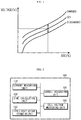
- Fig. 1 is a graph illustrating a battery cell voltage measured when a battery cell is in a charged state and a battery cell voltage measured when the battery cell is in a discharged state, in comparison with an open circuit voltage of the battery cell.
- the horizontal axis (x axis) represents the state of charge (SOC) of the battery cell
- the vertical axis (y axis) represents the voltage of the battery cell.
- the open circuit voltage (OCV) of the battery cell may be an indicator representing various characteristics of the battery cell, but in Fig. 1 , it is being used as an indicator representing the state of charge (SOC) of the battery cell. That is, if the open circuit voltage of the battery cell is available, it is possible to find out the state of charge (SOC) of the corresponding battery cell.
- Fig. 1 the voltage profile of a charged state displayed 'charged' and the voltage profile of a discharged state displayed 'discharged' are different from the open circuit voltage profile displayed 'OCV'. Therefore, the voltage of the battery cell measured during charging or discharging of the battery cell is different from the open circuit voltage.
- the applicant found out that the average value of the voltage of the battery cell obtained by measuring up until a time point where the integrated value of the voltage components adjusted due to the IR effect is zero(0) has a value very close to the average value of the open circuit voltage of the battery cell.
- Fig. 2 is a view illustrating a functional configuration of an open circuit voltage estimating apparatus according to an embodiment of the present disclosure
- Fig. 3 is a view illustrating a connection configuration inside a battery pack of an open circuit voltage estimating apparatus according to an embodiment of the present disclosure.
- the open circuit voltage estimating apparatus 100 includes a current measuring unit 110, a current integrating unit 120, a time calculating unit 130, a cell voltage measuring unit 140 and an open circuit voltage estimating unit 150.
- the current measuring unit 110 may measure a charge/discharge current of a battery cell C.
- the current measuring unit 110 may measure the current flowing via the battery cell C using various current measuring methods.
- the battery pack includes a battery assembly.
- the battery assembly means an assembly of two or more battery cells C, wherein the two or more battery cells C may be connected in series, in parallel, or in series-parallel.
- the current of the battery cell C may be measured by measuring the current flowing via the battery assembly or the current flowing on a charge/discharge route of the battery pack.
- a sense resistance R sense provided on the charge/discharge route of the battery pack, divide the measured voltage by a resistance value of the sense resistance R sense to obtain the current flowing on the charge/discharge route of the battery pack, and then, based on that current obtained, obtain the current flowing via the battery cell C.
- Such a current measuring method is merely an embodiment, that is, the present disclosure is not limited to the aforementioned current measuring method.
- the current integrating unit 120 may integrate the current measured by the current measuring unit 110 starting from an initial time.
- the initial time may be the time when integrating of the current starts.
- the current integrating unit 120 may sum the current continuously measured by the current measuring unit 110.
- the current integrating unit 120 may integrate the current discretely measured by the current measuring unit 110.
- a continuous current integrating operation starting from the initial time t1 to an arbitrary time t2 may be performed respectively using the Equation below.
- I(t) is the current continuously measured by the current measuring unit 110.
- the current integrating unit 120 may sum the continuously measured current by integrating I(t) over a section from t1 to t2.
- the time calculating unit 130 may calculate a time where the integrated current value integrated by the current integrating unit 120 is within a critical range.
- the time within a critical range may be called a critical time.
- V represents a dynamic voltage of the battery cell C
- OCV represents the open circuit voltage of the battery cell C
- I represents the current flowing through the battery cell C
- R represents the internal resistance of the battery cell C.
- V is a voltage of the battery cell C in which the effect caused by the internal resistance and the like is reflected. It can be said as the voltage value measured when measuring the voltage of the battery cell C.
- Equation 4 The average value obtained from Equation 2, that is, the average value of the dynamic voltage equals Equation 3 below, and Equation 3 may be represented as Equation 4.
- t 0 is the initial time.
- the average value of the open circuit voltage Avg(OCV) may be obtained by obtaining the average value of the dynamic voltage Avg(V). That is, when term ⁇ t 0 t 0 + T I t ⁇ R t dt T at the right side of Equation 4 is removed, the average value of the measurement value of the battery cell C equals the average value of the open circuit voltage.
- the average value of the open circuit voltage Avg(OCV) may be derived by measuring the voltage of the battery cell C and obtaining the average value of the measured voltage of the battery cell C for a time from the initial time to an operation time.
- Equation 6 when T that satisfies Equation 6 below is found, term ⁇ t 0 t 0 + T I t ⁇ R t dt T at the right side of Equation 4 can be removed.
- the average value of the open circuit voltage Avg(OCV) may be obtained by obtaining the average value of the dynamic voltage Avg(V).
- I 0 is a constant number for setting the critical range. It can be called a critical constant. That is, the critical range or the critical constant may be set to be in a range such that the integrated current value can be set close to 0 as an error range if not 0.
- the critical range or the critical constant may be set to be in a range such that the integrated current value can be set close to 0 as an error range if not 0.
- One skilled in the related art should be able to set an appropriate critical range or critical constant through experiments or simulations, etc.
- the time calculating unit 130 may calculate the time where the integrated current value integrated by the current integrating unit 120 is within the critical range.
- the critical time may be a value within a certain range.
- the time calculating unit 130 may calculate the critical time by selecting an arbitrary value from values included in the certain range.
- the time calculating unit 130 may calculate the time point where the integrated current value is 0 as the critical time. That is, the time calculating unit 130 may calculate t 0 +T that satisfies the Equation below as the critical time. In other words, the time calculating unit 130 may integrate the current starting from the initial time to and calculate the time point where the integrated current value is 0 as the critical time (t 0 +T).
- the time calculating unit 130 may calculate the time in which the mathematical symbol of the integrated current value changes as the critical time. That is, the time calculating unit 130 may calculate the time in which the magnitude of the integrated current value changes from a positive number + to a negative number -, or from a negative number - to a positive number + as the critical time.
- time calculating unit 130 may transmit the calculated critical time to an open circuit voltage estimating unit 150 that will be explained hereinafter.
- the cell voltage measuring unit 140 may measure a voltage of the battery cell C.
- the cell voltage measuring unit 140 may measure the voltage of the battery cell C by various well known voltage measuring methods.
- the cell voltage measuring unit 140 may measure the voltage of the plurality of battery cells C.
- the cell voltage measuring unit 140 may measure the voltage of each battery cell C by measuring the voltage at both ends of each battery cell C.
- the cell voltage measuring unit 140 may transmit the measured voltage of the battery cell C to the open circuit voltage estimating unit 150 that will be explained hereinafter.
- the open circuit voltage estimating unit 150 may calculate an average value of the voltage of the battery cell C measured by the cell voltage measuring unit 140.
- the open circuit voltage estimating unit 150 may obtain an arithmetic average value of the voltage of the battery cell C using the voltage of the battery cell C measured during a certain time.
- the certain time may be the operation time.
- the open circuit voltage estimating unit 150 may receive transmission of information on the operation time from the time calculating unit 130, and receive transmission of information on the voltage of the battery cell C from the cell voltage measuring unit 140.
- the open circuit voltage estimating unit 150 may calculate the average value of the voltage by integrating the cell voltage starting from the initial time to the critical time, that is, integrating the cell voltage during the operation time, and then dividing the integrated cell voltage by the operation time. That is, the open circuit voltage estimating unit 150 may calculate the average value of the voltage using the Equation below. ⁇ t 0 t 0 + T V t dt T
- the open circuit voltage estimating unit 150 may estimate the average value of the voltage calculated through the aforementioned method as the open circuit voltage of the battery cell C. Further, the open circuit voltage of the battery cell C estimated through the aforementioned method may be used for various purposes.
- the aforementioned open circuit voltage estimating apparatus 100 may be used in balancing. That is, a cell balancing apparatus 200 according to another aspect of the present disclosure may include the aforementioned open circuit voltage estimating apparatus 100.
- Fig. 4 is a view illustrating a cell balancing apparatus according to an embodiment of the present disclosure.
- the cell balancing apparatus 200 includes the aforementioned open circuit voltage estimating apparatus 100 and a balancing circuit 270, and further includes a balancing controlling unit 260 that connects the open circuit voltage estimating apparatus 100 and the balancing circuit 270.
- a balancing controlling unit 260 that connects the open circuit voltage estimating apparatus 100 and the balancing circuit 270.
- the explanation on the aforementioned open circuit voltage estimating apparatus 100 may be applied identically as it is, and thus repeated explanation will be omitted.
- the current measuring unit 210 may measure the current flowing through the battery cell C.
- the current measuring unit 210 adopts a method of measuring the current flowing on the charge/discharge route of the battery pack.
- the current integrating unit 220 may integrate the current measured by the current measuring unit 210 starting from the initial time.
- the time calculating unit 230 may calculate the critical time, that is the time where the integrated current value integrated by the current integrating unit 220 is within the critical range.
- the cell voltage measuring unit 240 may measure the voltage of the battery cell C.
- the open circuit voltage estimating unit 250 may calculate the average value of the voltage measured by the cell voltage measuring unit 240 for the time during the operation time. Further, the open circuit voltage estimating unit 250 may estimate the calculated average value of the voltage as the open circuit voltage of the battery cell C.
- the balancing controlling unit 260 controls the balancing circuit 270 using the open circuit voltage of the battery cell C estimated by the open circuit voltage estimating unit 250. That is, the balancing controlling unit 260 controls the balancing circuit 270 such that the deviation of the voltage of the plurality of battery cells C is reduced.
- the balancing circuit 270 is connected to each battery cell C to balance the voltage of each battery cell C.
- the balancing circuit 270 plays a role of decreasing or increasing the voltage of each battery cell C by way of control of the balancing controlling unit 260.
- the balancing circuit 270 may be realized as a charging circuit that charges the battery cell C to increase the voltage, or else, as a discharging circuit that discharges the battery cell C to decrease the voltage, or as a circuit configured in combination of the charging circuit and the discharging circuit.
- the balancing circuit 270 may be realized as a discharging circuit that includes a resistance element R B and a switch SW, as illustrated in Fig. 4 .
- the switch SW is an element that may be optionally turned-on or turned-off, for example, a field effect transistor (FET) element.
- FET field effect transistor
- the discharging circuit may be connected to each battery cell C in parallel.
- the balancing controlling unit 260 may control the switch SW to discharge the battery cell C. That is, the balancing controlling unit 260 may turn-on the switch SW connected to a battery cell C having a higher voltage than other battery cells C to decrease the voltage of the battery cell C.
- the aforementioned open circuit voltage estimating apparatus 100 may be included in a battery pack.
- a battery pack according to another aspect of the present disclosure may include the aforementioned open circuit voltage estimating apparatus 100.
- an energy storage system may include the aforementioned open circuit voltage estimating apparatus 100.
- the energy storage system may be an energy storage system (ESS) used in frequency regulation (FR) of power generation equipment.
- ESS energy storage system
- FR frequency regulation
- Such an energy storage system for frequency regulation performs charging/discharging continuously without any rest time, and thus may be regarded as an application suitable for the aforementioned open circuit voltage estimating apparatus 100 to be adopted.
- the open circuit voltage estimating method according to the another aspect of the present disclosure may be a method for estimating an open circuit voltage using the aforementioned open circuit voltage estimating apparatus 100, and the subject of each step that performs the open circuit voltage estimating method may be each configurative element of the aforementioned open circuit voltage estimating apparatus 100.
- Fig. 5 is a flowchart illustrating an open circuit voltage estimating method according to an embodiment of the present disclosure.
- the open circuit voltage estimating method measures a charge/discharge current of a battery cell C (S510).
- the current measured at the measuring step (S510) is integrated starting from the initial time (S520).
- a critical time that is the time where the integrated current value integrated at the current integrating step (S520) is within a critical range, is calculated (S530).
- the open circuit voltage estimating method may perform measurement of a voltage of the battery cell C together with the measurement of the charge/discharge current of the battery cell C (S540). That is, there is no order of time series between the current measurement (S510) and the voltage measurement (S540), but are performed independently.
- the open circuit voltage estimating method calculates the average value of the voltage measured at the step (S540) of measuring the voltage (S550).
- the calculated average value of the voltage is the average value of the voltage value measured during the time starting from the initial time until the critical time. In other words, it can be said as the average value of the voltage value measured during the operation time.
- the open circuit voltage estimating method calculates the average value of the voltage during the operation time (S550), and estimates the calculated average value of the voltage as the open circuit voltage (S560).
Landscapes
- Physics & Mathematics (AREA)
- General Physics & Mathematics (AREA)
- Engineering & Computer Science (AREA)
- Manufacturing & Machinery (AREA)
- Chemical & Material Sciences (AREA)
- Chemical Kinetics & Catalysis (AREA)
- Electrochemistry (AREA)
- General Chemical & Material Sciences (AREA)
- Power Engineering (AREA)
- Secondary Cells (AREA)
- Measurement Of Current Or Voltage (AREA)
Abstract
Description
- The present application claims the benefit of Korean Patent Application No.
10-2014-0150328 filed on October 31, 2014 - The present disclosure relates to a technology of managing a secondary battery, and more particularly, to a technology of estimating an open circuit voltage of the secondary battery necessary for monitoring and controlling performance of the secondary battery.
- Along with the recently increased demand for portable electronic products such as laptop computers, video cameras, mobile phones, and so on, the development of electric vehicles, energy storage batteries, robots, satellites, and so on started in earnest and led into active researches on high-performance secondary batteries capable of repeated charging and discharging.
- Currently, commercially available secondary batteries comprise nickel cadmium, nickel hydrogen, nickel zinc and lithium secondary batteries. Among them, lithium secondary batteries have drawn much attention because of little memory effect to allow unrestrained charging/discharging, as well as very low self-discharging rate and high energy density, compared to nickel-based secondary batteries.
- Meanwhile, there are cases where such a secondary battery is used in a single battery, but in many cases, the secondary battery is used in a state where a plurality of the secondary batteries are connected in series and/or in parallel so as to be used in a high voltage and/or mass energy storage apparatus. Further, the secondary battery is generally used in the form of a battery pack or a battery system that includes a plurality of battery cells and a battery management apparatus configured to control overall charge/discharge operations of the battery cells.
- Further, such a battery management apparatus used in the battery pack performs the function of monitoring a state of the battery using a temperature sensor, a current sensor, a voltage sensor and the like and using results of such monitoring to estimate a state of charge (SOC) or a state of health (SOH) or to balance a voltage between the battery cells, or to protect the battery from high voltage, overcurrent, low temperature and high temperature, etc.
- Meanwhile, in many cases, a conventional battery management apparatus measures and uses an open circuit voltage (OCV) of the battery cell in order to perform the management functions such as estimating the state of charge (SOC), estimating the state of health (SOH) and cell balancing, etc. The open circuit voltage of a battery cell refers to the voltage of the battery cell in a state where an external load or an external circuit is not connected or in a stabilized state where a charge/discharge operation of the battery cell is not performed. Here, the reason why the open circuit voltage of the battery cell is different from the actual voltage measured from the battery cell is known to be because of internal resistance (ohmic polarization) of the cell and the polarization phenomenon and the like related to movements of electrons in an electrode/electrolyte interface.
- But, in order to measure an exact open circuit voltage, it is necessary to stop using the battery cell, and sufficient time must lapse prior to making the measurement. That is, in order to measure the exact open circuit voltage, the battery cell needs to be in a non-charged/discharged state.
- However, in many cases, information on an open circuit voltage is required in real time in the process of charging/discharging. Further, depending on the type of apparatus where the battery is being applied, there are cases where charging/discharging continues without any non-operation period of the battery. For example, an energy storage system (ESS) used in frequency regulation of power generation equipment performs charging/discharging continuously without a rest time. Therefore, in the case of a battery used in such an apparatus, there is a problem that it is difficult to measure the open circuit voltage.
- (Prior art document) Korean Laid-open Patent no.
10-2009-0020470 - The present disclosure is designed to solve the problems of the related art, and therefore the present disclosure is directed to providing an open circuit voltage estimating apparatus capable of estimating an open circuit voltage even when the battery cell does not have a rest time.
- The other objectives and advantages of the present disclosure can be understood with the following description and more clearly with the embodiments of the present disclosure. Also, it should easily be understood that the other objectives and advantages of the present disclosure can be implemented by the means described in the claims and the combinations thereof.
- The applicant became aware of the aforementioned problems and found out while continuously conducting researches thereon that an open circuit voltage of a battery cell follows the charge/discharge voltage of the battery cell, and that removing from the voltage of the battery cell a voltage component adjusted due to the IR effect caused by internal resistance results in a value that is very close to the open circuit voltage of the battery cell.
- Based on the aforementioned, the applicant came up with a technology of measuring the voltage of the battery cell until a (+) voltage component being integrated due to the IR effect as the battery cell is charged and a (-) voltage component being subtracted due to the IR effect as the battery cell is discharged offset each other, and estimating an average value of the voltage of the battery cell measured until the offset as the open circuit voltage of the battery cell.
- Various embodiments of the present disclosure for achieving the aforementioned purposes are as follows.
- (1). An open circuit voltage estimating apparatus including: a current measuring unit configured to measure a charge/discharge current of a battery cell; a current integrating unit configured to integrate the current measured by the current measuring unit starting from an initial time; a time calculating unit configured to calculate a critical time, that is a time where the integrated current value integrated by the current integrating unit is within a critical range; a cell voltage measuring unit configured to measure a voltage of the battery cell; and an open circuit voltage estimating unit configured to estimate an open circuit voltage of the battery cell by calculating an average value of the voltage measured by the cell voltage measuring unit during an operation time starting from the initial time until the critical time.
- (2). In (1), the time calculating unit may calculate a time point in which the integrated current value is 0, as the critical time.
- (3). In (1), the time calculating unit may calculate a time where a mathematical symbol of the integrated current value changes, as the critical time.
- (4). In any one of (1) to (3), the open circuit voltage estimating unit may calculate the average value of the voltage by integrating a cell voltage for a time during the operation time and dividing the integrated cell voltage by the operation time.
- (5). A cell balancing apparatus including: the open circuit voltage estimating apparatus of any one of (1) to (4); and a balancing circuit configured to perform balancing between battery cells included in a battery assembly using an open circuit voltage estimated by the open circuit voltage estimating apparatus.
- (6). A battery pack including the open circuit voltage estimating apparatus of any one of (1) to (4).
- (7). An energy storage system including the open circuit voltage estimating apparatus of any one of (1) to (4). The energy storage system may be an energy storage system for frequency adjustment being used in frequency adjustment of power generation equipment.
- (8). An open circuit voltage estimating method including: measuring a charge/discharge current of a battery cell; integrating the current measured at the measuring step starting from an initial time; calculating a critical time, that is a time in which the integrated current value integrated at the current integrating step is within a critical range; measuring a voltage of the battery cell; and estimating an open circuit voltage of the battery cell by calculating an average value of the voltage measured at the voltage measuring step during an operation time starting from the initial time until the critical time, and estimating the calculated average value of the voltage as the open circuit voltage of the battery cell.
- (9). In (8), the critical time calculating step may calculate a time point in which the integrated current value is 0, as the critical time.
- (10). In (8), the operation time calculating step may calculate a time in which a mathematical symbol of the integrated current value changes, as the critical time.
- (11). In any one of (8) to (10), the open circuit voltage estimating step may calculate the average value of the voltage by integrating a cell voltage for a time during the operation time and dividing the integrated cell voltage by the operation time.
- The present disclosure gives the following effects.
- According to the present disclosure, it is possible to estimate an open circuit voltage of a battery cell while charging/discharging of the battery cell continues. Therefore, according to the present disclosure, it is possible to estimate an open circuit voltage of a battery applied to an application that does not have a rest time.
- According to an aspect of the present disclosure, it is possible to estimate an open circuit voltage of a battery cell, and perform balancing between the battery cells using the estimated open circuit voltage. By doing this, it is possible to prevent beforehand accidents that may occur due to voltage deviation or SOC deviation between battery cells.
- The present disclosure can provide a variety of effects other than those mentioned above, which will become apparent from the following descriptions and further elucidated from the embodiments of the present disclosure.
- Other objects and aspects of the present disclosure will become apparent from the following descriptions of the embodiments with reference to the accompanying drawings in which:
- The accompanying drawings illustrate preferred embodiments of the present disclosure and, together with the foregoing disclosure, serve to provide further understanding of the technical features of the present disclosure. However, the present disclosure is not to be construed as being limited to the drawings.
-
Fig. 1 is a graph illustrating a battery cell voltage measured when a battery cell is in a charged state and a battery cell voltage measured when the battery cell is in a discharged state, in comparison with an open circuit voltage of the battery cell. -
Fig. 2 is a view illustrating a functional configuration of an open circuit voltage estimating apparatus according to an embodiment of the present disclosure. -
Fig. 3 is a view illustrating a connection configuration inside a battery pack of an open circuit voltage estimating apparatus according to an embodiment of the present disclosure. -
Fig. 4 is a view illustrating a cell balancing apparatus according to an embodiment of the present disclosure. -
Fig. 5 is a flowchart illustrating an open circuit voltage estimating method according to an embodiment of the present disclosure.
-
- Hereinafter, preferred embodiments of the present disclosure will be described in detail with reference to the accompanying drawings. Prior to the description, it should be understood that the terms used in the specification and the appended claims should not be construed as limited to general and dictionary meanings, but interpreted based on the meanings and concepts corresponding to technical aspects of the present disclosure on the basis of the principle that the inventor is allowed to define terms appropriately for the best explanation. Therefore, the embodiments disclosed in the present specification and the configurations illustrated in the drawings are merely the most preferred embodiments of the present disclosure, and not all of them represent the technical ideas of the present disclosure, and thus it should be understood that there may be various equivalents and modified examples that could substitute therefor at the time of filing the present application.
- Further, in explaining the present disclosure, any specific explanation on a well-known related configuration or function deemed to obscure the gist of the present disclosure will be omitted.
- Prior to explaining an open circuit voltage estimating apparatus according to an aspect of the present disclosure, voltage change behavior of a battery cell caused by charging/discharging of the battery cell will be explained.
-
Fig. 1 is a graph illustrating a battery cell voltage measured when a battery cell is in a charged state and a battery cell voltage measured when the battery cell is in a discharged state, in comparison with an open circuit voltage of the battery cell. - In
Fig. 1 , the horizontal axis (x axis) represents the state of charge (SOC) of the battery cell, and the vertical axis (y axis) represents the voltage of the battery cell. The open circuit voltage (OCV) of the battery cell may be an indicator representing various characteristics of the battery cell, but inFig. 1 , it is being used as an indicator representing the state of charge (SOC) of the battery cell. That is, if the open circuit voltage of the battery cell is available, it is possible to find out the state of charge (SOC) of the corresponding battery cell. - However, as aforementioned in [BACKGROUND ART], the voltage of a battery cell measured in a state the battery cell is being charged or discharged is different from the open circuit voltage of the battery cell, and it is not easy to estimate the open circuit voltage of the battery cell during charging or discharging of the battery cell.
- This can be understood easily with reference to
Fig. 1 . InFig. 1 , the voltage profile of a charged state displayed 'charged' and the voltage profile of a discharged state displayed 'discharged' are different from the open circuit voltage profile displayed 'OCV'. Therefore, the voltage of the battery cell measured during charging or discharging of the battery cell is different from the open circuit voltage. - However, the applicant found out, as aforementioned, that removing from the voltage of the battery cell a voltage component adjusted due to the IR effect caused by internal resistance results in a value that is very close to the open circuit voltage of the battery cell.
- Further, the applicant became aware that although the internal resistance of a battery cell is a variant that changes over time (time variant), it can be regarded as a constant number that does not depend on change of time during a relatively short period of time. Therefore, the applicant became aware that it is possible to integrate the voltage components adjusted due to the IR effect by measuring the value of the current flowing via the battery cell and integrating the measured current values. By doing this, the applicant became aware that it is easy to find a case where the integrated value of the voltage components adjusted due to the IR effect is 0, that is, where the state of charge and the state of discharge of the battery cell are substantially the same.
- Based on this knowledge, the applicant found out that the average value of the voltage of the battery cell obtained by measuring up until a time point where the integrated value of the voltage components adjusted due to the IR effect is zero(0) has a value very close to the average value of the open circuit voltage of the battery cell.
- Further, the applicant found out that even when the average value of the open circuit voltage is used as the open circuit voltage of the battery cell at a certain time point, the error is not so big. Moreover, the applicant found out that in the case of a battery used in an application that continuously repeats charging/discharging, such an error value is small enough to be disregarded.
- Hereinafter, an open circuit voltage estimating apparatus according to one aspect of the present disclosure will be explained.
-
Fig. 2 is a view illustrating a functional configuration of an open circuit voltage estimating apparatus according to an embodiment of the present disclosure, andFig. 3 is a view illustrating a connection configuration inside a battery pack of an open circuit voltage estimating apparatus according to an embodiment of the present disclosure. - Referring to
Fig. 2 andFig. 3 , the open circuitvoltage estimating apparatus 100 according to an embodiment of the present disclosure includes acurrent measuring unit 110, a current integratingunit 120, atime calculating unit 130, a cellvoltage measuring unit 140 and an open circuitvoltage estimating unit 150. - The
current measuring unit 110 may measure a charge/discharge current of a battery cell C. Thecurrent measuring unit 110 may measure the current flowing via the battery cell C using various current measuring methods. - Referring to
Fig. 3 , the battery pack includes a battery assembly. Here, the battery assembly means an assembly of two or more battery cells C, wherein the two or more battery cells C may be connected in series, in parallel, or in series-parallel. As illustrated inFig. 3 , in the case of a battery assembly configured by connecting battery cells C in series, the current of the battery cell C may be measured by measuring the current flowing via the battery assembly or the current flowing on a charge/discharge route of the battery pack. - For example, as illustrated in
Fig. 3 , it is possible to measure the voltage at both ends of a sense resistance Rsense provided on the charge/discharge route of the battery pack, divide the measured voltage by a resistance value of the sense resistance Rsense to obtain the current flowing on the charge/discharge route of the battery pack, and then, based on that current obtained, obtain the current flowing via the battery cell C. - Meanwhile, such a current measuring method is merely an embodiment, that is, the present disclosure is not limited to the aforementioned current measuring method.
- The current integrating
unit 120 may integrate the current measured by thecurrent measuring unit 110 starting from an initial time. Here, the initial time may be the time when integrating of the current starts. - For example, the current integrating
unit 120 may sum the current continuously measured by thecurrent measuring unit 110. In another example, the current integratingunit 120 may integrate the current discretely measured by thecurrent measuring unit 110. According to an embodiment, a continuous current integrating operation starting from the initial time t1 to an arbitrary time t2 may be performed respectively using the Equation below.
- Here, I(t) is the current continuously measured by the
current measuring unit 110. The current integratingunit 120 according to an embodiment of the present disclosure may sum the continuously measured current by integrating I(t) over a section from t1 to t2. - The
time calculating unit 130 may calculate a time where the integrated current value integrated by the current integratingunit 120 is within a critical range. Here, the time within a critical range may be called a critical time. - The critical range may be set to be the range where the integrated current value is close to 0. That is, the critical range may be set to be the range where the sum of the charging current and the discharging current of the battery cell C is close to 0. In other words, the critical range may be set to be the range where the charging current and the discharging current of the battery cell C offset each other. Setting the critical range as aforementioned is for offsetting the error between the actually measured voltage and the open circuit voltage caused by internal resistance and the like. This can be understood based on the Equations below.

- Here, V represents a dynamic voltage of the battery cell C, OCV represents the open circuit voltage of the battery cell C, I represents the current flowing through the battery cell C, and R represents the internal resistance of the battery cell C. Further, the dynamic voltage V is a voltage of the battery cell C in which the effect caused by the internal resistance and the like is reflected. It can be said as the voltage value measured when measuring the voltage of the battery cell C.
- The average value obtained from Equation 2, that is, the average value of the dynamic voltage equals Equation 3 below, and Equation 3 may be represented as Equation 4.


- Here, t0 is the initial time. Here, when term


- Meanwhile, R(t) at the right side of Equation 4 representing the internal resistance may be treated as a constant number that does not depend on change of time provided that the time is sufficiently short. That is, R(t) may be treated as R. Therefore, term


- Therefore, when T that satisfies Equation 6 below is found, term


- In other words, when the integrated current value is 0 or close to 0, term

- Further, whether or not the integrated current value is close to 0 as aforementioned may be determined based on the Equation below.

- Here, I0 is a constant number for setting the critical range. It can be called a critical constant. That is, the critical range or the critical constant may be set to be in a range such that the integrated current value can be set close to 0 as an error range if not 0. One skilled in the related art should be able to set an appropriate critical range or critical constant through experiments or simulations, etc.
- The
time calculating unit 130 may calculate the time where the integrated current value integrated by the current integratingunit 120 is within the critical range. Here, the critical time may be a value within a certain range. Thetime calculating unit 130 may calculate the critical time by selecting an arbitrary value from values included in the certain range. - Optically, the
time calculating unit 130 may calculate the time point where the integrated current value is 0 as the critical time. That is, thetime calculating unit 130 may calculate t0+T that satisfies the Equation below as the critical time. In other words, thetime calculating unit 130 may integrate the current starting from the initial time to and calculate the time point where the integrated current value is 0 as the critical time (t0+T). Here, the operation time may be T, that is the difference between the critical time and the initial time.
- Further optionally, the
time calculating unit 130 may calculate the time in which the mathematical symbol of the integrated current value changes as the critical time. That is, thetime calculating unit 130 may calculate the time in which the magnitude of the integrated current value changes from a positive number + to a negative number -, or from a negative number - to a positive number + as the critical time. - Further, the
time calculating unit 130 may transmit the calculated critical time to an open circuitvoltage estimating unit 150 that will be explained hereinafter. - The cell
voltage measuring unit 140 may measure a voltage of the battery cell C. The cellvoltage measuring unit 140 may measure the voltage of the battery cell C by various well known voltage measuring methods. - For example, as illustrated in
Fig. 3 , in the case where the battery pack includes a battery assembly consisting of a plurality of battery cells C, the cellvoltage measuring unit 140 may measure the voltage of the plurality of battery cells C. Here, the cellvoltage measuring unit 140 may measure the voltage of each battery cell C by measuring the voltage at both ends of each battery cell C. - Further, the cell
voltage measuring unit 140 may transmit the measured voltage of the battery cell C to the open circuitvoltage estimating unit 150 that will be explained hereinafter. - The open circuit
voltage estimating unit 150 may calculate an average value of the voltage of the battery cell C measured by the cellvoltage measuring unit 140. Here, the open circuitvoltage estimating unit 150 may obtain an arithmetic average value of the voltage of the battery cell C using the voltage of the battery cell C measured during a certain time. Here, the certain time may be the operation time. For this purpose, the open circuitvoltage estimating unit 150 may receive transmission of information on the operation time from thetime calculating unit 130, and receive transmission of information on the voltage of the battery cell C from the cellvoltage measuring unit 140. - According to an embodiment, the open circuit
voltage estimating unit 150 may calculate the average value of the voltage by integrating the cell voltage starting from the initial time to the critical time, that is, integrating the cell voltage during the operation time, and then dividing the integrated cell voltage by the operation time. That is, the open circuitvoltage estimating unit 150 may calculate the average value of the voltage using the Equation below.
- The open circuit
voltage estimating unit 150 may estimate the average value of the voltage calculated through the aforementioned method as the open circuit voltage of the battery cell C. Further, the open circuit voltage of the battery cell C estimated through the aforementioned method may be used for various purposes. - According to another aspect of the present disclosure, the aforementioned open circuit
voltage estimating apparatus 100 may be used in balancing. That is, acell balancing apparatus 200 according to another aspect of the present disclosure may include the aforementioned open circuitvoltage estimating apparatus 100. -
Fig. 4 is a view illustrating a cell balancing apparatus according to an embodiment of the present disclosure. - Referring to
Fig. 4 , thecell balancing apparatus 200 according to an embodiment of the present disclosure includes the aforementioned open circuitvoltage estimating apparatus 100 and abalancing circuit 270, and further includes abalancing controlling unit 260 that connects the open circuitvoltage estimating apparatus 100 and thebalancing circuit 270. Here, regarding the present open circuitvoltage estimating apparatus 100, the explanation on the aforementioned open circuitvoltage estimating apparatus 100 may be applied identically as it is, and thus repeated explanation will be omitted. - The
current measuring unit 210 may measure the current flowing through the battery cell C. In the present embodiment, thecurrent measuring unit 210 adopts a method of measuring the current flowing on the charge/discharge route of the battery pack. - The current integrating
unit 220 may integrate the current measured by thecurrent measuring unit 210 starting from the initial time. - The
time calculating unit 230 may calculate the critical time, that is the time where the integrated current value integrated by the current integratingunit 220 is within the critical range. - The cell
voltage measuring unit 240 may measure the voltage of the battery cell C. - The open circuit
voltage estimating unit 250 may calculate the average value of the voltage measured by the cellvoltage measuring unit 240 for the time during the operation time. Further, the open circuitvoltage estimating unit 250 may estimate the calculated average value of the voltage as the open circuit voltage of the battery cell C. - The
balancing controlling unit 260 controls thebalancing circuit 270 using the open circuit voltage of the battery cell C estimated by the open circuitvoltage estimating unit 250. That is, thebalancing controlling unit 260 controls thebalancing circuit 270 such that the deviation of the voltage of the plurality of battery cells C is reduced. - The
balancing circuit 270 is connected to each battery cell C to balance the voltage of each battery cell C.The balancing circuit 270 plays a role of decreasing or increasing the voltage of each battery cell C by way of control of thebalancing controlling unit 260. Thebalancing circuit 270 may be realized as a charging circuit that charges the battery cell C to increase the voltage, or else, as a discharging circuit that discharges the battery cell C to decrease the voltage, or as a circuit configured in combination of the charging circuit and the discharging circuit. According to an embodiment, thebalancing circuit 270 may be realized as a discharging circuit that includes a resistance element RB and a switch SW, as illustrated inFig. 4 . Here, the switch SW is an element that may be optionally turned-on or turned-off, for example, a field effect transistor (FET) element. - The discharging circuit may be connected to each battery cell C in parallel.
- In such an embodiment, the
balancing controlling unit 260 may control the switch SW to discharge the battery cell C. That is, thebalancing controlling unit 260 may turn-on the switch SW connected to a battery cell C having a higher voltage than other battery cells C to decrease the voltage of the battery cell C. - According to another aspect of the present disclosure, the aforementioned open circuit
voltage estimating apparatus 100 may be included in a battery pack. In other words, a battery pack according to another aspect of the present disclosure may include the aforementioned open circuitvoltage estimating apparatus 100. - Further, an energy storage system according to another aspect of the present disclosure may include the aforementioned open circuit
voltage estimating apparatus 100. Optionally, the energy storage system may be an energy storage system (ESS) used in frequency regulation (FR) of power generation equipment. Such an energy storage system for frequency regulation performs charging/discharging continuously without any rest time, and thus may be regarded as an application suitable for the aforementioned open circuitvoltage estimating apparatus 100 to be adopted. - Hereinafter, an open circuit voltage estimating method according to another aspect of the present disclosure will be explained. The open circuit voltage estimating method according to the another aspect of the present disclosure may be a method for estimating an open circuit voltage using the aforementioned open circuit
voltage estimating apparatus 100, and the subject of each step that performs the open circuit voltage estimating method may be each configurative element of the aforementioned open circuitvoltage estimating apparatus 100. -
Fig. 5 is a flowchart illustrating an open circuit voltage estimating method according to an embodiment of the present disclosure. - Referring to
Fig. 5 , first of all, the open circuit voltage estimating method according to an embodiment of the present disclosure measures a charge/discharge current of a battery cell C (S510). Next, the current measured at the measuring step (S510) is integrated starting from the initial time (S520). Next, a critical time, that is the time where the integrated current value integrated at the current integrating step (S520) is within a critical range, is calculated (S530). - Meanwhile, the open circuit voltage estimating method according to an embodiment of the present disclosure may perform measurement of a voltage of the battery cell C together with the measurement of the charge/discharge current of the battery cell C (S540). That is, there is no order of time series between the current measurement (S510) and the voltage measurement (S540), but are performed independently.
- Further, the open circuit voltage estimating method according to an embodiment of the present disclosure calculates the average value of the voltage measured at the step (S540) of measuring the voltage (S550). Here, the calculated average value of the voltage is the average value of the voltage value measured during the time starting from the initial time until the critical time. In other words, it can be said as the average value of the voltage value measured during the operation time. The open circuit voltage estimating method according to an embodiment of the present disclosure calculates the average value of the voltage during the operation time (S550), and estimates the calculated average value of the voltage as the open circuit voltage (S560).
- The present disclosure has been described in detail. However, it should be understood that the detailed description and specific examples, while indicating preferred embodiments of the disclosure, are given by way of illustration only, and various changes and modifications within the scope of the disclosure will become apparent to those skilled in the art from this detailed description.
- Meanwhile, it is apparent to one skilled in the related art that although the term '∼unit' is used in the present specification, this terms represents a logical configurative unit, and thus does not represent a configurative element that must be physically separated from other configurative units, and each configurative unit must not necessarily be physically realized by one element or device.
- The characteristics described in the individual embodiments of the present disclosure may be implemented in combination into one single embodiment. In contrast, a variety of characteristics described herein as a single embodiment may be individually implemented in a variety of embodiments, or implemented in a proper subcombination.
Claims (11)
- An open circuit voltage estimating apparatus comprising:a current measuring unit configured to measure a charge/discharge current of a battery cell;a current integrating unit configured to integrate the current measured by the current measuring unit starting from an initial time;a time calculating unit configured to calculate a critical time, that is a time where the integrated current value integrated by the current integrating unit is within a critical range;a cell voltage measuring unit configured to measure a voltage of the battery cell; andan open circuit voltage estimating unit configured to estimate an open circuit voltage of the battery cell by calculating an average value of the voltage measured by the cell voltage measuring unit during an operation time starting from the initial time until the critical time.
- The open circuit voltage estimating apparatus of claim 1, wherein the time calculating unit calculates a time point in which the integrated current value is 0 as the critical time.
- The open circuit voltage estimating apparatus of claim 1, wherein the time calculating unit calculates a time where a mathematical symbol of the integrated current value changes as the critical time.
- The open circuit voltage estimating apparatus of any one of claims 1 to 3, wherein the open circuit voltage estimating unit calculates the average value of the voltage by integrating a cell voltage for a time during the operation time and dividing the integrated cell voltage by the operation time.
- A cell balancing apparatus comprising:the open circuit voltage estimating apparatus of any one of claims 1 to 4; anda balancing circuit configured to perform balancing between battery cells included in a battery assembly using an open circuit voltage estimated by the open circuit voltage estimating apparatus.
- A battery pack comprising the open circuit voltage estimating apparatus of any one of claims 1 to 4.
- An energy storage system comprising the open circuit voltage estimating apparatus of any one of claims 1 to 4.
- An open circuit voltage estimating method comprising:measuring a charge/discharge current of a battery cell;integrating the current measured at the measuring step starting from an initial time;calculating a critical time, that is a time in which the integrated current value integrated at the current integrating step is within a critical range;measuring a voltage of the battery cell; andestimating an open circuit voltage of the battery cell by calculating an average value of the voltage measured at the voltage measuring step during an operation time starting from the initial time until the critical time.
- The open circuit voltage estimating method of claim 8, wherein the critical time calculating step calculates a time point in which the integrated current value is 0 as the critical time.
- The open circuit voltage estimating method of claim 8, wherein the operation time calculating step calculates a time in which a mathematical symbol of the integrated current value changes, as the critical time.
- The open circuit voltage estimating method of any one of claims 8 to 10, wherein the open circuit voltage estimating step calculates the average value of the voltage by integrating a cell voltage for a time during the operation time and dividing the integrated cell voltage by the operation time.
Applications Claiming Priority (2)
| Application Number | Priority Date | Filing Date | Title |
|---|---|---|---|
| KR1020140150328A KR101783919B1 (en) | 2014-10-31 | 2014-10-31 | Apparatus and method for estimating open circuit voltage |
| PCT/KR2015/011590 WO2016068652A2 (en) | 2014-10-31 | 2015-10-30 | Open circuit voltage estimating device and method |
Publications (3)
| Publication Number | Publication Date |
|---|---|
| EP3141919A2 true EP3141919A2 (en) | 2017-03-15 |
| EP3141919A4 EP3141919A4 (en) | 2018-01-10 |
| EP3141919B1 EP3141919B1 (en) | 2020-09-16 |
Family
ID=55858500
Family Applications (1)
| Application Number | Title | Priority Date | Filing Date |
|---|---|---|---|
| EP15855064.0A Active EP3141919B1 (en) | 2014-10-31 | 2015-10-30 | Apparatus and method for estimating open circuit voltage |
Country Status (5)
| Country | Link |
|---|---|
| US (1) | US10018683B2 (en) |
| EP (1) | EP3141919B1 (en) |
| KR (1) | KR101783919B1 (en) |
| CN (1) | CN106471386B (en) |
| WO (1) | WO2016068652A2 (en) |
Families Citing this family (13)
| Publication number | Priority date | Publication date | Assignee | Title |
|---|---|---|---|---|
| US11437827B2 (en) * | 2016-03-01 | 2022-09-06 | Volvo Truck Corporation | Control of a relatively low current fed to a battery pack |
| KR102066702B1 (en) * | 2017-01-02 | 2020-03-02 | 주식회사 엘지화학 | Battery management apparatus and soc calibrating method using the same |
| KR101998069B1 (en) * | 2017-06-23 | 2019-07-09 | 이정환 | Method and apparatus for fast charging and maximum discharging with less-degradation of battery for an electric car |
| KR102236384B1 (en) | 2017-10-27 | 2021-04-05 | 주식회사 엘지화학 | Apparatus for battery balancing and battery pack including the same |
| KR102244140B1 (en) * | 2017-12-21 | 2021-04-22 | 주식회사 엘지화학 | Method and apparatus for calibrating state of charge of a battery |
| KR102055850B1 (en) * | 2017-12-21 | 2019-12-13 | 주식회사 엘지화학 | Apparatus and method for diagnosing fault of current sensor |
| KR102458526B1 (en) | 2018-02-07 | 2022-10-25 | 주식회사 엘지에너지솔루션 | Apparatus and method for estimating soc base on operating state of battery |
| CN109148981B (en) * | 2018-07-13 | 2020-05-08 | 东软集团股份有限公司 | Method and device for determining open-circuit voltage of battery, storage medium and electronic equipment |
| KR102443667B1 (en) * | 2018-10-26 | 2022-09-14 | 주식회사 엘지에너지솔루션 | balancing apparatus, and battery management system and battery pack including the same |
| CN112698225B (en) | 2019-10-22 | 2022-05-13 | 华为技术有限公司 | Battery capacity tracking method and device and electronic equipment |
| KR102786688B1 (en) * | 2020-07-24 | 2025-03-25 | 주식회사 엘지에너지솔루션 | Fault cell diagnosis method and battery system using the same |
| CN113708449B (en) * | 2021-08-24 | 2024-12-24 | 绵阳天仪空间科技有限公司 | A satellite battery module system |
| KR102716915B1 (en) * | 2023-04-21 | 2024-10-15 | 대흥시스텍주식회사 | Apparatus of impedance and open-circuit voltage measurement for secondary batteries |
Family Cites Families (17)
| Publication number | Priority date | Publication date | Assignee | Title |
|---|---|---|---|---|
| JP3121732B2 (en) * | 1994-11-04 | 2001-01-09 | 三菱電機株式会社 | Secondary battery parameter measurement method, secondary battery charge / discharge control method and life prediction method using the same, secondary battery charge / discharge control device, and power storage device using the same |
| JP2002189066A (en) * | 2000-12-22 | 2002-07-05 | Hitachi Ltd | Battery level estimation method |
| JP4457781B2 (en) | 2004-07-02 | 2010-04-28 | 新神戸電機株式会社 | Deterioration degree estimation method and deterioration degree estimation apparatus |
| US7233128B2 (en) | 2004-07-30 | 2007-06-19 | Ford Global Technologies, Llc | Calculation of state of charge offset using a closed integral method |
| KR100956172B1 (en) * | 2005-01-27 | 2010-05-06 | 파나소닉쿠 이브이에나지 가부시키가이샤 | Method and apparatus for estimating charge / discharge electricity of secondary battery, method and apparatus for estimating polarization voltage of secondary battery, and method and apparatus for estimating remaining capacity of secondary battery |
| KR100717789B1 (en) * | 2005-07-29 | 2007-05-11 | 삼성에스디아이 주식회사 | Calculation method of battery remaining capacity of secondary battery module |
| JP5077513B2 (en) | 2005-12-26 | 2012-11-21 | スズキ株式会社 | Device for estimating open-circuit voltage of vehicle battery |
| KR100985667B1 (en) | 2007-08-22 | 2010-10-05 | 주식회사 엘지화학 | Battery open circuit voltage estimator, battery charge state estimator and its control method |
| JP2012132726A (en) | 2010-12-20 | 2012-07-12 | Daimler Ag | Battery internal-resistance calculation method and battery internal-resistance calculation device |
| JP5318128B2 (en) | 2011-01-18 | 2013-10-16 | カルソニックカンセイ株式会社 | Battery charge rate estimation device |
| DE112012001144B4 (en) * | 2011-03-07 | 2025-10-02 | A123 Systems, LLC | Method for opportunistic balancing of charge between battery cells |
| JP5743634B2 (en) * | 2011-03-25 | 2015-07-01 | Necエナジーデバイス株式会社 | Deterioration measuring device, secondary battery pack, deterioration measuring method, and program |
| JP5866987B2 (en) * | 2011-11-10 | 2016-02-24 | 日産自動車株式会社 | Secondary battery control device and SOC detection method |
| JP5911407B2 (en) * | 2012-09-18 | 2016-04-27 | カルソニックカンセイ株式会社 | Battery soundness calculation device and soundness calculation method |
| JP5673654B2 (en) * | 2012-11-16 | 2015-02-18 | トヨタ自動車株式会社 | Power storage system and full charge capacity calculation method |
| KR102082866B1 (en) * | 2013-04-18 | 2020-04-14 | 삼성에스디아이 주식회사 | Battery management system and driving method thereof |
| KR20150029204A (en) * | 2013-09-09 | 2015-03-18 | 삼성에스디아이 주식회사 | Battery pack, apparatus including battery pack, and method of managing battery pack |
-
2014
- 2014-10-31 KR KR1020140150328A patent/KR101783919B1/en active Active
-
2015
- 2015-10-30 WO PCT/KR2015/011590 patent/WO2016068652A2/en not_active Ceased
- 2015-10-30 CN CN201580033536.6A patent/CN106471386B/en active Active
- 2015-10-30 EP EP15855064.0A patent/EP3141919B1/en active Active
- 2015-10-30 US US15/315,583 patent/US10018683B2/en active Active
Also Published As
| Publication number | Publication date |
|---|---|
| WO2016068652A2 (en) | 2016-05-06 |
| EP3141919A4 (en) | 2018-01-10 |
| WO2016068652A3 (en) | 2016-06-23 |
| KR20160051007A (en) | 2016-05-11 |
| CN106471386A (en) | 2017-03-01 |
| CN106471386B (en) | 2019-03-19 |
| US10018683B2 (en) | 2018-07-10 |
| KR101783919B1 (en) | 2017-10-10 |
| EP3141919B1 (en) | 2020-09-16 |
| US20170199250A1 (en) | 2017-07-13 |
Similar Documents
| Publication | Publication Date | Title |
|---|---|---|
| EP3141919B1 (en) | Apparatus and method for estimating open circuit voltage | |
| EP3444888B1 (en) | Apparatus and method for managing battery | |
| US10873201B2 (en) | Battery management apparatus and method for protecting a lithium iron phosphate cell from over-voltage using the same | |
| EP3664247B1 (en) | Charging time computation method and charge control device | |
| EP3130932B1 (en) | Insulation resistance measuring device and method capable of rapidly measuring insulation resistance | |
| EP1798100B1 (en) | Battery management system | |
| CN106716162B (en) | Battery state estimation device and power supply device | |
| EP3410558A1 (en) | Battery control device | |
| US20130187611A1 (en) | Cell voltage equalizer for multi-cell battery pack | |
| CN105051559B (en) | State of charge estimation device for secondary battery and method for estimating state of charge of secondary battery | |
| CN104051810B (en) | A kind of lithium-ion energy storage battery system SOC estimates rapid correction method | |
| JP2023015089A (en) | Rechargeable battery abnormality detection device and rechargeable battery abnormality detection method | |
| US20140239914A1 (en) | Battery controller | |
| KR101738601B1 (en) | Apparatus for estimating battery's state of health | |
| US20150293181A1 (en) | Secondary battery tester | |
| EP2731165A1 (en) | Method for manufacturing battery pack and battery pack | |
| US20160245870A2 (en) | Apparatus and method for estimating power storage device degradation | |
| KR20180031206A (en) | Battery management system and method for protecting a battery from over-discharge | |
| EP4571339B1 (en) | Battery management system, battery pack, electric vehicle, and battery management method | |
| CN108780931A (en) | Lithium-ion secondary battery life estimation device | |
| KR20170142451A (en) | Battery management system, battery pack and method for charging battery | |
| KR101277733B1 (en) | Apparatus and method for estimating state of charge of battery | |
| EP3323665B1 (en) | A battery pack balancing system and method | |
| KR101967863B1 (en) | Device and method of balancing requirement time estimation in high voltage cell balancing | |
| US20250355049A1 (en) | Estimation device, energy storage apparatus, estimation method, and program |
Legal Events
| Date | Code | Title | Description |
|---|---|---|---|
| STAA | Information on the status of an ep patent application or granted ep patent |
Free format text: STATUS: THE INTERNATIONAL PUBLICATION HAS BEEN MADE |
|
| PUAI | Public reference made under article 153(3) epc to a published international application that has entered the european phase |
Free format text: ORIGINAL CODE: 0009012 |
|
| STAA | Information on the status of an ep patent application or granted ep patent |
Free format text: STATUS: REQUEST FOR EXAMINATION WAS MADE |
|
| 17P | Request for examination filed |
Effective date: 20161208 |
|
| AK | Designated contracting states |
Kind code of ref document: A2 Designated state(s): AL AT BE BG CH CY CZ DE DK EE ES FI FR GB GR HR HU IE IS IT LI LT LU LV MC MK MT NL NO PL PT RO RS SE SI SK SM TR |
|
| AX | Request for extension of the european patent |
Extension state: BA ME |
|
| A4 | Supplementary search report drawn up and despatched |
Effective date: 20171211 |
|
| RIC1 | Information provided on ipc code assigned before grant |
Ipc: G01R 31/36 20060101AFI20171205BHEP Ipc: H01M 10/48 20060101ALI20171205BHEP |
|
| DAV | Request for validation of the european patent (deleted) | ||
| DAX | Request for extension of the european patent (deleted) | ||
| GRAP | Despatch of communication of intention to grant a patent |
Free format text: ORIGINAL CODE: EPIDOSNIGR1 |
|
| STAA | Information on the status of an ep patent application or granted ep patent |
Free format text: STATUS: GRANT OF PATENT IS INTENDED |
|
| INTG | Intention to grant announced |
Effective date: 20200528 |
|
| GRAS | Grant fee paid |
Free format text: ORIGINAL CODE: EPIDOSNIGR3 |
|
| GRAA | (expected) grant |
Free format text: ORIGINAL CODE: 0009210 |
|
| STAA | Information on the status of an ep patent application or granted ep patent |
Free format text: STATUS: THE PATENT HAS BEEN GRANTED |
|
| RAP1 | Party data changed (applicant data changed or rights of an application transferred) |
Owner name: LG CHEM, LTD. |
|
| AK | Designated contracting states |
Kind code of ref document: B1 Designated state(s): AL AT BE BG CH CY CZ DE DK EE ES FI FR GB GR HR HU IE IS IT LI LT LU LV MC MK MT NL NO PL PT RO RS SE SI SK SM TR |
|
| REG | Reference to a national code |
Ref country code: GB Ref legal event code: FG4D |
|
| REG | Reference to a national code |
Ref country code: CH Ref legal event code: EP |
|
| REG | Reference to a national code |
Ref country code: DE Ref legal event code: R096 Ref document number: 602015059319 Country of ref document: DE |
|
| REG | Reference to a national code |
Ref country code: IE Ref legal event code: FG4D |
|
| REG | Reference to a national code |
Ref country code: AT Ref legal event code: REF Ref document number: 1314633 Country of ref document: AT Kind code of ref document: T Effective date: 20201015 |
|
| PG25 | Lapsed in a contracting state [announced via postgrant information from national office to epo] |
Ref country code: GR Free format text: LAPSE BECAUSE OF FAILURE TO SUBMIT A TRANSLATION OF THE DESCRIPTION OR TO PAY THE FEE WITHIN THE PRESCRIBED TIME-LIMIT Effective date: 20201217 Ref country code: NO Free format text: LAPSE BECAUSE OF FAILURE TO SUBMIT A TRANSLATION OF THE DESCRIPTION OR TO PAY THE FEE WITHIN THE PRESCRIBED TIME-LIMIT Effective date: 20201216 Ref country code: HR Free format text: LAPSE BECAUSE OF FAILURE TO SUBMIT A TRANSLATION OF THE DESCRIPTION OR TO PAY THE FEE WITHIN THE PRESCRIBED TIME-LIMIT Effective date: 20200916 Ref country code: SE Free format text: LAPSE BECAUSE OF FAILURE TO SUBMIT A TRANSLATION OF THE DESCRIPTION OR TO PAY THE FEE WITHIN THE PRESCRIBED TIME-LIMIT Effective date: 20200916 Ref country code: FI Free format text: LAPSE BECAUSE OF FAILURE TO SUBMIT A TRANSLATION OF THE DESCRIPTION OR TO PAY THE FEE WITHIN THE PRESCRIBED TIME-LIMIT Effective date: 20200916 Ref country code: BG Free format text: LAPSE BECAUSE OF FAILURE TO SUBMIT A TRANSLATION OF THE DESCRIPTION OR TO PAY THE FEE WITHIN THE PRESCRIBED TIME-LIMIT Effective date: 20201216 |
|
| REG | Reference to a national code |
Ref country code: AT Ref legal event code: MK05 Ref document number: 1314633 Country of ref document: AT Kind code of ref document: T Effective date: 20200916 |
|
| REG | Reference to a national code |
Ref country code: NL Ref legal event code: MP Effective date: 20200916 |
|
| PG25 | Lapsed in a contracting state [announced via postgrant information from national office to epo] |
Ref country code: RS Free format text: LAPSE BECAUSE OF FAILURE TO SUBMIT A TRANSLATION OF THE DESCRIPTION OR TO PAY THE FEE WITHIN THE PRESCRIBED TIME-LIMIT Effective date: 20200916 Ref country code: LV Free format text: LAPSE BECAUSE OF FAILURE TO SUBMIT A TRANSLATION OF THE DESCRIPTION OR TO PAY THE FEE WITHIN THE PRESCRIBED TIME-LIMIT Effective date: 20200916 |
|
| REG | Reference to a national code |
Ref country code: LT Ref legal event code: MG4D |
|
| PG25 | Lapsed in a contracting state [announced via postgrant information from national office to epo] |
Ref country code: NL Free format text: LAPSE BECAUSE OF FAILURE TO SUBMIT A TRANSLATION OF THE DESCRIPTION OR TO PAY THE FEE WITHIN THE PRESCRIBED TIME-LIMIT Effective date: 20200916 Ref country code: LT Free format text: LAPSE BECAUSE OF FAILURE TO SUBMIT A TRANSLATION OF THE DESCRIPTION OR TO PAY THE FEE WITHIN THE PRESCRIBED TIME-LIMIT Effective date: 20200916 Ref country code: EE Free format text: LAPSE BECAUSE OF FAILURE TO SUBMIT A TRANSLATION OF THE DESCRIPTION OR TO PAY THE FEE WITHIN THE PRESCRIBED TIME-LIMIT Effective date: 20200916 Ref country code: PT Free format text: LAPSE BECAUSE OF FAILURE TO SUBMIT A TRANSLATION OF THE DESCRIPTION OR TO PAY THE FEE WITHIN THE PRESCRIBED TIME-LIMIT Effective date: 20210118 Ref country code: SM Free format text: LAPSE BECAUSE OF FAILURE TO SUBMIT A TRANSLATION OF THE DESCRIPTION OR TO PAY THE FEE WITHIN THE PRESCRIBED TIME-LIMIT Effective date: 20200916 Ref country code: RO Free format text: LAPSE BECAUSE OF FAILURE TO SUBMIT A TRANSLATION OF THE DESCRIPTION OR TO PAY THE FEE WITHIN THE PRESCRIBED TIME-LIMIT Effective date: 20200916 Ref country code: CZ Free format text: LAPSE BECAUSE OF FAILURE TO SUBMIT A TRANSLATION OF THE DESCRIPTION OR TO PAY THE FEE WITHIN THE PRESCRIBED TIME-LIMIT Effective date: 20200916 |
|
| PG25 | Lapsed in a contracting state [announced via postgrant information from national office to epo] |
Ref country code: PL Free format text: LAPSE BECAUSE OF FAILURE TO SUBMIT A TRANSLATION OF THE DESCRIPTION OR TO PAY THE FEE WITHIN THE PRESCRIBED TIME-LIMIT Effective date: 20200916 Ref country code: IS Free format text: LAPSE BECAUSE OF FAILURE TO SUBMIT A TRANSLATION OF THE DESCRIPTION OR TO PAY THE FEE WITHIN THE PRESCRIBED TIME-LIMIT Effective date: 20210116 Ref country code: ES Free format text: LAPSE BECAUSE OF FAILURE TO SUBMIT A TRANSLATION OF THE DESCRIPTION OR TO PAY THE FEE WITHIN THE PRESCRIBED TIME-LIMIT Effective date: 20200916 Ref country code: AL Free format text: LAPSE BECAUSE OF FAILURE TO SUBMIT A TRANSLATION OF THE DESCRIPTION OR TO PAY THE FEE WITHIN THE PRESCRIBED TIME-LIMIT Effective date: 20200916 Ref country code: AT Free format text: LAPSE BECAUSE OF FAILURE TO SUBMIT A TRANSLATION OF THE DESCRIPTION OR TO PAY THE FEE WITHIN THE PRESCRIBED TIME-LIMIT Effective date: 20200916 |
|
| REG | Reference to a national code |
Ref country code: CH Ref legal event code: PL |
|
| REG | Reference to a national code |
Ref country code: DE Ref legal event code: R097 Ref document number: 602015059319 Country of ref document: DE |
|
| PG25 | Lapsed in a contracting state [announced via postgrant information from national office to epo] |
Ref country code: MC Free format text: LAPSE BECAUSE OF FAILURE TO SUBMIT A TRANSLATION OF THE DESCRIPTION OR TO PAY THE FEE WITHIN THE PRESCRIBED TIME-LIMIT Effective date: 20200916 Ref country code: LU Free format text: LAPSE BECAUSE OF NON-PAYMENT OF DUE FEES Effective date: 20201030 Ref country code: SK Free format text: LAPSE BECAUSE OF FAILURE TO SUBMIT A TRANSLATION OF THE DESCRIPTION OR TO PAY THE FEE WITHIN THE PRESCRIBED TIME-LIMIT Effective date: 20200916 |
|
| REG | Reference to a national code |
Ref country code: BE Ref legal event code: MM Effective date: 20201031 |
|
| PLBE | No opposition filed within time limit |
Free format text: ORIGINAL CODE: 0009261 |
|
| STAA | Information on the status of an ep patent application or granted ep patent |
Free format text: STATUS: NO OPPOSITION FILED WITHIN TIME LIMIT |
|
| 26N | No opposition filed |
Effective date: 20210617 |
|
| PG25 | Lapsed in a contracting state [announced via postgrant information from national office to epo] |
Ref country code: SI Free format text: LAPSE BECAUSE OF FAILURE TO SUBMIT A TRANSLATION OF THE DESCRIPTION OR TO PAY THE FEE WITHIN THE PRESCRIBED TIME-LIMIT Effective date: 20200916 Ref country code: LI Free format text: LAPSE BECAUSE OF NON-PAYMENT OF DUE FEES Effective date: 20201031 Ref country code: BE Free format text: LAPSE BECAUSE OF NON-PAYMENT OF DUE FEES Effective date: 20201031 Ref country code: CH Free format text: LAPSE BECAUSE OF NON-PAYMENT OF DUE FEES Effective date: 20201031 Ref country code: DK Free format text: LAPSE BECAUSE OF FAILURE TO SUBMIT A TRANSLATION OF THE DESCRIPTION OR TO PAY THE FEE WITHIN THE PRESCRIBED TIME-LIMIT Effective date: 20200916 |
|
| PG25 | Lapsed in a contracting state [announced via postgrant information from national office to epo] |
Ref country code: IE Free format text: LAPSE BECAUSE OF NON-PAYMENT OF DUE FEES Effective date: 20201030 Ref country code: IT Free format text: LAPSE BECAUSE OF FAILURE TO SUBMIT A TRANSLATION OF THE DESCRIPTION OR TO PAY THE FEE WITHIN THE PRESCRIBED TIME-LIMIT Effective date: 20200916 |
|
| PG25 | Lapsed in a contracting state [announced via postgrant information from national office to epo] |
Ref country code: TR Free format text: LAPSE BECAUSE OF FAILURE TO SUBMIT A TRANSLATION OF THE DESCRIPTION OR TO PAY THE FEE WITHIN THE PRESCRIBED TIME-LIMIT Effective date: 20200916 Ref country code: MT Free format text: LAPSE BECAUSE OF FAILURE TO SUBMIT A TRANSLATION OF THE DESCRIPTION OR TO PAY THE FEE WITHIN THE PRESCRIBED TIME-LIMIT Effective date: 20200916 Ref country code: CY Free format text: LAPSE BECAUSE OF FAILURE TO SUBMIT A TRANSLATION OF THE DESCRIPTION OR TO PAY THE FEE WITHIN THE PRESCRIBED TIME-LIMIT Effective date: 20200916 |
|
| PG25 | Lapsed in a contracting state [announced via postgrant information from national office to epo] |
Ref country code: MK Free format text: LAPSE BECAUSE OF FAILURE TO SUBMIT A TRANSLATION OF THE DESCRIPTION OR TO PAY THE FEE WITHIN THE PRESCRIBED TIME-LIMIT Effective date: 20200916 |
|
| P01 | Opt-out of the competence of the unified patent court (upc) registered |
Effective date: 20230408 |
|
| REG | Reference to a national code |
Ref country code: GB Ref legal event code: 732E Free format text: REGISTERED BETWEEN 20230824 AND 20230831 |
|
| REG | Reference to a national code |
Ref country code: DE Ref legal event code: R081 Ref document number: 602015059319 Country of ref document: DE Owner name: LG ENERGY SOLUTION, LTD., KR Free format text: FORMER OWNER: LG CHEM, LTD., SEOUL, KR |
|
| PGFP | Annual fee paid to national office [announced via postgrant information from national office to epo] |
Ref country code: GB Payment date: 20250922 Year of fee payment: 11 |
|
| PGFP | Annual fee paid to national office [announced via postgrant information from national office to epo] |
Ref country code: FR Payment date: 20250925 Year of fee payment: 11 |
|
| PGFP | Annual fee paid to national office [announced via postgrant information from national office to epo] |
Ref country code: DE Payment date: 20250922 Year of fee payment: 11 |