EP3141848A1 - Refrigerator - Google Patents
Refrigerator Download PDFInfo
- Publication number
- EP3141848A1 EP3141848A1 EP16186489.7A EP16186489A EP3141848A1 EP 3141848 A1 EP3141848 A1 EP 3141848A1 EP 16186489 A EP16186489 A EP 16186489A EP 3141848 A1 EP3141848 A1 EP 3141848A1
- Authority
- EP
- European Patent Office
- Prior art keywords
- shutter
- cold air
- air discharge
- end portion
- discharge opening
- Prior art date
- Legal status (The legal status is an assumption and is not a legal conclusion. Google has not performed a legal analysis and makes no representation as to the accuracy of the status listed.)
- Granted
Links
- 238000003825 pressing Methods 0.000 claims description 41
- 230000008878 coupling Effects 0.000 claims description 30
- 238000010168 coupling process Methods 0.000 claims description 30
- 238000005859 coupling reaction Methods 0.000 claims description 30
- 230000004044 response Effects 0.000 claims description 7
- 230000009466 transformation Effects 0.000 claims description 4
- 230000008014 freezing Effects 0.000 description 10
- 238000007710 freezing Methods 0.000 description 10
- 230000004048 modification Effects 0.000 description 5
- 238000012986 modification Methods 0.000 description 5
- 235000013372 meat Nutrition 0.000 description 4
- 239000000463 material Substances 0.000 description 3
- 239000011810 insulating material Substances 0.000 description 2
- 235000013311 vegetables Nutrition 0.000 description 2
- 241000251468 Actinopterygii Species 0.000 description 1
- 230000004913 activation Effects 0.000 description 1
- 235000013361 beverage Nutrition 0.000 description 1
- 230000008859 change Effects 0.000 description 1
- 238000004891 communication Methods 0.000 description 1
- 235000013399 edible fruits Nutrition 0.000 description 1
- 235000019688 fish Nutrition 0.000 description 1
- 235000013305 food Nutrition 0.000 description 1
- 238000009434 installation Methods 0.000 description 1
- 238000000034 method Methods 0.000 description 1
- 239000003507 refrigerant Substances 0.000 description 1
Images


Classifications
-
- F—MECHANICAL ENGINEERING; LIGHTING; HEATING; WEAPONS; BLASTING
- F25—REFRIGERATION OR COOLING; COMBINED HEATING AND REFRIGERATION SYSTEMS; HEAT PUMP SYSTEMS; MANUFACTURE OR STORAGE OF ICE; LIQUEFACTION SOLIDIFICATION OF GASES
- F25D—REFRIGERATORS; COLD ROOMS; ICE-BOXES; COOLING OR FREEZING APPARATUS NOT OTHERWISE PROVIDED FOR
- F25D17/00—Arrangements for circulating cooling fluids; Arrangements for circulating gas, e.g. air, within refrigerated spaces
- F25D17/04—Arrangements for circulating cooling fluids; Arrangements for circulating gas, e.g. air, within refrigerated spaces for circulating air, e.g. by convection
- F25D17/042—Air treating means within refrigerated spaces
- F25D17/045—Air flow control arrangements
-
- F—MECHANICAL ENGINEERING; LIGHTING; HEATING; WEAPONS; BLASTING
- F25—REFRIGERATION OR COOLING; COMBINED HEATING AND REFRIGERATION SYSTEMS; HEAT PUMP SYSTEMS; MANUFACTURE OR STORAGE OF ICE; LIQUEFACTION SOLIDIFICATION OF GASES
- F25D—REFRIGERATORS; COLD ROOMS; ICE-BOXES; COOLING OR FREEZING APPARATUS NOT OTHERWISE PROVIDED FOR
- F25D11/00—Self-contained movable devices, e.g. domestic refrigerators
- F25D11/02—Self-contained movable devices, e.g. domestic refrigerators with cooling compartments at different temperatures
-
- F—MECHANICAL ENGINEERING; LIGHTING; HEATING; WEAPONS; BLASTING
- F25—REFRIGERATION OR COOLING; COMBINED HEATING AND REFRIGERATION SYSTEMS; HEAT PUMP SYSTEMS; MANUFACTURE OR STORAGE OF ICE; LIQUEFACTION SOLIDIFICATION OF GASES
- F25D—REFRIGERATORS; COLD ROOMS; ICE-BOXES; COOLING OR FREEZING APPARATUS NOT OTHERWISE PROVIDED FOR
- F25D17/00—Arrangements for circulating cooling fluids; Arrangements for circulating gas, e.g. air, within refrigerated spaces
- F25D17/04—Arrangements for circulating cooling fluids; Arrangements for circulating gas, e.g. air, within refrigerated spaces for circulating air, e.g. by convection
- F25D17/06—Arrangements for circulating cooling fluids; Arrangements for circulating gas, e.g. air, within refrigerated spaces for circulating air, e.g. by convection by forced circulation
- F25D17/062—Arrangements for circulating cooling fluids; Arrangements for circulating gas, e.g. air, within refrigerated spaces for circulating air, e.g. by convection by forced circulation in household refrigerators
- F25D17/065—Arrangements for circulating cooling fluids; Arrangements for circulating gas, e.g. air, within refrigerated spaces for circulating air, e.g. by convection by forced circulation in household refrigerators with compartments at different temperatures
-
- F—MECHANICAL ENGINEERING; LIGHTING; HEATING; WEAPONS; BLASTING
- F25—REFRIGERATION OR COOLING; COMBINED HEATING AND REFRIGERATION SYSTEMS; HEAT PUMP SYSTEMS; MANUFACTURE OR STORAGE OF ICE; LIQUEFACTION SOLIDIFICATION OF GASES
- F25D—REFRIGERATORS; COLD ROOMS; ICE-BOXES; COOLING OR FREEZING APPARATUS NOT OTHERWISE PROVIDED FOR
- F25D25/00—Charging, supporting, and discharging the articles to be cooled
- F25D25/02—Charging, supporting, and discharging the articles to be cooled by shelves
- F25D25/024—Slidable shelves
- F25D25/025—Drawers
-
- F—MECHANICAL ENGINEERING; LIGHTING; HEATING; WEAPONS; BLASTING
- F25—REFRIGERATION OR COOLING; COMBINED HEATING AND REFRIGERATION SYSTEMS; HEAT PUMP SYSTEMS; MANUFACTURE OR STORAGE OF ICE; LIQUEFACTION SOLIDIFICATION OF GASES
- F25D—REFRIGERATORS; COLD ROOMS; ICE-BOXES; COOLING OR FREEZING APPARATUS NOT OTHERWISE PROVIDED FOR
- F25D29/00—Arrangement or mounting of control or safety devices
- F25D29/003—Arrangement or mounting of control or safety devices for movable devices
-
- F—MECHANICAL ENGINEERING; LIGHTING; HEATING; WEAPONS; BLASTING
- F25—REFRIGERATION OR COOLING; COMBINED HEATING AND REFRIGERATION SYSTEMS; HEAT PUMP SYSTEMS; MANUFACTURE OR STORAGE OF ICE; LIQUEFACTION SOLIDIFICATION OF GASES
- F25D—REFRIGERATORS; COLD ROOMS; ICE-BOXES; COOLING OR FREEZING APPARATUS NOT OTHERWISE PROVIDED FOR
- F25D29/00—Arrangement or mounting of control or safety devices
- F25D29/005—Mounting of control devices
-
- F—MECHANICAL ENGINEERING; LIGHTING; HEATING; WEAPONS; BLASTING
- F25—REFRIGERATION OR COOLING; COMBINED HEATING AND REFRIGERATION SYSTEMS; HEAT PUMP SYSTEMS; MANUFACTURE OR STORAGE OF ICE; LIQUEFACTION SOLIDIFICATION OF GASES
- F25D—REFRIGERATORS; COLD ROOMS; ICE-BOXES; COOLING OR FREEZING APPARATUS NOT OTHERWISE PROVIDED FOR
- F25D2317/00—Details or arrangements for circulating cooling fluids; Details or arrangements for circulating gas, e.g. air, within refrigerated spaces, not provided for in other groups of this subclass
- F25D2317/06—Details or arrangements for circulating cooling fluids; Details or arrangements for circulating gas, e.g. air, within refrigerated spaces, not provided for in other groups of this subclass with forced air circulation
- F25D2317/061—Details or arrangements for circulating cooling fluids; Details or arrangements for circulating gas, e.g. air, within refrigerated spaces, not provided for in other groups of this subclass with forced air circulation through special compartments
-
- F—MECHANICAL ENGINEERING; LIGHTING; HEATING; WEAPONS; BLASTING
- F25—REFRIGERATION OR COOLING; COMBINED HEATING AND REFRIGERATION SYSTEMS; HEAT PUMP SYSTEMS; MANUFACTURE OR STORAGE OF ICE; LIQUEFACTION SOLIDIFICATION OF GASES
- F25D—REFRIGERATORS; COLD ROOMS; ICE-BOXES; COOLING OR FREEZING APPARATUS NOT OTHERWISE PROVIDED FOR
- F25D2600/00—Control issues
- F25D2600/04—Controlling heat transfer
Definitions
- a refrigerator having a structure capable of adjusting a flow rate of cold air supplied into a refrigerator main body by a user's manual operation.
- a refrigerator keeps foods such as meat, fish, vegetables, fruits, beverages and the like in a fresh state.
- a conventional refrigerator includes a refrigerator main body having storage spaces such as a freezing chamber, a refrigerating chamber, vegetable chambers, and the like, a refrigerating cycle device provided in the refrigerator main body, and a door mounted to one side of the refrigerator main body to open and close the storage spaces.
- the refrigerating cycle device of the refrigerator is activated when temperature of the freezing chamber or the refrigerating chamber is more than a preset temperature.
- cold air is generated in an evaporator and then circulates along the storage spaces. While the cold air circulates along the storage spaces, the storage spaces are maintained at preset temperatures.
- Refrigerators are classified into various types according to a method of circulating cold air, locations of a freezing chamber, and a refrigerating chamber, and a configuration of an evaporator.
- refrigerators may include a refrigerator having a freezing chamber located above a refrigerating chamber, a refrigerator having a freezing chamber and a refrigerating chamber located side by side, a refrigerator having a freezing chamber located below a refrigerating chamber, and the like.
- a chiller chamber may be formed at the lowermost portion of the refrigerating chamber.
- the chiller chamber may include a chiller chamber drawer, and a chiller chamber cover forming an upper surface of the chiller chamber drawer.
- the chiller chamber may be used to store meat and the like.
- the chiller chamber is preferably maintained at a relatively low temperature close to 0°C.
- a duct with a cold air passage is installed at a rear side of the chiller chamber so as to supply cold air into the chiller chamber. The amount of cold air should be adjusted according to an amount of meat kept in the chiller chamber or an external temperature.
- a conventional refrigerator includes a damper or an insulating material installed in the duct, along which the cold air flows, to adjust the amount of cold air supplied into the refrigerating chamber.
- the damper or the insulating material are not manually controlled by a user, but automatically controlled in an electric manner.
- the amount of cold air was controlled by electrically adjusting an opening and closing amount of the damper, which made it impossible to adjust the amount of cold air supplied into the refrigerating chamber according to a user's need.
- cold air supplied to the refrigerating chamber along the duct was not uniformly supplied through a cold air discharge opening.
- the present disclosure is directed to providing a structure for adjusting a flow rate of cold air supplied into a refrigerating chamber according to a user's request in a manner of installing a shutter (knop), which is manually manipulated by a user.
- a shutter knob
- the present disclosure is directed to providing a cold air flow rate adjustment structure, capable of reducing power consumption and material costs and implementing a user-desired temperature.
- the present disclosure is directed to providing a structure capable of uniformly supplying cold air through a cold air discharge opening while supplying the cold air into a refrigerating chamber through the cold air discharge opening.
- a refrigerator including a main body having a refrigerating chamber therein, a cold air passage duct disposed within the main body, the cold air passage duct including a cold air passage to discharge cold air into the refrigerating chamber, a control case attached to one surface of the cold air discharge duct, the control case including a cold air discharge opening through which the cold air is discharged, a shutter provided between the cold air passage duct and the control case, the shutter being reciprocally movable in one direction to open and close at least part of the cold air discharge opening, wherein the control case includes a pressing protrusion to press against a lower end portion of the shutter, the pressing protrusion provided below the cold air discharge opening and protruding toward the cold air passage duct, wherein the shutter includes a flow rate adjusting portion to adjust an opening and closing amount of the cold air discharge opening in response to being pressed by the pressing protrusion, and wherein the flow
- the control case includes a first protruding portion provided below a first side of the cold air discharge opening and protruding toward the cold air passage duct, whereby the first protruding portion contacts the lower end of the shutter to limit a downward movement of the shutter and guide a lateral movement of the shutter, and a second protruding portion provided at one side of the pressing protrusion and protruding toward the cold air passage duct to limit the lateral movement of the shutter, the second protruding portion being positioned such that the first protruding portion is disposed between the pressing protrusion and the second protruding portion.
- the shutter includes a first movement limit end portion provided at the lower end portion of the shutter, whereby the first movement end portion contacts the first protruding portion to limit the downward movement of the shutter and guide the lateral movement of the shutter, and a second movement limit end portion formed at a lower end portion of a first side of the shutter, whereby the second movement end portion is connected to the first movement limit end portion and contacts the second protruding portion to limit a movement of the shutter in a first side direction.
- control case further includes a third protruding portion provided below a second side of the cold air discharge opening and protruding toward the cold air passage duct, whereby the third protruding portion contacts at least part of the shutter to limit the downward movement of the shutter and guide the lateral movement of the shutter, and a fourth protruding portion protruding toward the cold air passage duct to limit the lateral movement of the shutter, the fourth protruding portion being positioned such that the third protruding portion is disposed between the pressing protrusion and the fourth protruding portion.
- the shutter further includes a third movement limit end portion formed by cutting off a lower end portion of a second side of the shutter, whereby the third movement limit end portion contacts the third protruding portion to limit the downward movement of the shutter and guide the lateral movement of the shutter, a fourth movement limit end portion provided at the second side of the shutter, whereby the fourth movement limit end portion is connected to the third movement limit end portion and contacts the fourth protruding portion to limit a movement of the shutter in a second side direction.
- a chiller chamber may be provided at the lowermost portion of the refrigerating chamber, the control case having the cold air discharge opening may be provided adjacent to the chiller chamber, and the cold air discharge opening may be communicably coupled with an inlet of the chiller chamber to supply the cold air into the chiller chamber.
- the control case may further comprise a shutter coupling portion formed between a first side and a second side of the cold air discharge opening, the shutter coupling portion being spaced apart from an upper portion of the cold air discharge opening by a predetermined distance, whereby the shutter may be slidably coupled to the control case.
- the shutter may further comprise a stopping portion, the stepping portion being an upper end portion of the shutter that is bent toward the shutter coupling portion, whereby the shutter may be slidably coupled to the shutter coupling portion.
- the shutter may further comprise a cut portion, the cut portion being formed by cutting off at least part of an upper portion of the shutter, whereby the cut portion is communicably coupled with the cold air discharge opening such that the cold air is discharged by opening at least part of one of the first side or the second side of the cold air discharge opening, wherein the cold air discharge opening is disposed at each of both sides of the shutter coupling portion, and both the first and second sides of the cold air discharge opening are configured to discharge the cold air therethrough such that one of the first and second cold air discharge openings is open while the other of the first and second cold air discharge openings is open in response to at least part of the other of the first and second cold air discharge opening communicating with the cut portion.
- the first and second cold air discharge openings may have the same area in a state of being opened and closed by the shutter thereby allowing cold air to be uniformly supplied into the refrigerating chamber through the first and second cold air discharge openings.
- the plurality of protrusions may protrude upward from a lower side within the slot to elastically transform the lower end portion of the shutter in a downward direction in a state in which one of the plurality of protrusions is pressed by the pressing protrusion.
- the plurality of protrusions may protrude downward from the lower end portion of the shutter to elastically transform the lower end portion of the shutter in an upward direction in a state in which one of the plurality of protrusions is pressed by the pressing protrusion.
- the first protruding portion may be provided directly below the first side of the cold discharge air opening, and the third protruding portion is provided directly below the second side of the cold air discharge opening.
- An opening and closing degree of the cold air discharge opening may correlate to the number of protrusions disposed at the lower end portion of the shutter and distance between the protrusions.
- first, second, etc. may be used herein to describe various elements, these elements should not be limited by these terms. These terms are generally only used to distinguish one element from another. Further, it is understood that when an element is referred to as being “connected with” another element, the element can be connected with the other element or intervening elements may also be present. In contrast, when an element is referred to as being “directly connected with” another element, there are no intervening elements present. Further, it is understood that a singular representation may include a plural representation unless it represents a definitely different meaning from the context.
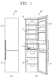
- FIG. 1 is a conceptual view of a refrigerator 100 in accordance with an embodiment of the present disclosure.
- FIG. 2 is a disassembled perspective view illustrating a structure related to the refrigerator 100 illustrated in FIG. 1 .
- the refrigerator 100 may include a refrigerator main body 10, a cold air passage duct 20, a control case 30, and a knob (shutter) 40.
- the refrigerator main body 10 may include a refrigerating chamber 11 and a freezing chamber 15.
- the refrigerator disclosed herein may be a bottom freezer type refrigerator.
- FIG. 1 illustrates the bottom freezer type refrigerator 100.
- a lower space is configured as the freezing chamber 15 and an upper space relative to the lower space is configured as the refrigerating chamber 11.
- a freezing chamber door 17 for opening and closing the freezing chamber 15 and a refrigerating chamber door 13 for opening and closing the refrigerating chamber 11 may be attached to the refrigerator main body 10.
- the present disclosure is preferably applied to the bottom freezer type refrigerator, but is not limited thereto. It is understood that the present disclosure may be applied to various types of refrigerators by adjusting an arrangement of the shutter 40, a cold air discharge opening 31, and the like, which are explained in more detail below.
- a chiller chamber drawer 18a may be attached to the lowermost end of the refrigerating chamber 11, and a chiller chamber cover 18b that forms an upper surface of a chiller chamber 18 may be attached to an upper portion of the chiller chamber drawer 18a.
- the chiller chamber drawer 18a and the chiller chamber cover 18b may be referred to as the chiller chamber 18.
- the chiller chamber 18 may store meat, and the like, and is preferably maintained at a relatively low temperature close to 0°C.
- a cold air passage duct 20 and the control case 30 may be provided at an upper portion of a rear surface of the chiller chamber drawer 18a and configured to communicate with the cold air discharge opening 31.
- the cold air passage duct 20 may be installed within the refrigerator main body 10.
- the cold air passage duct 20 may include a cold air passage 23 (see e.g., FIG. 6 ). As illustrated in FIGS. 1 and 2 , the cold air passage duct 20 may be disposed at a rear wall side of the refrigerating chamber 11 within the refrigerator main body to allow cold air to be discharged into the refrigerating chamber 11.
- Cold air generated in an evaporator may flow along the cold air passage 23 of the cold air passage duct 20.
- a refrigerating cycle is provided to supply cold air in response to a status change of a refrigerant.
- Components of the refrigerating cycle such as an evaporator, a compressor, a condenser, and an expansion valve, are components applied to a refrigerating cycle of a conventional refrigerator, so for convenience purposes a detailed description thereof is omitted.
- the control case 30 may be installed at one surface of the cold air passage duct 20.
- the control case 30 may be provided with the cold air discharge opening 31 through which cold air within the cold air passage duct 20 is discharged.
- the control case 30 may be understood as a plate structure coupled to one surface of the cold air passage duct 20. As illustrated in FIG. 2 , the control case 30 may be attached to a front surface of the cold air passage duct 20.
- a shutter accommodating portion 27 in which a shutter (knob) 40 is accommodated to be reciprocally movable may be formed in the cold air passage duct 20.
- the shutter accommodating portion 27 may be larger than the shutter 40, considering the coupling with the reciprocally-movable shutter 40.
- the shutter accommodating portion 27 may be provided with the cold air discharge opening 31 of the control case 30, which is explained below, and a cold air accommodating outlet 28 may be in communication with the cold air passage 23 disposed in the cold air passage duct 20.
- control case 30 A detailed structure of the control case 30 related to the present disclosure is described in more detail below, together with the description of the shutter 40, with reference to FIG. 5 .
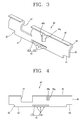
- FIG. 3 is a perspective view of the shutter 40 in accordance with an embodiment of the present disclosure.
- FIG. 4 is a front view of the shutter 40 illustrated in FIG. 3 .
- a structure of the shutter 40 will be described as illustrated in FIGS. 3 and 4 .
- the shutter 40 functions to open and/or close at least part of the cold air discharge opening 31 illustrated in FIG. 5 .
- the shutter 40 may be disposed between the cold air passage duct 20 and the control case 30.
- the shutter 40 may be installed at the control case 30 so as to be reciprocally movable in one direction.
- the shutter 40 may include a flow rate adjusting portion 41.
- the flow rate adjusting portion 41 may adjust a flow rate of cold air by adjusting a communicating area between a cut portion 47 (explained in more detail below) and the cold air discharge opening 31.
- the flow rate adjusting portion 41 may include a plurality of protrusions 41 a and a slot 41 b.
- the plurality of protrusions 41 a may be disposed at a lower end portion of the shutter 40.
- the protrusions 41 a may be spaced apart from one another by a preset distance.
- FIG. 3 illustrates one example showing three protrusions 41 a at the lower end portion of the shutter 40.
- the plurality of protrusions 41 a sequentially move over a pressing protrusion 33 (explained in more detail below). Accordingly, an opening and/or closing amount or level of the cold air discharge opening 31 may be adjusted.
- the slot 41 b which is cut off in one direction may be formed at a position adjacent to the lower end portion of the shutter 40 with the plurality of protrusions 41 a.
- the slot 41 b may enable an elastic transformation of the lower end portion of the shutter 40 in a state in which the plurality of protrusions 41 a are pressed by the pressing protrusion 33, thereby reducing a concentration of stress applied to the shutter 40 and the pressing protrusion 33 and minimizing a risk of damage.
- the slot 41 b may be understood as an elastic space in which the lower end portion of the shutter 40 with the plurality of protrusions 41 a is elastically transformed.
- FIGS. 3 and 4 illustrate one example in which the plurality of protrusions 41 a protrude from the lower end portion of the shutter 40 with predetermined intervals from one another in a lengthwise direction.
- a plurality of protrusions 41 c may be formed within a slot 41 d, which is described in more detail below with reference to FIG. 11 .
- the shutter 40 may include first, second, third, and fourth movement limit end portions 42, 43, 44 and 45, a stopping/stepping portion 46a, a cut portion 47, and a bent portion 48.
- moving directions (up, down, left, right) of the shutter 40 are defined relative to the front view of FIG. 4 .
- the first movement limit end portion 42 is provided at a lower end of the shutter 40, and brought into contact with a first protruding portion 35 (explained in more detail below) so as to limit a downward movement of the shutter 40 and guide a lateral movement of the shutter 40.
- the first movement limit end portion 42 may be formed at a position adjacent to the plurality of protrusions 41 a which downwardly protrude from the lower end portion of the shutter 40.
- the second movement limit end portion 43 is stopped by a second protruding portion 36 (explained in more detail below) so as to limit a movement of the shutter 40 in one side direction.
- the second movement limit end portion 43 may be formed in a manner of cutting off a lower end portion of one side of the shutter 40 to be connected to the first movement limit end portion 42.
- the drawing illustrates one example in which the second movement limit end portion 43 is formed by cutting off an edge portion of a left lower end of the shutter 40 and stopped by the second protruding portion 36 so as to limit a left movement of the shutter 40.
- the third movement limit end portion 44 may be formed by cutting off a lower end portion of another side of the shutter 40.
- the third movement limit end portion 44 is stopped by a third protruding portion 37 (explained in more detail below) so as to limit a downward movement of the shutter 40 and guide a lateral movement of the shutter 40.
- the drawing illustrates one example in which the third movement limit end portion 44 is formed by cutting off a right lower end portion of the shutter 40.
- the fourth movement limit end portion 45 may be connected to the third movement limit end portion 44.
- the fourth movement limit end portion 45 is stopped by a fourth protruding portion 38 to limit a movement of the shutter 40 in another side direction.
- the fourth movement limit end portion 45 may be understood as an end portion formed at a right side of the shutter 40.
- the stopping portion 46a may be formed to be bent from an upper end portion of the shutter 40 toward a shutter coupling portion 32 (see Fig. 5 ) so as to be slidably stopped in the shutter coupling portion 32.
- the stopping portion 46a may be formed to cover the shutter coupling portion 32 of the control case 30. Also, the stopping portion 46a enables the shutter 40 to be located between the control case 30 and the cold air passage duct 20.
- a shutter handle 46b may protrude from the stopping portion 46a toward a front side.
- a user may manipulate the shutter handle 46b in a generally left and right direction such that the shutter 40 can be slid. This enables the cut portion 47 of the shutter 40 to communicate with the cold air discharge opening 31, thereby adjusting the opening and closing amount of the cold air discharge opening 31.
- the shutter handle 46b may be disposed at a front side of the control case 30 to be manipulated by the user.
- FIG. 6 illustrates the structure in which the stopping portion 46a of the shutter 40 covers the control case 30 such that the shutter 40 is disposed between the control case 30 and the cold air passage duct 20.
- the cut portion 47 may be formed by cutting off at least part of an upper portion of the shutter 40 to communicate with the cold air discharge opening 31, such that at least part of one side of the cold air discharge opening 31 is open thereby to discharge the cold air.
- the cut portion 47 does not communicate with the cold air discharge opening 31 in a closed state of the cold air discharge opening 31, and at least part of the cut portion 47 may communicate with the cold air discharge opening 31 in an open state of the cold air discharge opening 31.
- a fifth movement limit end portion 49 may be formed at an upper end portion of the shutter 40.
- the fifth movement limit end portion 49 may be brought into contact with a limit rib 39 formed above the cold air discharge opening 31 to limit an upward movement of the shutter 40 and guide a lateral movement of the shutter 40.
- the fifth movement limit end portion 49 such as illustrated in FIG. 3 , may be formed at an end portion of a bent portion 48 (explained in more detail below).
- the fifth movement limit end portion 49 may be an upper end surface of the shutter 40 including a curved surface.
- the shutter 40 may include the bent portion 48 having an upper side formed in a bent shape.
- the shutter 40 may be coupled to the shutter coupling portion 32 and cover at least part of the shutter coupling portion 32.
- Such configuration may allow the shutter 40 to be more stably coupled to the control case 30. Also, with this structure, even when the shutter 40 is repetitively slid, stress which is concentrated on the shutter 40 may be dispersed, thereby improving durability.
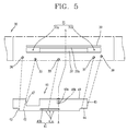
- FIG. 5 is a conceptual view illustrating a correspondence between the control case 30 and the shutter 40 according to an embodiment of the present disclosure.
- FIG. 6 is a side sectional view taken along the line A-A' of FIG. 5 .
- a structure of the control case 30 and a coupling relationship between the control case 30 and the shutter 40 will be described with reference to FIGS. 5 and 6 .
- the control case 30 may be provided with a pressing protrusion 33.
- the pressing protrusion 33 may protrude from a lower portion of the cold air discharge opening 31 toward the cold air passage duct 20.
- the pressing protrusion 33 may press the plurality of protrusions 41 a and be settled between the plurality of protrusions 41 a, thereby adjusting the opening and closing amount of the cold air discharge opening 31.
- FIG. 5 illustrates one example of the pressing protrusion 33 that protrudes from the lower portion of the cold air discharge opening 31 formed on the control case 30 with being spaced apart from the lower portion by a predetermined distance.
- the control case 30 may include first and second protruding portions 35 and 36.
- the first protruding portion 35 may protrude from a left lower side of the cold air discharge opening 31 toward the cold air passage duct 20.
- the first protruding portion 35 may be brought into contact with the first movement limit end portion 42 located at the lower end of the shutter 40 so as to limit the downward movement of the shutter 40 and guide the lateral movement of the shutter 40.
- the second protruding portion 36 may be spaced apart from the first protruding portion 35 and protrude toward the cold air passage duct 20 so as to limit the lateral movement of the shutter 40.
- the second protruding portion 36 disposed at a left side of the pressing protrusion 33 may be stopped by the second movement limit end portion 43 so as to limit the left movement of the shutter 40.
- the control case 30 may further include third and fourth protruding portions 37 and 38.
- the third protruding portion 37 may protrude from a right lower side of the cold air discharge opening 31 toward the cold air passage duct 20.
- the third protruding portion 37 may be brought into contact with the third movement limit end portion 44 so as to limit the downward movement of the shutter 40 and guide the lateral movement of the shutter 40.
- the fourth protruding portion 38 may be disposed at a right side of the third protruding portion 37 with a spaced distance to limit the lateral movement of the shutter 40, and protrude toward the cold air passage duct 20.
- the fourth protruding portion 38 may be stopped by the fourth movement limit end portion 45 so as to limit the rightward movement of the shutter 40.
- the fourth protruding portion 38 is stopped by the fourth movement limit end portion 45 so as to limit the rightward movement of the shutter 40.
- the pressing protrusion 33 may be disposed below the cold air discharge opening 31 of the control case 30 and be spaced apart from the cold air discharge opening 31, the first and second protruding portions 35 and 36 may be sequentially disposed at the left side of the pressing protrusion 33, and the third and fourth protruding portions 37 and 38 may be sequentially disposed at the right side of the pressing protrusion 33.
- the control case 30 may further include the shutter coupling portion 32.
- the shutter coupling portion 32 may be formed between both sides of the cold air discharge opening 31 and be spaced apart from an upper portion of the cold air discharge opening 31 by a predetermined distance, so that a longitudinal slot 32a is obtained through which the stopping portion 46a runs and matures into the shutter handle 46b (see Figs. 5 and 6 )
- the cold air discharge opening 31 may be formed at each of both sides of the shutter coupling portion 32.
- the cold air discharge opening 31 formed at the left side of the control case 30 of FIG. 5 may be referred to as a first cold air discharge opening 31 a
- the cold air discharge opening 31 formed at the right side of the control case 30 may be referred to as a second cold air discharge opening 31 b.
- the first cold air discharge opening 31 a may communicate with the cut portion 47 of the shutter 40 so as to be open.
- the fourth movement limit end portion 45 may open the second cold air discharge opening 31 b.
- the first and second cold air discharge openings 31 a and 31 b may be opening and closing at the same time in response to the reciprocal movement of the shutter 40.
- the first and second cold air discharge openings 31 a and 31 b may be opened in a manner of always having the same area. More specifically, a width of the first cold air discharge opening 31 a in a left and right direction may be the same as a width of the cut portion 47 in the left and right direction. Also, a distance from one end of a right side of the cut portion 47 to the fourth movement limit end portion 45 may be the same as a distance in the left and right direction of the shutter coupling portion 32 disposed between the first and second cold air discharge openings 31 a and 31 b.
- the cold air discharge opening 31 may be formed by dividing both sides thereof into the first and second cold air discharge openings 31 a and 31 b.
- the first and second cold air discharge openings 31 a and 31 b may always have the same area in the open state of the shutter 40.
- Such structure may prevent more cold air from being supplied through one side of the cold air discharge opening 31, and allow the cold air to be uniformly supplied into the refrigerating chamber 11.
- a limit rib 39 to limit the upward movement of the shutter 40 may protrude above the cold air discharge opening 31.
- the limit rib 39 may be brought into contact with the fifth movement limit end portion 49 located at the upper side of the shutter 40, to limit the upward movement of the shutter 40 and guide the lateral movement of the shutter 40.
- FIG. 7 is a conceptual view illustrating a closed state of the cold air discharge opening 31 by the shutter 40 in accordance with an embodiment of the present disclosure.
- FIG. 8 is a conceptual view illustrating a coupling relationship between the shutter 40 and the control case 30 in the state of FIG. 7 .
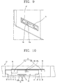
- FIG. 9 is a conceptual view illustrating an open state of the cold air discharge opening 31 by the shutter 40 according to the present disclosure.
- FIG. 10 is a conceptual view illustrating a coupling relationship between the shutter 40 and the control case 30 in the state of FIG. 9 .
- operations of the shutter 40 installed on the control case 30 related to the refrigerator 100 according to an embodiment of the present disclosure will be described with reference to FIGS. 5 , 7 , 8 , 9, and 10 .
- FIGS. 7 and 8 illustrate a state in which the shutter 40 is moved in an arrow direction and closes the first and second cold air discharge openings 31 a and 31 b.
- the fourth movement limit end portion 45 may be brought into contact with the fourth protruding portion 38
- the first and third movement limit end portions 42 and 44 may be brought into contact with the first and third protruding portions 35 and 37, respectively, so as to limit the downward movement of the shutter 40 and guide the lateral movement of the shutter 40.
- the second protruding portion 36 may be spaced apart from the second movement limit end portion 43.
- the first cold air discharge opening 31 a may be closed by a portion of the shutter 40 located near the left side of the cut portion 47 of the shutter 40, and the second cold air discharge opening 31 b may be closed by a portion of the shutter 40 located near the fourth movement limit end portion 45.
- FIGS. 9 and 10 illustrate a state in which the shutter 40 is moved in an arrow direction and opens the first and second cold air discharge openings 31 a and 31 b.
- the second movement limit end portion 43 may be brought into contact with the left second protruding portion 36, and the first and third movement limit end portions 42 and 44 may be brought into contact with the first and third protruding portions 35 and 37, to limit the downward movement of the shutter 40 and guide the lateral movement of the shutter 40.
- the fourth protruding portion 38 may be spaced apart from the fourth movement limit end portion 45.
- both of the first cold air discharge opening 31 a and the second cold air discharge opening 31 b are open.
- FIGS. 7, 8 , 9, and 10 illustrate examples in which the cold air discharge opening 31 is fully closed and fully opened.
- the shutter 40 may be manipulated to open only a part of the cold air discharge opening 31. Even when the cold air discharge opening is only partially opened, the first cold air discharge opening 31 a and the second cold air discharge opening 31 b have the same area.
- One of the plurality of protrusions 41 a may be pressed by the pressing protrusion 33 and another one of the plurality of protrusions 41 a may move over the pressing protrusion 33.
- the one protrusion of the plurality of protrusions 41 a is pressed by the pressing protrusion 33, the lower end portion of the shutter 40 is elastically transformed upwardly.
- the cold air discharge opening 31 is adjusted to be open by a predetermined area.
- FIG. 11 is a front view of the shutter 40 in accordance with another embodiment of the present disclosure.
- the shutter 40 of FIG. 11 is configured to open and close at least part of the cold air discharge opening 31.
- the shutter 40 may be disposed between the cold air passage duct 20 and the control case 30, and installed on the control case 30 to be reciprocally movable in one direction.
- the shutter 40 may include the flow rate adjusting portion 41.
- the flow rate adjusting portion 41 can adjust the flow rate of cold air by adjusting a communicating area between the cut portion 47 and the cold air discharge opening 31.
- the flow rate adjusting portion 41 may include a plurality of protrusions 41 c and a slot 41 d.
- the shutter according to the embodiment illustrated in FIG. 11 is different than the shutter according to the embodiment illustrated in FIG. 5 regarding the plurality of protrusions 41 c and the slot 41 d.
- the plurality of protrusions 41 a are disposed at the lower end portion of the shutter 40 with being spaced apart from one another by the preset intervals, the plurality of protrusions 41 c according to the shutter of FIG. 11 upwardly protrude from a lower side within the slot 41 d.
- the slot 41 d which is cut in one direction is formed at a position adjacent to a lower end of the shutter 40. Also, FIG. 11 illustrates that the protrusions 41 c of the shutter 40 upwardly protrude from the lower side within the slot 41 d.
- the pressing protrusion 33 of the control case 30 may be disposed to be inserted into the slot 41 d so as to press the plurality of protrusions 41 c.
- the plurality of protrusions 41 c are pressed by the pressing protrusion which is inserted into the slot 41 d, the lower end portion of the shutter 40 is elastically transformed downwardly.
- the slot 41 d may be understood as an elastic space in which the lower end of the shutter 40 is elastically transformed.
- the plurality of protrusions 41 c may be sequentially moved over the pressing protrusion 33 while the shutter 40 moves in one direction, and the pressing protrusion 33 may be disposed between the protrusions 41 c. Accordingly, an opening and closing amount of the cold air discharge opening 31 is adjusted.
- the slot 41 d may allow for the elastic transformation of the lower end portion of the shutter 40 in the state in which the plurality of protrusions 41 c are pressed by the pressing protrusion 33, thereby reducing a concentration of stress applied to the shutter 40 and the pressing protrusion 33 and minimizing a risk of damage.
- the pressing protrusion may be provided on the control case and the flow rate adjusting portion pressed by the pressing protrusion may be provided on the shutter, which may allow for adjusting an opening and closing amount of the cold air discharge opening in a manual manner.
- the shutter coupling portion may be formed on the cold air discharge opening and the stopping portion may be slidably coupled to the shutter coupling portion, thereby enabling a manual manipulation of the shutter. This may result in reducing power consumption and material costs and implementing user-desired temperature.
- both sides of the cold air discharge opening which are adjacent to the shutter coupling portion may always have the same area in an open state of the shutter, thereby uniformly supplying cold air into a refrigerating chamber through the both sides of the cold air discharge opening.
Abstract
Description
- A refrigerator having a structure capable of adjusting a flow rate of cold air supplied into a refrigerator main body by a user's manual operation.
- In general, a refrigerator keeps foods such as meat, fish, vegetables, fruits, beverages and the like in a fresh state. A conventional refrigerator includes a refrigerator main body having storage spaces such as a freezing chamber, a refrigerating chamber, vegetable chambers, and the like, a refrigerating cycle device provided in the refrigerator main body, and a door mounted to one side of the refrigerator main body to open and close the storage spaces.
- The refrigerating cycle device of the refrigerator is activated when temperature of the freezing chamber or the refrigerating chamber is more than a preset temperature. In response to the activation of the refrigerating cycle device, cold air is generated in an evaporator and then circulates along the storage spaces. While the cold air circulates along the storage spaces, the storage spaces are maintained at preset temperatures.
- Refrigerators are classified into various types according to a method of circulating cold air, locations of a freezing chamber, and a refrigerating chamber, and a configuration of an evaporator.
- As one example, refrigerators may include a refrigerator having a freezing chamber located above a refrigerating chamber, a refrigerator having a freezing chamber and a refrigerating chamber located side by side, a refrigerator having a freezing chamber located below a refrigerating chamber, and the like.
- A chiller chamber may be formed at the lowermost portion of the refrigerating chamber. The chiller chamber may include a chiller chamber drawer, and a chiller chamber cover forming an upper surface of the chiller chamber drawer. The chiller chamber may be used to store meat and the like. The chiller chamber is preferably maintained at a relatively low temperature close to 0°C. To this end, a duct with a cold air passage is installed at a rear side of the chiller chamber so as to supply cold air into the chiller chamber. The amount of cold air should be adjusted according to an amount of meat kept in the chiller chamber or an external temperature.
- A conventional refrigerator includes a damper or an insulating material installed in the duct, along which the cold air flows, to adjust the amount of cold air supplied into the refrigerating chamber. However, the damper or the insulating material are not manually controlled by a user, but automatically controlled in an electric manner. Moreover, the amount of cold air was controlled by electrically adjusting an opening and closing amount of the damper, which made it impossible to adjust the amount of cold air supplied into the refrigerating chamber according to a user's need. Additionally, cold air supplied to the refrigerating chamber along the duct was not uniformly supplied through a cold air discharge opening.
- Furthermore, the electric control of the amount of cold air resulted in increased power consumption, as well as increased material costs due to the installation of the damper and electric components for controlling the damper.
- The present disclosure is directed to providing a structure for adjusting a flow rate of cold air supplied into a refrigerating chamber according to a user's request in a manner of installing a shutter (knop), which is manually manipulated by a user.
- Additionally, the present disclosure is directed to providing a cold air flow rate adjustment structure, capable of reducing power consumption and material costs and implementing a user-desired temperature.
- Additionally, the present disclosure is directed to providing a structure capable of uniformly supplying cold air through a cold air discharge opening while supplying the cold air into a refrigerating chamber through the cold air discharge opening.
- To achieve these and other advantages and in accordance with the purpose of this specification, as embodied and broadly described herein, there is provided a refrigerator including a main body having a refrigerating chamber therein, a cold air passage duct disposed within the main body, the cold air passage duct including a cold air passage to discharge cold air into the refrigerating chamber, a control case attached to one surface of the cold air discharge duct, the control case including a cold air discharge opening through which the cold air is discharged, a shutter provided between the cold air passage duct and the control case, the shutter being reciprocally movable in one direction to open and close at least part of the cold air discharge opening, wherein the control case includes a pressing protrusion to press against a lower end portion of the shutter, the pressing protrusion provided below the cold air discharge opening and protruding toward the cold air passage duct, wherein the shutter includes a flow rate adjusting portion to adjust an opening and closing amount of the cold air discharge opening in response to being pressed by the pressing protrusion, and wherein the flow rate adjusting portion includes a plurality of protrusions disposed at the lower end portion of the shutter that are spaced apart from one another by a preset distance, and a slot cut off to enable an elastic transformation of the lower end portion of the shutter when the protrusions are pressed by the pressing protrusion.
- According to an aspect of the present disclosure, the control case includes a first protruding portion provided below a first side of the cold air discharge opening and protruding toward the cold air passage duct, whereby the first protruding portion contacts the lower end of the shutter to limit a downward movement of the shutter and guide a lateral movement of the shutter, and a second protruding portion provided at one side of the pressing protrusion and protruding toward the cold air passage duct to limit the lateral movement of the shutter, the second protruding portion being positioned such that the first protruding portion is disposed between the pressing protrusion and the second protruding portion.
- According to an aspect of the present disclosure, the shutter includes a first movement limit end portion provided at the lower end portion of the shutter, whereby the first movement end portion contacts the first protruding portion to limit the downward movement of the shutter and guide the lateral movement of the shutter, and a second movement limit end portion formed at a lower end portion of a first side of the shutter, whereby the second movement end portion is connected to the first movement limit end portion and contacts the second protruding portion to limit a movement of the shutter in a first side direction.
- According to an aspect of the present disclosure, the control case further includes a third protruding portion provided below a second side of the cold air discharge opening and protruding toward the cold air passage duct, whereby the third protruding portion contacts at least part of the shutter to limit the downward movement of the shutter and guide the lateral movement of the shutter, and a fourth protruding portion protruding toward the cold air passage duct to limit the lateral movement of the shutter, the fourth protruding portion being positioned such that the third protruding portion is disposed between the pressing protrusion and the fourth protruding portion.
- According to an aspect of the present disclosure, the shutter further includes a third movement limit end portion formed by cutting off a lower end portion of a second side of the shutter, whereby the third movement limit end portion contacts the third protruding portion to limit the downward movement of the shutter and guide the lateral movement of the shutter, a fourth movement limit end portion provided at the second side of the shutter, whereby the fourth movement limit end portion is connected to the third movement limit end portion and contacts the fourth protruding portion to limit a movement of the shutter in a second side direction.
- A chiller chamber may be provided at the lowermost portion of the refrigerating chamber, the control case having the cold air discharge opening may be provided adjacent to the chiller chamber, and the cold air discharge opening may be communicably coupled with an inlet of the chiller chamber to supply the cold air into the chiller chamber.
- The control case may further comprise a shutter coupling portion formed between a first side and a second side of the cold air discharge opening, the shutter coupling portion being spaced apart from an upper portion of the cold air discharge opening by a predetermined distance, whereby the shutter may be slidably coupled to the control case.
- The shutter may further comprise a stopping portion, the stepping portion being an upper end portion of the shutter that is bent toward the shutter coupling portion, whereby the shutter may be slidably coupled to the shutter coupling portion.
- The shutter may further comprise a cut portion, the cut portion being formed by cutting off at least part of an upper portion of the shutter, whereby the cut portion is communicably coupled with the cold air discharge opening such that the cold air is discharged by opening at least part of one of the first side or the second side of the cold air discharge opening, wherein the cold air discharge opening is disposed at each of both sides of the shutter coupling portion, and both the first and second sides of the cold air discharge opening are configured to discharge the cold air therethrough such that one of the first and second cold air discharge openings is open while the other of the first and second cold air discharge openings is open in response to at least part of the other of the first and second cold air discharge opening communicating with the cut portion.
- The first and second cold air discharge openings may have the same area in a state of being opened and closed by the shutter thereby allowing cold air to be uniformly supplied into the refrigerating chamber through the first and second cold air discharge openings.
- The plurality of protrusions may protrude upward from a lower side within the slot to elastically transform the lower end portion of the shutter in a downward direction in a state in which one of the plurality of protrusions is pressed by the pressing protrusion.
- The plurality of protrusions may protrude downward from the lower end portion of the shutter to elastically transform the lower end portion of the shutter in an upward direction in a state in which one of the plurality of protrusions is pressed by the pressing protrusion.
- The first protruding portion may be provided directly below the first side of the cold discharge air opening, and the third protruding portion is provided directly below the second side of the cold air discharge opening.
- An opening and closing degree of the cold air discharge opening ma correlate to the number of protrusions disposed at the lower end portion of the shutter and distance between the protrusions.
- Further scope of applicability of the present application will become more apparent from the detailed description given hereinafter. However, it should be understood that the detailed description and specific examples, while indicating preferred embodiments of the invention, are given by way of illustration only, since various changes and modifications within the scope of the invention will become apparent to those skilled in the art from the detailed description.
- The accompanying drawings, which are included to provide a further understanding of the invention and are incorporated in and constitute a part of this specification, illustrate exemplary embodiments and together with the description serve to explain the principles of the invention. In the drawings:
-
FIG. 1 is a conceptual view of a refrigerator in accordance with the present disclosure; -
FIG. 2 is a disassembled perspective view illustrating the structure related to the refrigerator illustrated inFIG. 1 ; -
FIG. 3 is a perspective view of a shutter in accordance with one embodiment of the present disclosure; -
FIG. 4 is a front view of the shutter illustrated inFIG. 3 ; -
FIG. 5 is a conceptual view illustrating relationship between a control case and the shutter; -
FIG. 6 is a side sectional view taken along the line A-A' ofFIG. 5 ; -
FIG. 7 is a conceptual view illustrating a closed state of a cold air discharge opening by the shutter in accordance with the present disclosure; -
FIG. 8 is a conceptual view illustrating a coupling relationship between the shutter and the control case in the state ofFIG. 7 ; -
FIG. 9 is a conceptual view illustrating an open state of the cold air discharge opening by the shutter according to the present disclosure; -
FIG. 10 is a conceptual view illustrating a coupling relationship between the shutter and the control case in the state ofFIG. 9 ; and -
FIG. 11 is a front view of a shutter in accordance with another embodiment of the present disclosure. - Hereinafter, exemplary embodiments of the present disclosure invention will be described in detail with reference to the accompanying drawings. It is understood that the description herein is not intended to limit the claims to the specific embodiments described. On the contrary, it is intended to cover alternatives, modifications, and equivalents as may be included within the spirit and scope of the present disclosure.
- It is understood that although the terms first, second, etc. may be used herein to describe various elements, these elements should not be limited by these terms. These terms are generally only used to distinguish one element from another. Further, it is understood that when an element is referred to as being "connected with" another element, the element can be connected with the other element or intervening elements may also be present. In contrast, when an element is referred to as being "directly connected with" another element, there are no intervening elements present. Further, it is understood that a singular representation may include a plural representation unless it represents a definitely different meaning from the context. Further, it is understood that terms such as "include" or "has" are used herein and should be understood that they are intended to indicate an existence of features, numbers, steps, functions, several components, or combinations thereof, disclosed in the specification, and it is also understood that greater or fewer features, numbers, steps, functions, several components, or combinations thereof may likewise be utilized.
-
FIG. 1 is a conceptual view of arefrigerator 100 in accordance with an embodiment of the present disclosure.FIG. 2 is a disassembled perspective view illustrating a structure related to therefrigerator 100 illustrated inFIG. 1 . - As illustrated in
FIGS. 1 and2 , therefrigerator 100 may include a refrigeratormain body 10, a coldair passage duct 20, acontrol case 30, and a knob (shutter) 40. The refrigeratormain body 10 may include a refrigeratingchamber 11 and a freezingchamber 15. For example, the refrigerator disclosed herein may be a bottom freezer type refrigerator. -
FIG. 1 illustrates the bottomfreezer type refrigerator 100. In the bottomfreezer type refrigerator 100, a lower space is configured as the freezingchamber 15 and an upper space relative to the lower space is configured as the refrigeratingchamber 11. A freezingchamber door 17 for opening and closing the freezingchamber 15 and a refrigeratingchamber door 13 for opening and closing the refrigeratingchamber 11 may be attached to the refrigeratormain body 10. - The present disclosure is preferably applied to the bottom freezer type refrigerator, but is not limited thereto. It is understood that the present disclosure may be applied to various types of refrigerators by adjusting an arrangement of the
shutter 40, a coldair discharge opening 31, and the like, which are explained in more detail below. - Specifically, in the structure disclosed herein, a
chiller chamber drawer 18a may be attached to the lowermost end of the refrigeratingchamber 11, and achiller chamber cover 18b that forms an upper surface of achiller chamber 18 may be attached to an upper portion of thechiller chamber drawer 18a. Together, thechiller chamber drawer 18a and thechiller chamber cover 18b may be referred to as thechiller chamber 18. Thechiller chamber 18 may store meat, and the like, and is preferably maintained at a relatively low temperature close to 0°C. - An introduction of cold air into the
chiller chamber drawer 18a disposed at the lowermost end of the refrigeratingchamber 11 should be allowed. A coldair passage duct 20 and thecontrol case 30 may be provided at an upper portion of a rear surface of thechiller chamber drawer 18a and configured to communicate with the coldair discharge opening 31. - The cold
air passage duct 20 may be installed within the refrigeratormain body 10. The coldair passage duct 20 may include a cold air passage 23 (see e.g.,FIG. 6 ). As illustrated inFIGS. 1 and2 , the coldair passage duct 20 may be disposed at a rear wall side of the refrigeratingchamber 11 within the refrigerator main body to allow cold air to be discharged into the refrigeratingchamber 11. - Cold air generated in an evaporator may flow along the
cold air passage 23 of the coldair passage duct 20. In the coldair passage duct 20 of the present disclosure, similar to a conventional refrigerator, a refrigerating cycle is provided to supply cold air in response to a status change of a refrigerant. Components of the refrigerating cycle, such as an evaporator, a compressor, a condenser, and an expansion valve, are components applied to a refrigerating cycle of a conventional refrigerator, so for convenience purposes a detailed description thereof is omitted. - The
control case 30 may be installed at one surface of the coldair passage duct 20. Thecontrol case 30 may be provided with the coldair discharge opening 31 through which cold air within the coldair passage duct 20 is discharged. Thecontrol case 30 may be understood as a plate structure coupled to one surface of the coldair passage duct 20. As illustrated inFIG. 2 , thecontrol case 30 may be attached to a front surface of the coldair passage duct 20. - A
shutter accommodating portion 27 in which a shutter (knob) 40 is accommodated to be reciprocally movable may be formed in the coldair passage duct 20. Theshutter accommodating portion 27 may be larger than theshutter 40, considering the coupling with the reciprocally-movable shutter 40. Theshutter accommodating portion 27 may be provided with the cold air discharge opening 31 of thecontrol case 30, which is explained below, and a coldair accommodating outlet 28 may be in communication with thecold air passage 23 disposed in the coldair passage duct 20. - A detailed structure of the
control case 30 related to the present disclosure is described in more detail below, together with the description of theshutter 40, with reference toFIG. 5 . -
FIG. 3 is a perspective view of theshutter 40 in accordance with an embodiment of the present disclosure.FIG. 4 is a front view of theshutter 40 illustrated inFIG. 3 . Hereinafter, a structure of theshutter 40 will be described as illustrated inFIGS. 3 and 4 . - The
shutter 40 functions to open and/or close at least part of the coldair discharge opening 31 illustrated inFIG. 5 . Theshutter 40 may be disposed between the coldair passage duct 20 and thecontrol case 30. Theshutter 40 may be installed at thecontrol case 30 so as to be reciprocally movable in one direction. - The
shutter 40 may include a flowrate adjusting portion 41. The flowrate adjusting portion 41 may adjust a flow rate of cold air by adjusting a communicating area between a cut portion 47 (explained in more detail below) and the coldair discharge opening 31. The flowrate adjusting portion 41 may include a plurality ofprotrusions 41 a and aslot 41 b. - The plurality of
protrusions 41 a may be disposed at a lower end portion of theshutter 40. Theprotrusions 41 a may be spaced apart from one another by a preset distance.FIG. 3 illustrates one example showing threeprotrusions 41 a at the lower end portion of theshutter 40. During a movement of theshutter 40 in one direction, the plurality ofprotrusions 41 a sequentially move over a pressing protrusion 33 (explained in more detail below). Accordingly, an opening and/or closing amount or level of the coldair discharge opening 31 may be adjusted. - The
slot 41 b which is cut off in one direction may be formed at a position adjacent to the lower end portion of theshutter 40 with the plurality ofprotrusions 41 a. Theslot 41 b may enable an elastic transformation of the lower end portion of theshutter 40 in a state in which the plurality ofprotrusions 41 a are pressed by the pressingprotrusion 33, thereby reducing a concentration of stress applied to theshutter 40 and thepressing protrusion 33 and minimizing a risk of damage. Theslot 41 b may be understood as an elastic space in which the lower end portion of theshutter 40 with the plurality ofprotrusions 41 a is elastically transformed. -
FIGS. 3 and 4 illustrate one example in which the plurality ofprotrusions 41 a protrude from the lower end portion of theshutter 40 with predetermined intervals from one another in a lengthwise direction. However, a plurality ofprotrusions 41 c may be formed within aslot 41 d, which is described in more detail below with reference toFIG. 11 . - The
shutter 40 may include first, second, third, and fourth movement limitend portions portion 46a, acut portion 47, and abent portion 48. Hereinafter, moving directions (up, down, left, right) of theshutter 40 are defined relative to the front view ofFIG. 4 . - The first movement
limit end portion 42 is provided at a lower end of theshutter 40, and brought into contact with a first protruding portion 35 (explained in more detail below) so as to limit a downward movement of theshutter 40 and guide a lateral movement of theshutter 40. For example, the first movementlimit end portion 42 may be formed at a position adjacent to the plurality ofprotrusions 41 a which downwardly protrude from the lower end portion of theshutter 40. - The second movement
limit end portion 43 is stopped by a second protruding portion 36 (explained in more detail below) so as to limit a movement of theshutter 40 in one side direction. The second movementlimit end portion 43 may be formed in a manner of cutting off a lower end portion of one side of theshutter 40 to be connected to the first movementlimit end portion 42. The drawing illustrates one example in which the second movementlimit end portion 43 is formed by cutting off an edge portion of a left lower end of theshutter 40 and stopped by the second protrudingportion 36 so as to limit a left movement of theshutter 40. - The third movement
limit end portion 44 may be formed by cutting off a lower end portion of another side of theshutter 40. The third movementlimit end portion 44 is stopped by a third protruding portion 37 (explained in more detail below) so as to limit a downward movement of theshutter 40 and guide a lateral movement of theshutter 40. The drawing illustrates one example in which the third movementlimit end portion 44 is formed by cutting off a right lower end portion of theshutter 40. - The fourth movement
limit end portion 45 may be connected to the third movementlimit end portion 44. The fourth movementlimit end portion 45 is stopped by a fourth protrudingportion 38 to limit a movement of theshutter 40 in another side direction. Referring to the drawing, the fourth movementlimit end portion 45 may be understood as an end portion formed at a right side of theshutter 40. - The stopping
portion 46a may be formed to be bent from an upper end portion of theshutter 40 toward a shutter coupling portion 32 (seeFig. 5 ) so as to be slidably stopped in theshutter coupling portion 32. The stoppingportion 46a may be formed to cover theshutter coupling portion 32 of thecontrol case 30. Also, the stoppingportion 46a enables theshutter 40 to be located between thecontrol case 30 and the coldair passage duct 20. - A
shutter handle 46b may protrude from the stoppingportion 46a toward a front side. A user may manipulate theshutter handle 46b in a generally left and right direction such that theshutter 40 can be slid. This enables thecut portion 47 of theshutter 40 to communicate with the coldair discharge opening 31, thereby adjusting the opening and closing amount of the coldair discharge opening 31. - The
shutter handle 46b may be disposed at a front side of thecontrol case 30 to be manipulated by the user. -
FIG. 6 illustrates the structure in which the stoppingportion 46a of theshutter 40 covers thecontrol case 30 such that theshutter 40 is disposed between thecontrol case 30 and the coldair passage duct 20. - The
cut portion 47 may be formed by cutting off at least part of an upper portion of theshutter 40 to communicate with the coldair discharge opening 31, such that at least part of one side of the coldair discharge opening 31 is open thereby to discharge the cold air. Thecut portion 47 does not communicate with the coldair discharge opening 31 in a closed state of the coldair discharge opening 31, and at least part of thecut portion 47 may communicate with the coldair discharge opening 31 in an open state of the coldair discharge opening 31. - A fifth movement
limit end portion 49 may be formed at an upper end portion of theshutter 40. The fifth movementlimit end portion 49 may be brought into contact with alimit rib 39 formed above the coldair discharge opening 31 to limit an upward movement of theshutter 40 and guide a lateral movement of theshutter 40. The fifth movementlimit end portion 49, such as illustrated inFIG. 3 , may be formed at an end portion of a bent portion 48 (explained in more detail below). In this instance, the fifth movementlimit end portion 49 may be an upper end surface of theshutter 40 including a curved surface. - Referring to
FIGS. 3 and6 , theshutter 40 may include thebent portion 48 having an upper side formed in a bent shape. Referring toFIG. 6 , theshutter 40 may be coupled to theshutter coupling portion 32 and cover at least part of theshutter coupling portion 32. Such configuration may allow theshutter 40 to be more stably coupled to thecontrol case 30. Also, with this structure, even when theshutter 40 is repetitively slid, stress which is concentrated on theshutter 40 may be dispersed, thereby improving durability. -
FIG. 5 is a conceptual view illustrating a correspondence between thecontrol case 30 and theshutter 40 according to an embodiment of the present disclosure.FIG. 6 is a side sectional view taken along the line A-A' ofFIG. 5 . Hereinafter, a structure of thecontrol case 30 and a coupling relationship between thecontrol case 30 and theshutter 40 will be described with reference toFIGS. 5 and6 . - The
control case 30 may be provided with apressing protrusion 33. Thepressing protrusion 33 may protrude from a lower portion of the coldair discharge opening 31 toward the coldair passage duct 20. Thepressing protrusion 33 may press the plurality ofprotrusions 41 a and be settled between the plurality ofprotrusions 41 a, thereby adjusting the opening and closing amount of the coldair discharge opening 31.FIG. 5 illustrates one example of thepressing protrusion 33 that protrudes from the lower portion of the coldair discharge opening 31 formed on thecontrol case 30 with being spaced apart from the lower portion by a predetermined distance. - The
control case 30 may include first and second protrudingportions - The first protruding
portion 35 may protrude from a left lower side of the coldair discharge opening 31 toward the coldair passage duct 20. The first protrudingportion 35 may be brought into contact with the first movementlimit end portion 42 located at the lower end of theshutter 40 so as to limit the downward movement of theshutter 40 and guide the lateral movement of theshutter 40. - The second protruding
portion 36 may be spaced apart from the first protrudingportion 35 and protrude toward the coldair passage duct 20 so as to limit the lateral movement of theshutter 40. For example, regarding the embodiment illustrated inFIG. 5 , the second protrudingportion 36 disposed at a left side of thepressing protrusion 33 may be stopped by the second movementlimit end portion 43 so as to limit the left movement of theshutter 40. - The
control case 30 may further include third and fourth protrudingportions - The third protruding
portion 37 may protrude from a right lower side of the coldair discharge opening 31 toward the coldair passage duct 20. The third protrudingportion 37 may be brought into contact with the third movementlimit end portion 44 so as to limit the downward movement of theshutter 40 and guide the lateral movement of theshutter 40. - The fourth protruding
portion 38 may be disposed at a right side of the third protrudingportion 37 with a spaced distance to limit the lateral movement of theshutter 40, and protrude toward the coldair passage duct 20. The fourth protrudingportion 38 may be stopped by the fourth movementlimit end portion 45 so as to limit the rightward movement of theshutter 40. For example, regarding the embodiment illustrated inFIG. 4 , the fourth protrudingportion 38 is stopped by the fourth movementlimit end portion 45 so as to limit the rightward movement of theshutter 40. - Referring to
FIG. 5 , the pressingprotrusion 33 may be disposed below the cold air discharge opening 31 of thecontrol case 30 and be spaced apart from the coldair discharge opening 31, the first and second protrudingportions pressing protrusion 33, and the third and fourth protrudingportions pressing protrusion 33. - The
control case 30 may further include theshutter coupling portion 32. Theshutter coupling portion 32 may be formed between both sides of the coldair discharge opening 31 and be spaced apart from an upper portion of the coldair discharge opening 31 by a predetermined distance, so that alongitudinal slot 32a is obtained through which the stoppingportion 46a runs and matures into theshutter handle 46b (seeFigs. 5 and6 ) The coldair discharge opening 31 may be formed at each of both sides of theshutter coupling portion 32. The coldair discharge opening 31 formed at the left side of thecontrol case 30 ofFIG. 5 may be referred to as a first cold air discharge opening 31 a, and the coldair discharge opening 31 formed at the right side of thecontrol case 30 may be referred to as a second coldair discharge opening 31 b. - Regarding the first and second cold
air discharge openings shutter 40 is attached to theshutter coupling portion 32 so as to be reciprocally movable, the first cold air discharge opening 31 a may communicate with thecut portion 47 of theshutter 40 so as to be open. In this instance, the fourth movementlimit end portion 45 may open the second coldair discharge opening 31 b. As such, the first and second coldair discharge openings shutter 40. - The first and second cold
air discharge openings cut portion 47 in the left and right direction. Also, a distance from one end of a right side of thecut portion 47 to the fourth movementlimit end portion 45 may be the same as a distance in the left and right direction of theshutter coupling portion 32 disposed between the first and second coldair discharge openings - The cold
air discharge opening 31 may be formed by dividing both sides thereof into the first and second coldair discharge openings air discharge openings shutter 40. Such structure may prevent more cold air from being supplied through one side of the coldair discharge opening 31, and allow the cold air to be uniformly supplied into the refrigeratingchamber 11. - A
limit rib 39 to limit the upward movement of theshutter 40 may protrude above the coldair discharge opening 31. Thelimit rib 39 may be brought into contact with the fifth movementlimit end portion 49 located at the upper side of theshutter 40, to limit the upward movement of theshutter 40 and guide the lateral movement of theshutter 40. -
FIG. 7 is a conceptual view illustrating a closed state of the coldair discharge opening 31 by theshutter 40 in accordance with an embodiment of the present disclosure.FIG. 8 is a conceptual view illustrating a coupling relationship between theshutter 40 and thecontrol case 30 in the state ofFIG. 7 .FIG. 9 is a conceptual view illustrating an open state of the coldair discharge opening 31 by theshutter 40 according to the present disclosure.FIG. 10 is a conceptual view illustrating a coupling relationship between theshutter 40 and thecontrol case 30 in the state ofFIG. 9 . Hereinafter, operations of theshutter 40 installed on thecontrol case 30 related to therefrigerator 100 according to an embodiment of the present disclosure will be described with reference toFIGS. 5 ,7 ,8 ,9, and 10 . -
FIGS. 7 and 8 illustrate a state in which theshutter 40 is moved in an arrow direction and closes the first and second coldair discharge openings limit end portion 45 may be brought into contact with the fourth protrudingportion 38, and the first and third movement limitend portions portions shutter 40 and guide the lateral movement of theshutter 40. The second protrudingportion 36 may be spaced apart from the second movementlimit end portion 43. - The first cold air discharge opening 31 a may be closed by a portion of the
shutter 40 located near the left side of thecut portion 47 of theshutter 40, and the second coldair discharge opening 31 b may be closed by a portion of theshutter 40 located near the fourth movementlimit end portion 45. -
FIGS. 9 and 10 illustrate a state in which theshutter 40 is moved in an arrow direction and opens the first and second coldair discharge openings limit end portion 43 may be brought into contact with the left second protrudingportion 36, and the first and third movement limitend portions portions shutter 40 and guide the lateral movement of theshutter 40. The fourth protrudingportion 38 may be spaced apart from the fourth movementlimit end portion 45. - As the
shutter 40 is moved in a manner that thecut portion 47 communicates with the first cold air discharge opening 31 a and the fourth movementlimit end portion 45 is disposed at the left side of the second coldair discharge opening 31 b, both of the first cold air discharge opening 31 a and the second coldair discharge opening 31 b are open. -
FIGS. 7, 8 ,9, and 10 illustrate examples in which the coldair discharge opening 31 is fully closed and fully opened. However, it is understood that theshutter 40 may be manipulated to open only a part of the coldair discharge opening 31. Even when the cold air discharge opening is only partially opened, the first cold air discharge opening 31 a and the second coldair discharge opening 31 b have the same area. - One of the plurality of
protrusions 41 a may be pressed by the pressingprotrusion 33 and another one of the plurality ofprotrusions 41 a may move over thepressing protrusion 33. Thus, when the one protrusion of the plurality ofprotrusions 41 a is pressed by the pressingprotrusion 33, the lower end portion of theshutter 40 is elastically transformed upwardly. - In a state in which the
pressing protrusion 33 is disposed between the neighboring protrusions of the plurality ofprotrusions 41 a, the coldair discharge opening 31 is adjusted to be open by a predetermined area. -
FIG. 11 is a front view of theshutter 40 in accordance with another embodiment of the present disclosure. - As discussed with respect to the shutter illustrated in
FIG. 5 , theshutter 40 ofFIG. 11 is configured to open and close at least part of the coldair discharge opening 31. Theshutter 40 may be disposed between the coldair passage duct 20 and thecontrol case 30, and installed on thecontrol case 30 to be reciprocally movable in one direction. - The
shutter 40 may include the flowrate adjusting portion 41. The flowrate adjusting portion 41 can adjust the flow rate of cold air by adjusting a communicating area between thecut portion 47 and the coldair discharge opening 31. The flowrate adjusting portion 41 may include a plurality ofprotrusions 41 c and aslot 41 d. - The shutter according to the embodiment illustrated in
FIG. 11 is different than the shutter according to the embodiment illustrated inFIG. 5 regarding the plurality ofprotrusions 41 c and theslot 41 d. Unlike the shutter ofFIG. 5 , in which the plurality ofprotrusions 41 a are disposed at the lower end portion of theshutter 40 with being spaced apart from one another by the preset intervals, the plurality ofprotrusions 41 c according to the shutter ofFIG. 11 upwardly protrude from a lower side within theslot 41 d. - The
slot 41 d which is cut in one direction is formed at a position adjacent to a lower end of theshutter 40. Also,FIG. 11 illustrates that theprotrusions 41 c of theshutter 40 upwardly protrude from the lower side within theslot 41 d. - Although not illustrated, the pressing
protrusion 33 of thecontrol case 30 may be disposed to be inserted into theslot 41 d so as to press the plurality ofprotrusions 41 c. When the plurality ofprotrusions 41 c are pressed by the pressing protrusion which is inserted into theslot 41 d, the lower end portion of theshutter 40 is elastically transformed downwardly. Theslot 41 d may be understood as an elastic space in which the lower end of theshutter 40 is elastically transformed. - The plurality of
protrusions 41 c may be sequentially moved over thepressing protrusion 33 while theshutter 40 moves in one direction, and thepressing protrusion 33 may be disposed between theprotrusions 41 c. Accordingly, an opening and closing amount of the coldair discharge opening 31 is adjusted. - The
slot 41 d may allow for the elastic transformation of the lower end portion of theshutter 40 in the state in which the plurality ofprotrusions 41 c are pressed by the pressingprotrusion 33, thereby reducing a concentration of stress applied to theshutter 40 and thepressing protrusion 33 and minimizing a risk of damage. - For purposes of convenience, the coupling relationship between the shutter and other components or operations of the shutter according to the embodiment illustrated in
FIG. 11 will be understood by the description of the shutter according to the embodiment shown inFIG. 5 . - As described, in the refrigerator according to the present disclosure, the pressing protrusion may be provided on the control case and the flow rate adjusting portion pressed by the pressing protrusion may be provided on the shutter, which may allow for adjusting an opening and closing amount of the cold air discharge opening in a manual manner.
- Furthermore, as described, in replacement of a damper which is controlled electrically, the shutter coupling portion may be formed on the cold air discharge opening and the stopping portion may be slidably coupled to the shutter coupling portion, thereby enabling a manual manipulation of the shutter. This may result in reducing power consumption and material costs and implementing user-desired temperature.
- Furthermore, as described, both sides of the cold air discharge opening which are adjacent to the shutter coupling portion may always have the same area in an open state of the shutter, thereby uniformly supplying cold air into a refrigerating chamber through the both sides of the cold air discharge opening.
- Although embodiments have been described with reference to a number of illustrative embodiments thereof, it should be understood that numerous other modifications and embodiments can be devised by those skilled in the art that will fall within the scope of the principles of this disclosure. More particularly, various variations and modifications are possible in the component parts and/or arrangements of the subject combination arrangement within the scope of the disclosure, the drawings and the appended claims. In addition to variations and modifications in the component parts and/or arrangements, alternative uses will also be apparent to those skilled in the art.
Claims (14)
- A refrigerator (100) comprising:a main body (10) having a refrigerating chamber (11) therein;a cold air passage duct (20) disposed within the main body (10), the cold air passage duct (20) including a cold air passage (23) to discharge cold air into the refrigerating chamber (11);a control case (30) attached at one surface of the cold air discharge duct (20), the control case (30) including a cold air discharge opening (31) through which the cold air is discharged; anda shutter (40) provided between the cold air passage duct (20) and the control case (30), the shutter (40) being reciprocally movable in one direction to open and close at least a part of the cold air discharge opening (31),wherein the control case (30) comprises a pressing protrusion (33) to press against a lower end portion of the shutter (40), the pressing protrusion (33)provided below the cold air discharge opening (31) and protruding toward the cold air passage duct (20),wherein the shutter (40) comprises a flow rate adjusting portion (41) to adjust an opening and closing amount of the cold air discharge opening (31) in response to being pressed by the pressing protrusion (33), andwherein the flow rate adjusting portion (41) comprises:a plurality of protrusions (41 a; 41 c) disposed at the lower end portion of the shutter (40) that are spaced apart from one another by a preset distance, anda slot (41b; 41d) cut off to enable an elastic transformation of the lower end portion of the shutter (40) when the protrusions (41 a; 41 c) are pressed by the pressing protrusion (33).
- The refrigerator of claim 1, wherein the control case (30) comprises:a first protruding portion (35) provided below a first side (31 a) of the cold air discharge opening (31) and protruding toward the cold air passage duct (20), whereby the first protruding portion (35) contacts the lower end of the shutter (40) to limit a downward movement of the shutter (40) and guide a lateral movement of the shutter (40); anda second protruding portion (36) provided at one side of the pressing protrusion (33) and protruding toward the cold air passage duct (20) to limit the lateral movement of the shutter (40), the second protruding portion (36) being positioned such that the first protruding portion (35) is disposed between the pressing protrusion (33) and the second protruding portion (36).
- The refrigerator of claim 2, wherein the shutter (40) comprises:a first movement limit end portion (42) provided at the lower end portion of the shutter (40), whereby the first movement limit end portion (42) contacts the first protruding portion (35) to limit the downward movement of the shutter (40) and guide the lateral movement of the shutter (40); anda second movement limit end portion (43) formed at a lower end portion of a first side of the shutter (40), whereby the second movement limit end portion (43) is connected to the first movement limit end portion (42) and contacts the second protruding portion (36) to limit a movement of the shutter (40) in a first side direction.
- The refrigerator of claim 1, 2 or 3, wherein the control case (30) further comprises:a third protruding portion (37) provided below a second side (31 b) of the cold air discharge opening (31) and protruding toward the cold air passage duct (20), whereby the third protruding portion (37) contacts at least part of the shutter (40) to limit the downward movement of the shutter (40) and guide the lateral movement of the shutter (40); anda fourth protruding portion (38) protruding toward the cold air passage duct (20) to limit the lateral movement of the shutter (40), the fourth protruding portion (38) being positioned such that the third protruding portion (37) is disposed between the pressing protrusion (33) and the fourth protruding portion (38).
- The refrigerator of claim 4, wherein the shutter (40) further comprises:a third movement limit end portion (44) formed at a lower end portion of a second side of the shutter (40), whereby the third movement limit end portion (44) contacts the third protruding portion (37) to limit the downward movement of the shutter (40) and guide the lateral movement of the shutter (40); anda fourth movement limit end portion (45) provided at the second side of the shutter (40), whereby the fourth movement limit end portion (45) is connected to the third movement limit end portion (44) and contacts the fourth protruding portion (38) to limit a movement of the shutter (40) in a second side direction.
- The refrigerator of any one of the claims 1 to 5, wherein a chiller chamber (18) is provided at the lowermost portion of the refrigerating chamber (11), the control case (30) having the cold air discharge opening (31) is provided adjacent to the chiller chamber (18), and the cold air discharge opening (31) is communicably coupled with an inlet of the chiller chamber (18) to supply the cold air into the chiller chamber (18).
- The refrigerator of any one of the claims 1 to 6, wherein the control case (30) further comprises a shutter coupling portion (32) formed between a first side (31 a) and a second side (31 b) of the cold air discharge opening (31), the shutter coupling portion (32) being spaced apart (32a) from an upper portion of the cold air discharge opening (31) by a predetermined distance, whereby the shutter (40) is slidably coupled to the control case (30).
- The refrigerator of claim 7, wherein the shutter (40) further comprises a stopping portion, the stepping portion being an upper end portion of the shutter (40) that is bent toward the shutter coupling portion (32), whereby the shutter(40) is slidably coupled to the shutter coupling portion (32).
- The refrigerator of any one of the claims 2 to 8, wherein the shutter (40) further comprises a cut portion (47), the cut portion (47) being formed by cutting off at least part of an upper portion of the shutter (40), whereby the cut portion (47) is communicably coupled with the cold air discharge opening (31) such that the cold air is discharged by opening at least part of one of the first side (31 a) or the second side (31 b) of the cold air discharge opening (31),
wherein the cold air discharge opening (31) is disposed at each of both sides of the shutter coupling portion (32), and both the first (31 a) and second sides (31 b) of the cold air discharge opening (31) are configured to discharge the cold air therethrough such that one of the first and second cold air discharge openings (31 a; 31 b) is open while the other of the first and second cold air discharge openings (31 a, 31 b) is open in response to at least part of the other of the first and second cold air discharge opening (31 a, 31 b) communicating with the cut portion (47). - The refrigerator of claim 9, wherein the first and second cold air discharge openings (31 a, 31 b) have the same area in a state of being opened and closed by the shutter (40) thereby allowing cold air to be uniformly supplied into the refrigerating chamber (11) through the first and second cold air discharge openings (31 a, 31 b).
- The refrigerator of any one of the claims 1 to 10, wherein the plurality of protrusions (41 c) protrude upward from a lower side within the slot (41 d) to elastically transform the lower end portion of the shutter (40) in a downward direction in a state in which one of the plurality of protrusions (41 c) is pressed by the pressing protrusion (33).
- The refrigerator of any one of the claims 1 to 10, wherein the plurality of protrusions (41 a) protrude downward from the lower end portion of the shutter (40) to elastically transform the lower end portion of the shutter (40) in an upward direction in a state in which one of the plurality of protrusions 41 a) is pressed by the pressing protrusion (33).
- The refrigerator of any one of the claims 2 to 12, wherein the first protruding portion (35) is provided directly below the first side (31 a) of the cold discharge air opening (31), and the third protruding portion (37) is provided directly below the second side (31 b) of the cold air discharge opening (31).
- The refrigerator of any one of the claims 1 to 13, wherein an opening and closing degree of the cold air discharge opening (31) correlates to the number of protrusions (41 a; 41 c) disposed at the lower end portion of the shutter (40) and distance between the protrusions (41 a; 41 c).
Applications Claiming Priority (1)
| Application Number | Priority Date | Filing Date | Title |
|---|---|---|---|
| KR1020150129241A KR101815580B1 (en) | 2015-09-11 | 2015-09-11 | Refrigerator |
Publications (2)
| Publication Number | Publication Date |
|---|---|
| EP3141848A1 true EP3141848A1 (en) | 2017-03-15 |
| EP3141848B1 EP3141848B1 (en) | 2018-06-06 |
Family
ID=56851499
Family Applications (1)
| Application Number | Title | Priority Date | Filing Date |
|---|---|---|---|
| EP16186489.7A Active EP3141848B1 (en) | 2015-09-11 | 2016-08-31 | Refrigerator |
Country Status (4)
| Country | Link |
|---|---|
| US (2) | US10371433B2 (en) |
| EP (1) | EP3141848B1 (en) |
| KR (1) | KR101815580B1 (en) |
| CN (2) | CN110425799B (en) |
Cited By (2)
| Publication number | Priority date | Publication date | Assignee | Title |
|---|---|---|---|---|
| CN110131956A (en) * | 2018-02-08 | 2019-08-16 | 青岛海尔股份有限公司 | A kind of ducting assembly and the wind cooling refrigerator with it |
| JP2020008191A (en) * | 2018-07-04 | 2020-01-16 | 東芝ライフスタイル株式会社 | refrigerator |
Families Citing this family (3)
| Publication number | Priority date | Publication date | Assignee | Title |
|---|---|---|---|---|
| KR102540352B1 (en) | 2018-07-30 | 2023-06-07 | 삼성전자주식회사 | Refrigerator |
| US11674734B2 (en) | 2020-04-20 | 2023-06-13 | Electrolux Home Products, Inc. | Thermal mass for preserving food in functional compartments |
| KR102405364B1 (en) * | 2020-06-03 | 2022-06-07 | 엘지전자 주식회사 | Refrigerator with a hidden display |
Citations (9)
| Publication number | Priority date | Publication date | Assignee | Title |
|---|---|---|---|---|
| US1943646A (en) * | 1931-12-09 | 1934-01-16 | Paul C Warren | Refrigerator |
| US2255503A (en) * | 1939-10-26 | 1941-09-09 | Gen Electric | Ventilated food storage receptacle |
| JPS5634277U (en) * | 1979-08-20 | 1981-04-03 | ||
| US4850206A (en) * | 1988-11-18 | 1989-07-25 | Amana Refrigeration, Inc. | Crisper humidity control |
| JPH0264868U (en) * | 1988-11-04 | 1990-05-16 | ||
| US5884496A (en) * | 1995-11-25 | 1999-03-23 | Lg Electronics, Inc. | Cool air feeding system for refrigerator |
| US6073458A (en) * | 1997-08-29 | 2000-06-13 | Lg Electronics Inc. | Apparatus and method for supplying cool air to the interior of a refrigerator |
| WO2004015341A1 (en) * | 2002-08-07 | 2004-02-19 | BSH Bosch und Siemens Hausgeräte GmbH | Refrigerating device with a sub-divided interior |
| WO2016050437A1 (en) * | 2014-10-02 | 2016-04-07 | Arcelik Anonim Sirketi | A refrigerator comprising a humidity and temperature controlled special compartment |
Family Cites Families (39)
| Publication number | Priority date | Publication date | Assignee | Title |
|---|---|---|---|---|
| US2846934A (en) * | 1953-08-10 | 1958-08-12 | Garrett Corp | Cabin pressure outflow valve |
| US3192613A (en) * | 1961-05-16 | 1965-07-06 | Cameron Iron Works Inc | Valve and method of installing same |
| US3866437A (en) * | 1973-09-10 | 1975-02-18 | Westinghouse Electric Corp | Adjustable damper control mechanism |
| US4250719A (en) * | 1979-09-04 | 1981-02-17 | General Electric Company | Household refrigerator humidity controlled pan assembly |
| US4802040A (en) * | 1984-04-05 | 1989-01-31 | Kabushiki Kaisha Sankyo Seiki Seisakusho | Disk-type recording and reproducing apparatus |
| KR910005176Y1 (en) | 1986-01-15 | 1991-07-20 | 삼성전자 주식회사 | Apparatus for controlling the amount of cooled air in refrigerator |
| JPS63123971A (en) | 1986-11-12 | 1988-05-27 | 株式会社日立製作所 | Freezing refrigerator |
| JPS63123971U (en) | 1987-02-03 | 1988-08-12 | ||
| KR900005682B1 (en) | 1987-12-18 | 1990-08-06 | 삼성전자 주식회사 | Temperature control device for refrigerator |
| US4914928A (en) * | 1988-08-29 | 1990-04-10 | Whirlpool Corporation | Manual air damper control for a refrigerator |
| JPH0827125B2 (en) * | 1989-06-23 | 1996-03-21 | ホシザキ電機株式会社 | refrigerator |
| KR950008222Y1 (en) | 1989-08-31 | 1995-10-04 | 엘지전자 주식회사 | Optical viewfinder |
| KR920002386Y1 (en) | 1990-03-30 | 1992-04-10 | 삼성전자 주식회사 | Cooled air guiding device for refrigerator |
| KR920007626B1 (en) * | 1990-10-24 | 1992-09-09 | 대우전자 주식회사 | Temperature control damper |
| KR0113426Y1 (en) | 1993-09-14 | 1998-04-13 | 김광호 | Cold air supply regulation equipment of a refrigerator |
| US5375413A (en) * | 1994-01-07 | 1994-12-27 | Paragon Electric Company, Inc. | Air baffle apparatus |
| CN1122674A (en) * | 1994-06-23 | 1996-05-22 | 日本技术株式会社 | Refrigerating method and apparatus for showcases and vending machines as well as open type showcases and vending machines utilizing said method and apparatus |
| JPH08296943A (en) * | 1995-04-28 | 1996-11-12 | Toshiba Corp | Refrigerator |
| US5946935A (en) | 1997-08-22 | 1999-09-07 | Samsung Electronics Co., Ltd. | Refrigerator with a discharge member for changing a discharge position of cool air |
| JP3583603B2 (en) * | 1997-12-26 | 2004-11-04 | 株式会社三協精機製作所 | Opening / closing member driving method |
| JP3724978B2 (en) * | 1999-04-22 | 2005-12-07 | 日本電産サンキョー株式会社 | Double damper device |
| KR20010090935A (en) * | 2000-04-08 | 2001-10-22 | 구자홍 | Refrigerator |
| KR100445467B1 (en) * | 2001-04-20 | 2004-08-21 | 주식회사 엘지이아이 | Indoor unit for air conditioner |
| DE10145141A1 (en) * | 2001-09-13 | 2003-04-03 | Bsh Bosch Siemens Hausgeraete | Refrigeration device with cooling air circulation |
| JP3807305B2 (en) * | 2001-12-28 | 2006-08-09 | ダイキン工業株式会社 | Air conditioner |
| US6904761B2 (en) * | 2003-03-11 | 2005-06-14 | General Electric Company | Method and apparatus to control humidity in a refrigerator |
| KR100523580B1 (en) | 2003-08-13 | 2005-10-25 | 현대모비스 주식회사 | opening-closing structure of cool box for glove box |
| DE102006040379A1 (en) * | 2006-08-29 | 2008-03-06 | BSH Bosch und Siemens Hausgeräte GmbH | Refrigeration unit with forced-ventilated condenser |
| CN101231073B (en) | 2007-01-25 | 2011-03-30 | 泰州乐金电子冷机有限公司 | Cold air supply structure for refrigerator |
| MX2007016337A (en) * | 2007-12-18 | 2009-06-18 | Mabe Sa De Cv | Damper. |
| KR101559788B1 (en) | 2009-01-30 | 2015-10-13 | 엘지전자 주식회사 | A refrigerator |
| KR101615373B1 (en) | 2009-03-25 | 2016-04-25 | 동부대우전자 주식회사 | Multi Duct of Refrigerator Having Variable Guide |
| KR101577634B1 (en) | 2009-10-07 | 2015-12-15 | 현대모비스 주식회사 | Wind direction control apparatus for air vent |
| US8550290B1 (en) * | 2012-06-26 | 2013-10-08 | Robert L. Davis | Portable storage system comprising a means for adjustable ventilation |
| ITTO20121038A1 (en) | 2012-12-03 | 2014-06-04 | Elbi Int Spa | VALVE DEVICE FOR THE CONTROL OF A FLUID FLOW, IN PARTICULAR FOR THE CHECK OF THE COLD AIR FLOW IN A APPLIANCE APPLIANCE, AS A REFRIGERATOR. |
| US9970699B2 (en) * | 2013-08-26 | 2018-05-15 | Whirlpool Corporation | Combined refrigerator/freezer appliances with dampers having ice prevention treatments |
| KR101861279B1 (en) * | 2015-09-21 | 2018-05-25 | 엘지전자 주식회사 | Refrigerator and cold air fluid monitoring system thereof |
| CN105716353B (en) | 2016-02-02 | 2019-04-26 | 海信(山东)冰箱有限公司 | A kind of ducting assembly and wind cooling refrigerator of wind cooling refrigerator |
| US20170227276A1 (en) * | 2016-02-04 | 2017-08-10 | Robertshaw Controls Company | Rotary damper |
-
2015
- 2015-09-11 KR KR1020150129241A patent/KR101815580B1/en active IP Right Grant
-
2016
- 2016-08-23 US US15/244,865 patent/US10371433B2/en active Active
- 2016-08-31 EP EP16186489.7A patent/EP3141848B1/en active Active
- 2016-09-09 CN CN201910700332.3A patent/CN110425799B/en active Active
- 2016-09-09 CN CN201610814658.5A patent/CN106907893B/en active Active
-
2019
- 2019-07-11 US US16/509,191 patent/US11408662B2/en active Active
Patent Citations (9)
| Publication number | Priority date | Publication date | Assignee | Title |
|---|---|---|---|---|
| US1943646A (en) * | 1931-12-09 | 1934-01-16 | Paul C Warren | Refrigerator |
| US2255503A (en) * | 1939-10-26 | 1941-09-09 | Gen Electric | Ventilated food storage receptacle |
| JPS5634277U (en) * | 1979-08-20 | 1981-04-03 | ||
| JPH0264868U (en) * | 1988-11-04 | 1990-05-16 | ||
| US4850206A (en) * | 1988-11-18 | 1989-07-25 | Amana Refrigeration, Inc. | Crisper humidity control |
| US5884496A (en) * | 1995-11-25 | 1999-03-23 | Lg Electronics, Inc. | Cool air feeding system for refrigerator |
| US6073458A (en) * | 1997-08-29 | 2000-06-13 | Lg Electronics Inc. | Apparatus and method for supplying cool air to the interior of a refrigerator |
| WO2004015341A1 (en) * | 2002-08-07 | 2004-02-19 | BSH Bosch und Siemens Hausgeräte GmbH | Refrigerating device with a sub-divided interior |
| WO2016050437A1 (en) * | 2014-10-02 | 2016-04-07 | Arcelik Anonim Sirketi | A refrigerator comprising a humidity and temperature controlled special compartment |
Cited By (3)
| Publication number | Priority date | Publication date | Assignee | Title |
|---|---|---|---|---|
| CN110131956A (en) * | 2018-02-08 | 2019-08-16 | 青岛海尔股份有限公司 | A kind of ducting assembly and the wind cooling refrigerator with it |
| CN110131956B (en) * | 2018-02-08 | 2021-03-23 | 海尔智家股份有限公司 | Air duct assembly and air-cooled refrigerator with same |
| JP2020008191A (en) * | 2018-07-04 | 2020-01-16 | 東芝ライフスタイル株式会社 | refrigerator |
Also Published As
| Publication number | Publication date |
|---|---|
| CN106907893B (en) | 2019-09-10 |
| US20170074576A1 (en) | 2017-03-16 |
| KR101815580B1 (en) | 2018-01-05 |
| US20190331394A1 (en) | 2019-10-31 |
| US10371433B2 (en) | 2019-08-06 |
| EP3141848B1 (en) | 2018-06-06 |
| CN110425799A (en) | 2019-11-08 |
| CN106907893A (en) | 2017-06-30 |
| KR20170031543A (en) | 2017-03-21 |
| US11408662B2 (en) | 2022-08-09 |
| CN110425799B (en) | 2021-08-27 |
Similar Documents
| Publication | Publication Date | Title |
|---|---|---|
| US11408662B2 (en) | Refrigerator | |
| US11573046B2 (en) | Refrigerator | |
| EP3144611B1 (en) | Refrigerator and cold air flow rate monitoring system thereof | |
| KR20040068784A (en) | Refrigerator Having Temperature- Controlled Chamber | |
| RU2008151972A (en) | REFRIGERATOR | |
| KR101146274B1 (en) | Thermostatic control device for vegetalbe chamber of two-door type refrigerator | |
| US11493259B2 (en) | Refrigerator including cabinet and cooling module detachably mounted on the cabinet | |
| US10161666B2 (en) | Cool air path damper assembly with elastic anti-freezing member | |
| US20160091242A1 (en) | Convertible system for freezing and defrosting food products in electrical household appliance | |
| KR20180052312A (en) | Refrigerator and Controlling method for the same | |
| EP3106785A1 (en) | Ice making duct for refrigerator and ice making method using the same | |
| KR101615373B1 (en) | Multi Duct of Refrigerator Having Variable Guide | |
| US20180120015A1 (en) | A domestic cooling device with shock freezing | |
| KR20060128427A (en) | Refrigerator storage cover comprising a cold air current controler | |
| KR102455074B1 (en) | Refrigerator | |
| KR20150114722A (en) | Refrigerator | |
| KR100414271B1 (en) | Refrigerator with soft-freezing-chamber | |
| EP3040659A1 (en) | Refrigeration device | |
| JPH06249564A (en) | Refrigerator | |
| KR19990030418U (en) | Variable structure of inlet of refrigerator |
Legal Events
| Date | Code | Title | Description |
|---|---|---|---|
| PUAI | Public reference made under article 153(3) epc to a published international application that has entered the european phase |
Free format text: ORIGINAL CODE: 0009012 |
|
| AK | Designated contracting states |
Kind code of ref document: A1 Designated state(s): AL AT BE BG CH CY CZ DE DK EE ES FI FR GB GR HR HU IE IS IT LI LT LU LV MC MK MT NL NO PL PT RO RS SE SI SK SM TR |
|
| AX | Request for extension of the european patent |
Extension state: BA ME |
|
| 17P | Request for examination filed |
Effective date: 20170725 |
|
| RBV | Designated contracting states (corrected) |
Designated state(s): AL AT BE BG CH CY CZ DE DK EE ES FI FR GB GR HR HU IE IS IT LI LT LU LV MC MK MT NL NO PL PT RO RS SE SI SK SM TR |
|
| GRAP | Despatch of communication of intention to grant a patent |
Free format text: ORIGINAL CODE: EPIDOSNIGR1 |
|
| RIC1 | Information provided on ipc code assigned before grant |
Ipc: F25D 17/04 20060101AFI20171117BHEP |
|
| INTG | Intention to grant announced |
Effective date: 20171206 |
|
| GRAS | Grant fee paid |
Free format text: ORIGINAL CODE: EPIDOSNIGR3 |
|
| GRAJ | Information related to disapproval of communication of intention to grant by the applicant or resumption of examination proceedings by the epo deleted |
Free format text: ORIGINAL CODE: EPIDOSDIGR1 |
|
| GRAL | Information related to payment of fee for publishing/printing deleted |
Free format text: ORIGINAL CODE: EPIDOSDIGR3 |
|
| GRAR | Information related to intention to grant a patent recorded |
Free format text: ORIGINAL CODE: EPIDOSNIGR71 |
|
| INTC | Intention to grant announced (deleted) | ||
| GRAA | (expected) grant |
Free format text: ORIGINAL CODE: 0009210 |
|
| INTG | Intention to grant announced |
Effective date: 20180418 |
|
| AK | Designated contracting states |
Kind code of ref document: B1 Designated state(s): AL AT BE BG CH CY CZ DE DK EE ES FI FR GB GR HR HU IE IS IT LI LT LU LV MC MK MT NL NO PL PT RO RS SE SI SK SM TR |
|
| REG | Reference to a national code |
Ref country code: GB Ref legal event code: FG4D |
|
| REG | Reference to a national code |
Ref country code: CH Ref legal event code: EP Ref country code: AT Ref legal event code: REF Ref document number: 1006556 Country of ref document: AT Kind code of ref document: T Effective date: 20180615 |
|
| REG | Reference to a national code |
Ref country code: IE Ref legal event code: FG4D |
|
| REG | Reference to a national code |
Ref country code: DE Ref legal event code: R096 Ref document number: 602016003325 Country of ref document: DE |
|
| REG | Reference to a national code |
Ref country code: NL Ref legal event code: MP Effective date: 20180606 |
|
| REG | Reference to a national code |
Ref country code: LT Ref legal event code: MG4D |
|
| PG25 | Lapsed in a contracting state [announced via postgrant information from national office to epo] |
Ref country code: BG Free format text: LAPSE BECAUSE OF FAILURE TO SUBMIT A TRANSLATION OF THE DESCRIPTION OR TO PAY THE FEE WITHIN THE PRESCRIBED TIME-LIMIT Effective date: 20180906 Ref country code: LT Free format text: LAPSE BECAUSE OF FAILURE TO SUBMIT A TRANSLATION OF THE DESCRIPTION OR TO PAY THE FEE WITHIN THE PRESCRIBED TIME-LIMIT Effective date: 20180606 Ref country code: FI Free format text: LAPSE BECAUSE OF FAILURE TO SUBMIT A TRANSLATION OF THE DESCRIPTION OR TO PAY THE FEE WITHIN THE PRESCRIBED TIME-LIMIT Effective date: 20180606 Ref country code: CY Free format text: LAPSE BECAUSE OF FAILURE TO SUBMIT A TRANSLATION OF THE DESCRIPTION OR TO PAY THE FEE WITHIN THE PRESCRIBED TIME-LIMIT Effective date: 20180606 Ref country code: ES Free format text: LAPSE BECAUSE OF FAILURE TO SUBMIT A TRANSLATION OF THE DESCRIPTION OR TO PAY THE FEE WITHIN THE PRESCRIBED TIME-LIMIT Effective date: 20180606 Ref country code: SE Free format text: LAPSE BECAUSE OF FAILURE TO SUBMIT A TRANSLATION OF THE DESCRIPTION OR TO PAY THE FEE WITHIN THE PRESCRIBED TIME-LIMIT Effective date: 20180606 Ref country code: NO Free format text: LAPSE BECAUSE OF FAILURE TO SUBMIT A TRANSLATION OF THE DESCRIPTION OR TO PAY THE FEE WITHIN THE PRESCRIBED TIME-LIMIT Effective date: 20180906 |
|
| PG25 | Lapsed in a contracting state [announced via postgrant information from national office to epo] |
Ref country code: RS Free format text: LAPSE BECAUSE OF FAILURE TO SUBMIT A TRANSLATION OF THE DESCRIPTION OR TO PAY THE FEE WITHIN THE PRESCRIBED TIME-LIMIT Effective date: 20180606 Ref country code: HR Free format text: LAPSE BECAUSE OF FAILURE TO SUBMIT A TRANSLATION OF THE DESCRIPTION OR TO PAY THE FEE WITHIN THE PRESCRIBED TIME-LIMIT Effective date: 20180606 Ref country code: LV Free format text: LAPSE BECAUSE OF FAILURE TO SUBMIT A TRANSLATION OF THE DESCRIPTION OR TO PAY THE FEE WITHIN THE PRESCRIBED TIME-LIMIT Effective date: 20180606 Ref country code: GR Free format text: LAPSE BECAUSE OF FAILURE TO SUBMIT A TRANSLATION OF THE DESCRIPTION OR TO PAY THE FEE WITHIN THE PRESCRIBED TIME-LIMIT Effective date: 20180907 |
|
| REG | Reference to a national code |
Ref country code: AT Ref legal event code: MK05 Ref document number: 1006556 Country of ref document: AT Kind code of ref document: T Effective date: 20180606 |
|
| PG25 | Lapsed in a contracting state [announced via postgrant information from national office to epo] |
Ref country code: NL Free format text: LAPSE BECAUSE OF FAILURE TO SUBMIT A TRANSLATION OF THE DESCRIPTION OR TO PAY THE FEE WITHIN THE PRESCRIBED TIME-LIMIT Effective date: 20180606 |
|
| PG25 | Lapsed in a contracting state [announced via postgrant information from national office to epo] |
Ref country code: AT Free format text: LAPSE BECAUSE OF FAILURE TO SUBMIT A TRANSLATION OF THE DESCRIPTION OR TO PAY THE FEE WITHIN THE PRESCRIBED TIME-LIMIT Effective date: 20180606 Ref country code: PL Free format text: LAPSE BECAUSE OF FAILURE TO SUBMIT A TRANSLATION OF THE DESCRIPTION OR TO PAY THE FEE WITHIN THE PRESCRIBED TIME-LIMIT Effective date: 20180606 Ref country code: CZ Free format text: LAPSE BECAUSE OF FAILURE TO SUBMIT A TRANSLATION OF THE DESCRIPTION OR TO PAY THE FEE WITHIN THE PRESCRIBED TIME-LIMIT Effective date: 20180606 Ref country code: SK Free format text: LAPSE BECAUSE OF FAILURE TO SUBMIT A TRANSLATION OF THE DESCRIPTION OR TO PAY THE FEE WITHIN THE PRESCRIBED TIME-LIMIT Effective date: 20180606 Ref country code: RO Free format text: LAPSE BECAUSE OF FAILURE TO SUBMIT A TRANSLATION OF THE DESCRIPTION OR TO PAY THE FEE WITHIN THE PRESCRIBED TIME-LIMIT Effective date: 20180606 Ref country code: EE Free format text: LAPSE BECAUSE OF FAILURE TO SUBMIT A TRANSLATION OF THE DESCRIPTION OR TO PAY THE FEE WITHIN THE PRESCRIBED TIME-LIMIT Effective date: 20180606 Ref country code: IS Free format text: LAPSE BECAUSE OF FAILURE TO SUBMIT A TRANSLATION OF THE DESCRIPTION OR TO PAY THE FEE WITHIN THE PRESCRIBED TIME-LIMIT Effective date: 20181006 |
|
| PG25 | Lapsed in a contracting state [announced via postgrant information from national office to epo] |
Ref country code: IT Free format text: LAPSE BECAUSE OF FAILURE TO SUBMIT A TRANSLATION OF THE DESCRIPTION OR TO PAY THE FEE WITHIN THE PRESCRIBED TIME-LIMIT Effective date: 20180606 Ref country code: SM Free format text: LAPSE BECAUSE OF FAILURE TO SUBMIT A TRANSLATION OF THE DESCRIPTION OR TO PAY THE FEE WITHIN THE PRESCRIBED TIME-LIMIT Effective date: 20180606 |
|
| REG | Reference to a national code |
Ref country code: DE Ref legal event code: R097 Ref document number: 602016003325 Country of ref document: DE |
|
| PG25 | Lapsed in a contracting state [announced via postgrant information from national office to epo] |
Ref country code: MC Free format text: LAPSE BECAUSE OF FAILURE TO SUBMIT A TRANSLATION OF THE DESCRIPTION OR TO PAY THE FEE WITHIN THE PRESCRIBED TIME-LIMIT Effective date: 20180606 |
|
| PLBE | No opposition filed within time limit |
Free format text: ORIGINAL CODE: 0009261 |
|
| STAA | Information on the status of an ep patent application or granted ep patent |
Free format text: STATUS: NO OPPOSITION FILED WITHIN TIME LIMIT |
|
| PG25 | Lapsed in a contracting state [announced via postgrant information from national office to epo] |
Ref country code: LU Free format text: LAPSE BECAUSE OF NON-PAYMENT OF DUE FEES Effective date: 20180831 |
|
| REG | Reference to a national code |
Ref country code: BE Ref legal event code: MM Effective date: 20180831 |
|
| 26N | No opposition filed |
Effective date: 20190307 |
|
| PG25 | Lapsed in a contracting state [announced via postgrant information from national office to epo] |
Ref country code: SI Free format text: LAPSE BECAUSE OF FAILURE TO SUBMIT A TRANSLATION OF THE DESCRIPTION OR TO PAY THE FEE WITHIN THE PRESCRIBED TIME-LIMIT Effective date: 20180606 Ref country code: DK Free format text: LAPSE BECAUSE OF FAILURE TO SUBMIT A TRANSLATION OF THE DESCRIPTION OR TO PAY THE FEE WITHIN THE PRESCRIBED TIME-LIMIT Effective date: 20180606 |
|
| PG25 | Lapsed in a contracting state [announced via postgrant information from national office to epo] |
Ref country code: BE Free format text: LAPSE BECAUSE OF NON-PAYMENT OF DUE FEES Effective date: 20180831 Ref country code: FR Free format text: LAPSE BECAUSE OF NON-PAYMENT OF DUE FEES Effective date: 20180831 |
|
| PG25 | Lapsed in a contracting state [announced via postgrant information from national office to epo] |
Ref country code: AL Free format text: LAPSE BECAUSE OF FAILURE TO SUBMIT A TRANSLATION OF THE DESCRIPTION OR TO PAY THE FEE WITHIN THE PRESCRIBED TIME-LIMIT Effective date: 20180606 |
|
| PG25 | Lapsed in a contracting state [announced via postgrant information from national office to epo] |
Ref country code: MT Free format text: LAPSE BECAUSE OF NON-PAYMENT OF DUE FEES Effective date: 20180831 |
|
| PG25 | Lapsed in a contracting state [announced via postgrant information from national office to epo] |
Ref country code: TR Free format text: LAPSE BECAUSE OF FAILURE TO SUBMIT A TRANSLATION OF THE DESCRIPTION OR TO PAY THE FEE WITHIN THE PRESCRIBED TIME-LIMIT Effective date: 20180606 |
|
| PG25 | Lapsed in a contracting state [announced via postgrant information from national office to epo] |
Ref country code: CH Free format text: LAPSE BECAUSE OF NON-PAYMENT OF DUE FEES Effective date: 20190831 Ref country code: LI Free format text: LAPSE BECAUSE OF NON-PAYMENT OF DUE FEES Effective date: 20190831 Ref country code: PT Free format text: LAPSE BECAUSE OF FAILURE TO SUBMIT A TRANSLATION OF THE DESCRIPTION OR TO PAY THE FEE WITHIN THE PRESCRIBED TIME-LIMIT Effective date: 20180606 |
|
| PG25 | Lapsed in a contracting state [announced via postgrant information from national office to epo] |
Ref country code: IE Free format text: LAPSE BECAUSE OF NON-PAYMENT OF DUE FEES Effective date: 20180831 Ref country code: MK Free format text: LAPSE BECAUSE OF NON-PAYMENT OF DUE FEES Effective date: 20180606 Ref country code: HU Free format text: LAPSE BECAUSE OF FAILURE TO SUBMIT A TRANSLATION OF THE DESCRIPTION OR TO PAY THE FEE WITHIN THE PRESCRIBED TIME-LIMIT; INVALID AB INITIO Effective date: 20160831 |
|
| PGFP | Annual fee paid to national office [announced via postgrant information from national office to epo] |
Ref country code: GB Payment date: 20230705 Year of fee payment: 8 |
|
| PGFP | Annual fee paid to national office [announced via postgrant information from national office to epo] |
Ref country code: DE Payment date: 20230705 Year of fee payment: 8 |
|
| REG | Reference to a national code |
Ref country code: DE Ref legal event code: R082 Ref document number: 602016003325 Country of ref document: DE Representative=s name: TER MEER STEINMEISTER & PARTNER PATENTANWAELTE, DE |