EP3141812A1 - Dispositif lumineux à diode électroluminescente organique - Google Patents
Dispositif lumineux à diode électroluminescente organique Download PDFInfo
- Publication number
- EP3141812A1 EP3141812A1 EP16187032.4A EP16187032A EP3141812A1 EP 3141812 A1 EP3141812 A1 EP 3141812A1 EP 16187032 A EP16187032 A EP 16187032A EP 3141812 A1 EP3141812 A1 EP 3141812A1
- Authority
- EP
- European Patent Office
- Prior art keywords
- emitting diode
- light
- organic light
- support
- face
- Prior art date
- Legal status (The legal status is an assumption and is not a legal conclusion. Google has not performed a legal analysis and makes no representation as to the accuracy of the status listed.)
- Granted
Links
Images
Classifications
-
- F—MECHANICAL ENGINEERING; LIGHTING; HEATING; WEAPONS; BLASTING
- F21—LIGHTING
- F21V—FUNCTIONAL FEATURES OR DETAILS OF LIGHTING DEVICES OR SYSTEMS THEREOF; STRUCTURAL COMBINATIONS OF LIGHTING DEVICES WITH OTHER ARTICLES, NOT OTHERWISE PROVIDED FOR
- F21V19/00—Fastening of light sources or lamp holders
- F21V19/001—Fastening of light sources or lamp holders the light sources being semiconductors devices, e.g. LEDs
- F21V19/003—Fastening of light source holders, e.g. of circuit boards or substrates holding light sources
- F21V19/005—Fastening of light source holders, e.g. of circuit boards or substrates holding light sources by permanent fixing means, e.g. gluing, riveting or embedding in a potting compound
-
- F—MECHANICAL ENGINEERING; LIGHTING; HEATING; WEAPONS; BLASTING
- F21—LIGHTING
- F21S—NON-PORTABLE LIGHTING DEVICES; SYSTEMS THEREOF; VEHICLE LIGHTING DEVICES SPECIALLY ADAPTED FOR VEHICLE EXTERIORS
- F21S41/00—Illuminating devices specially adapted for vehicle exteriors, e.g. headlamps
- F21S41/60—Illuminating devices specially adapted for vehicle exteriors, e.g. headlamps characterised by a variable light distribution
- F21S41/65—Illuminating devices specially adapted for vehicle exteriors, e.g. headlamps characterised by a variable light distribution by acting on light sources
- F21S41/657—Illuminating devices specially adapted for vehicle exteriors, e.g. headlamps characterised by a variable light distribution by acting on light sources by moving light sources
-
- F—MECHANICAL ENGINEERING; LIGHTING; HEATING; WEAPONS; BLASTING
- F21—LIGHTING
- F21S—NON-PORTABLE LIGHTING DEVICES; SYSTEMS THEREOF; VEHICLE LIGHTING DEVICES SPECIALLY ADAPTED FOR VEHICLE EXTERIORS
- F21S43/00—Signalling devices specially adapted for vehicle exteriors, e.g. brake lamps, direction indicator lights or reversing lights
- F21S43/10—Signalling devices specially adapted for vehicle exteriors, e.g. brake lamps, direction indicator lights or reversing lights characterised by the light source
- F21S43/13—Signalling devices specially adapted for vehicle exteriors, e.g. brake lamps, direction indicator lights or reversing lights characterised by the light source characterised by the type of light source
- F21S43/14—Light emitting diodes [LED]
- F21S43/145—Surface emitters, e.g. organic light emitting diodes [OLED]
-
- F—MECHANICAL ENGINEERING; LIGHTING; HEATING; WEAPONS; BLASTING
- F21—LIGHTING
- F21S—NON-PORTABLE LIGHTING DEVICES; SYSTEMS THEREOF; VEHICLE LIGHTING DEVICES SPECIALLY ADAPTED FOR VEHICLE EXTERIORS
- F21S43/00—Signalling devices specially adapted for vehicle exteriors, e.g. brake lamps, direction indicator lights or reversing lights
- F21S43/10—Signalling devices specially adapted for vehicle exteriors, e.g. brake lamps, direction indicator lights or reversing lights characterised by the light source
- F21S43/19—Attachment of light sources or lamp holders
-
- F—MECHANICAL ENGINEERING; LIGHTING; HEATING; WEAPONS; BLASTING
- F21—LIGHTING
- F21Y—INDEXING SCHEME ASSOCIATED WITH SUBCLASSES F21K, F21L, F21S and F21V, RELATING TO THE FORM OR THE KIND OF THE LIGHT SOURCES OR OF THE COLOUR OF THE LIGHT EMITTED
- F21Y2105/00—Planar light sources
-
- F—MECHANICAL ENGINEERING; LIGHTING; HEATING; WEAPONS; BLASTING
- F21—LIGHTING
- F21Y—INDEXING SCHEME ASSOCIATED WITH SUBCLASSES F21K, F21L, F21S and F21V, RELATING TO THE FORM OR THE KIND OF THE LIGHT SOURCES OR OF THE COLOUR OF THE LIGHT EMITTED
- F21Y2107/00—Light sources with three-dimensionally disposed light-generating elements
-
- F—MECHANICAL ENGINEERING; LIGHTING; HEATING; WEAPONS; BLASTING
- F21—LIGHTING
- F21Y—INDEXING SCHEME ASSOCIATED WITH SUBCLASSES F21K, F21L, F21S and F21V, RELATING TO THE FORM OR THE KIND OF THE LIGHT SOURCES OR OF THE COLOUR OF THE LIGHT EMITTED
- F21Y2107/00—Light sources with three-dimensionally disposed light-generating elements
- F21Y2107/20—Light sources with three-dimensionally disposed light-generating elements on convex supports or substrates, e.g. on the outer surface of spheres
-
- F—MECHANICAL ENGINEERING; LIGHTING; HEATING; WEAPONS; BLASTING
- F21—LIGHTING
- F21Y—INDEXING SCHEME ASSOCIATED WITH SUBCLASSES F21K, F21L, F21S and F21V, RELATING TO THE FORM OR THE KIND OF THE LIGHT SOURCES OR OF THE COLOUR OF THE LIGHT EMITTED
- F21Y2115/00—Light-generating elements of semiconductor light sources
- F21Y2115/10—Light-emitting diodes [LED]
- F21Y2115/15—Organic light-emitting diodes [OLED]
Definitions
- the invention relates to the field of lighting and signaling devices for a motor vehicle.
- this type of device tends to become more complex because of the increasing number of functions that these devices are intended to implement. Among these functions, there is included the implementation of scrolling direction indicator directions. Moreover, there is a need to give these devices an aesthetic character which contributes in particular to define the overall appearance, or "visual signature" of the vehicle considered, and which differentiates it from other vehicles. For example, this aesthetic character can take the form of a device whose emission surface extends in three dimensions.
- the invention aims to present a light device for a motor vehicle that allows the definition of a particular visual signature for this vehicle while having an optimized design, reliability and compactness.
- the invention proposes a light device, in particular lighting and / or signaling, for a motor vehicle, the light device comprising at least one support comprising a mounting face extending in three directions perpendicular two by two, and an organic electroluminescent diode mounted on the mounting face of the support.
- the mounting face thus has a surface extending in three dimensions.
- this mounting face may have the shape of a developable surface.
- the organic light-emitting diode has an installation face and a light-emitting face opposite to the installation face, the organic light-emitting diode being mounted on the support via its installation face.
- the organic electroluminescent diode may be arranged so that it is able to emit light via its light-emitting face in a general direction substantially parallel to a normal of the mounting face.
- the organic electroluminescent diode is flexible.
- the organic electroluminescent diode is mounted on the mounting face so as to have a shape identical to that of the mounting face.
- the organic light-emitting diode is mounted so that no play is present between its installation face and the mounting face of the support. In other words, the diode is mounted on the support without play.
- the organic light-emitting diode is bonded to the mounting face, in particular via its installation face. If desired, the light-emitting diode may be bonded to the mounting face with a double-sided adhesive film. Alternatively, the organic light emitting diode can be glued with an adhesive.
- the device may comprise a positioning pin fixed to the organic light-emitting diode and inserted into an orifice of the support.
- the positioning pin may for example be glued to the installation face of the diode.
- the positioning pin may be provided with a fastener, for example a clip, from the organic electroluminescent diode to the support. If necessary, the device may be devoid of adhesive connecting the diode to the support.
- the organic light-emitting diode is made directly on the support.
- the device can be devoid of any means of fixing the organic light-emitting diode to the support.
- the organic light-emitting diode may for example be produced by a method of evaporation under vacuum on the support, including steps of metallization of the support and deposits of organic material emitting light and electrode, or by a method of printing under the support.
- the light device comprises a first module comprising said organic light-emitting diode forming a first organic light-emitting diode, a second module comprising a second organic light-emitting diode and a control module arranged to control the first and second electroluminescent diodes. modules so that the light device performs a scrolling direction indicator function.
- each organic light-emitting diode may be able to emit amber light.
- control module is arranged to control the first and second modules so that the organic light-emitting diodes are sequentially in an active configuration.
- active configuration is meant a configuration of the organic light-emitting diode into which light emitted by said diode exits the device to participate in said scrolling direction indicator function.
- each organic light-emitting diode is movably mounted, for example in rotation, in the light device.
- each module comprises an actuator associated with the organic light-emitting diode of said module for selectively bringing said organic light-emitting diode into a rest position, in which the emission face of the organic light-emitting diode is masked so that little or no light emitted by the organic light-emitting diode can exit from the light device, and in an active position, in which the emission face of the organic light-emitting diode is visible so that light emitted by the organic light-emitting diode can exit. the light device to participate in said scrolling direction indicator function.
- control module is arranged to control the actuators so as to sequentially bring each organic light-emitting diode into its active position, which thus forms the active configuration.
- control module is arranged to control the ignition of the first and second modules so as to achieve a sequential ignition of the first and second organic light emitting diodes.
- control module is arranged to control the supply of each organic light-emitting diode so as to turn on or off this diode. In this case, the active configuration of this diode is when it is lit.
- the first and second modules are arranged in such a way that the first organic light-emitting diode is disposed towards the interior of the vehicle and the second organic light-emitting diode is disposed towards the outside of the vehicle, when the light device is mounted in the vehicle. motor vehicle.
- the control module is arranged to turn on the first organic light-emitting diode before the second organic light-emitting diode.
- the control module may be arranged so that the first organic light-emitting diode remains on during the ignition of the second organic light-emitting diode. The control module thus implements a sequential and progressive ignition of organic electroluminescent diodes from the inside to the outside of the vehicle.
- the first organic light-emitting diode is distinct from the second organic light-emitting diode.
- each organic electroluminescent diode has a pair of electrodes, these pairs of electrodes being distinct from one diode to the other.
- the first and second organic light-emitting diodes may comprise a common electrode.
- each organic light-emitting diode forms a distinct segment of a single global organic light-emitting diode of the light device.
- said global organic light-emitting diode has a first face comprising an electrode, for example an anode, which continues along its entire length, a second segmented surface comprising an alternation of a plurality of second electrodes and electrically insulating strips, and a layer organic material capable of emitting light disposed between the first and second faces.
- Each segment formed by a portion of the first electrode, a portion of the organic material layer and a second electrode thus forms one of said organic light emitting diodes.
- the first electrode may be able to pass light, for example by being transparent, and form a light-emitting face of each organic light-emitting diode and each second electrode forms an installation face of each diode electroluminescent organic.
- the first face may also be segmented.
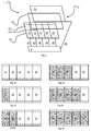
- the Figure 1 illustrates a light device 1 according to the invention.
- the light device 1 comprises a global organic light-emitting diode or OLED 2.
- the OLED 2 has a first reflective face 21 made of aluminum forming an anode 21 of the OLED 2.
- the anode 21 extends continuously over any the length of the OLED 2.
- OLED 2 comprises a second face 22.
- the second face 22 is segmented, namely that it comprises an alternation of cathodes 221 transparent and made of indium-tin oxide or ITO and insulating strips 222 electrically.
- OLED 2 finally comprises a layer 23 formed of a superposition of sub-layers of organic material able to emit amber-colored light when electrically powered.
- the layer 23 is disposed between the first and second faces 21 and 22 so that part of the light it emits passes through the cathode 221 and the other part of this light is reflected by the anode 21 and also passes through the cathode 221.
- Each superposition of a cathode 221, a portion of the layer 23 and a part of the anode 21 located opposite this cathode 221 forms a segment of the global OLED 2 which is selectively activatable. .
- This segment thus itself forms an OLED whose light emitting face is its transparent cathode 221 and whose anode 21 is common to the other segments. It goes without saying that the anode 21 could also be segmented.
- the light device thus comprises five modules 31 to 35, each formed by one of the segments of the global OLED 2.
- the light device further comprises a control module 4 connected on the one hand to each cathode 221 of the modules 31 to 35 by wires 41 to 45 and to the common anode 21 by a wire 46.
- the control module 4 can thus selectively supplying each of the modules 31 to 35, via the wires 41 to 45, so as to selectively switch on the OLEDs of these modules.
- the control module 4 is here arranged in the form of a microcontroller comprising a memory unit (not shown) in which is stored a sequential ignition control of the modules 31 to 35 to achieve a running direction indicator.
- the modules 31 to 35 are arranged in the device 1 so that the OLED of the first module 31 is disposed towards the inside of the vehicle and the OLED of the last module 35 is disposed towards the outside of the vehicle, when the luminous device 1 is mounted in a motor vehicle.
- the control module 4 When the control module receives a command to initiate the sequence for the realization of the running direction indicator, the control module 4 first supplies the module 31 to turn on the OLED of this module 31 ( figure 2b ). After a lapse of time of 200 ms or less, the control module 4 supplies the module 32 to ignite the first organic light-emitting diode of this module 32, while continuing to supply the module 31 (FIG. Figure 2c ). The control module 4 thus continues to sequentially light up the OLEDs of the following modules while keeping the OLEDs of the preceding modules on ( Figures 2d and 2e ), until all the OLEDs of the modules 31 to 35 are lit ( figure 2f ).
- the control module 4 thus implements a sequential and progressive ignition of the OLEDs from the inside to the outside of the vehicle. In this case, the apparent light surface formed by the set of all OLEDs on is continuous. In addition, once all these OLEDs are lit, the control module 4 simultaneously interrupts the power supply of all the OLEDs, then repeats the sequence until a command to interrupt the sequence is received. and thus achieves a regulatory scrolling direction indicator. for example, as defined in the UNECE Regulation No. 6 on direction indicators, paragraph ⁇ 5.6.
- the light device 5 comprises five light modules 51 to 55, each comprising an organic light emitting diode OLED 61 to 65, the OLEDs 61 to 65 being distinct from each other.
- Each OLED 61 to 65 is rotatably mounted about an axis 71 to 75 in the light device 5 and each module comprises an actuator 81 to 85 associated with the OLED 61 to 65 of said module to drive the axis 71 to 75 and selectively bring said OLED into a rest position (P) and into an active position (A).
- OLED 65 is represented in its rest position (P) where its face emission is masked so that little or no light emitted can emerge from the light device 1.
- the OLEDs 61 to 64 are represented in an active position, in which their emission face is visible so as to that the light they emit may emerge from the luminous device 1 to participate in said scrolling direction indicator function.
- the light device 1 comprises a control module 9 which is arranged to control the actuators 71 to 75 so as to sequentially bring each organic light-emitting diode into its active position.
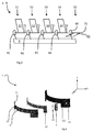
- figure 4 an exploded view of the light device 1 of the figure 1 , in which the segmentation of the global OLED 2 is not represented.
- the light device 1 comprises a support 11 comprising a mounting face 111 extending in three perpendicular directions X, Y and Z in pairs to form a developable surface.
- the global OLED 2 is mounted on the mounting face 111 of the support 11.
- the mounting face 111 has a cylindrical shape, but the invention is not limited to that only form of developable surface.
- OLED 2 has an installation face 21 formed by the anode and a light-emitting face formed by the face 22, opposite the installation face 21.
- the OLED 2 is flexible and is mounted on the mounting face 111 so as to conform to the profile of this mounting face 111 and thus have a shape identical to that of this mounting face 111.
- the OLED 2 is mounted on the support 11 without play.
- OLED 2 is bonded to the mounting face 111 by means of a double-sided adhesive film 12.
- control module 4 is also mounted on the mounting face 111 with the aid of a double-sided film 13.
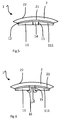
- the device 1 comprises a positioning pin 14 fixed in advance to the installation face 21 of the OLED 2 by the double-sided adhesive film 12.
- the pin 14 is inserted into an orifice 15 of the support 11 so as to position the OLED 2 in a predetermined position on this support 11.
- the positioning pin 14 is provided with a clip 16 allowing, in addition to its positioning function, to secure the OLED 2 to the support 11.
- This method of attachment thus makes it possible to eliminate the double adhesive film. -faces of the figure 4 connecting OLED 2 to support 11.
Landscapes
- Engineering & Computer Science (AREA)
- General Engineering & Computer Science (AREA)
- Physics & Mathematics (AREA)
- Microelectronics & Electronic Packaging (AREA)
- Optics & Photonics (AREA)
- Electroluminescent Light Sources (AREA)
Abstract
Description
- L'invention est relative au domaine des dispositifs d'éclairage et de signalisation pour véhicule automobile.
- De manière connue, ce type de dispositif tend à se complexifier du fait du nombre croissant de fonctions que ces dispositifs ont vocation à mettre en oeuvre. Parmi ces fonctions, on recense notamment la mise en oeuvre d'indicateur de directions de type défilant. Par ailleurs, il existe un besoin de donner à ces dispositifs un caractère esthétique qui contribue notamment à définir l'apparence générale, ou la « signature visuelle », du véhicule considéré, et qui le différencie d'autres véhicules. Par exemple, ce caractère esthétique peut prendre la forme d'un dispositif dont la surface d'émission s'étend selon trois dimensions.
- Dans ce contexte, l'invention vise à présenter un dispositif lumineux pour véhicule automobile qui permette la définition d'une signature visuelle particulière pour ce véhicule tout en présentant une conception, une fiabilité et une compacité optimisées.
- A cet effet, l'invention propose un dispositif lumineux, notamment d'éclairage et/ou de signalisation, pour véhicule automobile, le dispositif lumineux comprenant au moins un support comprenant une face de montage s'étendant selon trois directions perpendiculaires deux à deux, et une diode électroluminescente organique montée sur la face de montage du support.
- La face de montage présente ainsi une surface s'étendant selon trois dimensions. Avantageusement, cette face de montage peut présenter la forme d'une surface développable. Le cas échéant, la diode électroluminescente organique présente une face d'installation et une face d'émission de lumière opposée à la face d'installation, la diode électroluminescente organique étant montée sur le support via sa face d'installation. La diode électroluminescente organique peut être agencée de sorte à ce qu'elle soit apte à émettre de la lumière via sa face d'émission de lumière selon une direction générale sensiblement parallèle à une normale de la face de montage.
- Avantageusement, la diode électroluminescente organique est flexible. De préférence, la diode électroluminescente organique est montée sur la face de montage de sorte à présenter une forme identique à celle de la face de montage. Le cas échéant, la diode électroluminescente organique est montée de sorte à ce qu'aucun jeu ne soit présent entre sa face d'installation et la face de montage du support. En d'autres termes, la diode est montée sur le support sans jeu.
- Dans un mode de réalisation de l'invention, la diode électroluminescente organique est collée sur la face de montage, notamment via sa face d'installation. Si on le souhaite, la diode électroluminescente peut être collée sur la face de montage à l'aide d'un film adhésif double-faces. En variante, la diode électroluminescente organique peut être collée à l'aide d'une colle.
- Avantageusement, le dispositif peut comporter un pion de positionnement fixé à la diode électroluminescente organique et s'insérant dans un orifice du support. Le pion de positionnement peut par exemple être collé à la face d'installation de la diode.
- Si on le souhaite, le pion de positionnement peut être pourvu d'un organe de fixation, par exemple un clip, de la diode électroluminescente organique au support. Le cas échéant, le dispositif peut être dépourvu d'adhésif reliant la diode au support.
- Dans un autre mode de réalisation de l'invention, la diode électroluminescente organique est réalisée directement sur le support. Le dispositif peut être dans ce cas dépourvu de tout moyen de fixation de la diode électroluminescente organique au support. La diode électroluminescente organique peut être par exemple réalisée par un procédé d'évaporation sous vide sur le support, incluant des étapes de métallisation du support et de dépôts de matériau organique émetteur de lumière et d'électrode, ou par un procédé d'impression sous le support.
- Dans un mode de réalisation de l'invention, le dispositif lumineux comprend un premier module comprenant ladite diode électroluminescente organique formant une première diode électroluminescente organique, un deuxième module comprenant une deuxième diode électroluminescente organique et un module de contrôle agencé pour contrôler les premier et deuxième modules de sorte à ce que le dispositif lumineux réalise une fonction d'indicateur de direction défilant.
- Le cas échéant, chaque diode électroluminescente organique peut être apte à émettre de la lumière de couleur ambre.
- Avantageusement, le module de contrôle est agencé pour contrôler les premier et deuxième modules de sorte à ce que les diodes électroluminescentes organiques soient séquentiellement dans une configuration active. On entend par configuration active une configuration de la diode électroluminescente organique dans laquelle de la lumière émise par ladite diode sort du dispositif pour participer à ladite fonction d'indicateur de direction défilant.
- Selon un mode de réalisation de l'invention, chaque diode électroluminescente organique est montée de façon mobile, par exemple en rotation, dans le dispositif lumineux. Avantageusement, chaque module comporte un actionneur associé à la diode électroluminescente organique dudit module pour amener sélectivement ladite diode électroluminescente organique dans une position de repos, dans laquelle la face d'émission de la diode électroluminescente organique est masquée de sorte à ce que peu ou pas de lumière émise par la diode électroluminescente organique puisse sortir du dispositif lumineux, et dans une position active, dans laquelle la face d'émission de la diode électroluminescente organique est visible de sorte à ce que de la lumière émise par la diode électroluminescente organique puisse sortir du dispositif lumineux pour participer à ladite fonction d'indicateur de direction défilant.
- Le cas échéant, le module de contrôle est agencé pour contrôler les actionneurs de sorte à amener séquentiellement chaque diode électroluminescente organique dans sa position active, qui forme ainsi la configuration active.
- Selon un autre mode de réalisation de l'invention, le module de contrôle est agencé pour contrôler l'allumage des premier et deuxième modules de sorte à réaliser un allumage séquentiel des première et deuxième diodes électroluminescentes organiques. Par exemple, le module de contrôle est agencé pour contrôler l'alimentation de chaque diode électroluminescente organique de sorte à allumer ou éteindre cette diode. Le cas échéant, la configuration active de cette diode est lorsqu'elle est allumée.
- Avantageusement, les premier et deuxième modules sont disposés de sorte à ce que la première diode électroluminescente organique soit disposée vers l'intérieur du véhicule et la deuxième diode électroluminescente organique soit disposée vers l'extérieur du véhicule, lorsque le dispositif lumineux est monté dans le véhicule automobile. Le cas échéant, le module de contrôle est agencé pour allumer la première diode électroluminescente organique avant la deuxième diode électroluminescente organique. Eventuellement, le module de contrôle peut être agencé pour que la première diode électroluminescente organique reste allumée lors de l'allumage de la deuxième diode électroluminescente organique. Le module de contrôle met ainsi en oeuvre un allumage séquentiel et progressif des diodes électroluminescentes organiques de l'intérieur vers l'extérieur du véhicule.
- Selon un mode de réalisation de l'invention, la première diode électroluminescente organique est distincte de la deuxième diode électroluminescente organique. Le cas échéant, chaque diode électroluminescente organique comporte une paire d'électrodes, ces paires d'électrodes étant distinctes d'une diode à l'autre.
- En variante, les première et deuxième diodes électroluminescentes organiques peuvent comporter une électrode commune. Le cas échéant, chaque diode électroluminescente organique forme un segment distinct d'une unique diode électroluminescente organique globale du dispositif lumineux. Par exemple, ladite diode électroluminescente organique globale présente une première face comportant une électrode, par exemple une anode, continue sur toute sa longueur, une deuxième face segmentée comportant une alternance d'une pluralité de deuxièmes électrodes et de bandes isolantes électriquement, et une couche de matériau organique apte à émettre de la lumière disposée entre les première et deuxième faces. Chaque segment formé par une partie de la première électrode, une partie de la couche de matériau organique et une deuxième électrode forme ainsi une desdites diodes électroluminescentes organiques. Le cas échéant, la première électrode peut être apte à laisser passer de la lumière, par exemple en étant transparente, et forme une face d'émission de lumière de chaque diode électroluminescente organique et chaque deuxième électrode forme une face d'installation de chaque diode électroluminescente organique. En variante, la première face peut également être segmentée.
- L'invention sera mieux comprise à la lecture de la description détaillée qui va suivre, donnée uniquement à titre d'exemple et faite en référence aux Figures annexées, sur lesquelles :
- La
Figure 1 est une illustration schématique et partielle d'un dispositif lumineux selon l'invention ; - Les
Figures 2a à 2f sont des vue du dispositif lumineux de lafigure 1 mettant en oeuvre un procédé selon l'invention ; - La
Figure 3 est une illustration schématique et partielle d'un dispositif lumineux selon un autre mode de réalisation de l'invention. - La
Figure 4 illustre un vue en éclaté du dispositif lumineux de lafigure 1 selon un premier mode de réalisation de l'invention; - La
Figure 5 est une vue en coupe du dispositif lumineux de lafigure 1 selon un deuxième mode de réalisation ; et - La
Figure 6 est une vue en coupe du dispositif lumineux de lafigure 1 selon un troisième mode de réalisation. - La
Figure 1 illustre un dispositif lumineux 1 selon l'invention. - Le dispositif lumineux 1 comprend une diode électroluminescente organique globale ou OLED 2. L'OLED 2 présente une première face 21 réfléchissante et réalisée en aluminium formant une anode 21 de l'OLED 2. L'anode 21 s'étend de façon continue sur toute la longueur de l'OLED 2.
- L'OLED 2 comprend une deuxième face 22. La deuxième face 22 est segmentée, à savoir qu'elle comporte une alternance de cathodes 221 transparentes et réalisées en oxyde d'indium-étain ou ITO et de bandes isolantes 222 électriquement.
- L'OLED 2 comprend enfin une couche 23 formée d'une superposition de sous-couches de matériau organique aptes à émettre de la lumière de couleur ambre lorsqu'elles sont alimentées électriquement. La couche 23 est disposée entre les première et deuxième faces 21 et 22 de sorte à ce qu'une partie de la lumière qu'elle émet passe à travers la cathode 221 et l'autre partie de cette lumière soit réfléchie par l'anode 21 et passe également à travers la cathode 221.
- Chaque superposition d'une cathode 221, d'une partie de la couche 23 et d'une partie de l'anode 21 situées en vis-à-vis de cette cathode 221 forme un segment de l'OLED globale 2 qui est activable sélectivement. Ce segment forme ainsi lui-même une OLED dont la face d'émission de lumière est sa cathode transparente 221 et dont l'anode 21 est commune aux autres segments. Il va de soi quel l'anode 21 pourrait également être segmentée.
- Le dispositif lumineux comprend ainsi cinq modules 31 à 35, chacun formé par l'un des segments de l'OLED globale 2.
- Le dispositif lumineux comprend en outre un module de contrôle 4 connecté d'une part à chaque cathode 221 des modules 31 à 35 par des fils 41 à 45 et à l'anode commune 21 par un fil 46. Le module de contrôle 4 peut ainsi alimenter de façon sélective chacun des modules 31 à 35, via les fils 41 à 45, de sorte à allumer sélectivement les OLEDs de ces modules.
- Le module de contrôle 4 est ici agencé sous la forme d'un microcontrôleur comportant une unité de mémoire (non représenté) dans lequel est stocké une commande d'allumage séquentiel des modules 31 à 35 pour réaliser un indicateur de direction défilant.
- On a représenté en
figure 2a le dispositif 1 lorsque toutes les OLEDs des modules 31 à 35 sont éteintes et enfigures 2b à 2f ladite séquence d'allumage pour la réalisation de l'indicateur de direction défilant. - Les modules 31 à 35 sont disposés dans le dispositif 1 de sorte à ce que l'OLED du premier module 31 soit disposée vers l'intérieur du véhicule et l'OLED du dernier module 35 soit disposée vers l'extérieur du véhicule, lorsque le dispositif lumineux 1 est monté dans un véhicule automobile.
- Lorsque le module de contrôle reçoit une commande d'initiation de la séquence pour la réalisation de l'indicateur de direction défilant, le module de contrôle 4 alimente en premier lieu le module 31 pour allumer l'OLED de ce module 31 (
figure 2b ). Après un laps de temps de 200 ms ou moins, le module de contrôle 4 alimente le module 32 pour allumer la première diode électroluminescente organique de ce module 32, tout en continuant d'alimenter le module 31 (figure 2c ). Le module de contrôle 4 continue ainsi d'allumer séquentiellement les OLEDs des modules suivants tout en conservant les OLEDs des modules précédents allumées (figures 2d et 2e ), jusqu'à ce que toutes les OLEDs des modules 31 à 35 soient allumées (figure 2f ). Le module de contrôle 4 met ainsi en oeuvre un allumage séquentiel et progressif des OLEDs de l'intérieur vers l'extérieur du véhicule. Le cas échéant, la surface lumineuse apparente formée par l'ensemble de toutes les OLEDs allumée est continue. En outre, une fois toutes ces OLEDs allumées, le module de contrôle 4 interrompt simultanément l'alimentation de toutes les OLEDs, puis réitère la séquence jusqu'à la réception d'une commande d'interruption de la séquence. et réalise ainsi un indicateur de direction défilant réglementaire. par exemple tel que défini dans le règlement UNECE n°6 relatif aux indicateurs de direction, au paragraphe §5.6. - On a représenté en
figure 3 un dispositif lumineux 5 selon un autre mode de réalisation de l'invention. Le dispositif lumineux 5 comporte cinq modules lumineux 51 à 55 comportant chacun une diode électroluminescente organique OLED 61 à 65, les OLEDs 61 à 65 étant distinctes les unes des autres. - Chaque OLED 61 à 65 est montée de façon en rotation autour d'un axe 71 à 75, dans le dispositif lumineux 5 et chaque module comporte un actionneur 81 à 85 associé à l'OLED 61 à 65 dudit module pour entraîner l'axe 71 à 75 et amener sélectivement ladite OLED dans une position de repos (P) et dans une position active (A). L'OLED 65 est représenté dans sa position de repos (P) où sa face d'émission est masquée de sorte à ce que peu ou pas de lumière qu'elle émet puisse sortir du dispositif lumineux 1. Les OLEDs 61 à 64 sont représentés dans une position active, dans laquelle leur face d'émission est visible de sorte à ce que la lumière qu'elles émettent puisse sortir du dispositif lumineux 1 pour participer à ladite fonction d'indicateur de direction défilant.
- Le dispositif lumineux 1 comporte un module de contrôle 9 qui est agencé pour contrôler les actionneurs 71 à 75 de sorte à amener séquentiellement chaque diode électroluminescente organique dans sa position active.
- On a représenté en
figure 4 une vue en éclaté du dispositif lumineux 1 de lafigure 1 , dans laquelle la segmentation de l'OLED globale 2 n'est pas représentée. - Outre l'OLED globale 2 et le module de contrôle 4, le dispositif lumineux 1 comprend un support 11 comprenant une face de montage 111 s'étendant selon trois directions perpendiculaires X, Y et Z deux à deux pour former une surface développable. L'OLED globale 2 est montée sur la face de montage 111 du support 11.
- Dans l'exemple représenté, la face de montage 111 présente une forme cylindrique, sans que l'invention soit toutefois limitée à celle seule forme de surface développable.
- L'OLED 2 présente une face d'installation 21 formée par l'anode et une face d'émission de lumière formée par la face 22, opposée à la face d'installation 21. L'OLED 2 est flexible et est montée sur la face de montage 111 de sorte à se conformer au profil de cette face de montage 111 et ainsi présenter une forme identique à celle de cette face de montage 111. En outre, du fait de la forme développable de la face de montage 111, l'OLED 2 est montée sur le support 11 sans jeu.
- L'OLED 2 est collée sur la face de montage 111 à l'aide d'un film adhésif double-faces 12. En outre, le module de contrôle 4 est également monté sur la face de montage 111 à l'aide d'un film double-faces 13.
- On a représenté en
figure 5 une variante du mode de réalisation de lafigure 4 . Les références des éléments identiques entre ces deux modes de réalisation seront conservées. - Le dispositif 1 comporte un pion de positionnement 14 fixé au préalable à la face d'installation 21 de l'OLED 2 par le film adhésif double-faces 12. Le pion 14 vient s'insérer dans un orifice 15 du support 11 de sorte à positionner l'OLED 2 dans une position prédéterminée sur ce support 11.
- On a représenté en
figure 6 une autre variante du mode de réalisation de lafigure 4 . Les références des éléments identiques entre ces deux modes de réalisations seront conservées. - Dans ce mode de réalisation, le pion de positionnement 14 est pourvu d'un clip 16 permettant, en sus de sa fonction de positionnement, de solidariser l'OLED 2 au support 11. Ce mode de fixation permet ainsi de supprimer le film adhésif doubles-faces de la
figure 4 reliant l'OLED 2 au support 11. - L'invention n'est bien entendu pas limitée aux modes de réalisation présentés et d'autres modes de réalisation pourront apparaître clairement à l'homme du métier sans sortir du cadre la présente invention.
Claims (8)
- Dispositif lumineux (1), pour véhicule automobile, le dispositif lumineux comprenant au moins un support (11) comprenant une face de montage (111) s'étendant selon trois directions (X,Y,Z) perpendiculaires deux à deux, et une diode électroluminescente organique (2) montée sur la face de montage du support.
- Dispositif lumineux (1) selon la revendication 1, dans lequel la diode électroluminescente organique (2) est flexible.
- Dispositif lumineux (1) selon la revendication précédente, dans lequel la diode électroluminescente organique (2) est montée sur la face de montage (111) de sorte à présenter une forme identique à celle de la face de montage.
- Dispositif lumineux (1) selon l'une des revendications précédentes, dans lequel la diode électroluminescente organique (2) est collée sur la face de montage (111).
- Dispositif lumineux (1) selon la revendication précédente, caractérisé en ce que la diode électroluminescente (2) est collée sur la face de montage (111) à l'aide d'un film adhésif double-faces (12).
- Dispositif lumineux (1) selon l'une des revendications précédentes, caractérisé en ce qu'il comporte un pion de positionnement (14) fixé à la diode électroluminescente organique (2) et s'insérant dans un orifice (15) du support (11).
- Dispositif lumineux (1) selon la revendication précédente, caractérisé en ce que le pion de positionnement (14) est pourvu d'organe de fixation (16) de la diode électroluminescente organique (2) au support (11).
- Dispositif lumineux selon l'une des revendications 1 à 3, dans lequel la diode électroluminescente organique est réalisée directement sur le support.
Applications Claiming Priority (1)
| Application Number | Priority Date | Filing Date | Title |
|---|---|---|---|
| FR1558336A FR3040758B1 (fr) | 2015-09-08 | 2015-09-08 | Dispositif lumineux a diode electroluminescente organique |
Publications (2)
| Publication Number | Publication Date |
|---|---|
| EP3141812A1 true EP3141812A1 (fr) | 2017-03-15 |
| EP3141812B1 EP3141812B1 (fr) | 2019-11-13 |
Family
ID=55025163
Family Applications (1)
| Application Number | Title | Priority Date | Filing Date |
|---|---|---|---|
| EP16187032.4A Active EP3141812B1 (fr) | 2015-09-08 | 2016-09-02 | Dispositif lumineux à diode électroluminescente organique |
Country Status (2)
| Country | Link |
|---|---|
| EP (1) | EP3141812B1 (fr) |
| FR (1) | FR3040758B1 (fr) |
Cited By (1)
| Publication number | Priority date | Publication date | Assignee | Title |
|---|---|---|---|---|
| CN109945127A (zh) * | 2017-10-16 | 2019-06-28 | Smr专利责任有限公司 | 标志灯组件及其使用方法 |
Citations (6)
| Publication number | Priority date | Publication date | Assignee | Title |
|---|---|---|---|---|
| DE102007021865A1 (de) * | 2007-05-10 | 2008-11-13 | Automotive Lighting Reutlingen Gmbh | Beleuchtungseinrichtung für ein Fahrzeug |
| DE202011108565U1 (de) * | 2011-12-02 | 2013-03-04 | Bjb Gmbh & Co. Kg | Lampe mit wenigstens einer organischen, lichtemmitierenden Diode |
| DE202013105487U1 (de) * | 2013-12-03 | 2014-01-30 | Odelo Gmbh | Kraftfahrzeugleuchte |
| WO2014065169A1 (fr) * | 2012-10-24 | 2014-05-01 | コニカミノルタ株式会社 | Appareil électroluminescent et son procédé de fabrication |
| EP2884555A2 (fr) * | 2013-12-13 | 2015-06-17 | Universal Display Corporation | OLED sur substrat courbé |
| DE102013225796A1 (de) * | 2013-12-12 | 2015-06-18 | Magna Mirrors Holding Gmbh | Leuchteneinheit für ein Kraftfahrzeug |
-
2015
- 2015-09-08 FR FR1558336A patent/FR3040758B1/fr active Active
-
2016
- 2016-09-02 EP EP16187032.4A patent/EP3141812B1/fr active Active
Patent Citations (7)
| Publication number | Priority date | Publication date | Assignee | Title |
|---|---|---|---|---|
| DE102007021865A1 (de) * | 2007-05-10 | 2008-11-13 | Automotive Lighting Reutlingen Gmbh | Beleuchtungseinrichtung für ein Fahrzeug |
| DE202011108565U1 (de) * | 2011-12-02 | 2013-03-04 | Bjb Gmbh & Co. Kg | Lampe mit wenigstens einer organischen, lichtemmitierenden Diode |
| WO2014065169A1 (fr) * | 2012-10-24 | 2014-05-01 | コニカミノルタ株式会社 | Appareil électroluminescent et son procédé de fabrication |
| US20150280152A1 (en) * | 2012-10-24 | 2015-10-01 | Konica Minolta, Inc. | Luminescent device and method of manufacturing the same |
| DE202013105487U1 (de) * | 2013-12-03 | 2014-01-30 | Odelo Gmbh | Kraftfahrzeugleuchte |
| DE102013225796A1 (de) * | 2013-12-12 | 2015-06-18 | Magna Mirrors Holding Gmbh | Leuchteneinheit für ein Kraftfahrzeug |
| EP2884555A2 (fr) * | 2013-12-13 | 2015-06-17 | Universal Display Corporation | OLED sur substrat courbé |
Cited By (2)
| Publication number | Priority date | Publication date | Assignee | Title |
|---|---|---|---|---|
| CN109945127A (zh) * | 2017-10-16 | 2019-06-28 | Smr专利责任有限公司 | 标志灯组件及其使用方法 |
| CN109945127B (zh) * | 2017-10-16 | 2021-07-23 | Smr专利责任有限公司 | 标志灯组件及其使用方法 |
Also Published As
| Publication number | Publication date |
|---|---|
| FR3040758A1 (fr) | 2017-03-10 |
| EP3141812B1 (fr) | 2019-11-13 |
| FR3040758B1 (fr) | 2019-10-04 |
Similar Documents
| Publication | Publication Date | Title |
|---|---|---|
| FR3040759B1 (fr) | Dispositif lumineux a diode electroluminescente organique | |
| WO2010004470A1 (fr) | Systeme a contacts electriques integres | |
| FR2621539A1 (fr) | Retroviseur pour vehicule automobile | |
| FR3017189A1 (fr) | Module d'eclairage et/ou de signalisation rotatif a source lumineuse fixe | |
| EP3141812B1 (fr) | Dispositif lumineux à diode électroluminescente organique | |
| FR3007342B1 (fr) | Dispositif d'eclairage | |
| EP2950166A1 (fr) | Jeu d'aiguilles d'affichage lumineuses pour objet portable tel qu'une montre ou un instrument de mesure | |
| FR3058102A1 (fr) | Interface de commande capacitive et retroeclairee pour vehicule automobile | |
| FR3022328A1 (fr) | Module d'eclairage et/ou de signalisation rotatif | |
| EP1839944B1 (fr) | Dispositif d'éclairage escamotable automatique pour plaque de police de véhicule | |
| FR3046578A1 (fr) | Dispositif d’eclairage lumineux pour vehicule automobile a reglagle d’orientation | |
| FR2847526A1 (fr) | Plafonnier bi-fonctionnel notamment pour vehicule automobile | |
| EP3502792A1 (fr) | Aiguille electroluminescente, et ensemble a jeu d'aiguilles electroluminescentes | |
| EP3230126A1 (fr) | Dispositif d'éclairage et/ou de signalisation mobile d'accueil pour véhicule automobile associé à la gestion des accès au véhicule | |
| FR3065055B1 (fr) | Dispositif lumineux pour vehicule comportant une oled flexible associee a des moyens electromecaniques de deformation | |
| JPWO2018139202A1 (ja) | 車両用灯具 | |
| FR2933167A1 (fr) | Dispositif d'eclairement de l'environnement d'un vehicule automobile | |
| FR2938482A1 (fr) | Vehicule personnel a equilibrage dynamique | |
| EP2355077A1 (fr) | Dispositif d'affichage lumineux d'une enseigne | |
| EP1765630A1 (fr) | Dispositif d'affichage pour vehicule automobile | |
| FR3065054A1 (fr) | Dispositif de signalisation a base d’oled pour vehicule a effet tridimensionnel | |
| EP3502549A1 (fr) | Module lumineux à éléments électroluminescents à coupure progressive | |
| CH714465B1 (fr) | Aiguille électroluminescente, et ensemble à jeu d'aiguilles électroluminescentes. | |
| FR2899008A1 (fr) | Dispositif d'affichage a ecran a cristaux liquides. | |
| EP0716955A1 (fr) | Dispositif pour l'éclairage d'un ensemble d'équipement montés sur un support commun |
Legal Events
| Date | Code | Title | Description |
|---|---|---|---|
| PUAI | Public reference made under article 153(3) epc to a published international application that has entered the european phase |
Free format text: ORIGINAL CODE: 0009012 |
|
| STAA | Information on the status of an ep patent application or granted ep patent |
Free format text: STATUS: THE APPLICATION HAS BEEN PUBLISHED |
|
| AK | Designated contracting states |
Kind code of ref document: A1 Designated state(s): AL AT BE BG CH CY CZ DE DK EE ES FI FR GB GR HR HU IE IS IT LI LT LU LV MC MK MT NL NO PL PT RO RS SE SI SK SM TR |
|
| AX | Request for extension of the european patent |
Extension state: BA ME |
|
| STAA | Information on the status of an ep patent application or granted ep patent |
Free format text: STATUS: REQUEST FOR EXAMINATION WAS MADE |
|
| 17P | Request for examination filed |
Effective date: 20170803 |
|
| RBV | Designated contracting states (corrected) |
Designated state(s): AL AT BE BG CH CY CZ DE DK EE ES FI FR GB GR HR HU IE IS IT LI LT LU LV MC MK MT NL NO PL PT RO RS SE SI SK SM TR |
|
| RIN1 | Information on inventor provided before grant (corrected) |
Inventor name: HUE, DAVID Inventor name: PATRIZI, STEPHANE Inventor name: RUAT, OLIVIER Inventor name: JIMENEZ, MIGUEL-ANGEL Inventor name: AUFORT, SEBASTIEN Inventor name: ALTERMATT, GUILLAUME Inventor name: JIN, HUI |
|
| REG | Reference to a national code |
Ref country code: DE Ref legal event code: R079 Ref document number: 602016024180 Country of ref document: DE Free format text: PREVIOUS MAIN CLASS: F21V0019000000 Ipc: F21S0041155000 |
|
| GRAP | Despatch of communication of intention to grant a patent |
Free format text: ORIGINAL CODE: EPIDOSNIGR1 |
|
| STAA | Information on the status of an ep patent application or granted ep patent |
Free format text: STATUS: GRANT OF PATENT IS INTENDED |
|
| RIC1 | Information provided on ipc code assigned before grant |
Ipc: F21S 41/155 20180101AFI20190514BHEP Ipc: F21V 19/00 20060101ALI20190514BHEP Ipc: F21S 41/19 20180101ALI20190514BHEP Ipc: F21Y 105/00 20160101ALN20190514BHEP Ipc: F21Y 107/20 20160101ALN20190514BHEP Ipc: F21Y 115/15 20160101ALN20190514BHEP Ipc: F21S 43/19 20180101ALI20190514BHEP Ipc: F21S 43/145 20180101ALI20190514BHEP |
|
| INTG | Intention to grant announced |
Effective date: 20190612 |
|
| GRAS | Grant fee paid |
Free format text: ORIGINAL CODE: EPIDOSNIGR3 |
|
| GRAA | (expected) grant |
Free format text: ORIGINAL CODE: 0009210 |
|
| STAA | Information on the status of an ep patent application or granted ep patent |
Free format text: STATUS: THE PATENT HAS BEEN GRANTED |
|
| AK | Designated contracting states |
Kind code of ref document: B1 Designated state(s): AL AT BE BG CH CY CZ DE DK EE ES FI FR GB GR HR HU IE IS IT LI LT LU LV MC MK MT NL NO PL PT RO RS SE SI SK SM TR |
|
| REG | Reference to a national code |
Ref country code: CH Ref legal event code: EP Ref country code: AT Ref legal event code: REF Ref document number: 1202029 Country of ref document: AT Kind code of ref document: T Effective date: 20191115 |
|
| REG | Reference to a national code |
Ref country code: DE Ref legal event code: R096 Ref document number: 602016024180 Country of ref document: DE |
|
| REG | Reference to a national code |
Ref country code: IE Ref legal event code: FG4D Free format text: LANGUAGE OF EP DOCUMENT: FRENCH |
|
| REG | Reference to a national code |
Ref country code: NL Ref legal event code: MP Effective date: 20191113 |
|
| REG | Reference to a national code |
Ref country code: LT Ref legal event code: MG4D |
|
| PG25 | Lapsed in a contracting state [announced via postgrant information from national office to epo] |
Ref country code: LV Free format text: LAPSE BECAUSE OF FAILURE TO SUBMIT A TRANSLATION OF THE DESCRIPTION OR TO PAY THE FEE WITHIN THE PRESCRIBED TIME-LIMIT Effective date: 20191113 Ref country code: SE Free format text: LAPSE BECAUSE OF FAILURE TO SUBMIT A TRANSLATION OF THE DESCRIPTION OR TO PAY THE FEE WITHIN THE PRESCRIBED TIME-LIMIT Effective date: 20191113 Ref country code: NL Free format text: LAPSE BECAUSE OF FAILURE TO SUBMIT A TRANSLATION OF THE DESCRIPTION OR TO PAY THE FEE WITHIN THE PRESCRIBED TIME-LIMIT Effective date: 20191113 Ref country code: LT Free format text: LAPSE BECAUSE OF FAILURE TO SUBMIT A TRANSLATION OF THE DESCRIPTION OR TO PAY THE FEE WITHIN THE PRESCRIBED TIME-LIMIT Effective date: 20191113 Ref country code: PL Free format text: LAPSE BECAUSE OF FAILURE TO SUBMIT A TRANSLATION OF THE DESCRIPTION OR TO PAY THE FEE WITHIN THE PRESCRIBED TIME-LIMIT Effective date: 20191113 Ref country code: GR Free format text: LAPSE BECAUSE OF FAILURE TO SUBMIT A TRANSLATION OF THE DESCRIPTION OR TO PAY THE FEE WITHIN THE PRESCRIBED TIME-LIMIT Effective date: 20200214 Ref country code: NO Free format text: LAPSE BECAUSE OF FAILURE TO SUBMIT A TRANSLATION OF THE DESCRIPTION OR TO PAY THE FEE WITHIN THE PRESCRIBED TIME-LIMIT Effective date: 20200213 Ref country code: PT Free format text: LAPSE BECAUSE OF FAILURE TO SUBMIT A TRANSLATION OF THE DESCRIPTION OR TO PAY THE FEE WITHIN THE PRESCRIBED TIME-LIMIT Effective date: 20200313 Ref country code: BG Free format text: LAPSE BECAUSE OF FAILURE TO SUBMIT A TRANSLATION OF THE DESCRIPTION OR TO PAY THE FEE WITHIN THE PRESCRIBED TIME-LIMIT Effective date: 20200213 Ref country code: FI Free format text: LAPSE BECAUSE OF FAILURE TO SUBMIT A TRANSLATION OF THE DESCRIPTION OR TO PAY THE FEE WITHIN THE PRESCRIBED TIME-LIMIT Effective date: 20191113 |
|
| PG25 | Lapsed in a contracting state [announced via postgrant information from national office to epo] |
Ref country code: RS Free format text: LAPSE BECAUSE OF FAILURE TO SUBMIT A TRANSLATION OF THE DESCRIPTION OR TO PAY THE FEE WITHIN THE PRESCRIBED TIME-LIMIT Effective date: 20191113 Ref country code: HR Free format text: LAPSE BECAUSE OF FAILURE TO SUBMIT A TRANSLATION OF THE DESCRIPTION OR TO PAY THE FEE WITHIN THE PRESCRIBED TIME-LIMIT Effective date: 20191113 Ref country code: IS Free format text: LAPSE BECAUSE OF FAILURE TO SUBMIT A TRANSLATION OF THE DESCRIPTION OR TO PAY THE FEE WITHIN THE PRESCRIBED TIME-LIMIT Effective date: 20200313 |
|
| PG25 | Lapsed in a contracting state [announced via postgrant information from national office to epo] |
Ref country code: AL Free format text: LAPSE BECAUSE OF FAILURE TO SUBMIT A TRANSLATION OF THE DESCRIPTION OR TO PAY THE FEE WITHIN THE PRESCRIBED TIME-LIMIT Effective date: 20191113 |
|
| PG25 | Lapsed in a contracting state [announced via postgrant information from national office to epo] |
Ref country code: CZ Free format text: LAPSE BECAUSE OF FAILURE TO SUBMIT A TRANSLATION OF THE DESCRIPTION OR TO PAY THE FEE WITHIN THE PRESCRIBED TIME-LIMIT Effective date: 20191113 Ref country code: RO Free format text: LAPSE BECAUSE OF FAILURE TO SUBMIT A TRANSLATION OF THE DESCRIPTION OR TO PAY THE FEE WITHIN THE PRESCRIBED TIME-LIMIT Effective date: 20191113 Ref country code: EE Free format text: LAPSE BECAUSE OF FAILURE TO SUBMIT A TRANSLATION OF THE DESCRIPTION OR TO PAY THE FEE WITHIN THE PRESCRIBED TIME-LIMIT Effective date: 20191113 Ref country code: DK Free format text: LAPSE BECAUSE OF FAILURE TO SUBMIT A TRANSLATION OF THE DESCRIPTION OR TO PAY THE FEE WITHIN THE PRESCRIBED TIME-LIMIT Effective date: 20191113 Ref country code: ES Free format text: LAPSE BECAUSE OF FAILURE TO SUBMIT A TRANSLATION OF THE DESCRIPTION OR TO PAY THE FEE WITHIN THE PRESCRIBED TIME-LIMIT Effective date: 20191113 |
|
| REG | Reference to a national code |
Ref country code: DE Ref legal event code: R097 Ref document number: 602016024180 Country of ref document: DE |
|
| REG | Reference to a national code |
Ref country code: AT Ref legal event code: MK05 Ref document number: 1202029 Country of ref document: AT Kind code of ref document: T Effective date: 20191113 |
|
| PG25 | Lapsed in a contracting state [announced via postgrant information from national office to epo] |
Ref country code: SK Free format text: LAPSE BECAUSE OF FAILURE TO SUBMIT A TRANSLATION OF THE DESCRIPTION OR TO PAY THE FEE WITHIN THE PRESCRIBED TIME-LIMIT Effective date: 20191113 Ref country code: SM Free format text: LAPSE BECAUSE OF FAILURE TO SUBMIT A TRANSLATION OF THE DESCRIPTION OR TO PAY THE FEE WITHIN THE PRESCRIBED TIME-LIMIT Effective date: 20191113 |
|
| PLBE | No opposition filed within time limit |
Free format text: ORIGINAL CODE: 0009261 |
|
| STAA | Information on the status of an ep patent application or granted ep patent |
Free format text: STATUS: NO OPPOSITION FILED WITHIN TIME LIMIT |
|
| 26N | No opposition filed |
Effective date: 20200814 |
|
| PG25 | Lapsed in a contracting state [announced via postgrant information from national office to epo] |
Ref country code: AT Free format text: LAPSE BECAUSE OF FAILURE TO SUBMIT A TRANSLATION OF THE DESCRIPTION OR TO PAY THE FEE WITHIN THE PRESCRIBED TIME-LIMIT Effective date: 20191113 Ref country code: SI Free format text: LAPSE BECAUSE OF FAILURE TO SUBMIT A TRANSLATION OF THE DESCRIPTION OR TO PAY THE FEE WITHIN THE PRESCRIBED TIME-LIMIT Effective date: 20191113 |
|
| PG25 | Lapsed in a contracting state [announced via postgrant information from national office to epo] |
Ref country code: IT Free format text: LAPSE BECAUSE OF FAILURE TO SUBMIT A TRANSLATION OF THE DESCRIPTION OR TO PAY THE FEE WITHIN THE PRESCRIBED TIME-LIMIT Effective date: 20191113 |
|
| PG25 | Lapsed in a contracting state [announced via postgrant information from national office to epo] |
Ref country code: MC Free format text: LAPSE BECAUSE OF FAILURE TO SUBMIT A TRANSLATION OF THE DESCRIPTION OR TO PAY THE FEE WITHIN THE PRESCRIBED TIME-LIMIT Effective date: 20191113 |
|
| REG | Reference to a national code |
Ref country code: CH Ref legal event code: PL |
|
| GBPC | Gb: european patent ceased through non-payment of renewal fee |
Effective date: 20200902 |
|
| REG | Reference to a national code |
Ref country code: BE Ref legal event code: MM Effective date: 20200930 |
|
| PG25 | Lapsed in a contracting state [announced via postgrant information from national office to epo] |
Ref country code: LU Free format text: LAPSE BECAUSE OF NON-PAYMENT OF DUE FEES Effective date: 20200902 |
|
| PG25 | Lapsed in a contracting state [announced via postgrant information from national office to epo] |
Ref country code: LI Free format text: LAPSE BECAUSE OF NON-PAYMENT OF DUE FEES Effective date: 20200930 Ref country code: GB Free format text: LAPSE BECAUSE OF NON-PAYMENT OF DUE FEES Effective date: 20200902 Ref country code: IE Free format text: LAPSE BECAUSE OF NON-PAYMENT OF DUE FEES Effective date: 20200902 Ref country code: BE Free format text: LAPSE BECAUSE OF NON-PAYMENT OF DUE FEES Effective date: 20200930 Ref country code: CH Free format text: LAPSE BECAUSE OF NON-PAYMENT OF DUE FEES Effective date: 20200930 |
|
| PG25 | Lapsed in a contracting state [announced via postgrant information from national office to epo] |
Ref country code: TR Free format text: LAPSE BECAUSE OF FAILURE TO SUBMIT A TRANSLATION OF THE DESCRIPTION OR TO PAY THE FEE WITHIN THE PRESCRIBED TIME-LIMIT Effective date: 20191113 Ref country code: MT Free format text: LAPSE BECAUSE OF FAILURE TO SUBMIT A TRANSLATION OF THE DESCRIPTION OR TO PAY THE FEE WITHIN THE PRESCRIBED TIME-LIMIT Effective date: 20191113 Ref country code: CY Free format text: LAPSE BECAUSE OF FAILURE TO SUBMIT A TRANSLATION OF THE DESCRIPTION OR TO PAY THE FEE WITHIN THE PRESCRIBED TIME-LIMIT Effective date: 20191113 |
|
| PG25 | Lapsed in a contracting state [announced via postgrant information from national office to epo] |
Ref country code: MK Free format text: LAPSE BECAUSE OF FAILURE TO SUBMIT A TRANSLATION OF THE DESCRIPTION OR TO PAY THE FEE WITHIN THE PRESCRIBED TIME-LIMIT Effective date: 20191113 |
|
| P01 | Opt-out of the competence of the unified patent court (upc) registered |
Effective date: 20230528 |
|
| PGFP | Annual fee paid to national office [announced via postgrant information from national office to epo] |
Ref country code: DE Payment date: 20250916 Year of fee payment: 10 |
|
| PGFP | Annual fee paid to national office [announced via postgrant information from national office to epo] |
Ref country code: FR Payment date: 20250929 Year of fee payment: 10 |