EP3141779A2 - Power transmission apparatus - Google Patents
Power transmission apparatus Download PDFInfo
- Publication number
- EP3141779A2 EP3141779A2 EP16187453.2A EP16187453A EP3141779A2 EP 3141779 A2 EP3141779 A2 EP 3141779A2 EP 16187453 A EP16187453 A EP 16187453A EP 3141779 A2 EP3141779 A2 EP 3141779A2
- Authority
- EP
- European Patent Office
- Prior art keywords
- plate
- lubricating oil
- hole
- oil passage
- sowc
- Prior art date
- Legal status (The legal status is an assumption and is not a legal conclusion. Google has not performed a legal analysis and makes no representation as to the accuracy of the status listed.)
- Granted
Links
Images


Classifications
-
- B—PERFORMING OPERATIONS; TRANSPORTING
- B60—VEHICLES IN GENERAL
- B60K—ARRANGEMENT OR MOUNTING OF PROPULSION UNITS OR OF TRANSMISSIONS IN VEHICLES; ARRANGEMENT OR MOUNTING OF PLURAL DIVERSE PRIME-MOVERS IN VEHICLES; AUXILIARY DRIVES FOR VEHICLES; INSTRUMENTATION OR DASHBOARDS FOR VEHICLES; ARRANGEMENTS IN CONNECTION WITH COOLING, AIR INTAKE, GAS EXHAUST OR FUEL SUPPLY OF PROPULSION UNITS IN VEHICLES
- B60K6/00—Arrangement or mounting of plural diverse prime-movers for mutual or common propulsion, e.g. hybrid propulsion systems comprising electric motors and internal combustion engines ; Control systems therefor, i.e. systems controlling two or more prime movers, or controlling one of these prime movers and any of the transmission, drive or drive units Informative references: mechanical gearings with secondary electric drive F16H3/72; arrangements for handling mechanical energy structurally associated with the dynamo-electric machine H02K7/00; machines comprising structurally interrelated motor and generator parts H02K51/00; dynamo-electric machines not otherwise provided for in H02K see H02K99/00
- B60K6/20—Arrangement or mounting of plural diverse prime-movers for mutual or common propulsion, e.g. hybrid propulsion systems comprising electric motors and internal combustion engines ; Control systems therefor, i.e. systems controlling two or more prime movers, or controlling one of these prime movers and any of the transmission, drive or drive units Informative references: mechanical gearings with secondary electric drive F16H3/72; arrangements for handling mechanical energy structurally associated with the dynamo-electric machine H02K7/00; machines comprising structurally interrelated motor and generator parts H02K51/00; dynamo-electric machines not otherwise provided for in H02K see H02K99/00 the prime-movers consisting of electric motors and internal combustion engines, e.g. HEVs
- B60K6/22—Arrangement or mounting of plural diverse prime-movers for mutual or common propulsion, e.g. hybrid propulsion systems comprising electric motors and internal combustion engines ; Control systems therefor, i.e. systems controlling two or more prime movers, or controlling one of these prime movers and any of the transmission, drive or drive units Informative references: mechanical gearings with secondary electric drive F16H3/72; arrangements for handling mechanical energy structurally associated with the dynamo-electric machine H02K7/00; machines comprising structurally interrelated motor and generator parts H02K51/00; dynamo-electric machines not otherwise provided for in H02K see H02K99/00 the prime-movers consisting of electric motors and internal combustion engines, e.g. HEVs characterised by apparatus, components or means specially adapted for HEVs
- B60K6/36—Arrangement or mounting of plural diverse prime-movers for mutual or common propulsion, e.g. hybrid propulsion systems comprising electric motors and internal combustion engines ; Control systems therefor, i.e. systems controlling two or more prime movers, or controlling one of these prime movers and any of the transmission, drive or drive units Informative references: mechanical gearings with secondary electric drive F16H3/72; arrangements for handling mechanical energy structurally associated with the dynamo-electric machine H02K7/00; machines comprising structurally interrelated motor and generator parts H02K51/00; dynamo-electric machines not otherwise provided for in H02K see H02K99/00 the prime-movers consisting of electric motors and internal combustion engines, e.g. HEVs characterised by apparatus, components or means specially adapted for HEVs characterised by the transmission gearings
-
- B—PERFORMING OPERATIONS; TRANSPORTING
- B60—VEHICLES IN GENERAL
- B60K—ARRANGEMENT OR MOUNTING OF PROPULSION UNITS OR OF TRANSMISSIONS IN VEHICLES; ARRANGEMENT OR MOUNTING OF PLURAL DIVERSE PRIME-MOVERS IN VEHICLES; AUXILIARY DRIVES FOR VEHICLES; INSTRUMENTATION OR DASHBOARDS FOR VEHICLES; ARRANGEMENTS IN CONNECTION WITH COOLING, AIR INTAKE, GAS EXHAUST OR FUEL SUPPLY OF PROPULSION UNITS IN VEHICLES
- B60K6/00—Arrangement or mounting of plural diverse prime-movers for mutual or common propulsion, e.g. hybrid propulsion systems comprising electric motors and internal combustion engines ; Control systems therefor, i.e. systems controlling two or more prime movers, or controlling one of these prime movers and any of the transmission, drive or drive units Informative references: mechanical gearings with secondary electric drive F16H3/72; arrangements for handling mechanical energy structurally associated with the dynamo-electric machine H02K7/00; machines comprising structurally interrelated motor and generator parts H02K51/00; dynamo-electric machines not otherwise provided for in H02K see H02K99/00
- B60K6/20—Arrangement or mounting of plural diverse prime-movers for mutual or common propulsion, e.g. hybrid propulsion systems comprising electric motors and internal combustion engines ; Control systems therefor, i.e. systems controlling two or more prime movers, or controlling one of these prime movers and any of the transmission, drive or drive units Informative references: mechanical gearings with secondary electric drive F16H3/72; arrangements for handling mechanical energy structurally associated with the dynamo-electric machine H02K7/00; machines comprising structurally interrelated motor and generator parts H02K51/00; dynamo-electric machines not otherwise provided for in H02K see H02K99/00 the prime-movers consisting of electric motors and internal combustion engines, e.g. HEVs
- B60K6/22—Arrangement or mounting of plural diverse prime-movers for mutual or common propulsion, e.g. hybrid propulsion systems comprising electric motors and internal combustion engines ; Control systems therefor, i.e. systems controlling two or more prime movers, or controlling one of these prime movers and any of the transmission, drive or drive units Informative references: mechanical gearings with secondary electric drive F16H3/72; arrangements for handling mechanical energy structurally associated with the dynamo-electric machine H02K7/00; machines comprising structurally interrelated motor and generator parts H02K51/00; dynamo-electric machines not otherwise provided for in H02K see H02K99/00 the prime-movers consisting of electric motors and internal combustion engines, e.g. HEVs characterised by apparatus, components or means specially adapted for HEVs
- B60K6/38—Arrangement or mounting of plural diverse prime-movers for mutual or common propulsion, e.g. hybrid propulsion systems comprising electric motors and internal combustion engines ; Control systems therefor, i.e. systems controlling two or more prime movers, or controlling one of these prime movers and any of the transmission, drive or drive units Informative references: mechanical gearings with secondary electric drive F16H3/72; arrangements for handling mechanical energy structurally associated with the dynamo-electric machine H02K7/00; machines comprising structurally interrelated motor and generator parts H02K51/00; dynamo-electric machines not otherwise provided for in H02K see H02K99/00 the prime-movers consisting of electric motors and internal combustion engines, e.g. HEVs characterised by apparatus, components or means specially adapted for HEVs characterised by the driveline clutches
- B60K6/383—One-way clutches or freewheel devices
-
- B—PERFORMING OPERATIONS; TRANSPORTING
- B60—VEHICLES IN GENERAL
- B60K—ARRANGEMENT OR MOUNTING OF PROPULSION UNITS OR OF TRANSMISSIONS IN VEHICLES; ARRANGEMENT OR MOUNTING OF PLURAL DIVERSE PRIME-MOVERS IN VEHICLES; AUXILIARY DRIVES FOR VEHICLES; INSTRUMENTATION OR DASHBOARDS FOR VEHICLES; ARRANGEMENTS IN CONNECTION WITH COOLING, AIR INTAKE, GAS EXHAUST OR FUEL SUPPLY OF PROPULSION UNITS IN VEHICLES
- B60K6/00—Arrangement or mounting of plural diverse prime-movers for mutual or common propulsion, e.g. hybrid propulsion systems comprising electric motors and internal combustion engines ; Control systems therefor, i.e. systems controlling two or more prime movers, or controlling one of these prime movers and any of the transmission, drive or drive units Informative references: mechanical gearings with secondary electric drive F16H3/72; arrangements for handling mechanical energy structurally associated with the dynamo-electric machine H02K7/00; machines comprising structurally interrelated motor and generator parts H02K51/00; dynamo-electric machines not otherwise provided for in H02K see H02K99/00
- B60K6/20—Arrangement or mounting of plural diverse prime-movers for mutual or common propulsion, e.g. hybrid propulsion systems comprising electric motors and internal combustion engines ; Control systems therefor, i.e. systems controlling two or more prime movers, or controlling one of these prime movers and any of the transmission, drive or drive units Informative references: mechanical gearings with secondary electric drive F16H3/72; arrangements for handling mechanical energy structurally associated with the dynamo-electric machine H02K7/00; machines comprising structurally interrelated motor and generator parts H02K51/00; dynamo-electric machines not otherwise provided for in H02K see H02K99/00 the prime-movers consisting of electric motors and internal combustion engines, e.g. HEVs
- B60K6/22—Arrangement or mounting of plural diverse prime-movers for mutual or common propulsion, e.g. hybrid propulsion systems comprising electric motors and internal combustion engines ; Control systems therefor, i.e. systems controlling two or more prime movers, or controlling one of these prime movers and any of the transmission, drive or drive units Informative references: mechanical gearings with secondary electric drive F16H3/72; arrangements for handling mechanical energy structurally associated with the dynamo-electric machine H02K7/00; machines comprising structurally interrelated motor and generator parts H02K51/00; dynamo-electric machines not otherwise provided for in H02K see H02K99/00 the prime-movers consisting of electric motors and internal combustion engines, e.g. HEVs characterised by apparatus, components or means specially adapted for HEVs
- B60K6/38—Arrangement or mounting of plural diverse prime-movers for mutual or common propulsion, e.g. hybrid propulsion systems comprising electric motors and internal combustion engines ; Control systems therefor, i.e. systems controlling two or more prime movers, or controlling one of these prime movers and any of the transmission, drive or drive units Informative references: mechanical gearings with secondary electric drive F16H3/72; arrangements for handling mechanical energy structurally associated with the dynamo-electric machine H02K7/00; machines comprising structurally interrelated motor and generator parts H02K51/00; dynamo-electric machines not otherwise provided for in H02K see H02K99/00 the prime-movers consisting of electric motors and internal combustion engines, e.g. HEVs characterised by apparatus, components or means specially adapted for HEVs characterised by the driveline clutches
- B60K6/387—Actuated clutches, i.e. clutches engaged or disengaged by electric, hydraulic or mechanical actuating means
-
- B—PERFORMING OPERATIONS; TRANSPORTING
- B60—VEHICLES IN GENERAL
- B60K—ARRANGEMENT OR MOUNTING OF PROPULSION UNITS OR OF TRANSMISSIONS IN VEHICLES; ARRANGEMENT OR MOUNTING OF PLURAL DIVERSE PRIME-MOVERS IN VEHICLES; AUXILIARY DRIVES FOR VEHICLES; INSTRUMENTATION OR DASHBOARDS FOR VEHICLES; ARRANGEMENTS IN CONNECTION WITH COOLING, AIR INTAKE, GAS EXHAUST OR FUEL SUPPLY OF PROPULSION UNITS IN VEHICLES
- B60K6/00—Arrangement or mounting of plural diverse prime-movers for mutual or common propulsion, e.g. hybrid propulsion systems comprising electric motors and internal combustion engines ; Control systems therefor, i.e. systems controlling two or more prime movers, or controlling one of these prime movers and any of the transmission, drive or drive units Informative references: mechanical gearings with secondary electric drive F16H3/72; arrangements for handling mechanical energy structurally associated with the dynamo-electric machine H02K7/00; machines comprising structurally interrelated motor and generator parts H02K51/00; dynamo-electric machines not otherwise provided for in H02K see H02K99/00
- B60K6/20—Arrangement or mounting of plural diverse prime-movers for mutual or common propulsion, e.g. hybrid propulsion systems comprising electric motors and internal combustion engines ; Control systems therefor, i.e. systems controlling two or more prime movers, or controlling one of these prime movers and any of the transmission, drive or drive units Informative references: mechanical gearings with secondary electric drive F16H3/72; arrangements for handling mechanical energy structurally associated with the dynamo-electric machine H02K7/00; machines comprising structurally interrelated motor and generator parts H02K51/00; dynamo-electric machines not otherwise provided for in H02K see H02K99/00 the prime-movers consisting of electric motors and internal combustion engines, e.g. HEVs
- B60K6/22—Arrangement or mounting of plural diverse prime-movers for mutual or common propulsion, e.g. hybrid propulsion systems comprising electric motors and internal combustion engines ; Control systems therefor, i.e. systems controlling two or more prime movers, or controlling one of these prime movers and any of the transmission, drive or drive units Informative references: mechanical gearings with secondary electric drive F16H3/72; arrangements for handling mechanical energy structurally associated with the dynamo-electric machine H02K7/00; machines comprising structurally interrelated motor and generator parts H02K51/00; dynamo-electric machines not otherwise provided for in H02K see H02K99/00 the prime-movers consisting of electric motors and internal combustion engines, e.g. HEVs characterised by apparatus, components or means specially adapted for HEVs
- B60K6/40—Arrangement or mounting of plural diverse prime-movers for mutual or common propulsion, e.g. hybrid propulsion systems comprising electric motors and internal combustion engines ; Control systems therefor, i.e. systems controlling two or more prime movers, or controlling one of these prime movers and any of the transmission, drive or drive units Informative references: mechanical gearings with secondary electric drive F16H3/72; arrangements for handling mechanical energy structurally associated with the dynamo-electric machine H02K7/00; machines comprising structurally interrelated motor and generator parts H02K51/00; dynamo-electric machines not otherwise provided for in H02K see H02K99/00 the prime-movers consisting of electric motors and internal combustion engines, e.g. HEVs characterised by apparatus, components or means specially adapted for HEVs characterised by the assembly or relative disposition of components
- B60K6/405—Housings
-
- B—PERFORMING OPERATIONS; TRANSPORTING
- B60—VEHICLES IN GENERAL
- B60K—ARRANGEMENT OR MOUNTING OF PROPULSION UNITS OR OF TRANSMISSIONS IN VEHICLES; ARRANGEMENT OR MOUNTING OF PLURAL DIVERSE PRIME-MOVERS IN VEHICLES; AUXILIARY DRIVES FOR VEHICLES; INSTRUMENTATION OR DASHBOARDS FOR VEHICLES; ARRANGEMENTS IN CONNECTION WITH COOLING, AIR INTAKE, GAS EXHAUST OR FUEL SUPPLY OF PROPULSION UNITS IN VEHICLES
- B60K6/00—Arrangement or mounting of plural diverse prime-movers for mutual or common propulsion, e.g. hybrid propulsion systems comprising electric motors and internal combustion engines ; Control systems therefor, i.e. systems controlling two or more prime movers, or controlling one of these prime movers and any of the transmission, drive or drive units Informative references: mechanical gearings with secondary electric drive F16H3/72; arrangements for handling mechanical energy structurally associated with the dynamo-electric machine H02K7/00; machines comprising structurally interrelated motor and generator parts H02K51/00; dynamo-electric machines not otherwise provided for in H02K see H02K99/00
- B60K6/20—Arrangement or mounting of plural diverse prime-movers for mutual or common propulsion, e.g. hybrid propulsion systems comprising electric motors and internal combustion engines ; Control systems therefor, i.e. systems controlling two or more prime movers, or controlling one of these prime movers and any of the transmission, drive or drive units Informative references: mechanical gearings with secondary electric drive F16H3/72; arrangements for handling mechanical energy structurally associated with the dynamo-electric machine H02K7/00; machines comprising structurally interrelated motor and generator parts H02K51/00; dynamo-electric machines not otherwise provided for in H02K see H02K99/00 the prime-movers consisting of electric motors and internal combustion engines, e.g. HEVs
- B60K6/42—Arrangement or mounting of plural diverse prime-movers for mutual or common propulsion, e.g. hybrid propulsion systems comprising electric motors and internal combustion engines ; Control systems therefor, i.e. systems controlling two or more prime movers, or controlling one of these prime movers and any of the transmission, drive or drive units Informative references: mechanical gearings with secondary electric drive F16H3/72; arrangements for handling mechanical energy structurally associated with the dynamo-electric machine H02K7/00; machines comprising structurally interrelated motor and generator parts H02K51/00; dynamo-electric machines not otherwise provided for in H02K see H02K99/00 the prime-movers consisting of electric motors and internal combustion engines, e.g. HEVs characterised by the architecture of the hybrid electric vehicle
- B60K6/44—Series-parallel type
- B60K6/445—Differential gearing distribution type
-
- B—PERFORMING OPERATIONS; TRANSPORTING
- B60—VEHICLES IN GENERAL
- B60K—ARRANGEMENT OR MOUNTING OF PROPULSION UNITS OR OF TRANSMISSIONS IN VEHICLES; ARRANGEMENT OR MOUNTING OF PLURAL DIVERSE PRIME-MOVERS IN VEHICLES; AUXILIARY DRIVES FOR VEHICLES; INSTRUMENTATION OR DASHBOARDS FOR VEHICLES; ARRANGEMENTS IN CONNECTION WITH COOLING, AIR INTAKE, GAS EXHAUST OR FUEL SUPPLY OF PROPULSION UNITS IN VEHICLES
- B60K6/00—Arrangement or mounting of plural diverse prime-movers for mutual or common propulsion, e.g. hybrid propulsion systems comprising electric motors and internal combustion engines ; Control systems therefor, i.e. systems controlling two or more prime movers, or controlling one of these prime movers and any of the transmission, drive or drive units Informative references: mechanical gearings with secondary electric drive F16H3/72; arrangements for handling mechanical energy structurally associated with the dynamo-electric machine H02K7/00; machines comprising structurally interrelated motor and generator parts H02K51/00; dynamo-electric machines not otherwise provided for in H02K see H02K99/00
- B60K6/20—Arrangement or mounting of plural diverse prime-movers for mutual or common propulsion, e.g. hybrid propulsion systems comprising electric motors and internal combustion engines ; Control systems therefor, i.e. systems controlling two or more prime movers, or controlling one of these prime movers and any of the transmission, drive or drive units Informative references: mechanical gearings with secondary electric drive F16H3/72; arrangements for handling mechanical energy structurally associated with the dynamo-electric machine H02K7/00; machines comprising structurally interrelated motor and generator parts H02K51/00; dynamo-electric machines not otherwise provided for in H02K see H02K99/00 the prime-movers consisting of electric motors and internal combustion engines, e.g. HEVs
- B60K6/42—Arrangement or mounting of plural diverse prime-movers for mutual or common propulsion, e.g. hybrid propulsion systems comprising electric motors and internal combustion engines ; Control systems therefor, i.e. systems controlling two or more prime movers, or controlling one of these prime movers and any of the transmission, drive or drive units Informative references: mechanical gearings with secondary electric drive F16H3/72; arrangements for handling mechanical energy structurally associated with the dynamo-electric machine H02K7/00; machines comprising structurally interrelated motor and generator parts H02K51/00; dynamo-electric machines not otherwise provided for in H02K see H02K99/00 the prime-movers consisting of electric motors and internal combustion engines, e.g. HEVs characterised by the architecture of the hybrid electric vehicle
- B60K6/46—Series type
-
- F—MECHANICAL ENGINEERING; LIGHTING; HEATING; WEAPONS; BLASTING
- F16—ENGINEERING ELEMENTS AND UNITS; GENERAL MEASURES FOR PRODUCING AND MAINTAINING EFFECTIVE FUNCTIONING OF MACHINES OR INSTALLATIONS; THERMAL INSULATION IN GENERAL
- F16D—COUPLINGS FOR TRANSMITTING ROTATION; CLUTCHES; BRAKES
- F16D41/00—Freewheels or freewheel clutches
- F16D41/02—Freewheels or freewheel clutches disengaged by contact of a part of or on the freewheel or freewheel clutch with a stationarily-mounted member
-
- F—MECHANICAL ENGINEERING; LIGHTING; HEATING; WEAPONS; BLASTING
- F16—ENGINEERING ELEMENTS AND UNITS; GENERAL MEASURES FOR PRODUCING AND MAINTAINING EFFECTIVE FUNCTIONING OF MACHINES OR INSTALLATIONS; THERMAL INSULATION IN GENERAL
- F16D—COUPLINGS FOR TRANSMITTING ROTATION; CLUTCHES; BRAKES
- F16D41/00—Freewheels or freewheel clutches
- F16D41/06—Freewheels or freewheel clutches with intermediate wedging coupling members between an inner and an outer surface
- F16D41/08—Freewheels or freewheel clutches with intermediate wedging coupling members between an inner and an outer surface with provision for altering the freewheeling action
-
- F—MECHANICAL ENGINEERING; LIGHTING; HEATING; WEAPONS; BLASTING
- F16—ENGINEERING ELEMENTS AND UNITS; GENERAL MEASURES FOR PRODUCING AND MAINTAINING EFFECTIVE FUNCTIONING OF MACHINES OR INSTALLATIONS; THERMAL INSULATION IN GENERAL
- F16D—COUPLINGS FOR TRANSMITTING ROTATION; CLUTCHES; BRAKES
- F16D41/00—Freewheels or freewheel clutches
- F16D41/12—Freewheels or freewheel clutches with hinged pawl co-operating with teeth, cogs, or the like
- F16D41/125—Freewheels or freewheel clutches with hinged pawl co-operating with teeth, cogs, or the like the pawl movement having an axial component
-
- F—MECHANICAL ENGINEERING; LIGHTING; HEATING; WEAPONS; BLASTING
- F16—ENGINEERING ELEMENTS AND UNITS; GENERAL MEASURES FOR PRODUCING AND MAINTAINING EFFECTIVE FUNCTIONING OF MACHINES OR INSTALLATIONS; THERMAL INSULATION IN GENERAL
- F16D—COUPLINGS FOR TRANSMITTING ROTATION; CLUTCHES; BRAKES
- F16D41/00—Freewheels or freewheel clutches
- F16D41/12—Freewheels or freewheel clutches with hinged pawl co-operating with teeth, cogs, or the like
- F16D41/14—Freewheels or freewheel clutches with hinged pawl co-operating with teeth, cogs, or the like the effective stroke of the pawl being adjustable
-
- F—MECHANICAL ENGINEERING; LIGHTING; HEATING; WEAPONS; BLASTING
- F16—ENGINEERING ELEMENTS AND UNITS; GENERAL MEASURES FOR PRODUCING AND MAINTAINING EFFECTIVE FUNCTIONING OF MACHINES OR INSTALLATIONS; THERMAL INSULATION IN GENERAL
- F16H—GEARING
- F16H3/00—Toothed gearings for conveying rotary motion with variable gear ratio or for reversing rotary motion
- F16H3/44—Toothed gearings for conveying rotary motion with variable gear ratio or for reversing rotary motion using gears having orbital motion
- F16H3/72—Toothed gearings for conveying rotary motion with variable gear ratio or for reversing rotary motion using gears having orbital motion with a secondary drive, e.g. regulating motor, in order to vary speed continuously
- F16H3/727—Toothed gearings for conveying rotary motion with variable gear ratio or for reversing rotary motion using gears having orbital motion with a secondary drive, e.g. regulating motor, in order to vary speed continuously with at least two dynamo electric machines for creating an electric power path inside the gearing, e.g. using generator and motor for a variable power torque path
-
- F—MECHANICAL ENGINEERING; LIGHTING; HEATING; WEAPONS; BLASTING
- F16—ENGINEERING ELEMENTS AND UNITS; GENERAL MEASURES FOR PRODUCING AND MAINTAINING EFFECTIVE FUNCTIONING OF MACHINES OR INSTALLATIONS; THERMAL INSULATION IN GENERAL
- F16H—GEARING
- F16H57/00—General details of gearing
- F16H57/02—Gearboxes; Mounting gearing therein
- F16H57/021—Shaft support structures, e.g. partition walls, bearing eyes, casing walls or covers with bearings
-
- F—MECHANICAL ENGINEERING; LIGHTING; HEATING; WEAPONS; BLASTING
- F16—ENGINEERING ELEMENTS AND UNITS; GENERAL MEASURES FOR PRODUCING AND MAINTAINING EFFECTIVE FUNCTIONING OF MACHINES OR INSTALLATIONS; THERMAL INSULATION IN GENERAL
- F16H—GEARING
- F16H57/00—General details of gearing
- F16H57/04—Features relating to lubrication or cooling or heating
- F16H57/042—Guidance of lubricant
- F16H57/0421—Guidance of lubricant on or within the casing, e.g. shields or baffles for collecting lubricant, tubes, pipes, grooves, channels or the like
- F16H57/0424—Lubricant guiding means in the wall of or integrated with the casing, e.g. grooves, channels, holes
-
- F—MECHANICAL ENGINEERING; LIGHTING; HEATING; WEAPONS; BLASTING
- F16—ENGINEERING ELEMENTS AND UNITS; GENERAL MEASURES FOR PRODUCING AND MAINTAINING EFFECTIVE FUNCTIONING OF MACHINES OR INSTALLATIONS; THERMAL INSULATION IN GENERAL
- F16H—GEARING
- F16H57/00—General details of gearing
- F16H57/04—Features relating to lubrication or cooling or heating
- F16H57/0434—Features relating to lubrication or cooling or heating relating to lubrication supply, e.g. pumps ; Pressure control
- F16H57/0436—Pumps
-
- F—MECHANICAL ENGINEERING; LIGHTING; HEATING; WEAPONS; BLASTING
- F16—ENGINEERING ELEMENTS AND UNITS; GENERAL MEASURES FOR PRODUCING AND MAINTAINING EFFECTIVE FUNCTIONING OF MACHINES OR INSTALLATIONS; THERMAL INSULATION IN GENERAL
- F16H—GEARING
- F16H57/00—General details of gearing
- F16H57/04—Features relating to lubrication or cooling or heating
- F16H57/045—Lubricant storage reservoirs, e.g. reservoirs in addition to a gear sump for collecting lubricant in the upper part of a gear case
-
- F—MECHANICAL ENGINEERING; LIGHTING; HEATING; WEAPONS; BLASTING
- F16—ENGINEERING ELEMENTS AND UNITS; GENERAL MEASURES FOR PRODUCING AND MAINTAINING EFFECTIVE FUNCTIONING OF MACHINES OR INSTALLATIONS; THERMAL INSULATION IN GENERAL
- F16H—GEARING
- F16H57/00—General details of gearing
- F16H57/04—Features relating to lubrication or cooling or heating
- F16H57/0467—Elements of gearings to be lubricated, cooled or heated
- F16H57/0473—Friction devices, e.g. clutches or brakes
-
- F—MECHANICAL ENGINEERING; LIGHTING; HEATING; WEAPONS; BLASTING
- F16—ENGINEERING ELEMENTS AND UNITS; GENERAL MEASURES FOR PRODUCING AND MAINTAINING EFFECTIVE FUNCTIONING OF MACHINES OR INSTALLATIONS; THERMAL INSULATION IN GENERAL
- F16H—GEARING
- F16H57/00—General details of gearing
- F16H57/04—Features relating to lubrication or cooling or heating
- F16H57/048—Type of gearings to be lubricated, cooled or heated
- F16H57/0482—Gearings with gears having orbital motion
- F16H57/0483—Axle or inter-axle differentials
-
- F—MECHANICAL ENGINEERING; LIGHTING; HEATING; WEAPONS; BLASTING
- F16—ENGINEERING ELEMENTS AND UNITS; GENERAL MEASURES FOR PRODUCING AND MAINTAINING EFFECTIVE FUNCTIONING OF MACHINES OR INSTALLATIONS; THERMAL INSULATION IN GENERAL
- F16H—GEARING
- F16H57/00—General details of gearing
- F16H57/04—Features relating to lubrication or cooling or heating
- F16H57/048—Type of gearings to be lubricated, cooled or heated
- F16H57/0482—Gearings with gears having orbital motion
- F16H57/0484—Gearings with gears having orbital motion with variable gear ratio or for reversing rotary motion
-
- B—PERFORMING OPERATIONS; TRANSPORTING
- B60—VEHICLES IN GENERAL
- B60K—ARRANGEMENT OR MOUNTING OF PROPULSION UNITS OR OF TRANSMISSIONS IN VEHICLES; ARRANGEMENT OR MOUNTING OF PLURAL DIVERSE PRIME-MOVERS IN VEHICLES; AUXILIARY DRIVES FOR VEHICLES; INSTRUMENTATION OR DASHBOARDS FOR VEHICLES; ARRANGEMENTS IN CONNECTION WITH COOLING, AIR INTAKE, GAS EXHAUST OR FUEL SUPPLY OF PROPULSION UNITS IN VEHICLES
- B60K6/00—Arrangement or mounting of plural diverse prime-movers for mutual or common propulsion, e.g. hybrid propulsion systems comprising electric motors and internal combustion engines ; Control systems therefor, i.e. systems controlling two or more prime movers, or controlling one of these prime movers and any of the transmission, drive or drive units Informative references: mechanical gearings with secondary electric drive F16H3/72; arrangements for handling mechanical energy structurally associated with the dynamo-electric machine H02K7/00; machines comprising structurally interrelated motor and generator parts H02K51/00; dynamo-electric machines not otherwise provided for in H02K see H02K99/00
- B60K6/20—Arrangement or mounting of plural diverse prime-movers for mutual or common propulsion, e.g. hybrid propulsion systems comprising electric motors and internal combustion engines ; Control systems therefor, i.e. systems controlling two or more prime movers, or controlling one of these prime movers and any of the transmission, drive or drive units Informative references: mechanical gearings with secondary electric drive F16H3/72; arrangements for handling mechanical energy structurally associated with the dynamo-electric machine H02K7/00; machines comprising structurally interrelated motor and generator parts H02K51/00; dynamo-electric machines not otherwise provided for in H02K see H02K99/00 the prime-movers consisting of electric motors and internal combustion engines, e.g. HEVs
- B60K6/22—Arrangement or mounting of plural diverse prime-movers for mutual or common propulsion, e.g. hybrid propulsion systems comprising electric motors and internal combustion engines ; Control systems therefor, i.e. systems controlling two or more prime movers, or controlling one of these prime movers and any of the transmission, drive or drive units Informative references: mechanical gearings with secondary electric drive F16H3/72; arrangements for handling mechanical energy structurally associated with the dynamo-electric machine H02K7/00; machines comprising structurally interrelated motor and generator parts H02K51/00; dynamo-electric machines not otherwise provided for in H02K see H02K99/00 the prime-movers consisting of electric motors and internal combustion engines, e.g. HEVs characterised by apparatus, components or means specially adapted for HEVs
- B60K6/36—Arrangement or mounting of plural diverse prime-movers for mutual or common propulsion, e.g. hybrid propulsion systems comprising electric motors and internal combustion engines ; Control systems therefor, i.e. systems controlling two or more prime movers, or controlling one of these prime movers and any of the transmission, drive or drive units Informative references: mechanical gearings with secondary electric drive F16H3/72; arrangements for handling mechanical energy structurally associated with the dynamo-electric machine H02K7/00; machines comprising structurally interrelated motor and generator parts H02K51/00; dynamo-electric machines not otherwise provided for in H02K see H02K99/00 the prime-movers consisting of electric motors and internal combustion engines, e.g. HEVs characterised by apparatus, components or means specially adapted for HEVs characterised by the transmission gearings
- B60K6/365—Arrangement or mounting of plural diverse prime-movers for mutual or common propulsion, e.g. hybrid propulsion systems comprising electric motors and internal combustion engines ; Control systems therefor, i.e. systems controlling two or more prime movers, or controlling one of these prime movers and any of the transmission, drive or drive units Informative references: mechanical gearings with secondary electric drive F16H3/72; arrangements for handling mechanical energy structurally associated with the dynamo-electric machine H02K7/00; machines comprising structurally interrelated motor and generator parts H02K51/00; dynamo-electric machines not otherwise provided for in H02K see H02K99/00 the prime-movers consisting of electric motors and internal combustion engines, e.g. HEVs characterised by apparatus, components or means specially adapted for HEVs characterised by the transmission gearings with the gears having orbital motion
-
- B—PERFORMING OPERATIONS; TRANSPORTING
- B60—VEHICLES IN GENERAL
- B60Y—INDEXING SCHEME RELATING TO ASPECTS CROSS-CUTTING VEHICLE TECHNOLOGY
- B60Y2200/00—Type of vehicle
- B60Y2200/90—Vehicles comprising electric prime movers
- B60Y2200/92—Hybrid vehicles
-
- B—PERFORMING OPERATIONS; TRANSPORTING
- B60—VEHICLES IN GENERAL
- B60Y—INDEXING SCHEME RELATING TO ASPECTS CROSS-CUTTING VEHICLE TECHNOLOGY
- B60Y2400/00—Special features of vehicle units
- B60Y2400/42—Clutches or brakes
- B60Y2400/427—One-way clutches
-
- F—MECHANICAL ENGINEERING; LIGHTING; HEATING; WEAPONS; BLASTING
- F16—ENGINEERING ELEMENTS AND UNITS; GENERAL MEASURES FOR PRODUCING AND MAINTAINING EFFECTIVE FUNCTIONING OF MACHINES OR INSTALLATIONS; THERMAL INSULATION IN GENERAL
- F16D—COUPLINGS FOR TRANSMITTING ROTATION; CLUTCHES; BRAKES
- F16D2300/00—Special features for couplings or clutches
- F16D2300/06—Lubrication details not provided for in group F16D13/74
-
- F—MECHANICAL ENGINEERING; LIGHTING; HEATING; WEAPONS; BLASTING
- F16—ENGINEERING ELEMENTS AND UNITS; GENERAL MEASURES FOR PRODUCING AND MAINTAINING EFFECTIVE FUNCTIONING OF MACHINES OR INSTALLATIONS; THERMAL INSULATION IN GENERAL
- F16H—GEARING
- F16H3/00—Toothed gearings for conveying rotary motion with variable gear ratio or for reversing rotary motion
- F16H3/44—Toothed gearings for conveying rotary motion with variable gear ratio or for reversing rotary motion using gears having orbital motion
- F16H3/72—Toothed gearings for conveying rotary motion with variable gear ratio or for reversing rotary motion using gears having orbital motion with a secondary drive, e.g. regulating motor, in order to vary speed continuously
- F16H3/724—Toothed gearings for conveying rotary motion with variable gear ratio or for reversing rotary motion using gears having orbital motion with a secondary drive, e.g. regulating motor, in order to vary speed continuously using external powered electric machines
-
- F—MECHANICAL ENGINEERING; LIGHTING; HEATING; WEAPONS; BLASTING
- F16—ENGINEERING ELEMENTS AND UNITS; GENERAL MEASURES FOR PRODUCING AND MAINTAINING EFFECTIVE FUNCTIONING OF MACHINES OR INSTALLATIONS; THERMAL INSULATION IN GENERAL
- F16H—GEARING
- F16H57/00—General details of gearing
- F16H57/04—Features relating to lubrication or cooling or heating
- F16H57/0434—Features relating to lubrication or cooling or heating relating to lubrication supply, e.g. pumps ; Pressure control
-
- F—MECHANICAL ENGINEERING; LIGHTING; HEATING; WEAPONS; BLASTING
- F16—ENGINEERING ELEMENTS AND UNITS; GENERAL MEASURES FOR PRODUCING AND MAINTAINING EFFECTIVE FUNCTIONING OF MACHINES OR INSTALLATIONS; THERMAL INSULATION IN GENERAL
- F16H—GEARING
- F16H57/00—General details of gearing
- F16H57/04—Features relating to lubrication or cooling or heating
- F16H57/0467—Elements of gearings to be lubricated, cooled or heated
- F16H57/0476—Electric machines and gearing, i.e. joint lubrication or cooling or heating thereof
-
- Y—GENERAL TAGGING OF NEW TECHNOLOGICAL DEVELOPMENTS; GENERAL TAGGING OF CROSS-SECTIONAL TECHNOLOGIES SPANNING OVER SEVERAL SECTIONS OF THE IPC; TECHNICAL SUBJECTS COVERED BY FORMER USPC CROSS-REFERENCE ART COLLECTIONS [XRACs] AND DIGESTS
- Y02—TECHNOLOGIES OR APPLICATIONS FOR MITIGATION OR ADAPTATION AGAINST CLIMATE CHANGE
- Y02T—CLIMATE CHANGE MITIGATION TECHNOLOGIES RELATED TO TRANSPORTATION
- Y02T10/00—Road transport of goods or passengers
- Y02T10/60—Other road transportation technologies with climate change mitigation effect
- Y02T10/62—Hybrid vehicles
-
- Y—GENERAL TAGGING OF NEW TECHNOLOGICAL DEVELOPMENTS; GENERAL TAGGING OF CROSS-SECTIONAL TECHNOLOGIES SPANNING OVER SEVERAL SECTIONS OF THE IPC; TECHNICAL SUBJECTS COVERED BY FORMER USPC CROSS-REFERENCE ART COLLECTIONS [XRACs] AND DIGESTS
- Y10—TECHNICAL SUBJECTS COVERED BY FORMER USPC
- Y10S—TECHNICAL SUBJECTS COVERED BY FORMER USPC CROSS-REFERENCE ART COLLECTIONS [XRACs] AND DIGESTS
- Y10S903/00—Hybrid electric vehicles, HEVS
- Y10S903/902—Prime movers comprising electrical and internal combustion motors
- Y10S903/903—Prime movers comprising electrical and internal combustion motors having energy storing means, e.g. battery, capacitor
- Y10S903/904—Component specially adapted for hev
- Y10S903/912—Drive line clutch
- Y10S903/913—One way
Definitions
- the present invention relates to a power transmission apparatus.
- hybrid vehicles equipped with engines and motors as driving power sources, and capable of carrying out the electric vehicle (EV) drive using only the motors while the engines are stopped.
- a power transmission apparatus of a hybrid vehicle including a selectable one-way clutch (hereinafter, referred to as an SOWC) as a lock mechanism in a housing case (rear case).
- SOWC selectable one-way clutch
- This power transmission apparatus supplies a lubricating oil into the SOWC by a mechanical oil pump driven by an engine power.
- a power transmission apparatus disclosed in JP 2015-77846 A evenly supplies a lubricating oil to respective components in the housing case by the mechanical oil pump. Hence, it is impossible to intentionally control a supply amount of the lubricating oil to a particular component, specifically, an SOWC. Consequently, depending on the operation condition of the SOWC, deficiency and excess of the lubricating oil occurs inside the SOWC, which might cause an erroneous engagement or deterioration of duration life of the SOWC or the like, for example.
- the present invention provides a power transmission apparatus capable of controlling a supply amount of a lubricating oil supplied to a SOWC.
- a power transmission apparatus for a vehicle includes an engine and a motor as driving power sources.
- the vehicle is configured to be operable to travel using only the motor as the driving power source with the engine stopped.
- the power transmission apparatus includes: an input shaft; a selectable one-way clutch; a housing case; a center support; a lubricating oil reservoir; and an oil passage. Power from the engine is inputted into the input shaft.
- the selectable one-way clutch includes a notch plate, a selector plate, and a pocket plate. The notch plate, the selector plate, and the pocket plate are arranged around the input shaft.
- the notch plate, the selector plate, and the pocket plate are adjacently arranged in an axial direction of the input shaft in an order from the notch plate, to the selector plate, to the pocket plate.
- the selectable one-way clutch is configured such that switching between an engagement state of transmitting a torque between the pocket plate and the notch plate and a non-engagement state of transmitting no torque between the pocket plate and the notch plate is carried out by rotation of the selector plate.
- the selectable one-way clutch is configured to rotate the notch plate along with rotation of the motor.
- the housing case is configured to house the input shaft and the selectable one-way clutch inside the housing case.
- the center support is disposed between an inner surface of the housing case and the input shaft inside the housing case.
- the center support is configured to support the input shaft relative to the housing case.
- the lubricating oil reservoir is disposed in a lubrication passage of the lubricating oil inside the housing case.
- the oil passage is configured to supply the lubricating oil reserved in the lubricating oil reservoir into the selectable one-way clutch.
- the oil passage extends through the pocket plate disposed between the lubricating oil reservoir and the selector plate.
- the selector plate includes a through-hole.
- the through-hole is located at a position where the through-hole is not lined up with the opening of the oil passage in a radial direction and a circumferential direction of the selector plate in the non-engagement state of the selectable one-way clutch, and also at a position where the through-hole is lined up with the opening of the oil passage in the radial direction and the circumferential direction of the selector plate in the engagement state of the selectable one-way clutch.
- the power transmission apparatus of this aspect it is possible to reserve the lubricating oil flowing through the inside of the housing case in the lubricating oil reservoir, and supply the reserved lubricating oil to the selectable one-way clutch through the oil passage.
- the through-hole is not lined up with the opening of the oil passage in the non-engagement state of the selectable one-way clutch, thereby reducing the amount of the lubricating oil supplied from the lubricating oil reservoir to the selectable one-way clutch; and in the engagement state of the selectable one-way clutch, the through-hole is lined up and communicated with the opening of the oil passage, thereby increasing the amount of the lubricating oil supplied from the lubricating oil reservoir to the selectable one-way clutch.
- the lubricating oil reservoir may be disposed adjacent(?) to a portion on the pocket plate in the axial direction of the input shaft, the portion located on an opposite side to the selector plate.
- the notch plate, the selector plate, the pocket plate, and the center support may be adjacently arranged in the axial direction of the input shaft in an order from the notch plate, to the selector plate, the pocket plate, and center support.
- the lubricating oil reservoir may be disposed adjacent (?) to a portion on the center support in the axial direction of the input shaft. The portion may be located on an opposite side to the pocket plate.
- the oil passage may extend through the pocket plate and the center support disposed between the lubricating oil reservoir and the selector plate.
- the power transmission apparatus of the above aspect it is possible to reserve the lubricating oil flowing through the inside of the housing case in the lubricating oil reservoir, and supply the reserved lubricating oil to the selectable one-way clutch through the oil passage.
- the through-hole is not lined up with the opening of the oil passage in the non-engagement state of the selectable one-way clutch, thereby reducing the amount of the lubricating oil supplied from the lubricating oil reservoir to the selectable one-way clutch; and in the engagement state of the selectable one-way clutch, the through-hole is lined up and communicated with the opening of the oil passage, thereby increasing the oil amount of the lubricating oil supplied from the lubricating oil reservoir to the selectable one-way clutch.
- a sectional shape of the oil passage may be the same as a shape of the through-hole, and may be a circular shape.
- each of the sectional shape of the oil passage and the shape of the through-hole is formed in a circular shape, thereby setting a minimum radius of curvature thereof to be the greatest among shapes having the same area; therefore, when the lubricating oil is supplied through the oil passage and the through-hole to the selectable one-way clutch, it is possible to suppress stress concentration onto an end of the oil passage, thus securing strength of the components through which the oil passage is formed.
- the through-hole may be located at an outer peripheral position of the selector plate.
- the oil passage may be located at a position corresponding to the through-hole in the radial direction of the selector plate.
- a sectional shape of the oil passage may be the same as a shape of the through-hole, and may be a laterally long elliptical shape of which shorter sides are arranged in the radial direction of the selector plate.
- the through-hole is formed in a laterally long elliptical shape, and is arranged at a position on the bottom side of the lubricating oil reservoir so as to be corresponding to the formation position of the through-hole, thereby lowering the oil surface level of the lubricating oil reserved in the lubricating oil reservoir, thus adjusting the amount of the lubricating oil in the lubricating oil reservoir.
- a sectional shape of the oil passage may be the same as a shape of the through-hole, and may be a rectangular shape of which longer sides are arranged in the radial direction of the selector plate.
- each of the sectional shape of the oil passage and the shape of the through-hole is formed in a rectangular shape, thereby more rapidly increasing an overlapping area between the through-hole and the opening of the oil passage in the engagement state of the selectable one-way clutch at the beginning of the overlapping of the through-hole with the opening of the oil passage, compared with the case of forming the sectional shape of the oil passage and the shape of the through-hole into another shape (such as a circular shape) with the same area, therefore, it is possible to allow more of the lubricating oil to flow in with a smaller overlapping range.
- the through-hole formed in the selector plate by bringing the through-hole formed in the selector plate to be in communication with or out of communication with the oil passage, it is possible to control the supply amount of the lubricating oil supplied into the selectable one-way clutch.
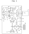
- FIG. 1 is a skeleton view of an entire vehicle equipped with each power transmission apparatus
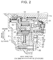
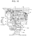
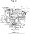
- FIG. 2 , FIG. 10 and FIG. 11 are sectional views showing a part (lower half from an input shaft) of each power transmission apparatus.
- a vehicle equipped with a power transmission apparatus is a hybrid vehicle (HV vehicle) or a plug-in hybrid vehicle (PHV vehicle) including an engine and a motor as a driving power source, and more specifically, a split type (power split type) vehicle using a selectable one way clutch (SOWC) as a lock mechanism.
- HV vehicle hybrid vehicle
- PSV vehicle plug-in hybrid vehicle
- SOWC selectable one way clutch
- the vehicle equipped with the power transmission apparatus includes an engine 1, a first rotary machine (motor) 2, a second rotary machine (motor) 3, a single pinion type planetary gear mechanism 4 that is a first differential mechanism, a double pinion type planetary gear mechanism 5 that is a second differential mechanism, an oil pump 6, a SOWC 7, a rear case 8 that is a housing case, and a center support 91 (see FIG. 2 ).
- the vehicle equipped with the power transmission apparatus of the present embodiment includes: an input shaft 11b that is connected to an output shaft 11a of the engine 1 so as to receive power inputted from the engine 1; a rotor shaft 21 of the first rotary machine 2 that includes the input shaft 11b extending through an inside of the rotor shaft 21, and is relatively rotatable relative to the input shaft 11b; a drive gear 12; a counter driven gear 13; a counter shaft 14; a counter drive gear 15; a differential 16; a ring gear 17; a drive gear 18; and driven wheels 19.
- the power transmission apparatus at least includes: the engine 1; the second rotary machine 3; the input shaft 11b; the oil pump 6; the SOWC 7; the rear case 8; and the center support 91.
- the power transmission apparatus according to the present embodiment has two drive modes: an HV drive mode in which the vehicle travels using only the engine 1, or the engine 1 and the second rotary machine 3 as a driving power source; and an EV drive mode in which the vehicle travels using only the second rotary machine 3 as the driving power source with the engine stopped.
- the planetary gear mechanism 4 is a power split mechanism to split the power outputted from the engine 1 into the first rotary machine 2 side and each driven wheel 19 side (output side), and includes a sun gear, pinion gears, a ring gear, and a carrier (reference numerals thereof are not indicated in FIG. 1 ).
- the sun gear is connected to the rotor shaft 21 of the first rotary machine 2
- the ring gear is connected to the drive gear 12 that is an output element
- the carrier is connected to the output shaft 11a of the engine 1.
- the planetary gear mechanism 5 includes a sun gear 51, a pinion gear 52, a ring gear 53, and a carrier 54.
- the sun gear 51 is connected to the rotor shaft 21 of the first rotary machine 2
- the pinion gear 52 is connected to an oil pump drive gear 62
- the ring gear 53 is connected to a notch plate 72 of the SOWC 7 as described later
- the carrier 54 is connected to the output shaft 11a of the engine 1.
- another pinion gear (a reference numeral thereof is not indicated in FIG.
- the carrier 54 holds these pinion gears in a manner so as to allow these pinion gears to rotate around their own axes as well as rotate around the sun gear.
- the planetary gear mechanism 5 is disposed around the input shaft 11b, and between the input shaft 11b and the SOWC 7.
- the oil pump 6 is a mechanical oil pump to supply a lubricating oil to respective components such as the SOWC 7 disposed inside the rear case 8.
- the oil pump 6 is driven by rotation of the input shaft 11b of the engine 1.
- the oil pump 6 includes a pump body 61, and the oil pump drive gear 62 connected to the pump body 61 and the pinion gear 52.
- the SOWC 7 restricts or permits rotation of a rotary element (the ring gear 53) of the planetary gear mechanism 5 so as to carry out switching between a THS (what does this abbreviation stand for?) mode and an OD (what does this abbreviation stand for?) lock mode, for example, in the HV drive mode.
- the THS mode is a mode in which a reaction force against the power of the engine 1 is generated by the first rotary machine 2 so as to drive the vehicle.
- the OD lock mode is a mode in which rotation of the carrier 54 of the planetary gear mechanism 5 is restricted so as to accelerate the rotation of the engine 1, and output this rotation to an output element (the drive gear 12) from the ring gear of the planetary gear mechanism 4.
- the SOWC 7 is disposed around the input shaft 11b, more specifically, on an outer periphery of the ring gear 53 of the planetary gear mechanism 5.
- the SOWC 7 includes a pocket plate 71 that is a stationary race, the notch plate 72 that is a rotary race, a selector plate 73 that is a switching member, and a snap ring 74 used for integrally assembling these components.
- the pocket plate 71, the notch plate 72, the selector plate 73, and the snap ring 74 are adjacently arranged in the axial direction of the input shaft 11b.
- Each of the pocket plate 71, the notch plate 72, the selector plate 73, and the snap ring 74 is generally formed in an annular shape around the axis of the input shaft 11b.
- axial direction denotes a direction parallel with a direction in which the input shaft 11b extends, and a direction of a rotational axis of a rotary element (such as the planetary gear mechanism 5 and the SOWC 7) in the power transmission apparatus.
- a “radial direction” referred to in the following description denotes a direction orthogonal to the axial direction, and a radial direction of the rotary element in the power transmission apparatus.
- plural pockets recessed in the axial direction of the input shaft 11b are formed in a surface of the pocket plate 71 that faces the selector plate 73, and struts (engagement pieces) 71a (see FIG. 3A and others) are installed thereinside.
- a coil spring (a reference numeral thereof is not indicated in the drawings) to push each strut 71a toward the selector plate 73 side is provided inside the pocket.
- plural notches are formed in a surface of the notch plate 72 that faces the selector plate 73.
- window holes 73b are formed in the selector plate 73.
- the struts 71a are pushed inside the pockets of the pocket plate 71 by portions having no window holes 73b of the selector plate 73, and thus the struts 71a come into a non-engagement state.
- the above “engagement state” denotes a state in which the struts 71a of the pocket plate 71 are in mesh with the notches of the notch plate 72 so that a torque is transmitted between the pocket plate 71 and the notch plate 72.
- the notch plate 72 is rotatable relative to the pocket plate 71 in one direction, but is not rotatable in the other direction.
- the above “non-engagement state” denotes a state in which the struts 71a of the pocket plate 71 are out of mesh with the notches of the notch plate 72, so that no torque is transmitted between the pocket plate 71 and the notch plate 72.
- the notch plate 72 becomes rotatable relative to the pocket plate 71 in both directions.
- the rear case (housing case) 8 houses members, such as the input shaft 11b, the rotor shaft 21, the planetary gear mechanism 5, the oil pump 6, the SOWC 7, and the center support 91, thereinside.
- the center support 91 supports the input shaft 11b and the rotor shaft 21. As shown in FIG. 2 , in the rear case 8, the center support 91 is disposed between an inner surface of the rear case 8 and the input shaft 11b.
- the center support 91 more specifically, a radially outer end of the center support 91 is fixed to the inner surface of the rear case 8 via a fastening member 96, a radially inner end of the center support 91 is fixed to the rotor shaft 21 via a bearing member 95.
- the center support 91 supports the rotor shaft 21 via the bearing member 95.
- the rotor shaft 21 is a hollow shaft, and the input shaft 11b is disposed inside the rotor shaft 21 via a bearing member (a reference numeral thereof is not indicated in FIG. 2 ). Accordingly, the center support 91 also supports the input shaft 11b via the bearing member 95, the rotor shaft 21, and the bearing member inside the rotor shaft 21.
- the center support 91 is generally formed in a disk shape around the axis of the input shaft 11b.
- the drive gear 12 is meshed with the counter driven gear 13.
- the counter shaft 14 is fixed to the counter driven gear 13, and the counter drive gear 15 having a smaller diameter than that of the counter driven gear 13 is fixed to the counter shaft 14.
- the counter drive gear 15 is meshed with the ring gear 17 of the differential 16 so as to output a driving torque from the differential 16 to the right and left driven wheels 19.
- the drive gear 18 is fixed to a rotor shaft (a reference numeral thereof is not indicated in FIG. 1 ) of the second rotary machine 3, and this drive gear 18 is meshed with the counter driven gear 13.
- a differential rotation speed (ratchet engagement rotation speed) of the SOWC to activate the ratchet function is preferably set to be as low as a differential rotation speed required for the performance, but in order to attain this, it is required to supply a sufficient amount of the lubricating oil to the SOWC so as to attenuate the movement of the struts in high differential rotation.
- the differential rotation speed (limit overrun rotation speed) of the SOWC including the above components that might be damaged is preferably set to be as high as a differential rotation speed required for the performance, but in order to attain this, it is required to supply a sufficient amount of the lubricating oil to the SOWC so as to attenuate movement of the struts in high differential rotation.
- the power transmission apparatus is provided with the lubricating oil reservoir 92 to reserve the lubricating oil O in the vicinity of the SOWC 7 so as to supply the lubricating oil O from the lubricating oil reservoir 92 into the SOWC 7, and also control the supply amount of the lubricating oil O by the oil passage 94 used for supplying the lubricating oil O, and a through-hole 73a of the selector plate 73.
- the notch plate 72, the selector plate 73, the pocket plate 71, and the center support 91 are adjacently arranged in this order from one side toward the other side in the axial direction of the input shaft 11b.
- the lubricating oil reservoir 92 is disposed in a lubrication passage of the lubricating oil O in the rear case 8, and also on the center support 91 side opposite to the pocket plate 71.
- the lubricating oil O supplied from the oil pump 6 flows from an axial center (the input shaft 11b, the rotor shaft 21) in the radially outward direction via various paths; and the "lubrication passage of the lubricating oil O" including the lubricating oil reservoir 92 denotes a passage where the lubricating oil O flows in the following order: from the rotor shaft 21, to the bearing member 95 and then to the center support 91. "The center support 91 side opposite to the pocket plate 71" denotes the other side in the axial direction of the input shaft 11b, as shown in FIG. 2 .
- the lubricating oil reservoir 92 is configured to be provided at the downstream of the lubrication passage of the lubricating oil O, that is, radially outward so as to receive the lubricating oil O flowing radially outward by centrifugal force.
- the lubricating oil reservoir 92 is provided at a position close to the SOWC 7 both in the axial direction and in the radial direction of the input shaft 11b.
- the lubricating oil reservoir 92 is a region (space) partitioned by a surface of the center support 91 opposite to the pocket plate 71 and a shielding member 93 covering this surface. More specifically, a groove portion 91a is formed in the surface of the center support 91 opposite to the pocket plate 71, and a predetermined space is provided therein.
- the shielding member 93 formed in a plate-like shape is fixed so as to cover this groove portion 91a.
- the center support 91 is arranged around the input shaft 11b, and thus the groove portion 91a is formed in an annular shape with a predetermined depth.
- the power transmission apparatus is capable of reserving the lubricating oil O flowing through the inside of the rear case 8 with a simple structure.
- the lubricating oil reservoir 92 is shielded by the shielding member 93, thus promoting enhancement of sealing performance thereof.
- Reservation amount of the lubricating oil O reserved in the lubricating oil reservoir 92 can be adjusted by changing the dimension (depth) of the groove portion 91a of the center support 91.
- an oil passage 94 is formed between the lubricating oil reservoir 92 and the SOWC 7.
- the oil passage 94 is so formed as to extend through the center support 91 and the pocket plate 71 arranged between the lubricating oil reservoir 92 and the notch plate 72.
- the oil passage 94 is configured in this manner, thereby enabling the lubricating oil O reserved in the lubricating oil reservoir 92 to be supplied into the SOWC 7, more specifically, between the pocket plate 71 and the selector plate 73, and between the selector plate 73 and the notch plate 72.
- the oil passage 94 is formed in a circular shape having a predetermined diameter at a predetermined position in the center support 91 and the pocket plate 71.
- the through-hole 73a is formed in the selector plate 73 in a manner so as to extend through the selector plate 73 in the axial direction of the input shaft 11b.
- the through-hole 73a is used for adjusting the supply amount of the lubricating oil O from the lubricating oil reservoir 92 to the SOWC 7, and has a shape corresponding to the opening of the oil passage 94.
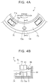
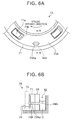
- FIG. 3A , FIG. 4A , FIG. 5A , FIG. 6A , FIG. 7A , and FIG. 8A referred to as below are respective views of the SOWC 7 in FIG. 2 as viewed from the other side to one side in the axial direction of the input shaft 11b.
- Each "stroke opening direction" in these views denotes a rotation direction of the selector plate 73 when the state of the SOWC 7 shifts from the non-engagement state to the engagement state.
- the through-hole 73a according to Embodiment Example 1 is so formed as to extend through the selector plate 73 in the axial direction of the input shaft 11b, that is, in a thickness direction of the selector plate 73 (see FIG. 2 ). As shown in FIG. 3A and FIG.
- the through-hole 73a is formed at a position where the through-hole 73a is not lined up with the opening of the oil passage 94 in the radial direction and the circumferential direction of the selector plate 73 in the non-engagement state of the SOWC 7, and the through-hole 73a is lined up with the opening of the oil passage 94 in the radial direction and the circumferential direction of the selector plate 73 in the engagement state of the SOWC 7.
- the through-hole 73a in the non-engagement state of the SOWC 7, the through-hole 73a is out of communication with the opening of the oil passage 94 in the axial direction of the input shaft 11b, and in the engagement state of the SOWC 7, the through-hole 73a is in communication with the opening of the oil passage 94 in the axial direction of the input shaft 11b.
- each window hole 73b is out of position relative to each strut 71a, and if the SOWC 7 is in the non-engagement state, the through-hole 73a is not in the same phase as that of the opening of the oil passage 94 on the selector plate 73 side (at the same position in the circumferential direction of the selector plate 73), and is not at the same position as that of the opening of the oil passage 94 in the radial direction of the selector plate 73, so that the through-hole 73a is not lined up with this opening. Accordingly, in this case, the supply amount of the lubricating oil O from the lubricating oil reservoir 92 side toward the SOWC 7 side decreases.
- each window hole 73b coincides with the position of each strut 71a, and if the SOWC 7 is in the engagement state, the through-hole 73a is in the same phase as that of the opening of the oil passage 94 on the selector plate 73 side, and is at the same position as that of the opening of the oil passage 94 in the radial direction of the selector plate 73, so that the through-hole 73a is lined up with this opening. Accordingly, in this case, the supply amount of the lubricating oil O from the lubricating oil reservoir 92 side toward the SOWC 7 side becomes increased.
- the through-hole 73a is formed in a circular shape.
- the oil passage 94 also has a circular sectional shape corresponding to the shape of the through-hole 73a.
- the oil passage 94 is formed at a position corresponding to the position of the through-hole 73a in the radial direction of the selector plate 73, that is, at a position where the oil passage 94 communicates with the through-hole 73a in the engagement of the SOWC 7.
- each of the sectional shape of the oil passage 94 and the shape of the through-hole 73a is formed in a circular shape, thereby setting a minimum radius of curvature thereof to be the greatest among various shapes with the same area.
- a through-hole 73Aa according to Embodiment Example 2 has the same function and the same area as those of the through-hole 73a according to Embodiment Example 1, but has a difference in shape from Embodiment Example 1.
- the through-hole 73Aa is not lined up with an opening of an oil passage 94A, and thus the supply amount of the lubricating oil O from the lubricating oil reservoir 92 side toward the SOWC 7A side is decreased.
- the through-hole 73Aa is lined up with the opening of the oil passage 94A, and thus the supply amount of the lubricating oil O from the lubricating oil reservoir 92 side toward the SOWC 7A side is increased.
- the through-hole 73Aa is formed at an outer peripheral position in a selector plate 73A, that is, a position in the selector plate 73A on a bottom side of the lubricating oil reservoir 92.
- the through-hole 73Aa is formed in a laterally long elliptical shape of which shorter sides are arranged in the radial direction of the selector plate 73A.
- the sectional shape of the oil passage 94A is also formed in a laterally long elliptical shape corresponding to the shape of the through-hole 73Aa. As shown in FIG.
- the oil passage 94A is formed at a position corresponding to the through-hole 73Aa in the radial direction of the selector plate 73A, that is, at a position where the oil passage 94A communicates with the through-hole 73Aa in the engagement state of the SOWC 7A.
- the through-hole 73Aa is formed in a laterally long elliptical shape, and the oil passage 94A is arranged at a radially outward position corresponding to the formation position of the through-hole 73Aa, that is, at a position on the bottom side of the lubricating oil reservoir 92, thereby lowering the oil surface level of the lubricating oil O reserved in the lubricating oil reservoir 92, thus adjusting the amount of the lubricating oil O in the lubricating oil reservoir 92.
- the shape of the through-hole 73Aa is formed in a laterally long elliptical shape, and the sectional shape of the oil passage 94A is formed to correspond to this elliptical shape, and thus as shown in FIG. 5B , a height h 2 of the oil passage 94A is lower than a height h 1 of the oil passage 94 according to Embodiment Example 1 (see FIG. 3B ); accordingly, the amount of the lubricating oil O required to be reserved in the lubricating oil reservoir 92 in order to set the oil surface to be higher than the oil passage 94A is reduced. Compared with Embodiment Example 1 (see FIG.
- the aforementioned "height h 1 , h 2 of the oil passage 94, 94A" denotes a height from the bottom surface of the oil passage 94, 94A to the center of the oil passage 94, 94A.
- a through-hole 73Ba according to Embodiment Example 3 has the same function and the same area as those of the through-holes 73a and 73Aa according to Embodiment Examples 1 and 2, but has a difference in shape from Embodiment Examples 1 and 2.
- the through-hole 73Ba in the non-engagement state of an SOWC 7B, the through-hole 73Ba is not lined up with an opening of an oil passage 94B, and thus the supply amount of the lubricating oil O from the lubricating oil reservoir 92 side toward the SOWC 7B side is reduced.
- the through-hole 73Ba is lined up with the opening of the oil passage 94B, and thus the supply amount of the lubricating oil O from the lubricating oil reservoir 92 side toward the SOWC 7B side is increased.
- the through-hole 73Ba is formed in a rectangular, or preferably a trapezoid shape of which longer sides are arranged in the radial direction of the selector plate 73B, and which has slightly round corners.
- the "trapezoid shape” denotes a shape of which two sides facing each other in the radial direction of the selector plate 73B are parallel with each other, and of which two sides facing each other are configured such that one side radially outward of the selector plate 73B is longer than the other side radially inward thereof.
- the sectional shape of the oil passage 94B is formed in a rectangular shape corresponding to the shape of the through-hole 73Ba. As shown in FIG.
- the oil passage 94B is formed at a position corresponding to the through-hole 73Ba in the radial direction of the selector plate 73B, that is, at a position where the oil passage 94B communicates with the through-hole 73Ba in the engagement state of the SOWC 7B.
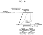
- Each of the sectional shape of the oil passage 94B and the shape of the through-hole 73Ba is formed in a rectangular shape (preferably a trapezoid shape), thereby more rapidly increasing an overlapping area between the through-hole 73Ba and the opening of the oil passage 94B at the beginning of the overlapping of the through-hole 73Ba with the opening of the oil passage 94B in the engagement state of the SOWC 7B, compared with the case of forming each of the sectional shape of the oil passage 94B and the shape of the through-hole 73Ba into another shape (such as a circular shape) with the same area, therefore, it is possible to allow more of the lubricating oil O to flow in with a smaller overlapping range.
- an overlapping area of the through-hole 73a with the oil passage 94 relative to a stroke amount of the selector plate 73 is different from an overlapping area of the through-hole 73Ba with the oil passage 94B relative to a stroke amount of the selector plate 73B.
- the "stroke amount” denotes a rotation rate (movement amount) of the selector plate 73, 73B while the state of the SOWC 7, 7B shifts from the non-engagement state to the engagement state.
- Embodiment Example 3 Compared with Embodiment Example 1 in which the through-hole 73a (in a circular shape) is lined up with the opening (in a circular shape) of the oil passage 94, in the case of Embodiment Example 3 including the through-hole 73Ba and the corresponding oil passage 94B, the through-hole 73Ba (in a rectangular shape) is lined up with the opening (in a rectangular shape) of the oil passage 94B in the engagement state of the SOWC 7B; thus the overlapping area at the same timing (with the same stroke amount) becomes greater than that of Embodiment Example 1. Accordingly, as shown in FIG. 9 , in the case of Embodiment Example 3, the overlapping area is maximised with a smaller stroke than that of Embodiment Example 1. Accordingly, in the case of Embodiment Example 3, it is possible to supply a sufficient amount of the lubricating oil O from the lubricating oil reservoir 92 toward the SOWC 7B side even at the moment when the selector plate 73B
- each of the sectional shape of the oil passage 94B and the through-hole 73Ba is formed to have round corners, thereby suppressing stress concentration onto the end of the oil passage 94B when the lubricating oil O is supplied to the SOWC 7B through the oil passage 94B and the through-hole 73Ba, thus securing strength of the members (the pocket plate 71 and the center support 91 in this case) through which the oil passage 94B is formed.
- the power transmission apparatus having the aforementioned configuration is capable of reserving the lubricating oil O flowing through the inside of the rear case 8 in the lubricating oil reservoir 92, and supplying the reserved lubricating oil O to each SOWC 7, 7A, 7B through each oil passage 94, 94A, 94B.
- the power transmission apparatus includes each through-hole 73a, 73Aa, 73Ba and each corresponding oil passage 94, 94A, 94B, and thus the through-hole 73a, 73Aa, 73Ba is not lined up with the opening of the oil passage 94, 94A, 94B in the non-engagement state of the SOWC 7, 7A, 7B, thereby reducing the amount of the lubricating oil O supplied from the lubricating oil reservoir 92 to the SOWC 7, 7A, 7B.
- the through-hole 73a, 73Aa, 73Ba is lined up and communicated with the opening of the oil passage 94, 94A, 94B, thereby increasing the oil amount of the lubricating oil O supplied from the lubricating oil reservoir 92 to the SOWC 7, 7A, 7B.
- the through-hole 73a, 73Aa, 73Ba corresponding to the oil passage 94, 94A, 94B formed at the predetermined position in the selector plate 73, 73A, 73B that carries out switching between the engagement and non-engagement of the SOWC 7, 7A, 7B so as to bring the through-hole 73a, 73Aa, 73Ba into communication or out of communication with the oil passage 94, 94A, 94B, thereby controlling the amount of the lubricating oil O supplied from the lubricating oil reservoir 92.
- a sufficient amount of the lubricating oil O is supplied from the lubricating oil reservoir 92 into the SOWC 7, 7A, 7B by the internal negative pressure generated by the differential rotation of the SOWC 7, 7A, 7B, thus reducing the ratchet engagement rotation speed. Since the internal negative pressure is higher during the high differential rotation of the SOWC 7, 7A, 7B, it is possible to supply more of the lubricating oil O into the SOWC 7, 7A, 7B than during the low differential rotation of the SOWC 7, 7A, 7B.
- the amount of the lubricating oil O supplied from the lubricating oil reservoir 92 to the SOWC 7, 7A, 7B is reduced even if the selector plate 73, 73A, 73B comes to the engagement position due to malfunction. Accordingly, if the SOWC 7, 7A, 7B comes into the engagement state during the low differential rotation thereof, it is possible to suppress an excessive supply of the lubricating oil O, and prevent deterioration of the engagement reliability.
- a sufficient amount of the lubricating oil O is supplied from the lubricating oil reservoir 92 into the SOWC 7, 7A, 7B by the internal negative pressure generated by the differential rotation of the SOWC 7, 7A, 7B, thereby increasing the limit overrun rotation speed. Since the internal negative pressure is higher during the high differential rotation of the SOWC 7, 7A, 7B, it is possible to supply more of the lubricating oil O into the SOWC 7, 7A, 7B than that during the low differential rotation of the SOWC 7, 7A, 7B.
- the power transmission apparatus is capable of solving insufficiency of the lubricating oil during the EV drive in addition to the aforementioned Problems 1 to 3. Specifically, in the power transmission apparatus of the related art, during the EV drive, the mechanical oil pump is stopped along with the stop of the engine, and thus it is impossible to sufficiently supply the lubricating oil to the SOWC, and thus seizing might be caused to the SOWC if the supplied lubricating oil amount is excessively small.
- the power transmission apparatus according to the present embodiment is different from the first embodiment in formation positions of the lubricating oil reservoir 92 and the oil passage 94.
- the other configurations are the same as those of the first embodiment.
- the shape of the through-hole 73a and the sectional shape of the oil passage 94 will be described based on the assumption of the aforementioned Embodiment Example 1 (see FIG. 3A to FIG. 4B ), but Embodiment Examples 2, 3 may also be applicable.
- the notch plate 72, the selector plate 73, a pocket plate 71C, and a center support 91C are adjacently arranged in this order from one side to the other side in the axial direction of the input shaft 11b.
- a lubricating oil reservoir 92C is disposed in the lubrication passage of the lubricating oil O in the rear case 8, and also on the pocket plate 71C opposite to the selector plate 73.
- the "lubrication passage of the lubricating oil O" including the lubricating oil reservoir 92C denotes a passage where the lubricating oil O flows in order from the rotor shaft 21, to the bearing member 95 and then to the center support 91C, as with the first embodiment.
- "On the pocket plate 71C opposite to the selector plate 73” denotes the other side thereof in the axial direction of the input shaft 11b, as shown in FIG. 10 .
- the lubricating oil reservoir 92C is configured to be provided downstream of the lubrication passage of the lubricating oil O, that is, radially outward so as to receive the lubricating oil O flowing radially outward by centrifugal force.
- the lubricating oil reservoir 92C is provided at a position close to the SOWC 7C both in the axial direction and in the radial direction of the input shaft 11b.
- the lubricating oil reservoir 92C is a region (space) partitioned by a region in the pocket plate 71C and a region in the center support 91C that face each other. More specifically, as shown in FIG. 10 , the pocket plate 71C and the center support 91C are adjacently disposed in one partial region of the pocket plate 71C and the center support 91C in the axial direction of the input shaft 11b, and the other partial region thereof are so disposed as to face each other with a predetermined distance therebetween. Specifically, the pocket plate 71C and the center support 91C are adjacently disposed in their regions (radially outward regions) that are fastened together with the fastening member 96.
- the pocket plate 71C and the center support 91C are so disposed as to face each other with a predetermined space therebetween in the axial direction of the input shaft 11b in their regions radially inward of their regions fastened together with the fastening member 96.
- the space formed by the pocket plate 71C and the center support 91C is set to be the lubricating oil reservoir 92C.
- the power transmission apparatus is capable of reserving the lubricating oil O flowing through the inside of the rear case 8 with a simple structure without using any additional member.
- a reservation amount of the lubricating oil O reserved in the lubricating oil reservoir 92C can be adjusted by changing the dimension of the space formed by the pocket plate 71C and the center support 91C.
- an oil passage 94 is formed between the lubricating oil reservoir 92C and the SOWC 7C.
- the oil passage 94 is formed so as to extend through the pocket plate 71C arranged between the lubricating oil reservoir 92C and the notch plate 72.
- the oil passage 94 is formed in this manner, thereby enabling the lubricating oil O reserved in the lubricating oil reservoir 92C to be supplied into the SOWC 7C, more specifically, between the pocket plate 71C and the selector plate 73, and between the selector plate 73 and the notch plate 72.
- the oil passage 94 is formed in a circular shape having a predetermined diameter at a predetermined position in the pocket plate 71C in FIG. 10 .
- the oil passage 94 is not formed to extend parallel with the axial direction of the input shaft 11b, but formed to be inclined relative to the radial direction of the input shaft 11b, as is different from the aforementioned first embodiment (see FIG. 2 ).
- the oil passage 94 includes a first opening 94a opening toward the notch plate 72 side, and a second opening 94b opening toward the lubricating oil reservoir 92C side, and the second opening 94b is formed more radially outward than the first opening 94a.
- the lubricating oil O flows from radially inward to radially outward; therefore, it is preferable to supply the lubricating oil O as radially inward as possible of the SOWC 7C.
- the oil passage 94 is formed to be parallel, it is necessary to reserve the lubricating oil O at a higher position of the lubricating oil reservoir 92C.
- the oil passage 94 is so formed as to have a difference in height relative to an oil surface of the lubricating oil O of the lubricating oil reservoir 92C, thereby causing the oil passage 94 to be inclined. Accordingly, even if the amount of the lubricating oil O reserved in the lubricating oil reservoir 92C is smaller, it is possible to efficiently supply the lubricating oil O radially inward of the SOWC 7C, thus promoting enhancement of the lubrication efficiency relative to the SOWC 7C.
- the oil passage 94 is formed to have a difference in height relative to the oil surface so as to adjust the oil surface of the lubricating oil O in the lubricating oil reservoir 92C to be lower, thereby preventing an increase in agitation loss and deterioration of fuel efficiency.
- the power transmission apparatus according to the present embodiment is different from the first embodiment in formation positions of the lubricating oil reservoir 92 and the oil passage 94, and the other configurations are the same as those of the first embodiment.
- the shape of the through-hole 73a and the sectional shape of the oil passage 94 will be described based on the assumption of the aforementioned Embodiment Example 1 (see FIG. 3A to FIG. 4B ), but Embodiment Examples 2, 3 may also be applicable.
- a center support 91D, the notch plate 72, the selector plate 73, and a pocket plate 71D are adjacently arranged in this order from the other side to one side in the axial direction of the input shaft 11b.
- the power transmission apparatus according to the present embodiment has a reverse arrangement of the pocket plate 71D and the notch plate 72 in the axial direction of the input shaft 11b to the arrangement thereof in the first embodiment (see FIG. 2 ).
- a lubricating oil reservoir 92D is disposed in the lubrication passage of the lubricating oil O in the rear case 8, and also on the pocket plate 71D opposite to the selector plate 73.
- the "lubrication passage of the lubricating oil O" including the lubricating oil reservoir 92D denotes a passage where the lubricating oil O flows from the input shaft 11b, to the sun gear 51, to the pinion gear 52, and to a ring gear 53D in this order, or a passage where the lubricating oil O flows from the input shaft 11b, to the carrier 54, and to the ring gear 53D in this order.
- an oil passage 53Db is formed in the ring gear 53D so as to introduce the lubricating oil O flowing through the lubrication passage into the lubricating oil reservoir 92D.
- the lubricating oil O flowing through the lubrication passage flows in the aforementioned lubrication passage radially outward by centrifugal force, and is reserved in the lubricating oil reservoir 92D through the oil passage 53Db of the ring gear 53D.
- the lubricating oil reservoir 92D is configured to be provided at the downstream of the lubrication passage of the lubricating oil O, that is, radially outward, as shown in FIG. 11 , so as to receive the lubricating oil O flowing radially outward by centrifugal force.
- the lubricating oil reservoir 92D is provided at a position close to the SOWC 7D both in the axial direction and in the radial direction of the input shaft 11b.
- the lubricating oil reservoir 92D is a region (space) partitioned by a surface of the pocket plate 71D on an opposite side to the notch plate 72 and a shielding member 93D facing this surface. More specifically, to the surface of the pocket plate 71D on the opposite side to the notch plate 72, there is fixed the shielding member 93D in a plate-like shape including a bent portion 93Da that closes a radially outward side of the shielding member 93D, and opens a radially inward side thereof.
- the space formed by the shielding member 93D and the surface of the pocket plate 71D on the opposite side to the notch plate 72 is set to be the lubricating oil reservoir 92D.
- the power transmission apparatus is capable of reserving the lubricating oil O flowing through the inside of the rear case 8 with a simple structure.
- the amount of the lubricating oil O reserved in the lubricating oil reservoir 92D can be adjusted by changing the position of the bent portion 93Da of the shielding member 93D.
- an oil passage 94 is formed between the lubricating oil reservoir 92D and the SOWC 7D.
- the oil passage 94 is formed so as to extend through the pocket plate 71D arranged between the lubricating oil reservoir 92D and the notch plate 72.
- the oil passage 94 is formed in this manner, thereby enabling the lubricating oil O reserved in the lubricating oil reservoir 92D to be supplied into the SOWC 7D, more specifically, between the pocket plate 71D and the selector plate 73, and between the selector plate 73 and the notch plate 72.
- the oil passage 94 is formed in a circular shape having a predetermined diameter at a predetermined position in the pocket plate 71D in FIG. 11 .
- the notch plate 72 is slidingly assembled to the ring gear 53D from the other side to one side in the axial direction of the input shaft 11b; but for example, in the case of the SOWC 7 of the first embodiment and the SOWC 7C of the second embodiment, as shown in FIG. 2 and FIG. 10 , the notch plate 72 is disposed on one side in the axial direction of the input shaft 11b relative to the pocket plate 71, 71C, so that the spline 53a formed on the outer periphery of the ring gear 53 becomes longer, which requires a longer time for the assembly.
- the notch plate 72 is disposed on the other side in the axial direction of the input shaft 11b relative to the pocket plates 71D, and thus the spline 53Da formed on the outer periphery of the ring gear 53D is shorter than the SOWC 7 and the SOWC 7C according to the first and the second embodiments, thus enhancing assemblability.
- a power transmission apparatus includes: an input shaft; a selectable one-way clutch; a housing case; a center support; a lubricating oil reservoir; and an oil passage.
- the oil passage extends through a pocket plate disposed between the lubricating oil reservoir and a selector plate.
- the selector plate includes a through-hole.
- the through-hole is located at a position where the through-hole is not lined up with the opening of the oil passage in a radial direction and a circumferential direction of the selector plate in the non-engagement state of the selectable one-way clutch, and also at a position where the through-hole is lined up with the opening of the oil passage in the radial direction and the circumferential direction of the selector plate in the engagement state of the selectable one-way clutch.
- each power transmission apparatus has been more specifically explained by describing the embodiments for carrying out the present invention, and the gist of the present invention is not intended to be limited to the above descriptions, and it shall be construed broadly based on the description of the scope of the claims. Moreover, it is needless to mention that various changes, modifications, and others that are made based on these descriptions may be included in the gist of the present invention.
Abstract
Description
- The present invention relates to a power transmission apparatus.
- There have been known hybrid vehicles (HV vehicles) equipped with engines and motors as driving power sources, and capable of carrying out the electric vehicle (EV) drive using only the motors while the engines are stopped. For example, Japanese Patent Application Publication No.
2015-77846 - A power transmission apparatus disclosed in
JP 2015-77846 A - The present invention provides a power transmission apparatus capable of controlling a supply amount of a lubricating oil supplied to a SOWC.
- A power transmission apparatus for a vehicle according to one aspect of the present invention is provided. The vehicle includes an engine and a motor as driving power sources. The vehicle is configured to be operable to travel using only the motor as the driving power source with the engine stopped. The power transmission apparatus includes: an input shaft; a selectable one-way clutch; a housing case; a center support; a lubricating oil reservoir; and an oil passage. Power from the engine is inputted into the input shaft. The selectable one-way clutch includes a notch plate, a selector plate, and a pocket plate. The notch plate, the selector plate, and the pocket plate are arranged around the input shaft. The notch plate, the selector plate, and the pocket plate are adjacently arranged in an axial direction of the input shaft in an order from the notch plate, to the selector plate, to the pocket plate. The selectable one-way clutch is configured such that switching between an engagement state of transmitting a torque between the pocket plate and the notch plate and a non-engagement state of transmitting no torque between the pocket plate and the notch plate is carried out by rotation of the selector plate. The selectable one-way clutch is configured to rotate the notch plate along with rotation of the motor. The housing case is configured to house the input shaft and the selectable one-way clutch inside the housing case. The center support is disposed between an inner surface of the housing case and the input shaft inside the housing case. The center support is configured to support the input shaft relative to the housing case. The lubricating oil reservoir is disposed in a lubrication passage of the lubricating oil inside the housing case. The oil passage is configured to supply the lubricating oil reserved in the lubricating oil reservoir into the selectable one-way clutch. The oil passage extends through the pocket plate disposed between the lubricating oil reservoir and the selector plate. The selector plate includes a through-hole. The through-hole is located at a position where the through-hole is not lined up with the opening of the oil passage in a radial direction and a circumferential direction of the selector plate in the non-engagement state of the selectable one-way clutch, and also at a position where the through-hole is lined up with the opening of the oil passage in the radial direction and the circumferential direction of the selector plate in the engagement state of the selectable one-way clutch.
- According to the power transmission apparatus of this aspect, it is possible to reserve the lubricating oil flowing through the inside of the housing case in the lubricating oil reservoir, and supply the reserved lubricating oil to the selectable one-way clutch through the oil passage. In the power transmission apparatus, the through-hole is not lined up with the opening of the oil passage in the non-engagement state of the selectable one-way clutch, thereby reducing the amount of the lubricating oil supplied from the lubricating oil reservoir to the selectable one-way clutch; and in the engagement state of the selectable one-way clutch, the through-hole is lined up and communicated with the opening of the oil passage, thereby increasing the amount of the lubricating oil supplied from the lubricating oil reservoir to the selectable one-way clutch.
- In the power transmission apparatus according to the above aspect, the lubricating oil reservoir may be disposed adjacent(?) to a portion on the pocket plate in the axial direction of the input shaft, the portion located on an opposite side to the selector plate. In the power transmission apparatus according to the above aspect, the notch plate, the selector plate, the pocket plate, and the center support may be adjacently arranged in the axial direction of the input shaft in an order from the notch plate, to the selector plate, the pocket plate, and center support. The lubricating oil reservoir may be disposed adjacent (?) to a portion on the center support in the axial direction of the input shaft. The portion may be located on an opposite side to the pocket plate. The oil passage may extend through the pocket plate and the center support disposed between the lubricating oil reservoir and the selector plate.
- According to the power transmission apparatus of the above aspect, it is possible to reserve the lubricating oil flowing through the inside of the housing case in the lubricating oil reservoir, and supply the reserved lubricating oil to the selectable one-way clutch through the oil passage. In the power transmission apparatus, the through-hole is not lined up with the opening of the oil passage in the non-engagement state of the selectable one-way clutch, thereby reducing the amount of the lubricating oil supplied from the lubricating oil reservoir to the selectable one-way clutch; and in the engagement state of the selectable one-way clutch, the through-hole is lined up and communicated with the opening of the oil passage, thereby increasing the oil amount of the lubricating oil supplied from the lubricating oil reservoir to the selectable one-way clutch.
- In the power transmission apparatus according to the above aspect, a sectional shape of the oil passage may be the same as a shape of the through-hole, and may be a circular shape.
- According to the power transmission apparatus of this aspect, each of the sectional shape of the oil passage and the shape of the through-hole is formed in a circular shape, thereby setting a minimum radius of curvature thereof to be the greatest among shapes having the same area; therefore, when the lubricating oil is supplied through the oil passage and the through-hole to the selectable one-way clutch, it is possible to suppress stress concentration onto an end of the oil passage, thus securing strength of the components through which the oil passage is formed.
- In the power transmission apparatus according to the above aspect, the through-hole may be located at an outer peripheral position of the selector plate. The oil passage may be located at a position corresponding to the through-hole in the radial direction of the selector plate. A sectional shape of the oil passage may be the same as a shape of the through-hole, and may be a laterally long elliptical shape of which shorter sides are arranged in the radial direction of the selector plate.
- According to the power transmission apparatus of the above aspect, the through-hole is formed in a laterally long elliptical shape, and is arranged at a position on the bottom side of the lubricating oil reservoir so as to be corresponding to the formation position of the through-hole, thereby lowering the oil surface level of the lubricating oil reserved in the lubricating oil reservoir, thus adjusting the amount of the lubricating oil in the lubricating oil reservoir.
- In the power transmission apparatus according to the above aspect, a sectional shape of the oil passage may be the same as a shape of the through-hole, and may be a rectangular shape of which longer sides are arranged in the radial direction of the selector plate.
- According to the power transmission apparatus of this aspect, each of the sectional shape of the oil passage and the shape of the through-hole is formed in a rectangular shape, thereby more rapidly increasing an overlapping area between the through-hole and the opening of the oil passage in the engagement state of the selectable one-way clutch at the beginning of the overlapping of the through-hole with the opening of the oil passage, compared with the case of forming the sectional shape of the oil passage and the shape of the through-hole into another shape (such as a circular shape) with the same area, therefore, it is possible to allow more of the lubricating oil to flow in with a smaller overlapping range.
- According to the power transmission apparatus of the above aspect, by bringing the through-hole formed in the selector plate to be in communication with or out of communication with the oil passage, it is possible to control the supply amount of the lubricating oil supplied into the selectable one-way clutch.
- Features, advantages, and technical and industrial significance of exemplary embodiments of the invention will be described below with reference to the accompanying drawings, in which like numerals denote like elements, and wherein:
-
FIG. 1 is a skeleton view of a vehicle equipped with each power transmission apparatus according to first to third embodiments of the present invention; -
FIG. 2 is a sectional view showing a configuration of the power transmission apparatus according to the first embodiment of the present invention; -
FIG. 3A is a view showing Embodiment Example 1 of a selectable one-way clutch of each power transmission apparatus according to the first to the third embodiments of the present invention, and a view showing respective components in a non-engagement state; -
FIG. 3B is a sectional view taken along line A-A ofFIG. 3A ; -
FIG. 4A is a view showing Embodiment Example 1 of the selectable one-way clutch of each power transmission apparatus according to the first to the third embodiments of the present invention, and a view showing respective components in the engagement state; -
FIG. 4B is a sectional view taken along line A-A ofFIG. 4A ; -
FIG. 5A is a view showing Embodiment Example 2 of the selectable one-way clutch of each power transmission apparatus according to the first to the third embodiments of the present invention, and a view showing respective components in the non-engagement state; -
FIG. 5B is a sectional view taken along line A-A ofFIG. 5A ; -
FIG. 6A is a view showing Embodiment Example 2 of the selectable one-way clutch of each power transmission apparatus according to the first to the third embodiments of the present invention, and a view showing respective components in the engagement state; -
FIG. 6B is a sectional view taken along line A-A ofFIG. 6A ; -
FIG. 7A is a view showing Embodiment Example 3 of the selectable one-way clutch of each power transmission apparatus according to the first to the third embodiments of the present invention, and a view showing respective components in the non-engagement state; -
FIG. 7B is a sectional view taken along line A-A ofFIG. 7A ; -
FIG. 8A is a view showing Embodiment Example 3 of the selectable one-way clutch of each power transmission apparatus according to the first to the third embodiments of the present invention, and a view showing respective components in the engagement state; -
FIG. 8B is a sectional view taken along line A-A ofFIG. 8A ; -
FIG. 9 is a graph showing each relation between an overlapping area with an oil passage and a stroke amount in the engagement state with respect to Embodiment Example 1 and Embodiment Example 3 of the selectable one-way clutch of each power transmission apparatus according to the first to the third embodiments of the present invention; -
FIG. 10 is a sectional view showing a configuration of the power transmission apparatus according to the second embodiment of the present invention; and -
FIG. 11 is a sectional view showing the configuration of the power transmission apparatus according to the third embodiment of the present invention. - Each power transmission apparatus according to embodiments of the present invention will be described with reference to
FIG. 1 to FIG. 11 . The present invention is not limited to the following embodiments. Components in the following embodiments include components that are easily replaceable by those skilled in the art or substantially the same components.FIG. 1 as referred to below is a skeleton view of an entire vehicle equipped with each power transmission apparatus, andFIG. 2 ,FIG. 10 andFIG. 11 are sectional views showing a part (lower half from an input shaft) of each power transmission apparatus. - [First embodiment] A vehicle equipped with a power transmission apparatus according to the present embodiment is a hybrid vehicle (HV vehicle) or a plug-in hybrid vehicle (PHV vehicle) including an engine and a motor as a driving power source, and more specifically, a split type (power split type) vehicle using a selectable one way clutch (SOWC) as a lock mechanism. The vehicle equipped with the power transmission apparatus according to the present embodiment includes an
engine 1, a first rotary machine (motor) 2, a second rotary machine (motor) 3, a single pinion typeplanetary gear mechanism 4 that is a first differential mechanism, a double pinion typeplanetary gear mechanism 5 that is a second differential mechanism, anoil pump 6, aSOWC 7, arear case 8 that is a housing case, and a center support 91 (seeFIG. 2 ). - The vehicle equipped with the power transmission apparatus of the present embodiment includes: an
input shaft 11b that is connected to anoutput shaft 11a of theengine 1 so as to receive power inputted from theengine 1; arotor shaft 21 of the firstrotary machine 2 that includes theinput shaft 11b extending through an inside of therotor shaft 21, and is relatively rotatable relative to theinput shaft 11b; adrive gear 12; a counter drivengear 13; acounter shaft 14; acounter drive gear 15; a differential 16; aring gear 17; adrive gear 18; and drivenwheels 19. - The power transmission apparatus according to the present embodiment at least includes: the
engine 1; the secondrotary machine 3; theinput shaft 11b; theoil pump 6; theSOWC 7; therear case 8; and thecenter support 91. The power transmission apparatus according to the present embodiment has two drive modes: an HV drive mode in which the vehicle travels using only theengine 1, or theengine 1 and the secondrotary machine 3 as a driving power source; and an EV drive mode in which the vehicle travels using only the secondrotary machine 3 as the driving power source with the engine stopped. - The
planetary gear mechanism 4 is a power split mechanism to split the power outputted from theengine 1 into the firstrotary machine 2 side and each drivenwheel 19 side (output side), and includes a sun gear, pinion gears, a ring gear, and a carrier (reference numerals thereof are not indicated inFIG. 1 ). In theplanetary gear mechanism 4, the sun gear is connected to therotor shaft 21 of the firstrotary machine 2, and the ring gear is connected to thedrive gear 12 that is an output element, and the carrier is connected to theoutput shaft 11a of theengine 1. - As shown in
FIG. 1 , theplanetary gear mechanism 5 includes asun gear 51, apinion gear 52, aring gear 53, and acarrier 54. In theplanetary gear mechanism 5, thesun gear 51 is connected to therotor shaft 21 of the firstrotary machine 2, thepinion gear 52 is connected to an oilpump drive gear 62, thering gear 53 is connected to anotch plate 72 of theSOWC 7 as described later, and thecarrier 54 is connected to theoutput shaft 11a of theengine 1. Between thesun gear 51 and thering gear 53, another pinion gear (a reference numeral thereof is not indicated inFIG. 1 ) other than thepinion gear 52 is provided, and thecarrier 54 holds these pinion gears in a manner so as to allow these pinion gears to rotate around their own axes as well as rotate around the sun gear. As shown inFIG. 2 , in therear case 8, theplanetary gear mechanism 5 is disposed around theinput shaft 11b, and between theinput shaft 11b and theSOWC 7. - The
oil pump 6 is a mechanical oil pump to supply a lubricating oil to respective components such as theSOWC 7 disposed inside therear case 8. Theoil pump 6 is driven by rotation of theinput shaft 11b of theengine 1. As shown inFIG. 1 andFIG. 2 , theoil pump 6 includes apump body 61, and the oilpump drive gear 62 connected to thepump body 61 and thepinion gear 52. - The
SOWC 7 restricts or permits rotation of a rotary element (the ring gear 53) of theplanetary gear mechanism 5 so as to carry out switching between a THS (what does this abbreviation stand for?) mode and an OD (what does this abbreviation stand for?) lock mode, for example, in the HV drive mode. The THS mode is a mode in which a reaction force against the power of theengine 1 is generated by the firstrotary machine 2 so as to drive the vehicle. The OD lock mode is a mode in which rotation of thecarrier 54 of theplanetary gear mechanism 5 is restricted so as to accelerate the rotation of theengine 1, and output this rotation to an output element (the drive gear 12) from the ring gear of theplanetary gear mechanism 4. - As shown in
FIG. 2 , theSOWC 7 is disposed around theinput shaft 11b, more specifically, on an outer periphery of thering gear 53 of theplanetary gear mechanism 5. TheSOWC 7 includes apocket plate 71 that is a stationary race, thenotch plate 72 that is a rotary race, aselector plate 73 that is a switching member, and asnap ring 74 used for integrally assembling these components. Thepocket plate 71, thenotch plate 72, theselector plate 73, and thesnap ring 74 are adjacently arranged in the axial direction of theinput shaft 11b. Each of thepocket plate 71, thenotch plate 72, theselector plate 73, and thesnap ring 74 is generally formed in an annular shape around the axis of theinput shaft 11b. - The aforementioned "axial direction" denotes a direction parallel with a direction in which the
input shaft 11b extends, and a direction of a rotational axis of a rotary element (such as theplanetary gear mechanism 5 and the SOWC 7) in the power transmission apparatus. A "radial direction" referred to in the following description denotes a direction orthogonal to the axial direction, and a radial direction of the rotary element in the power transmission apparatus. - Herein, although not shown in
FIG. 2 , plural pockets recessed in the axial direction of theinput shaft 11b are formed in a surface of thepocket plate 71 that faces theselector plate 73, and struts (engagement pieces) 71a (seeFIG. 3A and others) are installed thereinside. A coil spring (a reference numeral thereof is not indicated in the drawings) to push eachstrut 71a toward theselector plate 73 side is provided inside the pocket. At positions corresponding to thestruts 71a, plural notches (engagement recesses) are formed in a surface of thenotch plate 72 that faces theselector plate 73. At positions corresponding to the notches and struts 71a, window holes 73b (seeFIG. 3A and others) are formed in theselector plate 73. - When the
selector plate 73 rotates around the axis of theinput shaft 11b, and if the window holes 73b coincide with the positions of thestruts 71a, thestruts 71a pushed by the above coil springs protrude through the window holes 73b toward thenotch plate 72 side, and thus thestruts 71a come into an engagement state of being in mesh with the notches of thenotch plate 72. On the other hand, if the window holes 73b are out of position relative to the positions of thestruts 71a, thestruts 71a are pushed inside the pockets of thepocket plate 71 by portions having no window holes 73b of theselector plate 73, and thus thestruts 71a come into a non-engagement state. - The above "engagement state" denotes a state in which the
struts 71a of thepocket plate 71 are in mesh with the notches of thenotch plate 72 so that a torque is transmitted between thepocket plate 71 and thenotch plate 72. In this engagement state, thenotch plate 72 is rotatable relative to thepocket plate 71 in one direction, but is not rotatable in the other direction. - On the other hand, the above "non-engagement state" denotes a state in which the
struts 71a of thepocket plate 71 are out of mesh with the notches of thenotch plate 72, so that no torque is transmitted between thepocket plate 71 and thenotch plate 72. In this non-engagement state, thenotch plate 72 becomes rotatable relative to thepocket plate 71 in both directions. - As shown in
FIG. 2 , the rear case (housing case) 8 houses members, such as theinput shaft 11b, therotor shaft 21, theplanetary gear mechanism 5, theoil pump 6, theSOWC 7, and thecenter support 91, thereinside. - The
center support 91 supports theinput shaft 11b and therotor shaft 21. As shown inFIG. 2 , in therear case 8, thecenter support 91 is disposed between an inner surface of therear case 8 and theinput shaft 11b. - The
center support 91, more specifically, a radially outer end of thecenter support 91 is fixed to the inner surface of therear case 8 via afastening member 96, a radially inner end of thecenter support 91 is fixed to therotor shaft 21 via a bearingmember 95. Through this, thecenter support 91 supports therotor shaft 21 via the bearingmember 95. Therotor shaft 21 is a hollow shaft, and theinput shaft 11b is disposed inside therotor shaft 21 via a bearing member (a reference numeral thereof is not indicated inFIG. 2 ). Accordingly, thecenter support 91 also supports theinput shaft 11b via the bearingmember 95, therotor shaft 21, and the bearing member inside therotor shaft 21. Thecenter support 91 is generally formed in a disk shape around the axis of theinput shaft 11b. - As shown in
FIG. 1 , thedrive gear 12 is meshed with the counter drivengear 13. Thecounter shaft 14 is fixed to the counter drivengear 13, and thecounter drive gear 15 having a smaller diameter than that of the counter drivengear 13 is fixed to thecounter shaft 14. Thecounter drive gear 15 is meshed with thering gear 17 of the differential 16 so as to output a driving torque from the differential 16 to the right and left drivenwheels 19. Thedrive gear 18 is fixed to a rotor shaft (a reference numeral thereof is not indicated inFIG. 1 ) of the secondrotary machine 3, and thisdrive gear 18 is meshed with the counter drivengear 13. - Herein, as aforementioned, in the power transmission apparatus of the related art, there is a problem that it is impossible to intentionally control only the supply amount of the lubricating oil supplied to the SOWC, and more specifically, there are the following three problems.
- (Problem 1: malfunction of the selector plate at the start-up of the engine at cold time) For example, at cold time (at the lower-temperature time), viscosity of the lubricating oil inside the SOWC is higher, and the selector plate is dragged by rotation of the notch plate at the start-up of the engine, which might cause malfunction (erroneous rotation) of the selector plate, thus resulting in erroneous engagement (fail) of the SOWC. Such dragging caused by the rotation of the notch plate results from influence of the lubricating oil O present between the notch plate and the selector plate. In this case, if it is possible to intentionally supply the lubricating oil O to an opposite side to the selector plate, that is, between the selector plate and the pocket plate, the influence of the lubricating oil O present between the notch plate and the selector plate can be reduced. However it is impossible for the power transmission apparatus of the related art to intentionally control only the oil amount of the lubricating oil supplied to the SOWC; therefore, the aforementioned problem cannot be solved by the power transmission apparatus of the related art.
- (Problem 2: control of the ratchet engagement rotation speed) For example, in the case in which the SOWC is in high differential rotation in a positive rotation direction, that is, in the case in which the notch plate rotates at a high speed in a direction where the struts come into mesh with the notches, if malfunction of the selector plate occurs because of some causes, so that the selector plate moves to the engagement position (e.g., at a position in
FIG. 4A described later), an excessively high impact torque might be transmitted to the inside and the outside of the SOWC, thus causing damage and deterioration of life duration of the components. In order to prevent this, the SOWC is provided with a ratchet function to repel the struts by the notch plate at a predetermined differential rotation or more so that the struts do not come into mesh with the notches. - A differential rotation speed (ratchet engagement rotation speed) of the SOWC to activate the ratchet function is preferably set to be as low as a differential rotation speed required for the performance, but in order to attain this, it is required to supply a sufficient amount of the lubricating oil to the SOWC so as to attenuate the movement of the struts in high differential rotation. However, in the power transmission apparatus of the related art, it is impossible to intentionally control only the supply amount of the lubricating oil supplied to the SOWC; thus, the aforementioned problem cannot be solved by the power transmission apparatus of the related art. Even if it is possible to intentionally control only the supply amount of the lubricating oil supplied to the SOWC, this might cause a contradiction that an increase in supply amount of the lubricating oil results in deterioration of engagement reliability in the normal engagement (when the selector plate normally operating comes into engagement) while the SOWC is in low differential rotation. Hence, in order to solve the aforementioned problem, it is necessary to provide control of the oil amount by increasing or decreasing the supply amount of the lubricating oil depending on the operation condition (differential rotation speed) of the SOWC.
- (Problem 3: control of the limit overrun rotation speed) For example, while the SOWC is in high differential rotation in a negative rotation direction, that is, while the notch plate rotates at a high speed in a direction reverse to a direction in which the struts are in mesh with the notches, if malfunction of the selector plate occurs because of some causes, and the selector plate moves to the engagement position (e.g., the position of
FIG. 4A ), the struts repetitively collide against the notch plate or inner surfaces of the pockets housing the struts therein, which might cause damage or deterioration of duration life of the components. - The differential rotation speed (limit overrun rotation speed) of the SOWC including the above components that might be damaged is preferably set to be as high as a differential rotation speed required for the performance, but in order to attain this, it is required to supply a sufficient amount of the lubricating oil to the SOWC so as to attenuate movement of the struts in high differential rotation. However, in the power transmission apparatus of the related art, it is impossible to intentionally control only the supply amount of the lubricating oil to the SOWC; thus, the aforementioned problem cannot be solved by the power transmission apparatus of the related art. Even if it is possible to intentionally control only the supply amount of the lubricating oil to the SOWC, this might cause a contradiction that an increase in supply amount of the lubricating oil results in deterioration of engagement reliability in normal engagement of the SOWC in low differential rotation (when the selector plate normally operating comes into the engagement state). Hence, in order to solve the aforementioned problem, it is necessary to provide control of the oil amount by increasing or decreasing the supply amount of the lubricating oil depending on the operation condition (differential rotation speed) of the SOWC.
- In order to solve the above three problems, as shown in
FIG. 2 , the power transmission apparatus according to the present embodiment is provided with the lubricatingoil reservoir 92 to reserve the lubricating oil O in the vicinity of theSOWC 7 so as to supply the lubricating oil O from the lubricatingoil reservoir 92 into theSOWC 7, and also control the supply amount of the lubricating oil O by theoil passage 94 used for supplying the lubricating oil O, and a through-hole 73a of theselector plate 73. - As shown in
FIG. 2 , in the power transmission apparatus according to the present embodiment, thenotch plate 72, theselector plate 73, thepocket plate 71, and thecenter support 91 are adjacently arranged in this order from one side toward the other side in the axial direction of theinput shaft 11b. The lubricatingoil reservoir 92 is disposed in a lubrication passage of the lubricating oil O in therear case 8, and also on thecenter support 91 side opposite to thepocket plate 71. - The lubricating oil O supplied from the
oil pump 6 flows from an axial center (theinput shaft 11b, the rotor shaft 21) in the radially outward direction via various paths; and the "lubrication passage of the lubricating oil O" including the lubricatingoil reservoir 92 denotes a passage where the lubricating oil O flows in the following order: from therotor shaft 21, to the bearingmember 95 and then to thecenter support 91. "Thecenter support 91 side opposite to thepocket plate 71" denotes the other side in the axial direction of theinput shaft 11b, as shown inFIG. 2 . - As shown in
FIG. 2 , the lubricatingoil reservoir 92 is configured to be provided at the downstream of the lubrication passage of the lubricating oil O, that is, radially outward so as to receive the lubricating oil O flowing radially outward by centrifugal force. The lubricatingoil reservoir 92 is provided at a position close to theSOWC 7 both in the axial direction and in the radial direction of theinput shaft 11b. - As shown in
FIG. 2 , the lubricatingoil reservoir 92 is a region (space) partitioned by a surface of thecenter support 91 opposite to thepocket plate 71 and a shieldingmember 93 covering this surface. More specifically, agroove portion 91a is formed in the surface of thecenter support 91 opposite to thepocket plate 71, and a predetermined space is provided therein. The shieldingmember 93, formed in a plate-like shape is fixed so as to cover thisgroove portion 91a. Thecenter support 91 is arranged around theinput shaft 11b, and thus thegroove portion 91a is formed in an annular shape with a predetermined depth. - In this manner, the power transmission apparatus is capable of reserving the lubricating oil O flowing through the inside of the
rear case 8 with a simple structure. As shown inFIG. 2 , the lubricatingoil reservoir 92 is shielded by the shieldingmember 93, thus promoting enhancement of sealing performance thereof. Reservation amount of the lubricating oil O reserved in the lubricatingoil reservoir 92 can be adjusted by changing the dimension (depth) of thegroove portion 91a of thecenter support 91. - As shown in
FIG. 2 , anoil passage 94 is formed between the lubricatingoil reservoir 92 and theSOWC 7. Theoil passage 94 is so formed as to extend through thecenter support 91 and thepocket plate 71 arranged between the lubricatingoil reservoir 92 and thenotch plate 72. Theoil passage 94 is configured in this manner, thereby enabling the lubricating oil O reserved in the lubricatingoil reservoir 92 to be supplied into theSOWC 7, more specifically, between thepocket plate 71 and theselector plate 73, and between theselector plate 73 and thenotch plate 72. InFIG. 2 , theoil passage 94 is formed in a circular shape having a predetermined diameter at a predetermined position in thecenter support 91 and thepocket plate 71. - As shown in
FIG. 2 , the through-hole 73a is formed in theselector plate 73 in a manner so as to extend through theselector plate 73 in the axial direction of theinput shaft 11b. The through-hole 73a is used for adjusting the supply amount of the lubricating oil O from the lubricatingoil reservoir 92 to theSOWC 7, and has a shape corresponding to the opening of theoil passage 94. - (Specific configuration of the through-hole and the oil passage) Hereinafter, a specific configuration of the through-hole and the oil passage applicable to the power transmission apparatus of the present embodiment will be described by using three embodiment examples.
FIG. 3A ,FIG. 4A ,FIG. 5A ,FIG. 6A ,FIG. 7A , andFIG. 8A referred to as below are respective views of theSOWC 7 inFIG. 2 as viewed from the other side to one side in the axial direction of theinput shaft 11b. Each "stroke opening direction" in these views denotes a rotation direction of theselector plate 73 when the state of theSOWC 7 shifts from the non-engagement state to the engagement state. - (Embodiment Example 1) As shown in
FIG. 3A and FIG. 3B , the through-hole 73a according to Embodiment Example 1 is so formed as to extend through theselector plate 73 in the axial direction of theinput shaft 11b, that is, in a thickness direction of the selector plate 73 (seeFIG. 2 ). As shown inFIG. 3A and FIG. 3B , in theselector plate 73, the through-hole 73a is formed at a position where the through-hole 73a is not lined up with the opening of theoil passage 94 in the radial direction and the circumferential direction of theselector plate 73 in the non-engagement state of theSOWC 7, and the through-hole 73a is lined up with the opening of theoil passage 94 in the radial direction and the circumferential direction of theselector plate 73 in the engagement state of theSOWC 7. In other words, in the non-engagement state of theSOWC 7, the through-hole 73a is out of communication with the opening of theoil passage 94 in the axial direction of theinput shaft 11b, and in the engagement state of theSOWC 7, the through-hole 73a is in communication with the opening of theoil passage 94 in the axial direction of theinput shaft 11b. - Specifically, as shown in
FIG. 3A and FIG. 3B , if eachwindow hole 73b is out of position relative to eachstrut 71a, and if theSOWC 7 is in the non-engagement state, the through-hole 73a is not in the same phase as that of the opening of theoil passage 94 on theselector plate 73 side (at the same position in the circumferential direction of the selector plate 73), and is not at the same position as that of the opening of theoil passage 94 in the radial direction of theselector plate 73, so that the through-hole 73a is not lined up with this opening. Accordingly, in this case, the supply amount of the lubricating oil O from the lubricatingoil reservoir 92 side toward theSOWC 7 side decreases. - Although not shown in
FIG. 3B , there is a fine gap between thepocket plate 71 and theselector plate 73 in which the lubricating oil O can be present, and an internal negative pressure is generated due to a difference in rotation between thenotch plate 72 and thepocket plate 71 inside theSOWC 7. Accordingly, as shown inFIG. 3A and FIG. 3B , even in the state in which the through-hole 73a is not lined up with the opening of theoil passage 94, at least an amount of the lubricating oil O sufficient for preventing seizing of theSOWC 7 is supplied from the lubricatingoil reservoir 92 side toward theSOWC 7 side. - On the other hand, as shown in
FIG. 4A and FIG. 4B , if the position of eachwindow hole 73b coincides with the position of eachstrut 71a, and if theSOWC 7 is in the engagement state, the through-hole 73a is in the same phase as that of the opening of theoil passage 94 on theselector plate 73 side, and is at the same position as that of the opening of theoil passage 94 in the radial direction of theselector plate 73, so that the through-hole 73a is lined up with this opening. Accordingly, in this case, the supply amount of the lubricating oil O from the lubricatingoil reservoir 92 side toward theSOWC 7 side becomes increased. - As shown in
FIG. 4A , the through-hole 73a is formed in a circular shape. In this case, theoil passage 94 also has a circular sectional shape corresponding to the shape of the through-hole 73a. As shown inFIG. 4B , theoil passage 94 is formed at a position corresponding to the position of the through-hole 73a in the radial direction of theselector plate 73, that is, at a position where theoil passage 94 communicates with the through-hole 73a in the engagement of theSOWC 7. - In this manner, each of the sectional shape of the
oil passage 94 and the shape of the through-hole 73a is formed in a circular shape, thereby setting a minimum radius of curvature thereof to be the greatest among various shapes with the same area. Hence, when the lubricating oil O is supplied through theoil passage 94 and the through-hole 73a to theSOWC 7, it is possible to suppress stress concentration onto an end of theoil passage 94, thus securing strength of the components (thepocket plate 71 and thecenter support 91 in this case) through which the oil passage is formed. - (Embodiment Example 2) A through-hole 73Aa according to Embodiment Example 2 has the same function and the same area as those of the through-
hole 73a according to Embodiment Example 1, but has a difference in shape from Embodiment Example 1. As shown inFIG. 5A and FIG. 5B , in the non-engagement state of anSOWC 7A, the through-hole 73Aa is not lined up with an opening of anoil passage 94A, and thus the supply amount of the lubricating oil O from the lubricatingoil reservoir 92 side toward theSOWC 7A side is decreased. As shown inFIG. 6A and FIG. 6B , in the engagement state of theSOWC 7A, the through-hole 73Aa is lined up with the opening of theoil passage 94A, and thus the supply amount of the lubricating oil O from the lubricatingoil reservoir 92 side toward theSOWC 7A side is increased. - As shown in
FIG. 5A , the through-hole 73Aa is formed at an outer peripheral position in aselector plate 73A, that is, a position in theselector plate 73A on a bottom side of the lubricatingoil reservoir 92. The through-hole 73Aa is formed in a laterally long elliptical shape of which shorter sides are arranged in the radial direction of theselector plate 73A. In this case, the sectional shape of theoil passage 94A is also formed in a laterally long elliptical shape corresponding to the shape of the through-hole 73Aa. As shown inFIG. 6B , theoil passage 94A is formed at a position corresponding to the through-hole 73Aa in the radial direction of theselector plate 73A, that is, at a position where theoil passage 94A communicates with the through-hole 73Aa in the engagement state of theSOWC 7A. - In this manner, the through-hole 73Aa is formed in a laterally long elliptical shape, and the
oil passage 94A is arranged at a radially outward position corresponding to the formation position of the through-hole 73Aa, that is, at a position on the bottom side of the lubricatingoil reservoir 92, thereby lowering the oil surface level of the lubricating oil O reserved in the lubricatingoil reservoir 92, thus adjusting the amount of the lubricating oil O in the lubricatingoil reservoir 92. - Specifically, the shape of the through-hole 73Aa is formed in a laterally long elliptical shape, and the sectional shape of the
oil passage 94A is formed to correspond to this elliptical shape, and thus as shown inFIG. 5B , a height h2 of theoil passage 94A is lower than a height h1 of theoil passage 94 according to Embodiment Example 1 (seeFIG. 3B ); accordingly, the amount of the lubricating oil O required to be reserved in the lubricatingoil reservoir 92 in order to set the oil surface to be higher than theoil passage 94A is reduced. Compared with Embodiment Example 1 (seeFIG. 3B ), it is possible to reduce the amount of the lubricating oil O required to be reserved in the lubricatingoil reservoir 92, thus enhancing flexibility in designing of the lubricatingoil reservoir 92. The aforementioned "height h1, h2 of theoil passage oil passage oil passage - (Embodiment Example 3) A through-hole 73Ba according to Embodiment Example 3 has the same function and the same area as those of the through-
holes 73a and 73Aa according to Embodiment Examples 1 and 2, but has a difference in shape from Embodiment Examples 1 and 2. As shown inFIG. 7A and FIG. 7B , in the non-engagement state of anSOWC 7B, the through-hole 73Ba is not lined up with an opening of anoil passage 94B, and thus the supply amount of the lubricating oil O from the lubricatingoil reservoir 92 side toward theSOWC 7B side is reduced. As shown inFIG. 8A and FIG. 8B , in the engagement state of theSOWC 7B, the through-hole 73Ba is lined up with the opening of theoil passage 94B, and thus the supply amount of the lubricating oil O from the lubricatingoil reservoir 92 side toward theSOWC 7B side is increased. - As shown in
FIG. 7A , the through-hole 73Ba is formed in a rectangular, or preferably a trapezoid shape of which longer sides are arranged in the radial direction of theselector plate 73B, and which has slightly round corners. The "trapezoid shape" denotes a shape of which two sides facing each other in the radial direction of theselector plate 73B are parallel with each other, and of which two sides facing each other are configured such that one side radially outward of theselector plate 73B is longer than the other side radially inward thereof. In this case, the sectional shape of theoil passage 94B is formed in a rectangular shape corresponding to the shape of the through-hole 73Ba. As shown inFIG. 8B , theoil passage 94B is formed at a position corresponding to the through-hole 73Ba in the radial direction of theselector plate 73B, that is, at a position where theoil passage 94B communicates with the through-hole 73Ba in the engagement state of theSOWC 7B. - Each of the sectional shape of the
oil passage 94B and the shape of the through-hole 73Ba is formed in a rectangular shape (preferably a trapezoid shape), thereby more rapidly increasing an overlapping area between the through-hole 73Ba and the opening of theoil passage 94B at the beginning of the overlapping of the through-hole 73Ba with the opening of theoil passage 94B in the engagement state of theSOWC 7B, compared with the case of forming each of the sectional shape of theoil passage 94B and the shape of the through-hole 73Ba into another shape (such as a circular shape) with the same area, therefore, it is possible to allow more of the lubricating oil O to flow in with a smaller overlapping range. - For example, as shown in
FIG. 3B andFIG. 7B , assuming that the oil surface level (oil amount) in the lubricatingoil reservoir 92 is the same both in Embodiment Example 1 and Embodiment Example 3, an overlapping area of the through-hole 73a with theoil passage 94 relative to a stroke amount of theselector plate 73 is different from an overlapping area of the through-hole 73Ba with theoil passage 94B relative to a stroke amount of theselector plate 73B. Herein, the "stroke amount" denotes a rotation rate (movement amount) of theselector plate SOWC FIG. 9 denotes an overlapping area of the through-hole 73a, 73Ba with the opening of eachoil passage oil reservoir 92 to theSOWC selector plate hole 73a, 73Ba is completely lined up with the opening of theoil passage - Compared with Embodiment Example 1 in which the through-
hole 73a (in a circular shape) is lined up with the opening (in a circular shape) of theoil passage 94, in the case of Embodiment Example 3 including the through-hole 73Ba and thecorresponding oil passage 94B, the through-hole 73Ba (in a rectangular shape) is lined up with the opening (in a rectangular shape) of theoil passage 94B in the engagement state of theSOWC 7B; thus the overlapping area at the same timing (with the same stroke amount) becomes greater than that of Embodiment Example 1. Accordingly, as shown inFIG. 9 , in the case of Embodiment Example 3, the overlapping area is maximised with a smaller stroke than that of Embodiment Example 1. Accordingly, in the case of Embodiment Example 3, it is possible to supply a sufficient amount of the lubricating oil O from the lubricatingoil reservoir 92 toward theSOWC 7B side even at the moment when theselector plate 73B slightly rotates. - In Embodiment Example 3, each of the sectional shape of the
oil passage 94B and the through-hole 73Ba is formed to have round corners, thereby suppressing stress concentration onto the end of theoil passage 94B when the lubricating oil O is supplied to theSOWC 7B through theoil passage 94B and the through-hole 73Ba, thus securing strength of the members (thepocket plate 71 and thecenter support 91 in this case) through which theoil passage 94B is formed. - The power transmission apparatus having the aforementioned configuration is capable of reserving the lubricating oil O flowing through the inside of the
rear case 8 in the lubricatingoil reservoir 92, and supplying the reserved lubricating oil O to eachSOWC oil passage hole 73a, 73Aa, 73Ba and eachcorresponding oil passage hole 73a, 73Aa, 73Ba is not lined up with the opening of theoil passage SOWC oil reservoir 92 to theSOWC SOWC hole 73a, 73Aa, 73Ba is lined up and communicated with the opening of theoil passage oil reservoir 92 to theSOWC hole 73a, 73Aa, 73Ba corresponding to theoil passage selector plate SOWC hole 73a, 73Aa, 73Ba into communication or out of communication with theoil passage oil reservoir 92. - With respect to the aforementioned Problem 1 (malfunction of the selector plate at the start-up of the engine at cold time), in the power transmission apparatus according to the present embodiment, it is possible to supply the lubricating oil O between the
selector plate pocket plate 71 regardless of the engagement state and the non-engagement state of theSOWC notch plate 72 and theselector plate selector plate notch plate 72. - With respect to the aforementioned Problem 2 (control on the ratchet engagement rotation speed), in the power transmission apparatus according to the present embodiment, if the
selector plate SOWC FIG. 4B ,FIG. 6B , andFIG. 8B , the through-hole 73a, 73Aa, 73Ba of theselector plate oil passage oil reservoir 92 into theSOWC SOWC SOWC SOWC SOWC - Because the internal negative pressure is relatively lower during the low differential rotation of the
SOWC oil reservoir 92 to theSOWC selector plate SOWC - With respect to the aforementioned Problem 3 (control on the limit overrun rotation speed), in the power transmission apparatus according to the present embodiment, if the
selector plate SOWC FIG. 4B ,FIG. 6B , andFIG. 8B , the through-hole 73a, 73Aa, 73Ba of theselector plate oil passage oil reservoir 92 into theSOWC SOWC SOWC SOWC SOWC - As with
Problem 2, because the internal negative pressure is relatively lower during the low differential rotation of theSOWC oil reservoir 92 to theSOWC selector plate SOWC - In this manner, in the power transmission apparatus according to the present embodiment, "during the high differential rotation of the
SOWC selector plate SOWC oil reservoir 92 to theSOWC SOWC selector plate SOWC oil reservoir 92 to theSOWC selector plate pocket plate 71 regardless of the engagement state and the non-engagement state of theSOWC SOWC - The power transmission apparatus according to the present embodiment is capable of solving insufficiency of the lubricating oil during the EV drive in addition to the
aforementioned Problems 1 to 3. Specifically, in the power transmission apparatus of the related art, during the EV drive, the mechanical oil pump is stopped along with the stop of the engine, and thus it is impossible to sufficiently supply the lubricating oil to the SOWC, and thus seizing might be caused to the SOWC if the supplied lubricating oil amount is excessively small. - In contrast, according to the power transmission apparatus of the present embodiment, during the EV drive, a torque from the second
rotary machine 3 is transmitted by rotation of the output shaft system, for example, so as to allow thenotch plate 72 to rotate; thus an internal negative pressure is generated inside theSOWC 7 due to a difference in rotation between thenotch plate 72 and thepocket plate 71. Accordingly, by utilizing this internal negative pressure, it is possible to introduce the lubricating oil O from the lubricatingoil reservoir 92 through theoil passage 94 into theSOWC 7. Hence, according to the power transmission apparatus of the present embodiment, even during the EV drive when theoil pump 6 is stopped, it is possible to supply a sufficient amount of the lubricating oil O to theSOWC 7. - [Second embodiment] Hereinafter, a power transmission apparatus according to the second embodiment will be described. The power transmission apparatus according to the present embodiment is different from the first embodiment in formation positions of the lubricating
oil reservoir 92 and theoil passage 94. The other configurations are the same as those of the first embodiment. In the following description, the shape of the through-hole 73a and the sectional shape of theoil passage 94 will be described based on the assumption of the aforementioned Embodiment Example 1 (seeFIG. 3A to FIG. 4B ), but Embodiment Examples 2, 3 may also be applicable. - As shown in
FIG. 10 , in the power transmission apparatus according to the present embodiment, thenotch plate 72, theselector plate 73, apocket plate 71C, and acenter support 91C are adjacently arranged in this order from one side to the other side in the axial direction of theinput shaft 11b. A lubricatingoil reservoir 92C is disposed in the lubrication passage of the lubricating oil O in therear case 8, and also on thepocket plate 71C opposite to theselector plate 73. - The "lubrication passage of the lubricating oil O" including the lubricating
oil reservoir 92C denotes a passage where the lubricating oil O flows in order from therotor shaft 21, to the bearingmember 95 and then to thecenter support 91C, as with the first embodiment. "On thepocket plate 71C opposite to theselector plate 73" denotes the other side thereof in the axial direction of theinput shaft 11b, as shown inFIG. 10 . - As shown in
FIG. 10 , the lubricatingoil reservoir 92C is configured to be provided downstream of the lubrication passage of the lubricating oil O, that is, radially outward so as to receive the lubricating oil O flowing radially outward by centrifugal force. The lubricatingoil reservoir 92C is provided at a position close to theSOWC 7C both in the axial direction and in the radial direction of theinput shaft 11b. - As shown in
FIG. 10 , the lubricatingoil reservoir 92C is a region (space) partitioned by a region in thepocket plate 71C and a region in thecenter support 91C that face each other. More specifically, as shown inFIG. 10 , thepocket plate 71C and thecenter support 91C are adjacently disposed in one partial region of thepocket plate 71C and thecenter support 91C in the axial direction of theinput shaft 11b, and the other partial region thereof are so disposed as to face each other with a predetermined distance therebetween. Specifically, thepocket plate 71C and thecenter support 91C are adjacently disposed in their regions (radially outward regions) that are fastened together with thefastening member 96. - On the other hand, the
pocket plate 71C and thecenter support 91C are so disposed as to face each other with a predetermined space therebetween in the axial direction of theinput shaft 11b in their regions radially inward of their regions fastened together with thefastening member 96. The space formed by thepocket plate 71C and thecenter support 91C is set to be the lubricatingoil reservoir 92C. - In this manner, the power transmission apparatus is capable of reserving the lubricating oil O flowing through the inside of the
rear case 8 with a simple structure without using any additional member. A reservation amount of the lubricating oil O reserved in the lubricatingoil reservoir 92C can be adjusted by changing the dimension of the space formed by thepocket plate 71C and thecenter support 91C. - As shown in
FIG. 10 , anoil passage 94 is formed between the lubricatingoil reservoir 92C and theSOWC 7C. Theoil passage 94 is formed so as to extend through thepocket plate 71C arranged between the lubricatingoil reservoir 92C and thenotch plate 72. Theoil passage 94 is formed in this manner, thereby enabling the lubricating oil O reserved in the lubricatingoil reservoir 92C to be supplied into theSOWC 7C, more specifically, between thepocket plate 71C and theselector plate 73, and between theselector plate 73 and thenotch plate 72. Theoil passage 94 is formed in a circular shape having a predetermined diameter at a predetermined position in thepocket plate 71C inFIG. 10 . - As shown in
FIG. 10 , in the power transmission apparatus according to the present embodiment, theoil passage 94 is not formed to extend parallel with the axial direction of theinput shaft 11b, but formed to be inclined relative to the radial direction of theinput shaft 11b, as is different from the aforementioned first embodiment (seeFIG. 2 ). Specifically, theoil passage 94 includes afirst opening 94a opening toward thenotch plate 72 side, and asecond opening 94b opening toward the lubricatingoil reservoir 92C side, and thesecond opening 94b is formed more radially outward than thefirst opening 94a. - Inside the
SOWC 7C, the lubricating oil O flows from radially inward to radially outward; therefore, it is preferable to supply the lubricating oil O as radially inward as possible of theSOWC 7C. This means that it is preferable to provide thefirst opening 94a of theoil passage 94 as radially inward as possible of theSOWC 7C. However, if theoil passage 94 is formed to be parallel, it is necessary to reserve the lubricating oil O at a higher position of the lubricatingoil reservoir 92C. - In contrast, in the power transmission apparatus according to the present embodiment, the
oil passage 94 is so formed as to have a difference in height relative to an oil surface of the lubricating oil O of the lubricatingoil reservoir 92C, thereby causing theoil passage 94 to be inclined. Accordingly, even if the amount of the lubricating oil O reserved in the lubricatingoil reservoir 92C is smaller, it is possible to efficiently supply the lubricating oil O radially inward of theSOWC 7C, thus promoting enhancement of the lubrication efficiency relative to theSOWC 7C. - If the oil surface of the lubricating oil O of the lubricating
oil reservoir 92C is higher, the oilpump drive gear 62 as shown inFIG. 10 is soaked in the lubricating oil O, which might cause an increase in agitation loss and a deterioration of fuel efficiency. In contrast, in the power transmission apparatus according to the present embodiment, theoil passage 94 is formed to have a difference in height relative to the oil surface so as to adjust the oil surface of the lubricating oil O in the lubricatingoil reservoir 92C to be lower, thereby preventing an increase in agitation loss and deterioration of fuel efficiency. It should be noted that during the EV drive, while thepump body 61 is stopped, a torque is transmitted from the secondrotary machine 3 by the rotation of the output shaft system, for example, so that the oilpump drive gear 62 is rotated, which causes the aforementioned agitation loss. - [Third embodiment] Hereinafter, a power transmission apparatus according to the third embodiment will be described. The power transmission apparatus according to the present embodiment is different from the first embodiment in formation positions of the lubricating
oil reservoir 92 and theoil passage 94, and the other configurations are the same as those of the first embodiment. In the following description, the shape of the through-hole 73a and the sectional shape of theoil passage 94 will be described based on the assumption of the aforementioned Embodiment Example 1 (seeFIG. 3A to FIG. 4B ), but Embodiment Examples 2, 3 may also be applicable. - As shown in
FIG. 11 , in the power transmission apparatus according to the present embodiment, acenter support 91D, thenotch plate 72, theselector plate 73, and a pocket plate 71D are adjacently arranged in this order from the other side to one side in the axial direction of theinput shaft 11b. Specifically, the power transmission apparatus according to the present embodiment has a reverse arrangement of the pocket plate 71D and thenotch plate 72 in the axial direction of theinput shaft 11b to the arrangement thereof in the first embodiment (seeFIG. 2 ). A lubricatingoil reservoir 92D is disposed in the lubrication passage of the lubricating oil O in therear case 8, and also on the pocket plate 71D opposite to theselector plate 73. - The "lubrication passage of the lubricating oil O" including the lubricating
oil reservoir 92D denotes a passage where the lubricating oil O flows from theinput shaft 11b, to thesun gear 51, to thepinion gear 52, and to aring gear 53D in this order, or a passage where the lubricating oil O flows from theinput shaft 11b, to thecarrier 54, and to thering gear 53D in this order. In the present embodiment, as shown inFIG. 11 , an oil passage 53Db is formed in thering gear 53D so as to introduce the lubricating oil O flowing through the lubrication passage into the lubricatingoil reservoir 92D. The lubricating oil O flowing through the lubrication passage flows in the aforementioned lubrication passage radially outward by centrifugal force, and is reserved in the lubricatingoil reservoir 92D through the oil passage 53Db of thering gear 53D. - The lubricating
oil reservoir 92D is configured to be provided at the downstream of the lubrication passage of the lubricating oil O, that is, radially outward, as shown inFIG. 11 , so as to receive the lubricating oil O flowing radially outward by centrifugal force. The lubricatingoil reservoir 92D is provided at a position close to theSOWC 7D both in the axial direction and in the radial direction of theinput shaft 11b. - As shown in
FIG. 11 , the lubricatingoil reservoir 92D is a region (space) partitioned by a surface of the pocket plate 71D on an opposite side to thenotch plate 72 and a shieldingmember 93D facing this surface. More specifically, to the surface of the pocket plate 71D on the opposite side to thenotch plate 72, there is fixed the shieldingmember 93D in a plate-like shape including a bent portion 93Da that closes a radially outward side of the shieldingmember 93D, and opens a radially inward side thereof. The space formed by the shieldingmember 93D and the surface of the pocket plate 71D on the opposite side to thenotch plate 72 is set to be the lubricatingoil reservoir 92D. - In this manner, the power transmission apparatus is capable of reserving the lubricating oil O flowing through the inside of the
rear case 8 with a simple structure. To be specific, the amount of the lubricating oil O reserved in the lubricatingoil reservoir 92D can be adjusted by changing the position of the bent portion 93Da of the shieldingmember 93D. - As shown in
FIG. 11 , anoil passage 94 is formed between the lubricatingoil reservoir 92D and theSOWC 7D. Theoil passage 94 is formed so as to extend through the pocket plate 71D arranged between the lubricatingoil reservoir 92D and thenotch plate 72. Theoil passage 94 is formed in this manner, thereby enabling the lubricating oil O reserved in the lubricatingoil reservoir 92D to be supplied into theSOWC 7D, more specifically, between the pocket plate 71D and theselector plate 73, and between theselector plate 73 and thenotch plate 72. Theoil passage 94 is formed in a circular shape having a predetermined diameter at a predetermined position in the pocket plate 71D inFIG. 11 . - In the case of disposing the
SOWC 7D on an outer periphery of theplanetary gear mechanism 5D, thenotch plate 72 is slidingly assembled to thering gear 53D from the other side to one side in the axial direction of theinput shaft 11b; but for example, in the case of theSOWC 7 of the first embodiment and theSOWC 7C of the second embodiment, as shown inFIG. 2 andFIG. 10 , thenotch plate 72 is disposed on one side in the axial direction of theinput shaft 11b relative to thepocket plate spline 53a formed on the outer periphery of thering gear 53 becomes longer, which requires a longer time for the assembly. - In contrast, in the case of the
SOWC 7D according to the present embodiment, as shown inFIG. 11 , thenotch plate 72 is disposed on the other side in the axial direction of theinput shaft 11b relative to the pocket plates 71D, and thus the spline 53Da formed on the outer periphery of thering gear 53D is shorter than theSOWC 7 and theSOWC 7C according to the first and the second embodiments, thus enhancing assemblability. - In the case of the power transmission apparatus according to the present embodiment, since the oil
pump drive gear 62 is located apart from the lubricatingoil reservoir 92D, there is no concern about increase in agitation loss due to soaking of the oilpump drive gear 62 in the lubricating oil O or the like, as described in the second embodiment. - Therefore from one perspective, a power transmission of a vehicle is provided. A power transmission apparatus includes: an input shaft; a selectable one-way clutch; a housing case; a center support; a lubricating oil reservoir; and an oil passage. The oil passage extends through a pocket plate disposed between the lubricating oil reservoir and a selector plate. The selector plate includes a through-hole. The through-hole is located at a position where the through-hole is not lined up with the opening of the oil passage in a radial direction and a circumferential direction of the selector plate in the non-engagement state of the selectable one-way clutch, and also at a position where the through-hole is lined up with the opening of the oil passage in the radial direction and the circumferential direction of the selector plate in the engagement state of the selectable one-way clutch.
- As aforementioned, each power transmission apparatus according to the present invention has been more specifically explained by describing the embodiments for carrying out the present invention, and the gist of the present invention is not intended to be limited to the above descriptions, and it shall be construed broadly based on the description of the scope of the claims. Moreover, it is needless to mention that various changes, modifications, and others that are made based on these descriptions may be included in the gist of the present invention.
Claims (6)
- A power transmission apparatus for a vehicle, the vehicle including an engine (1) and a motor (3) as driving power sources, the vehicle configured to be operable to travel using only the motor (3) as the driving power source with the engine (1) stopped, the power transmission apparatus comprising:an input shaft (11a) into which power from the engine (1) is configured to be inputted;a selectable one-way clutch (7) including a notch plate (72), a selector plate (73), and a pocket plate (71), the notch plate (72), the selector plate (73), and the pocket plate (71) arranged around the input shaft (11a), the notch plate (72), the selector plate (73), and the pocket plate (71) adjacently arranged in an axial direction of the input shaft (11a) in an order from the notch plate (72), to the selector plate (73), and the pocket plate (71), the selectable one-way clutch (7) configured such that switching between an engagement state of transmitting a torque between the pocket plate (71) and the notch plate (72) and a non-engagement state of transmitting no torque between the pocket plate (71) and the notch plate (72) is carried out by rotation of the selector plate (73), the selectable one-way clutch (7) configured to rotate the notch plate (72) along with rotation of the motor (3);
a housing case (8) configured to house the input shaft (11a) and the selectable one-way clutch (7) inside the housing case (8);
a center support (91) disposed between an inner surface of the housing case (8) and the input shaft (11a) inside the housing case (8), the center support (91) configured to support the input shaft (11a) relative to the housing case (8);
a lubricating oil reservoir (92) disposed in a lubrication passage of the lubricating oil inside the housing case (8); and
an oil passage (94) configured to supply the lubricating oil reserved in the lubricating oil reservoir (92) into the selectable one-way clutch (7), the oil passage (94) extending through the pocket plate (71) disposed between the lubricating oil reservoir (92) and the selector plate (73), wherein
the selector plate (73) includes a through-hole (73a) located at a position where the through-hole (73a) is not lined up with an opening of the oil passage (94) in a radial direction and a circumferential direction of the selector plate (73) in the non-engagement state of the selectable one-way clutch (7), and also at a position where the through-hole (73a) is lined up with the opening of the oil passage (94) in the radial direction and the circumferential direction of the selector plate (73) in the engagement state of the selectable one-way clutch (7). - The power transmission apparatus according to claim 1, wherein
the lubricating oil reservoir (92) is disposed adjacent to a portion on the pocket plate (71) in the axial direction of the input shaft (11a), the portion located on an opposite side to the selector plate (73). - The power transmission apparatus according to claim 1, wherein
the notch plate (72), the selector plate (73), the pocket plate (71), and the center support (91) are adjacently arranged in the axial direction of the input shaft (11a) in an order from the notch plate (72), to the selector plate (73), the pocket plate (71), and the center support (91),
the lubricating oil reservoir (92) is disposed adjacent to a portion on the center support (91) in the axial direction of the input shaft (11a), the portion is located on an opposite side to the pocket plate (71), and
the oil passage (94) extends through the pocket plate (71) and the center support (91) disposed between the lubricating oil reservoir (92) and the selector plate (73). - The power transmission apparatus according to any one of claims 1 to 3, wherein
a sectional shape of the oil passage (94) is the same as a shape of the through-hole (73a), and is a circular shape. - The power transmission apparatus according to any one of claims 1 to 3, wherein the through-hole (73a) is located at an outer peripheral position of the selector plate (73),
the oil passage (94) is located at a position corresponding to the through-hole (73a) in the radial direction of the selector plate (73), and
a sectional shape of the oil passage (94) is the same as a shape of the through-hole (73a), and is a laterally long elliptical shape of which shorter sides are arranged in the radial direction of the selector plate (73). - The power transmission apparatus according to any one of claims 1 to 3, wherein
a sectional shape of the oil passage (94) is the same as a shape of the through-hole (73a), and is a rectangular shape of which longer sides are arranged in the radial direction of the selector plate (73).
Applications Claiming Priority (1)
| Application Number | Priority Date | Filing Date | Title |
|---|---|---|---|
| JP2015176751A JP6268133B2 (en) | 2015-09-08 | 2015-09-08 | Power transmission device |
Publications (4)
| Publication Number | Publication Date |
|---|---|
| EP3141779A2 true EP3141779A2 (en) | 2017-03-15 |
| EP3141779A3 EP3141779A3 (en) | 2017-04-26 |
| EP3141779B1 EP3141779B1 (en) | 2018-10-31 |
| EP3141779B8 EP3141779B8 (en) | 2018-12-19 |
Family
ID=56883658
Family Applications (1)
| Application Number | Title | Priority Date | Filing Date |
|---|---|---|---|
| EP16187453.2A Not-in-force EP3141779B8 (en) | 2015-09-08 | 2016-09-06 | Power transmission apparatus |
Country Status (6)
| Country | Link |
|---|---|
| US (1) | US10493840B2 (en) |
| EP (1) | EP3141779B8 (en) |
| JP (1) | JP6268133B2 (en) |
| KR (1) | KR101745274B1 (en) |
| CN (1) | CN106494214B (en) |
| BR (1) | BR102016020634A2 (en) |
Families Citing this family (10)
| Publication number | Priority date | Publication date | Assignee | Title |
|---|---|---|---|---|
| JP6217663B2 (en) * | 2015-02-04 | 2017-10-25 | トヨタ自動車株式会社 | Power transmission device for hybrid vehicles |
| JP6686660B2 (en) * | 2016-04-15 | 2020-04-22 | 株式会社ジェイテクト | Driving force transmission device |
| US10017045B1 (en) * | 2017-01-05 | 2018-07-10 | GM Global Technology Operations LLC | Transmission for a hybrid powertrain |
| US10583729B2 (en) | 2017-02-10 | 2020-03-10 | Toyota Jidosha Kabushiki Kaisha | Selectable one-way clutch |
| US10677297B2 (en) | 2017-02-10 | 2020-06-09 | Toyota Jidosha Kabushiki Kaisha | Selectable one-way clutch |
| US10563710B2 (en) | 2017-03-17 | 2020-02-18 | Toyota Jidosha Kabushiki Kaisha | Selectable one-way clutch |
| US10598233B2 (en) | 2017-05-25 | 2020-03-24 | Means Industries, Inc. | Overrunning coupling and control assembly and system to prevent the inadvertent engagement of the assembly |
| US10590998B2 (en) | 2017-05-25 | 2020-03-17 | Means Industries, Inc. | Overrunning coupling and control assembly and system to prevent the inadvertent engagement of the assembly |
| US10989257B2 (en) | 2017-05-25 | 2021-04-27 | Means Industries, Inc. | Overrunning coupling and control assembly and system to prevent the uncommanded engagement of the assembly |
| JP7300292B2 (en) * | 2019-03-25 | 2023-06-29 | 株式会社Subaru | hybrid vehicle |
Citations (1)
| Publication number | Priority date | Publication date | Assignee | Title |
|---|---|---|---|---|
| JP2015077846A (en) | 2013-10-15 | 2015-04-23 | トヨタ自動車株式会社 | Power transmission device |
Family Cites Families (36)
| Publication number | Priority date | Publication date | Assignee | Title |
|---|---|---|---|---|
| US2333161A (en) | 1941-01-17 | 1943-11-02 | Chrysler Corp | Power transmitting mechanism |
| JPS60164069A (en) * | 1984-02-06 | 1985-08-27 | Toyota Motor Corp | Lubrication mechanism in speed change gear |
| US6244965B1 (en) | 1997-04-28 | 2001-06-12 | Means Industries, Inc. | Controllable overrunning coupling |
| JP2006228467A (en) | 2005-02-15 | 2006-08-31 | Alps Electric Co Ltd | Contact structure of switch |
| US7484605B2 (en) | 2005-06-09 | 2009-02-03 | Means Industries, Inc. | Overrunning radial coupling assembly and method for controlling the engagement of inner and outer members of the assembly |
| US7258214B2 (en) | 2005-06-09 | 2007-08-21 | Means Industries, Inc. | Overrunning coupling assembly and method for controlling the engagement of planar members |
| US7344010B2 (en) | 2005-09-14 | 2008-03-18 | Means Industries, Inc. | Overrunning coupling assembly including clustered pawls and method for controlling the engagement of planar members |
| US7743678B2 (en) * | 2006-05-31 | 2010-06-29 | Gm Global Technology Operations, Inc. | Selectable one-way rocker clutch |
| US8083042B2 (en) * | 2007-01-12 | 2011-12-27 | GM Global Technology Operations LLC | Selectable one-way clutch with symmetrical struts |
| US8267231B2 (en) | 2007-09-28 | 2012-09-18 | GM Global Technology Operations LLC | Electrically variable transmission with an axially-moveable selectable one-way clutch assembly |
| JP2009108898A (en) | 2007-10-29 | 2009-05-21 | Toyota Motor Corp | Lubricating structure of oil |
| US8051959B2 (en) | 2007-12-19 | 2011-11-08 | Means Industries, Inc. | Controllable or selectable bi-directional overrunning coupling assembly |
| US8196724B2 (en) * | 2008-02-04 | 2012-06-12 | GM Global Technology Operations LLC | Method and apparatus for controlling a selectable one-way clutch in an electro-mechanical transmission |
| US8079453B2 (en) | 2008-02-21 | 2011-12-20 | Means Industries, Inc. | Controllable overrunning coupling assembly |
| US8061496B2 (en) | 2008-07-22 | 2011-11-22 | GM Global Technology Operations LLC | Compact selection mechanism for a selectable one-way clutch |
| US8272488B2 (en) | 2009-02-06 | 2012-09-25 | Means Industries, Inc. | Overrunning coupling and control assembly including apparatus having a latching mechanism |
| US8602187B2 (en) | 2009-03-13 | 2013-12-10 | Means Industries, Inc. | Overrunning one-way clutch or coupling assembly |
| US8087502B2 (en) | 2009-04-02 | 2012-01-03 | GM Global Technology Operations LLC | Actuator for shifting a selectable one-way clutch |
| JP5487313B2 (en) | 2010-08-24 | 2014-05-07 | 本田技研工業株式会社 | Liquid flow path control device for vehicle drive device |
| US9377061B2 (en) | 2010-12-10 | 2016-06-28 | Means Industries, Inc. | Electromagnetic system for controlling the operating mode of an overrunning coupling assembly and overrunning coupling and control assembly including the system |
| US8844693B2 (en) | 2011-09-13 | 2014-09-30 | Means Industries, Inc. | Coupling assembly having an overrun mode and ratcheting reverse strut or radial ratchet for use therein |
| US9194483B2 (en) | 2011-11-24 | 2015-11-24 | Honda Motor Co., Ltd. | Lubricating structure of transmission |
| US9188170B2 (en) | 2012-04-18 | 2015-11-17 | Means Industries, Inc. | Coupling and control assembly |
| US9188174B2 (en) | 2012-09-12 | 2015-11-17 | Means Industries, Inc. | Controllable or selectable coupling assembly having an overrun mode and a retained control element |
| US9121454B2 (en) | 2012-10-12 | 2015-09-01 | Means Industries, Inc. | Overrunning coupling and control assembly, coupling assembly and locking member for use therein |
| CN105190073A (en) | 2013-04-23 | 2015-12-23 | 爱信艾达株式会社 | One-way clutch device |
| CA2919537C (en) | 2013-07-29 | 2020-11-03 | Magna Powertrain Inc. | Selectable one-way clutch having strut with separate armature |
| DE102014114889A1 (en) | 2013-10-15 | 2015-04-16 | Toyota Jidosha Kabushiki Kaisha | Drive unit for vehicles |
| JP6128076B2 (en) | 2014-08-06 | 2017-05-17 | トヨタ自動車株式会社 | Vehicle drive device |
| US9541143B2 (en) | 2014-01-08 | 2017-01-10 | Means Industries, Inc. | Magnetic system for controlling an operating mode of an overrunning coupling assembly and overrunning coupling and magnetic control assembly including the system |
| US9822825B2 (en) | 2014-11-07 | 2017-11-21 | Means Industries, Inc. | Actuator controller to controllably supply DC power to a bi-directional electromechanical actuator |
| US9702419B2 (en) | 2014-11-07 | 2017-07-11 | Means Industries, Inc. | Electromechanical system for controlling the operating mode of a selectable clutch assembly and overrunning coupling and electromechanical control assembly using the system |
| US9909631B2 (en) | 2014-11-07 | 2018-03-06 | Means Industries, Inc. | Apparatus for controllably actuating a selectable coupling assembly having multiple operating modes |
| JP6217663B2 (en) * | 2015-02-04 | 2017-10-25 | トヨタ自動車株式会社 | Power transmission device for hybrid vehicles |
| JP6229683B2 (en) * | 2015-03-12 | 2017-11-15 | トヨタ自動車株式会社 | Selectable one-way clutch |
| JP6265184B2 (en) | 2015-08-28 | 2018-01-24 | トヨタ自動車株式会社 | Power transmission device |
-
2015
- 2015-09-08 JP JP2015176751A patent/JP6268133B2/en active Active
-
2016
- 2016-09-05 KR KR1020160113700A patent/KR101745274B1/en active IP Right Grant
- 2016-09-06 US US15/257,116 patent/US10493840B2/en active Active
- 2016-09-06 EP EP16187453.2A patent/EP3141779B8/en not_active Not-in-force
- 2016-09-06 BR BR102016020634A patent/BR102016020634A2/en not_active Application Discontinuation
- 2016-09-06 CN CN201610806030.0A patent/CN106494214B/en not_active Expired - Fee Related
Patent Citations (1)
| Publication number | Priority date | Publication date | Assignee | Title |
|---|---|---|---|---|
| JP2015077846A (en) | 2013-10-15 | 2015-04-23 | トヨタ自動車株式会社 | Power transmission device |
Also Published As
| Publication number | Publication date |
|---|---|
| CN106494214A (en) | 2017-03-15 |
| EP3141779B8 (en) | 2018-12-19 |
| KR20170030046A (en) | 2017-03-16 |
| JP6268133B2 (en) | 2018-01-24 |
| CN106494214B (en) | 2019-02-19 |
| EP3141779A3 (en) | 2017-04-26 |
| KR101745274B1 (en) | 2017-06-08 |
| JP2017053404A (en) | 2017-03-16 |
| BR102016020634A2 (en) | 2017-03-14 |
| US20170066317A1 (en) | 2017-03-09 |
| US10493840B2 (en) | 2019-12-03 |
| EP3141779B1 (en) | 2018-10-31 |
Similar Documents
| Publication | Publication Date | Title |
|---|---|---|
| EP3141779B1 (en) | Power transmission apparatus | |
| EP3135958B1 (en) | Power transmission apparatus | |
| US8714940B2 (en) | Liquid pressure generating apparatus and driving apparatus | |
| JP5297352B2 (en) | Vehicle drive device | |
| US9677646B2 (en) | Drive device that transfers rotation of at least one of a rotary electric machine and an internal combustion engine to an oil pump | |
| WO2011062265A1 (en) | Drive device for vehicle | |
| US8784073B2 (en) | Liquid pressure generating apparatus and driving apparatus | |
| US20160375754A1 (en) | Selectable one-way clutch and vehicle | |
| JP2011174582A (en) | Vehicular power transmission device | |
| CN202228629U (en) | Hydraulic torque converter | |
| US10190669B2 (en) | Power transmission device for vehicle | |
| JP4858783B2 (en) | Fluid pump and vehicle drive device | |
| WO2012018027A1 (en) | Hybrid drive device | |
| CN112815073A (en) | Power transmission device | |
| JP5261461B2 (en) | Vehicle drive device | |
| JP2015152014A (en) | drive unit | |
| US11585433B2 (en) | Gear wheel and a vehicle transmission arrangement | |
| JP5875075B2 (en) | Vehicle drive device | |
| JP2019052654A (en) | Power transmission device | |
| JP5601266B2 (en) | Hydraulic clutch | |
| JP2017166654A (en) | Gear change device | |
| JP2014144760A (en) | Power transmission apparatus | |
| JP2012132525A (en) | Power transmission device |
Legal Events
| Date | Code | Title | Description |
|---|---|---|---|
| PUAI | Public reference made under article 153(3) epc to a published international application that has entered the european phase |
Free format text: ORIGINAL CODE: 0009012 |
|
| STAA | Information on the status of an ep patent application or granted ep patent |
Free format text: STATUS: REQUEST FOR EXAMINATION WAS MADE |
|
| 17P | Request for examination filed |
Effective date: 20161005 |
|
| AK | Designated contracting states |
Kind code of ref document: A2 Designated state(s): AL AT BE BG CH CY CZ DE DK EE ES FI FR GB GR HR HU IE IS IT LI LT LU LV MC MK MT NL NO PL PT RO RS SE SI SK SM TR |
|
| AX | Request for extension of the european patent |
Extension state: BA ME |
|
| PUAL | Search report despatched |
Free format text: ORIGINAL CODE: 0009013 |
|
| AK | Designated contracting states |
Kind code of ref document: A3 Designated state(s): AL AT BE BG CH CY CZ DE DK EE ES FI FR GB GR HR HU IE IS IT LI LT LU LV MC MK MT NL NO PL PT RO RS SE SI SK SM TR |
|
| AX | Request for extension of the european patent |
Extension state: BA ME |
|
| RIC1 | Information provided on ipc code assigned before grant |
Ipc: F16H 57/04 20100101AFI20170322BHEP |
|
| GRAP | Despatch of communication of intention to grant a patent |
Free format text: ORIGINAL CODE: EPIDOSNIGR1 |
|
| STAA | Information on the status of an ep patent application or granted ep patent |
Free format text: STATUS: GRANT OF PATENT IS INTENDED |
|
| INTG | Intention to grant announced |
Effective date: 20180328 |
|
| GRAS | Grant fee paid |
Free format text: ORIGINAL CODE: EPIDOSNIGR3 |
|
| GRAA | (expected) grant |
Free format text: ORIGINAL CODE: 0009210 |
|
| STAA | Information on the status of an ep patent application or granted ep patent |
Free format text: STATUS: THE PATENT HAS BEEN GRANTED |
|
| GRAT | Correction requested after decision to grant or after decision to maintain patent in amended form |
Free format text: ORIGINAL CODE: EPIDOSNCDEC |
|
| AK | Designated contracting states |
Kind code of ref document: B1 Designated state(s): AL AT BE BG CH CY CZ DE DK EE ES FI FR GB GR HR HU IE IS IT LI LT LU LV MC MK MT NL NO PL PT RO RS SE SI SK SM TR |
|
| REG | Reference to a national code |
Ref country code: CH Ref legal event code: EP Ref country code: GB Ref legal event code: FG4D |
|
| RAP2 | Party data changed (patent owner data changed or rights of a patent transferred) |
Owner name: MEANS INDUSTRIES, INC. Owner name: TOYOTA JIDOSHA KABUSHIKI KAISHA |
|
| RIN2 | Information on inventor provided after grant (corrected) |
Inventor name: HAND, JOSHUA Inventor name: KUROSAKI, YUKI Inventor name: SHIBATA, HIROYUKI Inventor name: YASUI, HIROKI Inventor name: SHIOIRI, HIROYUKI |
|
| RIN2 | Information on inventor provided after grant (corrected) |
Inventor name: SHIBATA, HIROYUKI Inventor name: KUROSAKI, YUKI Inventor name: SHIOIRI, HIROYUKI Inventor name: HAND, JOSHUA Inventor name: YASUI, HIROKI |
|
| REG | Reference to a national code |
Ref country code: AT Ref legal event code: REF Ref document number: 1059795 Country of ref document: AT Kind code of ref document: T Effective date: 20181115 |
|
| REG | Reference to a national code |
Ref country code: IE Ref legal event code: FG4D |
|
| REG | Reference to a national code |
Ref country code: DE Ref legal event code: R096 Ref document number: 602016006761 Country of ref document: DE |
|
| REG | Reference to a national code |
Ref country code: CH Ref legal event code: PK Free format text: BERICHTIGUNG B8 |
|
| REG | Reference to a national code |
Ref country code: NL Ref legal event code: MP Effective date: 20181031 |
|
| REG | Reference to a national code |
Ref country code: LT Ref legal event code: MG4D |
|
| REG | Reference to a national code |
Ref country code: AT Ref legal event code: MK05 Ref document number: 1059795 Country of ref document: AT Kind code of ref document: T Effective date: 20181031 |
|
| PG25 | Lapsed in a contracting state [announced via postgrant information from national office to epo] |
Ref country code: FI Free format text: LAPSE BECAUSE OF FAILURE TO SUBMIT A TRANSLATION OF THE DESCRIPTION OR TO PAY THE FEE WITHIN THE PRESCRIBED TIME-LIMIT Effective date: 20181031 Ref country code: BG Free format text: LAPSE BECAUSE OF FAILURE TO SUBMIT A TRANSLATION OF THE DESCRIPTION OR TO PAY THE FEE WITHIN THE PRESCRIBED TIME-LIMIT Effective date: 20190131 Ref country code: NO Free format text: LAPSE BECAUSE OF FAILURE TO SUBMIT A TRANSLATION OF THE DESCRIPTION OR TO PAY THE FEE WITHIN THE PRESCRIBED TIME-LIMIT Effective date: 20190131 Ref country code: AT Free format text: LAPSE BECAUSE OF FAILURE TO SUBMIT A TRANSLATION OF THE DESCRIPTION OR TO PAY THE FEE WITHIN THE PRESCRIBED TIME-LIMIT Effective date: 20181031 Ref country code: IS Free format text: LAPSE BECAUSE OF FAILURE TO SUBMIT A TRANSLATION OF THE DESCRIPTION OR TO PAY THE FEE WITHIN THE PRESCRIBED TIME-LIMIT Effective date: 20190228 Ref country code: LV Free format text: LAPSE BECAUSE OF FAILURE TO SUBMIT A TRANSLATION OF THE DESCRIPTION OR TO PAY THE FEE WITHIN THE PRESCRIBED TIME-LIMIT Effective date: 20181031 Ref country code: HR Free format text: LAPSE BECAUSE OF FAILURE TO SUBMIT A TRANSLATION OF THE DESCRIPTION OR TO PAY THE FEE WITHIN THE PRESCRIBED TIME-LIMIT Effective date: 20181031 Ref country code: PL Free format text: LAPSE BECAUSE OF FAILURE TO SUBMIT A TRANSLATION OF THE DESCRIPTION OR TO PAY THE FEE WITHIN THE PRESCRIBED TIME-LIMIT Effective date: 20181031 Ref country code: LT Free format text: LAPSE BECAUSE OF FAILURE TO SUBMIT A TRANSLATION OF THE DESCRIPTION OR TO PAY THE FEE WITHIN THE PRESCRIBED TIME-LIMIT Effective date: 20181031 Ref country code: ES Free format text: LAPSE BECAUSE OF FAILURE TO SUBMIT A TRANSLATION OF THE DESCRIPTION OR TO PAY THE FEE WITHIN THE PRESCRIBED TIME-LIMIT Effective date: 20181031 |
|
| PG25 | Lapsed in a contracting state [announced via postgrant information from national office to epo] |
Ref country code: GR Free format text: LAPSE BECAUSE OF FAILURE TO SUBMIT A TRANSLATION OF THE DESCRIPTION OR TO PAY THE FEE WITHIN THE PRESCRIBED TIME-LIMIT Effective date: 20190201 Ref country code: NL Free format text: LAPSE BECAUSE OF FAILURE TO SUBMIT A TRANSLATION OF THE DESCRIPTION OR TO PAY THE FEE WITHIN THE PRESCRIBED TIME-LIMIT Effective date: 20181031 Ref country code: RS Free format text: LAPSE BECAUSE OF FAILURE TO SUBMIT A TRANSLATION OF THE DESCRIPTION OR TO PAY THE FEE WITHIN THE PRESCRIBED TIME-LIMIT Effective date: 20181031 Ref country code: SE Free format text: LAPSE BECAUSE OF FAILURE TO SUBMIT A TRANSLATION OF THE DESCRIPTION OR TO PAY THE FEE WITHIN THE PRESCRIBED TIME-LIMIT Effective date: 20181031 Ref country code: PT Free format text: LAPSE BECAUSE OF FAILURE TO SUBMIT A TRANSLATION OF THE DESCRIPTION OR TO PAY THE FEE WITHIN THE PRESCRIBED TIME-LIMIT Effective date: 20190301 Ref country code: AL Free format text: LAPSE BECAUSE OF FAILURE TO SUBMIT A TRANSLATION OF THE DESCRIPTION OR TO PAY THE FEE WITHIN THE PRESCRIBED TIME-LIMIT Effective date: 20181031 |
|
| PG25 | Lapsed in a contracting state [announced via postgrant information from national office to epo] |
Ref country code: CZ Free format text: LAPSE BECAUSE OF FAILURE TO SUBMIT A TRANSLATION OF THE DESCRIPTION OR TO PAY THE FEE WITHIN THE PRESCRIBED TIME-LIMIT Effective date: 20181031 Ref country code: DK Free format text: LAPSE BECAUSE OF FAILURE TO SUBMIT A TRANSLATION OF THE DESCRIPTION OR TO PAY THE FEE WITHIN THE PRESCRIBED TIME-LIMIT Effective date: 20181031 |
|
| REG | Reference to a national code |
Ref country code: DE Ref legal event code: R097 Ref document number: 602016006761 Country of ref document: DE |
|
| PG25 | Lapsed in a contracting state [announced via postgrant information from national office to epo] |
Ref country code: EE Free format text: LAPSE BECAUSE OF FAILURE TO SUBMIT A TRANSLATION OF THE DESCRIPTION OR TO PAY THE FEE WITHIN THE PRESCRIBED TIME-LIMIT Effective date: 20181031 Ref country code: SM Free format text: LAPSE BECAUSE OF FAILURE TO SUBMIT A TRANSLATION OF THE DESCRIPTION OR TO PAY THE FEE WITHIN THE PRESCRIBED TIME-LIMIT Effective date: 20181031 Ref country code: SK Free format text: LAPSE BECAUSE OF FAILURE TO SUBMIT A TRANSLATION OF THE DESCRIPTION OR TO PAY THE FEE WITHIN THE PRESCRIBED TIME-LIMIT Effective date: 20181031 Ref country code: RO Free format text: LAPSE BECAUSE OF FAILURE TO SUBMIT A TRANSLATION OF THE DESCRIPTION OR TO PAY THE FEE WITHIN THE PRESCRIBED TIME-LIMIT Effective date: 20181031 |
|
| PLBE | No opposition filed within time limit |
Free format text: ORIGINAL CODE: 0009261 |
|
| STAA | Information on the status of an ep patent application or granted ep patent |
Free format text: STATUS: NO OPPOSITION FILED WITHIN TIME LIMIT |
|
| 26N | No opposition filed |
Effective date: 20190801 |
|
| PG25 | Lapsed in a contracting state [announced via postgrant information from national office to epo] |
Ref country code: SI Free format text: LAPSE BECAUSE OF FAILURE TO SUBMIT A TRANSLATION OF THE DESCRIPTION OR TO PAY THE FEE WITHIN THE PRESCRIBED TIME-LIMIT Effective date: 20181031 |
|
| PGFP | Annual fee paid to national office [announced via postgrant information from national office to epo] |
Ref country code: DE Payment date: 20190827 Year of fee payment: 4 Ref country code: IT Payment date: 20190930 Year of fee payment: 4 Ref country code: FR Payment date: 20190815 Year of fee payment: 4 |
|
| REG | Reference to a national code |
Ref country code: DE Ref legal event code: R081 Ref document number: 602016006761 Country of ref document: DE Owner name: MEANS INDUSTRIES, INC., SAGINAW, US Free format text: FORMER OWNER: TOYOTA JIDOSHA KABUSHIKI KAISHA, TOYOTA-SHI, AICHI, JP Ref country code: DE Ref legal event code: R081 Ref document number: 602016006761 Country of ref document: DE Owner name: TOYOTA JIDOSHA KABUSHIKI KAISHA, TOYOTA-SHI, JP Free format text: FORMER OWNER: TOYOTA JIDOSHA KABUSHIKI KAISHA, TOYOTA-SHI, AICHI, JP |
|
| PG25 | Lapsed in a contracting state [announced via postgrant information from national office to epo] |
Ref country code: TR Free format text: LAPSE BECAUSE OF FAILURE TO SUBMIT A TRANSLATION OF THE DESCRIPTION OR TO PAY THE FEE WITHIN THE PRESCRIBED TIME-LIMIT Effective date: 20181031 |
|
| PG25 | Lapsed in a contracting state [announced via postgrant information from national office to epo] |
Ref country code: MC Free format text: LAPSE BECAUSE OF FAILURE TO SUBMIT A TRANSLATION OF THE DESCRIPTION OR TO PAY THE FEE WITHIN THE PRESCRIBED TIME-LIMIT Effective date: 20181031 |
|
| REG | Reference to a national code |
Ref country code: CH Ref legal event code: PL |
|
| PG25 | Lapsed in a contracting state [announced via postgrant information from national office to epo] |
Ref country code: LI Free format text: LAPSE BECAUSE OF NON-PAYMENT OF DUE FEES Effective date: 20190930 Ref country code: IE Free format text: LAPSE BECAUSE OF NON-PAYMENT OF DUE FEES Effective date: 20190906 Ref country code: LU Free format text: LAPSE BECAUSE OF NON-PAYMENT OF DUE FEES Effective date: 20190906 Ref country code: CH Free format text: LAPSE BECAUSE OF NON-PAYMENT OF DUE FEES Effective date: 20190930 |
|
| REG | Reference to a national code |
Ref country code: BE Ref legal event code: MM Effective date: 20190930 |
|
| PG25 | Lapsed in a contracting state [announced via postgrant information from national office to epo] |
Ref country code: BE Free format text: LAPSE BECAUSE OF NON-PAYMENT OF DUE FEES Effective date: 20190930 |
|
| REG | Reference to a national code |
Ref country code: GB Ref legal event code: 732E Free format text: REGISTERED BETWEEN 20201008 AND 20201014 |
|
| REG | Reference to a national code |
Ref country code: DE Ref legal event code: R119 Ref document number: 602016006761 Country of ref document: DE |
|
| GBPC | Gb: european patent ceased through non-payment of renewal fee |
Effective date: 20200906 |
|
| PG25 | Lapsed in a contracting state [announced via postgrant information from national office to epo] |
Ref country code: CY Free format text: LAPSE BECAUSE OF FAILURE TO SUBMIT A TRANSLATION OF THE DESCRIPTION OR TO PAY THE FEE WITHIN THE PRESCRIBED TIME-LIMIT Effective date: 20181031 |
|
| PG25 | Lapsed in a contracting state [announced via postgrant information from national office to epo] |
Ref country code: MT Free format text: LAPSE BECAUSE OF FAILURE TO SUBMIT A TRANSLATION OF THE DESCRIPTION OR TO PAY THE FEE WITHIN THE PRESCRIBED TIME-LIMIT Effective date: 20181031 Ref country code: DE Free format text: LAPSE BECAUSE OF NON-PAYMENT OF DUE FEES Effective date: 20210401 Ref country code: HU Free format text: LAPSE BECAUSE OF FAILURE TO SUBMIT A TRANSLATION OF THE DESCRIPTION OR TO PAY THE FEE WITHIN THE PRESCRIBED TIME-LIMIT; INVALID AB INITIO Effective date: 20160906 Ref country code: FR Free format text: LAPSE BECAUSE OF NON-PAYMENT OF DUE FEES Effective date: 20200930 |
|
| PG25 | Lapsed in a contracting state [announced via postgrant information from national office to epo] |
Ref country code: GB Free format text: LAPSE BECAUSE OF NON-PAYMENT OF DUE FEES Effective date: 20200906 |
|
| PG25 | Lapsed in a contracting state [announced via postgrant information from national office to epo] |
Ref country code: IT Free format text: LAPSE BECAUSE OF NON-PAYMENT OF DUE FEES Effective date: 20200906 |
|
| PG25 | Lapsed in a contracting state [announced via postgrant information from national office to epo] |
Ref country code: MK Free format text: LAPSE BECAUSE OF FAILURE TO SUBMIT A TRANSLATION OF THE DESCRIPTION OR TO PAY THE FEE WITHIN THE PRESCRIBED TIME-LIMIT Effective date: 20181031 |