EP3141765A1 - Simple locking device - Google Patents
Simple locking device Download PDFInfo
- Publication number
- EP3141765A1 EP3141765A1 EP14891430.2A EP14891430A EP3141765A1 EP 3141765 A1 EP3141765 A1 EP 3141765A1 EP 14891430 A EP14891430 A EP 14891430A EP 3141765 A1 EP3141765 A1 EP 3141765A1
- Authority
- EP
- European Patent Office
- Prior art keywords
- locking
- connecting component
- piece
- tongue piece
- base
- Prior art date
- Legal status (The legal status is an assumption and is not a legal conclusion. Google has not performed a legal analysis and makes no representation as to the accuracy of the status listed.)
- Granted
Links
- 230000000717 retained effect Effects 0.000 claims description 5
- 230000009471 action Effects 0.000 abstract description 14
- 230000007246 mechanism Effects 0.000 abstract description 10
- 230000006872 improvement Effects 0.000 abstract description 3
- 238000000034 method Methods 0.000 description 12
- 230000006870 function Effects 0.000 description 9
- 230000008569 process Effects 0.000 description 9
- 230000000694 effects Effects 0.000 description 4
- 230000008901 benefit Effects 0.000 description 3
- 230000008878 coupling Effects 0.000 description 3
- 238000010168 coupling process Methods 0.000 description 3
- 238000005859 coupling reaction Methods 0.000 description 3
- 238000004891 communication Methods 0.000 description 2
- 238000012986 modification Methods 0.000 description 2
- 230000004048 modification Effects 0.000 description 2
- 238000006467 substitution reaction Methods 0.000 description 2
- 238000011161 development Methods 0.000 description 1
- 238000005516 engineering process Methods 0.000 description 1
- 230000003287 optical effect Effects 0.000 description 1
- 238000012545 processing Methods 0.000 description 1
Images


Classifications
-
- F—MECHANICAL ENGINEERING; LIGHTING; HEATING; WEAPONS; BLASTING
- F16—ENGINEERING ELEMENTS AND UNITS; GENERAL MEASURES FOR PRODUCING AND MAINTAINING EFFECTIVE FUNCTIONING OF MACHINES OR INSTALLATIONS; THERMAL INSULATION IN GENERAL
- F16B—DEVICES FOR FASTENING OR SECURING CONSTRUCTIONAL ELEMENTS OR MACHINE PARTS TOGETHER, e.g. NAILS, BOLTS, CIRCLIPS, CLAMPS, CLIPS OR WEDGES; JOINTS OR JOINTING
- F16B1/00—Devices for securing together, or preventing relative movement between, constructional elements or machine parts
- F16B1/02—Means for securing elements of mechanisms after operation
- F16B1/04—Means for securing elements of mechanisms after operation disengaged by movement of the actuating member of the element
-
- E—FIXED CONSTRUCTIONS
- E05—LOCKS; KEYS; WINDOW OR DOOR FITTINGS; SAFES
- E05C—BOLTS OR FASTENING DEVICES FOR WINGS, SPECIALLY FOR DOORS OR WINDOWS
- E05C1/00—Fastening devices with bolts moving rectilinearly
- E05C1/002—Fastening devices with bolts moving rectilinearly perpendicular to the surface on which the fastener is mounted
-
- E—FIXED CONSTRUCTIONS
- E05—LOCKS; KEYS; WINDOW OR DOOR FITTINGS; SAFES
- E05C—BOLTS OR FASTENING DEVICES FOR WINGS, SPECIALLY FOR DOORS OR WINDOWS
- E05C1/00—Fastening devices with bolts moving rectilinearly
- E05C1/004—Fastening devices with bolts moving rectilinearly parallel to the surface on which the fastener is mounted
-
- E—FIXED CONSTRUCTIONS
- E05—LOCKS; KEYS; WINDOW OR DOOR FITTINGS; SAFES
- E05C—BOLTS OR FASTENING DEVICES FOR WINGS, SPECIALLY FOR DOORS OR WINDOWS
- E05C9/00—Arrangements of simultaneously actuated bolts or other securing devices at well-separated positions on the same wing
- E05C9/002—Arrangements of simultaneously actuated bolts or other securing devices at well-separated positions on the same wing with arrangements allowing the wing to be slam-shut, e.g. by securing elements with latching action
Definitions
- the present application relates to the field of mechanical apparatus, and particularly to a simple locking device.
- the movable device for locking the movable device, generally, multiple locking components (such as a handle catch, a rotary lock or a movable pin lock), each having a single capability, are adopted to lock the movable device.
- multiple locking components such as a handle catch, a rotary lock or a movable pin lock
- this kind of locking device can only achieve mechanical unlocking and locking by a single action, or achieve one function by multiple mechanisms and/or multiple actions, and cannot perform actions in multiple states by a single mechanism to achieve the locking function in various states, therefore, the operation is troublesome.
- a simple locking device is provided according to the present application, which can perform actions in multiple states by a single mechanism to lock up a movable device, thereby making the operation to be easier and more convenient and facilitating improving the user experience.
- a simple locking device includes a locking bracket, a locking tongue piece, a tension spring, a tension side wall, a base, at least two guide shafts, a connecting component 7a and a connecting component 7b.
- the locking bracket includes a locking piece, at least two guide holes and a retaining piece.
- the tension side wall is fixed to the base.
- the at least two guide shafts respectively pass through the at least two guide holes to mount the locking bracket to the base, and the locking bracket configured to be guided by the guide holes to move.
- the tension spring has one end fixed to the tension side wall, and another end fixedly connected to the locking tongue piece.
- the locking tongue piece is movably connected to the locking piece, the locking tongue piece is provided with a front-end extending portion, and the locking piece is provided with an inclined protruding portion.
- the connecting component 7a is provided with a groove position configured to cooperate with the inclined protruding portion of the locking piece, and an extending portion configured to cooperate with the front-end extending portion of the locking tongue piece.
- the connecting component 7b is provided with a retaining hole configured to cooperate with the retaining piece.
- the locking tongue piece further includes a spring hooking position, and the spring hooking position is arranged at a side surface of the locking tongue piece, and is fixedly connected to the tension spring; and the locking bracket further includes a handle position, and the handle position is arranged at an end of the locking bracket close to the retaining piece, and is configured to provide a force applying point for pulling the locking bracket.
- the connecting component 7a and the connecting component 7b are configured to be mounted to a same movable device; and/or, the connecting component 7a and the connecting component 7b are configured to be arranged on a same movable device.
- the connecting component 7a and the connecting component 7b are respectively configured to be located on the movable device symmetrically.
- the simple locking device further includes a pin shaft, and the pin shaft is configured to allow the locking tongue piece to be movably connected to the locking piece.
- the extending portion of the connecting component 7a presses the front end protrusion of the locking tongue piece downwards and abuts against the front end protrusion of the locking tongue piece, and the retaining piece is retained into the retaining hole of the connecting component 7b.
- the tension spring is in a tensioned state, and the locking bracket is guided by the guide holes to move by a certain distance in a direction away from the tension side wall, and the inclined protruding portion of the locking piece is disengaged from the groove position of the connecting component 7a, and the retaining piece is disengaged from the retaining hole of the connecting component 7b.
- the guide holes have the same guide directions.
- the guide shafts are bolts; or, the guide shafts are protruding shafts arranged on the base.
- the tension side wall is welded to the base; or, the tension side wall is fixed to the base by a bolt.
- the present application has the following advantages.
- a simple locking device includes a locking bracket, a locking tongue piece, a tension spring, a tension side wall, a base, at least two guide shafts, and a connecting component 7a and a connecting component 7b.
- the locking bracket includes a locking piece, at least two guide holes and a retaining piece.
- the tension side wall is fixed to the base.
- the at least two guide shafts respectively pass through the at least two guide holes, to mount the locking bracket to the base, and the movement of the locking bracket is guided by the guide holes.
- the tension spring has one end fixed to the tension side wall, and another end fixedly connect to the locking tongue piece.
- the locking tongue piece is movably connected to the locking piece.
- the locking tongue piece is provided with a front-end extending portion at its front end, the locking piece is provided with an inclined protruding portion, and the connecting component 7a is provided with a groove position configured to cooperate with the inclined protruding portion of the locking piece, and an extending portion configured to cooperate with the front-end extending portion of the locking tongue piece.
- the connecting component 7b is provided with a retaining hole configured to cooperate with the retaining piece.
- the locking bracket, the locking tongue piece, the tension spring, the tension side wall, the base, the at least two guide shafts, the connecting component 7a and the connecting component 7b constitute a locking mechanism, which may perform actions in multiple states by a single mechanism, and no longer just performs the mechanical unlocking and locking by a single action, but can lock the movable device connected to the connecting component 7a and the connecting component7b in different states, thus, the operation becomes easier and more convenient, and the improvement of the user experience is facilitated.
- a simple locking device is provided according to an embodiment of the present application, which is configured to perform actions in multiple states by a single mechanism to lock the movable device, thereby making the operation to be easier and more convenient, and facilitating improving the user experience.
- an embodiment of a simple locking device includes a locking bracket 1, a locking tongue piece 2, a tension spring 3, a tension side wall 4, a base 5, at least two guide shafts 6, a connecting component 7a and a connecting component 7b, as shown in Figure 1 .
- Figure 2a is a top view of the locking bracket 1
- Figure 2b is a front view of the locking bracket 1.
- the locking bracket 1 includes a locking piece 11, at least two guide holes 12, and a retaining piece 13.
- the guide holes 12 have the same guide directions.
- the structure of the locking piece 11 may be referred to Figure 2 .
- the locking piece 11 may be a hard sheet perpendicular to a plane where the guide holes 12 are located, and a front end of the locking piece 11 is provided with an inclined protruding portion 111, and the inclined protruding portion 111 may cooperate with a groove position 71 of the connecting component 7a to achieve the locking function.
- the specific operation process is described hereinafter.
- the locking piece 11 is arranged at a left end of the locking bracket 1
- the retaining piece 13 is arranged at a right end of the locking bracket 1
- the retaining piece 13 can be retained in a retaining hole 73 in the connecting component 7b, to lock the connecting component 7b.
- the locking bracket 1 may further be provided with a handle position 14, and the handle position 14 is arranged at an end, close to the retaining piece 13, of the locking bracket 1, and is configured to provide a force applying point for pulling the locking bracket 1.
- Figure 3 is a schematic view showing the structure of the simple locking device according to the embodiment of the present application, with a movable device being locked to the simple locking device, wherein, Figure 3a is a top view of the simple locking device, Figure 3b is a right view of the simple locking device, Figure 3c is a front view of the simple locking device, and Figure 3d is a left view of the simple locking device.
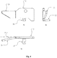
- Figure 4a is a front view of the locking tongue piece 2
- Figure 4b is a side view of the locking tongue piece 2
- Figure 4c is a top view of the locking tongue piece 2.
- the locking tongue piece 2 may be a hard sheet, and the locking tongue piece 2 is provided with a front-end extending portion 21 at its front end.
- the front-end extending portion 21 of the locking tongue piece 2 is arranged at a small angle ⁇ with respect to a main body of the locking tongue piece 2, thus, after the locking tongue piece 2 and the locking piece 11 are movably connected via a pin shaft 8, an angle ⁇ is also formed between the front-end extending portion 21 and the inclined protruding portion 111, and thus the front-end extending portion 21 and the inclined protruding portion 111 will not interfere with each other when the front-end extending portion 21 and the inclined protruding portion 111 respectively engage with the connecting component 7a, and the specific operation process will be described hereinafter.
- the locking tongue piece 2 may further include a spring hooking position 22, and the spring hooking position 22 is arranged at a side surface of the locking tongue piece 2, and is fixedly connected to the tension spring 3.
- Figure 5a is a top view of the base 5
- Figure 5b is a front view of the base 5.
- the base 5 may be a flat plate, and the material of the base 5 and the position for fixing the base 5 may be adjusted according to practical situations, which are not limited specifically.
- the base 5 is provided with at least two mounting holes or at least two protruding shafts 51.
- the guide shafts 6 are embodied as the protruding shafts 51
- at least two protruding shafts 51 are provided on the base 5; and in the case that the guide shafts 6 are embodied as bolts, at least two mounting holes are provided in the base 5.
- the base 5 may be further provided with two mounting holes 52, and in the case that the tension side wall 4 is fixed to the base 5 via screws, the mounting holes 52 are configured to cooperate with the screws to fix the tension side wall 4 to the base 5.
- Figure 5 shows a front view and a top view of the base 5 in the case that the guide shafts 6 are embodied as the protruding shafts 51.
- the connecting component 7a is provided with the groove position 71 and the extending portion 72.
- the groove position 71 is configured to cooperate with the inclined protruding portion 111 of the locking piece 11, and the extending portion 72 is configured to cooperate with the front-end extending portion 21 of the locking tongue piece 2.
- the movement of the connecting component 7a in the vertical direction in Figure 1 may be locked, and the front-end extending portion 21 of the locking tongue piece 2 may be pressed against the bottom of the extending portion 72, as shown in the partially enlarged view in Figure 7 .
- the connecting component 7a and the connecting component 7b may be mounted to the same movable device, and/or, the connecting component 7a and the connecting component 7b may be arranged in the same movable device.
- the connecting component 7a is arranged at a left side of the movable device
- the connecting component 7b is arranged at a right side of the movable device.
- the connecting component 7a and the connecting component 7b may be located on the movable device symmetrically according to the principle of structural mechanics.
- the connection relationship between components of the simple locking device according to this embodiment is described as follows.
- the tension side wall 4 is fixed to the base 5.
- the two guide shafts 6 respectively pass through the two guide holes 12 to mount the locking bracket to the base 5, and the locking bracket 1 is guided by the guide holes 12 to move.
- the tension spring 3 has one end fixed to the tension side wall 4, and another end fixedly connected to the locking bracket 1.
- the locking tongue piece 2 is movably connected to the locking piece 11, and the locking tongue piece 2 is provided with a front-end extending portion 21, and the locking piece 11 is provided with an inclined protruding portion 111.
- the connecting component 7b is provided with a retaining hole 73 configured to cooperate with the retaining piece 13.
- the retaining piece 13 is a wedge-shaped hook.
- the locking bracket 1 may be provided with several retaining pieces 13, and also, the connecting component 7b may be provided with several retaining holes 73 for cooperating with the several retaining pieces 13 respectively.
- the tension side wall 4 is welded to the base 5, or the tension side wall 4 is fixed to the base 5 by a bolt.
- the tension spring 3 is in a tensioned state, and the locking bracket is guided by the guide holes 12 to move by a certain distance in a direction away from the tension side wall 4, the inclined protruding portion 111 of the locking piece 11 is disengaged from the groove position 71 of the connecting component 7a, and the retaining piece 13 is disengaged from the retaining hole 73 of the connecting component 7b.
- the simple locking device has three working states, including an initial state, a locked state, and an unlocked state.
- the tension spring 3 is in an initial state (the tension spring 3 may be in a loose state, and may also be tensioned to a certain extent), and at this time, the locking bracket 1 is at a leftmost end in a movable range under the position-limiting effect of the guide holes 12, and each of the guide shafts 6 is at a rightmost position in the respective guide hole 12.
- the locking bracket 1 is guided by the guide holes 12 to move rightward by a certain distance, at this time, the groove position 71 of the connecting component 7a is just disposed down to the position corresponding to the inclined protruding portion 111, and the retaining hole 73 of the connecting component 7b is just disposed down to a clamping position for engaging with the retaining piece 13.
- the locking bracket 1 moves back leftward by a small distance, to allow the inclined protruding portion 111 to be clamped into the groove position 71, and allow the retaining piece 13 to be clamped into the retaining hole 73 of the connecting component 7b.
- the front-end extending portion 21 of the locking tongue piece 2 continues to be pressed downwards by the extending portion 72 of the connecting component 7a, till the movable device is thoroughly locked into the simple locking device, and at this time, the simple locking device enters into the locked state.
- the locking bracket 1 moves leftward under the action of the restoring force of the tension spring 3, however at this time, the front-end extending portion 21 of the locking tongue piece 2 just abuts against the side surface of the extending portion 72 of the connecting component 7a, and the side surface of the extending portion 72 supports the locking tongue piece 2 and the locking bracket 1, and restricts the locking bracket 1 from moving leftward, and restricts the inclined protruding portion 111 from being clamped into the groove position 71, and restricts the retaining piece 13 from being retained into the retaining hole 73 again, thereby achieving the functions of unlocking and re-position-limiting and re-positioning of the simple locking device.
- the simple locking device enters into the unlocked state.
- a simple locking device includes a locking bracket 1, a locking tongue piece 2, a tension spring 3, a tension side wall 4, a base 5, at least two guide shafts 6, and a connecting component 7a and a connecting component 7b.
- the locking bracket 1 includes a locking piece 11, at least two guide holes 12 and a retaining piece 13.
- the tension side wall 4 is fixed to the base 5.
- the at least two guide shafts 6 respectively pass through the at least two guide holes 12, to mount the locking bracket to the base 5, and the movement of the locking bracket 1 is guided by the guide holes 12.
- the tension spring 3 has one end fixed to the tension side wall 4, and another end fixedly connect to the locking tongue piece 2.
- the locking tongue piece 2 is movably connected to the locking piece 11.
- the locking tongue piece 2 is provided with a front-end extending portion 21 at its front end
- the locking piece 11 is provided with an inclined protruding portion 111
- the connecting component 7a is provided with a groove position 71 configured to cooperate with the inclined protruding portion 111 of the locking piece 11, and an extending portion 72 configured to cooperate with the front-end extending portion 21 of the locking tongue piece 2.
- the connecting component 7b is provided with a retaining hole 73 configured to cooperate with the retaining piece 13.
- the locking bracket 1, the locking tongue piece 2, the tension spring 3, the tension side wall 4, the base 5, the at least two guide shafts 6, the connecting component 7a and the connecting component 7b constitute a locking mechanism, which may perform actions in multiple states by a single mechanism, and no longer just performs the mechanical unlocking and locking by a single action, but can lock the movable device connected to the connecting components 7a and 7b in different states, thus, the operation becomes easier and more convenient, and the improvement of the user experience is facilitated.
- the arrangement of the several retaining pieces 13 may further improve the stability of the movable device after being locked.
- the locking bracket 1 With the handle position 14, the locking bracket 1 may be pulled by a slight action, which facilitates using the locking mechanism.
- the guide shafts 6 are embodied as bolts and the tension side wall 4 is fixed by screws, thus it is easy to disassemble and maintain the simple locking device, and it is also easy to replace the parts.
- the system, the device and the method disclosed herein may be implemented in other manners.
- the embodiments of the device described above are only schematic.
- the division of the units is only a division on logical function, and there may be other division modes in the practical implementation, for instance, multiple units or components may be combined, or may be integrated into another system; and some features may be omitted or unperformed.
- the coupling, direct coupling or communication connection between the components displayed or discussed above may be realized by some interfaces.
- the indirect coupling or communication connection between the devices or units may be electrical, mechanical or other forms.
- the above unit described as a separate component may be or may be not separated physically.
- the component displayed as a unit may be or may be not a physical unit, that is, may be located at one place or may be distributed on multiple network units.
- the object of the solution of the embodiment may be achieved by selecting a part or all of the units according to the practical needs.
- various function units in the embodiments of the present application may be integrated in one processing unit; or, each of the function units may be a single physical presence; or two or more function units are integrated in one unit.
- the above integrated unit may be realized in a form of hardware or in a form of software function unit.
- the integrated unit is implemented in the form of software functional unit and is sold or used as a separate product, it can also be stored in a computer readable storage medium.
- the computer software product is stored in a storage medium, and includes several instructions which enables a computer device (which may be a personal computer, a server, or a network device, and etc.) to execute all or part of the step of the method of each embodiment of the present application.
- the storage medium described above includes various medium capable of storing program codes, such as a USB mass storage device, a movable storage device, a Read-Only Memory (ROM), a Random Access Memory (RAM), a magnetic disc or an optical disc.
Abstract
Description
- This application claims the benefit of priority to Chinese Patent Application No.
CN201410188640.X - The present application relates to the field of mechanical apparatus, and particularly to a simple locking device.
- With the development and progress of the society, movable devices play an extremely important role in people's daily life, and people's dependency upon the movable devices has been increasingly high. In many occasions, people need to position and lock the movable devices.
- In the conventional locking devices, for locking the movable device, generally, multiple locking components (such as a handle catch, a rotary lock or a movable pin lock), each having a single capability, are adopted to lock the movable device.
- However, generally, this kind of locking device can only achieve mechanical unlocking and locking by a single action, or achieve one function by multiple mechanisms and/or multiple actions, and cannot perform actions in multiple states by a single mechanism to achieve the locking function in various states, therefore, the operation is troublesome.
- A simple locking device is provided according to the present application, which can perform actions in multiple states by a single mechanism to lock up a movable device, thereby making the operation to be easier and more convenient and facilitating improving the user experience.
- A simple locking device according to embodiments of the present application, includes a locking bracket, a locking tongue piece, a tension spring, a tension side wall, a base, at least two guide shafts, a connecting
component 7a and a connectingcomponent 7b. The locking bracket includes a locking piece, at least two guide holes and a retaining piece. The tension side wall is fixed to the base. The at least two guide shafts respectively pass through the at least two guide holes to mount the locking bracket to the base, and the locking bracket configured to be guided by the guide holes to move. The tension spring has one end fixed to the tension side wall, and another end fixedly connected to the locking tongue piece. The locking tongue piece is movably connected to the locking piece, the locking tongue piece is provided with a front-end extending portion, and the locking piece is provided with an inclined protruding portion. The connectingcomponent 7a is provided with a groove position configured to cooperate with the inclined protruding portion of the locking piece, and an extending portion configured to cooperate with the front-end extending portion of the locking tongue piece. The connectingcomponent 7b is provided with a retaining hole configured to cooperate with the retaining piece. - Optionally, the locking tongue piece further includes a spring hooking position, and the spring hooking position is arranged at a side surface of the locking tongue piece, and is fixedly connected to the tension spring; and the locking bracket further includes a handle position, and the handle position is arranged at an end of the locking bracket close to the retaining piece, and is configured to provide a force applying point for pulling the locking bracket.
- Optionally, the connecting
component 7a and the connectingcomponent 7b are configured to be mounted to a same movable device; and/or, the connectingcomponent 7a and the connectingcomponent 7b are configured to be arranged on a same movable device. - Optionally, the connecting
component 7a and the connectingcomponent 7b are respectively configured to be located on the movable device symmetrically. - Optionally, the simple locking device further includes a pin shaft, and the pin shaft is configured to allow the locking tongue piece to be movably connected to the locking piece.
- Optionally, in the case that the inclined protruding portion of the locking piece is clamped into the groove position of the connecting
component 7a, the extending portion of the connectingcomponent 7a presses the front end protrusion of the locking tongue piece downwards and abuts against the front end protrusion of the locking tongue piece, and the retaining piece is retained into the retaining hole of the connectingcomponent 7b. - Optionally, in the case that the front-end extending portion of the locking tongue piece abuts against a side surface of the extending portion of the connecting
component 7a, the tension spring is in a tensioned state, and the locking bracket is guided by the guide holes to move by a certain distance in a direction away from the tension side wall, and the inclined protruding portion of the locking piece is disengaged from the groove position of the connectingcomponent 7a, and the retaining piece is disengaged from the retaining hole of the connectingcomponent 7b. - Optionally, the guide holes have the same guide directions.
- Optionally, the guide shafts are bolts; or, the guide shafts are protruding shafts arranged on the base.
- Optionally, the tension side wall is welded to the base; or, the tension side wall is fixed to the base by a bolt.
- As described in the above technical solutions, the present application has the following advantages.
- In the present application, a simple locking device includes a locking bracket, a locking tongue piece, a tension spring, a tension side wall, a base, at least two guide shafts, and a connecting
component 7a and a connectingcomponent 7b. The locking bracket includes a locking piece, at least two guide holes and a retaining piece. The tension side wall is fixed to the base. The at least two guide shafts respectively pass through the at least two guide holes, to mount the locking bracket to the base, and the movement of the locking bracket is guided by the guide holes. The tension spring has one end fixed to the tension side wall, and another end fixedly connect to the locking tongue piece. The locking tongue piece is movably connected to the locking piece. The locking tongue piece is provided with a front-end extending portion at its front end, the locking piece is provided with an inclined protruding portion, and the connectingcomponent 7a is provided with a groove position configured to cooperate with the inclined protruding portion of the locking piece, and an extending portion configured to cooperate with the front-end extending portion of the locking tongue piece. The connectingcomponent 7b is provided with a retaining hole configured to cooperate with the retaining piece. In this embodiment of the present application, the locking bracket, the locking tongue piece, the tension spring, the tension side wall, the base, the at least two guide shafts, the connectingcomponent 7a and the connectingcomponent 7b constitute a locking mechanism, which may perform actions in multiple states by a single mechanism, and no longer just performs the mechanical unlocking and locking by a single action, but can lock the movable device connected to the connectingcomponent 7a and the connecting component7b in different states, thus, the operation becomes easier and more convenient, and the improvement of the user experience is facilitated. -
-
Figure 1 is a schematic view showing the structure of an embodiment of a simple locking device according to the present application; -
Figure 2 is a schematic view showing the structure of a locking bracket according to the present application, wherein,Figure 2a is a top view of the locking bracket, andFigure 2b is a front view of the locking bracket; -
Figure 3 is a schematic view showing the structure of the simple locking device according to the embodiment of the present application, with a movable device being locked to the simple locking device, wherein,Figure 3a is a top view of the simple locking device,Figure 3b is a right view of the simple locking device,Figure 3c is a front view of the simple locking device, andFigure 3d is a left view of the simple locking device; -
Figure 4 is a schematic view showing the structure of a locking tongue piece according to the embodiment of the present application, wherein,Figure 4a is a front view of the locking tongue piece,Figure 4b is a side view of the locking tongue piece, andFigure 4c is a top view of the locking tongue piece; -
Figure 5 is a schematic view showing the structure of a base according to the embodiment of the present application, wherein,Figure 5a is a top view of thebase 5, andFigure 5b is a front view of thebase 5; -
Figure 6 is a schematic view showing the structure of a connectingcomponent 7a according to the present application; -
Figure 7 is a partially enlarged view showing the structure of the simple locking device according to the embodiment of the present application, with the movable device being locked to the simple locking device; and -
Figure 8 is schematic view showing the structure of a simple locking device being operated to switch between an initial state, a locked state, and an unlocked state, according to the embodiment of the present application, wherein,Figure 8a shows the simple locking device in the initial state,Figure 8b shows the simple locking device in the locked state, andFigure 8c shows the simple locking device in the unlocked state. - A simple locking device is provided according to an embodiment of the present application, which is configured to perform actions in multiple states by a single mechanism to lock the movable device, thereby making the operation to be easier and more convenient, and facilitating improving the user experience.
- For making the objects, features and advantages of the present application clearer and easier to be understood, the technical solutions according to the present application are described clearly and completely hereinafter in conjunction with the drawings in the embodiments of the present application. Apparently, the embodiments described hereinafter are only a part of the embodiments of the present application, rather than all embodiments. Based on the embodiments in the present application, all of other embodiments, made by the person skilled in the art without any creative efforts, fall into the scope of the present application.
- Referring to
Figures 1 to 8 , an embodiment of a simple locking device according to the present application includes alocking bracket 1, alocking tongue piece 2, atension spring 3, atension side wall 4, abase 5, at least twoguide shafts 6, a connectingcomponent 7a and a connectingcomponent 7b, as shown inFigure 1 . - Reference is made to
Figure 2, Figure 2a is a top view of thelocking bracket 1, andFigure 2b is a front view of thelocking bracket 1. Thelocking bracket 1 includes alocking piece 11, at least twoguide holes 12, and aretaining piece 13. Theguide holes 12 have the same guide directions. The structure of thelocking piece 11 may be referred toFigure 2 . As illustrated inFigure 2 , thelocking piece 11 may be a hard sheet perpendicular to a plane where theguide holes 12 are located, and a front end of thelocking piece 11 is provided with aninclined protruding portion 111, and theinclined protruding portion 111 may cooperate with agroove position 71 of the connectingcomponent 7a to achieve the locking function. The specific operation process is described hereinafter. As illustrated inFigure 2 , thelocking piece 11 is arranged at a left end of thelocking bracket 1, theretaining piece 13 is arranged at a right end of thelocking bracket 1, and theretaining piece 13 can be retained in aretaining hole 73 in the connectingcomponent 7b, to lock the connectingcomponent 7b. Thelocking bracket 1 may further be provided with ahandle position 14, and thehandle position 14 is arranged at an end, close to theretaining piece 13, of thelocking bracket 1, and is configured to provide a force applying point for pulling thelocking bracket 1. -
Figure 3 is a schematic view showing the structure of the simple locking device according to the embodiment of the present application, with a movable device being locked to the simple locking device, wherein,Figure 3a is a top view of the simple locking device,Figure 3b is a right view of the simple locking device,Figure 3c is a front view of the simple locking device, andFigure 3d is a left view of the simple locking device. - Reference is made to
Figure 4, Figure 4a is a front view of thelocking tongue piece 2,Figure 4b is a side view of thelocking tongue piece 2, andFigure 4c is a top view of thelocking tongue piece 2. Thelocking tongue piece 2 may be a hard sheet, and thelocking tongue piece 2 is provided with a front-end extending portion 21 at its front end. For better cooperating with an extendingportion 72 of the connectingcomponent 7a, the front-end extending portion 21 of thelocking tongue piece 2 is arranged at a small angle θ with respect to a main body of thelocking tongue piece 2, thus, after thelocking tongue piece 2 and thelocking piece 11 are movably connected via apin shaft 8, an angle θ is also formed between the front-end extending portion 21 and theinclined protruding portion 111, and thus the front-end extending portion 21 and theinclined protruding portion 111 will not interfere with each other when the front-end extending portion 21 and theinclined protruding portion 111 respectively engage with the connectingcomponent 7a, and the specific operation process will be described hereinafter. The lockingtongue piece 2 may further include aspring hooking position 22, and thespring hooking position 22 is arranged at a side surface of the lockingtongue piece 2, and is fixedly connected to thetension spring 3. - Reference is made to
Figure 5, Figure 5a is a top view of thebase 5, andFigure 5b is a front view of thebase 5. Thebase 5 may be a flat plate, and the material of thebase 5 and the position for fixing thebase 5 may be adjusted according to practical situations, which are not limited specifically. Thebase 5 is provided with at least two mounting holes or at least two protrudingshafts 51. In the case that theguide shafts 6 are embodied as the protrudingshafts 51, at least two protrudingshafts 51 are provided on thebase 5; and in the case that theguide shafts 6 are embodied as bolts, at least two mounting holes are provided in thebase 5. Thebase 5 may be further provided with two mountingholes 52, and in the case that thetension side wall 4 is fixed to thebase 5 via screws, the mountingholes 52 are configured to cooperate with the screws to fix thetension side wall 4 to thebase 5.Figure 5 shows a front view and a top view of thebase 5 in the case that theguide shafts 6 are embodied as the protrudingshafts 51. - Referring to
Figure 6 , the connectingcomponent 7a is provided with thegroove position 71 and the extendingportion 72. Thegroove position 71 is configured to cooperate with the inclined protrudingportion 111 of the lockingpiece 11, and the extendingportion 72 is configured to cooperate with the front-end extending portion 21 of the lockingtongue piece 2. After the inclined protrudingportion 111 is retained into thegroove position 71, the movement of the connectingcomponent 7a in the vertical direction inFigure 1 may be locked, and the front-end extending portion 21 of the lockingtongue piece 2 may be pressed against the bottom of the extendingportion 72, as shown in the partially enlarged view inFigure 7 . - Referring to
Figure 7 , the connectingcomponent 7a and the connectingcomponent 7b may be mounted to the same movable device, and/or, the connectingcomponent 7a and the connectingcomponent 7b may be arranged in the same movable device. InFigure 7 , the connectingcomponent 7a is arranged at a left side of the movable device, and the connectingcomponent 7b is arranged at a right side of the movable device. As illustrated inFigure 7 , the connectingcomponent 7a and the connectingcomponent 7b may be located on the movable device symmetrically according to the principle of structural mechanics. - The connection relationship between components of the simple locking device according to this embodiment is described as follows. The
tension side wall 4 is fixed to thebase 5. - Preferably, the two
guide shafts 6 respectively pass through the twoguide holes 12 to mount the locking bracket to thebase 5, and thelocking bracket 1 is guided by the guide holes 12 to move. - The
tension spring 3 has one end fixed to thetension side wall 4, and another end fixedly connected to thelocking bracket 1. - The locking
tongue piece 2 is movably connected to thelocking piece 11, and the lockingtongue piece 2 is provided with a front-end extending portion 21, and thelocking piece 11 is provided with an inclined protrudingportion 111. - The connecting
component 7b is provided with a retaininghole 73 configured to cooperate with the retainingpiece 13. - Preferably, the retaining
piece 13 is a wedge-shaped hook. The lockingbracket 1 may be provided with several retainingpieces 13, and also, the connectingcomponent 7b may be provided with several retainingholes 73 for cooperating with the several retainingpieces 13 respectively. - Preferably, the
tension side wall 4 is welded to thebase 5, or thetension side wall 4 is fixed to thebase 5 by a bolt. - In the case that the front-
end extending portion 21 of the lockingtongue piece 2 abuts against a side surface of the extendingportion 72 of the connectingcomponent 7a, thetension spring 3 is in a tensioned state, and the locking bracket is guided by the guide holes 12 to move by a certain distance in a direction away from thetension side wall 4, the inclined protrudingportion 111 of the lockingpiece 11 is disengaged from thegroove position 71 of the connectingcomponent 7a, and the retainingpiece 13 is disengaged from the retaininghole 73 of the connectingcomponent 7b. - The working process of an embodiment of the simple locking device is described in detail hereinafter.
- The simple locking device has three working states, including an initial state, a locked state, and an unlocked state.
- In the initial state, referring to
Figure 8a , the movable device is not laid down, at this time, thetension spring 3 is in an initial state (thetension spring 3 may be in a loose state, and may also be tensioned to a certain extent), and at this time, the lockingbracket 1 is at a leftmost end in a movable range under the position-limiting effect of the guide holes 12, and each of theguide shafts 6 is at a rightmost position in therespective guide hole 12. - In the locked state, referring to
Figure 8b , the movable device has been locked by the simple locking device, the inclined protrudingportion 111 of the lockingpiece 11 is clamped into thegroove position 71 of the connectingcomponent 7a at the left side of the movable device, and the front-end extending portion 21 of the lockingtongue piece 2 is pressed against the bottom of the extendingportion 72 of the connectingcomponent 7a, thetension spring 3 is in a tensioned state (a force accumulating state), and thelocking bracket 1 moves rightward by a certain distance under the position-limiting effect of the guide holes 12, and each of theguide shafts 6 is at a position, close to the left end of therespective guide hole 12, in the respective guide hole 12 (each of theguide shafts 6 may be at a leftmost end of therespective guide hole 12, and may also be spaced from the leftmost end of therespective guide hole 12 by a certain distance). The retainingpiece 13 is clamped in the retaininghole 73 of the connectingcomponent 7b at the right side of the movable device. - In the unlocked state, referring to
Figure 8c , the front-end extending portion 21 of the lockingtongue piece 2 abuts against the side surface of the connectingcomponent 7a, and the lockingtongue piece 2 rotates upwards by a certain angle, and thetension spring 3 is in a tensioned state, the inclined protrudingportion 111 of the lockingpiece 11 is disengaged from thegroove position 71 of the connectingcomponent 7a, and the retainingpiece 13 is also disengaged from the retaininghole 73 of the connectingcomponent 7b. The movable device is in an unlocked state in the vertical direction, and may be drawn out in the vertical direction. - In the process of switching from the initial state to the locked state, referring to
Figure 8 , in the case that the movable device is laid down, the extendingportion 72 of the connectingcomponent 7a presses the front-end extending portion 21 of the lockingtongue piece 2 downwards, and the connectingcomponent 7a presses an upper portion of the inclined protrudingportion 111 of the lockingpiece 11 downwards, and the connectingcomponent 7b presses an upper portion of the retainingpiece 13 downwards, to allow each of the lockingtongue piece 2, the lockingbracket 1 and the retainingpiece 13 to overcome the tensioning force of thetension spring 3 to generate an action force for moving rightwards. The lockingbracket 1 is guided by the guide holes 12 to move rightward by a certain distance, at this time, thegroove position 71 of the connectingcomponent 7a is just disposed down to the position corresponding to the inclined protrudingportion 111, and the retaininghole 73 of the connectingcomponent 7b is just disposed down to a clamping position for engaging with the retainingpiece 13. At this time, under the effect of the tensioning force (the restoring force) of thetension spring 3, the lockingbracket 1 moves back leftward by a small distance, to allow the inclined protrudingportion 111 to be clamped into thegroove position 71, and allow the retainingpiece 13 to be clamped into the retaininghole 73 of the connectingcomponent 7b. The front-end extending portion 21 of the lockingtongue piece 2 continues to be pressed downwards by the extendingportion 72 of the connectingcomponent 7a, till the movable device is thoroughly locked into the simple locking device, and at this time, the simple locking device enters into the locked state. - In the process of switching from the locked state to the unlocked state, referring to
Figure 8 , if the movable device is required to be drawn out, thehandle position 14 is pulled slightly, and thelocking bracket 1 moves rightward by a certain distance under the action of the pulling force, and at this time, the lockingtongue piece 2 is turned upward by a certain angle about thepin shaft 8 under the pulling force of the tension spring 3 (the angle may be determined by a preset structure of the locking tongue piece 2), and the inclined protrudingportion 111 is disengaged from thegroove position 71 of the connecting component a, and the retainingpiece 13 is disengaged from the retaininghole 73. After thehandle position 14 is released, the lockingbracket 1 moves leftward under the action of the restoring force of thetension spring 3, however at this time, the front-end extending portion 21 of the lockingtongue piece 2 just abuts against the side surface of the extendingportion 72 of the connectingcomponent 7a, and the side surface of the extendingportion 72 supports the lockingtongue piece 2 and thelocking bracket 1, and restricts thelocking bracket 1 from moving leftward, and restricts the inclined protrudingportion 111 from being clamped into thegroove position 71, and restricts the retainingpiece 13 from being retained into the retaininghole 73 again, thereby achieving the functions of unlocking and re-position-limiting and re-positioning of the simple locking device. The simple locking device enters into the unlocked state. - In the process of switching from the unlocked state to the initial state, referring to
Figure 8 , the movable device is drawn out in the vertical direction. In the process of drawing out the movable device, the lockingtongue piece 2 is no longer supported by the side surface of the extendingportion 72 of the connectingcomponent 7a, thus the lockingtongue piece 2 and thelocking bracket 1 move leftward under the effect of the tensioning force of thetension spring 3, till the simple locking device is recovered to the initial state. - In this embodiment, a simple locking device includes a
locking bracket 1, a lockingtongue piece 2, atension spring 3, atension side wall 4, abase 5, at least twoguide shafts 6, and a connectingcomponent 7a and a connectingcomponent 7b. The lockingbracket 1 includes alocking piece 11, at least twoguide holes 12 and a retainingpiece 13. Thetension side wall 4 is fixed to thebase 5. The at least twoguide shafts 6 respectively pass through the at least twoguide holes 12, to mount the locking bracket to thebase 5, and the movement of thelocking bracket 1 is guided by the guide holes 12. Thetension spring 3 has one end fixed to thetension side wall 4, and another end fixedly connect to the lockingtongue piece 2. The lockingtongue piece 2 is movably connected to thelocking piece 11. The lockingtongue piece 2 is provided with a front-end extending portion 21 at its front end, the lockingpiece 11 is provided with an inclined protrudingportion 111, and the connectingcomponent 7a is provided with agroove position 71 configured to cooperate with the inclined protrudingportion 111 of the lockingpiece 11, and an extendingportion 72 configured to cooperate with the front-end extending portion 21 of the lockingtongue piece 2. The connectingcomponent 7b is provided with a retaininghole 73 configured to cooperate with the retainingpiece 13. In this embodiment, the lockingbracket 1, the lockingtongue piece 2, thetension spring 3, thetension side wall 4, thebase 5, the at least twoguide shafts 6, the connectingcomponent 7a and the connectingcomponent 7b constitute a locking mechanism, which may perform actions in multiple states by a single mechanism, and no longer just performs the mechanical unlocking and locking by a single action, but can lock the movable device connected to the connectingcomponents pieces 13 may further improve the stability of the movable device after being locked. With thehandle position 14, the lockingbracket 1 may be pulled by a slight action, which facilitates using the locking mechanism. Theguide shafts 6 are embodied as bolts and thetension side wall 4 is fixed by screws, thus it is easy to disassemble and maintain the simple locking device, and it is also easy to replace the parts. - The person skilled in the art may clearly know that, for convenience and brevity of the description, the specific working process of the system, device, and unit described above may refer to the corresponding process in the embodiment of the method described above, which are not described herein further.
- In the several embodiments provided by the present application, it should be appreciated that, the system, the device and the method disclosed herein may be implemented in other manners. For example, the embodiments of the device described above are only schematic. For example, the division of the units is only a division on logical function, and there may be other division modes in the practical implementation, for instance, multiple units or components may be combined, or may be integrated into another system; and some features may be omitted or unperformed. In addition, the coupling, direct coupling or communication connection between the components displayed or discussed above may be realized by some interfaces. The indirect coupling or communication connection between the devices or units may be electrical, mechanical or other forms.
- The above unit described as a separate component may be or may be not separated physically. The component displayed as a unit may be or may be not a physical unit, that is, may be located at one place or may be distributed on multiple network units. The object of the solution of the embodiment may be achieved by selecting a part or all of the units according to the practical needs.
- Furthermore, various function units in the embodiments of the present application may be integrated in one processing unit; or, each of the function units may be a single physical presence; or two or more function units are integrated in one unit. The above integrated unit may be realized in a form of hardware or in a form of software function unit.
- In the case that the integrated unit is implemented in the form of software functional unit and is sold or used as a separate product, it can also be stored in a computer readable storage medium. Based on such understanding, the essence or the part that contributes to the conventional technology of the technical solutions of the present application or a part or whole of the technical solutions may be expressed in the form of a software product. The computer software product is stored in a storage medium, and includes several instructions which enables a computer device (which may be a personal computer, a server, or a network device, and etc.) to execute all or part of the step of the method of each embodiment of the present application. The storage medium described above includes various medium capable of storing program codes, such as a USB mass storage device, a movable storage device, a Read-Only Memory (ROM), a Random Access Memory (RAM), a magnetic disc or an optical disc.
- The above description and the above embodiments only intend to illustrate the technical solutions of the present application, and are not deemed to limit the present application. Though the present application has been described in detail with reference to the above embodiments, it should be understood by the person skilled in the art that, they may still make modifications to the technical solutions set forth in the various embodiments described above, or make equivalent substitution to partial of the technical features in the above embodiments; and all these modifications or substitutions do not make the essence of the respective technical solutions depart from the spirit and scope of the technical solutions of the embodiments of the present application.
Claims (10)
- A simple locking device, comprising:a locking bracket (1), a locking tongue piece (2), a tension spring (3), a tension side wall (4), a base (5), at least two guide shafts (6), a connecting component (7a) and a connecting component (7b); wherein,the locking bracket (1) comprises a locking piece (11), at least two guide holes (12) and a retaining piece (13);the tension side wall (4) is fixed to the base (5);the at least two guide shafts (6) respectively pass through the at least two guide holes (12) to mount the locking bracket to the base (5), and the locking bracket (1) is configured to be guided by the guide holes (12) to move;the tension spring (3) has one end fixed to the tension side wall (4), and another end fixedly connected to the locking tongue piece (2);the locking tongue piece (2) is movably connected to the locking piece (11), the locking tongue piece (2) is provided with a front-end extending portion (21), and the locking piece (11) is provided with an inclined protruding portion (111);the connecting component (7a) is provided with a groove position (71) configured to cooperate with the inclined protruding portion (111) of the locking piece (11), and an extending portion (72) configured to cooperate with the front-end extending portion (21) of the locking tongue piece (2); andthe connecting component (7b) is provided with a retaining hole (73) configured to cooperate with the retaining piece (13).
- The simple locking device according to claim 1, wherein the locking tongue piece (2) further comprises a spring hooking position (22);
the spring hooking position (22) is arranged at a surface side of the locking tongue piece (2), and is fixedly connected to the tension spring (3);
the locking bracket (1) further comprises a handle position (14); and
the handle position (14) is arranged at an end of the locking bracket (1) close to the retaining piece (13), and is configured to provide a force applying point for pulling the locking bracket (1). - The simple locking device according to claim 1, wherein
the connecting component (7a) and the connecting component (7b) are configured to be mounted to a same movable device;
and/or,
the connecting component (7a) and the connecting component (7b) are configured to be arranged on a same movable device. - The simple locking device according to claim 3, wherein
the connecting component (7a) and the connecting component (7b) are respectively configured to be located on the movable device symmetrically. - The simple locking device according to claim 1, further comprising a pin shaft (8); wherein the pin shaft (8) is configured to allow the locking tongue piece (2) to be movably connected to the locking piece (11).
- The simple locking device according to claim 1, wherein
in the case that the inclined protruding portion (111) of the locking piece (11) is clamped into the groove position (71) of the connecting component (7a), the extending portion (72) of the connecting component (7a) presses the front end protrusion (21) of the locking tongue piece (2) downwards and abuts against the front end protrusion (21) of the locking tongue piece (2), and the retaining piece (13) is retained into the retaining hole (73) of the connecting component (7b). - The simple locking device according to claim 1, wherein,
in the case that the front-end extending portion (21) of the locking tongue piece (2) abuts against a side surface of the extending portion (72) of the connecting component (7a), the tension spring (3) is in a tensioned state, and the locking bracket is guided by the guide holes (12) to move by a certain distance in a direction away from the tension side wall (4), and the inclined protruding portion (111) of the locking piece (11) is disengaged from the groove position (71) of the connecting component (7a), and the retaining piece (13) is disengaged from the retaining hole (73) of the connecting component (7b). - The simple locking device according to claim 1, wherein
the guide holes (12) have the same guide directions. - The simple locking device according to any one of claims 1 to 8, wherein,
the guide shafts (6) are bolts;
or,
the guide shafts (6) are protruding shafts arranged on the base seat (5). - The simple locking device according to any one of claims 1 to 8, wherein
the tension side wall (4) is welded to the base (5);
or,
the tension side wall (4) is fixed to the base (5) by a bolt.
Applications Claiming Priority (2)
| Application Number | Priority Date | Filing Date | Title |
|---|---|---|---|
| CN201410188640.XA CN103939431B (en) | 2014-05-06 | 2014-05-06 | A kind of Simple lock |
| PCT/CN2014/089558 WO2015169065A1 (en) | 2014-05-06 | 2014-10-27 | Simple locking device |
Publications (3)
| Publication Number | Publication Date |
|---|---|
| EP3141765A1 true EP3141765A1 (en) | 2017-03-15 |
| EP3141765A4 EP3141765A4 (en) | 2017-03-29 |
| EP3141765B1 EP3141765B1 (en) | 2018-05-02 |
Family
ID=51187256
Family Applications (1)
| Application Number | Title | Priority Date | Filing Date |
|---|---|---|---|
| EP14891430.2A Not-in-force EP3141765B1 (en) | 2014-05-06 | 2014-10-27 | Simple locking device |
Country Status (6)
| Country | Link |
|---|---|
| US (1) | US9903399B2 (en) |
| EP (1) | EP3141765B1 (en) |
| CN (1) | CN103939431B (en) |
| AU (1) | AU2014393109B2 (en) |
| CL (1) | CL2016001483A1 (en) |
| WO (1) | WO2015169065A1 (en) |
Cited By (2)
| Publication number | Priority date | Publication date | Assignee | Title |
|---|---|---|---|---|
| CN110345358A (en) * | 2019-08-19 | 2019-10-18 | 深圳市领灿科技有限公司 | Self-locking mechanism is safeguarded before a kind of LED display mould group |
| CN113757229A (en) * | 2020-06-03 | 2021-12-07 | 鸿富锦精密电子(天津)有限公司 | Rotary buckle and fixing device |
Families Citing this family (9)
| Publication number | Priority date | Publication date | Assignee | Title |
|---|---|---|---|---|
| CN103939431B (en) * | 2014-05-06 | 2016-01-20 | 广州广电运通金融电子股份有限公司 | A kind of Simple lock |
| CN108071631A (en) * | 2018-01-29 | 2018-05-25 | 西门子数控(南京)有限公司 | Snap close piece, interlocking assembly and docking platform |
| TWI764164B (en) * | 2020-06-03 | 2022-05-11 | 新加坡商鴻運科股份有限公司 | Rotating buckle and fixing device |
| TWI762944B (en) * | 2020-06-04 | 2022-05-01 | 大陸商光寶電子(廣州)有限公司 | Fastener structure |
| CN111765151B (en) * | 2020-06-12 | 2022-03-15 | 中国船舶重工集团公司第七二四研究所 | Plug-in power assisting device with locking function |
| TWI816117B (en) * | 2021-05-08 | 2023-09-21 | 新加坡商鴻運科股份有限公司 | Function module lock device and function module |
| CN114233981B (en) * | 2021-12-08 | 2023-02-24 | 珠海格力电器股份有限公司 | Footing subassembly, compressor and air conditioner |
| CN115013389B (en) * | 2022-05-30 | 2023-03-10 | 武汉理工大学 | Locking mechanism with adjustable displacement compensation function |
| CN114918968B (en) * | 2022-06-28 | 2023-04-25 | 南京信息工程大学 | Butt joint device |
Citations (3)
| Publication number | Priority date | Publication date | Assignee | Title |
|---|---|---|---|---|
| GB1154671A (en) * | 1967-01-17 | 1969-06-11 | Jack Maurice Hall | Improvements relating to Strong Boxes. |
| US3773252A (en) * | 1971-07-02 | 1973-11-20 | Seeburg Corp | Self-locking cash box |
| DE8815810U1 (en) * | 1988-12-21 | 1989-02-23 | Seeger, Edgar, 3501 Niestetal, De |
Family Cites Families (39)
| Publication number | Priority date | Publication date | Assignee | Title |
|---|---|---|---|---|
| US1626A (en) * | 1840-06-10 | Spring-bolt for door and other locks | ||
| US58548A (en) * | 1866-10-02 | Improved lock for trunks | ||
| US1037662A (en) * | 1911-10-23 | 1912-09-03 | George B Roberts | Window-lock. |
| US1192105A (en) * | 1916-03-22 | 1916-07-25 | Fritz Bohle | Latch. |
| US1349032A (en) * | 1919-02-17 | 1920-08-10 | Windsor Cecil Stanley | Self-locking pivoted joint |
| GB300617A (en) * | 1927-11-16 | 1930-02-17 | Guy De Bonal | Improved automatic locking or braking apparatus |
| US1987076A (en) * | 1934-01-23 | 1935-01-08 | Oscar B Pulis | Latch for panels |
| US2698762A (en) * | 1950-11-22 | 1955-01-04 | Houdaille Hershey Corp | Latch release mechanism |
| US4174508A (en) * | 1978-05-10 | 1979-11-13 | Westinghouse Air Brake Company | Relay latching apparatus |
| DE2912881A1 (en) * | 1979-03-30 | 1980-10-09 | Scovill Sicherheitseinrichtung | Two winged fire screen door drive bar lock - has auxiliary latch head axially adjustable on latch shaft |
| JPH0431147Y2 (en) * | 1987-01-23 | 1992-07-27 | ||
| US5113676A (en) * | 1990-12-31 | 1992-05-19 | Misak Panossian | Double acting dead latch mechanism |
| DE19507712C1 (en) * | 1995-03-07 | 1996-04-04 | Schroff Gmbh | Insertion and retraction device for plug-in circuit module |
| US6688656B1 (en) * | 1999-11-22 | 2004-02-10 | Truth Hardware Corporation | Multi-point lock |
| US6820905B1 (en) * | 2000-07-26 | 2004-11-23 | Detex Corporation | Vertical panic exit device |
| US6556450B1 (en) * | 2002-04-08 | 2003-04-29 | Wms Gaming Inc. | Methods and apparatus of docking a gaming control board to an interface board in a gaming machine |
| JP2004343061A (en) * | 2003-03-24 | 2004-12-02 | Schroff Gmbh | Plug-in module for insertion and extraction from module frame |
| US6967847B2 (en) * | 2003-06-11 | 2005-11-22 | Hewlett-Packard Development Company, L.P. | Computer system with movable card guide |
| JP2005069452A (en) * | 2003-08-28 | 2005-03-17 | Tsutomu Tatsumoto | Locking mechanism with locking position adjusting function |
| US7027309B2 (en) * | 2004-02-20 | 2006-04-11 | Hewlett-Packard Development Company, L.P. | Engaging/disengaging mechanism |
| US7292457B2 (en) * | 2005-03-31 | 2007-11-06 | Intel Corporation | Folding latching mechanism |
| CN101012711B (en) * | 2006-01-16 | 2010-05-12 | 广州广电运通金融电子股份有限公司 | Magnetic lock and money box using the same |
| JP4820258B2 (en) * | 2006-09-29 | 2011-11-24 | 本田技研工業株式会社 | Article storage structure for small boats |
| US8342580B2 (en) * | 2006-11-09 | 2013-01-01 | Apex Brands, Inc. | Lock system for a container |
| US8226131B1 (en) * | 2007-09-04 | 2012-07-24 | Augmentix Corporation | System, method and apparatus for door latching using a spring latch |
| US7712799B2 (en) * | 2007-12-03 | 2010-05-11 | Fu Chang Locks Mfg Corp. | Hidden lock locked to an inner side of a doorplate |
| CN201162743Y (en) * | 2008-02-04 | 2008-12-10 | 正凌精密工业股份有限公司 | Handle locking structure |
| CN201277224Y (en) | 2008-06-17 | 2009-07-22 | 长沙申大科技有限公司 | Interlock mechanism |
| US8077473B1 (en) * | 2008-08-28 | 2011-12-13 | Force10 Networks, Inc. | Spring-latching circuit module injector/ejector |
| CA2681067C (en) * | 2008-10-03 | 2015-04-14 | Truth Hardware Corporation | Sliding door multipoint mortise lock with shoot bolts |
| CN102287424B (en) * | 2010-06-21 | 2013-04-17 | 北汽福田汽车股份有限公司 | Lock-up mechanism |
| US8353549B2 (en) * | 2011-04-18 | 2013-01-15 | Honda Motor Co., Ltd. | Push button mechanism for opening and closing a storage compartment for a vehicle |
| CN102444649A (en) * | 2011-09-19 | 2012-05-09 | 满孝臣 | Improved frame structure |
| CN102536976B (en) * | 2011-12-31 | 2013-11-20 | 深圳市通普科技有限公司 | Locking device |
| CN103511408A (en) * | 2012-06-21 | 2014-01-15 | 海洋王照明科技股份有限公司 | Shell body locking structure and lamp |
| CN103149981B (en) * | 2013-02-27 | 2016-06-01 | 联宝(合肥)电子科技有限公司 | A kind of can the buckle structure of singlehanded folding and method of work thereof |
| US8976536B2 (en) * | 2013-04-10 | 2015-03-10 | Lenovo Enterprise Solutions (Singapore) Pte. Ltd. | Latching cam handle assembly for securing mated circuit boards |
| CN103939431B (en) * | 2014-05-06 | 2016-01-20 | 广州广电运通金融电子股份有限公司 | A kind of Simple lock |
| DE102016113809A1 (en) | 2016-07-27 | 2018-02-01 | DEHN + SÖHNE GmbH + Co. KG. | Fastening device for an electrical component located in a housing |
-
2014
- 2014-05-06 CN CN201410188640.XA patent/CN103939431B/en active Active
- 2014-10-27 WO PCT/CN2014/089558 patent/WO2015169065A1/en active Application Filing
- 2014-10-27 EP EP14891430.2A patent/EP3141765B1/en not_active Not-in-force
- 2014-10-27 AU AU2014393109A patent/AU2014393109B2/en not_active Ceased
- 2014-10-27 US US15/104,392 patent/US9903399B2/en not_active Expired - Fee Related
-
2016
- 2016-06-13 CL CL2016001483A patent/CL2016001483A1/en unknown
Patent Citations (3)
| Publication number | Priority date | Publication date | Assignee | Title |
|---|---|---|---|---|
| GB1154671A (en) * | 1967-01-17 | 1969-06-11 | Jack Maurice Hall | Improvements relating to Strong Boxes. |
| US3773252A (en) * | 1971-07-02 | 1973-11-20 | Seeburg Corp | Self-locking cash box |
| DE8815810U1 (en) * | 1988-12-21 | 1989-02-23 | Seeger, Edgar, 3501 Niestetal, De |
Non-Patent Citations (1)
| Title |
|---|
| See also references of WO2015169065A1 * |
Cited By (4)
| Publication number | Priority date | Publication date | Assignee | Title |
|---|---|---|---|---|
| CN110345358A (en) * | 2019-08-19 | 2019-10-18 | 深圳市领灿科技有限公司 | Self-locking mechanism is safeguarded before a kind of LED display mould group |
| CN110345358B (en) * | 2019-08-19 | 2021-03-26 | 深圳市领灿科技有限公司 | Front maintenance self-locking mechanism of LED display screen module |
| CN113757229A (en) * | 2020-06-03 | 2021-12-07 | 鸿富锦精密电子(天津)有限公司 | Rotary buckle and fixing device |
| CN113757229B (en) * | 2020-06-03 | 2023-02-03 | 富联精密电子(天津)有限公司 | Rotary buckle and fixing device |
Also Published As
| Publication number | Publication date |
|---|---|
| WO2015169065A1 (en) | 2015-11-12 |
| EP3141765A4 (en) | 2017-03-29 |
| AU2014393109B2 (en) | 2017-01-05 |
| EP3141765B1 (en) | 2018-05-02 |
| AU2014393109A1 (en) | 2016-06-23 |
| CN103939431B (en) | 2016-01-20 |
| US20160327075A1 (en) | 2016-11-10 |
| CN103939431A (en) | 2014-07-23 |
| CL2016001483A1 (en) | 2016-11-25 |
| US9903399B2 (en) | 2018-02-27 |
Similar Documents
| Publication | Publication Date | Title |
|---|---|---|
| EP3141765A1 (en) | Simple locking device | |
| US9445521B2 (en) | Electronic card connection device and electronic device | |
| TW200844315A (en) | Electronic device locking system | |
| US8649175B2 (en) | Locking mechanism and an electronic device having the same | |
| KR20060000131A (en) | A port replicator | |
| TW201327101A (en) | Electronic device with a camera apparatus | |
| CN106659051B (en) | Tool-free mounting bracket for front end of sliding rail of server cabinet | |
| US8403375B2 (en) | Face panel for a computer housing | |
| JP2020101232A (en) | Clamp device | |
| US8848376B2 (en) | Lock structure and control mechanism and method thereof | |
| US20090102334A1 (en) | Case structure for server | |
| JP2017116988A (en) | Electronic device and extension device thereof | |
| US20150136436A1 (en) | Securing Mechanism and Electronic Device Case Comprising the Same | |
| TW201251559A (en) | Electronic device | |
| CN203585745U (en) | Medical apparatus supporting device | |
| CN113036302A (en) | Battery mounting structure of electronic device | |
| CN107545196B (en) | Data accessor locking device | |
| CN218601747U (en) | Reinforced double-screen notebook liquid crystal screen locking mechanism | |
| CN217113158U (en) | Hinge device | |
| CN111526688B (en) | Server device and tenon clamping mechanism thereof | |
| CN112925381B (en) | Quick-dismantling module and quick-dismantling electronic device | |
| CN214589138U (en) | Battery mounting structure of electronic device | |
| CN211459133U (en) | Press fixed pull rod | |
| CN211628904U (en) | Regulator cubicle operating handle | |
| CN113589887B (en) | Electronic device set and expansion seat |
Legal Events
| Date | Code | Title | Description |
|---|---|---|---|
| PUAI | Public reference made under article 153(3) epc to a published international application that has entered the european phase |
Free format text: ORIGINAL CODE: 0009012 |
|
| 17P | Request for examination filed |
Effective date: 20160602 |
|
| AK | Designated contracting states |
Kind code of ref document: A1 Designated state(s): AL AT BE BG CH CY CZ DE DK EE ES FI FR GB GR HR HU IE IS IT LI LT LU LV MC MK MT NL NO PL PT RO RS SE SI SK SM TR |
|
| AX | Request for extension of the european patent |
Extension state: BA ME |
|
| A4 | Supplementary search report drawn up and despatched |
Effective date: 20170223 |
|
| RIC1 | Information provided on ipc code assigned before grant |
Ipc: F16B 1/04 20060101AFI20170218BHEP Ipc: G07F 9/06 20060101ALI20170218BHEP |
|
| DAX | Request for extension of the european patent (deleted) | ||
| GRAP | Despatch of communication of intention to grant a patent |
Free format text: ORIGINAL CODE: EPIDOSNIGR1 |
|
| INTG | Intention to grant announced |
Effective date: 20171120 |
|
| GRAS | Grant fee paid |
Free format text: ORIGINAL CODE: EPIDOSNIGR3 |
|
| GRAA | (expected) grant |
Free format text: ORIGINAL CODE: 0009210 |
|
| AK | Designated contracting states |
Kind code of ref document: B1 Designated state(s): AL AT BE BG CH CY CZ DE DK EE ES FI FR GB GR HR HU IE IS IT LI LT LU LV MC MK MT NL NO PL PT RO RS SE SI SK SM TR |
|
| REG | Reference to a national code |
Ref country code: GB Ref legal event code: FG4D |
|
| REG | Reference to a national code |
Ref country code: CH Ref legal event code: EP Ref country code: AT Ref legal event code: REF Ref document number: 995571 Country of ref document: AT Kind code of ref document: T Effective date: 20180515 |
|
| REG | Reference to a national code |
Ref country code: DE Ref legal event code: R096 Ref document number: 602014025083 Country of ref document: DE Ref country code: IE Ref legal event code: FG4D |
|
| REG | Reference to a national code |
Ref country code: NL Ref legal event code: MP Effective date: 20180502 |
|
| REG | Reference to a national code |
Ref country code: LT Ref legal event code: MG4D |
|
| REG | Reference to a national code |
Ref country code: FR Ref legal event code: PLFP Year of fee payment: 5 |
|
| PG25 | Lapsed in a contracting state [announced via postgrant information from national office to epo] |
Ref country code: ES Free format text: LAPSE BECAUSE OF FAILURE TO SUBMIT A TRANSLATION OF THE DESCRIPTION OR TO PAY THE FEE WITHIN THE PRESCRIBED TIME-LIMIT Effective date: 20180502 Ref country code: SE Free format text: LAPSE BECAUSE OF FAILURE TO SUBMIT A TRANSLATION OF THE DESCRIPTION OR TO PAY THE FEE WITHIN THE PRESCRIBED TIME-LIMIT Effective date: 20180502 Ref country code: FI Free format text: LAPSE BECAUSE OF FAILURE TO SUBMIT A TRANSLATION OF THE DESCRIPTION OR TO PAY THE FEE WITHIN THE PRESCRIBED TIME-LIMIT Effective date: 20180502 Ref country code: NO Free format text: LAPSE BECAUSE OF FAILURE TO SUBMIT A TRANSLATION OF THE DESCRIPTION OR TO PAY THE FEE WITHIN THE PRESCRIBED TIME-LIMIT Effective date: 20180802 Ref country code: BG Free format text: LAPSE BECAUSE OF FAILURE TO SUBMIT A TRANSLATION OF THE DESCRIPTION OR TO PAY THE FEE WITHIN THE PRESCRIBED TIME-LIMIT Effective date: 20180802 Ref country code: LT Free format text: LAPSE BECAUSE OF FAILURE TO SUBMIT A TRANSLATION OF THE DESCRIPTION OR TO PAY THE FEE WITHIN THE PRESCRIBED TIME-LIMIT Effective date: 20180502 |
|
| PG25 | Lapsed in a contracting state [announced via postgrant information from national office to epo] |
Ref country code: GR Free format text: LAPSE BECAUSE OF FAILURE TO SUBMIT A TRANSLATION OF THE DESCRIPTION OR TO PAY THE FEE WITHIN THE PRESCRIBED TIME-LIMIT Effective date: 20180803 Ref country code: NL Free format text: LAPSE BECAUSE OF FAILURE TO SUBMIT A TRANSLATION OF THE DESCRIPTION OR TO PAY THE FEE WITHIN THE PRESCRIBED TIME-LIMIT Effective date: 20180502 Ref country code: LV Free format text: LAPSE BECAUSE OF FAILURE TO SUBMIT A TRANSLATION OF THE DESCRIPTION OR TO PAY THE FEE WITHIN THE PRESCRIBED TIME-LIMIT Effective date: 20180502 Ref country code: HR Free format text: LAPSE BECAUSE OF FAILURE TO SUBMIT A TRANSLATION OF THE DESCRIPTION OR TO PAY THE FEE WITHIN THE PRESCRIBED TIME-LIMIT Effective date: 20180502 Ref country code: RS Free format text: LAPSE BECAUSE OF FAILURE TO SUBMIT A TRANSLATION OF THE DESCRIPTION OR TO PAY THE FEE WITHIN THE PRESCRIBED TIME-LIMIT Effective date: 20180502 |
|
| PG25 | Lapsed in a contracting state [announced via postgrant information from national office to epo] |
Ref country code: RO Free format text: LAPSE BECAUSE OF FAILURE TO SUBMIT A TRANSLATION OF THE DESCRIPTION OR TO PAY THE FEE WITHIN THE PRESCRIBED TIME-LIMIT Effective date: 20180502 Ref country code: CZ Free format text: LAPSE BECAUSE OF FAILURE TO SUBMIT A TRANSLATION OF THE DESCRIPTION OR TO PAY THE FEE WITHIN THE PRESCRIBED TIME-LIMIT Effective date: 20180502 Ref country code: EE Free format text: LAPSE BECAUSE OF FAILURE TO SUBMIT A TRANSLATION OF THE DESCRIPTION OR TO PAY THE FEE WITHIN THE PRESCRIBED TIME-LIMIT Effective date: 20180502 Ref country code: PL Free format text: LAPSE BECAUSE OF FAILURE TO SUBMIT A TRANSLATION OF THE DESCRIPTION OR TO PAY THE FEE WITHIN THE PRESCRIBED TIME-LIMIT Effective date: 20180502 Ref country code: DK Free format text: LAPSE BECAUSE OF FAILURE TO SUBMIT A TRANSLATION OF THE DESCRIPTION OR TO PAY THE FEE WITHIN THE PRESCRIBED TIME-LIMIT Effective date: 20180502 Ref country code: SK Free format text: LAPSE BECAUSE OF FAILURE TO SUBMIT A TRANSLATION OF THE DESCRIPTION OR TO PAY THE FEE WITHIN THE PRESCRIBED TIME-LIMIT Effective date: 20180502 |
|
| REG | Reference to a national code |
Ref country code: DE Ref legal event code: R097 Ref document number: 602014025083 Country of ref document: DE |
|
| PG25 | Lapsed in a contracting state [announced via postgrant information from national office to epo] |
Ref country code: SM Free format text: LAPSE BECAUSE OF FAILURE TO SUBMIT A TRANSLATION OF THE DESCRIPTION OR TO PAY THE FEE WITHIN THE PRESCRIBED TIME-LIMIT Effective date: 20180502 |
|
| PLBE | No opposition filed within time limit |
Free format text: ORIGINAL CODE: 0009261 |
|
| STAA | Information on the status of an ep patent application or granted ep patent |
Free format text: STATUS: NO OPPOSITION FILED WITHIN TIME LIMIT |
|
| 26N | No opposition filed |
Effective date: 20190205 |
|
| REG | Reference to a national code |
Ref country code: DE Ref legal event code: R082 Ref document number: 602014025083 Country of ref document: DE Representative=s name: EPPING HERMANN FISCHER PATENTANWALTSGESELLSCHA, DE |
|
| PG25 | Lapsed in a contracting state [announced via postgrant information from national office to epo] |
Ref country code: SI Free format text: LAPSE BECAUSE OF FAILURE TO SUBMIT A TRANSLATION OF THE DESCRIPTION OR TO PAY THE FEE WITHIN THE PRESCRIBED TIME-LIMIT Effective date: 20180502 |
|
| REG | Reference to a national code |
Ref country code: CH Ref legal event code: PL |
|
| REG | Reference to a national code |
Ref country code: BE Ref legal event code: MM Effective date: 20181031 |
|
| PG25 | Lapsed in a contracting state [announced via postgrant information from national office to epo] |
Ref country code: LU Free format text: LAPSE BECAUSE OF NON-PAYMENT OF DUE FEES Effective date: 20181027 Ref country code: MC Free format text: LAPSE BECAUSE OF FAILURE TO SUBMIT A TRANSLATION OF THE DESCRIPTION OR TO PAY THE FEE WITHIN THE PRESCRIBED TIME-LIMIT Effective date: 20180502 |
|
| REG | Reference to a national code |
Ref country code: IE Ref legal event code: MM4A |
|
| PG25 | Lapsed in a contracting state [announced via postgrant information from national office to epo] |
Ref country code: BE Free format text: LAPSE BECAUSE OF NON-PAYMENT OF DUE FEES Effective date: 20181031 Ref country code: LI Free format text: LAPSE BECAUSE OF NON-PAYMENT OF DUE FEES Effective date: 20181031 Ref country code: CH Free format text: LAPSE BECAUSE OF NON-PAYMENT OF DUE FEES Effective date: 20181031 |
|
| PG25 | Lapsed in a contracting state [announced via postgrant information from national office to epo] |
Ref country code: IE Free format text: LAPSE BECAUSE OF NON-PAYMENT OF DUE FEES Effective date: 20181027 |
|
| PG25 | Lapsed in a contracting state [announced via postgrant information from national office to epo] |
Ref country code: AL Free format text: LAPSE BECAUSE OF FAILURE TO SUBMIT A TRANSLATION OF THE DESCRIPTION OR TO PAY THE FEE WITHIN THE PRESCRIBED TIME-LIMIT Effective date: 20180502 |
|
| PG25 | Lapsed in a contracting state [announced via postgrant information from national office to epo] |
Ref country code: MT Free format text: LAPSE BECAUSE OF NON-PAYMENT OF DUE FEES Effective date: 20181027 |
|
| PGFP | Annual fee paid to national office [announced via postgrant information from national office to epo] |
Ref country code: DE Payment date: 20191009 Year of fee payment: 6 |
|
| PGFP | Annual fee paid to national office [announced via postgrant information from national office to epo] |
Ref country code: FR Payment date: 20191031 Year of fee payment: 6 Ref country code: IT Payment date: 20191007 Year of fee payment: 6 |
|
| PGFP | Annual fee paid to national office [announced via postgrant information from national office to epo] |
Ref country code: TR Payment date: 20191028 Year of fee payment: 6 Ref country code: AT Payment date: 20191031 Year of fee payment: 6 |
|
| PGFP | Annual fee paid to national office [announced via postgrant information from national office to epo] |
Ref country code: GB Payment date: 20191018 Year of fee payment: 6 |
|
| PG25 | Lapsed in a contracting state [announced via postgrant information from national office to epo] |
Ref country code: PT Free format text: LAPSE BECAUSE OF FAILURE TO SUBMIT A TRANSLATION OF THE DESCRIPTION OR TO PAY THE FEE WITHIN THE PRESCRIBED TIME-LIMIT Effective date: 20180502 |
|
| PG25 | Lapsed in a contracting state [announced via postgrant information from national office to epo] |
Ref country code: MK Free format text: LAPSE BECAUSE OF NON-PAYMENT OF DUE FEES Effective date: 20180502 Ref country code: CY Free format text: LAPSE BECAUSE OF FAILURE TO SUBMIT A TRANSLATION OF THE DESCRIPTION OR TO PAY THE FEE WITHIN THE PRESCRIBED TIME-LIMIT Effective date: 20180502 Ref country code: HU Free format text: LAPSE BECAUSE OF FAILURE TO SUBMIT A TRANSLATION OF THE DESCRIPTION OR TO PAY THE FEE WITHIN THE PRESCRIBED TIME-LIMIT; INVALID AB INITIO Effective date: 20141027 |
|
| PG25 | Lapsed in a contracting state [announced via postgrant information from national office to epo] |
Ref country code: IS Free format text: LAPSE BECAUSE OF FAILURE TO SUBMIT A TRANSLATION OF THE DESCRIPTION OR TO PAY THE FEE WITHIN THE PRESCRIBED TIME-LIMIT Effective date: 20180902 |
|
| REG | Reference to a national code |
Ref country code: AT Ref legal event code: UEP Ref document number: 995571 Country of ref document: AT Kind code of ref document: T Effective date: 20180502 |
|
| REG | Reference to a national code |
Ref country code: DE Ref legal event code: R119 Ref document number: 602014025083 Country of ref document: DE |
|
| REG | Reference to a national code |
Ref country code: AT Ref legal event code: MM01 Ref document number: 995571 Country of ref document: AT Kind code of ref document: T Effective date: 20201027 |
|
| GBPC | Gb: european patent ceased through non-payment of renewal fee |
Effective date: 20201027 |
|
| PG25 | Lapsed in a contracting state [announced via postgrant information from national office to epo] |
Ref country code: DE Free format text: LAPSE BECAUSE OF NON-PAYMENT OF DUE FEES Effective date: 20210501 Ref country code: FR Free format text: LAPSE BECAUSE OF NON-PAYMENT OF DUE FEES Effective date: 20201031 |
|
| PG25 | Lapsed in a contracting state [announced via postgrant information from national office to epo] |
Ref country code: AT Free format text: LAPSE BECAUSE OF NON-PAYMENT OF DUE FEES Effective date: 20201027 Ref country code: GB Free format text: LAPSE BECAUSE OF NON-PAYMENT OF DUE FEES Effective date: 20201027 |
|
| PG25 | Lapsed in a contracting state [announced via postgrant information from national office to epo] |
Ref country code: IT Free format text: LAPSE BECAUSE OF NON-PAYMENT OF DUE FEES Effective date: 20201027 |
|
| PG25 | Lapsed in a contracting state [announced via postgrant information from national office to epo] |
Ref country code: TR Free format text: LAPSE BECAUSE OF NON-PAYMENT OF DUE FEES Effective date: 20201027 |