EP3141746A1 - Method of calibrating load measurement apparatus, load measurement system of wind turbine blade, and wind turbine - Google Patents
Method of calibrating load measurement apparatus, load measurement system of wind turbine blade, and wind turbine Download PDFInfo
- Publication number
- EP3141746A1 EP3141746A1 EP16166971.8A EP16166971A EP3141746A1 EP 3141746 A1 EP3141746 A1 EP 3141746A1 EP 16166971 A EP16166971 A EP 16166971A EP 3141746 A1 EP3141746 A1 EP 3141746A1
- Authority
- EP
- European Patent Office
- Prior art keywords
- wind turbine
- strain
- turbine blade
- load
- load measurement
- Prior art date
- Legal status (The legal status is an assumption and is not a legal conclusion. Google has not performed a legal analysis and makes no representation as to the accuracy of the status listed.)
- Granted
Links
- 238000005259 measurement Methods 0.000 title claims abstract description 140
- 238000000034 method Methods 0.000 title claims abstract description 42
- 238000006243 chemical reaction Methods 0.000 claims description 33
- 210000003746 feather Anatomy 0.000 claims description 14
- 238000001514 detection method Methods 0.000 claims description 4
- 238000010586 diagram Methods 0.000 description 12
- 238000010276 construction Methods 0.000 description 7
- 238000009825 accumulation Methods 0.000 description 4
- 230000008859 change Effects 0.000 description 4
- 230000004044 response Effects 0.000 description 3
- 230000005540 biological transmission Effects 0.000 description 2
- 239000000835 fiber Substances 0.000 description 2
- 230000005484 gravity Effects 0.000 description 2
- 230000007246 mechanism Effects 0.000 description 2
- 230000007704 transition Effects 0.000 description 2
- 238000005452 bending Methods 0.000 description 1
- 230000000694 effects Effects 0.000 description 1
- 238000009434 installation Methods 0.000 description 1
- 239000000463 material Substances 0.000 description 1
- 238000012986 modification Methods 0.000 description 1
- 230000004048 modification Effects 0.000 description 1
- 230000009467 reduction Effects 0.000 description 1
- 239000004065 semiconductor Substances 0.000 description 1
Images


Classifications
-
- G—PHYSICS
- G01—MEASURING; TESTING
- G01L—MEASURING FORCE, STRESS, TORQUE, WORK, MECHANICAL POWER, MECHANICAL EFFICIENCY, OR FLUID PRESSURE
- G01L25/00—Testing or calibrating of apparatus for measuring force, torque, work, mechanical power, or mechanical efficiency
-
- F—MECHANICAL ENGINEERING; LIGHTING; HEATING; WEAPONS; BLASTING
- F03—MACHINES OR ENGINES FOR LIQUIDS; WIND, SPRING, OR WEIGHT MOTORS; PRODUCING MECHANICAL POWER OR A REACTIVE PROPULSIVE THRUST, NOT OTHERWISE PROVIDED FOR
- F03D—WIND MOTORS
- F03D17/00—Monitoring or testing of wind motors, e.g. diagnostics
-
- G—PHYSICS
- G01—MEASURING; TESTING
- G01B—MEASURING LENGTH, THICKNESS OR SIMILAR LINEAR DIMENSIONS; MEASURING ANGLES; MEASURING AREAS; MEASURING IRREGULARITIES OF SURFACES OR CONTOURS
- G01B11/00—Measuring arrangements characterised by the use of optical techniques
- G01B11/16—Measuring arrangements characterised by the use of optical techniques for measuring the deformation in a solid, e.g. optical strain gauge
- G01B11/165—Measuring arrangements characterised by the use of optical techniques for measuring the deformation in a solid, e.g. optical strain gauge by means of a grating deformed by the object
-
- G—PHYSICS
- G01—MEASURING; TESTING
- G01M—TESTING STATIC OR DYNAMIC BALANCE OF MACHINES OR STRUCTURES; TESTING OF STRUCTURES OR APPARATUS, NOT OTHERWISE PROVIDED FOR
- G01M5/00—Investigating the elasticity of structures, e.g. deflection of bridges or air-craft wings
-
- F—MECHANICAL ENGINEERING; LIGHTING; HEATING; WEAPONS; BLASTING
- F05—INDEXING SCHEMES RELATING TO ENGINES OR PUMPS IN VARIOUS SUBCLASSES OF CLASSES F01-F04
- F05B—INDEXING SCHEME RELATING TO WIND, SPRING, WEIGHT, INERTIA OR LIKE MOTORS, TO MACHINES OR ENGINES FOR LIQUIDS COVERED BY SUBCLASSES F03B, F03D AND F03G
- F05B2270/00—Control
- F05B2270/10—Purpose of the control system
- F05B2270/17—Purpose of the control system to avoid excessive deflection of the blades
-
- F—MECHANICAL ENGINEERING; LIGHTING; HEATING; WEAPONS; BLASTING
- F05—INDEXING SCHEMES RELATING TO ENGINES OR PUMPS IN VARIOUS SUBCLASSES OF CLASSES F01-F04
- F05B—INDEXING SCHEME RELATING TO WIND, SPRING, WEIGHT, INERTIA OR LIKE MOTORS, TO MACHINES OR ENGINES FOR LIQUIDS COVERED BY SUBCLASSES F03B, F03D AND F03G
- F05B2270/00—Control
- F05B2270/30—Control parameters, e.g. input parameters
- F05B2270/331—Mechanical loads
-
- F—MECHANICAL ENGINEERING; LIGHTING; HEATING; WEAPONS; BLASTING
- F05—INDEXING SCHEMES RELATING TO ENGINES OR PUMPS IN VARIOUS SUBCLASSES OF CLASSES F01-F04
- F05B—INDEXING SCHEME RELATING TO WIND, SPRING, WEIGHT, INERTIA OR LIKE MOTORS, TO MACHINES OR ENGINES FOR LIQUIDS COVERED BY SUBCLASSES F03B, F03D AND F03G
- F05B2270/00—Control
- F05B2270/30—Control parameters, e.g. input parameters
- F05B2270/332—Maximum loads or fatigue criteria
-
- Y—GENERAL TAGGING OF NEW TECHNOLOGICAL DEVELOPMENTS; GENERAL TAGGING OF CROSS-SECTIONAL TECHNOLOGIES SPANNING OVER SEVERAL SECTIONS OF THE IPC; TECHNICAL SUBJECTS COVERED BY FORMER USPC CROSS-REFERENCE ART COLLECTIONS [XRACs] AND DIGESTS
- Y02—TECHNOLOGIES OR APPLICATIONS FOR MITIGATION OR ADAPTATION AGAINST CLIMATE CHANGE
- Y02E—REDUCTION OF GREENHOUSE GAS [GHG] EMISSIONS, RELATED TO ENERGY GENERATION, TRANSMISSION OR DISTRIBUTION
- Y02E10/00—Energy generation through renewable energy sources
- Y02E10/70—Wind energy
- Y02E10/72—Wind turbines with rotation axis in wind direction
Definitions
- the present disclosure relates to a method of calibrating a load measurement apparatus for measuring a load on a wind turbine blade, a load measurement system of a wind turbine blade, and a wind turbine.
- a load applied to a wind turbine blade is measured on the basis of a strain of the wind turbine blade, to perform operation control for load reduction or to monitor a state of a wind turbine blade.
- Patent Document 1 discloses obtaining a strain of a wind turbine blade using a sensor mounted to the wind turbine blade, and calculating a load on the wind turbine blade on the basis of a function representing a relationship between the strain and the load on a wind turbine blade.
- Patent Document 1 discloses calibrating the above function representing a relationship between strain and load on a wind turbine blade, on the basis of measurement data of a strain obtained by a sensor and a theoretical load in a no-wind condition calculated on the basis of a given blade weight, of a pitch angle and of an azimuth angle (a rotational position of the blade) of the wind turbine blade.
- Patent Document 1 US 2012/035865 A
- a function representing a correlation between strain and load on a wind turbine blade used for measuring a load on the wind turbine blade is calibrated only once during construction of a wind turbine. After operation of the wind turbine is started, a load is calculated on the basis of the above function calibrated during construction.
- an output value of a strain sensor for detecting a strain of the wind turbine blade may become inaccurate with time, which is a phenomenon called drift. If drift of a strain sensor takes place, the strain sensor indicates an output value different from that before occurrence of drift for a load of the same magnitude. Thus, the correlation between strain and load may also change. Accordingly, if a load is calculated on the basis of the function representing a correlation between strain and load calibrated during construction of the wind turbine, there may be a great error from an actual load.
- Patent Document 1 does not mention taking into account drift of a strain sensor in measurement of a load on a wind turbine blade.
- an object of at least one embodiment of the present invention is to provide a method of calibrating a load measurement apparatus capable of reducing an influence from a drift of a strain sensor.
- the calibration parameter is calculated on the basis of a theoretical load value acting on the wind turbine blade due to the own weight of the wind turbine blade, it is desirable to obtain strain data for calibration when an aerodynamic load is as small as possible.
- the rotation speed of the wind turbine rotor is relatively low and an aerodynamic load is relatively small.
- the aerodynamic load is even smaller because the wind speed is relatively low.
- FIG. 1 is a schematic diagram of an overall configuration of a wind turbine 1 according to an embodiment of the present invention.
- the wind turbine 1 includes a wind turbine rotor 6 including a plurality of wind turbine blades 2 and a hub 4 to which the plurality of wind turbine blades 2 is mounted, a nacelle 8, and a tower 10 supporting the nacelle 8.
- the wind turbine 1 illustrated in FIG. 1 three wind turbine blades 2 are mounted to the hub 4.
- the wind turbine rotor 6 including the wind turbine blades 2 and the hub 4 rotates about a rotational axis.
- the wind turbine 1 includes a load measurement system 20 (not illustrated in FIG. 1 ) for measuring a load on the wind turbine blades 2.
- the wind turbine 1 may be a wind turbine power generating apparatus.
- the nacelle 8 may house a generator and a power transmission mechanism for transmitting rotation of the wind turbine rotor 6 to the generator.
- the wind turbine 1 may be configured such that rotational energy of the wind turbine rotor 6 is transmitted to the generator by the power transmission mechanism to be converted into electric energy by the generator.
- FIG. 2 is a block diagram of a schematic configuration of a load measurement system according to an embodiment.
- FIG. 3 is a cross-sectional view of a blade root portion of the wind turbine blade illustrated in FIG. 1 , taken along a direction orthogonal to a longitudinal direction of the wind turbine blade.
- the load measurement system 20 includes a load measurement apparatus 30 which measures a load on the wind turbine blades 2 on the basis of strain data based on a strain of the wind turbine blades 2 and a calibration part 40 for calibrating the load measurement apparatus 30.
- the load measurement apparatus 30 includes a strain sensor 32 mounted to the wind turbine blade 2 and configured to detect a strain of the wind turbine blades 2, and a load calculation part 34 for calculating a load on the wind turbine blade 2 on the basis of strain data obtained by using the strain sensor 32.
- the strain sensor 32 is disposed on the blade root portion 12 (see FIG. 1 ) of each wind turbine blade 2.
- the blade root portion 12 is a structural portion constituting an end portion of the wind turbine blade 2, the end portion being adjacent to the hub 4.
- the blade root portion 12 has a cylindrical shape and receives a bending moment transmitted to the hub 4 from the wind turbine blade 2.
- the strain sensor 32 may not necessarily be mounted to every one of the wind turbine blades 2. It is sufficient if the strain sensor 32 is mounted to each of wind turbine blades 2 which are targets of load measurement.
- FIG. 3 is a cross-sectional view of the blade root portion 12 of the wind turbine blade 2 illustrated in FIG. 1 , taken along a direction orthogonal to a longitudinal direction of the wind turbine blade.
- an edge direction is a cord direction connecting a leading edge 26 and a trailing edge 28 in a cross section orthogonal to the longitudinal direction of the wind turbine blade 2
- a flap direction is a direction orthogonal to the cord direction in the cross section.
- a pair of strain sensors 32A, 32B and a pair of strain sensors 32C, 32D are mounted to the blade root portion 12 of the wind turbine blade 2 illustrated in FIGs. 1 and 3 .
- the strain sensors 32A, 32B are disposed on the opposite sides of the wind turbine blade 2 along the flap direction, and the strain sensors 32C, 32D are disposed on the opposite sides of the wind turbine blade 2 along the edge direction.
- the strain sensors 32A to 32D are respectively disposed on a suction side 22, a pressure side 24, a side of the leading edge 26, and a side of the trailing edge 28, of the blade root portion 12 of the wind turbine blade 2. Strain of respective positions at which the strain sensors 32A to 32D are mounted can be obtained on the basis of measurement data measured by the above strain sensors 32A to 32D.
- the strain data includes values based on the strains detected by the strain sensors 32.
- a strain X flap in the flap direction of the wind turbine blade 2 by calculating a difference between the strains obtained by the strain sensors 32A, 32B mounted to the suction side 22 and the pressure side 24 of the blade root portion 12 of the wind turbine blade 2.
- a strain X edge in the edge direction of the wind turbine blade 2 by calculating a difference between the strains obtained by the strain sensors 32C, 32D mounted to the side of the leading edge 26 and the side of the trailing edge 28 of the blade root portion 12 of the wind turbine blade 2.
- the strain X flap in the flap direction and the strain X edge in the edge direction can be used as strain data.
- a strain in the flap direction of the wind turbine blade 2 and a load in the flap direction have a correlation, and thus it is possible to calculate a load in the flap direction of the wind turbine blade 2 on the basis of the strain X flap in the flap direction of the wind turbine blade 2. Further, a strain in the edge direction of the wind turbine blade 2 and a load in the edge direction have a correlation, and thus it is possible to calculate a load in the edge direction of the wind turbine blade 2 on the basis of the strain X edge in the edge direction of the wind turbine blade 2.
- the wind turbine blade 2 To measure a load in the flap direction for the wind turbine blade 2, which is a target of load measurement, the wind turbine blade 2 only needs to have at least the strain sensors 32 for obtaining the strain X flap in the flap direction, specifically, the pair of strain sensors 32A, 32B disposed on the suction side 22 and the pressure side 24 of the wind turbine blade 2. Further, to measure a load in the edge direction for the wind turbine blade 2, which is a target of load measurement, the wind turbine blade 2 only needs to have at least the strain sensors 32 for obtaining the strain X edge in the edge direction, specifically, the pair of strain sensors 32A, 32B disposed on the side of the leading edge 26 and the side of the trailing edge 28 of the wind turbine blade 2.
- the strain sensors 32 are fiber-optic sensors including a diffraction grating portion with a refractive index that periodically changes in the longitudinal direction.
- the fiber-optic sensor is configured to detect a strain of the wind turbine blade 2 on the basis of the wavelength of reflected light which is a light having entered the fiber-optic sensor and reflected by the diffraction grating portion.
- a grating period of the diffraction grating portion also changes.
- the wavelength of reflected light which is a light having entered the optic fiber and reflected by the diffraction grating portion, changes in accordance with the change of the grating period. Accordingly, it is possible to detect a strain on the basis of the wavelength of the reflected light reflected by the diffraction grating portion.
- a fiber-optic sensor As a fiber-optic sensor described above, a fiber Bragg grating (FBG) sensor can be used, for instance.
- FBG fiber Bragg grating
- the strain sensor 32 is a strain gauge such as a metallic strain gauge and a semiconductor strain gauge.
- the strain sensors 32 are mounted to the blade root portion 12 of the wind turbine blade 2 in the embodiment illustrated in FIGs. 1 and 3 , in an embodiment, the strain sensors 32 may be mounted to a tip portion (an end remote from the hub) of the wind turbine blade 2. In an embodiment, the strain sensors 32 may be mounted to a zone between the blade root portion 12 and the tip portion of the wind turbine blade 2.
- the strain sensors 32 may be respectively disposed on the suction side 22, the pressure side 24, the side of the leading edge 26, and the side of the trailing edge 28 of the wind turbine blade 2, as illustrated in FIGs. 1 and 3 .
- a plurality of strain sensors 32 may be mounted along the longitudinal direction of the wind turbine blade 2.
- the load calculation part 34 is configured to calculate a load applied to the wind turbine blade 2 for each one of the wind turbine blades 2 with the strain sensors 32 mounted thereto.
- a strain of the wind turbine blade 2 and a load applied to the wind turbine blade 2 have a correlation, and thus it is possible to calculate a load on the wind turbine blade 2 on the basis of strain data obtained by the strain sensors 32 mounted to the wind turbine blade 2.
- the load calculation part 34 calculates a load on the wind turbine blade 2 from strain data obtained by the strain sensors 32 on the basis of a parameter representing a correlation between strain and load on the wind turbine blade 2.
- a conversion calibration parameter described below is used as a parameter representing a correlation between strain and load on the wind turbine blade 2.
- the calibration part 40 is configured to calibrate the load measurement apparatus 30. With the calibration part 40 calibrating the load measurement apparatus 30, it is possible to reduce an influence from a drift of the strain sensors 32 and perform load measurement of a wind turbine blade accurately, even if a drift of the strain sensors 32 has taken place.
- the calibration part 40 includes a strain-data acquisition command part 42, a load-value reference table 44, a theoretical load-value acquisition part 46, a calibration-parameter calculation part 48, a calibration-parameter accumulation part 50, and a conversion-parameter determination part 52.
- a method of calibrating the load measurement apparatus 30 according to an embodiment is carried out by the calibration part 40 with the above configuration.
- a method of calibrating the load measurement apparatus 30 carried out by the calibration part 40 with the above configuration will now be described with reference to FIGs. 4 to 9 .
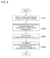
- FIG. 4 is a flowchart schematically showing a method of calibrating a load measurement apparatus according to an embodiment.
- a plurality of strain data is obtained for each of a plurality of different conditions in which at least one of an azimuth angle or a pitch angle of the wind turbine blade 2 varies (strain-data acquisition step; S100).
- the steps S100, S200, and S300 are performed during a plurality of startups of the wind turbine 1, thereby obtaining a plurality of calibration parameters based on strain data obtained in the respective startups of the wind turbine 1.
- the load measurement apparatus 30 is calibrated (calibration step; S400) on the basis of at least one of the plurality of calibration parameters calculated in the calibration-parameter calculation step (S300) on the basis of the plurality of sets of strain data, each set being obtained in the strain-data acquisition step (S100) carried out in corresponding one of the past startups of the wind turbine 1.
- the load measurement apparatus 30 is calibrated for load measurement in the flap direction of the wind turbine blade 2.
- the load measurement apparatus 30 can be calibrated similarly for load measurement in the edge direction of the wind turbine blade 2.
- the strain-data acquisition command part 42 provides the load measurement apparatus 30 with a command to obtain a plurality of strain data for each of a plurality of different conditions among which at least one of an azimuth angle or a pitch angle of the wind turbine blade 2 varies, while the wind turbine 1 is being started.
- the strain-data acquisition command part 42 provides the load measurement apparatus 30 with a command to obtain strain data for each of four conditions in which the wind turbine blade 2 has respectively an azimuth angle of 0°, 90°, 180°, and 270° when the pitch angle ⁇ of the wind turbine blade 2 is a pitch angle ⁇ 1 between the full-feather position and the full-fine position, while the wind turbine 1 is being started.
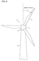
- An azimuth angle is an angle formed between a predetermined reference and an axis of the wind turbine blade 2 in a rotational plane of the wind turbine blade 2, as illustrated in FIG. 6 .
- the reference is the uppermost position of the wind turbine blade 2.
- the azimuth angle is 0° when the wind turbine blade 2 is at the uppermost position of the wind turbine blade 2
- the azimuth angle is 180° when the wind turbine blade 2 is at the lowermost position.
- FIG. 6 is a diagram for describing an azimuth angle of a wind turbine blade.
- the load measurement apparatus 30, having received a command from the strain-data acquisition command part 42, calculates the strain X flap in the flap direction of the wind turbine blade 2 as strain data by calculating a difference between strains detected by the strain sensors 32A, 32B mounted to the suction side 22 and the pressure side 24 of the blade root portion 12 of the wind turbine blade 2.
- strain data X flap_0 , X flap_90 , X flap_180 , X flap_270 are obtained for the four conditions, in which the blade 2 has a pitch angle of ⁇ 1 and an azimuth angle of 0°, 90°, 180° and 270°, respectively.
- a state during a startup of the wind turbine 1 refers to a state in which the wind turbine 1 is in a startup state that the wind turbine 1 passes through when a stop-standby state shifts to an operating state.
- FIG. 7 is a diagram of an example of a manner of change of a pitch angle of a wind turbine blade corresponding to transition of a state of a wind turbine.
- the pitch angle of each wind turbine blade 2 of the wind turbine 1 is at a feather position, and thus the rotation speed of the wind turbine rotor 6 is substantially zero.
- the startup state (a period from t 1 to t 4 in FIG. 7 )
- the pitch angle of the wind turbine blade 2 is shifted from the feather side toward the fine side so that the wind turbine rotor 6 rotates in response to wind received by the wind turbine blade 2, thereby increasing the rotation speed of the wind turbine rotor 6.
- the wind turbine 1 shifts to the operating state (a period from time t 4 in FIG. 7 ).
- an operating state is a state in which the rotation speed of the wind turbine rotor 6 and the rotation speed of the generator have increased sufficiently and the wind turbine power generating apparatus is connected to the grid.
- strain data of the wind turbine blade 2 may be obtained during the standby period in the strain-data acquisition step (S100).
- the pitch angle of each of the wind turbine blades 2 may be manipulated so that only one of the wind turbine blades 2 has a pitch angle for obtaining strain data, thereby obtaining strain data for the one of the wind turbine blades 2.
- the pitch angles of the other two wind turbine blades 2 may be changed to the full-feather position so as to minimize an increase in the rotation speed of the wind turbine rotor 6, thereby reducing an aerodynamic load applied to the wind turbine blade 2, which is a target of strain-data acquisition, as much as possible.
- the theoretical load-value acquisition part 46 obtains a theoretical load-value applied to the wind turbine blade 2 due to the own weight of the wind turbine blade 2 from the load-value reference table 44, for the plurality of conditions under which strain data of the wind turbine blade 2 has been obtained in the strain-data acquisition step (S100).
- the load-value reference table 44 is a table of a relationship of a pitch angle and an azimuth angle of the wind turbine blade 2 to a theoretical load value applied to the wind turbine blade 2 due to the own weight of the wind turbine blade 2, and stores theoretical load values associated with combinations of azimuth angles and pitch angles of the wind turbine blade 2.
- the theoretical load-value acquisition part 46 refers to the load-value reference table 44 for the four conditions under which the flap-direction strains (strain data) have been obtained in the strain-data acquisition step (S100), i.e., the four conditions that the wind turbine blade 2 has a pitch angle of ⁇ 1 and an azimuth angle of 0°, 90°, 180°, and 270°, respectively, and obtains theoretical values M flap_ex_0 , M flap_ex_90 , M flap_ex_180 , and M flap_ex_270 in the flap direction corresponding to the four conditions.
- the calibration-parameter calculation part 48 calculates a calibration parameter representing a relationship between strain data obtained by the load measurement apparatus 30 and a load on the wind turbine blade 2, on the basis of a correlation between each of the flap-direction strains (strain data) obtained in the strain-data acquisition step (S100), which are X flap_0 , X flap_90 , X flap_180 , and X flap_270 , and the theoretical load values in the flap direction obtained in the theoretical load value acquisition step (S200), which are M flap_ex_0 , M flap_ex_90 , M flap_ex_180 , and M flap_ex_270 .
- FIG. 8 is a diagram of an example of a correlation between a flap-direction strain and a flap-direction load.
- x-axis represents a flap-direction strain X flap and y-axis represents a flap-direction load M flap .
- M flap a f1 X flap + b f1 obtained by plotting four points, M flap_ex_0 , M flap_ex_90 , M flap_ex_180 , and M flap_ex_270 , which are the theoretical load values in the flap direction obtained in the theoretical load-value acquisition step (S200) corresponding to the respective flap-direction strains (strain data) obtained in the strain data acquisition step (S100), which are X flap_0 , X flap_90 , X flap_180 , and X flap_270 .
- the calibration-parameter calculation part 48 calculates an equation of the above line by the least-square method, for instance, and thereby obtains slope a f1 and intercept b f1 , which are calibration parameters related to the flap direction of the wind turbine blade 2, of the above line.
- strain-data acquisition step (S100), theoretical load-value acquisition step (S200), and calibration-parameter calculation step (S300) are carried out during multiple startups of the wind turbine 1.
- the strain-data acquisition step (S100) is carried out for the first time, and thereby flap-direction strains are obtained for respective cases in which the wind turbine blade 2 has a pitch angle of ⁇ 1 and an azimuth angle of 0°, 90°, 180°, and 270°.
- the theoretical load-value acquisition step (S200) theoretical load values in the flap direction are obtained, the theoretical load values corresponding to respective combinations of the pitch angle ( ⁇ 1 ) and the azimuth angles for which the flap-direction strains have been obtained.
- the calibration parameters calculated as described above may be accumulated in the calibration-parameter accumulation part 50.
- the calibration-parameter accumulation part 50 may accumulate a predetermined number (e.g. 100) of calibration parameters (a f1 to a f100 , and/or b f1 to b f100 ). If the number of calculated calibration parameters exceeds the predetermined number, the firstly-calculated calibration parameter may be deleted and the lastly-calculated calibration member may be stored in the calibration-parameter accumulation part 50, according to the first-in-first-out (FIFO) system.
- FIFO first-in-first-out
- the load measurement apparatus 30 is calibrated on the basis of at least one of the calibration parameters (a f1 , a f2 , ... a fn , and/or b f1 , b f2 , ...b fn ) calculated on the basis of a plurality of sets of flap-direction strains (strain data) obtained in the strain-data acquisition step (S100) carried out in respective past multiple (n times) startups of the wind turbine 1.
- the calibration parameters a f1 , a f2 , ... a fn , and/or b f1 , b f2 , ...b fn
- the past multiple startups of the wind turbine 1" during which strain data is to be obtained are any two or more startups of the wind turbine 1, and may not be necessarily successive startups.
- the pitch angle which is a strain-data acquisition condition of the wind turbine blade 2 for which strain-data is to be obtained, is within a range of from 40 to 60%.
- the pitch angle of the wind turbine blade 2 is shifted from the feather side toward the fine side so that the wind turbine rotor 6 rotates in response to wind received by the wind turbine blade 2.
- the pitch angle being within a range of from 40% to 60%, it is possible to obtain strain data for obtaining calibration parameters by utilizing the opportunity to shift the pitch angle of the wind turbine blade 2 from the feather side to the fine side during a startup of the wind turbine 1.
- strain data is to be obtained while the pitch angle of the wind turbine blade 2 is within a range of from 40 to 60%, it is possible to obtain strain data while a load due to the own weight of the wind turbine blade 2 is applied to some extent in both of the flap direction and the edge direction of the wind turbine blade 2.
- the load measurement apparatus 30 has a configuration that enables measurement of a load on the wind turbine blade 2 in the flap direction and the edge direction, it is possible to calibrate the load measurement apparatus 30 efficiently for both of the flap direction and the edge direction.
- strain data is obtained under each of four conditions that the pitch angle of the wind turbine blade 2 is constant and the azimuth angle of the wind turbine blade 2 is respectively 0°, 90°, 180°, and 270°.
- strain-data acquisition step (S100) if strain data is to be obtained for each of two conditions in which at least one of an azimuth angle or a pitch angle of the wind turbine blade 2 varies, it is preferable to obtain strain-data related to two conditions in which the azimuth angle is respectively 90° and 270°.
- an absolute value of a load due to the own weight of the wind turbine blade 2 reaches its maximum, and the direction of the load due to the own weight of the wind turbine blade 2 is opposite at an azimuth angle of 90° and 270° (i.e., a load is applied in a direction from the gravity center toward the pressure side 24 of the wind turbine blade 2 when the azimuth angle is 90°, and a load is applied in a direction from the gravity center toward the suction side 22 of the wind turbine blade 2 when the azimuth angle is 270°, for instance).
- a load is applied in a direction from the gravity center toward the pressure side 24 of the wind turbine blade 2 when the azimuth angle is 90°
- a load is applied in a direction from the gravity center toward the suction side 22 of the wind turbine blade 2 when the azimuth angle is 270°, for instance.
- the pitch angle of the wind turbine blade 2 may be at a position in the vicinity of the full feather position when the load measurement apparatus 30 is to be calibrated in the flap direction of the wind turbine blade 2.
- the pitch angle of the wind turbine blade 2 may be at a position in the vicinity of the full fine position when the load measurement apparatus 30 is to be calibrated in the edge direction of the wind turbine blade 2.
- the calibration part 40 calibrates the load measurement apparatus 30 on the basis of at least one of the calibration parameters (a f1 , a f2 ,...a fn , and/or b f1 , b f2 , ... b fn ) calculated on the basis of a plurality of sets of flap-direction strains (strain data) obtained in the strain-data acquisition step (S100) carried out in each of past multiple (n times) startups of the wind turbine 1.
- the calibration parameters a f1 , a f2 ,...a fn , and/or b f1 , b f2 , ... b fn
- FIG. 5 is a flowchart specifically showing the calibration step (S400) according to an embodiment.
- strain data based on strain obtained by the strain sensors 32 when the wind speed is not greater than a threshold value or when the rotation speed of the wind turbine rotor is not greater than a threshold value is extracted from among a plurality of sets of flap-direction strains (strain data) obtained by carrying out the strain-data acquisition step (S100) for multiple times (S402).
- a parameter-difference index is calculated, which represents a difference between a conversion calibration parameter currently used to convert strain data to a load by the load measurement apparatus 30 and at least one of the calibration parameters based on strain data extracted in S402 (S404).
- the conversion calibration parameter to be used by the load measurement apparatus 30 is updated on the basis of at least one of the calibration parameters based on the strain data extracted in S402 (S408).
- strain data based on strains obtained by the strain sensors 32 when the wind speed is not greater than a threshold value or when the rotation speed of the wind turbine rotor 6 is not greater than a threshold value from among a plurality of flap-direction strains (strain data) obtained by carrying out the strain-data acquisition steps (S100) for multiple times is extracted.
- a threshold value is not necessarily limited to when a momentary wind speed upon detection of a strain by the strain sensor 32 is not greater than a threshold value, and may be when a time average (e.g. average in 10 minutes) of wind speed is not greater than a threshold value, for instance.
- a time average e.g. average in 10 minutes
- a threshold value is not necessarily limited to when a momentary rotation speed upon detection of a strain by the strain sensor 32 is not greater than a threshold value, and may be when a time average (e.g. average in 10 minutes) of rotation speed is not greater than a threshold value.
- the threshold value of the wind speed may be not greater than 80% or not greater than 60% of a rated wind speed. Further, the threshold value of the rotation speed of the wind turbine rotor 6 may be not greater than 50% or not greater than 35% of a rated rotation speed.
- the load measurement apparatus 30 is calibrated using only the calibration parameters with an influence of an aerodynamic load reduced to some extent, which makes it possible to further improve accuracy of load measurement of the wind turbine blade 2.
- a parameter-difference index is calculated, which represents a difference between a conversion calibration parameter currently used to convert strain data to a load by the load measurement apparatus 30 and at least one of the calibration parameters based on strain data extracted in S402 (S404).
- the parameter-difference index calculated in S404 is a difference between the first load value obtained by converting a reference value of strain data using the conversion calibration parameter currently used by the load measurement apparatus 30, and the second load value obtained by converting the reference value using at least one of the calibration parameters calculated on the basis of the strain data extracted in S402.
- FIG. 9 is a diagram for describing a method of calculating a parameter-difference index.
- the load measurement apparatus 30 uses the above expression of F 0 to convert the strain data X flap in the flap direction obtained by the strain sensors 32 to the load M flap in the flap direction.
- the flap-direction strain data reference value X flap_ref is now a flap-direction strain that can be obtained using the conversion expression F 0 based on the conversion calibration parameters (a f0 , b f0 ) currently used on a flap-direction load M flap_ref of a predetermined magnitude (e.g. 5000kNm).
- the first load value is a flap-direction load M flap_ref obtained by converting the flap-direction strain data reference value X flap_ref by using the conversion expression F 0 based on the conversion calibration parameters (a f0 , b f0 ) currently used by the load measurement apparatus 30.
- the second load value is a flap-direction load M flap_Xref obtained by converting the flap-direction strain data reference value X filap_ref by using the conversion expression F 1 based on the calibration parameters (a f1 , b f1 ) calculated on the basis of the strain data extracted in S402.
- a difference between the first load value and the second value obtained as described above, represented by an expression of ⁇ M
- , is the parameter-difference index I 1 .
- a parameter-difference index I may be obtained for all of the calibration parameters, or for only a part of the calibration parameters.
- the parameter-difference index I calculated in S404 is compared with an allowable range. If the parameter-difference index I is greater than the allowable range (NO in S406), in the next step S408, the conversion calibration parameter is updated to convert strain data into load by the load measurement apparatus 30. In contrast, if the parameter-difference index I is within the allowable range (YES in S406), the conversion calibration parameter is not updated.
- the allowable range to be compared with the parameter-difference index I may be a load-value range obtained by multiplying the flap-direction load M flap_ref of a predetermined magnitude corresponding to the flap-direction strain data reference value X flap_ref by a predetermined ratio.
- the allowable range may be a range of from minus 500kNm to 500kNm, obtained by multiplying 5000kNm by minus 10% to 10%.
- each of the plurality of parameter-difference indexes I calculated in S404 is compared with the allowable range, and if a predetermined number of parameter-difference indexes I exceeds the allowable range, the conversion calibration parameter may be updated in the next step S408. For instance, if three parameter-difference indexes I recently calculated exceed the allowable range in a row, the conversion calibration parameter may be updated in the next step S408.
- a parameter-difference index I exceeds the allowable range, it can be determined that drift has taken place in the strain sensor 32 having obtained the strain data from which the parameter-difference index I has been calculated. Thus, if the parameter-difference index I exceeds the allowable range, a warning alert may be issued to draw attention to occurrence of drift of the strain sensor 32.
- the conversion calibration parameter currently used to convert strain data to load by the load measurement apparatus 30 is updated to a new conversion calibration parameter determined by the conversion-parameter determination part 52.
- conversion calibration parameter currently used may be those obtained in the initial calibration performed only once during installation of the wind turbine.
- conversion calibration parameter currently used may be determined on the basis of at least one calibration parameter obtained by carrying out the above described strain-data acquisition step (S100), theoretical load-value acquisition step (S200), and calibration-parameter calculation step (S300).
- the conversion-parameter determination part 52 may calculate a new conversion calibration parameter using statistic values of two or more of the plurality of calibration parameters based on the strain data extracted in S402. For instance, the conversion-parameter determination part 52 may calculate a mean of the plurality of calibration parameters based on the strain data extracted in S402 as a new conversion calibration parameter.
- the load measurement apparatus 30 with a conversion calibration parameter updated in S408 uses the updated (new) conversion calibration parameter to convert flap-direction strain data obtained by the strain sensors 32 into a load value in the flap direction.
- a calibration parameter representing a relationship between strain data and load on the wind turbine blade 2 is calculated on the basis of strain data obtained during startups of the wind turbine 1, which makes it possible to accurately calibrate the load measurement apparatus 30 while reducing an influence from drift of the strain sensors 32, even if drift of the strain sensors 32 occurs with time after construction of the wind turbine 1.
- the load measurement apparatus 30 is calibrated on the basis of at least one of the plurality of calibration parameters calculated on the basis of the plurality of sets of strain data obtained during past multiple startups of the wind turbine 1, which makes it possible to perform load measurement of the wind turbine blade 2 accurately.
- an expression of relative or absolute arrangement such as “in a direction”, “along a direction”, “parallel”, “orthogonal”, “centered”, “concentric” and “coaxial” shall not be construed as indicating only the arrangement in a strict literal sense, but also includes a state where the arrangement is relatively displaced by a tolerance, or by an angle or a distance whereby it is possible to achieve the same function.
- an expression of an equal state such as “same” “equal” and “uniform” shall not be construed as indicating only the state in which the feature is strictly equal, but also includes a state in which there is a tolerance or a difference that can still achieve the same function.
- an expression of a shape such as a rectangular shape or a cylindrical shape shall not be construed as only the geometrically strict shape, but also includes a shape with unevenness or chamfered corners within the range in which the same effect can be achieved.
Landscapes
- Engineering & Computer Science (AREA)
- Physics & Mathematics (AREA)
- General Physics & Mathematics (AREA)
- Life Sciences & Earth Sciences (AREA)
- Sustainable Development (AREA)
- Sustainable Energy (AREA)
- Chemical & Material Sciences (AREA)
- Combustion & Propulsion (AREA)
- Mechanical Engineering (AREA)
- General Engineering & Computer Science (AREA)
- Aviation & Aerospace Engineering (AREA)
- Wind Motors (AREA)
Abstract
Description
- The present disclosure relates to a method of calibrating a load measurement apparatus for measuring a load on a wind turbine blade, a load measurement system of a wind turbine blade, and a wind turbine.
- In a known method, a load applied to a wind turbine blade is measured on the basis of a strain of the wind turbine blade, to perform operation control for load reduction or to monitor a state of a wind turbine blade.
- For instance,
Patent Document 1 discloses obtaining a strain of a wind turbine blade using a sensor mounted to the wind turbine blade, and calculating a load on the wind turbine blade on the basis of a function representing a relationship between the strain and the load on a wind turbine blade. - Further,
Patent Document 1 discloses calibrating the above function representing a relationship between strain and load on a wind turbine blade, on the basis of measurement data of a strain obtained by a sensor and a theoretical load in a no-wind condition calculated on the basis of a given blade weight, of a pitch angle and of an azimuth angle (a rotational position of the blade) of the wind turbine blade. - Patent Document 1:
US 2012/035865 A - Normally, a function representing a correlation between strain and load on a wind turbine blade used for measuring a load on the wind turbine blade is calibrated only once during construction of a wind turbine. After operation of the wind turbine is started, a load is calculated on the basis of the above function calibrated during construction.
- However, an output value of a strain sensor for detecting a strain of the wind turbine blade may become inaccurate with time, which is a phenomenon called drift. If drift of a strain sensor takes place, the strain sensor indicates an output value different from that before occurrence of drift for a load of the same magnitude. Thus, the correlation between strain and load may also change. Accordingly, if a load is calculated on the basis of the function representing a correlation between strain and load calibrated during construction of the wind turbine, there may be a great error from an actual load.
- In this regard,
Patent Document 1 does not mention taking into account drift of a strain sensor in measurement of a load on a wind turbine blade. - In view of this, an object of at least one embodiment of the present invention is to provide a method of calibrating a load measurement apparatus capable of reducing an influence from a drift of a strain sensor.
- (1) A method of calibrating a load measurement apparatus for measuring a load on a wind turbine blade on the basis of strain data based on a strain of the wind turbine blade, according to at least one embodiment of the present invention, comprises: a strain-data acquisition step of, during a startup of a wind turbine, obtaining a plurality of the strain data for each of a plurality of conditions in which at least one of an azimuth angle or a pitch angle of the wind turbine blade varies; a theoretical load-value acquisition step of obtaining a theoretical load value applied to the wind turbine blade due to the own weight of the wind turbine blade, for each of the plurality of conditions, on the basis of the azimuth angle and the pitch angle of the wind turbine blade in each of the plurality of conditions; and a calibration-parameter calculation step of calculating a calibration parameter representing a relationship between the strain data obtained by the load measurement apparatus and the load on the wind turbine blade, on the basis of a correlation between each of the strain data and the theoretical load value.
According to the above method (1), a calibration parameter representing a relationship between strain data and a load on the wind turbine blade is calculated on the basis of strain data obtained during a startup of the wind turbine. In this way, it is possible to accurately calibrate the load measurement apparatus while reducing an influence from a drift of the strain sensors, even if the drift of the strain sensors occurs with time after construction of the wind turbine.
Further, since the calibration parameter is calculated on the basis of a theoretical load value acting on the wind turbine blade due to the own weight of the wind turbine blade, it is desirable to obtain strain data for calibration when an aerodynamic load is as small as possible. In this regard, during a startup of the wind turbine, the rotation speed of the wind turbine rotor is relatively low and an aerodynamic load is relatively small. Further, if the wind turbine is started after the wind turbine stops due to a wind-speed decrease and then the wind speed increases again, the aerodynamic load is even smaller because the wind speed is relatively low. Thus, calculating a calibration parameter on the basis of strain data obtained during a startup of the wind turbine makes it possible to reduce an influence of an aerodynamic load and to calibrate the load measurement apparatus accurately. - (2) In some embodiments, the above method (1) further comprises a calibration step of calibrating the load measurement apparatus on the basis of at least one of a plurality of calibration parameters calculated on the basis of a plurality of sets of the strain data obtained in the strain-data acquisition step carried out in respective past multiple startups of the wind turbine.
Normally, the wind speed at a startup of the wind turbine varies for different startups of the wind turbine, and thus strain data obtained during a startup of the wind turbine may be affected by a different aerodynamic load in each startup of the wind turbine. In this regard, according to the above method (2), the load measurement apparatus is calibrated on the basis of at least one of a plurality of calibration parameters calculated on the basis of the plurality of sets of strain data obtained during past multiple startups of the wind turbine, which makes it possible to perform load measurement of the wind turbine blade accurately. - (3) In some embodiments, in the above method (2), the calibration step comprises calibrating the load measurement apparatus by using statistic values of two or more of the plurality of calibration parameters.
According to the above method (3), the load measurement apparatus is calibrated by using two or more of the plurality of calibration parameters, which makes it possible to further improve accuracy of load measurement of the wind turbine blade. - (4) In some embodiments, in the above method (2) or (3), the calibration step comprises calculating a parameter-difference index representing a difference between at least one of the plurality of calibration parameters and a conversion calibration parameter currently used by the load measurement apparatus to convert the strain data into the load, and updating the conversion calibration parameter on the basis of at least one of the plurality of calibration parameters if the parameter-difference index exceeds an allowable range.
According to the above method (4), a parameter difference index is calculated to be compared with an allowable range, which makes it possible to determine occurrence of a drift of the strain sensor from a point of time when the currently-used conversion calibration parameter is calculated to a point of time when the calibration parameter used to calculate the parameter difference index is calculated. Further, if the parameter difference index exceeds the allowable range, the conversion calibration parameter is updated on the basis of the calculated calibration parameter, which makes it possible to calibrate taking account of fluctuation of strain data due to a drift of the strain sensor, which makes it possible to reduce a measurement error of a load due to the drift. - (5) In some embodiments, in the above method (4), the parameter-difference index is a difference between a first load value obtained by converting a reference value of the strain data by using the conversion calibration parameter, and a second load value obtained by converting the reference value by using at least one of the plurality of calibration parameters.
As described above, with the parameter difference index being a difference between the first load value and the second load value, it is possible to directly evaluate an influence of a magnitude of an error of the conversion calibration parameter due to a drift of the strain sensor on a measurement result of the load measurement apparatus. Thus, it is possible to update the conversion calibration parameter suitably when it is no longer possible to ignore an influence from a drift of the strain sensor on a measurement result of the load measurement apparatus. - (6) In some embodiments, in any of the above methods (2) to (5), the calibration step comprises calibrating the load measurement apparatus by using only at least one of the plurality of calibration parameters, the at least one calibration parameter being calculated from the strain data obtained when a wind speed is not greater than a threshold value or when a rotation speed of a wind turbine rotor is not greater than a threshold value in the strain-data acquisition step.
According to the above method (6), the load measurement apparatus is calibrated by using the calibration parameter calculated from strain data obtained when the wind speed is not greater than a threshold value or the rotation speed of the wind turbine rotor is not greater than a threshold value. Specifically, the load measurement apparatus is calibrated using the calibration parameters with a reduced influence of an aerodynamic load applied to the wind turbine blade, which makes it possible to further improve accuracy of load measurement of the wind turbine blade. - (7) In some embodiments, in the above method (6), the threshold value of the wind speed is not greater than 80% of a rated wind speed, or the threshold value of the rotation speed of the wind turbine rotor is not greater than 50% of a rated rotation speed.
According to findings of the present inventors, if the wind speed is not greater than 80% of a rated wind speed, or the rotation speed of the wind turbine rotor is not greater than 50% of a rated rotation speed, calculation of a calibration parameter is less affected by an aerodynamic load applied to the wind turbine blade. Thus, according to the above method (7), the load measurement apparatus is calibrated by using only the calibration parameters with an influence of an aerodynamic load reduced to some extent, which makes it possible to further improve accuracy of load measurement of the wind turbine blade. - (8) In some embodiments, in any of the above methods (1) to (7), in the strain-data acquisition step, when a feather angle of a pitch angle of the wind turbine blade is represented as 0% and a fine angle as 100%, the strain data is obtained while the pitch angle of the wind turbine blade is within a range of from 40 to 60%.
During a startup of the wind turbine, the pitch angle of the wind turbine blade is shifted from the feather side to the fine side so that the wind turbine rotor rotates when the wind turbine blade receives wind. According to the above method (8), it is possible to obtain strain data for obtaining calibration parameters by utilizing the opportunity to shift the pitch angle of the wind turbine blade from the feather side to the fine side during a startup of the wind turbine.
Further, a load on the wind turbine blade may be measured in a flap direction and an edge direction of the wind turbine blade. An edge direction of the wind turbine blade is a cord direction connecting a leading edge and a trailing edge in a cross section orthogonal to the longitudinal direction of the wind turbine blade, and a flap direction is a direction orthogonal to the cord direction in the cross section. According to the above method (8), strain data is obtained while the pitch angle of the wind turbine blade is within a range of from 40 to 60%, which makes it possible to obtain strain data while a load due to the own weight of the wind turbine blade is applied to some extent in both of the flap direction and the edge direction of the wind turbine blade. Thus, even if the load measurement apparatus has a configuration that enables measurement of a load on the wind turbine blade in the flap direction and the edge direction, it is possible to calibrate the load measurement apparatus efficiently for both of the flap direction and the edge direction. - (9) A load measurement system for a wind turbine blade according to at least one embodiment of the present invention comprises: a load measurement apparatus configured to measure a load on the wind turbine blade of a wind turbine on the basis of strain data based on strain of the wind turbine blade; and a calibration part configured to calibrate the load measurement apparatus, the calibration part comprising: a strain-data acquisition command part configured to provide the load measurement apparatus with a command to, during a startup of a wind turbine, obtain a plurality of the strain data for each of a plurality of conditions in which at least one of an azimuth angle or a pitch angle of the wind turbine blade varies; a theoretical load-value acquisition part configured to obtain a theoretical load value applied to the wind turbine blade due to the own weight of the wind turbine blade, for each of the plurality of conditions, on the basis of the azimuth angle and the pitch angle of the wind turbine blade in each of the plurality of conditions; and a calibration-parameter calculation part configured to calculate a calibration parameter representing a relationship between the strain data obtained by the load measurement apparatus and the load on the wind turbine blade, on the basis of a correlation between each of the strain data and the theoretical load value.
With the above configuration (9), a calibration parameter representing a relationship between strain data and a load on the wind turbine blade is calculated on the basis of strain data obtained during a startup of the wind turbine. In this way, it is possible to accurately calibrate the load measurement apparatus while reducing an influence from a drift of the strain sensors, even if the drift of the strain sensors occurs with time after construction of the wind turbine.
Further, since the calibration parameter is calculated on the basis of a theoretical load value acting on the wind turbine blade due to the own weight of the wind turbine blade, it is desirable to obtain strain data for calibration when an aerodynamic load is as small as possible. In this regard, during a startup of the wind turbine, the rotation speed of the wind turbine rotor is relatively low and an aerodynamic load is relatively small. Further, if the wind turbine is started after the wind turbine stops due to a wind-speed decrease and then the wind speed increases again, the aerodynamic load is small because the wind speed is relatively low. Thus, calculating a calibration parameter on the basis of strain data obtained during a startup of the wind turbine makes it possible to reduce an influence of an aerodynamic load and to calibrate the load measurement apparatus accurately. - (10) In some embodiments, in the above configuration (9), the calibration part is configured to calibrate the load measurement apparatus on the basis of at least one of a plurality of calibration parameters calculated on the basis of a plurality of sets of the strain data obtained on the basis of the command of the strain-data acquisition command part in respective past multiple startups of the wind turbine.
Normally, the wind speed at a startup of the wind turbine varies for different startups of the wind turbine, and thus strain data obtained during a startup of the wind turbine may be affected by a different aerodynamic load in each startup of the wind turbine. In this regard, with the above configuration (10), the load measurement apparatus is calibrated on the basis of at least one of the plurality of calibration parameters calculated on the basis of the plurality of sets of strain data obtained during past multiple startups of the wind turbine, which makes it possible to perform load measurement of the wind turbine blade accurately. - (11) In some embodiments, in the above configuration (9) or (10), the calibration parameter calculation part is configured to calculate the calibration parameter using only the strain data obtained when a wind speed is not greater than a threshold value or when a rotation speed of a wind turbine rotor is not greater than a threshold value, from among the plurality of strain data obtained on the basis of the command of the strain-data acquisition command part.
With the above configuration (11), the load measurement apparatus is calibrated by using the calibration parameter calculated from strain data obtained when the wind speed is not greater than a threshold value or the rotation speed of the wind turbine rotor is not greater than a threshold value. Specifically, the load measurement apparatus is calibrated using the calibration parameters with a reduced influence of an aerodynamic load applied to the wind turbine blade, which makes it possible to further improve accuracy of load measurement of the wind turbine blade. - (12) In some embodiments, in any of the above configurations (9) to (11), the load measurement apparatus includes a pair of strain sensors disposed on opposite sides of the wind turbine blade and configured to detect a strain of the wind turbine blade at respective mounting positions of the wind turbine blade, and the load measurement apparatus is configured to obtain a difference between respective detection results of the pair of strain sensors as the strain data.
With the above configuration (12), it is possible to obtain strain data of the wind turbine blade by using a pair of strain sensors mounted to the opposite sides of the wind turbine blade. - (13) In some embodiments, in the above configuration (12), the strain sensors are fiber-optic sensors each including a diffraction grating portion with a refractive index which periodically changes in a longitudinal direction, and the fiber-optic sensors are configured to detect a strain of the wind turbine blade on the basis of a wavelength of reflected light which is a light having entered the fiber-optic sensor and reflected by the diffraction grating portion.
In general, a fiber-optic sensor is less sensitive to a drift than a strain gauge, and thus it is considered that an influence from the drift can be ignored. However, the present inventors found that a drift may occur with time even if a fiber-optic sensor is used and a load measurement result may be somewhat affected. In this regard, with the above configuration (13), in a case where a fiber-optic sensor is used as a strain sensor, the load measurement apparatus is calibrated appropriately with the configuration of the above (12), which makes it possible to reduce an error in a load measurement result due to a drift of the fiber-optic sensor. - (14) A wind turbine according to at least one embodiment of the present invention comprises: a wind turbine rotor comprising a wind turbine blade; and a load measurement system of a wind turbine blade according to any one of the above (9) to (13), the load measurement system being configured to measure a load on the wind turbine blade on the basis of strain data based on strain of the wind turbine blade.
With the above configuration (14), a calibration parameter representing a relationship between strain data and a load on the wind turbine blade is calculated on the basis of strain data obtained during a startup of the wind turbine. In this way, it is possible to accurately calibrate the load measurement apparatus while reducing an influence from a drift of the strain sensors, even if the drift of the strain sensors occurs with time after construction of the wind turbine. - Further, since the calibration parameter is calculated on the basis of a theoretical load value acting on the wind turbine blade due to the own weight of the wind turbine blade, it is desirable to obtain strain data for calibration when an aerodynamic load is as small as possible. In this regard, during a startup of the wind turbine, the rotation speed of the wind turbine rotor is relatively low and an aerodynamic load is relatively small. Further, if the wind turbine is started after the wind turbine stops due to a wind-speed decrease and then the wind speed increases again, the aerodynamic load is even smaller because the wind speed is relatively low. Thus, calculating a calibration parameter on the basis of strain data obtained during a startup of the wind turbine makes it possible to reduce an influence of an aerodynamic load and to calibrate the load measurement apparatus accurately.
- According to at least one embodiment of the present invention, it is possible to provide a method of calibrating a load measurement apparatus capable of reducing an influence from a drift of a strain sensor.
-
-
FIG. 1 is a schematic diagram of an overall configuration of a wind turbine according to an embodiment. -
FIG. 2 is a block diagram of a schematic configuration of a load measurement system according to an embodiment. -
FIG. 3 is a cross-sectional view of a blade root portion of the wind turbine blade illustrated inFIG. 1 , taken along a direction orthogonal to a longitudinal direction of the wind turbine blade. -
FIG. 4 is a flowchart schematically showing a method of calibrating a load measurement apparatus according to an embodiment. -
FIG. 5 is a flowchart specifically showing a calibrating step according to an embodiment. -
FIG. 6 is a diagram for describing an azimuth angle of a wind turbine blade according to an embodiment. -
FIG. 7 is a diagram of an example of a manner of change of a pitch angle of a wind turbine blade with respect to transition of a state of a wind turbine according to an embodiment. -
FIG. 8 is a diagram of an example of a correlation between a flap-direction strain and a flap-direction load. -
FIG. 9 is a diagram for describing a method of calculating a parameter-difference index. - Embodiments of the present invention will now be described in detail with reference to the accompanying drawings. It is intended, however, that unless particularly specified, dimensions, materials, shapes, relative positions and the like of components described in the embodiments shall be interpreted as illustrative only and not intended to limit the scope of the present invention.
- First, a configuration of a wind turbine including a wind turbine blade, which is a measurement target of the present invention, will be described.
-
FIG. 1 is a schematic diagram of an overall configuration of awind turbine 1 according to an embodiment of the present invention. As illustrated in the drawing, thewind turbine 1 includes awind turbine rotor 6 including a plurality ofwind turbine blades 2 and ahub 4 to which the plurality ofwind turbine blades 2 is mounted, a nacelle 8, and atower 10 supporting the nacelle 8. In thewind turbine 1 illustrated inFIG. 1 , threewind turbine blades 2 are mounted to thehub 4. In thiswind turbine 1, in response to wind received by thewind turbine blades 2, thewind turbine rotor 6 including thewind turbine blades 2 and thehub 4 rotates about a rotational axis. Further, thewind turbine 1 includes a load measurement system 20 (not illustrated inFIG. 1 ) for measuring a load on thewind turbine blades 2. - The
wind turbine 1 may be a wind turbine power generating apparatus. In this case, the nacelle 8 may house a generator and a power transmission mechanism for transmitting rotation of thewind turbine rotor 6 to the generator. Thewind turbine 1 may be configured such that rotational energy of thewind turbine rotor 6 is transmitted to the generator by the power transmission mechanism to be converted into electric energy by the generator. - Next, with reference to
FIGs. 1 to 3 , the configuration of theload measurement system 20 according to an embodiment will be described.FIG. 2 is a block diagram of a schematic configuration of a load measurement system according to an embodiment.FIG. 3 is a cross-sectional view of a blade root portion of the wind turbine blade illustrated inFIG. 1 , taken along a direction orthogonal to a longitudinal direction of the wind turbine blade. - As illustrated in
FIG. 2 , theload measurement system 20 includes aload measurement apparatus 30 which measures a load on thewind turbine blades 2 on the basis of strain data based on a strain of thewind turbine blades 2 and acalibration part 40 for calibrating theload measurement apparatus 30. - The
load measurement apparatus 30 includes astrain sensor 32 mounted to thewind turbine blade 2 and configured to detect a strain of thewind turbine blades 2, and aload calculation part 34 for calculating a load on thewind turbine blade 2 on the basis of strain data obtained by using thestrain sensor 32. - In the
wind turbine 1 illustrated inFIG. 1 , thestrain sensor 32 is disposed on the blade root portion 12 (seeFIG. 1 ) of eachwind turbine blade 2. It should be noted that, in thewind turbine 1 illustrated inFIG. 1 , theblade root portion 12 is a structural portion constituting an end portion of thewind turbine blade 2, the end portion being adjacent to thehub 4. Theblade root portion 12 has a cylindrical shape and receives a bending moment transmitted to thehub 4 from thewind turbine blade 2. - Whereas all (three) of the wind turbine blades each have a
strain sensor 32 disposed on theblade root portion 12, thestrain sensor 32 may not necessarily be mounted to every one of thewind turbine blades 2. It is sufficient if thestrain sensor 32 is mounted to each ofwind turbine blades 2 which are targets of load measurement. - Now, with reference to
FIG. 3 , the position of thestrain sensors 32 and strain data obtained by thestrain sensors 32 will be described.FIG. 3 is a cross-sectional view of theblade root portion 12 of thewind turbine blade 2 illustrated inFIG. 1 , taken along a direction orthogonal to a longitudinal direction of the wind turbine blade. InFIG. 3 , an edge direction is a cord direction connecting aleading edge 26 and a trailingedge 28 in a cross section orthogonal to the longitudinal direction of thewind turbine blade 2, and a flap direction is a direction orthogonal to the cord direction in the cross section. - A pair of
strain sensors strain sensors blade root portion 12 of thewind turbine blade 2 illustrated inFIGs. 1 and3 . Thestrain sensors wind turbine blade 2 along the flap direction, and thestrain sensors wind turbine blade 2 along the edge direction. Specifically, thestrain sensors 32A to 32D are respectively disposed on asuction side 22, apressure side 24, a side of the leadingedge 26, and a side of the trailingedge 28, of theblade root portion 12 of thewind turbine blade 2. Strain of respective positions at which thestrain sensors 32A to 32D are mounted can be obtained on the basis of measurement data measured by theabove strain sensors 32A to 32D. - The strain data includes values based on the strains detected by the
strain sensors 32. - For instance, it is possible to calculate a strain Xflap in the flap direction of the
wind turbine blade 2 by calculating a difference between the strains obtained by thestrain sensors suction side 22 and thepressure side 24 of theblade root portion 12 of thewind turbine blade 2. Further, it is possible to calculate a strain Xedge in the edge direction of thewind turbine blade 2 by calculating a difference between the strains obtained by thestrain sensors edge 26 and the side of the trailingedge 28 of theblade root portion 12 of thewind turbine blade 2. The strain Xflap in the flap direction and the strain Xedge in the edge direction can be used as strain data. - A strain in the flap direction of the
wind turbine blade 2 and a load in the flap direction have a correlation, and thus it is possible to calculate a load in the flap direction of thewind turbine blade 2 on the basis of the strain Xflap in the flap direction of thewind turbine blade 2. Further, a strain in the edge direction of thewind turbine blade 2 and a load in the edge direction have a correlation, and thus it is possible to calculate a load in the edge direction of thewind turbine blade 2 on the basis of the strain Xedge in the edge direction of thewind turbine blade 2. - To measure a load in the flap direction for the
wind turbine blade 2, which is a target of load measurement, thewind turbine blade 2 only needs to have at least thestrain sensors 32 for obtaining the strain Xflap in the flap direction, specifically, the pair ofstrain sensors suction side 22 and thepressure side 24 of thewind turbine blade 2. Further, to measure a load in the edge direction for thewind turbine blade 2, which is a target of load measurement, thewind turbine blade 2 only needs to have at least thestrain sensors 32 for obtaining the strain Xedge in the edge direction, specifically, the pair ofstrain sensors edge 26 and the side of the trailingedge 28 of thewind turbine blade 2. - In an embodiment, the
strain sensors 32 are fiber-optic sensors including a diffraction grating portion with a refractive index that periodically changes in the longitudinal direction. The fiber-optic sensor is configured to detect a strain of thewind turbine blade 2 on the basis of the wavelength of reflected light which is a light having entered the fiber-optic sensor and reflected by the diffraction grating portion. - If a strain applied to the fiber-optic sensor changes, a grating period of the diffraction grating portion also changes. Thus, the wavelength of reflected light, which is a light having entered the optic fiber and reflected by the diffraction grating portion, changes in accordance with the change of the grating period. Accordingly, it is possible to detect a strain on the basis of the wavelength of the reflected light reflected by the diffraction grating portion.
- As a fiber-optic sensor described above, a fiber Bragg grating (FBG) sensor can be used, for instance.
- In an embodiment, the
strain sensor 32 is a strain gauge such as a metallic strain gauge and a semiconductor strain gauge. - Whereas the
strain sensors 32 are mounted to theblade root portion 12 of thewind turbine blade 2 in the embodiment illustrated inFIGs. 1 and3 , in an embodiment, thestrain sensors 32 may be mounted to a tip portion (an end remote from the hub) of thewind turbine blade 2. In an embodiment, thestrain sensors 32 may be mounted to a zone between theblade root portion 12 and the tip portion of thewind turbine blade 2. - Further, in an embodiment, the
strain sensors 32 may be respectively disposed on thesuction side 22, thepressure side 24, the side of the leadingedge 26, and the side of the trailingedge 28 of thewind turbine blade 2, as illustrated inFIGs. 1 and3 . In an embodiment, a plurality ofstrain sensors 32 may be mounted along the longitudinal direction of thewind turbine blade 2. - The
load calculation part 34 is configured to calculate a load applied to thewind turbine blade 2 for each one of thewind turbine blades 2 with thestrain sensors 32 mounted thereto. - A strain of the
wind turbine blade 2 and a load applied to thewind turbine blade 2 have a correlation, and thus it is possible to calculate a load on thewind turbine blade 2 on the basis of strain data obtained by thestrain sensors 32 mounted to thewind turbine blade 2. - The
load calculation part 34 calculates a load on thewind turbine blade 2 from strain data obtained by thestrain sensors 32 on the basis of a parameter representing a correlation between strain and load on thewind turbine blade 2. - In an embodiment, a conversion calibration parameter described below is used as a parameter representing a correlation between strain and load on the
wind turbine blade 2. - The
calibration part 40 is configured to calibrate theload measurement apparatus 30. With thecalibration part 40 calibrating theload measurement apparatus 30, it is possible to reduce an influence from a drift of thestrain sensors 32 and perform load measurement of a wind turbine blade accurately, even if a drift of thestrain sensors 32 has taken place. - As illustrated in
FIG. 2 , thecalibration part 40 includes a strain-dataacquisition command part 42, a load-value reference table 44, a theoretical load-value acquisition part 46, a calibration-parameter calculation part 48, a calibration-parameter accumulation part 50, and a conversion-parameter determination part 52. - A method of calibrating the
load measurement apparatus 30 according to an embodiment is carried out by thecalibration part 40 with the above configuration. A method of calibrating theload measurement apparatus 30 carried out by thecalibration part 40 with the above configuration will now be described with reference toFIGs. 4 to 9 . - Whereas the following description focuses on one of the
wind turbine blades 2 constituting thewind turbine rotor 6 to describe a method of measuring a load on thewind turbine blade 2, a load can be measured for the otherwind turbine blades 2 by the same method. -
FIG. 4 is a flowchart schematically showing a method of calibrating a load measurement apparatus according to an embodiment. As illustrated in the flowchart ofFIG. 4 , in a method of calibrating theload measurement apparatus 30 according to an embodiment, firstly, while thewind turbine 1 is being started, a plurality of strain data is obtained for each of a plurality of different conditions in which at least one of an azimuth angle or a pitch angle of thewind turbine blade 2 varies (strain-data acquisition step; S100). - Next, on the basis of the azimuth angle and the pitch angle of the
wind turbine blade 2 under each of the plurality of conditions for which the strain data has been obtained in S100, a theoretical load value applied to thewind turbine blade 2 due to the own weight of thewind turbine blade 2 is obtained for each of the plurality of conditions (theoretical load-value acquisition step; S200). - Next, on the basis of a correlation between each of the strain data obtained in S100 and the theoretical load value obtained in S200, a calibration parameter representing a relationship between strain data obtained by the
load measurement apparatus 30 and a load on thewind turbine blade 2 is calculated (calibration-parameter calculation step; S300). - The steps S100, S200, and S300 are performed during a plurality of startups of the
wind turbine 1, thereby obtaining a plurality of calibration parameters based on strain data obtained in the respective startups of thewind turbine 1. - Then, the
load measurement apparatus 30 is calibrated (calibration step; S400) on the basis of at least one of the plurality of calibration parameters calculated in the calibration-parameter calculation step (S300) on the basis of the plurality of sets of strain data, each set being obtained in the strain-data acquisition step (S100) carried out in corresponding one of the past startups of thewind turbine 1. - Now, each of the above steps S100 to S400 will be described specifically. In the following description, the
load measurement apparatus 30 is calibrated for load measurement in the flap direction of thewind turbine blade 2. However, theload measurement apparatus 30 can be calibrated similarly for load measurement in the edge direction of thewind turbine blade 2. - In the strain-data acquisition step (S100), the strain-data
acquisition command part 42 provides theload measurement apparatus 30 with a command to obtain a plurality of strain data for each of a plurality of different conditions among which at least one of an azimuth angle or a pitch angle of thewind turbine blade 2 varies, while thewind turbine 1 is being started. In the present embodiment, the strain-dataacquisition command part 42 provides theload measurement apparatus 30 with a command to obtain strain data for each of four conditions in which thewind turbine blade 2 has respectively an azimuth angle of 0°, 90°, 180°, and 270° when the pitch angle θ of thewind turbine blade 2 is a pitch angle θ1 between the full-feather position and the full-fine position, while thewind turbine 1 is being started. - An azimuth angle is an angle formed between a predetermined reference and an axis of the
wind turbine blade 2 in a rotational plane of thewind turbine blade 2, as illustrated inFIG. 6 . In the present specification, the reference is the uppermost position of thewind turbine blade 2. In this case, the azimuth angle is 0° when thewind turbine blade 2 is at the uppermost position of thewind turbine blade 2, and the azimuth angle is 180° when thewind turbine blade 2 is at the lowermost position.FIG. 6 is a diagram for describing an azimuth angle of a wind turbine blade. - The
load measurement apparatus 30, having received a command from the strain-dataacquisition command part 42, calculates the strain Xflap in the flap direction of thewind turbine blade 2 as strain data by calculating a difference between strains detected by thestrain sensors suction side 22 and thepressure side 24 of theblade root portion 12 of thewind turbine blade 2. In this way, flap-direction strains (strain data) Xflap_0, Xflap_90, Xflap_180, Xflap_270 are obtained for the four conditions, in which theblade 2 has a pitch angle of θ1 and an azimuth angle of 0°, 90°, 180° and 270°, respectively. - A state during a startup of the
wind turbine 1 refers to a state in which thewind turbine 1 is in a startup state that thewind turbine 1 passes through when a stop-standby state shifts to an operating state.FIG. 7 is a diagram of an example of a manner of change of a pitch angle of a wind turbine blade corresponding to transition of a state of a wind turbine. - In the stop-standby state (a period to time t1 in
FIG. 7 ), the pitch angle of eachwind turbine blade 2 of thewind turbine 1 is at a feather position, and thus the rotation speed of thewind turbine rotor 6 is substantially zero. In the startup state (a period from t1 to t4 inFIG. 7 ), the pitch angle of thewind turbine blade 2 is shifted from the feather side toward the fine side so that thewind turbine rotor 6 rotates in response to wind received by thewind turbine blade 2, thereby increasing the rotation speed of thewind turbine rotor 6. If the rotation speed of thewind turbine rotor 6 increases sufficiently in the startup state, thewind turbine 1 shifts to the operating state (a period from time t4 inFIG. 7 ). If thewind turbine 1 is a wind turbine power generating apparatus, an operating state is a state in which the rotation speed of thewind turbine rotor 6 and the rotation speed of the generator have increased sufficiently and the wind turbine power generating apparatus is connected to the grid. - For instance, as illustrated in
FIG. 7 , when the pitch angle of thewind turbine blade 2 is to be shifted from a feather position to a fine position during a startup of the wind turbine 1 (i.e., while thewind turbine 1 is in the startup state), if a standby period (a period from t2 to t3 inFIG. 7 ) of standby at a constant pitch angle θw between the full-feather position and the full-fine position is provided, strain data of thewind turbine blade 2 may be obtained during the standby period in the strain-data acquisition step (S100). - Alternatively, during a startup of the
wind turbine 1, in a stage before the pitch angle of thewind turbine blade 2 is shifted from a feather position to a fine position, the pitch angle of each of thewind turbine blades 2 may be manipulated so that only one of thewind turbine blades 2 has a pitch angle for obtaining strain data, thereby obtaining strain data for the one of thewind turbine blades 2. At this time, the pitch angles of the other twowind turbine blades 2 may be changed to the full-feather position so as to minimize an increase in the rotation speed of thewind turbine rotor 6, thereby reducing an aerodynamic load applied to thewind turbine blade 2, which is a target of strain-data acquisition, as much as possible. - In the theoretical load-value acquisition step (S200), the theoretical load-
value acquisition part 46 obtains a theoretical load-value applied to thewind turbine blade 2 due to the own weight of thewind turbine blade 2 from the load-value reference table 44, for the plurality of conditions under which strain data of thewind turbine blade 2 has been obtained in the strain-data acquisition step (S100). - The load-value reference table 44 is a table of a relationship of a pitch angle and an azimuth angle of the
wind turbine blade 2 to a theoretical load value applied to thewind turbine blade 2 due to the own weight of thewind turbine blade 2, and stores theoretical load values associated with combinations of azimuth angles and pitch angles of thewind turbine blade 2. - Specifically, the theoretical load-
value acquisition part 46 refers to the load-value reference table 44 for the four conditions under which the flap-direction strains (strain data) have been obtained in the strain-data acquisition step (S100), i.e., the four conditions that thewind turbine blade 2 has a pitch angle of θ1 and an azimuth angle of 0°, 90°, 180°, and 270°, respectively, and obtains theoretical values Mflap_ex_0, Mflap_ex_90, Mflap_ex_180, and Mflap_ex_270 in the flap direction corresponding to the four conditions. - In the calibration parameter calculation step (S300), the calibration-
parameter calculation part 48 calculates a calibration parameter representing a relationship between strain data obtained by theload measurement apparatus 30 and a load on thewind turbine blade 2, on the basis of a correlation between each of the flap-direction strains (strain data) obtained in the strain-data acquisition step (S100), which are Xflap_0, Xflap_90, Xflap_180, and Xflap_270, and the theoretical load values in the flap direction obtained in the theoretical load value acquisition step (S200), which are Mflap_ex_0, Mflap_ex_90, Mflap_ex_180, and Mflap_ex_270. - It is known that a correlation between a flap-direction strain Xflap and a flap-direction load Mflap of the
wind turbine blade 2 can be approximately represented by a primary expression of Mflap = aXflap + b. Thus, as a calibration parameter representing a correlation between a flap-direction strain Xflap and a flap-direction load Mflap, it is possible to use slope "a" and/or intercept "b" in the above expression. -
FIG. 8 is a diagram of an example of a correlation between a flap-direction strain and a flap-direction load. InFIG. 8 , x-axis represents a flap-direction strain Xflap and y-axis represents a flap-direction load Mflap. On this coordinate, when thewind turbine blade 2 has a pitch angle of θ1, a correlation between a flap-direction strain and a theoretical load value is represented by an approximate line Mflap = af1Xflap + bf1 obtained by plotting four points, Mflap_ex_0, Mflap_ex_90, Mflap_ex_180, and Mflap_ex_270, which are the theoretical load values in the flap direction obtained in the theoretical load-value acquisition step (S200) corresponding to the respective flap-direction strains (strain data) obtained in the strain data acquisition step (S100), which are Xflap_0, Xflap_90, Xflap_180, and Xflap_270. - The calibration-
parameter calculation part 48 calculates an equation of the above line by the least-square method, for instance, and thereby obtains slope af1 and intercept bf1, which are calibration parameters related to the flap direction of thewind turbine blade 2, of the above line. - The above described strain-data acquisition step (S100), theoretical load-value acquisition step (S200), and calibration-parameter calculation step (S300) are carried out during multiple startups of the
wind turbine 1. - For instance, during a startup of the
wind turbine 1, the strain-data acquisition step (S100) is carried out for the first time, and thereby flap-direction strains are obtained for respective cases in which thewind turbine blade 2 has a pitch angle of θ1 and an azimuth angle of 0°, 90°, 180°, and 270°. Then, in the theoretical load-value acquisition step (S200), theoretical load values in the flap direction are obtained, the theoretical load values corresponding to respective combinations of the pitch angle (θ1) and the azimuth angles for which the flap-direction strains have been obtained. In the calibration-parameter calculation step (S300), calibration parameters related to the flap direction of thewind turbine blade 2, which are slope af1 and intercept bf1 in the expression of Mflap = af1Xflap + bf1, are obtained on the basis of each flap-direction strain and each flap-direction theoretical load value. - Further, in another startup of the
wind turbine 1, the strain-data acquisition step (S100), the theoretical load-value acquisition step (S200), and the calibration-parameter calculation step (S300) are carried out for the second time, and calibration parameters related to the flap direction of thewind turbine blade 2, which are slope af2 and intercept bf2 in an expression of Mflap = af2Xflap + bf2, are obtained. - Similarly, in yet another startup of the
wind turbine 1, the strain-data acquisition step (S100), the theoretical load-value acquisition step (S200), and the calibration-parameter calculation step (S300) are carried out for the n-th time, and calibration parameters related to the flap direction of thewind turbine blade 2, which are slope afn and intercept bfn in an expression of Mflap = afnXflap + bfn, are obtained. - The calibration parameters calculated as described above (af1, af2,... afn, and/or bf1, bf2, ...bfn) may be accumulated in the calibration-
parameter accumulation part 50. The calibration-parameter accumulation part 50 may accumulate a predetermined number (e.g. 100) of calibration parameters (af1 to af100, and/or bf1 to bf100). If the number of calculated calibration parameters exceeds the predetermined number, the firstly-calculated calibration parameter may be deleted and the lastly-calculated calibration member may be stored in the calibration-parameter accumulation part 50, according to the first-in-first-out (FIFO) system. - In the calibration step (S400) described below, the
load measurement apparatus 30 is calibrated on the basis of at least one of the calibration parameters (af1, af2, ... afn, and/or bf1, bf2, ...bfn) calculated on the basis of a plurality of sets of flap-direction strains (strain data) obtained in the strain-data acquisition step (S100) carried out in respective past multiple (n times) startups of thewind turbine 1. - Accordingly, as many (n) calibration parameters (af1 to afn and/or bf1 to bfn) as the number of execution of strain-data acquisition step (S100) (n times), are calculated.
- "The past multiple startups of the
wind turbine 1" during which strain data is to be obtained are any two or more startups of thewind turbine 1, and may not be necessarily successive startups. - In an embodiment, in the strain-data acquisition step (S100), when a feather angle of a pitch angle of the
wind turbine blade 2 is represented as 0% and a fine angle as 100%, the pitch angle, which is a strain-data acquisition condition of thewind turbine blade 2 for which strain-data is to be obtained, is within a range of from 40 to 60%. - As described above, during a startup of the
wind turbine 1, the pitch angle of thewind turbine blade 2 is shifted from the feather side toward the fine side so that thewind turbine rotor 6 rotates in response to wind received by thewind turbine blade 2. Thus, with the pitch angle being within a range of from 40% to 60%, it is possible to obtain strain data for obtaining calibration parameters by utilizing the opportunity to shift the pitch angle of thewind turbine blade 2 from the feather side to the fine side during a startup of thewind turbine 1. - Further, if strain data is to be obtained while the pitch angle of the
wind turbine blade 2 is within a range of from 40 to 60%, it is possible to obtain strain data while a load due to the own weight of thewind turbine blade 2 is applied to some extent in both of the flap direction and the edge direction of thewind turbine blade 2. Thus, even if theload measurement apparatus 30 has a configuration that enables measurement of a load on thewind turbine blade 2 in the flap direction and the edge direction, it is possible to calibrate theload measurement apparatus 30 efficiently for both of the flap direction and the edge direction. - In the above description, in the strain-data acquisition step (S100), strain data is obtained under each of four conditions that the pitch angle of the
wind turbine blade 2 is constant and the azimuth angle of thewind turbine blade 2 is respectively 0°, 90°, 180°, and 270°. However, in the strain-data acquisition step, it is sufficient if strain-data is obtained for each of at least two conditions in which at least one of an azimuth angle or a pitch angle of thewind turbine blade 2 varies. If strain data is obtained under at least two conditions as described above, it is possible to obtain an approximate line representing a correlation between strain data and load on the basis of the strain data and corresponding theoretical load values, which makes is possible to calculate calibration parameters (slope and/or intercept of the approximate line). - In the strain-data acquisition step (S100), if strain data is to be obtained for each of two conditions in which at least one of an azimuth angle or a pitch angle of the
wind turbine blade 2 varies, it is preferable to obtain strain-data related to two conditions in which the azimuth angle is respectively 90° and 270°. - When the azimuth angle is 90° or 270°, an absolute value of a load due to the own weight of the
wind turbine blade 2 reaches its maximum, and the direction of the load due to the own weight of thewind turbine blade 2 is opposite at an azimuth angle of 90° and 270° (i.e., a load is applied in a direction from the gravity center toward thepressure side 24 of thewind turbine blade 2 when the azimuth angle is 90°, and a load is applied in a direction from the gravity center toward thesuction side 22 of thewind turbine blade 2 when the azimuth angle is 270°, for instance). Thus, it is possible to increase a difference between two sets of strain data to be obtained, and to improve accuracy of an approximate line representing a correlation between strain data and load calculated on the basis of data of two points (strain data and a corresponding theoretical load value). - Further, at a position where the pitch angle of the
wind turbine blade 2 is close to the full feather position, a load due to the own weight of thewind turbine blade 2 acts greatly in the flap direction and thestrain sensors 32 disposed in the flap direction (i.e., on thesuction side 22 and thepressure side 24 of the wind turbine blade 2) detect greater strain fluctuation, which improves accuracy of an approximate line representing a correlation between strain data and load and calibration parameters obtained in the calibration-parameter calculation step (S300). Thus, the pitch angle of thewind turbine blade 2 may be at a position in the vicinity of the full feather position when theload measurement apparatus 30 is to be calibrated in the flap direction of thewind turbine blade 2. - At a position where the pitch angle of the
wind turbine blade 2 is close to the full fine position, a load due to the own weight of thewind turbine blade 2 acts greatly in the edge direction and thestrain sensors 32 disposed in the edge direction (i.e., on the side of the leadingedge 26 and the side of the trailing edge 28) detect greater strain fluctuation, which improves accuracy of an approximate line representing a correlation between strain data and load and calibration parameters obtained in the calibration-parameter calculation step (S300). Thus, the pitch angle of thewind turbine blade 2 may be at a position in the vicinity of the full fine position when theload measurement apparatus 30 is to be calibrated in the edge direction of thewind turbine blade 2. - With the pitch angle of the
wind turbine blade 2 being in the vicinity of an intermediate position of the full feather position and the full fine position, a load due to the own weight of thewind turbine blade 2 acts both in the flap direction and the edge direction to some extent, which increases strain fluctuation detected by both of thestrain sensors 32 disposed in the flap direction (i.e., on thesuction side 22 and thepressure side 24 of the wind turbine blade 2) and thestrain sensors 32 disposed in the edge direction (the side of the leadingedge 26 and the side of the trailingedge 28 of the wind turbine blade 2) to some extent. Thus, both in the flap direction and the edge direction of thewind turbine blade 2, accuracy of an approximate line representing a correlation between strain data and load and calibration parameters obtained in the calibration-parameter calculation step (S300) is improved. Thus, it is possible to obtain accurate calibration parameters both in the flap direction and the edge direction in one strain measurement (a period corresponding to one revolution of the wind turbine rotor 6). - Also in the edge direction of the
wind turbine blade 2, similarly to the above method described with regard to the flap direction, calibration parameters related to the edge direction of thewind turbine blade 2 can be calculated by carrying out the strain-data acquisition step (S100), the theoretical load-value acquisition step (S200), and the calibration-parameter calculation step (S300). Specifically, it is possible to calculate slope ae and intercept be1 in Medge = aeXedge + be, which is an expression of an approximate line that represents a correlation between an edge-direction load Medge and edge-direction strain data Xedge, on the basis of strain data representing strain in the edge direction obtained by thestrain sensors 32 disposed in the edge direction (the side of the leadingedge 26 and the side of the trailingedge 28 of the wind turbine blade 2). - In the calibration step (S400), the
calibration part 40 calibrates theload measurement apparatus 30 on the basis of at least one of the calibration parameters (af1, af2,...afn, and/or bf1, bf2, ... bfn) calculated on the basis of a plurality of sets of flap-direction strains (strain data) obtained in the strain-data acquisition step (S100) carried out in each of past multiple (n times) startups of thewind turbine 1. -
FIG. 5 is a flowchart specifically showing the calibration step (S400) according to an embodiment. - As illustrated in
FIG. 5 , in the calibration step (S400), firstly, strain data based on strain obtained by thestrain sensors 32 when the wind speed is not greater than a threshold value or when the rotation speed of the wind turbine rotor is not greater than a threshold value is extracted from among a plurality of sets of flap-direction strains (strain data) obtained by carrying out the strain-data acquisition step (S100) for multiple times (S402). - Next, a parameter-difference index is calculated, which represents a difference between a conversion calibration parameter currently used to convert strain data to a load by the
load measurement apparatus 30 and at least one of the calibration parameters based on strain data extracted in S402 (S404). - Then, it is determined whether the parameter-difference index calculated in S404 exceeds a predetermined allowable range (S406), and if the parameter-difference index exceeds the allowable range, the conversion calibration parameter to be used by the
load measurement apparatus 30 is updated on the basis of at least one of the calibration parameters based on the strain data extracted in S402 (S408). - In S402, strain data based on strains obtained by the
strain sensors 32 when the wind speed is not greater than a threshold value or when the rotation speed of thewind turbine rotor 6 is not greater than a threshold value from among a plurality of flap-direction strains (strain data) obtained by carrying out the strain-data acquisition steps (S100) for multiple times is extracted. - As described above, only the strain data obtained when the wind speed or the rotation speed of the
wind turbine rotor 6 is relatively low is extracted and used, which makes it possible to calculate calibration parameters with a reduced influence of an aerodynamic load applied to thewind turbine blade 2. Thus, it is possible to further improve accuracy of load measurement of thewind turbine blade 2 by calibrating theload measurement apparatus 30 using the above calibration parameters. - "When the wind speed is not greater than a threshold value" is not necessarily limited to when a momentary wind speed upon detection of a strain by the
strain sensor 32 is not greater than a threshold value, and may be when a time average (e.g. average in 10 minutes) of wind speed is not greater than a threshold value, for instance. Further, "when the rotation speed of the wind turbine rotor is not greater than a threshold value" is not necessarily limited to when a momentary rotation speed upon detection of a strain by thestrain sensor 32 is not greater than a threshold value, and may be when a time average (e.g. average in 10 minutes) of rotation speed is not greater than a threshold value. - The threshold value of the wind speed may be not greater than 80% or not greater than 60% of a rated wind speed. Further, the threshold value of the rotation speed of the
wind turbine rotor 6 may be not greater than 50% or not greater than 35% of a rated rotation speed. - If the wind speed is not greater than 80% or not greater than 60% of a rated wind speed, or if the rotation speed of the
wind turbine rotor 6 is not greater than 50% or 35% of a rated rotation speed, an aerodynamic load applied to thewind turbine blade 2 has a small influence on calculation of calibration parameters. Thus, theload measurement apparatus 30 is calibrated using only the calibration parameters with an influence of an aerodynamic load reduced to some extent, which makes it possible to further improve accuracy of load measurement of thewind turbine blade 2. - In S404, a parameter-difference index is calculated, which represents a difference between a conversion calibration parameter currently used to convert strain data to a load by the
load measurement apparatus 30 and at least one of the calibration parameters based on strain data extracted in S402 (S404). - The parameter-difference index calculated in S404 is a difference between the first load value obtained by converting a reference value of strain data using the conversion calibration parameter currently used by the
load measurement apparatus 30, and the second load value obtained by converting the reference value using at least one of the calibration parameters calculated on the basis of the strain data extracted in S402. - Now, an example of calculating a parameter-difference index will be described.
FIG. 9 is a diagram for describing a method of calculating a parameter-difference index. - In
FIG. 9 , the expression of F0 : Mflap = af0Xflap + bf0 represents a correlation of strain data and load in the flap direction on the basis of the conversion calibration parameter (af0, bf0) currently used to convert strain data to a load by theload measurement apparatus 30. Theload measurement apparatus 30 uses the above expression of F0 to convert the strain data Xflap in the flap direction obtained by thestrain sensors 32 to the load Mflap in the flap direction. - Further, in
FIG. 9 , the expression of F1 : Mflap = anXflap + bf1 represents a correlation of strain data and load in the flap direction on the basis of one of calibration parameters (af1, bf1) based on the strain data extracted in S402. - Now, the reference value of the flap-direction strain data Xflap is represented as Xflap_ref. The flap-direction strain data reference value Xflap_ref is now a flap-direction strain that can be obtained using the conversion expression F0 based on the conversion calibration parameters (af0, bf0) currently used on a flap-direction load Mflap_ref of a predetermined magnitude (e.g. 5000kNm). Specifically, the first load value is a flap-direction load Mflap_ref obtained by converting the flap-direction strain data reference value Xflap_ref by using the conversion expression F0 based on the conversion calibration parameters (af0, bf0) currently used by the
load measurement apparatus 30. Further, the second load value is a flap-direction load Mflap_Xref obtained by converting the flap-direction strain data reference value Xfilap_ref by using the conversion expression F1 based on the calibration parameters (af1, bf1) calculated on the basis of the strain data extracted in S402. - A difference between the first load value and the second value obtained as described above, represented by an expression of ΔM = |Mflap_ref - Mflap_Xref|, is the parameter-difference index I1.
- If there are more than one calibration parameters based on the strain data extracted in S402, a parameter-difference index I may be obtained for all of the calibration parameters, or for only a part of the calibration parameters.
- In S406, the parameter-difference index I calculated in S404 is compared with an allowable range. If the parameter-difference index I is greater than the allowable range (NO in S406), in the next step S408, the conversion calibration parameter is updated to convert strain data into load by the
load measurement apparatus 30. In contrast, if the parameter-difference index I is within the allowable range (YES in S406), the conversion calibration parameter is not updated. - If a difference between the first load value and the second load value obtained by converting the flap-direction strain data reference value Xflap_ref, represented by an expression of ΔM = |Mflap_ref - Mflap_Xref|, is used as the parameter-difference index I, the allowable range to be compared with the parameter-difference index I may be a load-value range obtained by multiplying the flap-direction load Mflap_ref of a predetermined magnitude corresponding to the flap-direction strain data reference value Xflap_ref by a predetermined ratio.
- For instance, if the flap-direction load Mflap_ref is 5000kNm, the allowable range may be a range of from minus 500kNm to 500kNm, obtained by multiplying 5000kNm by minus 10% to 10%.
- In S406, each of the plurality of parameter-difference indexes I calculated in S404 is compared with the allowable range, and if a predetermined number of parameter-difference indexes I exceeds the allowable range, the conversion calibration parameter may be updated in the next step S408. For instance, if three parameter-difference indexes I recently calculated exceed the allowable range in a row, the conversion calibration parameter may be updated in the next step S408.
- Further, in S406, if a parameter-difference index I exceeds the allowable range, it can be determined that drift has taken place in the
strain sensor 32 having obtained the strain data from which the parameter-difference index I has been calculated. Thus, if the parameter-difference index I exceeds the allowable range, a warning alert may be issued to draw attention to occurrence of drift of thestrain sensor 32. - In S408, the conversion calibration parameter currently used to convert strain data to load by the
load measurement apparatus 30 is updated to a new conversion calibration parameter determined by the conversion-parameter determination part 52. - Now, "conversion calibration parameter currently used" may be those obtained in the initial calibration performed only once during installation of the wind turbine. Alternatively, "conversion calibration parameter currently used" may be determined on the basis of at least one calibration parameter obtained by carrying out the above described strain-data acquisition step (S100), theoretical load-value acquisition step (S200), and calibration-parameter calculation step (S300).
- The conversion-
parameter determination part 52 may calculate a new conversion calibration parameter using statistic values of two or more of the plurality of calibration parameters based on the strain data extracted in S402. For instance, the conversion-parameter determination part 52 may calculate a mean of the plurality of calibration parameters based on the strain data extracted in S402 as a new conversion calibration parameter. - The
load measurement apparatus 30 with a conversion calibration parameter updated in S408 uses the updated (new) conversion calibration parameter to convert flap-direction strain data obtained by thestrain sensors 32 into a load value in the flap direction. - As described above, a calibration parameter representing a relationship between strain data and load on the
wind turbine blade 2 is calculated on the basis of strain data obtained during startups of thewind turbine 1, which makes it possible to accurately calibrate theload measurement apparatus 30 while reducing an influence from drift of thestrain sensors 32, even if drift of thestrain sensors 32 occurs with time after construction of thewind turbine 1. - Further, the
load measurement apparatus 30 is calibrated on the basis of at least one of the plurality of calibration parameters calculated on the basis of the plurality of sets of strain data obtained during past multiple startups of thewind turbine 1, which makes it possible to perform load measurement of thewind turbine blade 2 accurately. - Embodiments of the present invention were described in detail above, but the present invention is not limited thereto, and various amendments and modifications may be implemented.
- For instance, an expression of relative or absolute arrangement such as "in a direction", "along a direction", "parallel", "orthogonal", "centered", "concentric" and "coaxial" shall not be construed as indicating only the arrangement in a strict literal sense, but also includes a state where the arrangement is relatively displaced by a tolerance, or by an angle or a distance whereby it is possible to achieve the same function.
- For instance, an expression of an equal state such as "same" "equal" and "uniform" shall not be construed as indicating only the state in which the feature is strictly equal, but also includes a state in which there is a tolerance or a difference that can still achieve the same function.
- Further, for instance, an expression of a shape such as a rectangular shape or a cylindrical shape shall not be construed as only the geometrically strict shape, but also includes a shape with unevenness or chamfered corners within the range in which the same effect can be achieved.
- On the other hand, an expression such as "comprise", "include", "have", "contain" and "constitute" are not intended to be exclusive of other components.
Claims (14)
- A method of calibrating a load measurement apparatus (30) for measuring a load on a wind turbine blade (2) on the basis of strain data based on a strain of the wind turbine blade, the method comprising:a strain-data acquisition step (S100) of, during a startup of a wind turbine (1), obtaining a plurality of the strain data for each of a plurality of conditions in which at least one of an azimuth angle or a pitch angle of the wind turbine blade varies;a theoretical load-value acquisition step (S200) of obtaining a theoretical load value applied to the wind turbine blade due to the own weight of the wind turbine blade, for each of the plurality of conditions, on the basis of the azimuth angle and the pitch angle of the wind turbine blade in each of the plurality of conditions; anda calibration-parameter calculation step (S300) of calculating a calibration parameter representing a relationship between the strain data obtained by the load measurement apparatus and the load on the wind turbine blade, on the basis of a correlation between each of the strain data and the theoretical load value.
- The method of calibrating a load measurement apparatus according to claim 1, further comprising
a calibration step (S400) of calibrating the load measurement apparatus on the basis of at least one of a plurality of calibration parameters calculated on the basis of a plurality of sets of the strain data obtained in the strain-data acquisition step (S100) carried out in respective past multiple startups of the wind turbine. - The method of calibrating a load measurement apparatus according to claim 2,
the calibration step comprises calibrating the load measurement apparatus by using statistic values of two or more of the plurality of calibration parameters. - The method of calibrating a load measurement apparatus according to claim 2 or 3,
wherein the calibration step comprisescalculating a parameter-difference index (S404) representing a difference between at least one of the plurality of calibration parameters and a conversion calibration parameter currently used by the load measurement apparatus to convert the strain data into the load, andupdating the conversion calibration parameter (S408) on the basis of at least one of the plurality of calibration parameters if the parameter-difference index exceeds an allowable range. - The method of calibrating a load measurement apparatus according to claim 4,
wherein the parameter-difference index is a difference between a first load value obtained by converting a reference value of the strain data by using the conversion calibration parameter, and a second load value obtained by converting the reference value by using at least one of the plurality of calibration parameters. - The method of calibrating a load measurement apparatus according to any one of claims 2 to 5,
wherein the calibration step comprises calibrating the load measurement apparatus by using only at least one of the plurality of calibration parameters, the at least one calibration parameter being calculated from the strain data obtained when a wind speed is not greater than a threshold value or when a rotation speed of a wind turbine rotor is not greater than a threshold value in the strain-data acquisition step. - The method of calibrating a load measurement apparatus according to claim 6,
wherein the threshold value of the wind speed is not greater than 80% of a rated wind speed, or the threshold value of the rotation speed of the wind turbine rotor is not greater than 50% of a rated rotation speed. - The method of calibrating a load measurement apparatus according to any one of claims 1 to 7,
wherein, in the strain-data acquisition step, when a feather angle of a pitch angle of the wind turbine blade is represented as 0% and a fine angle as 100%, the strain data is obtained while the pitch angle of the wind turbine blade is within a range of from 40 to 60%. - A load measurement system for a wind turbine blade (2), comprising: a load measurement apparatus (30) configured to measure a load on the wind turbine blade (2) of a wind turbine (1) on the basis of strain data based on a strain of the wind turbine blade; and a calibration part (40) configured to calibrate the load measurement apparatus, the calibration part comprising:a strain-data acquisition command part (42) configured to provide the load measurement apparatus with a command to, during a startup of a wind turbine, obtain a plurality of the strain data for each of a plurality of conditions in which at least one of an azimuth angle or a pitch angle of the wind turbine blade varies;a theoretical load-value acquisition part (46) configured to obtain a theoretical load value applied to the wind turbine blade due to the own weight of the wind turbine blade, for each of the plurality of conditions, on the basis of the azimuth angle and the pitch angle of the wind turbine blade in each of the plurality of conditions; anda calibration-parameter calculation part (48) configured to calculate a calibration parameter representing a relationship between the strain data obtained by the load measurement apparatus and the load on the wind turbine blade, on the basis of a correlation between each of the strain data and the theoretical load value.
- The load measurement system for a wind turbine blade according to claim 9,
wherein the calibration part is configured to calibrate the load measurement apparatus on the basis of at least one of a plurality of calibration parameters calculated on the basis of a plurality of sets of the strain data obtained on the basis of the command of the strain-data acquisition command part in respective past multiple startups of the wind turbine. - The load measurement system for a wind turbine blade according to claim 9 or 10,
wherein the calibration parameter calculation part is configured to calculate the calibration parameter using only the strain data obtained when a wind speed is not greater than a threshold value or when a rotation speed of a wind turbine rotor is not greater than a threshold value, from among the plurality of strain data obtained on the basis of the command of the strain-data acquisition command part. - The load measurement system for a wind turbine blade according to any one of claims 9 to 11,
wherein the load measurement apparatus includes a pair of strain sensors (32; 32A, 32B; 32C, 32D) disposed on opposite sides of the wind turbine blade and configured to detect a strain of the wind turbine blade at respective mounting positions of the wind turbine blade, the load measurement apparatus being configured to obtain a difference between respective detection results of the pair of strain sensors as the strain data. - The load measurement system for a wind turbine blade according to claim 12,
wherein the strain sensors are fiber-optic sensors each including a diffraction grating portion with a refractive index which periodically changes in a longitudinal direction, and
wherein the fiber-optic sensors are configured to detect a strain of the wind turbine blade on the basis of a wavelength of reflected light which is a light having entered the fiber-optic sensor and reflected by the diffraction grating portion. - A wind turbine (1), comprising:a wind turbine rotor (6) comprising a wind turbine blade (2); anda load measurement system of a wind turbine blade according to any one of claims 9 to 13, the load measurement system being configured to measure a load on the wind turbine blade on the basis of strain data based on a strain of the wind turbine blade.
Applications Claiming Priority (1)
| Application Number | Priority Date | Filing Date | Title |
|---|---|---|---|
| JP2015179016A JP6351557B2 (en) | 2015-09-11 | 2015-09-11 | Load measuring device calibration method, wind turbine blade load measuring system, and wind turbine |
Publications (2)
| Publication Number | Publication Date |
|---|---|
| EP3141746A1 true EP3141746A1 (en) | 2017-03-15 |
| EP3141746B1 EP3141746B1 (en) | 2019-01-23 |
Family
ID=55809026
Family Applications (1)
| Application Number | Title | Priority Date | Filing Date |
|---|---|---|---|
| EP16166971.8A Active EP3141746B1 (en) | 2015-09-11 | 2016-04-26 | Method of calibrating load measurement apparatus, load measurement system of wind turbine blade, and wind turbine |
Country Status (3)
| Country | Link |
|---|---|
| US (1) | US10054510B2 (en) |
| EP (1) | EP3141746B1 (en) |
| JP (1) | JP6351557B2 (en) |
Cited By (4)
| Publication number | Priority date | Publication date | Assignee | Title |
|---|---|---|---|---|
| WO2020069975A1 (en) * | 2018-10-02 | 2020-04-09 | Senvion Gmbh | Method and system for operating a wind turbine |
| EP3816437A1 (en) * | 2019-11-04 | 2021-05-05 | Siemens Gamesa Renewable Energy A/S | Wind turbine rotor blade strain estimation arrangement |
| US11286911B2 (en) | 2017-05-26 | 2022-03-29 | Vestas Wind Systems A/S | Relating to wind turbine rotor angle sensing systems |
| EP4296507A1 (en) * | 2022-06-23 | 2023-12-27 | Wobben Properties GmbH | Method for controlling the parameters of a sensor arrangement comprising a plurality of load sensors of a rotor blade of a wind turbine |
Families Citing this family (3)
| Publication number | Priority date | Publication date | Assignee | Title |
|---|---|---|---|---|
| JP2018059450A (en) * | 2016-10-06 | 2018-04-12 | 株式会社日立製作所 | Wind power generation device and control method of wind power generation device |
| CN113454335A (en) * | 2018-12-20 | 2021-09-28 | 维斯塔斯风力系统集团公司 | Correcting pitch angle |
| CN114689237B (en) * | 2020-12-31 | 2023-04-07 | 新疆金风科技股份有限公司 | Load sensor calibration method and device and computer readable storage medium |
Citations (4)
| Publication number | Priority date | Publication date | Assignee | Title |
|---|---|---|---|---|
| EP2354538A1 (en) * | 2010-02-01 | 2011-08-10 | Lm Glasfiber A/S | A method of in situ calibrating load sensors of a wind turbine blade |
| US20120035865A1 (en) | 2009-04-24 | 2012-02-09 | Mitsubishi Heavy Industries, Ltd. | Load measuring apparatus, method, and program |
| EP2615303A1 (en) * | 2012-01-12 | 2013-07-17 | Alstom Wind, S.L.U. | Calibration of blade load sensors |
| US20130298634A1 (en) * | 2010-11-25 | 2013-11-14 | Wobben Properties Gmbh | Method for operating a wind power plant |
Family Cites Families (36)
| Publication number | Priority date | Publication date | Assignee | Title |
|---|---|---|---|---|
| US4193005A (en) | 1978-08-17 | 1980-03-11 | United Technologies Corporation | Multi-mode control system for wind turbines |
| US6571027B2 (en) | 1999-10-07 | 2003-05-27 | Peter W. E. Smith | Method and devices for time domain demultiplexing of serial fiber bragg grating sensor arrays |
| JP4951814B2 (en) | 2001-03-21 | 2012-06-13 | 新神戸電機株式会社 | Flat type secondary battery and battery module |
| US7246991B2 (en) * | 2002-09-23 | 2007-07-24 | John Vanden Bosche | Wind turbine blade deflection control system |
| JP2005351683A (en) * | 2004-06-09 | 2005-12-22 | Makita Corp | Fastening tool, its management system, and set of those |
| DE102006007919B4 (en) | 2006-02-21 | 2008-01-24 | Nordex Energy Gmbh | Method for operating a wind energy plant |
| GB2440953B (en) | 2006-08-18 | 2009-09-30 | Insensys Ltd | Wind turbines |
| GB0620339D0 (en) | 2006-10-12 | 2006-11-22 | Insensys Ltd | Pressure rod |
| GB0620944D0 (en) | 2006-10-20 | 2006-11-29 | Insensys Ltd | Curvature measurement moving relative to pipe |
| US7379169B1 (en) | 2006-12-08 | 2008-05-27 | General Electric Company | System and method for integrated measurement using optical sensors |
| US20080145007A1 (en) | 2006-12-13 | 2008-06-19 | Eric Crumpton | Electronic device and method for manufacturing the same |
| GB0701558D0 (en) | 2007-01-26 | 2007-03-07 | Insensys Oil & Gas Ltd | Fluid composition monitoring |
| GB2448940B (en) | 2007-05-04 | 2009-10-14 | Insensys Ltd | Wind turbine monitoring |
| US20090246019A1 (en) * | 2007-05-04 | 2009-10-01 | Mark Volanthen | Wind turbine monitoring |
| EP1993184B2 (en) | 2007-05-14 | 2024-04-24 | Siemens Gamesa Renewable Energy A/S | Method of start up at least a part of a wind power plant, wind power plant and use of the wind power plant |
| WO2009095025A1 (en) | 2008-01-28 | 2009-08-06 | Vestas Wind Systems A/S | Method for sensing strain in a component in a wind turbine, optical strain sensing system and uses thereof |
| US7942629B2 (en) | 2008-04-22 | 2011-05-17 | General Electric Company | Systems and methods involving wind turbine towers for power applications |
| JP5028329B2 (en) | 2008-05-14 | 2012-09-19 | キヤノン株式会社 | Profile creation method and profile creation apparatus |
| GB2461532A (en) | 2008-07-01 | 2010-01-06 | Vestas Wind Sys As | Sensor system and method for detecting deformation in a wind turbine component |
| GB2461566A (en) | 2008-07-03 | 2010-01-06 | Vestas Wind Sys As | Embedded fibre optic sensor for mounting on wind turbine components and method of producing the same. |
| CA2716497C (en) | 2009-06-26 | 2013-11-12 | Mitsubishi Heavy Industries, Ltd. | Wind turbine generator and method of controlling the same |
| WO2011058170A1 (en) | 2009-11-16 | 2011-05-19 | Vestas Wind Systems A/S | Method and device for operation of a wind power plant |
| CA2697859C (en) | 2010-01-15 | 2013-08-06 | Mitsubishi Heavy Industries, Ltd. | Wind turbine generator and start-up method of the same |
| TW201126064A (en) | 2010-01-20 | 2011-08-01 | Mitsubishi Heavy Ind Ltd | Wind power generator and starting method of the same |
| CN102356235B (en) | 2010-05-26 | 2014-01-01 | 三菱重工业株式会社 | Windmill control device and control method |
| US8115330B2 (en) | 2010-06-29 | 2012-02-14 | General Electric Company | Wind turbine and method for operating a wind turbine |
| US9267836B2 (en) * | 2010-10-29 | 2016-02-23 | Deere & Company | Method for adjusting a tare weight of an agricultural baler to reflect usage of preservative in treating formed bale |
| DE102010050280A1 (en) | 2010-11-02 | 2012-05-03 | Nordex Energy Gmbh | Method for automatic start of a wind turbine and wind turbine for carrying out the method |
| US8463085B2 (en) | 2010-12-17 | 2013-06-11 | General Electric Company | Systems and methods for monitoring a condition of a rotor blade for a wind turbine |
| US9777708B2 (en) | 2010-12-21 | 2017-10-03 | Vestas Wind Systems A/S | Control method for a wind turbine |
| EP2668398B1 (en) | 2011-01-30 | 2018-07-11 | Vestas Wind Systems A/S | Hydraulic transmission methods and apparatus for wind turbines |
| CN102420796B (en) | 2011-12-21 | 2014-07-02 | 展讯通信(上海)有限公司 | Communication terminal, and noise estimation method and device thereof |
| DK2607694T3 (en) | 2011-12-22 | 2015-08-24 | Siemens Ag | Process for operating a wind turbine |
| US9941687B2 (en) | 2013-06-04 | 2018-04-10 | General Electric Company | Methods for operating wind turbine system having dynamic brake |
| DK2840257T3 (en) | 2013-08-23 | 2018-07-16 | Alstom Renovables Espana Sl | Method of Determining a Switching Wind Speed |
| JP6140071B2 (en) | 2013-12-27 | 2017-05-31 | 三菱重工業株式会社 | HYDRAULIC TRANSMISSION, RENEWABLE ENERGY POWER GENERATOR, AND OPERATION METHOD THEREOF |
-
2015
- 2015-09-11 JP JP2015179016A patent/JP6351557B2/en active Active
-
2016
- 2016-04-26 EP EP16166971.8A patent/EP3141746B1/en active Active
- 2016-04-28 US US15/140,485 patent/US10054510B2/en active Active
Patent Citations (4)
| Publication number | Priority date | Publication date | Assignee | Title |
|---|---|---|---|---|
| US20120035865A1 (en) | 2009-04-24 | 2012-02-09 | Mitsubishi Heavy Industries, Ltd. | Load measuring apparatus, method, and program |
| EP2354538A1 (en) * | 2010-02-01 | 2011-08-10 | Lm Glasfiber A/S | A method of in situ calibrating load sensors of a wind turbine blade |
| US20130298634A1 (en) * | 2010-11-25 | 2013-11-14 | Wobben Properties Gmbh | Method for operating a wind power plant |
| EP2615303A1 (en) * | 2012-01-12 | 2013-07-17 | Alstom Wind, S.L.U. | Calibration of blade load sensors |
Cited By (4)
| Publication number | Priority date | Publication date | Assignee | Title |
|---|---|---|---|---|
| US11286911B2 (en) | 2017-05-26 | 2022-03-29 | Vestas Wind Systems A/S | Relating to wind turbine rotor angle sensing systems |
| WO2020069975A1 (en) * | 2018-10-02 | 2020-04-09 | Senvion Gmbh | Method and system for operating a wind turbine |
| EP3816437A1 (en) * | 2019-11-04 | 2021-05-05 | Siemens Gamesa Renewable Energy A/S | Wind turbine rotor blade strain estimation arrangement |
| EP4296507A1 (en) * | 2022-06-23 | 2023-12-27 | Wobben Properties GmbH | Method for controlling the parameters of a sensor arrangement comprising a plurality of load sensors of a rotor blade of a wind turbine |
Also Published As
| Publication number | Publication date |
|---|---|
| JP6351557B2 (en) | 2018-07-04 |
| US20170074743A1 (en) | 2017-03-16 |
| EP3141746B1 (en) | 2019-01-23 |
| JP2017053780A (en) | 2017-03-16 |
| US10054510B2 (en) | 2018-08-21 |
Similar Documents
| Publication | Publication Date | Title |
|---|---|---|
| EP3141746B1 (en) | Method of calibrating load measurement apparatus, load measurement system of wind turbine blade, and wind turbine | |
| EP2635806B1 (en) | System and method for identifying the likelihood of a tower strike where a rotor blade strikes the tower of a wind turbine | |
| EP3225837B1 (en) | Method and arrangement for continuous calibration of a wind direction measurement | |
| EP3317531B1 (en) | Blade load sensing system for a wind turbine | |
| US9316571B2 (en) | Method and device for monitoring the state of rotor blades | |
| EP3317513B1 (en) | Method of measuring load on a wind turbine | |
| EP2615303B1 (en) | Calibration of blade load sensors | |
| EP2466131B1 (en) | Systems and methods for monitoring a condition of a rotor blade for a wind turbine | |
| US10167853B2 (en) | Method for detecting damage of wind turbine blade and wind turbine | |
| EP3361093B1 (en) | Method of detecting damage of wind turbine blade, and wind turbine | |
| US20100253569A1 (en) | Method and arrangement to measure the deflection of a wind turbine blade | |
| CN107709766A (en) | The method for calibrating the load cell of wind turbine | |
| US11098698B2 (en) | System and method for auto-calibrating a load sensor system of a wind turbine | |
| US11946448B2 (en) | System for contactless displacement measurement of a blade root of a wind turbine | |
| EP2995813B1 (en) | A system and method for determining deflection of a wind turbine blade | |
| WO2012069843A1 (en) | Wind turbine rotor blades | |
| EP3051127A1 (en) | Wind turbine device, abnormality detection device for wind turbine device, and abnormality detection method for wind turbine device | |
| US20220349381A1 (en) | Method for determining a wind speed in the region of a wind turbine, and a wind turbine for performing the method | |
| KR20150076737A (en) | Apparatus for estimating wind power speed of wind power turbine and method for estimating wind power speed thereof | |
| EP4339453A1 (en) | Method for operating a wind turbine, control system and wind turbine | |
| DK201400518A1 (en) | Wind turbine blade sensor device |
Legal Events
| Date | Code | Title | Description |
|---|---|---|---|
| PUAI | Public reference made under article 153(3) epc to a published international application that has entered the european phase |
Free format text: ORIGINAL CODE: 0009012 |
|
| STAA | Information on the status of an ep patent application or granted ep patent |
Free format text: STATUS: THE APPLICATION HAS BEEN PUBLISHED |
|
| AK | Designated contracting states |
Kind code of ref document: A1 Designated state(s): AL AT BE BG CH CY CZ DE DK EE ES FI FR GB GR HR HU IE IS IT LI LT LU LV MC MK MT NL NO PL PT RO RS SE SI SK SM TR |
|
| AX | Request for extension of the european patent |
Extension state: BA ME |
|
| STAA | Information on the status of an ep patent application or granted ep patent |
Free format text: STATUS: REQUEST FOR EXAMINATION WAS MADE |
|
| 17P | Request for examination filed |
Effective date: 20170914 |
|
| RBV | Designated contracting states (corrected) |
Designated state(s): AL AT BE BG CH CY CZ DE DK EE ES FI FR GB GR HR HU IE IS IT LI LT LU LV MC MK MT NL NO PL PT RO RS SE SI SK SM TR |
|
| GRAP | Despatch of communication of intention to grant a patent |
Free format text: ORIGINAL CODE: EPIDOSNIGR1 |
|
| STAA | Information on the status of an ep patent application or granted ep patent |
Free format text: STATUS: GRANT OF PATENT IS INTENDED |
|
| INTG | Intention to grant announced |
Effective date: 20180913 |
|
| GRAS | Grant fee paid |
Free format text: ORIGINAL CODE: EPIDOSNIGR3 |
|
| GRAA | (expected) grant |
Free format text: ORIGINAL CODE: 0009210 |
|
| STAA | Information on the status of an ep patent application or granted ep patent |
Free format text: STATUS: THE PATENT HAS BEEN GRANTED |
|
| AK | Designated contracting states |
Kind code of ref document: B1 Designated state(s): AL AT BE BG CH CY CZ DE DK EE ES FI FR GB GR HR HU IE IS IT LI LT LU LV MC MK MT NL NO PL PT RO RS SE SI SK SM TR |
|
| REG | Reference to a national code |
Ref country code: GB Ref legal event code: FG4D |
|
| REG | Reference to a national code |
Ref country code: CH Ref legal event code: EP |
|
| REG | Reference to a national code |
Ref country code: AT Ref legal event code: REF Ref document number: 1091660 Country of ref document: AT Kind code of ref document: T Effective date: 20190215 |
|
| REG | Reference to a national code |
Ref country code: IE Ref legal event code: FG4D |
|
| REG | Reference to a national code |
Ref country code: DE Ref legal event code: R096 Ref document number: 602016009347 Country of ref document: DE |
|
| REG | Reference to a national code |
Ref country code: NL Ref legal event code: MP Effective date: 20190123 |
|
| PG25 | Lapsed in a contracting state [announced via postgrant information from national office to epo] |
Ref country code: NL Free format text: LAPSE BECAUSE OF FAILURE TO SUBMIT A TRANSLATION OF THE DESCRIPTION OR TO PAY THE FEE WITHIN THE PRESCRIBED TIME-LIMIT Effective date: 20190123 |
|
| PG25 | Lapsed in a contracting state [announced via postgrant information from national office to epo] |
Ref country code: LT Free format text: LAPSE BECAUSE OF FAILURE TO SUBMIT A TRANSLATION OF THE DESCRIPTION OR TO PAY THE FEE WITHIN THE PRESCRIBED TIME-LIMIT Effective date: 20190123 Ref country code: PL Free format text: LAPSE BECAUSE OF FAILURE TO SUBMIT A TRANSLATION OF THE DESCRIPTION OR TO PAY THE FEE WITHIN THE PRESCRIBED TIME-LIMIT Effective date: 20190123 Ref country code: FI Free format text: LAPSE BECAUSE OF FAILURE TO SUBMIT A TRANSLATION OF THE DESCRIPTION OR TO PAY THE FEE WITHIN THE PRESCRIBED TIME-LIMIT Effective date: 20190123 Ref country code: ES Free format text: LAPSE BECAUSE OF FAILURE TO SUBMIT A TRANSLATION OF THE DESCRIPTION OR TO PAY THE FEE WITHIN THE PRESCRIBED TIME-LIMIT Effective date: 20190123 Ref country code: PT Free format text: LAPSE BECAUSE OF FAILURE TO SUBMIT A TRANSLATION OF THE DESCRIPTION OR TO PAY THE FEE WITHIN THE PRESCRIBED TIME-LIMIT Effective date: 20190523 Ref country code: SE Free format text: LAPSE BECAUSE OF FAILURE TO SUBMIT A TRANSLATION OF THE DESCRIPTION OR TO PAY THE FEE WITHIN THE PRESCRIBED TIME-LIMIT Effective date: 20190123 Ref country code: NO Free format text: LAPSE BECAUSE OF FAILURE TO SUBMIT A TRANSLATION OF THE DESCRIPTION OR TO PAY THE FEE WITHIN THE PRESCRIBED TIME-LIMIT Effective date: 20190423 |
|
| REG | Reference to a national code |
Ref country code: AT Ref legal event code: MK05 Ref document number: 1091660 Country of ref document: AT Kind code of ref document: T Effective date: 20190123 |
|
| PG25 | Lapsed in a contracting state [announced via postgrant information from national office to epo] |
Ref country code: IS Free format text: LAPSE BECAUSE OF FAILURE TO SUBMIT A TRANSLATION OF THE DESCRIPTION OR TO PAY THE FEE WITHIN THE PRESCRIBED TIME-LIMIT Effective date: 20190523 Ref country code: LV Free format text: LAPSE BECAUSE OF FAILURE TO SUBMIT A TRANSLATION OF THE DESCRIPTION OR TO PAY THE FEE WITHIN THE PRESCRIBED TIME-LIMIT Effective date: 20190123 Ref country code: HR Free format text: LAPSE BECAUSE OF FAILURE TO SUBMIT A TRANSLATION OF THE DESCRIPTION OR TO PAY THE FEE WITHIN THE PRESCRIBED TIME-LIMIT Effective date: 20190123 Ref country code: GR Free format text: LAPSE BECAUSE OF FAILURE TO SUBMIT A TRANSLATION OF THE DESCRIPTION OR TO PAY THE FEE WITHIN THE PRESCRIBED TIME-LIMIT Effective date: 20190424 Ref country code: BG Free format text: LAPSE BECAUSE OF FAILURE TO SUBMIT A TRANSLATION OF THE DESCRIPTION OR TO PAY THE FEE WITHIN THE PRESCRIBED TIME-LIMIT Effective date: 20190423 Ref country code: RS Free format text: LAPSE BECAUSE OF FAILURE TO SUBMIT A TRANSLATION OF THE DESCRIPTION OR TO PAY THE FEE WITHIN THE PRESCRIBED TIME-LIMIT Effective date: 20190123 |
|
| REG | Reference to a national code |
Ref country code: DE Ref legal event code: R097 Ref document number: 602016009347 Country of ref document: DE |
|
| PG25 | Lapsed in a contracting state [announced via postgrant information from national office to epo] |
Ref country code: AL Free format text: LAPSE BECAUSE OF FAILURE TO SUBMIT A TRANSLATION OF THE DESCRIPTION OR TO PAY THE FEE WITHIN THE PRESCRIBED TIME-LIMIT Effective date: 20190123 Ref country code: CZ Free format text: LAPSE BECAUSE OF FAILURE TO SUBMIT A TRANSLATION OF THE DESCRIPTION OR TO PAY THE FEE WITHIN THE PRESCRIBED TIME-LIMIT Effective date: 20190123 Ref country code: RO Free format text: LAPSE BECAUSE OF FAILURE TO SUBMIT A TRANSLATION OF THE DESCRIPTION OR TO PAY THE FEE WITHIN THE PRESCRIBED TIME-LIMIT Effective date: 20190123 Ref country code: SK Free format text: LAPSE BECAUSE OF FAILURE TO SUBMIT A TRANSLATION OF THE DESCRIPTION OR TO PAY THE FEE WITHIN THE PRESCRIBED TIME-LIMIT Effective date: 20190123 Ref country code: IT Free format text: LAPSE BECAUSE OF FAILURE TO SUBMIT A TRANSLATION OF THE DESCRIPTION OR TO PAY THE FEE WITHIN THE PRESCRIBED TIME-LIMIT Effective date: 20190123 Ref country code: EE Free format text: LAPSE BECAUSE OF FAILURE TO SUBMIT A TRANSLATION OF THE DESCRIPTION OR TO PAY THE FEE WITHIN THE PRESCRIBED TIME-LIMIT Effective date: 20190123 Ref country code: DK Free format text: LAPSE BECAUSE OF FAILURE TO SUBMIT A TRANSLATION OF THE DESCRIPTION OR TO PAY THE FEE WITHIN THE PRESCRIBED TIME-LIMIT Effective date: 20190123 |
|
| PG25 | Lapsed in a contracting state [announced via postgrant information from national office to epo] |
Ref country code: SM Free format text: LAPSE BECAUSE OF FAILURE TO SUBMIT A TRANSLATION OF THE DESCRIPTION OR TO PAY THE FEE WITHIN THE PRESCRIBED TIME-LIMIT Effective date: 20190123 |
|
| REG | Reference to a national code |
Ref country code: CH Ref legal event code: PL |
|
| PLBE | No opposition filed within time limit |
Free format text: ORIGINAL CODE: 0009261 |
|
| STAA | Information on the status of an ep patent application or granted ep patent |
Free format text: STATUS: NO OPPOSITION FILED WITHIN TIME LIMIT |
|
| REG | Reference to a national code |
Ref country code: BE Ref legal event code: MM Effective date: 20190430 |
|
| PG25 | Lapsed in a contracting state [announced via postgrant information from national office to epo] |
Ref country code: MC Free format text: LAPSE BECAUSE OF FAILURE TO SUBMIT A TRANSLATION OF THE DESCRIPTION OR TO PAY THE FEE WITHIN THE PRESCRIBED TIME-LIMIT Effective date: 20190123 Ref country code: AT Free format text: LAPSE BECAUSE OF FAILURE TO SUBMIT A TRANSLATION OF THE DESCRIPTION OR TO PAY THE FEE WITHIN THE PRESCRIBED TIME-LIMIT Effective date: 20190123 Ref country code: LU Free format text: LAPSE BECAUSE OF NON-PAYMENT OF DUE FEES Effective date: 20190426 |
|
| 26N | No opposition filed |
Effective date: 20191024 |
|
| PG25 | Lapsed in a contracting state [announced via postgrant information from national office to epo] |
Ref country code: CH Free format text: LAPSE BECAUSE OF NON-PAYMENT OF DUE FEES Effective date: 20190430 Ref country code: LI Free format text: LAPSE BECAUSE OF NON-PAYMENT OF DUE FEES Effective date: 20190430 |
|
| PG25 | Lapsed in a contracting state [announced via postgrant information from national office to epo] |
Ref country code: SI Free format text: LAPSE BECAUSE OF FAILURE TO SUBMIT A TRANSLATION OF THE DESCRIPTION OR TO PAY THE FEE WITHIN THE PRESCRIBED TIME-LIMIT Effective date: 20190123 Ref country code: BE Free format text: LAPSE BECAUSE OF NON-PAYMENT OF DUE FEES Effective date: 20190430 |
|
| PG25 | Lapsed in a contracting state [announced via postgrant information from national office to epo] |
Ref country code: TR Free format text: LAPSE BECAUSE OF FAILURE TO SUBMIT A TRANSLATION OF THE DESCRIPTION OR TO PAY THE FEE WITHIN THE PRESCRIBED TIME-LIMIT Effective date: 20190123 |
|
| PG25 | Lapsed in a contracting state [announced via postgrant information from national office to epo] |
Ref country code: IE Free format text: LAPSE BECAUSE OF NON-PAYMENT OF DUE FEES Effective date: 20190426 |
|
| PG25 | Lapsed in a contracting state [announced via postgrant information from national office to epo] |
Ref country code: CY Free format text: LAPSE BECAUSE OF FAILURE TO SUBMIT A TRANSLATION OF THE DESCRIPTION OR TO PAY THE FEE WITHIN THE PRESCRIBED TIME-LIMIT Effective date: 20190123 |
|
| PG25 | Lapsed in a contracting state [announced via postgrant information from national office to epo] |
Ref country code: MT Free format text: LAPSE BECAUSE OF FAILURE TO SUBMIT A TRANSLATION OF THE DESCRIPTION OR TO PAY THE FEE WITHIN THE PRESCRIBED TIME-LIMIT Effective date: 20190123 Ref country code: HU Free format text: LAPSE BECAUSE OF FAILURE TO SUBMIT A TRANSLATION OF THE DESCRIPTION OR TO PAY THE FEE WITHIN THE PRESCRIBED TIME-LIMIT; INVALID AB INITIO Effective date: 20160426 |
|
| PG25 | Lapsed in a contracting state [announced via postgrant information from national office to epo] |
Ref country code: MK Free format text: LAPSE BECAUSE OF FAILURE TO SUBMIT A TRANSLATION OF THE DESCRIPTION OR TO PAY THE FEE WITHIN THE PRESCRIBED TIME-LIMIT Effective date: 20190123 |
|
| REG | Reference to a national code |
Ref country code: DE Ref legal event code: R082 Ref document number: 602016009347 Country of ref document: DE Representative=s name: CBDL PATENTANWAELTE GBR, DE |
|
| PGFP | Annual fee paid to national office [announced via postgrant information from national office to epo] |
Ref country code: FR Payment date: 20230309 Year of fee payment: 8 |
|
| PGFP | Annual fee paid to national office [announced via postgrant information from national office to epo] |
Ref country code: GB Payment date: 20230302 Year of fee payment: 8 |
|
| PGFP | Annual fee paid to national office [announced via postgrant information from national office to epo] |
Ref country code: DE Payment date: 20230228 Year of fee payment: 8 |
|
| PGFP | Annual fee paid to national office [announced via postgrant information from national office to epo] |
Ref country code: GB Payment date: 20240307 Year of fee payment: 9 |