EP3141656A1 - Inkjet printing method and inkjet printing device - Google Patents
Inkjet printing method and inkjet printing device Download PDFInfo
- Publication number
- EP3141656A1 EP3141656A1 EP15788988.2A EP15788988A EP3141656A1 EP 3141656 A1 EP3141656 A1 EP 3141656A1 EP 15788988 A EP15788988 A EP 15788988A EP 3141656 A1 EP3141656 A1 EP 3141656A1
- Authority
- EP
- European Patent Office
- Prior art keywords
- recording medium
- ink
- cloth
- inkjet
- inks
- Prior art date
- Legal status (The legal status is an assumption and is not a legal conclusion. Google has not performed a legal analysis and makes no representation as to the accuracy of the status listed.)
- Granted
Links
Images


Classifications
-
- D—TEXTILES; PAPER
- D06—TREATMENT OF TEXTILES OR THE LIKE; LAUNDERING; FLEXIBLE MATERIALS NOT OTHERWISE PROVIDED FOR
- D06P—DYEING OR PRINTING TEXTILES; DYEING LEATHER, FURS OR SOLID MACROMOLECULAR SUBSTANCES IN ANY FORM
- D06P5/00—Other features in dyeing or printing textiles, or dyeing leather, furs, or solid macromolecular substances in any form
- D06P5/20—Physical treatments affecting dyeing, e.g. ultrasonic or electric
-
- B—PERFORMING OPERATIONS; TRANSPORTING
- B41—PRINTING; LINING MACHINES; TYPEWRITERS; STAMPS
- B41J—TYPEWRITERS; SELECTIVE PRINTING MECHANISMS, i.e. MECHANISMS PRINTING OTHERWISE THAN FROM A FORME; CORRECTION OF TYPOGRAPHICAL ERRORS
- B41J11/00—Devices or arrangements of selective printing mechanisms, e.g. ink-jet printers or thermal printers, for supporting or handling copy material in sheet or web form
- B41J11/0015—Devices or arrangements of selective printing mechanisms, e.g. ink-jet printers or thermal printers, for supporting or handling copy material in sheet or web form for treating before, during or after printing or for uniform coating or laminating the copy material before or after printing
-
- B—PERFORMING OPERATIONS; TRANSPORTING
- B41—PRINTING; LINING MACHINES; TYPEWRITERS; STAMPS
- B41J—TYPEWRITERS; SELECTIVE PRINTING MECHANISMS, i.e. MECHANISMS PRINTING OTHERWISE THAN FROM A FORME; CORRECTION OF TYPOGRAPHICAL ERRORS
- B41J2/00—Typewriters or selective printing mechanisms characterised by the printing or marking process for which they are designed
- B41J2/005—Typewriters or selective printing mechanisms characterised by the printing or marking process for which they are designed characterised by bringing liquid or particles selectively into contact with a printing material
- B41J2/01—Ink jet
- B41J2/21—Ink jet for multi-colour printing
- B41J2/2132—Print quality control characterised by dot disposition, e.g. for reducing white stripes or banding
- B41J2/2146—Print quality control characterised by dot disposition, e.g. for reducing white stripes or banding for line print heads
-
- B—PERFORMING OPERATIONS; TRANSPORTING
- B41—PRINTING; LINING MACHINES; TYPEWRITERS; STAMPS
- B41J—TYPEWRITERS; SELECTIVE PRINTING MECHANISMS, i.e. MECHANISMS PRINTING OTHERWISE THAN FROM A FORME; CORRECTION OF TYPOGRAPHICAL ERRORS
- B41J3/00—Typewriters or selective printing or marking mechanisms characterised by the purpose for which they are constructed
- B41J3/407—Typewriters or selective printing or marking mechanisms characterised by the purpose for which they are constructed for marking on special material
- B41J3/4078—Printing on textile
-
- D—TEXTILES; PAPER
- D06—TREATMENT OF TEXTILES OR THE LIKE; LAUNDERING; FLEXIBLE MATERIALS NOT OTHERWISE PROVIDED FOR
- D06P—DYEING OR PRINTING TEXTILES; DYEING LEATHER, FURS OR SOLID MACROMOLECULAR SUBSTANCES IN ANY FORM
- D06P5/00—Other features in dyeing or printing textiles, or dyeing leather, furs, or solid macromolecular substances in any form
- D06P5/30—Ink jet printing
-
- B—PERFORMING OPERATIONS; TRANSPORTING
- B41—PRINTING; LINING MACHINES; TYPEWRITERS; STAMPS
- B41M—PRINTING, DUPLICATING, MARKING, OR COPYING PROCESSES; COLOUR PRINTING
- B41M5/00—Duplicating or marking methods; Sheet materials for use therein
- B41M5/0011—Pre-treatment or treatment during printing of the recording material, e.g. heating, irradiating
-
- B—PERFORMING OPERATIONS; TRANSPORTING
- B41—PRINTING; LINING MACHINES; TYPEWRITERS; STAMPS
- B41M—PRINTING, DUPLICATING, MARKING, OR COPYING PROCESSES; COLOUR PRINTING
- B41M5/00—Duplicating or marking methods; Sheet materials for use therein
- B41M5/0041—Digital printing on surfaces other than ordinary paper
- B41M5/0047—Digital printing on surfaces other than ordinary paper by ink-jet printing
-
- B—PERFORMING OPERATIONS; TRANSPORTING
- B41—PRINTING; LINING MACHINES; TYPEWRITERS; STAMPS
- B41M—PRINTING, DUPLICATING, MARKING, OR COPYING PROCESSES; COLOUR PRINTING
- B41M5/00—Duplicating or marking methods; Sheet materials for use therein
- B41M5/0041—Digital printing on surfaces other than ordinary paper
- B41M5/0064—Digital printing on surfaces other than ordinary paper on plastics, horn, rubber, or other organic polymers
Definitions
- the present invention relates to an inkjet recording method and an inkjet recording apparatus.
- ink is ejected from an inkjet head to a recording medium, and droplets of the ink are collected to thereby form an image.
- the inkjet recording method is also utilized for textile printing.
- the textile printing as the ink, an ink containing an aqueous medium and a colorant is usually used.
- the recording medium is usually a cloth.
- a cloth subjected to a pretreatment with a pretreatment agent for suppression of ink blur is used for the cloth.
- the cloth pretreated with a pretreatment agent is usually dried and then used, and therefore has the property of absorbing the aqueous medium of the ink.
- a one-pass inkjet recording method is known as a commercially advantageous inkjet recording method.
- the one-pass inkjet recording method at least one ink is ejected from an inkjet head onto the surface of a recording medium by one scanning of the inkjet head over the recording medium to thereby form an image.
- inks of a plurality of colors are superposed on the recording medium having absorbability, such as a cloth, by the one-pass inkjet recording method, edging of the color of an ink ejected later may be formed on an image formed, causing the image to be lack in definition.
- An object of the present invention is to form a definite image even in the case of forming of an image on a recording medium having absorbability by a one-pass inkjet recording method.
- the present invention also relates to the following inkjet recording method.
- the surface of the recording medium is wetted, before ink arrival at the surface of the recording medium, to the same degree of wetting as in landing of ink droplets, and therefore ink droplets first landed on the recording medium and ink droplets landed thereon later are spread on the recording medium in the substantially same manner. Accordingly, no edging of the color of an ink ejected later occurs around an image formed, and therefore a definite image can be formed in the case of forming of an image on a recording medium having absorbability by a one-pass inkjet recording method.
- FIG. 4 schematically illustrates another configuration example of the inkjet recording apparatus according to one embodiment of the present invention.
- An inkjet recording method is a so-called one-pass inkjet recording method including ejecting two or more inks to the surface of a recording medium by one scanning of an inkjet head over the recording medium to thereby form an image.
- the inks each contain an aqueous medium and a colorant.
- the inks are two or more inks and are usually inks of different colors, but may be inks of the same color.
- the inks may be any number of inks as long as the number of inks is two or more and a predetermined appearance is obtained by superposing.
- the aqueous medium is a liquid containing water as a main component and is water or an aqueous solution.
- examples of the solute of the aqueous medium include a salt and a water-soluble organic solvent.
- the content of the water-soluble organic solvent in each of the inks is preferably 15 to 70mass%, more preferably 30 to 60mass% from the viewpoints of dissolution of various components in each of the inks and drying property of the inks.
- the content is preferably 15mass% or more from the viewpoints that liquid properties such as ink viscosity are adjusted and a surfactant is dissolved. If the content is more than 70mass%, the inks may be deteriorated in drying property to cause a cloth after printing not to be dried, making it impossible to superpose or roll up printed products before a heat treatment (color development).
- water-soluble organic solvent examples include a polyhydric alcohol, an amine, a monohydric alcohol, an alkyl ether of a polyhydric alcohol, 2,2'-thiodiethanol, an amide, a heterocyclic compound, and acetonitrile.
- polyhydric alcohol examples include 1,6-hexanediol, 1,2-hexanediol, 1,5-pentanediol, 1,2-pentanediol, 2,2-dimethyl-1,3-propanediol, 2-methyl-2,4-pentanediol, 3-methyl-1,5-pentanediol, 3-methyl-1,3-butanediol, 2-methyl-1,3-propanediol and glycols.
- glycols examples include ethylene glycol, glycerin, 2-ethyl-2-(hydroxymethyl)-1,3-propanediol, tetraethylene glycol, triethylene glycol, tripropylene glycol, 1,2,4-butanetriol, diethylene glycol, propylene glycol, dipropylene glycol and butylene glycol.
- the content of the glycols in each of the inks is preferably 15 to 60mass%, more preferably 30 to 60mass% not only from the viewpoint of the above reasons, but also from the viewpoint that a water-soluble polymer of the cloth is inhibited from being excessively swollen, to allow an ink to be ejected later to easily penetrate into the cloth, resulting in forming of a higher-definition image.
- Examples of the amine include ethanolamine and 2-(dimethylamino)ethanol.
- Examples of the monohydric alcohol include methanol, ethanol and butanol.
- alkyl ether of polyhydric alcohol examples include diethylene glycol monomethyl ether, diethylene glycol monobutyl ether, triethylene glycol monomethyl ether, triethylene glycol monobutyl ether, ethylene glycol monomethyl ether, ethylene glycol monobutyl ether, propylene glycol monomethyl ether, propylene glycol monobutyl ether and dipropylene glycol monomethyl ether.
- amide examples include N,N-dimethylformamide.
- heterocyclic compound examples include 2-pyrrolidone.
- the colorant may be used singly or in combinations of two or more.
- the colorant include a water-soluble dye, a disperse dye, pigment, a reactive dye, an acid dye and a direct dye.
- the colorant for example, any of various colorants described in " Dyeing Note 21st Edition" (Shikisensha Co., Ltd. ) can be used.
- disperse dye examples include C. I. Disperse Yellows 3, 4, 5, 7, 9, 13, 23, 24, 30, 33, 34, 42, 44, 49, 50, 51, 54, 56, 58, 60, 63, 64, 66, 68, 71, 74, 76, 79, 82, 83, 85, 86, 88, 90, 91, 93, 98, 99, 100, 104, 108, 114, 116, 118, 119, 122, 124, 126, 135, 140, 141, 149, 160, 162, 163, 164, 165, 179, 180, 182, 183, 184, 186, 192, 198, 199, 202, 204, 210, 211, 215, 216, 218, 224, 227, 231, and 232; C.
- Examples of the pigment include carbon black; C. I. Pigment Yellows 1, 3, 12, 13, 14, 16, 17, 43, 55, 74, 81, 83, 109, 110, and 128; C. I. Pigment Oranges 13, 16, 34, and 43; C. I. Pigment Reds 2, 5, 8, 12, 17, 22, 23, 41, 112, 114, 122, 123, 146, 148, 150, 166, 170, 220, 238, 245, and 258; C. I. Pigment Violets 19 and 23; C. I. Pigment Blues 15, 15:1, 15:3, 15:5, and 29; C. I. Pigment Greens 7 and 8; C. I. Pigment Brown 22; C. I. Pigment Blacks 1 and 7; and, C. I. Pigment White 6.
- Examples of the reactive dye include C. I. Reactive Yellows 2, 3, 7, 15, 17, 18, 22, 23, 24, 25, 27, 37, 39, 42, 57, 69, 76, 81, 84, 85, 86, 87, 92, 95, 102, 105, 111, 125, 135, 136, 137, 142, 143, 145, 151, 160, 161, 165, 167, 168, 175, and 176; C. I. Reactive Oranges 1, 4, 5, 7, 11, 12, 13, 15, 16, 20, 30, 35, 56, 64, 67, 69, 70, 72, 74, 82, 84, 86, 87, 91, 92, 93, 95, and 107; C. I.
- Examples of the acid dye include C. I. Acid Yellows 1, 3, 11, 17, 18, 19, 23, 25, 36, 38, 40, 40:1, 42, 44, 49, 59, 59:1, 61, 65, 67, 72, 73, 79, 99, 104, 159, 169, 176, 184, 193, 200, 204, 207, 215, 219, 219:1, 220, 230, 232, 235, 241, 242, and 246; C. I.
- C. I. Acid Blues 1, 7, 9, 15, 23, 25, 40, 61:1, 62, 72, 74, 80, 83, 90, 92, 103, 104, 112, 113, 114, 120, 127, 127:1, 128, 129, 138, 140, 142, 156, 158, 171, 182, 185, 193, 199, 201, 203, 204, 205, 207, 209, 220, 221, 224, 225, 229, 230, 239, 258, 260, 264, 277:1, 278, 279, 280, 284, 290, 296, 298, 300, 317, 324, 333, 335, 338, 342, and 350;
- Examples of the direct dye include C. I. Direct Yellows 8, 9, 10, 11, 12, 22, 27, 28, 39, 44, 50, 58, 86, 87, 98, 105, 106, 130, 137, 142, 147, and 153; C. I. Direct Oranges 6, 26, 27, 34, 39, 40, 46, 102, 105, 107, and 118; C. I. Direct Reds 2, 4, 9, 23, 24, 31, 54, 62, 69, 79, 80, 81, 83, 84, 89, 95, 212, 224, 225, 226, 227, 239, 242, 243, and 254; C. I. Direct Violets 9, 35, 51, 66, 94, and 95; C. I.
- the content of the colorant in the ink is preferably 0.1 to 20mass%, more preferably 0.2 to 13mass%.
- the Z average particle size of the pigment or the disperse dye is preferably 300 nm or less, or the maximum particle size of the pigment or the disperse dye is preferably 900 nm or less. If the Z average particle size or the maximum particle size exceeds the above range, clogging easily occurs in inkjet textile printing where the ink is launched from a fine nozzle, and the ink cannot be stably launched for a long period of time in some cases.
- the Z average particle size or the maximum particle size can be measured by use of a commercially available particle size measuring machine such as Zeta Sizer Nano S manufactured by Malvern Instruments Ltd. according to a light scattering method, an electrophoresis method, a laser Doppler method, or the like.
- the Z average particle size or the maximum particle size can be adjusted by a dispersion treatment of the pigment or the disperse dye with a commercially available dispersant by a bead mill or the like, classification of the pigment or the disperse dye, mixing of classified products, or the like.
- the inks may each further contain any component other than the above components as long as the effects of the present embodiment are achieved.
- the inks may each further contain a surfactant from the viewpoints that the surface tension of the inks is adjusted and dispersion of the colorant is more stabilized.
- the surfactant may be one or more surfactants.
- the surfactant may be any of cationic, anionic, amphoteric and nonionic surfactants.
- cationic surfactant examples include an aliphatic amine salt, an aliphatic quaternary ammonium salt, a benzalkonium salt, benzethonium chloride, a pyridinium salt and an imidazolinium salt.
- anionic surfactant examples include fatty acid soap, an N-acyl-N-methylglycine salt, an N-acyl-N-methyl- ⁇ -alanine salt, N-acylglutamate, alkyl ether carboxylate, acylated peptide, alkyl sulfonate, alkylbenzene sulfonate, alkylnaphthalene sulfonate, dialkyl sulfosccinate, alkyl sulfoacetate, ⁇ -olefin sulfonate, N-acylmethyltaurine, sulfated oil, higher alcohol sulfate, higher secondary alcohol sulfate, alkyl ether sulfate, higher secondary alcohol ethoxysulfate, polyoxyethylene alkyl phenyl ether sulfate, monoglysulfate, fatty acid alkyloamide sulfate, alkyl ether phosphate and alkyl ether
- amphoteric surfactant examples include a carboxybetaine surfactant, a sulfobetaine surfactant, an amino carboxylic acid salt, and imidazolinium betaine.
- non-ionic surfactant examples include polyoxyethylene alkyl ether, polyoxyethylene secondary alcohol ether, polyoxyethylene alkyl phenyl ether (for example, Emulgen 911), polyoxyethylene sterol ether, a polyoxyethylene lanolin derivative, polyoxyethylene polyoxypropylene alkyl ether (for example, Newpol PE-62), polyoxyethyleneglycerin fatty acid ester, polyoxyethylene castor oil, hydrogenated castor oil, polyoxyethylene sorbitan fatty acid ester, polyoxyethylene sorbitol fatty acid ester, polyethylene glycol fatty acid ester, fatty acid monoglyceride, polyglycerin fatty acid ester, sorbitan fatty acid ester, propylene glycol fatty acid ester, sucrose fatty acid ester, fatty acid alkanolamide, polyoxyethylene fatty acid amide, polyoxyethylene alkyl amine, alkyl amine oxide, acetylene glycol and acetylene alcohol.
- the surfactant is preferably a non-ionic surfactant or an anionic surfactant, more preferably sodium dodecylbenzenesulfonate, sodium 2-ethylhexylsulfosuccinate, sodium alkylnaphthalenesulfonate, a phenol-ethylene oxide adduct, or an acetylenediol-ethylene oxide adduct.
- the content of the surfactant in the ink can be appropriately determined from the viewpoints of enhancement in dispersibility of a colorant and adjustment of the surface tension of the ink, and is, for example, 0.05 to 2mass%.
- the inks may each contain a preservative agent or an antifungal agent in terms of storage stability of the inks.
- the preservative agent or the antifungal agent include an aromatic halogen compound (for example, Preventol CMK), methylene dithiocyanate, a halogenated nitrogen-containing sulfur compound, and 1,2-benzisothiazolin-3-one (for example, PROXEL GXL).
- aromatic halogen compound for example, Preventol CMK
- methylene dithiocyanate methylene dithiocyanate
- a halogenated nitrogen-containing sulfur compound for example, PROXEL GXL
- PROXEL GXL 1,2-benzisothiazolin-3-one
- the recording medium has the property of absorbing the aqueous medium (absorbability of the aqueous medium).
- absorbability refers to the following property: an aqueous medium attached to a recording medium penetrates into the recording medium with being spread in both of the direction along the surface of the recording medium and the thickness direction of the recording medium.
- the aqueous medium to which the recording medium exhibits absorbability may be the same as or different from the aqueous medium in the inks.
- the recording medium can be selected from recording mediums that have the absorbability and that can be used in textile printing.
- the recording medium may be, for example, a sheet or a shaped article formed from a fiber, and such a fiber material is appropriately selected so that the effects of the present embodiment are achieved.
- the recording medium is, for example, a cloth or a non-woven fabric.
- the cloth is configured from, for example, a fiber that can be dyed by a reactive dye.
- a fiber that can be dyed by a reactive dye examples include cellulose fibers such as cotton, protein fibers such as silk, and blend fabrics of any of such fibers with rayon, polyurethane, polyester or an acrylic resin.
- the form of the cloth may be any of a woven fabric, a knitted fabric and a non-woven fabric.
- the fineness of a fiber constituting the cloth is preferably, for example, 10 to 100 d.
- the cloth preferably includes, on the surface of the cloth, a pretreatment agent that prevents blur of the inks, from the viewpoint of forming of a definite image.
- the pretreatment agent may be included in only a surface portion of the cloth (recording medium) in the thickness direction, or may be included in the entire of the cloth in the thickness direction.
- the pretreatment agent contains, for example, a water-soluble polymer compound, an alkaline agent and a hydrotropy agent.
- the water-soluble polymer compound is a polymer compound that can be uniformly dispersed and dissolved in water.
- the water-soluble polymer compound include natural gum such as guar gum and locust bean gum; starch; sodium alginate; seaweeds such as funori; vegetable skins such as pectin acid; cellulose derivatives such as methyl cellulose, ethyl cellulose, hydroxyethyl cellulose and carboxymethyl cellulose; processed starch such as roasted starch, alpha-starch, carboxymethyl starch, carboxyethyl starch and hydroxyethyl starch; processed natural gum such as shiratsu gum and roast bean gum; and synthetic pastes or emulsions such as an alginate derivative, polyvinyl alcohol and polyacrylic acid ester.
- the amount of the water-soluble polymer compound to be applied to the cloth is preferably 0.2 to 50mass%, more preferably 1 to 30mass% from the viewpoint that the water-soluble polymer compound is held in the cloth without any blur of the inks.
- alkaline agent examples include alkali metal hydroxides such as sodium hydroxide and potassium hydroxide; amines such as mono-, di- and triethanolamines; alkali metal carbonates or bicarbonates such as sodium carbonate, potassium carbonate and sodium bicarbonate (sodium hydrogen carbonate); organic acid metal salts such as calcium acetate and barium acetate; ammonia and ammonium compounds; and compounds serving as an alkaline agent under steaming or dry heat, such as sodium trichloroacetate.
- the alkaline agent is more preferably sodium carbonate or sodium hydrogen carbonate.
- the amount of the alkaline agent to be applied to the cloth is preferably 0.1 to 10mass%, more preferably 0.5 to 5mass% from the viewpoint that the inks containing a reactive dye are allowed to dye in the cloth.
- the alkaline agent is preferably contained in the cloth in advance from the above viewpoint.
- the hydrotropy agent is used from the viewpoint of an increase in image density.
- examples of the hydrotropy agent include urea; and alkyl ureas such as ethylene urea, dimethylurea, thiourea, monomethylthiourea and dimethylthiourea.
- the pretreatment agent may further contain any component other than the above components.
- the other component include a reduction inhibitor, a preservative agent and a chelating agent.
- Examples of the reduction inhibitor include sodium m-nitrobenzenesulfonate.
- Examples of the preservative agent include preservative agents exemplified as the preservative agent of the inks.
- Examples of the chelating agent include ethylenediamine tetraacetate, nitrilotriacetate, hexamethaphosphate, pyrophosphate and methaphosphate.
- the amount (pick-up rate) of the pretreatment agent to be applied, and the content of the water-soluble polymer compound in the pretreatment agent are appropriately selected depending on the kind of the cloth, for example.
- Examples of the method of applying the pretreatment agent to the cloth include a pad method, a coating method, a spray method and an inkjet method.
- the pretreatment agent applied to the cloth can be heated and dried by use of a known heating apparatus such as hot air, a hot plate or a heat roller.
- Examples of the cloth to which the pretreatment agent is applied include cloths having an ink reception layer, described in Japanese Patent Application Laid-Open No. 62-53492 , and cloths containing a reduction inhibitor and/or an alkaline agent, described in Japanese Examined Patent Application Publication No. 3-46589 .
- An inkjet recording method of the present embodiment includes humidifying the surface of the recording medium before ejection of the inks to the recording medium (humidification).
- the degree of humidification of the recording medium in the humidification can be appropriately determined with the upper limit thereof being the degree of wetting of the recording medium to be wetted by ink ejection, as long as the effects of the present invention are achieved.
- the degree of wetting of the recording medium in the humidification may be very low, or may correspond to a degree at which the fiber in the recording medium is wetted by landing of ink droplets or a degree at which the water-soluble polymer compound in the pretreatment agent is swollen by landing of ink droplets.
- the degree of humidification of the recording medium may be at most the degree of wetting of the surface by ejection of the inks, and the humidification may allow the surface of the recording medium before landing of ink droplets to be wetted to the substantially same degree of wetting of the surface of the recording medium after landing of ink droplets.
- the humidification region in the thickness direction of the recording medium in the humidification can be appropriately determined as long as the effects of the present invention are achieved, and, for example, can be appropriately determined within a region including a region in which inks of ink droplets landed on the surface of the recording medium arrive (penetrate).
- the region is appropriately determined depending on the kinds of the inks as well as the kind and the thickness of the recording medium.
- the humidification allows at least the surface of the recording medium to exhibit wetting corresponding to the wetting by the aqueous medium due to landing of ink droplets, before landing of ink droplets.
- the humidification can be performed by feeding the aqueous medium to the surface of the recording medium.
- the aqueous medium may be the same as or different from the aqueous medium of each of the inks to be used.
- the aqueous medium in the humidification is fed to the surface of the recording medium, as a gas in which the humidity of humidified air or the like is adjusted, a fine particle of the aqueous medium, such as nano mist, or the like.
- humidified air is preferable from the viewpoints of uniformly humidifying the surface of the recording medium and being able to be produced easily and inexpensively.
- the relative humidity of the humidified air may be so low to thereby cause wetting of the surface of the recording medium by landing of ink droplets to be insufficiently reproduced, and may be so high to thereby cause droplets due to dew condensation to be fed to the recording medium, resulting in excessive wetting of the surface of the recording medium.
- the relative humidity of the humidified air is preferably 50 to 80%, more preferably 55 to 75% from such viewpoints.
- the temperature of the humidified air may be so low to thereby cause the humidity of the humidified air to be insufficient, resulting in insufficient reproduction of wetting of the surface of the recording medium by landing of ink droplets, and may be so high to thereby cause drying of the surface of the recording medium properly wetted to be promoted, also resulting in insufficient reproduction of wetting of the surface of the recording medium by landing of ink droplets.
- the temperature of the humidified air is preferably 20 to 40°C, more preferably 20 to 30°C from such viewpoints.
- the volume of the humidified air may be so small to thereby cause wetting of the surface of the recording medium by landing of ink droplets to be insufficiently reproduced, and may be so large to thereby cause the shape of the surface of the recording medium and ink landing to be disordered, or cause the recording medium to be excessively wetted to promote penetration of the inks into the recording medium, resulting in an insufficient image density on the surface of the recording medium.
- the volume of the humidified air is preferably 0.2 to 5 m/sec, more preferably 0.5 to 3 m/sec from such viewpoints.
- the humidification may be performed at one time before ejection of all the inks, the humidification is preferably separately performed with respect to each one of the inks from the viewpoint that ink droplets landed on the surface of the recording medium are spread uniformly with respect to all the inks to be ejected.
- the humidification can be performed with respect to ejection of each one of the inks by, for example, disposing a humidification apparatus that performs the humidification, with respect to each inkjet head of the inks. Examples of the apparatus include a nozzle that blows out humidified air or nano mist to the recording medium.
- ink ejection is performed on the surface of the recording medium humidified in the humidification.
- the ink ejection is performed while the degree of wetting of the surface of the recording medium is substantially maintained.
- the ink ejection is performed immediately after the humidification.
- the inkjet recording method of the present embodiment may also further include any operation other than the humidification as long as the effects of the present embodiment are achieved.
- Examples of the other operation include a pretreatment in which the recording medium is pretreated with the pretreatment agent; preliminary drying in which the recording medium after ink ejection is dried; color development in which the inks ejected to the recording medium are allowed to dye in the recording medium to develop the original hues of the inks; washing in which the recording medium after the color development is washed to remove the pretreatment agent and excessive inks from the recording medium; and drying in which the recording medium after the washing is dried.
- Such other operations can be performed by a known method in textile printing by the inkjet recording method.
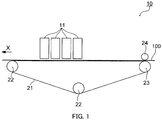
- FIG. 1 schematically illustrates one configuration example of an inkjet recording apparatus according to the present embodiment.
- inkjet recording apparatus 10 includes four inkjet head units 11 corresponding to respective colors of yellow, magenta, cyan and black, and a conveyance belt that continuously feeds cloth 100 as a recording medium.
- Arrow X in FIG. 1 indicates the conveyance direction of cloth 100.
- FIG. 2A schematically illustrates a configuration of inkjet head unit 11, in planar view
- FIG. 2B schematically illustrates a configuration of inkjet head unit 11, in side view
- FIG. 2C schematically illustrates a configuration of inkjet head unit 11, in front view.
- each inkjet head unit 11 includes a plurality of inkjet heads 111 disposed in two rows along the width direction of the cloth indicated by arrow Y, and blowout port 112 that blows out humidified air toward cloth 100.
- Each of inkjet heads 111 is secured on the conveyance belt.
- Inkjet heads 111 are disposed in Y direction so as to be mutually partially overlapped, and disposed without any gap as a whole.
- Blowout port 112 is a duct having an elongated rectangular opening that is expanded from the center in Y direction along Y direction, and corresponds to a humidification apparatus.
- Blowout port 112 is disposed upstream of inkjet heads 111 in X direction, and expanded to a region in which blowout port 112 is at least overlapped with all inkjet heads 111 in Y direction.
- Each inkjet head 111 includes, for example, an ink chamber, a pressure chamber and a nozzle (not illustrated), and is connected to an ink tank that accommodates ink of each color.
- Blowout port 112 is connected to, for example, a humidifier not illustrated.
- the conveyance belt includes, as illustrated in FIG. 1 , endless adhesion belt 21, support roll 22 and conveyance roll 23 that support adhesion belt 21, and nip roll 24 disposed at a position where nip roll 24 and conveyance roll 23 sandwich adhesion belt 21.
- Adhesion belt 21 has adhesiveness on a surface on which cloth 100 is placed.
- Conveyance roll 23 is configured so as to be rotatably driven, and support roll 22 is rotatably disposed.
- nip roll 24 is disposed to be able to approach to and separate from conveyance roll 23.
- cloth 100 is continuously conveyed in X direction.
- cloth 100 is subjected in advance to pretreatment by coating of a pretreatment liquid, drying of the liquid, and the like.
- humidified air at 25°C and 70 RH% for example, is fed at 2 m/sec to cloth 100 through blowout port 112 of inkjet head unit 11 located more upstream.
- the humidified air is fed to thereby allow the surface of cloth 100 to be wetted to the same degree as in landing of ink droplets.
- First ink is then ejected from inkjet head 111 to a portion wetted of cloth 100.
- the same humidification, and second and subsequent ink ejections are also performed by inkjet heads 111 located more downstream.
- FIG. 3A schematically illustrates a mode where a first ink penetrates into a cloth
- FIG. 3B schematically illustrates a mode where, when a second ink is further ejected to a cloth which is humidified immediately before ejection of the first ink and to which the first ink is ejected, the second ink penetrates into the cloth
- FIG. 3C schematically illustrates a mode where, when a second ink is further ejected to a cloth which is not humidified before ejection of the first ink and to which the first ink is ejected, the second ink penetrates into the cloth.
- ink for example, cyan ink
- the ink penetrates into the cloth around positions where ink droplets are landed, with being spread in both of the direction along the surface of the cloth and the depth direction, as illustrated in FIG. 3A .
- the cloth is here dry, the ink penetrates into the cloth, with being absorbed to a water-soluble polymer attached to a fiber, in the pretreatment agent.
- the cloth is wet, the ink penetrates into the cloth in which the water-soluble polymer is swollen, and therefore the ink less penetrates in the thickness direction of the cloth and is more easily spread in the direction along the surface than the ink in the case where the cloth is dry.
- the cyan ink When the cloth is wetted in advance, in ejection of the cyan ink, to the same degree as the degree of wetting by landing of droplets of the ink, the cyan ink is spread in the same manner as the spreading in a cloth after ink ejection, and thus penetrates into the above cloth.
- the yellow ink penetrates into the cloth in the same manner as the cyan ink, as illustrated in FIG. 3B .
- the reason for this is considered because the state of the cloth portion in penetration of the cyan ink (for example, the degree of swelling of the water-soluble polymer) is substantially the same as the state of the cloth portion in penetration of the yellow ink.
- the yellow ink penetrates into a portion that is substantially the same as the cloth portion into which the cyan ink penetrates, to thereby form a green dot.
- the yellow ink penetrates into a wider portion than the portion into which the cyan ink penetrates, in the direction along the surface of the cloth, namely, the outside of the green dot, as illustrated in FIG. 3C . Therefore, edging of the yellow ink ejected later is formed on an image formed on the surface of the cloth (arrow in FIG. 3C ).
- both of the cyan ink and the yellow ink penetrate into the cloth in a wider region from the landing positions.
- the volume of ink droplets is limited, and therefore the inks may further penetrate in the direction along the surface of the cloth and in the thickness direction to thereby decrease the hues of the inks, resulting in no sufficient development on the surface of the cloth.
- the inks may be thus excessively spread to cause the boundary between different hues in an image to be formed on the surface of the cloth to be more blurred, thereby resulting in a further reduction in definition of the image.
- the inkjet head is moved from side to side (for example, in Y direction in FIG. 2A ) as compared with that in a scanning inkjet recording apparatus in which an inkjet head ejects ink with several times of scanning, and the amount of ink ejection per unit time is generally smaller than that in a one-pass inkjet recording apparatus. Therefore, ink is easily dried to easily stabilize the humidity on the recording medium in image forming by the scanning inkjet recording apparatus, as compared with image forming by the one-pass inkjet recording apparatus. Accordingly, the environment around the recording medium is not significantly changed between first droplet ejection and second droplet ejection, and the degrees of spreading of the inks landed on the recording medium are not substantially affected
- an image is usually formed in an interleaved manner in the scanning inkjet recording apparatus. Therefore, for example, a case where the cyan ink is landed at a position where the yellow ink is landed and a case where the yellow ink is landed at a position where the cyan ink is landed are generated randomly and at the same degree in the entire recording medium (cloth). Accordingly, even if the dot diameters of the yellow ink and the cyan ink landed at the same position are different, portions different in the landing order are present randomly, but almost uniformly in an area of the recording medium, in which an image is formed, to thereby form an image small in a feeling of strangeness as a whole.
- the inkjet head is not moved in image forming by the one-pass inkjet recording apparatus, and the amount of ink ejection per unit time is generally larger than that in the scanning inkjet recording apparatus. Therefore, the humidity near the inkjet tends to become higher. Accordingly, the environment around the recording medium significantly differs between first droplet ejection and second droplet ejection, also resulting in the difference in the degree of spreading between the inks landed on the recording medium.
- the inkjet head is secured and the ink ejection order is usually fixed in the one-pass inkjet recording apparatus (e.g., the yellow ink is first ejected, and the cyan ink is then ejected). Therefore, even a slight difference is generated between the dot diameter of the yellow ink and the dot diameter of the cyan ink to thereby cause a feeling of strangeness due to the difference to be increased in the entire image formed, resulting in forming of an image large in a feeling of strangeness.
- the inkjet recording method is an inkjet recording method including ejecting two or more inks each containing an aqueous medium and a colorant to the surface of a recording medium having absorbability of the aqueous medium by one scanning of an inkjet head over the recording medium, to thereby form an image, wherein the recording medium is a cloth or a non-woven fabric, and the inkjet recording method includes humidifying the surface of the recording medium before ejection of the inks to the recording medium. Therefore, a definite image can be formed even in the case of forming of an image on a recording medium having absorbability by a one-pass inkjet recording method.
- the method inkjet recording method, it is much more effective from the viewpoint of forming of a high-definition image on the cloth at high productivity that the method can be applied to textile printing and the recording medium includes, on the surface thereof, a pretreatment agent that prevents blur of the inks.
- the inks each contain glycols and the content of the glycols in each of the inks is 15 to 60mass%. It is much more effective from the above viewpoints that the content of the glycols in each of the inks is 30 to 60mass%.
- the inkjet recording apparatus is a one-pass inkjet recording apparatus including an inkjet that ejects ink with being relatively moved in one direction to a recording medium, to form a predetermined image by one scanning to the recording medium, and a conveyance mechanism that holds the recording medium to relatively move the inkjet in one direction to the recording medium, wherein the recording medium is a cloth or a non-woven fabric, and the inkjet recording apparatus further includes a humidification apparatus that humidifies the front portion of the surface of the recording medium in the scanning direction of the inkjet head, of the recording medium. Therefore, a definite image can be formed even in the case of forming of an image on a recording medium having absorbability by a one-pass inkjet recording method.
- the inkjet head includes a plurality of nozzle groups that eject inks of a plurality of colors, each of the nozzle groups ejects ink of a different color, and a plurality of the humidification apparatuses are disposed corresponding to the respective nozzle groups and are disposed in front in the scanning direction of the nozzle groups.
- the inkjet recording apparatus here includes a humidification apparatus for each inkjet head, it may include a humidification apparatus for each inkjet head unit.
- the inkjet recording apparatus includes inkjet head units 41, and blowout ports 412 for individual inkjet head units 41, the ports disposed upstream in the movement direction of the cloth (opposite in the case of X direction), as illustrated in FIG. 4 .
- Inkjet head units 41 are the same as inkjet head units 11 except for having no blowout port 112, and blowout ports 412 are each the same as blowout port 112 except for being disposed outside of the inkjet head units.
- the inkjet recording apparatus illustrated in FIG. 4 is preferable because of exerting the same effect as that in the inkjet recording apparatus illustrated in FIG. 1 and also being more easily altered so that the existing inkjet recording apparatus for textile printing can be applied to the present invention.
- the inkjet recording apparatus may include one humidification apparatus to be disposed upstream of a plurality of inkjet heads.
- the humidification apparatus in the inkjet recording apparatus may be one other than the blowout port, for example, a spray apparatus that feeds mist to the cloth.
- the cloth in the inkjet recording apparatus, while the cloth is moved relative to the inkjet head in X direction, it may be moved relative to the inkjet head in the direction opposite to X direction. In such a case, the cloth may be secured or may be moved in synchronization with movement of the inkjet head in X direction or the opposite direction thereto.
- DISPERBYK-190 produced by BYK, comb-like block polymer dispersant, solid content: 40mass%
- a dispersant was added to 60 parts by weight of ion exchange water, and 5 parts by weight of dipropylene glycol propyl ether was mixed therewith.
- C.I. Disperse Blue-60 as a disperse dye was added to the solution and pre-mixed, the resultant was dispersed by a sand grinder filled with 0.5-mm zirconia beads at a volume fraction of 50%, to provide dye dispersion liquid A-1 having a dye solid content of 20mass%.
- the Z average particle size of a disperse particle of dye dispersion liquid A-1 obtained was measured by a dynamic light scattering particle size distribution meter Zeta Sizer Nano S (manufactured by Malvern Instruments Ltd.), and was 0.15 ⁇ m.
- dye dispersion liquid A-1 Twenty five parts by weight of dye dispersion liquid A-1 was added to a mixed liquid in which 40 parts by weight of ethylene glycol, 7 parts by weight of glycerin, 0.2 parts by weight of PROXEL GXL (antifungal agent produced by LONZA Japan) and 0.2 parts by weight of KF-351A (surfactant produced by Shin-Etsu Chemical Co., Ltd.) were added to 27.6 parts by weight of ion exchange water, and the resultant was stirred and thereafter filtered by a filter of 1 ⁇ m to provide cyan ink 1.
- a mixed liquid 40 parts by weight of ethylene glycol, 7 parts by weight of glycerin, 0.2 parts by weight of PROXEL GXL (antifungal agent produced by LONZA Japan) and 0.2 parts by weight of KF-351A (surfactant produced by Shin-Etsu Chemical Co., Ltd.) were added to 27.6 parts by weight of ion exchange water, and the resultant was stirred and
- cyan ink 2 was obtained in the same manner as production of cyan ink 1 except that the amount of ion exchange water to be added and the amount of ethylene glycol to be added were changed to 57.6 parts by weight and 10 parts by weight, respectively.
- Dye dispersion liquid A-2 was obtained in the same manner as production of dye dispersion liquid A-1 except that the disperse dye was changed to C.I. Disperse Yellow-114.
- the Z average particle size of a disperse particle of dye dispersion liquid A-2 obtained was 0.17 ⁇ m.
- Yellow ink 1 was obtained in the same manner as in production of the cyan ink except that dye dispersion liquid A-1 was changed to dye dispersion liquid A-2.
- yellow ink 2 was obtained in the same manner as in production of yellow ink 1 except that the amount of ion exchange water to be added and the amount of ethylene glycol to be added were changed to 57.6 parts by weight and 10 parts by weight, respectively.
- a polyester cloth in which the fineness of a thread was 50 d was immersed in an aqueous carboxymethyl cellulose solution as a pretreatment, and squeezed and dried.
- Blowout ports for feeding humidified air were disposed upstream, in the feeding direction of the cloth, of inkjet heads of respective colors of a commercially available inkjet recording apparatus for one-pass textile printing so as to be overlapped with the inkjet heads in the width direction of the cloth, to prepare a one-pass tester illustrated in FIG. 1 .
- a fine line (cyan: 75%, yellow: 75%) of 0.5 mm in width was printed on the cloth by use of cyan ink 1 and yellow ink 1 described above together with the tester, preliminarily dried, thereafter subjected to HT steam treatment at 175°C for 10 minutes, thereafter washed with water, subjected to reduction washing with an aqueous 0.2% hydrosulfite solution at 80°C, and furthermore thereafter sufficiently washed with water and dried.
- the color blur of the fine line to be formed was observed visually and by an optical microscope at 100-fold magnification, and evaluated according to the following criteria.
- the "color blur” means the difference in blur between cyan and yellow colors.
- a fine line and a rectangular image were formed on the cloth in the same manner as in Example 1 except that no humidification of the cloth before ink ejection was performed, and the fine line and the image were evaluated.
- the rectangular image in Comparative Example 1 was a reference image in the sensory test of the image density.
- a fine line and a rectangular image were formed on the cloth in the same manner as in Example 1 except that a liquid composition (penetrant) was attached to the cloth as described in PTL 1 instead of humidification of the cloth before ink ejection, and the fine line and the image were evaluated.
- a liquid composition penetrant
- Blowout ports for feeding humidified air were disposed at the tips (namely, both ends of each inkjet head), in the scanning direction (direction across the feeding direction of the cloth), of inkjet heads of respective colors of a commercially available inkjet recording apparatus for scanning textile printing so as to be overlapped with the inkjet heads in the scanning direction, to prepare a scanning comparative tester.
- the "scanning” means an inkjet recording method in which ink is ejected to a cloth with the cloth being conveyed and an inkjet head being reciprocated in the direction across the conveyance direction of the cloth.
- a fine line and a rectangular image were formed on the cloth in the same manner as in Example 1 except that the comparative tester was used, and the fine line and the image were evaluated.
- a fine line and a rectangular image were formed on the cloth in the same manner as in Comparative Example 3 except that no humidification of the cloth before ink ejection was performed, and the fine line and the image were evaluated.
- Example 1 The evaluation results in Example 1 and Comparative Examples 1 to 4 are shown in Table 1.
- Table 1 Recording system Humidification Color blur Image density Example 1 One-pass Humidified air A A Example 2 One-pass Humidified air B A Comparative Example 1 One-pass None C A Comparative Example 2 One-pass Penetrant A C Comparative Example 3 Scanning Humidified air A A Comparative Example 4 Scanning None A A
- Example 2 color blur was more suppressed in Example 1 as compared with Example 2. From the foregoing, the concentration of glycols in each ink is more effectively 15mass% or more from the viewpoint of suppression of color blur.
- the present invention can allow a high-definition image to be formed even on a recording medium having absorbability of an aqueous medium by a one-pass system high in productivity. Accordingly, the present invention is expected to contribute to further development of high-speed and high-definition inkjet textile printing.
Abstract
Description
- The present invention relates to an inkjet recording method and an inkjet recording apparatus.
- In an inkjet recording method, ink is ejected from an inkjet head to a recording medium, and droplets of the ink are collected to thereby form an image. The inkjet recording method is also utilized for textile printing. In the textile printing, as the ink, an ink containing an aqueous medium and a colorant is usually used. In the textile printing, the recording medium is usually a cloth. When an image is formed by the ink on the surface of the cloth according to the textile printing by the inkjet recording method, a cloth subjected to a pretreatment with a pretreatment agent for suppression of ink blur is used for the cloth. The cloth pretreated with a pretreatment agent is usually dried and then used, and therefore has the property of absorbing the aqueous medium of the ink.
- On the other hand, a one-pass inkjet recording method is known as a commercially advantageous inkjet recording method. In the one-pass inkjet recording method, at least one ink is ejected from an inkjet head onto the surface of a recording medium by one scanning of the inkjet head over the recording medium to thereby form an image.
- If inks of a plurality of colors are superposed on the recording medium having absorbability, such as a cloth, by the one-pass inkjet recording method, edging of the color of an ink ejected later may be formed on an image formed, causing the image to be lack in definition.
- As a technique for suppression of blur due to ink soaking into the cloth in the textile printing by the inkjet recording method, penetration of a penetrant is known (e.g., see PTLS 1 to 3). In such an inkjet recording method, however, a cloth is sufficiently wetted by the penetrant, and therefore ink may be more spread in the cloth to cause the image density on the surface of the cloth to be insufficient or to result in an image lack in definition.
-
- PTL 1
Japanese Patent Application Laid-Open No. 2011-179130 - PTL2
Japanese Patent Application Laid-Open No. 2013-007126 - PTL3
Japanese Patent Application Laid-Open No. 2012-096513 - An object of the present invention is to form a definite image even in the case of forming of an image on a recording medium having absorbability by a one-pass inkjet recording method.
- The present invention also relates to the following inkjet recording method.
- [1] A one-pass inkjet recording method including: ejecting two or more inks each containing an aqueous medium and a colorant to a surface of a recording medium having absorbability of the aqueous medium by one scanning of an inkjet head over the recording medium to thereby form an image, in which the recording medium is a cloth or a non-woven fabric, and the inkjet recording method comprises humidifying the surface of the recording medium before ejection of the inks to the recording medium.
- [2] The inkjet recording method according to [1], in which the surface is humidified by air having a relative humidity of 50 to 80%.
- [3] The inkjet recording method according to [1] or [2], in which the surface is humidified before ejection of each one of the inks.
- [4] The inkjet recording method according to any one of claims [1] to [3], in which the inks each contain glycols, and a content of the glycols in each of the inks is 15 to 60mass%.
The present invention also relates to the following inkjet recording apparatus. - [5] A one-pass inkjet recording apparatus including an inkjet that ejects ink, with being relatively moved in one direction to a recording medium, to form a predetermined image by one scanning to the recording medium, and a conveyance mechanism that holds the recording medium to relatively move the inkjet in one direction to the recording medium, in which the recording medium is a cloth or a non-woven fabric, and the inkjet recording apparatus further includes a humidification apparatus for humidifying a front portion of a surface of the recording medium in a scanning direction of the inkjet head, of the recording medium.
- [6] The inkjet recording apparatus according to [5], in which the inkjet head includes a plurality of nozzle groups for ejecting inks of a plurality of colors, each of the nozzle groups ejects ink of a different color, and a plurality of the humidification apparatuses are disposed corresponding to the respective nozzle groups and are disposed in front in the scanning direction of the nozzle groups.
- [7] The inkjet recording apparatus according to [5] or [6], in which the humidification apparatus includes a nozzle for feeding air having a relative humidity of 50 to 80% to a surface of the recording medium.
- According to the present invention, the surface of the recording medium is wetted, before ink arrival at the surface of the recording medium, to the same degree of wetting as in landing of ink droplets, and therefore ink droplets first landed on the recording medium and ink droplets landed thereon later are spread on the recording medium in the substantially same manner. Accordingly, no edging of the color of an ink ejected later occurs around an image formed, and therefore a definite image can be formed in the case of forming of an image on a recording medium having absorbability by a one-pass inkjet recording method.
-
-
FIG. 1 schematically illustrates one configuration example of an inkjet recording apparatus according to one embodiment of the present invention; -
FIG. 2A schematically illustrates a configuration of an inkjet head unit in the present embodiment in planar view,FIG. 2B schematically illustrates a configuration of the inkjet head unit in side view, andFIG. 2C schematically illustrates a configuration of the inkjet head unit in front view; -
FIG. 3A schematically illustrates a mode where a first ink penetrates into a cloth,FIG. 3B schematically illustrates a mode where a second ink penetrates into the cloth, when the second ink is further ejected to a cloth which is humidified immediately before ejection of the first ink and to which the first ink is ejected, andFIG. 3C schematically illustrates a mode where a second ink penetrates into the cloth, when the second ink is further ejected to a cloth which is not humidified before ejection of the first ink and to which the first ink is ejected; and -
FIG. 4 schematically illustrates another configuration example of the inkjet recording apparatus according to one embodiment of the present invention. - One embodiment of the present invention is described below.
- An inkjet recording method according to the present embodiment is a so-called one-pass inkjet recording method including ejecting two or more inks to the surface of a recording medium by one scanning of an inkjet head over the recording medium to thereby form an image.
- The inks each contain an aqueous medium and a colorant. The inks are two or more inks and are usually inks of different colors, but may be inks of the same color. The inks may be any number of inks as long as the number of inks is two or more and a predetermined appearance is obtained by superposing.
- The aqueous medium is a liquid containing water as a main component and is water or an aqueous solution. Examples of the solute of the aqueous medium include a salt and a water-soluble organic solvent.
- The content of the water-soluble organic solvent in each of the inks is preferably 15 to 70mass%, more preferably 30 to 60mass% from the viewpoints of dissolution of various components in each of the inks and drying property of the inks. The content is preferably 15mass% or more from the viewpoints that liquid properties such as ink viscosity are adjusted and a surfactant is dissolved. If the content is more than 70mass%, the inks may be deteriorated in drying property to cause a cloth after printing not to be dried, making it impossible to superpose or roll up printed products before a heat treatment (color development).
- Examples of the water-soluble organic solvent include a polyhydric alcohol, an amine, a monohydric alcohol, an alkyl ether of a polyhydric alcohol, 2,2'-thiodiethanol, an amide, a heterocyclic compound, and acetonitrile.
- Examples of the polyhydric alcohol include 1,6-hexanediol, 1,2-hexanediol, 1,5-pentanediol, 1,2-pentanediol, 2,2-dimethyl-1,3-propanediol, 2-methyl-2,4-pentanediol, 3-methyl-1,5-pentanediol, 3-methyl-1,3-butanediol, 2-methyl-1,3-propanediol and glycols.
- Examples of the glycols include ethylene glycol, glycerin, 2-ethyl-2-(hydroxymethyl)-1,3-propanediol, tetraethylene glycol, triethylene glycol, tripropylene glycol, 1,2,4-butanetriol, diethylene glycol, propylene glycol, dipropylene glycol and butylene glycol.
- The content of the glycols in each of the inks is preferably 15 to 60mass%, more preferably 30 to 60mass% not only from the viewpoint of the above reasons, but also from the viewpoint that a water-soluble polymer of the cloth is inhibited from being excessively swollen, to allow an ink to be ejected later to easily penetrate into the cloth, resulting in forming of a higher-definition image.
- Examples of the amine include ethanolamine and 2-(dimethylamino)ethanol.
- Examples of the monohydric alcohol include methanol, ethanol and butanol.
- Examples of the alkyl ether of polyhydric alcohol include diethylene glycol monomethyl ether, diethylene glycol monobutyl ether, triethylene glycol monomethyl ether, triethylene glycol monobutyl ether, ethylene glycol monomethyl ether, ethylene glycol monobutyl ether, propylene glycol monomethyl ether, propylene glycol monobutyl ether and dipropylene glycol monomethyl ether.
- Examples of the amide include N,N-dimethylformamide.
- Examples of the heterocyclic compound include 2-pyrrolidone.
- The colorant may be used singly or in combinations of two or more. Examples of the colorant include a water-soluble dye, a disperse dye, pigment, a reactive dye, an acid dye and a direct dye. As the colorant, for example, any of various colorants described in "Dyeing Note 21st Edition" (Shikisensha Co., Ltd.) can be used.
- Examples of the disperse dye include C. I. Disperse
Yellows Oranges Reds Violets 1, 4, 8, 23, 26, 27, 28, 31, 33, 35, 36, 38, 40, 43, 46, 48, 50, 51, 52, 56, 57, 59, 61, 63, 69, and 77; C. I. Disperse Green 9; C. I. Disperse Browns 1, 2, 4, 9, 13, and 19; C. I. DisperseBlues 3, 7, 9, 14, 16, 19, 20, 26, 27, 35, 43, 44, 54, 55, 56, 58, 60, 62, 64, 71, 72, 73, 75, 79, 81, 82, 83, 87, 91, 93, 94, 95, 96, 102, 106, 108, 112, 113, 115, 118, 120, 122, 125, 128, 130, 139, 141, 142, 143, 146, 148, 149, 153, 154, 158, 165, 167, 171, 173, 174, 176, 181, 183, 185, 186, 187, 189, 197, 198, 200, 201, 205, 207, 211, 214, 224, 225, 257, 259, 267, 268, 270, 284, 285, 287, 288, 291, 293, 295, 297, 301, 315, 330, and 333; and, C. I. DisperseBlacks - Examples of the pigment include carbon black; C. I. Pigment Yellows 1, 3, 12, 13, 14, 16, 17, 43, 55, 74, 81, 83, 109, 110, and 128; C. I. Pigment Oranges 13, 16, 34, and 43; C. I.
Pigment Reds Pigment Violets 19 and 23; C. I. Pigment Blues 15, 15:1, 15:3, 15:5, and 29; C. I. Pigment Greens 7 and 8; C. I.Pigment Brown 22; C. I. Pigment Blacks 1 and 7; and, C. I. Pigment White 6. - Examples of the reactive dye include C. I.
Reactive Yellows Reactive Oranges 1, 4, 5, 7, 11, 12, 13, 15, 16, 20, 30, 35, 56, 64, 67, 69, 70, 72, 74, 82, 84, 86, 87, 91, 92, 93, 95, and 107; C. I. Reactive Reds 2, 3, 3:1, 5, 8, 11, 21, 22, 23, 24, 28, 29, 31, 33, 35, 43, 45, 49, 55, 56, 58, 65, 66, 78, 83, 84, 106, 111, 112, 113, 114, 116, 120, 123, 124, 128, 130, 136, 141, 147, 158, 159, 171, 174, 180, 183, 184, 187, 190, 193, 194, 195, 198, 218, 220, 222, 223, 228, and 235; C. I.Reactive Violets Reactive Blues Reactive Greens 8, 12, 15, 19, and 21; C. I.Reactive Browns - Examples of the acid dye include C. I.
Acid Yellows Acid Oranges Acid Violets 17, 19, 21, 42, 43, 47, 48, 49, 54, 66, 78, 90, 97, 102, 109, and 126; C. I.Acid Blues 1, 7, 9, 15, 23, 25, 40, 61:1, 62, 72, 74, 80, 83, 90, 92, 103, 104, 112, 113, 114, 120, 127, 127:1, 128, 129, 138, 140, 142, 156, 158, 171, 182, 185, 193, 199, 201, 203, 204, 205, 207, 209, 220, 221, 224, 225, 229, 230, 239, 258, 260, 264, 277:1, 278, 279, 280, 284, 290, 296, 298, 300, 317, 324, 333, 335, 338, 342, and 350; C. I. Acid Greens 9, 12, 16, 19, 20, 25, 27, 28, 40, 43, 56, 73, 81, 84, 104, 108, and 109; C. I. Acid Browns 2, 4, 13, 14, 19, 28, 44, 123, 224, 226, 227, 248, 282, 283, 289, 294, 297, 298, 301, 355, 357, and 413; and, C. I.Acid Blacks 1, 2, 3, 24, 24:1, 26, 31, 50, 52, 52:1, 58, 60, 63, 63S, 107, 109, 112, 119, 132, 140, 155, 172, 187, 188, 194, 207, and 222. - Examples of the direct dye include C. I.
Direct Yellows Direct Reds Direct Blacks - The content of the colorant in the ink is preferably 0.1 to 20mass%, more preferably 0.2 to 13mass%.
- The Z average particle size of the pigment or the disperse dye is preferably 300 nm or less, or the maximum particle size of the pigment or the disperse dye is preferably 900 nm or less. If the Z average particle size or the maximum particle size exceeds the above range, clogging easily occurs in inkjet textile printing where the ink is launched from a fine nozzle, and the ink cannot be stably launched for a long period of time in some cases.
- The Z average particle size or the maximum particle size can be measured by use of a commercially available particle size measuring machine such as Zeta Sizer Nano S manufactured by Malvern Instruments Ltd. according to a light scattering method, an electrophoresis method, a laser Doppler method, or the like. In addition, the Z average particle size or the maximum particle size can be adjusted by a dispersion treatment of the pigment or the disperse dye with a commercially available dispersant by a bead mill or the like, classification of the pigment or the disperse dye, mixing of classified products, or the like.
- The inks may each further contain any component other than the above components as long as the effects of the present embodiment are achieved. For example, the inks may each further contain a surfactant from the viewpoints that the surface tension of the inks is adjusted and dispersion of the colorant is more stabilized.
- The surfactant may be one or more surfactants. The surfactant may be any of cationic, anionic, amphoteric and nonionic surfactants.
- Examples of the cationic surfactant include an aliphatic amine salt, an aliphatic quaternary ammonium salt, a benzalkonium salt, benzethonium chloride, a pyridinium salt and an imidazolinium salt.
- Examples of the anionic surfactant include fatty acid soap, an N-acyl-N-methylglycine salt, an N-acyl-N-methyl-β-alanine salt, N-acylglutamate, alkyl ether carboxylate, acylated peptide, alkyl sulfonate, alkylbenzene sulfonate, alkylnaphthalene sulfonate, dialkyl sulfosccinate, alkyl sulfoacetate, α-olefin sulfonate, N-acylmethyltaurine, sulfated oil, higher alcohol sulfate, higher secondary alcohol sulfate, alkyl ether sulfate, higher secondary alcohol ethoxysulfate, polyoxyethylene alkyl phenyl ether sulfate, monoglysulfate, fatty acid alkyloamide sulfate, alkyl ether phosphate and alkyl phosphate.
- Examples of the amphoteric surfactant include a carboxybetaine surfactant, a sulfobetaine surfactant, an amino carboxylic acid salt, and imidazolinium betaine.
- Examples of the non-ionic surfactant include polyoxyethylene alkyl ether, polyoxyethylene secondary alcohol ether, polyoxyethylene alkyl phenyl ether (for example, Emulgen 911), polyoxyethylene sterol ether, a polyoxyethylene lanolin derivative, polyoxyethylene polyoxypropylene alkyl ether (for example, Newpol PE-62), polyoxyethyleneglycerin fatty acid ester, polyoxyethylene castor oil, hydrogenated castor oil, polyoxyethylene sorbitan fatty acid ester, polyoxyethylene sorbitol fatty acid ester, polyethylene glycol fatty acid ester, fatty acid monoglyceride, polyglycerin fatty acid ester, sorbitan fatty acid ester, propylene glycol fatty acid ester, sucrose fatty acid ester, fatty acid alkanolamide, polyoxyethylene fatty acid amide, polyoxyethylene alkyl amine, alkyl amine oxide, acetylene glycol and acetylene alcohol. "Emulgen" is a registered trademark of Kao Corporation, and "Newpol" is a registered trademark of Sanyo Chemical Industries, Ltd.
- The surfactant is preferably a non-ionic surfactant or an anionic surfactant, more preferably sodium dodecylbenzenesulfonate, sodium 2-ethylhexylsulfosuccinate, sodium alkylnaphthalenesulfonate, a phenol-ethylene oxide adduct, or an acetylenediol-ethylene oxide adduct.
- The content of the surfactant in the ink can be appropriately determined from the viewpoints of enhancement in dispersibility of a colorant and adjustment of the surface tension of the ink, and is, for example, 0.05 to 2mass%.
- In addition, the inks may each contain a preservative agent or an antifungal agent in terms of storage stability of the inks. Examples of the preservative agent or the antifungal agent include an aromatic halogen compound (for example, Preventol CMK), methylene dithiocyanate, a halogenated nitrogen-containing sulfur compound, and 1,2-benzisothiazolin-3-one (for example, PROXEL GXL). "Preventol" is a registered trademark of Lanxess AG, and "PROXEL" is a registered trademark of Arch Chemicals Inc.
- The recording medium has the property of absorbing the aqueous medium (absorbability of the aqueous medium). Such absorbability refers to the following property: an aqueous medium attached to a recording medium penetrates into the recording medium with being spread in both of the direction along the surface of the recording medium and the thickness direction of the recording medium. The aqueous medium to which the recording medium exhibits absorbability may be the same as or different from the aqueous medium in the inks.
- The recording medium can be selected from recording mediums that have the absorbability and that can be used in textile printing. The recording medium may be, for example, a sheet or a shaped article formed from a fiber, and such a fiber material is appropriately selected so that the effects of the present embodiment are achieved. The recording medium is, for example, a cloth or a non-woven fabric.
- The cloth is configured from, for example, a fiber that can be dyed by a reactive dye. Examples of such a cloth include cellulose fibers such as cotton, protein fibers such as silk, and blend fabrics of any of such fibers with rayon, polyurethane, polyester or an acrylic resin. The form of the cloth may be any of a woven fabric, a knitted fabric and a non-woven fabric. The fineness of a fiber constituting the cloth is preferably, for example, 10 to 100 d.
- The cloth preferably includes, on the surface of the cloth, a pretreatment agent that prevents blur of the inks, from the viewpoint of forming of a definite image. The pretreatment agent may be included in only a surface portion of the cloth (recording medium) in the thickness direction, or may be included in the entire of the cloth in the thickness direction. The pretreatment agent contains, for example, a water-soluble polymer compound, an alkaline agent and a hydrotropy agent.
- The water-soluble polymer compound is a polymer compound that can be uniformly dispersed and dissolved in water. Examples of the water-soluble polymer compound include natural gum such as guar gum and locust bean gum; starch; sodium alginate; seaweeds such as funori; vegetable skins such as pectin acid; cellulose derivatives such as methyl cellulose, ethyl cellulose, hydroxyethyl cellulose and carboxymethyl cellulose; processed starch such as roasted starch, alpha-starch, carboxymethyl starch, carboxyethyl starch and hydroxyethyl starch; processed natural gum such as shiratsu gum and roast bean gum; and synthetic pastes or emulsions such as an alginate derivative, polyvinyl alcohol and polyacrylic acid ester.
- The amount of the water-soluble polymer compound to be applied to the cloth is preferably 0.2 to 50mass%, more preferably 1 to 30mass% from the viewpoint that the water-soluble polymer compound is held in the cloth without any blur of the inks.
- Examples of the alkaline agent include alkali metal hydroxides such as sodium hydroxide and potassium hydroxide; amines such as mono-, di- and triethanolamines; alkali metal carbonates or bicarbonates such as sodium carbonate, potassium carbonate and sodium bicarbonate (sodium hydrogen carbonate); organic acid metal salts such as calcium acetate and barium acetate; ammonia and ammonium compounds; and compounds serving as an alkaline agent under steaming or dry heat, such as sodium trichloroacetate. The alkaline agent is more preferably sodium carbonate or sodium hydrogen carbonate.
- The amount of the alkaline agent to be applied to the cloth is preferably 0.1 to 10mass%, more preferably 0.5 to 5mass% from the viewpoint that the inks containing a reactive dye are allowed to dye in the cloth. The alkaline agent is preferably contained in the cloth in advance from the above viewpoint.
- The hydrotropy agent is used from the viewpoint of an increase in image density. Examples of the hydrotropy agent include urea; and alkyl ureas such as ethylene urea, dimethylurea, thiourea, monomethylthiourea and dimethylthiourea.
- The pretreatment agent may further contain any component other than the above components. Examples of the other component include a reduction inhibitor, a preservative agent and a chelating agent.
- Examples of the reduction inhibitor include sodium m-nitrobenzenesulfonate. Examples of the preservative agent include preservative agents exemplified as the preservative agent of the inks. Examples of the chelating agent include ethylenediamine tetraacetate, nitrilotriacetate, hexamethaphosphate, pyrophosphate and methaphosphate.
- The amount (pick-up rate) of the pretreatment agent to be applied, and the content of the water-soluble polymer compound in the pretreatment agent are appropriately selected depending on the kind of the cloth, for example.
- Examples of the method of applying the pretreatment agent to the cloth include a pad method, a coating method, a spray method and an inkjet method. The pretreatment agent applied to the cloth can be heated and dried by use of a known heating apparatus such as hot air, a hot plate or a heat roller. Examples of the cloth to which the pretreatment agent is applied include cloths having an ink reception layer, described in
Japanese Patent Application Laid-Open No. 62-53492 Japanese Examined Patent Application Publication No. 3-46589 - An inkjet recording method of the present embodiment includes humidifying the surface of the recording medium before ejection of the inks to the recording medium (humidification). The degree of humidification of the recording medium in the humidification can be appropriately determined with the upper limit thereof being the degree of wetting of the recording medium to be wetted by ink ejection, as long as the effects of the present invention are achieved. For example, the degree of wetting of the recording medium in the humidification may be very low, or may correspond to a degree at which the fiber in the recording medium is wetted by landing of ink droplets or a degree at which the water-soluble polymer compound in the pretreatment agent is swollen by landing of ink droplets. Thus, the degree of humidification of the recording medium may be at most the degree of wetting of the surface by ejection of the inks, and the humidification may allow the surface of the recording medium before landing of ink droplets to be wetted to the substantially same degree of wetting of the surface of the recording medium after landing of ink droplets.
- The humidification region in the thickness direction of the recording medium in the humidification can be appropriately determined as long as the effects of the present invention are achieved, and, for example, can be appropriately determined within a region including a region in which inks of ink droplets landed on the surface of the recording medium arrive (penetrate). The region is appropriately determined depending on the kinds of the inks as well as the kind and the thickness of the recording medium. Thus, the humidification allows at least the surface of the recording medium to exhibit wetting corresponding to the wetting by the aqueous medium due to landing of ink droplets, before landing of ink droplets.
- The humidification can be performed by feeding the aqueous medium to the surface of the recording medium. The aqueous medium may be the same as or different from the aqueous medium of each of the inks to be used. The aqueous medium in the humidification is fed to the surface of the recording medium, as a gas in which the humidity of humidified air or the like is adjusted, a fine particle of the aqueous medium, such as nano mist, or the like. In particular, humidified air is preferable from the viewpoints of uniformly humidifying the surface of the recording medium and being able to be produced easily and inexpensively.
- More specifically, when air humidified by an aqueous medium such as water (humidified air) is used in the humidification, the relative humidity of the humidified air may be so low to thereby cause wetting of the surface of the recording medium by landing of ink droplets to be insufficiently reproduced, and may be so high to thereby cause droplets due to dew condensation to be fed to the recording medium, resulting in excessive wetting of the surface of the recording medium. The relative humidity of the humidified air is preferably 50 to 80%, more preferably 55 to 75% from such viewpoints.
- In addition, the temperature of the humidified air may be so low to thereby cause the humidity of the humidified air to be insufficient, resulting in insufficient reproduction of wetting of the surface of the recording medium by landing of ink droplets, and may be so high to thereby cause drying of the surface of the recording medium properly wetted to be promoted, also resulting in insufficient reproduction of wetting of the surface of the recording medium by landing of ink droplets. The temperature of the humidified air is preferably 20 to 40°C, more preferably 20 to 30°C from such viewpoints.
- Furthermore, the volume of the humidified air may be so small to thereby cause wetting of the surface of the recording medium by landing of ink droplets to be insufficiently reproduced, and may be so large to thereby cause the shape of the surface of the recording medium and ink landing to be disordered, or cause the recording medium to be excessively wetted to promote penetration of the inks into the recording medium, resulting in an insufficient image density on the surface of the recording medium. The volume of the humidified air is preferably 0.2 to 5 m/sec, more preferably 0.5 to 3 m/sec from such viewpoints.
- While the humidification may be performed at one time before ejection of all the inks, the humidification is preferably separately performed with respect to each one of the inks from the viewpoint that ink droplets landed on the surface of the recording medium are spread uniformly with respect to all the inks to be ejected. The humidification can be performed with respect to ejection of each one of the inks by, for example, disposing a humidification apparatus that performs the humidification, with respect to each inkjet head of the inks. Examples of the apparatus include a nozzle that blows out humidified air or nano mist to the recording medium.
- In the inkjet recording method of the present embodiment, ink ejection is performed on the surface of the recording medium humidified in the humidification. The ink ejection is performed while the degree of wetting of the surface of the recording medium is substantially maintained. For example, the ink ejection is performed immediately after the humidification.
- The inkjet recording method of the present embodiment may also further include any operation other than the humidification as long as the effects of the present embodiment are achieved. Examples of the other operation include a pretreatment in which the recording medium is pretreated with the pretreatment agent; preliminary drying in which the recording medium after ink ejection is dried; color development in which the inks ejected to the recording medium are allowed to dye in the recording medium to develop the original hues of the inks; washing in which the recording medium after the color development is washed to remove the pretreatment agent and excessive inks from the recording medium; and drying in which the recording medium after the washing is dried. Such other operations can be performed by a known method in textile printing by the inkjet recording method.
- The inkjet recording method of the present embodiment can be performed by, for example, an apparatus in which a known one-pass inkjet recording apparatus is provided with the humidification apparatus.
FIG. 1 schematically illustrates one configuration example of an inkjet recording apparatus according to the present embodiment. As illustrated inFIG. 1 ,inkjet recording apparatus 10 includes fourinkjet head units 11 corresponding to respective colors of yellow, magenta, cyan and black, and a conveyance belt that continuously feedscloth 100 as a recording medium. Arrow X inFIG. 1 indicates the conveyance direction ofcloth 100. -
FIG. 2A schematically illustrates a configuration ofinkjet head unit 11, in planar view,FIG. 2B schematically illustrates a configuration ofinkjet head unit 11, in side view, andFIG. 2C schematically illustrates a configuration ofinkjet head unit 11, in front view. As illustrated inFIG. 2A to FIG. 2C , eachinkjet head unit 11 includes a plurality of inkjet heads 111 disposed in two rows along the width direction of the cloth indicated by arrow Y, andblowout port 112 that blows out humidified air towardcloth 100. Each of inkjet heads 111 is secured on the conveyance belt. - Inkjet heads 111 are disposed in Y direction so as to be mutually partially overlapped, and disposed without any gap as a whole.
Blowout port 112 is a duct having an elongated rectangular opening that is expanded from the center in Y direction along Y direction, and corresponds to a humidification apparatus.Blowout port 112 is disposed upstream of inkjet heads 111 in X direction, and expanded to a region in whichblowout port 112 is at least overlapped with all inkjet heads 111 in Y direction. Eachinkjet head 111 includes, for example, an ink chamber, a pressure chamber and a nozzle (not illustrated), and is connected to an ink tank that accommodates ink of each color.Blowout port 112 is connected to, for example, a humidifier not illustrated. - The conveyance belt includes, as illustrated in
FIG. 1 ,endless adhesion belt 21,support roll 22 and conveyance roll 23 that supportadhesion belt 21, and niproll 24 disposed at a position where niproll 24 and conveyance roll 23sandwich adhesion belt 21.Adhesion belt 21 has adhesiveness on a surface on whichcloth 100 is placed.Conveyance roll 23 is configured so as to be rotatably driven, andsupport roll 22 is rotatably disposed. In addition, niproll 24 is disposed to be able to approach to and separate fromconveyance roll 23. - When the conveyance belt is driven,
cloth 100 is continuously conveyed in X direction. Herein,cloth 100 is subjected in advance to pretreatment by coating of a pretreatment liquid, drying of the liquid, and the like. - Next, humidified air at 25°C and 70 RH%, for example, is fed at 2 m/sec to
cloth 100 throughblowout port 112 ofinkjet head unit 11 located more upstream. The humidified air is fed to thereby allow the surface ofcloth 100 to be wetted to the same degree as in landing of ink droplets. First ink is then ejected frominkjet head 111 to a portion wetted ofcloth 100. The same humidification, and second and subsequent ink ejections are also performed byinkjet heads 111 located more downstream. - Thus, all inks of predetermined colors are ejected to
cloth 100 by only one passing ofinkjet head unit 11, to thereby form a desired image on the surface ofcloth 100.Cloth 100 on which an image is formed as described above is subjected to the above respective preliminary heating, color development, washing and drying operations. - When an image is formed on a cloth by the one-pass inkjet recording method described above, a definite image is formed in which no edging of the color of an ink ejected later occurs. The reason for this is considered as follows.
-
FIG. 3A schematically illustrates a mode where a first ink penetrates into a cloth,FIG. 3B schematically illustrates a mode where, when a second ink is further ejected to a cloth which is humidified immediately before ejection of the first ink and to which the first ink is ejected, the second ink penetrates into the cloth, andFIG. 3C schematically illustrates a mode where, when a second ink is further ejected to a cloth which is not humidified before ejection of the first ink and to which the first ink is ejected, the second ink penetrates into the cloth. - When ink (for example, cyan ink) is ejected to a cloth, the ink penetrates into the cloth around positions where ink droplets are landed, with being spread in both of the direction along the surface of the cloth and the depth direction, as illustrated in
FIG. 3A . If the cloth is here dry, the ink penetrates into the cloth, with being absorbed to a water-soluble polymer attached to a fiber, in the pretreatment agent. If the cloth is wet, the ink penetrates into the cloth in which the water-soluble polymer is swollen, and therefore the ink less penetrates in the thickness direction of the cloth and is more easily spread in the direction along the surface than the ink in the case where the cloth is dry. - When the cloth is wetted in advance, in ejection of the cyan ink, to the same degree as the degree of wetting by landing of droplets of the ink, the cyan ink is spread in the same manner as the spreading in a cloth after ink ejection, and thus penetrates into the above cloth.
- In such a case, when a yellow ink is ejected to the same positions of the cloth next to the cyan ink, the yellow ink penetrates into the cloth in the same manner as the cyan ink, as illustrated in
FIG. 3B . The reason for this is considered because the state of the cloth portion in penetration of the cyan ink (for example, the degree of swelling of the water-soluble polymer) is substantially the same as the state of the cloth portion in penetration of the yellow ink. As a result, the yellow ink penetrates into a portion that is substantially the same as the cloth portion into which the cyan ink penetrates, to thereby form a green dot. - On the one hand, when the cloth is not wetted (is dry) as described above in ejection of the cyan ink, a yellow ink to be then ejected less penetrates into a cloth in which a water-soluble polymer is not swollen, than the cyan ink that penetrates into the cloth with the water-soluble polymer being swollen. The reason for this is considered because a passage into which the yellow ink penetrates is narrower than the passage for the cyan ink by a passage portion corresponding to the swelling fraction of the water-soluble polymer. As a result, the yellow ink penetrates into a wider portion than the portion into which the cyan ink penetrates, in the direction along the surface of the cloth, namely, the outside of the green dot, as illustrated in
FIG. 3C . Therefore, edging of the yellow ink ejected later is formed on an image formed on the surface of the cloth (arrow inFIG. 3C ). - On the other hand, when the cloth is excessively wetted in ejection of the cyan ink (e.g., is wet so as to include a liquid), both of the cyan ink and the yellow ink penetrate into the cloth in a wider region from the landing positions. The volume of ink droplets is limited, and therefore the inks may further penetrate in the direction along the surface of the cloth and in the thickness direction to thereby decrease the hues of the inks, resulting in no sufficient development on the surface of the cloth. In addition, the inks may be thus excessively spread to cause the boundary between different hues in an image to be formed on the surface of the cloth to be more blurred, thereby resulting in a further reduction in definition of the image.
- In the inkjet recording apparatus, the inkjet head is moved from side to side (for example, in Y direction in
FIG. 2A ) as compared with that in a scanning inkjet recording apparatus in which an inkjet head ejects ink with several times of scanning, and the amount of ink ejection per unit time is generally smaller than that in a one-pass inkjet recording apparatus. Therefore, ink is easily dried to easily stabilize the humidity on the recording medium in image forming by the scanning inkjet recording apparatus, as compared with image forming by the one-pass inkjet recording apparatus. Accordingly, the environment around the recording medium is not significantly changed between first droplet ejection and second droplet ejection, and the degrees of spreading of the inks landed on the recording medium are not substantially affected - In addition, an image is usually formed in an interleaved manner in the scanning inkjet recording apparatus. Therefore, for example, a case where the cyan ink is landed at a position where the yellow ink is landed and a case where the yellow ink is landed at a position where the cyan ink is landed are generated randomly and at the same degree in the entire recording medium (cloth). Accordingly, even if the dot diameters of the yellow ink and the cyan ink landed at the same position are different, portions different in the landing order are present randomly, but almost uniformly in an area of the recording medium, in which an image is formed, to thereby form an image small in a feeling of strangeness as a whole.
- On the contrary, the inkjet head is not moved in image forming by the one-pass inkjet recording apparatus, and the amount of ink ejection per unit time is generally larger than that in the scanning inkjet recording apparatus. Therefore, the humidity near the inkjet tends to become higher. Accordingly, the environment around the recording medium significantly differs between first droplet ejection and second droplet ejection, also resulting in the difference in the degree of spreading between the inks landed on the recording medium.
- In addition, the inkjet head is secured and the ink ejection order is usually fixed in the one-pass inkjet recording apparatus (e.g., the yellow ink is first ejected, and the cyan ink is then ejected). Therefore, even a slight difference is generated between the dot diameter of the yellow ink and the dot diameter of the cyan ink to thereby cause a feeling of strangeness due to the difference to be increased in the entire image formed, resulting in forming of an image large in a feeling of strangeness.
- These are special problems about image forming by the one-pass inkjet recording apparatus, and the special problems can be solved by the present invention because substantially no difference in the dot diameter due to the landing order occurs even in image forming by the one-pass inkjet recording apparatus.
- As is clear from the above description, the inkjet recording method according to the present embodiment is an inkjet recording method including ejecting two or more inks each containing an aqueous medium and a colorant to the surface of a recording medium having absorbability of the aqueous medium by one scanning of an inkjet head over the recording medium, to thereby form an image, wherein the recording medium is a cloth or a non-woven fabric, and the inkjet recording method includes humidifying the surface of the recording medium before ejection of the inks to the recording medium. Therefore, a definite image can be formed even in the case of forming of an image on a recording medium having absorbability by a one-pass inkjet recording method.
- In addition, in the humidification, it is much more effective from the viewpoint of a suitable adjustment of the degree of wetting of the recording medium that the surface is humidified by air having a relative humidity of 50 to 80%.
- In addition, in the humidification, it is much more effective from the viewpoint of uniforming of the degrees of penetration of the respective inks into the recording medium for forming of a higher-definition image that the surface is humidified before ejection of each one of the inks.
- In addition, in the inkjet recording method, it is much more effective from the viewpoint of forming of a high-definition image on the cloth at high productivity that the method can be applied to textile printing and the recording medium includes, on the surface thereof, a pretreatment agent that prevents blur of the inks.
- In addition, it is much more effective from the viewpoints of suppression of excessive swelling of the water-soluble polymer in the cloth for easy penetration of an ink to be ejected later into the cloth and of consequent forming of a higher-definition image that the inks each contain glycols and the content of the glycols in each of the inks is 15 to 60mass%. It is much more effective from the above viewpoints that the content of the glycols in each of the inks is 30 to 60mass%.
- In addition, the inkjet recording apparatus according to the present embodiment is a one-pass inkjet recording apparatus including an inkjet that ejects ink with being relatively moved in one direction to a recording medium, to form a predetermined image by one scanning to the recording medium, and a conveyance mechanism that holds the recording medium to relatively move the inkjet in one direction to the recording medium, wherein the recording medium is a cloth or a non-woven fabric, and the inkjet recording apparatus further includes a humidification apparatus that humidifies the front portion of the surface of the recording medium in the scanning direction of the inkjet head, of the recording medium. Therefore, a definite image can be formed even in the case of forming of an image on a recording medium having absorbability by a one-pass inkjet recording method.
- It is much more effective from the viewpoint of uniforming of the degrees of wetting of the cloth of the inks of respective colors before ink ejection for uniforming of the degrees of spreading of the inks of respective colors that the inkjet head includes a plurality of nozzle groups that eject inks of a plurality of colors, each of the nozzle groups ejects ink of a different color, and a plurality of the humidification apparatuses are disposed corresponding to the respective nozzle groups and are disposed in front in the scanning direction of the nozzle groups.
- While the inkjet recording apparatus here includes a humidification apparatus for each inkjet head, it may include a humidification apparatus for each inkjet head unit. For example, the inkjet recording apparatus includes
inkjet head units 41, andblowout ports 412 for individualinkjet head units 41, the ports disposed upstream in the movement direction of the cloth (opposite in the case of X direction), as illustrated inFIG. 4 .Inkjet head units 41 are the same asinkjet head units 11 except for having noblowout port 112, andblowout ports 412 are each the same asblowout port 112 except for being disposed outside of the inkjet head units. The inkjet recording apparatus illustrated inFIG. 4 is preferable because of exerting the same effect as that in the inkjet recording apparatus illustrated inFIG. 1 and also being more easily altered so that the existing inkjet recording apparatus for textile printing can be applied to the present invention. - Alternatively, the inkjet recording apparatus may include one humidification apparatus to be disposed upstream of a plurality of inkjet heads. Furthermore, the humidification apparatus in the inkjet recording apparatus may be one other than the blowout port, for example, a spray apparatus that feeds mist to the cloth.
- In addition, in the inkjet recording apparatus, while the cloth is moved relative to the inkjet head in X direction, it may be moved relative to the inkjet head in the direction opposite to X direction. In such a case, the cloth may be secured or may be moved in synchronization with movement of the inkjet head in X direction or the opposite direction thereto.
- Hereinafter, the present invention is described with reference to Examples in more detail. The scope of the present invention is not interpreted to be limited by the description of Examples.
- Fifteen parts by weight of DISPERBYK-190 (produced by BYK, comb-like block polymer dispersant, solid content: 40mass%) as a dispersant was added to 60 parts by weight of ion exchange water, and 5 parts by weight of dipropylene glycol propyl ether was mixed therewith. After 20 parts by weight of C.I. Disperse Blue-60 as a disperse dye was added to the solution and pre-mixed, the resultant was dispersed by a sand grinder filled with 0.5-mm zirconia beads at a volume fraction of 50%, to provide dye dispersion liquid A-1 having a dye solid content of 20mass%. The Z average particle size of a disperse particle of dye dispersion liquid A-1 obtained was measured by a dynamic light scattering particle size distribution meter Zeta Sizer Nano S (manufactured by Malvern Instruments Ltd.), and was 0.15 µm.
- Twenty five parts by weight of dye dispersion liquid A-1 was added to a mixed liquid in which 40 parts by weight of ethylene glycol, 7 parts by weight of glycerin, 0.2 parts by weight of PROXEL GXL (antifungal agent produced by LONZA Japan) and 0.2 parts by weight of KF-351A (surfactant produced by Shin-Etsu Chemical Co., Ltd.) were added to 27.6 parts by weight of ion exchange water, and the resultant was stirred and thereafter filtered by a filter of 1 µm to provide cyan ink 1.
- In addition, cyan ink 2 was obtained in the same manner as production of cyan ink 1 except that the amount of ion exchange water to be added and the amount of ethylene glycol to be added were changed to 57.6 parts by weight and 10 parts by weight, respectively.
- Dye dispersion liquid A-2 was obtained in the same manner as production of dye dispersion liquid A-1 except that the disperse dye was changed to C.I. Disperse Yellow-114. The Z average particle size of a disperse particle of dye dispersion liquid A-2 obtained was 0.17 µm.
- Yellow ink 1 was obtained in the same manner as in production of the cyan ink except that dye dispersion liquid A-1 was changed to dye dispersion liquid A-2. In addition, yellow ink 2 was obtained in the same manner as in production of yellow ink 1 except that the amount of ion exchange water to be added and the amount of ethylene glycol to be added were changed to 57.6 parts by weight and 10 parts by weight, respectively.
- A polyester cloth in which the fineness of a thread was 50 d was immersed in an aqueous carboxymethyl cellulose solution as a pretreatment, and squeezed and dried.
- Blowout ports for feeding humidified air were disposed upstream, in the feeding direction of the cloth, of inkjet heads of respective colors of a commercially available inkjet recording apparatus for one-pass textile printing so as to be overlapped with the inkjet heads in the width direction of the cloth, to prepare a one-pass tester illustrated in
FIG. 1 . - A fine line (cyan: 75%, yellow: 75%) of 0.5 mm in width was printed on the cloth by use of cyan ink 1 and yellow ink 1 described above together with the tester, preliminarily dried, thereafter subjected to HT steam treatment at 175°C for 10 minutes, thereafter washed with water, subjected to reduction washing with an aqueous 0.2% hydrosulfite solution at 80°C, and furthermore thereafter sufficiently washed with water and dried. The color blur of the fine line to be formed was observed visually and by an optical microscope at 100-fold magnification, and evaluated according to the following criteria. Herein, the "color blur" means the difference in blur between cyan and yellow colors.
- A: No color blur was observed visually and by the optical microscope.
- B: Almost no blur could be visually observed, but blur could be observed by the optical microscope.
- C: Blur was observed visually.
- In addition, a rectangular solid image of 10 x 10 cm was formed on the cloth in the same manner as the above. The image, and an image formed in the same manner as the above except that no humidification was performed (rectangular image formed in Comparative Example 1 below) were compared visually when seen from the surface, and evaluated according to the following criteria.
- A: No difference in image density was confirmed as compared with the image formed without humidification.
- B: No difference in image density was confirmed at first view as compared with the image formed without humidification, but a slightly low image density was confirmed by detail comparison.
- C: A clearly low image density was confirmed as compared with the image formed without humidification.
- An image was formed on the cloth and the image formed was evaluated in the same manner as in Example 1 except that cyan ink 2 and yellow ink 2 were used instead of cyan ink 1 and yellow ink 1.
- A fine line and a rectangular image were formed on the cloth in the same manner as in Example 1 except that no humidification of the cloth before ink ejection was performed, and the fine line and the image were evaluated. Herein, the rectangular image in Comparative Example 1 was a reference image in the sensory test of the image density.
- A fine line and a rectangular image were formed on the cloth in the same manner as in Example 1 except that a liquid composition (penetrant) was attached to the cloth as described in PTL 1 instead of humidification of the cloth before ink ejection, and the fine line and the image were evaluated.
- Blowout ports for feeding humidified air were disposed at the tips (namely, both ends of each inkjet head), in the scanning direction (direction across the feeding direction of the cloth), of inkjet heads of respective colors of a commercially available inkjet recording apparatus for scanning textile printing so as to be overlapped with the inkjet heads in the scanning direction, to prepare a scanning comparative tester. Herein, the "scanning" means an inkjet recording method in which ink is ejected to a cloth with the cloth being conveyed and an inkjet head being reciprocated in the direction across the conveyance direction of the cloth.
- A fine line and a rectangular image were formed on the cloth in the same manner as in Example 1 except that the comparative tester was used, and the fine line and the image were evaluated.
- A fine line and a rectangular image were formed on the cloth in the same manner as in Comparative Example 3 except that no humidification of the cloth before ink ejection was performed, and the fine line and the image were evaluated.
- The evaluation results in Example 1 and Comparative Examples 1 to 4 are shown in Table 1.
[Table 1] Recording system Humidification Color blur Image density Example 1 One-pass Humidified air A A Example 2 One-pass Humidified air B A Comparative Example 1 One-pass None C A Comparative Example 2 One-pass Penetrant A C Comparative Example 3 Scanning Humidified air A A Comparative Example 4 Scanning None A A - It was revealed from the results in Examples 1 and 2 that the cloth immediately before ink ejection was humidified by humidified air to thereby sufficiently prevent color blur of the fine line and also impart a sufficient image density. The reason for this is considered because the same surface state as the state of the surface into which ink penetrates is formed on the cloth, before ejection of a first ink (cyan ink), by humidification of humidified air and the first cyan ink penetrates into the cloth as in a second yellow ink, to thereby allow each ink subjected to one-pass superposing to penetrate into the substantially same region of the cloth.
- In addition, color blur was more suppressed in Example 1 as compared with Example 2. From the foregoing, the concentration of glycols in each ink is more effectively 15mass% or more from the viewpoint of suppression of color blur.
- On the other hand, it was revealed from the results in Comparative Example 1 that no humidification immediately before cyan ink ejection was performed to thereby cause color blur to occur. The reason for this is considered because the degree of penetration of the first cyan ink into the cloth and the degree of penetration of the second yellow ink into the cloth are different to cause the yellow ink to be more diffused in the direction along the surface of the cloth.
- In addition, it was revealed from the results in Comparative Example 2 that humidification by penetrant caused the image density to be insufficient. The reason for this is considered because the cloth is excessively wetted to thereby cause both of the cyan ink and the yellow ink to excessively penetrate into the cloth, resulting in a reduction in the hues.
- In addition, it was revealed from the results in Comparative Examples 3 and 4 that color blur was prevented and a sufficient image density was also achieved in a scanning system, regardless of the presence of humidification of the cloth immediately before the first ink ejection. The reason for this is considered because the kind of ink to be first landed can be irregularly changed and other ink can be ejected on a portion other than the landing portion of the first ink in a scanning system, and therefore, even if color blur occurs in a dot unit, the color blur randomly occurs in the fine line and therefore is not observed as color blur in the fine line. In addition, the reason is considered because excessive penetration of ink into the cloth does not occur and therefore a sufficient image density is exhibited.
- This application is entitled to and claims the benefit of
Japanese Patent Application No. 2014-096795 filed on May 8, 2014 - The present invention can allow a high-definition image to be formed even on a recording medium having absorbability of an aqueous medium by a one-pass system high in productivity. Accordingly, the present invention is expected to contribute to further development of high-speed and high-definition inkjet textile printing.
-
- 10
- inkjet recording apparatus
- 11, 41
- inkjet head unit
- 21
- adhesion belt
- 22
- support roll
- 23
- conveyance roll
- 24
- nip roll
- 100
- cloth
- 111
- inkjet head
- 112, 412
- blowout port
- X
- arrow indicating conveyance direction of cloth
- Y
- arrow indicating width direction of cloth
Claims (7)
- A one-pass inkjet recording method comprising:ejecting two or more inks each containing an aqueous medium and a colorant to a surface of a recording medium having absorbability of the aqueous medium by one scanning of an inkjet head over the recording medium to thereby form an image, whereinthe recording medium is a cloth or a non-woven fabric, andthe inkjet recording method comprises humidifying the surface of the recording medium before ejection of the inks to the recording medium.
- The inkjet recording method according to claim 1, wherein the surface is humidified by air having a relative humidity of 50 to 80%.
- The inkjet recording method according to claim 1 or 2, wherein the surface is humidified before ejection of each one of the inks.
- The inkjet recording method according to any one of claims 1 to 3, wherein
the inks each contain glycols, and
a content of the glycols in each of the inks is 15 to 60mass%. - A one-pass inkjet recording apparatus comprising:an inkjet that ejects ink, with being relatively moved in one direction to a recording medium, to form a predetermined image by one scanning to the recording medium, anda conveyance mechanism that holds the recording medium to relatively move the inkjet in one direction to the recording medium, whereinthe recording medium is a cloth or a non-woven fabric, andthe inkjet recording apparatus further comprises a humidification apparatus for humidifying a front portion of a surface of the recording medium in a scanning direction of the inkjet head.
- The inkjet recording apparatus according to claim 5, wherein
the inkjet head comprises a plurality of nozzle groups for ejecting inks of a plurality of colors,
each of the nozzle groups ejects ink of a different color, and
a plurality of the humidification apparatuses are disposed corresponding to the respective nozzle groups and are disposed in front in the scanning direction of the nozzle groups. - The inkjet recording apparatus according to claim 5 or 6, wherein the humidification apparatus includes a nozzle for feeding air having a relative humidity of 50 to 80% to a surface of the recording medium.
Applications Claiming Priority (2)
| Application Number | Priority Date | Filing Date | Title |
|---|---|---|---|
| JP2014096795 | 2014-05-08 | ||
| PCT/JP2015/062380 WO2015170596A1 (en) | 2014-05-08 | 2015-04-23 | Inkjet printing method and inkjet printing device |
Publications (3)
| Publication Number | Publication Date |
|---|---|
| EP3141656A1 true EP3141656A1 (en) | 2017-03-15 |
| EP3141656A4 EP3141656A4 (en) | 2017-12-13 |
| EP3141656B1 EP3141656B1 (en) | 2019-05-22 |
Family
ID=54392449
Family Applications (1)
| Application Number | Title | Priority Date | Filing Date |
|---|---|---|---|
| EP15788988.2A Active EP3141656B1 (en) | 2014-05-08 | 2015-04-23 | Inkjet printing method and inkjet printing apparatus |
Country Status (4)
| Country | Link |
|---|---|
| EP (1) | EP3141656B1 (en) |
| JP (1) | JP6409869B2 (en) |
| CN (1) | CN106460315B (en) |
| WO (1) | WO2015170596A1 (en) |
Families Citing this family (1)
| Publication number | Priority date | Publication date | Assignee | Title |
|---|---|---|---|---|
| KR101840441B1 (en) * | 2016-08-05 | 2018-03-20 | 일신교역 주식회사 | Dye composition for 1 step printing on cotton/polyester blended fabrics |
Family Cites Families (10)
| Publication number | Priority date | Publication date | Assignee | Title |
|---|---|---|---|---|
| TW228543B (en) * | 1992-09-26 | 1994-08-21 | Hoechst Ag | |
| JPH07133595A (en) * | 1993-11-08 | 1995-05-23 | Sando Iron Works Co Ltd | Method for continuously dyeing fabric under high temperature and pressure and apparatus therefor |
| ES2247977T3 (en) * | 1999-05-28 | 2006-03-16 | Moenus Textilmaschinen Gmbh | PROCEDURE FOR CONTINUOUS THERMAL TREATMENT OF A TEXTILE GENDER BAND, ESPECIALLY FOR COLOR FIXATION. |
| EP2055490B1 (en) * | 2007-10-31 | 2010-09-01 | Xennia Holland bv | Printing arrangement and method of depositing a substance |
| US8540358B2 (en) * | 2009-08-10 | 2013-09-24 | Kornit Digital Ltd. | Inkjet compositions and processes for stretchable substrates |
| JP5480765B2 (en) * | 2010-09-24 | 2014-04-23 | 理想科学工業株式会社 | Ink discharge amount adjusting device for each color of line type ink jet printer |
| MX2014003602A (en) * | 2011-09-30 | 2014-04-25 | Seiren Co Ltd | Inkjet recording device. |
| JP5910372B2 (en) * | 2012-07-11 | 2016-04-27 | 株式会社リコー | Image forming method |
| JP6035169B2 (en) * | 2013-02-28 | 2016-11-30 | 理想科学工業株式会社 | Image forming apparatus |
| JP2014214218A (en) * | 2013-04-25 | 2014-11-17 | 理想科学工業株式会社 | Set of compositions for pattern formation |
-
2015
- 2015-04-23 CN CN201580023894.9A patent/CN106460315B/en active Active
- 2015-04-23 EP EP15788988.2A patent/EP3141656B1/en active Active
- 2015-04-23 WO PCT/JP2015/062380 patent/WO2015170596A1/en active Application Filing
- 2015-04-23 JP JP2016517864A patent/JP6409869B2/en active Active
Also Published As
| Publication number | Publication date |
|---|---|
| EP3141656A4 (en) | 2017-12-13 |
| CN106460315A (en) | 2017-02-22 |
| CN106460315B (en) | 2019-03-05 |
| EP3141656B1 (en) | 2019-05-22 |
| WO2015170596A1 (en) | 2015-11-12 |
| JP6409869B2 (en) | 2018-10-24 |
| JPWO2015170596A1 (en) | 2017-04-20 |
Similar Documents
| Publication | Publication Date | Title |
|---|---|---|
| EP3023464B1 (en) | Aqueous ink for inkjet printing, ink set and inkjet printing method | |
| EP2388371B1 (en) | Method for forming image, method for producing fabric having image, and treatment agent | |
| EP2412761B1 (en) | Ink composition and method for producing dyed polyamide-based fiber | |
| EP3037265B1 (en) | Inkjet dyeing method | |
| JP6136577B2 (en) | Ink composition for inkjet printing and inkjet printing method | |
| JP2011006805A (en) | Inkjet printing method | |
| JP6090320B2 (en) | Inkjet printing ink set | |
| JP2011042104A (en) | Method for forming inkjet image | |
| JP2019178470A (en) | Treatment agent for image recording, ink and treatment agent for image recording set, and recording method | |
| EP3101069B1 (en) | Inkjet ink and inkjet recording method | |
| EP3141656B1 (en) | Inkjet printing method and inkjet printing apparatus | |
| JP6565173B2 (en) | Aqueous black ink for inkjet printing and inkjet printing method | |
| EP3118000B1 (en) | Inkjet recording method | |
| WO2011078068A1 (en) | Fabric pretreatment agent for inkjet textile printing, method for pretreating fabric, and textile printing method | |
| WO2016125869A1 (en) | Inkjet ink, inkjet printing method, fabric printed by inkjet printing method, and inkjet printing system | |
| JP6477064B2 (en) | Water-based ink and inkjet printing method | |
| JP2018104589A (en) | Inkjet printing ink and inkjet printing method | |
| EP3299516B1 (en) | Inkjet textile printing ink and inkjet textile printing method | |
| JP2012167394A (en) | Pretreatment ink for inkjet printing, method for manufacturing pretreatment ink for inkjet printing, and inkjet printing method | |
| JP2016141686A (en) | Inkjet ink and inkjet recording method | |
| JP2022061262A (en) | Printing inkjet ink, printing inkjet ink set, and image forming method | |
| JP2010069817A (en) | Ink-jet recording method | |
| EP3473769A1 (en) | Inkjet textile printing ink and inkjet textile printing method | |
| JP2012197536A (en) | Ink jet printing apparatus and method for manufacturing printed product | |
| JP2004285162A (en) | Ink for ink-jet printing, ink set for ink-jet printing and ink-jet recording method using them |
Legal Events
| Date | Code | Title | Description |
|---|---|---|---|
| STAA | Information on the status of an ep patent application or granted ep patent |
Free format text: STATUS: THE INTERNATIONAL PUBLICATION HAS BEEN MADE |
|
| PUAI | Public reference made under article 153(3) epc to a published international application that has entered the european phase |
Free format text: ORIGINAL CODE: 0009012 |
|
| STAA | Information on the status of an ep patent application or granted ep patent |
Free format text: STATUS: REQUEST FOR EXAMINATION WAS MADE |
|
| 17P | Request for examination filed |
Effective date: 20161104 |
|
| AK | Designated contracting states |
Kind code of ref document: A1 Designated state(s): AL AT BE BG CH CY CZ DE DK EE ES FI FR GB GR HR HU IE IS IT LI LT LU LV MC MK MT NL NO PL PT RO RS SE SI SK SM TR |
|
| AX | Request for extension of the european patent |
Extension state: BA ME |
|
| DAV | Request for validation of the european patent (deleted) | ||
| DAX | Request for extension of the european patent (deleted) | ||
| A4 | Supplementary search report drawn up and despatched |
Effective date: 20171109 |
|
| RIC1 | Information provided on ipc code assigned before grant |
Ipc: D06P 5/30 20060101ALI20171103BHEP Ipc: B41J 2/01 20060101ALI20171103BHEP Ipc: B41J 2/155 20060101ALI20171103BHEP Ipc: D06P 5/00 20060101AFI20171103BHEP Ipc: D06P 5/20 20060101ALI20171103BHEP |
|
| GRAP | Despatch of communication of intention to grant a patent |
Free format text: ORIGINAL CODE: EPIDOSNIGR1 |
|
| STAA | Information on the status of an ep patent application or granted ep patent |
Free format text: STATUS: GRANT OF PATENT IS INTENDED |
|
| INTG | Intention to grant announced |
Effective date: 20181205 |
|
| GRAS | Grant fee paid |
Free format text: ORIGINAL CODE: EPIDOSNIGR3 |
|
| GRAA | (expected) grant |
Free format text: ORIGINAL CODE: 0009210 |
|
| STAA | Information on the status of an ep patent application or granted ep patent |
Free format text: STATUS: THE PATENT HAS BEEN GRANTED |
|
| AK | Designated contracting states |
Kind code of ref document: B1 Designated state(s): AL AT BE BG CH CY CZ DE DK EE ES FI FR GB GR HR HU IE IS IT LI LT LU LV MC MK MT NL NO PL PT RO RS SE SI SK SM TR |
|
| REG | Reference to a national code |
Ref country code: GB Ref legal event code: FG4D |
|
| REG | Reference to a national code |
Ref country code: CH Ref legal event code: EP |
|
| REG | Reference to a national code |
Ref country code: IE Ref legal event code: FG4D |
|
| REG | Reference to a national code |
Ref country code: DE Ref legal event code: R096 Ref document number: 602015030866 Country of ref document: DE |
|
| REG | Reference to a national code |
Ref country code: AT Ref legal event code: REF Ref document number: 1136256 Country of ref document: AT Kind code of ref document: T Effective date: 20190615 |
|
| REG | Reference to a national code |
Ref country code: NL Ref legal event code: MP Effective date: 20190522 |
|
| REG | Reference to a national code |
Ref country code: LT Ref legal event code: MG4D |
|
| PG25 | Lapsed in a contracting state [announced via postgrant information from national office to epo] |
Ref country code: FI Free format text: LAPSE BECAUSE OF FAILURE TO SUBMIT A TRANSLATION OF THE DESCRIPTION OR TO PAY THE FEE WITHIN THE PRESCRIBED TIME-LIMIT Effective date: 20190522 Ref country code: NO Free format text: LAPSE BECAUSE OF FAILURE TO SUBMIT A TRANSLATION OF THE DESCRIPTION OR TO PAY THE FEE WITHIN THE PRESCRIBED TIME-LIMIT Effective date: 20190822 Ref country code: LT Free format text: LAPSE BECAUSE OF FAILURE TO SUBMIT A TRANSLATION OF THE DESCRIPTION OR TO PAY THE FEE WITHIN THE PRESCRIBED TIME-LIMIT Effective date: 20190522 Ref country code: NL Free format text: LAPSE BECAUSE OF FAILURE TO SUBMIT A TRANSLATION OF THE DESCRIPTION OR TO PAY THE FEE WITHIN THE PRESCRIBED TIME-LIMIT Effective date: 20190522 Ref country code: ES Free format text: LAPSE BECAUSE OF FAILURE TO SUBMIT A TRANSLATION OF THE DESCRIPTION OR TO PAY THE FEE WITHIN THE PRESCRIBED TIME-LIMIT Effective date: 20190522 Ref country code: PT Free format text: LAPSE BECAUSE OF FAILURE TO SUBMIT A TRANSLATION OF THE DESCRIPTION OR TO PAY THE FEE WITHIN THE PRESCRIBED TIME-LIMIT Effective date: 20190922 Ref country code: AL Free format text: LAPSE BECAUSE OF FAILURE TO SUBMIT A TRANSLATION OF THE DESCRIPTION OR TO PAY THE FEE WITHIN THE PRESCRIBED TIME-LIMIT Effective date: 20190522 Ref country code: HR Free format text: LAPSE BECAUSE OF FAILURE TO SUBMIT A TRANSLATION OF THE DESCRIPTION OR TO PAY THE FEE WITHIN THE PRESCRIBED TIME-LIMIT Effective date: 20190522 Ref country code: SE Free format text: LAPSE BECAUSE OF FAILURE TO SUBMIT A TRANSLATION OF THE DESCRIPTION OR TO PAY THE FEE WITHIN THE PRESCRIBED TIME-LIMIT Effective date: 20190522 |
|
| PG25 | Lapsed in a contracting state [announced via postgrant information from national office to epo] |
Ref country code: GR Free format text: LAPSE BECAUSE OF FAILURE TO SUBMIT A TRANSLATION OF THE DESCRIPTION OR TO PAY THE FEE WITHIN THE PRESCRIBED TIME-LIMIT Effective date: 20190823 Ref country code: LV Free format text: LAPSE BECAUSE OF FAILURE TO SUBMIT A TRANSLATION OF THE DESCRIPTION OR TO PAY THE FEE WITHIN THE PRESCRIBED TIME-LIMIT Effective date: 20190522 Ref country code: BG Free format text: LAPSE BECAUSE OF FAILURE TO SUBMIT A TRANSLATION OF THE DESCRIPTION OR TO PAY THE FEE WITHIN THE PRESCRIBED TIME-LIMIT Effective date: 20190822 Ref country code: RS Free format text: LAPSE BECAUSE OF FAILURE TO SUBMIT A TRANSLATION OF THE DESCRIPTION OR TO PAY THE FEE WITHIN THE PRESCRIBED TIME-LIMIT Effective date: 20190522 |
|
| REG | Reference to a national code |
Ref country code: AT Ref legal event code: MK05 Ref document number: 1136256 Country of ref document: AT Kind code of ref document: T Effective date: 20190522 |
|
| PG25 | Lapsed in a contracting state [announced via postgrant information from national office to epo] |
Ref country code: SK Free format text: LAPSE BECAUSE OF FAILURE TO SUBMIT A TRANSLATION OF THE DESCRIPTION OR TO PAY THE FEE WITHIN THE PRESCRIBED TIME-LIMIT Effective date: 20190522 Ref country code: RO Free format text: LAPSE BECAUSE OF FAILURE TO SUBMIT A TRANSLATION OF THE DESCRIPTION OR TO PAY THE FEE WITHIN THE PRESCRIBED TIME-LIMIT Effective date: 20190522 Ref country code: CZ Free format text: LAPSE BECAUSE OF FAILURE TO SUBMIT A TRANSLATION OF THE DESCRIPTION OR TO PAY THE FEE WITHIN THE PRESCRIBED TIME-LIMIT Effective date: 20190522 Ref country code: AT Free format text: LAPSE BECAUSE OF FAILURE TO SUBMIT A TRANSLATION OF THE DESCRIPTION OR TO PAY THE FEE WITHIN THE PRESCRIBED TIME-LIMIT Effective date: 20190522 Ref country code: EE Free format text: LAPSE BECAUSE OF FAILURE TO SUBMIT A TRANSLATION OF THE DESCRIPTION OR TO PAY THE FEE WITHIN THE PRESCRIBED TIME-LIMIT Effective date: 20190522 Ref country code: DK Free format text: LAPSE BECAUSE OF FAILURE TO SUBMIT A TRANSLATION OF THE DESCRIPTION OR TO PAY THE FEE WITHIN THE PRESCRIBED TIME-LIMIT Effective date: 20190522 |
|
| REG | Reference to a national code |
Ref country code: DE Ref legal event code: R097 Ref document number: 602015030866 Country of ref document: DE |
|
| PG25 | Lapsed in a contracting state [announced via postgrant information from national office to epo] |
Ref country code: SM Free format text: LAPSE BECAUSE OF FAILURE TO SUBMIT A TRANSLATION OF THE DESCRIPTION OR TO PAY THE FEE WITHIN THE PRESCRIBED TIME-LIMIT Effective date: 20190522 |
|
| PLBE | No opposition filed within time limit |
Free format text: ORIGINAL CODE: 0009261 |
|
| STAA | Information on the status of an ep patent application or granted ep patent |
Free format text: STATUS: NO OPPOSITION FILED WITHIN TIME LIMIT |
|
| 26N | No opposition filed |
Effective date: 20200225 |
|
| PG25 | Lapsed in a contracting state [announced via postgrant information from national office to epo] |
Ref country code: PL Free format text: LAPSE BECAUSE OF FAILURE TO SUBMIT A TRANSLATION OF THE DESCRIPTION OR TO PAY THE FEE WITHIN THE PRESCRIBED TIME-LIMIT Effective date: 20190522 |
|
| PG25 | Lapsed in a contracting state [announced via postgrant information from national office to epo] |
Ref country code: SI Free format text: LAPSE BECAUSE OF FAILURE TO SUBMIT A TRANSLATION OF THE DESCRIPTION OR TO PAY THE FEE WITHIN THE PRESCRIBED TIME-LIMIT Effective date: 20190522 |
|
| REG | Reference to a national code |
Ref country code: DE Ref legal event code: R119 Ref document number: 602015030866 Country of ref document: DE |
|
| PG25 | Lapsed in a contracting state [announced via postgrant information from national office to epo] |
Ref country code: MC Free format text: LAPSE BECAUSE OF FAILURE TO SUBMIT A TRANSLATION OF THE DESCRIPTION OR TO PAY THE FEE WITHIN THE PRESCRIBED TIME-LIMIT Effective date: 20190522 |
|
| REG | Reference to a national code |
Ref country code: CH Ref legal event code: PL |
|
| PG25 | Lapsed in a contracting state [announced via postgrant information from national office to epo] |
Ref country code: FR Free format text: LAPSE BECAUSE OF NON-PAYMENT OF DUE FEES Effective date: 20200430 Ref country code: CH Free format text: LAPSE BECAUSE OF NON-PAYMENT OF DUE FEES Effective date: 20200430 Ref country code: LU Free format text: LAPSE BECAUSE OF NON-PAYMENT OF DUE FEES Effective date: 20200423 Ref country code: LI Free format text: LAPSE BECAUSE OF NON-PAYMENT OF DUE FEES Effective date: 20200430 Ref country code: DE Free format text: LAPSE BECAUSE OF NON-PAYMENT OF DUE FEES Effective date: 20201103 |
|
| REG | Reference to a national code |
Ref country code: BE Ref legal event code: MM Effective date: 20200430 |
|
| PG25 | Lapsed in a contracting state [announced via postgrant information from national office to epo] |
Ref country code: BE Free format text: LAPSE BECAUSE OF NON-PAYMENT OF DUE FEES Effective date: 20200430 |
|
| GBPC | Gb: european patent ceased through non-payment of renewal fee |
Effective date: 20200423 |
|
| PG25 | Lapsed in a contracting state [announced via postgrant information from national office to epo] |
Ref country code: GB Free format text: LAPSE BECAUSE OF NON-PAYMENT OF DUE FEES Effective date: 20200423 Ref country code: IE Free format text: LAPSE BECAUSE OF NON-PAYMENT OF DUE FEES Effective date: 20200423 |
|
| PG25 | Lapsed in a contracting state [announced via postgrant information from national office to epo] |
Ref country code: MT Free format text: LAPSE BECAUSE OF FAILURE TO SUBMIT A TRANSLATION OF THE DESCRIPTION OR TO PAY THE FEE WITHIN THE PRESCRIBED TIME-LIMIT Effective date: 20190522 Ref country code: CY Free format text: LAPSE BECAUSE OF FAILURE TO SUBMIT A TRANSLATION OF THE DESCRIPTION OR TO PAY THE FEE WITHIN THE PRESCRIBED TIME-LIMIT Effective date: 20190522 |
|
| PG25 | Lapsed in a contracting state [announced via postgrant information from national office to epo] |
Ref country code: MK Free format text: LAPSE BECAUSE OF FAILURE TO SUBMIT A TRANSLATION OF THE DESCRIPTION OR TO PAY THE FEE WITHIN THE PRESCRIBED TIME-LIMIT Effective date: 20190522 Ref country code: IS Free format text: LAPSE BECAUSE OF FAILURE TO SUBMIT A TRANSLATION OF THE DESCRIPTION OR TO PAY THE FEE WITHIN THE PRESCRIBED TIME-LIMIT Effective date: 20190922 |
|
| PGFP | Annual fee paid to national office [announced via postgrant information from national office to epo] |
Ref country code: IT Payment date: 20230310 Year of fee payment: 9 |
|
| P01 | Opt-out of the competence of the unified patent court (upc) registered |
Effective date: 20230510 |
|
| PGFP | Annual fee paid to national office [announced via postgrant information from national office to epo] |
Ref country code: TR Payment date: 20230418 Year of fee payment: 9 |