EP3141511A1 - Housing assembly for a safety actuation device - Google Patents
Housing assembly for a safety actuation device Download PDFInfo
- Publication number
- EP3141511A1 EP3141511A1 EP16187652.9A EP16187652A EP3141511A1 EP 3141511 A1 EP3141511 A1 EP 3141511A1 EP 16187652 A EP16187652 A EP 16187652A EP 3141511 A1 EP3141511 A1 EP 3141511A1
- Authority
- EP
- European Patent Office
- Prior art keywords
- channel wall
- channel
- mounting plate
- assembly
- interior surface
- Prior art date
- Legal status (The legal status is an assumption and is not a legal conclusion. Google has not performed a legal analysis and makes no representation as to the accuracy of the status listed.)
- Granted
Links
- 238000010586 diagram Methods 0.000 description 1
- 238000012986 modification Methods 0.000 description 1
- 230000004048 modification Effects 0.000 description 1
- 230000001737 promoting effect Effects 0.000 description 1
- 230000001960 triggered effect Effects 0.000 description 1
Images



Classifications
-
- B—PERFORMING OPERATIONS; TRANSPORTING
- B66—HOISTING; LIFTING; HAULING
- B66B—ELEVATORS; ESCALATORS OR MOVING WALKWAYS
- B66B5/00—Applications of checking, fault-correcting, or safety devices in elevators
- B66B5/02—Applications of checking, fault-correcting, or safety devices in elevators responsive to abnormal operating conditions
- B66B5/16—Braking or catch devices operating between cars, cages, or skips and fixed guide elements or surfaces in hoistway or well
-
- B—PERFORMING OPERATIONS; TRANSPORTING
- B66—HOISTING; LIFTING; HAULING
- B66B—ELEVATORS; ESCALATORS OR MOVING WALKWAYS
- B66B5/00—Applications of checking, fault-correcting, or safety devices in elevators
- B66B5/02—Applications of checking, fault-correcting, or safety devices in elevators responsive to abnormal operating conditions
- B66B5/16—Braking or catch devices operating between cars, cages, or skips and fixed guide elements or surfaces in hoistway or well
- B66B5/18—Braking or catch devices operating between cars, cages, or skips and fixed guide elements or surfaces in hoistway or well and applying frictional retarding forces
-
- B—PERFORMING OPERATIONS; TRANSPORTING
- B66—HOISTING; LIFTING; HAULING
- B66B—ELEVATORS; ESCALATORS OR MOVING WALKWAYS
- B66B5/00—Applications of checking, fault-correcting, or safety devices in elevators
- B66B5/02—Applications of checking, fault-correcting, or safety devices in elevators responsive to abnormal operating conditions
- B66B5/021—Applications of checking, fault-correcting, or safety devices in elevators responsive to abnormal operating conditions the abnormal operating conditions being independent of the system
-
- B—PERFORMING OPERATIONS; TRANSPORTING
- B66—HOISTING; LIFTING; HAULING
- B66B—ELEVATORS; ESCALATORS OR MOVING WALKWAYS
- B66B7/00—Other common features of elevators
- B66B7/02—Guideways; Guides
- B66B7/04—Riding means, e.g. Shoes, Rollers, between car and guiding means, e.g. rails, ropes
Definitions
- the present disclosure is generally related to elevator safety systems and, more specifically, a housing assembly for a safety actuation device.
- Some machines such as an elevator system, include a safety system to stop the machine when it rotates or travels at excessive speeds in response to an inoperative component.
- traditional safety system components are attached to the car frame/support and are guided by the rails.
- the design of the power requirements for safety actuation has to account for the greatest distance variation, which leads to increased costs for the elevator system.
- a housing assembly for a safety actuation device includes a mounting plate, a first channel wall and a second channel wall extending substantially perpendicular from the mounting plate, the first channel wall including a first channel wall interior surface, and the second channel wall including a second channel wall interior surface, wherein the first channel wall is positioned substantially parallel to the second channel wall to form a channel therebetween, and at least one guide device affixed to the first channel wall interior surface and the second channel wall interior surface.
- each of the at least one guide devices affixed to the first channel wall interior surface is positioned adjacent to each of the at least one guide devices affixed to the second channel wall interior surface.
- the at least one guide device is removable.
- the at least one guide device comprises a guide pad.
- a housing assembly for a safety actuation device includes, a mounting plate including a proximal end and a distal end, a first channel wall and a second channel wall extending substantially perpendicular from the mounting plate, wherein the first channel wall is positioned substantially parallel to the second channel wall to form a channel therebetween, and a flange extending from at least one of the proximal end and the distal end, the flange including a slot disposed therein, wherein the slot is substantially aligned with the channel.
- this housing assembly further includes at least one guide device affixed to the mounting plate.
- this housing assembly the at least one guide device comprises a first roller and a second roller, wherein the first roller is located adjacent to the second roller to form a gap therebetween, wherein the gap is positioned substantially aligned with the channel and the slot.
- the mounting plate includes at least one aperture disposed therein, the at least one aperture configured for mounting said assembly. In any embodiment of the housing assembly, the mounting plate includes at least one elevator accessory affixed thereto.
- an elevator system in one aspect, includes an elevator rail, an elevator car frame an elevator car affixed to the elevator car frame, the elevator car is configured to travel along the elevator rail, and a housing assembly for a safety actuation device affixed to the elevator car.
- the housing assembly includes a mounting plate, a first channel wall and a second channel wall extending substantially perpendicular from the mounting plate, the first channel wall including a first channel wall interior surface, and the second channel wall including a second channel wall interior surface, wherein the first channel wall is positioned substantially parallel to the second channel wall to form a channel therebetween, and at least one guide device affixed to the first channel wall interior surface and the second channel wall interior surface; wherein the elevator rail is disposed within the channel.
- each of the at least one guide devices affixed to the first channel wall interior surface is positioned adjacent to each of the at least one guide devices affixed to the second channel wall interior surface.
- the at least one guide device is removable.
- the at least one guide device comprises a guide pad.
- an elevator system in one aspect, includes an elevator rail, an elevator car frame, an elevator car affixed to the elevator car frame, the elevator car is configured to travel along the elevator rail, and a housing assembly for a safety actuation device affixed to the elevator car.
- the housing assembly includes a mounting plate including a proximal end and a distal end, a first channel wall and a second channel wall extending substantially perpendicular from the mounting plate, wherein the first channel wall is positioned substantially parallel to the second channel wall to form a channel therebetween, and a flange extending from at least one of the proximal end and the distal end, the flange including a slot disposed therein, wherein the slot is substantially aligned with the channel.
- An embodiment of this elevator system further includes at least one guide device affixed to the mounting plate.
- the at least one guide device includes a first roller and a second roller, wherein the first roller is located adjacent to the second roller to form a gap therebetween, wherein the gap is positioned substantially aligned with the channel and the slot.
- An embodiment of this elevator system further includes at least one aperture disposed within the mounting plate, the at least one aperture configured for mounting said assembly.
- An embodiment of this elevator system further includes at least one elevator accessory affixed to the mounting plate.
- FIG. 1 shows an elevator system, generally indicated at 10.
- the elevator system 10 includes cables 12, a car frame 14, a car 16, roller guides 18, guide rails 20, a governor 22, safeties 24, linkages 26, levers 28, and lift rods 30.
- Governor 22 includes a governor sheave 32, rope loop 34, and a tensioning sheave 36.
- Cables 12 are connected to car frame 14 and a counterweight (not shown in FIG. 1 ) inside a hoistway.
- Car 16, which is attached to car frame 14, moves up and down the hoistway by force transmitted through cables 12 to car frame 14 by an elevator drive (not shown) commonly located in a machine room at the top of the hoistway.
- Roller guides 18 are attached to car frame 14 to guide the car 16 up and down the hoistway along guide rail 20.
- governor sheave 32 is mounted at an upper end of the hoistway.
- Rope loop 34 is wrapped partially around governor sheave 32 and partially around tensioning sheave 36 (located in this embodiment at a bottom end of the hoistway).
- Rope loop 34 is also connected to elevator car 16 at lever 28, ensuring that the angular velocity of governor sheave 32 is directly related to the speed of elevator car 16
- governor 22 an electromechanical brake (not shown) located in the machine room, and safeties 24 act to stop elevator car 16 if car 16 exceeds a set speed as it travels inside the hoistway. If car 16 reaches an over-speed condition, governor 22 is triggered initially to engage a switch, which in turn cuts power to the elevator drive and drops the brake to arrest movement of the drive sheave and thereby arrest movement of car 16. If, however, cables 12 break or car 16 otherwise experiences a free-fall condition unaffected by the brake, governor 22 may then act to trigger safeties 24 to arrest movement of car 16. In addition to engaging a switch to drop the brake, governor 22 also releases a clutching device that grips the governor rope 34.
- governor rope 34 is connected to safeties 24 through mechanical linkages 26, levers 28, and lift rods 30. As car 16 continues its descent unaffected by the brake, governor rope 34, which is now prevented from moving by actuated governor 22, pulls on operating lever 28. Operating lever 28 "sets" safeties 24 by moving linkages 26 connected to lift rods 30, which lift rods 30 cause safeties 24 to engage guide rails 20 to bring car 16 to a stop.
- FIG. 2 shows an embodiment of a housing assembly for a safety actuation device 40 configured to be affixed to the car frame 14.
- the housing assembly 40 includes a mounting plate 42.
- the assembly 40 includes at least one elevator accessory 44 affixed to the mounting plate 42.
- the at least one elevator accessory may include a safety actuation device, and one or more sensors to name a couple of non-limiting examples.
- the mounting plate 42 includes at least one aperture 46 disposed therein for mounting the assembly 40 to the car frame 14.
- the apertures 46 on the mounting plate 42 and the fasteners fixed on the car frame 14 allow a safety actuation device 44A to be floating horizontally when there is position variation between the car 16 and the rail 20, which typically occurs during actuating and resetting the safeties 24, as well as an elevator normal run.
- the assembly 40 further includes a first channel wall 48 including a first channel wall interior surface 50, and a second channel wall 52 including a second channel wall interior surface 54.
- the first channel wall 48 and the second channel wall 52 extend substantially perpendicular from the mounting plate 42, and the first guide wall 48 is positioned substantially parallel to the second guide wall 52 to form a channel 56 therebetween.
- the assembly 40 further includes at least one guide device 58 configured to engage a component disposed within the channel 56.
- the at least one guide device 58 includes at least one guide pad 58 affixed to the first channel wall interior surface 50 and the second channel wall interior surface 54.
- each of the at least one guide pads 58 is affixed to the first channel wall interior surface 50 and positioned adjacent to each of the at least one guide pads 58 affixed to the second channel wall interior surface 54.
- the guide pads 58A and 58B are disposed on the first channel wall interior surface 50 towards the ends, and the guide pads 58C and 58D are positioned along the second channel wall interior surface 54 substantially adjacent to the guide pads 58A and 58B, respectively.
- the guide pads 58 may also be formed from one piece of material and adjusted to accommodate for the elevator accessories 44.
- the at least one guide pads 58 are removable for replacement and service purposes. It will be appreciated that the at least one guide pads 58 may be composed of a high weight, wear resistant plastic to name one non-limiting example.
- the rail 20 is disposed with the channel 56.
- the at least one guide pads 58A and 58C may or may not be in contact with the rail 20 to minimize the impact of position variations between the car 16 and the rail 20.
- the at least one guide pads 58A and 58C are capable of preventing small objects from entering the channel 56 to obstruct the safety actuator 44A.
- the mounting plate 42 includes a flange 62 extending from a proximate end 64 of the mounting plate 42.
- the flange 62 includes a slot 66 disposed in the flange 62, wherein the slot 66 is substantially aligned with the channel 56.
- the flange 62 is configured to prevent small objects from entering the channel 56 to obstruct the safety actuator 44A. It will be appreciated that the flange 62 may extend from the proximate end 64, a distal end 68 of the mounting plate 42, or both.
- the assembly 40 further includes at least one guide device 58 affixed to the mounting plate 42.
- the at least one guide device includes a first roller 58A and a second roller 58B affixed to the mounting plate 42.
- the first roller 58A is located adjacent to the second roller 58B to form a gap 60 therebetween, wherein the gap 60 is substantially aligned with the channel 56 and the slot 66.
- the first roller 58A and a second roller 58B are removable for replacement and service purposes. It will be appreciated that the first roller 58A and the second roller 58B may be positioned above and/or below the first channel wall 48 and the second channel wall 52
- the rail 20 is disposed with the channel 56, the slot 66, and the gap 60.
- the first roller 58A and the second roller 58B are engaged with the rail 20 to minimize the impact of position variations between the car 16 and the rail 20.
- the present embodiments include a mounting assembly 40 having at least one guide device 58 disposed within channel 56, or alternatively at least one guide device 58 affixed to the mounting plate 42 to form gap 60 substantially aligned with the channel 56to improve the performance of safety actuation and reset due to the minimized position variations between the car 16 and the rail 20. As a result, the power requirements for safety actuation is reduced, and effectively reducing the cost of the elevator system 10.
Landscapes
- Engineering & Computer Science (AREA)
- Mechanical Engineering (AREA)
- Cage And Drive Apparatuses For Elevators (AREA)
- Structural Engineering (AREA)
- Automation & Control Theory (AREA)
- Civil Engineering (AREA)
- Maintenance And Inspection Apparatuses For Elevators (AREA)
- Lift-Guide Devices, And Elevator Ropes And Cables (AREA)
Abstract
Description
- The present disclosure is generally related to elevator safety systems and, more specifically, a housing assembly for a safety actuation device.
- Some machines, such as an elevator system, include a safety system to stop the machine when it rotates or travels at excessive speeds in response to an inoperative component. Generally, traditional safety system components are attached to the car frame/support and are guided by the rails. During travel, there is a variation in the distance from the car frame to the rails. As such, the design of the power requirements for safety actuation has to account for the greatest distance variation, which leads to increased costs for the elevator system. There is therefore a need for a device to reduce the distance variation between the rail and the car frame.
- In one aspect, a housing assembly for a safety actuation device is provided. The housing assembly includes a mounting plate, a first channel wall and a second channel wall extending substantially perpendicular from the mounting plate, the first channel wall including a first channel wall interior surface, and the second channel wall including a second channel wall interior surface, wherein the first channel wall is positioned substantially parallel to the second channel wall to form a channel therebetween, and at least one guide device affixed to the first channel wall interior surface and the second channel wall interior surface.
- In an embodiment, each of the at least one guide devices affixed to the first channel wall interior surface is positioned adjacent to each of the at least one guide devices affixed to the second channel wall interior surface. In any of the preceding embodiments, the at least one guide device is removable. In any of the preceding embodiments, the at least one guide device comprises a guide pad.
- In another aspect, a housing assembly for a safety actuation device is provided. The housing assembly includes, a mounting plate including a proximal end and a distal end, a first channel wall and a second channel wall extending substantially perpendicular from the mounting plate, wherein the first channel wall is positioned substantially parallel to the second channel wall to form a channel therebetween, and a flange extending from at least one of the proximal end and the distal end, the flange including a slot disposed therein, wherein the slot is substantially aligned with the channel.
- In an embodiment, this housing assembly further includes at least one guide device affixed to the mounting plate. In an embodiment, this housing assembly the at least one guide device comprises a first roller and a second roller, wherein the first roller is located adjacent to the second roller to form a gap therebetween, wherein the gap is positioned substantially aligned with the channel and the slot.
- In any embodiment of the housing assembly, the mounting plate includes at least one aperture disposed therein, the at least one aperture configured for mounting said assembly. In any embodiment of the housing assembly, the mounting plate includes at least one elevator accessory affixed thereto.
- In one aspect, an elevator system is provided. The elevator system includes an elevator rail, an elevator car frame an elevator car affixed to the elevator car frame, the elevator car is configured to travel along the elevator rail, and a housing assembly for a safety actuation device affixed to the elevator car. The housing assembly includes a mounting plate, a first channel wall and a second channel wall extending substantially perpendicular from the mounting plate, the first channel wall including a first channel wall interior surface, and the second channel wall including a second channel wall interior surface, wherein the first channel wall is positioned substantially parallel to the second channel wall to form a channel therebetween, and at least one guide device affixed to the first channel wall interior surface and the second channel wall interior surface; wherein the elevator rail is disposed within the channel.
- In any embodiment of the elevator system, each of the at least one guide devices affixed to the first channel wall interior surface is positioned adjacent to each of the at least one guide devices affixed to the second channel wall interior surface. In any embodiment of the elevator system, the at least one guide device is removable. In any embodiment of the elevator system, the at least one guide device comprises a guide pad.
- In one aspect, an elevator system is provided. The elevator system includes an elevator rail, an elevator car frame, an elevator car affixed to the elevator car frame, the elevator car is configured to travel along the elevator rail, and a housing assembly for a safety actuation device affixed to the elevator car. The housing assembly includes a mounting plate including a proximal end and a distal end, a first channel wall and a second channel wall extending substantially perpendicular from the mounting plate, wherein the first channel wall is positioned substantially parallel to the second channel wall to form a channel therebetween, and a flange extending from at least one of the proximal end and the distal end, the flange including a slot disposed therein, wherein the slot is substantially aligned with the channel.
- An embodiment of this elevator system further includes at least one guide device affixed to the mounting plate. In an embodiment of this elevator system, the at least one guide device includes a first roller and a second roller, wherein the first roller is located adjacent to the second roller to form a gap therebetween, wherein the gap is positioned substantially aligned with the channel and the slot.
- An embodiment of this elevator system further includes at least one aperture disposed within the mounting plate, the at least one aperture configured for mounting said assembly. An embodiment of this elevator system further includes at least one elevator accessory affixed to the mounting plate.
- Other embodiments are also disclosed.
- The embodiments and other features, advantages and disclosures contained herein, and the manner of attaining them, will become apparent and the present disclosure will be better understood by reference to the following description of various exemplary embodiments of the present disclosure taken in conjunction with the accompanying drawings, wherein:
-
FIG. 1 is a schematic diagram of an elevator system employing a mechanical governor; -
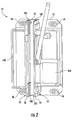
FIG. 2 is a front view of a safety actuation housing assembly according to an embodiment of the present disclosure; -
FIG. 3 is a top view of a safety actuation housing assembly according to an embodiment of the present disclosure; -
FIG. 4 is a front view of a safety actuation housing assembly according to another embodiment of the present disclosure; and -
FIG. 5 is a top view of a safety actuation housing assembly according to another embodiment of the present disclosure. - For the purposes of promoting an understanding of the principles of the present disclosure, reference will now be made to the embodiments illustrated in the drawings, and specific language will be used to describe the same. It will nevertheless be understood that no limitation of the scope of this disclosure is thereby intended.
-
FIG. 1 shows an elevator system, generally indicated at 10. Theelevator system 10 includescables 12, acar frame 14, acar 16,roller guides 18,guide rails 20, agovernor 22,safeties 24,linkages 26,levers 28, andlift rods 30.Governor 22 includes a governor sheave 32,rope loop 34, and a tensioningsheave 36.Cables 12 are connected tocar frame 14 and a counterweight (not shown inFIG. 1 ) inside a hoistway.Car 16, which is attached tocar frame 14, moves up and down the hoistway by force transmitted throughcables 12 tocar frame 14 by an elevator drive (not shown) commonly located in a machine room at the top of the hoistway.Roller guides 18 are attached tocar frame 14 to guide thecar 16 up and down the hoistway alongguide rail 20. Governor sheave 32 is mounted at an upper end of the hoistway.Rope loop 34 is wrapped partially around governorsheave 32 and partially around tensioning sheave 36 (located in this embodiment at a bottom end of the hoistway).Rope loop 34 is also connected toelevator car 16 atlever 28, ensuring that the angular velocity ofgovernor sheave 32 is directly related to the speed ofelevator car 16 - In the
elevator system 10 shown inFIG. 1 , governor 22, an electromechanical brake (not shown) located in the machine room, andsafeties 24 act to stopelevator car 16 ifcar 16 exceeds a set speed as it travels inside the hoistway. Ifcar 16 reaches an over-speed condition, governor 22 is triggered initially to engage a switch, which in turn cuts power to the elevator drive and drops the brake to arrest movement of the drive sheave and thereby arrest movement ofcar 16. If, however,cables 12 break orcar 16 otherwise experiences a free-fall condition unaffected by the brake,governor 22 may then act to triggersafeties 24 to arrest movement ofcar 16. In addition to engaging a switch to drop the brake, governor 22 also releases a clutching device that grips the governor rope 34.Governor rope 34 is connected tosafeties 24 throughmechanical linkages 26, levers 28, andlift rods 30. Ascar 16 continues its descent unaffected by the brake,governor rope 34, which is now prevented from moving by actuatedgovernor 22, pulls on operatinglever 28.Operating lever 28 "sets"safeties 24 by movinglinkages 26 connected tolift rods 30, which liftrods 30 causesafeties 24 to engageguide rails 20 to bringcar 16 to a stop. -
FIG. 2 shows an embodiment of a housing assembly for asafety actuation device 40 configured to be affixed to thecar frame 14. Thehousing assembly 40 includes amounting plate 42. In one embodiment, theassembly 40 includes at least one elevator accessory 44 affixed to themounting plate 42. It will be appreciated that the at least one elevator accessory may include a safety actuation device, and one or more sensors to name a couple of non-limiting examples. - In an embodiment, the
mounting plate 42 includes at least oneaperture 46 disposed therein for mounting theassembly 40 to thecar frame 14. Theapertures 46 on the mountingplate 42 and the fasteners fixed on thecar frame 14 allow a safety actuation device 44A to be floating horizontally when there is position variation between thecar 16 and therail 20, which typically occurs during actuating and resetting thesafeties 24, as well as an elevator normal run. - The
assembly 40 further includes afirst channel wall 48 including a first channel wallinterior surface 50, and asecond channel wall 52 including a second channel wallinterior surface 54. Thefirst channel wall 48 and thesecond channel wall 52 extend substantially perpendicular from the mountingplate 42, and thefirst guide wall 48 is positioned substantially parallel to thesecond guide wall 52 to form achannel 56 therebetween. - The
assembly 40 further includes at least one guide device 58 configured to engage a component disposed within thechannel 56. In an embodiment, the at least one guide device 58 includes at least one guide pad 58 affixed to the first channel wallinterior surface 50 and the second channel wallinterior surface 54. - In some embodiments, each of the at least one guide pads 58 is affixed to the first channel wall
interior surface 50 and positioned adjacent to each of the at least one guide pads 58 affixed to the second channel wallinterior surface 54. For example, in the embodiment shown, theguide pads interior surface 50 towards the ends, and theguide pads interior surface 54 substantially adjacent to theguide pads - In another embodiment, the at least one guide pads 58 are removable for replacement and service purposes. It will be appreciated that the at least one guide pads 58 may be composed of a high weight, wear resistant plastic to name one non-limiting example.
- As shown in
FIG. 3 , therail 20 is disposed with thechannel 56. The at least oneguide pads rail 20 to minimize the impact of position variations between thecar 16 and therail 20. Moreover, the at least oneguide pads channel 56 to obstruct the safety actuator 44A. - In another embodiment, as shown in
FIG. 4 , the mountingplate 42 includes aflange 62 extending from aproximate end 64 of the mountingplate 42. Theflange 62 includes aslot 66 disposed in theflange 62, wherein theslot 66 is substantially aligned with thechannel 56. Theflange 62 is configured to prevent small objects from entering thechannel 56 to obstruct the safety actuator 44A. It will be appreciated that theflange 62 may extend from theproximate end 64, adistal end 68 of the mountingplate 42, or both. - In the embodiment shown in
FIG. 4 , theassembly 40 further includes at least one guide device 58 affixed to the mountingplate 42. In this embodiment, the at least one guide device includes afirst roller 58A and asecond roller 58B affixed to the mountingplate 42. Thefirst roller 58A is located adjacent to thesecond roller 58B to form agap 60 therebetween, wherein thegap 60 is substantially aligned with thechannel 56 and theslot 66. In another embodiment, thefirst roller 58A and asecond roller 58B are removable for replacement and service purposes. It will be appreciated that thefirst roller 58A and thesecond roller 58B may be positioned above and/or below thefirst channel wall 48 and thesecond channel wall 52 - As shown in
FIG. 5 , therail 20 is disposed with thechannel 56, theslot 66, and thegap 60. Thefirst roller 58A and thesecond roller 58B are engaged with therail 20 to minimize the impact of position variations between thecar 16 and therail 20. - It will therefore be appreciated that the present embodiments include a mounting
assembly 40 having at least one guide device 58 disposed withinchannel 56, or alternatively at least one guide device 58 affixed to the mountingplate 42 to formgap 60 substantially aligned with the channel 56to improve the performance of safety actuation and reset due to the minimized position variations between thecar 16 and therail 20. As a result, the power requirements for safety actuation is reduced, and effectively reducing the cost of theelevator system 10. - While the disclosure has been illustrated and described in detail in the drawings and foregoing description, the same is to be considered as illustrative and not restrictive in character, it being understood that only certain embodiments have been shown and described and that all changes and modifications that come within the scope of the disclosure are desired to be protected.
Claims (10)
- A housing assembly (40) for a safety actuation device comprising:a mounting plate (42);a first channel wall (48) and a second channel wall (52) extending substantially perpendicular from the mounting plate (42), the first channel wall (48) including a first channel wall interior surface (50), and the second channel wall (52) including a second channel wall interior surface (54), wherein the first channel wall (48) is positioned substantially parallel to the second channel wall (52) to form a channel (56) therebetween; andat least one guide (58A,58C) device affixed to the first channel wall interior surface (50) and the second channel wall interior surface (54).
- The assembly of claim 1, wherein each of the at least one guide devices (58A) affixed to the first channel wall interior surface (50) is positioned adjacent to each of the at least one guide devices (58C) affixed to the second channel wall interior surface (54).
- The assembly of claim 1 or 2, wherein the at least one guide device (58) is removable.
- The assembly of any of the preceding claims, wherein the at least one guide device (58) comprises a guide pad (58A,58B,58C,58D).
- A housing assembly (40) for a safety actuation device comprising:a mounting plate (42) including a proximal end (64) and a distal end (68);a first channel wall (48) and a second channel wall (52) extending substantially perpendicular from the mounting plate (42), wherein the first channel wall (48) is positioned substantially parallel to the second channel wall (52) to form a channel (56) therebetween; anda flange (62) extending from at least one of the proximal end (64) and the distal end (68), the flange (62) including a slot (66) disposed therein, wherein the slot (66) is substantially aligned with the channel (56).
- The assembly of claim 5, further comprising at least one guide device (58) affixed to the mounting plate (42).
- The assembly of claim 6, wherein the at least one guide device (58) comprises a first roller (58A) and a second roller (58B), wherein the first roller (58A) is located adjacent to the second roller (58B) to form a gap (60) therebetween, wherein the gap (60) is positioned substantially aligned with the channel (56) and the slot (66).
- The assembly of any of the preceding claims, further comprising at least one aperture (46) disposed within the mounting plate (42), the at least one aperture (46) configured for mounting said assembly (40).
- The assembly of any of the preceding claims, further comprising at least one elevator accessory affixed to the mounting plate (42).
- An elevator system (10) comprising:an elevator rail (20);an elevator car frame (14);an elevator car (16) affixed to the elevator car frame (14), the elevator car (16) is configured to travel along the elevator rail (20); anda housing assembly (40) for a safety actuation device affixed to the elevator car (16), the housing assembly (40) being the assembly of any preceding claim.
Applications Claiming Priority (1)
| Application Number | Priority Date | Filing Date | Title |
|---|---|---|---|
| US201562215306P | 2015-09-08 | 2015-09-08 |
Publications (2)
| Publication Number | Publication Date |
|---|---|
| EP3141511A1 true EP3141511A1 (en) | 2017-03-15 |
| EP3141511B1 EP3141511B1 (en) | 2019-01-02 |
Family
ID=56979355
Family Applications (1)
| Application Number | Title | Priority Date | Filing Date |
|---|---|---|---|
| EP16187652.9A Not-in-force EP3141511B1 (en) | 2015-09-08 | 2016-09-07 | Housing assembly for a safety actuation device |
Country Status (5)
| Country | Link |
|---|---|
| US (1) | US20170066627A1 (en) |
| EP (1) | EP3141511B1 (en) |
| KR (1) | KR20170030056A (en) |
| CN (1) | CN106956992A (en) |
| ES (1) | ES2715549T3 (en) |
Cited By (3)
| Publication number | Priority date | Publication date | Assignee | Title |
|---|---|---|---|---|
| EP3447017A3 (en) * | 2017-08-25 | 2019-03-20 | Otis Elevator Company | Synchronized electronic safety actuator |
| EP3377433B1 (en) * | 2015-11-20 | 2021-03-03 | Otis Elevator Company | Housing assembly for a safety actuation device |
| EP3831759A1 (en) | 2019-12-02 | 2021-06-09 | Inventio AG | Device for guiding and braking a vehicle body of a lift system to be displaced along a guide rail |
Families Citing this family (10)
| Publication number | Priority date | Publication date | Assignee | Title |
|---|---|---|---|---|
| JP6807753B2 (en) * | 2014-06-12 | 2021-01-06 | オーチス エレベータ カンパニーOtis Elevator Company | Brake member drive mechanism |
| EP3154891B1 (en) | 2014-06-12 | 2018-12-12 | Otis Elevator Company | Braking system resetting mechanism for a hoisted structure |
| EP3210926B1 (en) * | 2016-02-23 | 2020-01-01 | Otis Elevator Company | Elevator service panel |
| US20180162693A1 (en) * | 2016-12-13 | 2018-06-14 | Otis Elevator Company | Speed detection means for elevator or counterweight |
| EP3564171B1 (en) * | 2018-04-30 | 2021-04-14 | Otis Elevator Company | Elevator safety gear actuation device |
| US11078045B2 (en) * | 2018-05-15 | 2021-08-03 | Otis Elevator Company | Electronic safety actuator for lifting a safety wedge of an elevator |
| EP3587327B1 (en) * | 2018-06-28 | 2020-10-14 | Otis Elevator Company | Electronic safety actuator electromagnetic guidance |
| US11053097B2 (en) * | 2018-07-26 | 2021-07-06 | Otis Elevator Company | Magnet assembly for an electronic safety brake actuator (ESBA) |
| US11603288B2 (en) * | 2020-06-29 | 2023-03-14 | Otis Elevator Company | Magnet assemblies of electromechanical actuators for elevator systems |
| KR20250016181A (en) * | 2022-05-26 | 2025-02-03 | 다이나텍, 다이나믹스 앤드 테크놀러지, 에스. 엘. | Compact electromechanical activation system for safety devices in elevators |
Citations (3)
| Publication number | Priority date | Publication date | Assignee | Title |
|---|---|---|---|---|
| US20020185342A1 (en) * | 2001-06-07 | 2002-12-12 | Edmund Bausch | Braking device that can be released electromagnetically |
| EP1460020A1 (en) * | 2003-03-20 | 2004-09-22 | Thyssenkrupp Elevator Manufacturing France S.A.S. | Elevator safety gear |
| US20120152663A1 (en) * | 2010-12-17 | 2012-06-21 | Benoit Legeret | Activating a safety gear |
-
2016
- 2016-09-07 KR KR1020160114918A patent/KR20170030056A/en not_active Withdrawn
- 2016-09-07 ES ES16187652T patent/ES2715549T3/en active Active
- 2016-09-07 CN CN201610809448.7A patent/CN106956992A/en active Pending
- 2016-09-07 EP EP16187652.9A patent/EP3141511B1/en not_active Not-in-force
- 2016-09-08 US US15/260,109 patent/US20170066627A1/en not_active Abandoned
Patent Citations (3)
| Publication number | Priority date | Publication date | Assignee | Title |
|---|---|---|---|---|
| US20020185342A1 (en) * | 2001-06-07 | 2002-12-12 | Edmund Bausch | Braking device that can be released electromagnetically |
| EP1460020A1 (en) * | 2003-03-20 | 2004-09-22 | Thyssenkrupp Elevator Manufacturing France S.A.S. | Elevator safety gear |
| US20120152663A1 (en) * | 2010-12-17 | 2012-06-21 | Benoit Legeret | Activating a safety gear |
Cited By (7)
| Publication number | Priority date | Publication date | Assignee | Title |
|---|---|---|---|---|
| EP3377433B1 (en) * | 2015-11-20 | 2021-03-03 | Otis Elevator Company | Housing assembly for a safety actuation device |
| EP3447017A3 (en) * | 2017-08-25 | 2019-03-20 | Otis Elevator Company | Synchronized electronic safety actuator |
| US10562739B2 (en) | 2017-08-25 | 2020-02-18 | Otis Elevator Company | Synchronized electronic safety actuator |
| EP3831759A1 (en) | 2019-12-02 | 2021-06-09 | Inventio AG | Device for guiding and braking a vehicle body of a lift system to be displaced along a guide rail |
| WO2021110726A1 (en) | 2019-12-02 | 2021-06-10 | Inventio Ag | Apparatus for guiding and braking a travelling body of a lift system, which body is to be moved along a guide track |
| AU2020396188B2 (en) * | 2019-12-02 | 2024-07-11 | Inventio Ag | Apparatus for guiding and braking a travelling body of a lift system, which body is to be moved along a guide track |
| US12077415B2 (en) | 2019-12-02 | 2024-09-03 | Inventio Ag | Apparatus for guiding and braking a travelling body of an elevator system, which body is to be moved along a guide track |
Also Published As
| Publication number | Publication date |
|---|---|
| EP3141511B1 (en) | 2019-01-02 |
| ES2715549T3 (en) | 2019-06-04 |
| CN106956992A (en) | 2017-07-18 |
| KR20170030056A (en) | 2017-03-16 |
| US20170066627A1 (en) | 2017-03-09 |
Similar Documents
| Publication | Publication Date | Title |
|---|---|---|
| EP3141511B1 (en) | Housing assembly for a safety actuation device | |
| EP3112306B1 (en) | Electromagnetic safety trigger | |
| EP3377433B1 (en) | Housing assembly for a safety actuation device | |
| EP3377434B1 (en) | Electronic safety actuator | |
| US11066274B2 (en) | Electromagnetic safety trigger | |
| EP3231756B1 (en) | Electronic safety actuation device with a power assembly | |
| KR101456403B1 (en) | Elevator device | |
| US8550217B2 (en) | Elevator | |
| US9359173B2 (en) | Elevator governor having two tripping mechanisms on separate sheaves | |
| JP6465995B2 (en) | Elevator equipment | |
| US11078045B2 (en) | Electronic safety actuator for lifting a safety wedge of an elevator | |
| EP3210926B1 (en) | Elevator service panel | |
| JP2000211841A (en) | Device for stopping motion of elevator device | |
| EP3587328A2 (en) | Electromagnetic safety trigger | |
| JP6188962B2 (en) | Elevator equipment | |
| JP6362520B2 (en) | Elevator safety device | |
| CN113498399A (en) | Triggering system for a safety gear, elevator installation and method for operating an elevator installation | |
| EP3929130B1 (en) | Safety link with a pulley | |
| US11970367B2 (en) | Safety brake actuator |
Legal Events
| Date | Code | Title | Description |
|---|---|---|---|
| PUAI | Public reference made under article 153(3) epc to a published international application that has entered the european phase |
Free format text: ORIGINAL CODE: 0009012 |
|
| STAA | Information on the status of an ep patent application or granted ep patent |
Free format text: STATUS: THE APPLICATION HAS BEEN PUBLISHED |
|
| AK | Designated contracting states |
Kind code of ref document: A1 Designated state(s): AL AT BE BG CH CY CZ DE DK EE ES FI FR GB GR HR HU IE IS IT LI LT LU LV MC MK MT NL NO PL PT RO RS SE SI SK SM TR |
|
| AX | Request for extension of the european patent |
Extension state: BA ME |
|
| RAP1 | Party data changed (applicant data changed or rights of an application transferred) |
Owner name: OTIS ELEVATOR COMPANY |
|
| STAA | Information on the status of an ep patent application or granted ep patent |
Free format text: STATUS: REQUEST FOR EXAMINATION WAS MADE |
|
| 17P | Request for examination filed |
Effective date: 20170914 |
|
| RBV | Designated contracting states (corrected) |
Designated state(s): AL AT BE BG CH CY CZ DE DK EE ES FI FR GB GR HR HU IE IS IT LI LT LU LV MC MK MT NL NO PL PT RO RS SE SI SK SM TR |
|
| GRAP | Despatch of communication of intention to grant a patent |
Free format text: ORIGINAL CODE: EPIDOSNIGR1 |
|
| STAA | Information on the status of an ep patent application or granted ep patent |
Free format text: STATUS: GRANT OF PATENT IS INTENDED |
|
| INTG | Intention to grant announced |
Effective date: 20180720 |
|
| GRAS | Grant fee paid |
Free format text: ORIGINAL CODE: EPIDOSNIGR3 |
|
| GRAA | (expected) grant |
Free format text: ORIGINAL CODE: 0009210 |
|
| STAA | Information on the status of an ep patent application or granted ep patent |
Free format text: STATUS: THE PATENT HAS BEEN GRANTED |
|
| AK | Designated contracting states |
Kind code of ref document: B1 Designated state(s): AL AT BE BG CH CY CZ DE DK EE ES FI FR GB GR HR HU IE IS IT LI LT LU LV MC MK MT NL NO PL PT RO RS SE SI SK SM TR |
|
| REG | Reference to a national code |
Ref country code: GB Ref legal event code: FG4D |
|
| REG | Reference to a national code |
Ref country code: CH Ref legal event code: EP Ref country code: AT Ref legal event code: REF Ref document number: 1084117 Country of ref document: AT Kind code of ref document: T Effective date: 20190115 |
|
| REG | Reference to a national code |
Ref country code: IE Ref legal event code: FG4D |
|
| REG | Reference to a national code |
Ref country code: DE Ref legal event code: R096 Ref document number: 602016008893 Country of ref document: DE |
|
| REG | Reference to a national code |
Ref country code: NL Ref legal event code: MP Effective date: 20190102 |
|
| REG | Reference to a national code |
Ref country code: LT Ref legal event code: MG4D |
|
| REG | Reference to a national code |
Ref country code: ES Ref legal event code: FG2A Ref document number: 2715549 Country of ref document: ES Kind code of ref document: T3 Effective date: 20190604 |
|
| REG | Reference to a national code |
Ref country code: AT Ref legal event code: MK05 Ref document number: 1084117 Country of ref document: AT Kind code of ref document: T Effective date: 20190102 |
|
| PG25 | Lapsed in a contracting state [announced via postgrant information from national office to epo] |
Ref country code: NL Free format text: LAPSE BECAUSE OF FAILURE TO SUBMIT A TRANSLATION OF THE DESCRIPTION OR TO PAY THE FEE WITHIN THE PRESCRIBED TIME-LIMIT Effective date: 20190102 |
|
| PG25 | Lapsed in a contracting state [announced via postgrant information from national office to epo] |
Ref country code: LT Free format text: LAPSE BECAUSE OF FAILURE TO SUBMIT A TRANSLATION OF THE DESCRIPTION OR TO PAY THE FEE WITHIN THE PRESCRIBED TIME-LIMIT Effective date: 20190102 Ref country code: PL Free format text: LAPSE BECAUSE OF FAILURE TO SUBMIT A TRANSLATION OF THE DESCRIPTION OR TO PAY THE FEE WITHIN THE PRESCRIBED TIME-LIMIT Effective date: 20190102 Ref country code: FI Free format text: LAPSE BECAUSE OF FAILURE TO SUBMIT A TRANSLATION OF THE DESCRIPTION OR TO PAY THE FEE WITHIN THE PRESCRIBED TIME-LIMIT Effective date: 20190102 Ref country code: NO Free format text: LAPSE BECAUSE OF FAILURE TO SUBMIT A TRANSLATION OF THE DESCRIPTION OR TO PAY THE FEE WITHIN THE PRESCRIBED TIME-LIMIT Effective date: 20190402 Ref country code: PT Free format text: LAPSE BECAUSE OF FAILURE TO SUBMIT A TRANSLATION OF THE DESCRIPTION OR TO PAY THE FEE WITHIN THE PRESCRIBED TIME-LIMIT Effective date: 20190502 Ref country code: SE Free format text: LAPSE BECAUSE OF FAILURE TO SUBMIT A TRANSLATION OF THE DESCRIPTION OR TO PAY THE FEE WITHIN THE PRESCRIBED TIME-LIMIT Effective date: 20190102 |
|
| PG25 | Lapsed in a contracting state [announced via postgrant information from national office to epo] |
Ref country code: IS Free format text: LAPSE BECAUSE OF FAILURE TO SUBMIT A TRANSLATION OF THE DESCRIPTION OR TO PAY THE FEE WITHIN THE PRESCRIBED TIME-LIMIT Effective date: 20190502 Ref country code: RS Free format text: LAPSE BECAUSE OF FAILURE TO SUBMIT A TRANSLATION OF THE DESCRIPTION OR TO PAY THE FEE WITHIN THE PRESCRIBED TIME-LIMIT Effective date: 20190102 Ref country code: LV Free format text: LAPSE BECAUSE OF FAILURE TO SUBMIT A TRANSLATION OF THE DESCRIPTION OR TO PAY THE FEE WITHIN THE PRESCRIBED TIME-LIMIT Effective date: 20190102 Ref country code: GR Free format text: LAPSE BECAUSE OF FAILURE TO SUBMIT A TRANSLATION OF THE DESCRIPTION OR TO PAY THE FEE WITHIN THE PRESCRIBED TIME-LIMIT Effective date: 20190403 Ref country code: BG Free format text: LAPSE BECAUSE OF FAILURE TO SUBMIT A TRANSLATION OF THE DESCRIPTION OR TO PAY THE FEE WITHIN THE PRESCRIBED TIME-LIMIT Effective date: 20190402 Ref country code: HR Free format text: LAPSE BECAUSE OF FAILURE TO SUBMIT A TRANSLATION OF THE DESCRIPTION OR TO PAY THE FEE WITHIN THE PRESCRIBED TIME-LIMIT Effective date: 20190102 |
|
| REG | Reference to a national code |
Ref country code: DE Ref legal event code: R097 Ref document number: 602016008893 Country of ref document: DE |
|
| PG25 | Lapsed in a contracting state [announced via postgrant information from national office to epo] |
Ref country code: AL Free format text: LAPSE BECAUSE OF FAILURE TO SUBMIT A TRANSLATION OF THE DESCRIPTION OR TO PAY THE FEE WITHIN THE PRESCRIBED TIME-LIMIT Effective date: 20190102 Ref country code: SK Free format text: LAPSE BECAUSE OF FAILURE TO SUBMIT A TRANSLATION OF THE DESCRIPTION OR TO PAY THE FEE WITHIN THE PRESCRIBED TIME-LIMIT Effective date: 20190102 Ref country code: CZ Free format text: LAPSE BECAUSE OF FAILURE TO SUBMIT A TRANSLATION OF THE DESCRIPTION OR TO PAY THE FEE WITHIN THE PRESCRIBED TIME-LIMIT Effective date: 20190102 Ref country code: RO Free format text: LAPSE BECAUSE OF FAILURE TO SUBMIT A TRANSLATION OF THE DESCRIPTION OR TO PAY THE FEE WITHIN THE PRESCRIBED TIME-LIMIT Effective date: 20190102 Ref country code: EE Free format text: LAPSE BECAUSE OF FAILURE TO SUBMIT A TRANSLATION OF THE DESCRIPTION OR TO PAY THE FEE WITHIN THE PRESCRIBED TIME-LIMIT Effective date: 20190102 Ref country code: AT Free format text: LAPSE BECAUSE OF FAILURE TO SUBMIT A TRANSLATION OF THE DESCRIPTION OR TO PAY THE FEE WITHIN THE PRESCRIBED TIME-LIMIT Effective date: 20190102 Ref country code: DK Free format text: LAPSE BECAUSE OF FAILURE TO SUBMIT A TRANSLATION OF THE DESCRIPTION OR TO PAY THE FEE WITHIN THE PRESCRIBED TIME-LIMIT Effective date: 20190102 Ref country code: IT Free format text: LAPSE BECAUSE OF FAILURE TO SUBMIT A TRANSLATION OF THE DESCRIPTION OR TO PAY THE FEE WITHIN THE PRESCRIBED TIME-LIMIT Effective date: 20190102 |
|
| PLBE | No opposition filed within time limit |
Free format text: ORIGINAL CODE: 0009261 |
|
| STAA | Information on the status of an ep patent application or granted ep patent |
Free format text: STATUS: NO OPPOSITION FILED WITHIN TIME LIMIT |
|
| PG25 | Lapsed in a contracting state [announced via postgrant information from national office to epo] |
Ref country code: SM Free format text: LAPSE BECAUSE OF FAILURE TO SUBMIT A TRANSLATION OF THE DESCRIPTION OR TO PAY THE FEE WITHIN THE PRESCRIBED TIME-LIMIT Effective date: 20190102 |
|
| 26N | No opposition filed |
Effective date: 20191003 |
|
| PG25 | Lapsed in a contracting state [announced via postgrant information from national office to epo] |
Ref country code: SI Free format text: LAPSE BECAUSE OF FAILURE TO SUBMIT A TRANSLATION OF THE DESCRIPTION OR TO PAY THE FEE WITHIN THE PRESCRIBED TIME-LIMIT Effective date: 20190102 |
|
| PGFP | Annual fee paid to national office [announced via postgrant information from national office to epo] |
Ref country code: ES Payment date: 20191001 Year of fee payment: 4 |
|
| PG25 | Lapsed in a contracting state [announced via postgrant information from national office to epo] |
Ref country code: TR Free format text: LAPSE BECAUSE OF FAILURE TO SUBMIT A TRANSLATION OF THE DESCRIPTION OR TO PAY THE FEE WITHIN THE PRESCRIBED TIME-LIMIT Effective date: 20190102 |
|
| PG25 | Lapsed in a contracting state [announced via postgrant information from national office to epo] |
Ref country code: MC Free format text: LAPSE BECAUSE OF FAILURE TO SUBMIT A TRANSLATION OF THE DESCRIPTION OR TO PAY THE FEE WITHIN THE PRESCRIBED TIME-LIMIT Effective date: 20190102 |
|
| REG | Reference to a national code |
Ref country code: CH Ref legal event code: PL |
|
| PG25 | Lapsed in a contracting state [announced via postgrant information from national office to epo] |
Ref country code: CH Free format text: LAPSE BECAUSE OF NON-PAYMENT OF DUE FEES Effective date: 20190930 Ref country code: LI Free format text: LAPSE BECAUSE OF NON-PAYMENT OF DUE FEES Effective date: 20190930 Ref country code: LU Free format text: LAPSE BECAUSE OF NON-PAYMENT OF DUE FEES Effective date: 20190907 Ref country code: IE Free format text: LAPSE BECAUSE OF NON-PAYMENT OF DUE FEES Effective date: 20190907 |
|
| REG | Reference to a national code |
Ref country code: BE Ref legal event code: MM Effective date: 20190930 |
|
| PG25 | Lapsed in a contracting state [announced via postgrant information from national office to epo] |
Ref country code: BE Free format text: LAPSE BECAUSE OF NON-PAYMENT OF DUE FEES Effective date: 20190930 |
|
| PGFP | Annual fee paid to national office [announced via postgrant information from national office to epo] |
Ref country code: FR Payment date: 20200819 Year of fee payment: 5 Ref country code: DE Payment date: 20200819 Year of fee payment: 5 |
|
| GBPC | Gb: european patent ceased through non-payment of renewal fee |
Effective date: 20200907 |
|
| PG25 | Lapsed in a contracting state [announced via postgrant information from national office to epo] |
Ref country code: CY Free format text: LAPSE BECAUSE OF FAILURE TO SUBMIT A TRANSLATION OF THE DESCRIPTION OR TO PAY THE FEE WITHIN THE PRESCRIBED TIME-LIMIT Effective date: 20190102 |
|
| PG25 | Lapsed in a contracting state [announced via postgrant information from national office to epo] |
Ref country code: MT Free format text: LAPSE BECAUSE OF FAILURE TO SUBMIT A TRANSLATION OF THE DESCRIPTION OR TO PAY THE FEE WITHIN THE PRESCRIBED TIME-LIMIT Effective date: 20190102 Ref country code: HU Free format text: LAPSE BECAUSE OF FAILURE TO SUBMIT A TRANSLATION OF THE DESCRIPTION OR TO PAY THE FEE WITHIN THE PRESCRIBED TIME-LIMIT; INVALID AB INITIO Effective date: 20160907 |
|
| PG25 | Lapsed in a contracting state [announced via postgrant information from national office to epo] |
Ref country code: GB Free format text: LAPSE BECAUSE OF NON-PAYMENT OF DUE FEES Effective date: 20200907 |
|
| REG | Reference to a national code |
Ref country code: ES Ref legal event code: FD2A Effective date: 20220114 |
|
| REG | Reference to a national code |
Ref country code: DE Ref legal event code: R119 Ref document number: 602016008893 Country of ref document: DE |
|
| PG25 | Lapsed in a contracting state [announced via postgrant information from national office to epo] |
Ref country code: ES Free format text: LAPSE BECAUSE OF NON-PAYMENT OF DUE FEES Effective date: 20200908 |
|
| PG25 | Lapsed in a contracting state [announced via postgrant information from national office to epo] |
Ref country code: MK Free format text: LAPSE BECAUSE OF FAILURE TO SUBMIT A TRANSLATION OF THE DESCRIPTION OR TO PAY THE FEE WITHIN THE PRESCRIBED TIME-LIMIT Effective date: 20190102 |
|
| PG25 | Lapsed in a contracting state [announced via postgrant information from national office to epo] |
Ref country code: FR Free format text: LAPSE BECAUSE OF NON-PAYMENT OF DUE FEES Effective date: 20210930 Ref country code: DE Free format text: LAPSE BECAUSE OF NON-PAYMENT OF DUE FEES Effective date: 20220401 |