EP3141439A1 - Board-like body for electrically heated window - Google Patents
Board-like body for electrically heated window Download PDFInfo
- Publication number
- EP3141439A1 EP3141439A1 EP15786231.9A EP15786231A EP3141439A1 EP 3141439 A1 EP3141439 A1 EP 3141439A1 EP 15786231 A EP15786231 A EP 15786231A EP 3141439 A1 EP3141439 A1 EP 3141439A1
- Authority
- EP
- European Patent Office
- Prior art keywords
- region
- bus bar
- conductive film
- transparent conductive
- plate
- Prior art date
- Legal status (The legal status is an assumption and is not a legal conclusion. Google has not performed a legal analysis and makes no representation as to the accuracy of the status listed.)
- Granted
Links
Images






Classifications
-
- B—PERFORMING OPERATIONS; TRANSPORTING
- B60—VEHICLES IN GENERAL
- B60S—SERVICING, CLEANING, REPAIRING, SUPPORTING, LIFTING, OR MANOEUVRING OF VEHICLES, NOT OTHERWISE PROVIDED FOR
- B60S1/00—Cleaning of vehicles
- B60S1/02—Cleaning windscreens, windows or optical devices
-
- B—PERFORMING OPERATIONS; TRANSPORTING
- B60—VEHICLES IN GENERAL
- B60S—SERVICING, CLEANING, REPAIRING, SUPPORTING, LIFTING, OR MANOEUVRING OF VEHICLES, NOT OTHERWISE PROVIDED FOR
- B60S1/00—Cleaning of vehicles
- B60S1/02—Cleaning windscreens, windows or optical devices
- B60S1/56—Cleaning windscreens, windows or optical devices specially adapted for cleaning other parts or devices than front windows or windscreens
- B60S1/58—Cleaning windscreens, windows or optical devices specially adapted for cleaning other parts or devices than front windows or windscreens for rear windows
-
- B—PERFORMING OPERATIONS; TRANSPORTING
- B60—VEHICLES IN GENERAL
- B60S—SERVICING, CLEANING, REPAIRING, SUPPORTING, LIFTING, OR MANOEUVRING OF VEHICLES, NOT OTHERWISE PROVIDED FOR
- B60S1/00—Cleaning of vehicles
- B60S1/02—Cleaning windscreens, windows or optical devices
- B60S1/56—Cleaning windscreens, windows or optical devices specially adapted for cleaning other parts or devices than front windows or windscreens
- B60S1/58—Cleaning windscreens, windows or optical devices specially adapted for cleaning other parts or devices than front windows or windscreens for rear windows
- B60S1/586—Cleaning windscreens, windows or optical devices specially adapted for cleaning other parts or devices than front windows or windscreens for rear windows including defroster or demisting means
-
- H—ELECTRICITY
- H05—ELECTRIC TECHNIQUES NOT OTHERWISE PROVIDED FOR
- H05B—ELECTRIC HEATING; ELECTRIC LIGHT SOURCES NOT OTHERWISE PROVIDED FOR; CIRCUIT ARRANGEMENTS FOR ELECTRIC LIGHT SOURCES, IN GENERAL
- H05B3/00—Ohmic-resistance heating
- H05B3/84—Heating arrangements specially adapted for transparent or reflecting areas, e.g. for demisting or de-icing windows, mirrors or vehicle windshields
-
- H—ELECTRICITY
- H05—ELECTRIC TECHNIQUES NOT OTHERWISE PROVIDED FOR
- H05B—ELECTRIC HEATING; ELECTRIC LIGHT SOURCES NOT OTHERWISE PROVIDED FOR; CIRCUIT ARRANGEMENTS FOR ELECTRIC LIGHT SOURCES, IN GENERAL
- H05B2203/00—Aspects relating to Ohmic resistive heating covered by group H05B3/00
- H05B2203/011—Heaters using laterally extending conductive material as connecting means
-
- H—ELECTRICITY
- H05—ELECTRIC TECHNIQUES NOT OTHERWISE PROVIDED FOR
- H05B—ELECTRIC HEATING; ELECTRIC LIGHT SOURCES NOT OTHERWISE PROVIDED FOR; CIRCUIT ARRANGEMENTS FOR ELECTRIC LIGHT SOURCES, IN GENERAL
- H05B2203/00—Aspects relating to Ohmic resistive heating covered by group H05B3/00
- H05B2203/013—Heaters using resistive films or coatings
-
- H—ELECTRICITY
- H05—ELECTRIC TECHNIQUES NOT OTHERWISE PROVIDED FOR
- H05B—ELECTRIC HEATING; ELECTRIC LIGHT SOURCES NOT OTHERWISE PROVIDED FOR; CIRCUIT ARRANGEMENTS FOR ELECTRIC LIGHT SOURCES, IN GENERAL
- H05B2203/00—Aspects relating to Ohmic resistive heating covered by group H05B3/00
- H05B2203/031—Heaters specially adapted for heating the windscreen wiper area
-
- H—ELECTRICITY
- H05—ELECTRIC TECHNIQUES NOT OTHERWISE PROVIDED FOR
- H05B—ELECTRIC HEATING; ELECTRIC LIGHT SOURCES NOT OTHERWISE PROVIDED FOR; CIRCUIT ARRANGEMENTS FOR ELECTRIC LIGHT SOURCES, IN GENERAL
- H05B3/00—Ohmic-resistance heating
- H05B3/84—Heating arrangements specially adapted for transparent or reflecting areas, e.g. for demisting or de-icing windows, mirrors or vehicle windshields
- H05B3/86—Heating arrangements specially adapted for transparent or reflecting areas, e.g. for demisting or de-icing windows, mirrors or vehicle windshields the heating conductors being embedded in the transparent or reflecting material
Definitions
- the present invention generally relates to a plate for an electro-thermal window including a heatable transparent conductive film and multiple bus bars for feeding electric power to the transparent conductive film.
- Patent Document 1 a plate for an electro-thermal window formed with a transparent conductive film is known (see, for example, Patent Document 1).
- a bus bar is formed on both ends of the transparent conductive film formed in the plate for an electro-thermal window.
- One bus bar is connected to a direct current power source whereas another bus bar is grounded.
- the transparent conductive film When the transparent conductive film is energized, the transparent conductive film generates heat, so that fog (water droplets) or the like created on the plate for the window can be removed.
- fog water droplets
- Patent Document 1 discloses multiple openings being orderly arranged through which electromagnetic waves of a predetermined frequency can be transmitted.
- Patent Document 1 U.S. Patent Publication No. 2006/0010794
- the transparent conductive film is also formed with a substantially trapezoid shape.
- a bus bar is formed on the left and right sides of the substantially trapezoidal-shaped transparent conductive film, the distance between the bus bars becomes different in the vertical direction. Therefore, electric current tends to concentrate at an area where the distance between the bus bars is short and may cause a local area to be heated to a high temperature.
- an aspect of the present invention is to provide a plate for an electro-thermal window that prevents local areas from being heated to a high temperature.
- an embodiment of the present invention provides a plate for an electro-thermal window that includes a transparent conductive film that can be heated, and multiple bus bars that feed power to the transparent conductive film.
- the multiple bus bars include a left bus bar connected to a left side edge part of the transparent conductive film and a right bus bar connected to a right side edge part of the transparent conductive film.
- the transparent conductive film is divided into multiple regions by a slit that is continuously or discontinuously formed from the left bus bar to the right bus bar.
- the multiple regions include a first region and a second region. A distance between the left bus bar and the right bus bar of the first region is shorter than a distance between the left bus bar and the right bus bar of the second region.
- a width of the first region in a direction orthogonal to the slit is shorter than a width of the second region in the direction orthogonal to the slit.
- a plate for an electro-thermal window that prevents local areas from being heated to a high temperature.
- each drawing is a diagram viewed from a side facing a surface of the plate for the electro-thermal window.
- Each drawing is a diagram viewing the inside of a vehicle in a state where the plate for the electro-thermal window is attached to the vehicle. However, each drawing may be assumed to be a diagram viewing the outside of the vehicle.
- a vertical direction corresponds to a vertical direction of a vehicle in which a bottom side of each drawing corresponds to the side of a road.
- a lateral direction corresponds to a width direction of the vehicle.
- the electro-thermal window is not limited to a front glass but may also be a rear glass attached to the rear of a vehicle or a side glass attached to the side of a vehicle.
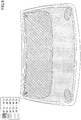
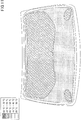
- Fig. 1 is a diagram illustrating a plate for an electro-thermal window according to an embodiment of the present invention.
- a plate for an electro-thermal window 10 is attached to an opening part of a window of a vehicle.
- the plate for an electro-thermal window 10 may be, for example, attached to a window of the front of an automobile. That is, the plate for an electro-thermal window 10 may be provided at the front of a driver of an automobile.
- the plate for an electro-thermal window 10 includes a substantially trapezoidal-shaped plate for a window 11, a substantially trapezoidal-shaped transparent conductive film 12, a left bus bar 13, and a right bus bar 14.
- substantially trapezoidal-shaped is a shape in which an upper side is shorter than a lower side, and preferably a shape in which the lengths between the upper side and the lower side are no less than 10% different from each other.
- the plate for a window 11 includes a transparent plate.
- the transparent plate may be formed of an insulating material such as glass or resin.
- the glass may be, for example, soda-lime glass.
- the resin may be, for example, polycarbonate (PC).
- the plate for a window 11 may include multiple transparent plates.
- the multiple transparent plates may be layered having an intermediate film (e.g., resin film) disposed therebetween.
- the transparent conductive film 12, the left bus bar 13, and the right bus bar 14 may be provided between multiple insulating transparent plates.
- a conductive sheet is connected to each of the left bus bar 13 and the right bus bar 14. Each conductive sheet projects outward from the plate for a window 11 to form an electrode.
- the plate for a window 11 may have a curved shape protruding to the outside of the vehicle.
- the transparent plate of the plate for a window 11 may bent and molded by thermal processing. Multiple bent transparent plates may be press-bonded and interposed by the intermediate film.
- the transparent conductive film 12 may be, for example, a metal film such as an Ag film, a metal oxide film such as a tin-doped indium oxide (ITO) film, or a resin film including fine conductive particles.
- the transparent conductive film 12 may be formed of layers of various kinds of films.
- the transparent conductive film 12 may be formed on an insulating transparent plate. After being deposited on the transparent plate, the transparent conductive film 12 may be bent and molded together with the transparent plate. Alternatively, the transparent conductive film 12 may be deposited on a resin sheet. The transparent conductive film 12, interposed by the resin sheet, may be laminated on a transparent plate that is bent and molded beforehand.
- the method for depositing the transparent conductive film 12 may be, for example, a dry-coating method.
- the dry-coating method may be a physical vapor deposition (PVD) method or a chemical vapor deposition (CVD) method.
- the PVD method is preferably a vacuum deposition method, a sputtering method, or an ion plating method, and more preferably, a sputtering method capable of depositing on a large area.
- this embodiment uses a dry-coating method as the method for depositing the transparent conductive film 12, a wet-coating method may be used.
- the transparent conductive film 12 may have a substantially trapezoidal shape and may be formed slightly smaller than an outer shape of the substantially trapezoidal-shaped plate for a window 11.
- the upper side of the transparent conductive film 12 is substantially parallel to the lower side of the transparent conductive film 12 and shorter than the lower side of the transparent conductive film 12.
- the distance between the left bus bar 13 and the right bus bar 14 (hereinafter referred to as "bus bar distance") becomes shorter toward the upper direction from the lower side of the transparent conductive film 12.
- the left bus bar 13 and the right bus bar 14 are formed along the side edges of the substantially trapezoidal-shaped transparent conductive film 12 and arranged to form an inverted V shape. The distance between the left bus bar 13 and the right bus bar 14 gradually becomes longer from the upper side to the lower side.
- the left bus bar 13 is connected to a left-side edge part of the transparent conductive film 12.
- the right bus bar 14 is connected to a right-side edge part of the transparent conductive film 12. Further, each of the left bus bar 13 and the right bus bar 14 is formed from a continuous conductor.
- the left bus bar 13 is electrically connected to an electric power source whereas the right bus bar 14 is grounded.
- the left bus bar 13 may be grounded whereas the right bus bar 14 is electrically connected to an electric power source.
- the left bus bar 13 and the right bus bar 14 supply electric power to the transparent conductive film 12 to allow the transparent conductive film 12 to generate heat. Thereby, fog or the like created on the plate for a window 11 can be removed. Thus, visibility can be attained for the passenger of the vehicle.
- the transparent conductive film 12 of this embodiment is divided into multiple regions by the slit 21 continuously formed from the left bus bar 13 to the right bus bar 14.
- the multiple regions include a first region 31 and a second region 32.
- the slit 21 may be formed substantially parallel to the upper and lower sides of the transparent conductive film 12.
- the slit 21 may be formed by using a laser or the like.
- the slit 21 penetrates the transparent conductive film 12 in the thickness direction.
- the slit 21 may be formed in an area that would not obstruct the view of the passenger (e.g., driver) of the vehicle.
- the slit 21 may be formed in an area no greater than 500 mm (preferably, no greater than 400 mm, and more preferably, no greater than 300 mm) from the upper side of the transparent conductive film 12 in a downward direction from the upper side of the transparent conductive film 12.
- Substantially the same amount of voltage is applied to the first region 31 and the second region 32 by simultaneously supplying electric power from the single left bus bar 13 and the single right bus bar 14.
- the difference between the maximum value and the minimum value of the bus bar distances in the first region 31 is less than the difference between the maximum value and the minimum value of the bus bar distance of the entire transparent conductive film 12.
- concentration of electric current can be reduced. Accordingly, the heating of local areas in the transparent conductive film 12 can be prevented.
- the electric resistance of the first region 31 is not only defined by the bus bar distance of the first region 31 but also by, for example, the width of the first region 31 in a direction (vertical direction in Fig. 1 ) orthogonal to the slit 21 (hereinafter referred to as "vertical direction width").
- the electric resistance becomes larger the greater the bus bar distance and becomes smaller the greater the vertical direction width.
- the bus bar distance of the first region 31 is shorter than the bus bar distance of the second region 32.
- the vertical direction width of the first region 31 is shorter than the vertical direction width of the second region 32. Therefore, compared to a case where a vertical direction width W1 of the first region 31 is equal to or greater than a vertical direction width W2 of the second region 32, the difference of the electric resistance between the first region 31 and the second region 32 and the difference of the electric current flowing in the first region 31 and the second region 32 are small. Accordingly, the heating of local areas in the transparent conductive film 12 can be further prevented.
- the bus bar distance may be an average value.
- the transparent conductive film 12, by way of the slit 21, forms a frequency selective surface through which a vertically polarized electromagnetic wave of a predetermined frequency is to be transmitted. Thereby, communication inside and outside the vehicle can be achieved.
- the slit 21 may be formed at an upper part of the transparent conductive film 12, so that a wide area inside the vehicle can be used for communicating with the outside of the vehicle.
- the length of the slit 21 is preferably equal to or greater than 85 mm.
- the length of the slit 21 is preferably greater than or equal to 40 mm. Normally, the distance between the left bus bar 13 and the right bus bar 14 is sufficiently longer than 85 mm.
- the wavelength shortening rate k is approximately 0.51.
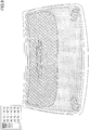
- Fig. 2 is a diagram illustrating a plate for an electro-thermal window according to a first modified example.
- multiple slits 21A, 22A are formed in the transparent conductive film 12.
- Each of the slits 21A, 22A may be formed substantially parallel to the upper and lower sides of the transparent conductive film 12.
- the transparent conductive film 12 is divided into a first region 31A, a second region 32A, and a third region 33A.
- the difference between the maximum value and the minimum value of the bus bar distances in the first region 31A is less than the difference between the maximum value and the minimum value of the bus bar distance of the entire transparent conductive film 12.
- concentration of electric current can be reduced. Accordingly, the heating of local areas in the transparent conductive film 12 can be prevented.
- the electric resistance of the first region 31A is not only defined by the bus bar distance of the first region 31A but also by, for example, the vertical direction width of the first region 31A.
- the electric resistance becomes larger the greater the bus bar distance and becomes smaller the greater the vertical direction width. The same applies to the second region 32A and the third region 33A.
- the first region 31A has a bus bar distance that is shorter than the bus bar distance of the second region 32A
- the second region 32A has a bus bar distance that is shorter than the bus bar distance of the third region 33A
- the first region 31A has a vertical direction width that is shorter than the vertical direction width of the second region 32A
- the second region 32A has a vertical direction width that is shorter than the vertical direction width of the third region 33A. Therefore, compared to a case where the vertical direction widths of each of the regions are equal, the difference among the electric resistance of the first, second, and third regions 31A, 32A, 33A is small. The difference among the electric current flowing in the first, second, and third regions 31A, 32A, 33A is also small. Accordingly, the heating of local areas in the transparent conductive film 12 can be further prevented.
- the transparent conductive film 12 is divided into three or more regions, and the vertical direction width becomes shorter as the bus bar distance of the region becomes shorter. Accordingly, the heating of local areas in the transparent conductive film 12 can be further prevented.
- the transparent conductive film 12 is divided into three or more regions, and as the vertical width among the three regions becomes shorter, the bus bar distance becomes shorter. Accordingly, the heating of local areas in the transparent conductive film 12 can be further prevented.
- vertically polarized electromagnetic waves of a frequency band can be easily transmitted because multiple slits 21A, 22A are formed.
- the interval W between adjacent slits 21A and 22A is preferably less than or equal to ⁇ g /4.
- the interval W between adjacent slits 21A and 22A is preferably less than or equal to 43 mm.
- the interval W between adjacent slits 21A and 22A is preferably less than or equal to 20 mm.
- the transmittance of a vertically polarized wave is sufficiently high if the interval W is less than or equal to ⁇ g /4.
- At least one pair of adjacent slits may have an interval W that is less than or equal to ⁇ g /4.
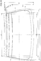
- Fig. 3 is a diagram illustrating a plate for an electro-thermal window according to a second modified example.
- a slit 21B is formed in the transparent conductive film 12.
- the slit 21B may be formed substantially parallel to the upper and lower sides of the transparent conductive film 12.
- the slit 21B is discontinuously formed from the left bus bar 13 to the right bus bar 14.
- the slit 21B in Fig. 3 is formed with a single notch, the slit 21B may be formed with multiple notches.
- a gap G of the notch of the slit 21B may be, for example, less than or equal to 32 mm. If the gap G is less than or equal to 32 mm, electric current between the first and second regions 31B, 32B divided by the slit 21B can practically be separated.
- the gap G is preferably less than or equal to 16 mm.
- the transparent conductive film 12 is divided into the first region 31b and the second region 32B.
- the difference between the maximum value and the minimum value of the bus bar distances in the first region 31B is less than the difference between the maximum value and the minimum value of the bus bar distance of the entire transparent conductive film 12.
- concentration of electric current can be reduced. Accordingly, the heating of local areas in the transparent conductive film 12 can be prevented.
- the electric resistance of the first region 31B is not only defined by the bus bar distance of the first region 31B but also by, for example, the vertical direction width of the first region 31B.
- the electric resistance becomes larger the longer the bus bar distance and becomes smaller the longer the vertical direction width. The same applies to the second region 32B.
- the bus bar distance of the first region 31B is shorter than the bus bar distance of the second region 32B.
- the vertical direction width of the first region 31B is shorter than the vertical direction width of the second region 32B. Therefore, compared to a case where, for example, the vertical direction width of each region is equal, the difference of the electric resistance between the first region 31B and the second region 32B and the difference of the electric current flowing in the first region 31B and the second region 32B when voltage is applied are small. Accordingly, the heating of local areas in the transparent conductive film 12 can be further prevented.
- the slits 21A, 22A illustrated in Fig. 2 may be discontinuously formed from the left bus bar 13 to the right bus bar 14.
- samples 1 to 5 The temperature distribution of samples 1 to 5 was analyzed by thermal stimulation in a case where voltage is applied to a transparent conductive film of a laminated glass including the transparent conductive film.
- the samples 1 to 4 are practical examples whereas the sample 5 is a comparative example.
- the laminated glass included a glass plate, a transparent conductive film, and a glass plate in this order but did not include an intermediate film.
- the dimensions and physical properties of each of the elements were as follows.
- a finite element analysis model of the laminated glass was fabricated by using software "Hypermesh” manufactured by Altair Engineering Ltd.
- the temperature distribution when applying voltage between the bus bars of this model was obtained by using a general-purpose finite element analysis software program "Abaqus/Standard” manufactured by Dassault Systemes Ltd.
- the initial temperature of the laminated glass was 23°C, and a heat transfer boundary condition was set to a boundary between air and the laminated glass.
- the heat transfer boundary condition is a boundary condition that enables heat transfer to occur between air and the laminated glass.
- the heat transfer coefficient was 8.0 W/m 2 ⁇ K, and the temperature of air was constantly 23°C.
- the voltage between the bus bars was 24 V.
- Fig. 4 is a diagram illustrating the laminated glass according to a first sample.
- Fig. 5 is a diagram illustrating temperature distribution in a case of applying voltage to the laminated glass according to the first sample.
- Fig. 6 is a diagram illustrating the laminated glass according to a second sample.
- Fig. 7 is a diagram illustrating temperature distribution in a case of applying voltage to the laminated glass according to the second sample.
- Fig. 8 is a diagram illustrating the laminated glass according to a third sample.
- Fig. 9 is a diagram illustrating temperature distribution in a case of applying voltage to the laminated glass according to the third sample.
- Fig. 10 is a diagram illustrating the laminated glass according to a fourth sample.
- FIG. 11 is a diagram illustrating temperature distribution in a case of applying voltage to the laminated glass according to the fourth sample.
- Fig. 12 is a diagram illustrating the laminated glass according to a fifth sample.
- Fig. 13 is a diagram illustrating temperature distribution in a case of applying voltage to the laminated glass according to the fifth sample.
- reference numeral 12 represents a transparent conductive film
- reference numeral 13 represents a left bus bar
- reference numeral 14 represents a right bus bar
- reference numerals L1 to L6, H1 to H13 represent dimensions (mm).
- L1 is 1160
- L2 is 1136
- L3 is 1207
- L4 is 1305, L5 is 1345
- L6 is 1402
- H1 is 801, H2 is 44
- H3 is 71
- H4 is 100
- H5 is 129
- H6 158
- H7 is 188
- H10 is 318
- H11 is 583
- H12 693
- H13 is 632.
- the double-line represents a slit
- the width of the slit is 3 mm.
- the dash "-" representing a numeric range includes the numeric value on its left side but does not include the numeric value on its right side.
- "20°C - 30°C” indicates a range that is greater than or equal to 20°C but less than 30°C.
- the transparent conductive film is divided into three regions as illustrated in Fig. 4 .
- the region having the shortest bus bar distance (uppermost region) has a shorter vertical direction width compared to the other regions.
- the region of a center part of the transparent conductive film in the vertical direction and the region of a lower part of the transparent conductive film in the vertical direction have equal vertical direction width.
- the bus bar distance of a region is shorter, the shorter the vertical direction width of the region.
- the transparent conductive film is divided into five regions as illustrated in Fig. 6 .
- Three regions are formed on the upper part of the transparent conductive film.
- the vertical direction width of a region is shorter, the shorter the bus bar distance of the region.
- the bus bar distance of a region is shorter, the shorter the vertical direction width of the region.
- the region of a center part of the transparent conductive film in the vertical direction and the region of a lower part of the transparent conductive film in the vertical direction have equal vertical direction widths.
- the bus bar distance of a region is shorter, the shorter the vertical direction width of the region.
- the transparent conductive film is divided into eight regions as illustrated in Fig. 8 .
- Six regions are formed on the upper part of the transparent conductive film.
- the six regions have equal vertical direction widths and have shorter vertical directions widths than the region of a center part of the transparent conductive film in the vertical direction and the region of a lower part of the transparent conductive film in the vertical direction.
- the region of the center part of the transparent conductive film in the vertical direction and the region of the lower part of the transparent conductive film in the vertical direction have equal vertical direction widths.
- the bus bar distance of a region is shorter, the shorter the vertical direction width of the region.
- the transparent conductive film is divided into four regions as illustrated in Fig. 10 .
- the vertical direction width of a region is shorter, the shorter the bus bar distance of the region.
- the bus bar distance of a region is shorter, the shorter the vertical direction width of the region.
- Fig. 14 is a diagram illustrating a position of a receiver antenna for measuring antenna gain according to the sixth example.
- reference numeral 102 represents a window frame of an automobile
- reference numeral 104 represents a dashboard of the automobile
- reference numeral 120 represents a laminated glass
- reference numeral 150 represents a receiver antenna
- reference numerals H1, H14, and M represent dimensions (mm).
- H1 is 801, H14 is 140, and M is 1000.
- Antenna gain was measured by transmitting vertically polarized electromagnetic waves to the outside of the vehicle in a direction of the laminated glass 120 placed on a horizontal turntable and assembled to the window frame 102 of the vehicle and receiving the electromagnetic waves transmitted through the laminated glass 120 with the receiver antenna 150 inside the vehicle.
- the tilt angle ⁇ relative to a horizontal plane of the laminated glass 120 was approximately 30 degrees.
- the tilt angle ⁇ was measured at a center of the laminated glass 120 in the vehicle width direction.
- the vehicle center of the automobile was positioned on a center rotation axis of the turntable.
- a laminated glass including a copper foil serving as an alternative of the transparent conductive film, a glass plate, and an intermediate film, and a glass plate in this order was used as the laminated glass 120. Further, a laminated glass having no bus bars was used as the laminated glass.
- the configuration of the laminated glass 120 is the same except for the position in which the slit was formed in the copper foil. The configuration of the laminated glass 120 is described mainly regarding the position of the slit.
- Table 1 illustrates the position of the slit(s) formed in the copper foil.
- the positions 1 to 7 indicated in Table 1 correspond to the positions of the seven slits illustrated in Fig. 8 and are arranged in an ascending order from the top of Fig. 8 to the bottom of Fig. 8 .
- the position 1 corresponds to the uppermost position in Fig. 8 .
- the slits of positions 1 to 7 are formed with dimensions corresponding to the slits illustrated in Fig. 8 .
- [Table 1] NUMBER OF POSITION FORMED WITH SLIT CONDITION 1 No. 1, No. 3, No. 5 CONDITION 2 No. 2, No. 4, No. 6 CONDITION 3 No. 1, No. 3, No. 5, No. 7 CONDITION 4 No. 2, No. 4, No. 6, No. 7 CONDITION 5 No. 1, No. 2, No. 3, No. 4, No. 5, No. 6 CONDITION 6 No. 1, No. 2, No. 3, No. 4, No. 5, No. 6
- a half-wave dipole antenna MP651B (manufactured by Anritsu Corp.) was used as the receiver antenna 150 for receiving electromagnetic waves in a 800-1000 MHz frequency band used for mobile phones and the like, and a half-wave dipole antenna MA5612B2 (manufactured by Anritsu Corp.) was used as the receiver antenna 150 for receiving electromagnetic waves in a 1700-1960 MHz frequency band.
- the receiver antenna 150 was connected to a network analyzer via a coaxial cable. An element of the receiver antenna 150 was placed orthogonal to the ground in the center in the vehicle width direction. The position of the receiver antenna 150 was set at the same height as the electromagnetic wave transmitting position relative to the ground (1080 mm).
- the elevation angle of the receiving position of the receiver antenna 150 relative to the electromagnetic wave transmitting position was set to 0 degrees (assuming that the elevation angle for the direction parallel to the ground is 0 degrees and that the elevation angle for the zenith direction is 90 degrees).
- the horizontal distance M between the element of the receiver antenna 150 and the front surface of the laminated glass 120 of the outer side of the vehicle in the vehicle front/rear direction was approximately 1000 mm.
- the data of antenna gain amounting to 120 degrees for each frequency of the electromagnetic waves were averaged by rotating the turntable in a range of ⁇ 60 degrees relative to a reference position and receiving the electromagnetic waves for each single rotation angle 1° with the receiver antenna 150.
- the reference position of the turntable is the position in which the receiver antenna 150 is in the electromagnetic wave transmitting position in the front/rear direction of the vehicle.
- the measuring frequency of the antenna gain was every 20 MHz in each frequency band.
- the difference (G1-G2) between the antenna gain G1 (dB) for each condition in Table 1 and the antenna gain G2 (dB) for a case where no slit is formed in the copper foil is referred to as "gain difference".
- Table 2 illustrates the average gain difference in each frequency band.
- CONDITION 1 1.1 0.6
- CONDITION 2 1.1
- CONDITION 3 1.4
- CONDITION 4 1.4
- CONDITION 5 2.0
- CONDITION 6 2.4 1.8
- Fig. 15 is a graph illustrating gain difference and frequency characteristics in a frequency band of 800 MHz to 1000 MHz under conditions 1, 5, and 6.
- Fig. 16 is a graph illustrating gain difference and frequency characteristics in a frequency band of 1700 MHz to 1960 MHz under conditions 1, 5, and 6.
- the vertical axis represents "gain difference” whereas the horizontal axis represents "frequency”.
- Fig. 15 , and Fig. 16 it can be understood that antenna gain and electromagnetic wave transmittance improve by increasing the number of slits.
- the average gain difference in the 800 MHz - 1000 MHz frequency band improves 0.4 dB by adding a slit in position 7
- the average gain difference in the 1700 MHz - 1960 MHz frequency band improves 0.2 dB by adding a slit in position 7.
- Fig. 15 , and Fig. 16 it can be understood that influence due to the difference in the slit position is small.
- the slit may be arranged in a position that reduces the problem of local heating.
- the transparent conductive film 12 of the above-described embodiment has an upper side that is shorter than its lower side as illustrated in Fig. 1 .
- the upper side may be longer than the lower side. In this case, the bus bar distance becomes shorter from the upper side to the lower side.
- the transparent conductive film 12 of the above-described embodiment transmits vertically polarized waves
- other waves such as horizontally polarized waves or circularly polarized waves may also be transmitted through the transparent conductive film 12.
- the transparent conductive film 12 may include a slit parallel to the vertical direction for transmitting horizontally polarized waves therethrough.
- another region may be provided between the first region 31 and the second region 32 illustrated in Fig. 1 .
- the size difference between the bus bar distance of the other region and the bus bar distance of the first region 31 and the size difference between the vertical direction width of the other region and the vertical direction width of the first region 31 are not to be limited in particular.
- the size difference between the bus bar distance of the other region and the bus bar distance of the second region 32 and the size difference between the vertical direction width of the other region and the vertical direction width of the second region 32 are not to be limited in particular.
- the other region may be provided at the middle of the plate for a window 11 in the vertical direction for ensuring the view of the driver.
- the vertical direction width of the other region may be formed with a longer width than the vertical direction width of the second region 32.
Landscapes
- Engineering & Computer Science (AREA)
- Mechanical Engineering (AREA)
- Surface Heating Bodies (AREA)
- Aerials With Secondary Devices (AREA)
- Support Of Aerials (AREA)
- Joining Of Glass To Other Materials (AREA)
- Non-Insulated Conductors (AREA)
Abstract
Description
- The present invention generally relates to a plate for an electro-thermal window including a heatable transparent conductive film and multiple bus bars for feeding electric power to the transparent conductive film.
- Conventionally, a plate for an electro-thermal window formed with a transparent conductive film is known (see, for example, Patent Document 1). A bus bar is formed on both ends of the transparent conductive film formed in the plate for an electro-thermal window. One bus bar is connected to a direct current power source whereas another bus bar is grounded. When the transparent conductive film is energized, the transparent conductive film generates heat, so that fog (water droplets) or the like created on the plate for the window can be removed. However, by forming the transparent conductive film, the transmission of electromagnetic waves becomes difficult. Therefore,
Patent Document 1 discloses multiple openings being orderly arranged through which electromagnetic waves of a predetermined frequency can be transmitted. - Patent Document 1:
U.S. Patent Publication No. 2006/0010794 - In a case where a plate for a window (e.g., window glass for an automobile) has a substantially trapezoid shape, the transparent conductive film is also formed with a substantially trapezoid shape. In a case where a bus bar is formed on the left and right sides of the substantially trapezoidal-shaped transparent conductive film, the distance between the bus bars becomes different in the vertical direction. Therefore, electric current tends to concentrate at an area where the distance between the bus bars is short and may cause a local area to be heated to a high temperature.
- In light of the above, an aspect of the present invention is to provide a plate for an electro-thermal window that prevents local areas from being heated to a high temperature.
- In order to solve the above-described problems, an embodiment of the present invention provides a plate for an electro-thermal window that includes a transparent conductive film that can be heated, and multiple bus bars that feed power to the transparent conductive film. The multiple bus bars include a left bus bar connected to a left side edge part of the transparent conductive film and a right bus bar connected to a right side edge part of the transparent conductive film. The transparent conductive film is divided into multiple regions by a slit that is continuously or discontinuously formed from the left bus bar to the right bus bar. The multiple regions include a first region and a second region. A distance between the left bus bar and the right bus bar of the first region is shorter than a distance between the left bus bar and the right bus bar of the second region. A width of the first region in a direction orthogonal to the slit is shorter than a width of the second region in the direction orthogonal to the slit.
- According to an embodiment of the present invention, there can be provided a plate for an electro-thermal window that prevents local areas from being heated to a high temperature.
-
-
Fig. 1 is a diagram illustrating a plate for an electro-thermal window according to an embodiment of the present invention; -
Fig. 2 is a diagram illustrating a plate for an electro-thermal window according to a first modified example; -
Fig. 3 is a diagram illustrating a plate for an electro-thermal window according to a second modified example; -
Fig. 4 is a diagram illustrating laminated glass according to a first sample; -
Fig. 5 is a diagram illustrating temperature distribution in a case of applying voltage to the laminated glass according to the first sample; -
Fig. 6 is a diagram illustrating laminated glass according to a second sample; -
Fig. 7 is a diagram illustrating temperature distribution in a case of applying voltage to the laminated glass according to the second sample; -
Fig. 8 is a diagram illustrating laminated glass according to a third sample; -
Fig. 9 is a diagram illustrating temperature distribution in a case of applying voltage to the laminated glass according to the third sample; -
Fig. 10 is a diagram illustrating laminated glass according to a fourth sample; -
Fig. 11 is a diagram illustrating temperature distribution in a case of applying voltage to the laminated glass according to the fourth sample; -
Fig. 12 is a diagram illustrating laminated glass according to a fifth sample; -
Fig. 13 is a diagram illustrating temperature distribution in a case of applying voltage to the laminated glass according to the fifth sample; -
Fig. 14 is a diagram illustrating a position of a receiver antenna for measuring antenna gain according to a sixth example; -
Fig. 15 is a graph illustrating gain difference and frequency characteristics in a frequency band of 800 MHz to 1000 MHz underconditions -
Fig. 16 is a graph illustrating gain difference and frequency characteristics in a frequency band of 1700 MHz to 1960 MHz underconditions - The invention will be described with reference to the accompanying drawings. Throughout the drawings, like components and corresponding configurations are denoted with like reference numerals and further explanation thereof is omitted. In the following description, directions are described based on the directions of the drawings. Terms that indicate directions such as parallel or orthogonal may differ to the extent that such difference does not impair the effects of the invention. Each drawing is a diagram viewed from a side facing a surface of the plate for the electro-thermal window. Each drawing is a diagram viewing the inside of a vehicle in a state where the plate for the electro-thermal window is attached to the vehicle. However, each drawing may be assumed to be a diagram viewing the outside of the vehicle. In each drawing, a vertical direction corresponds to a vertical direction of a vehicle in which a bottom side of each drawing corresponds to the side of a road. Further, in a case where the plate for the electro-thermal window is a front glass attached to the front of a vehicle, a lateral direction corresponds to a width direction of the vehicle. Further, the electro-thermal window is not limited to a front glass but may also be a rear glass attached to the rear of a vehicle or a side glass attached to the side of a vehicle.
-
Fig. 1 is a diagram illustrating a plate for an electro-thermal window according to an embodiment of the present invention. A plate for an electro-thermal window 10 is attached to an opening part of a window of a vehicle. The plate for an electro-thermal window 10 may be, for example, attached to a window of the front of an automobile. That is, the plate for an electro-thermal window 10 may be provided at the front of a driver of an automobile. - As illustrated in
Fig. 1 , the plate for an electro-thermal window 10 includes a substantially trapezoidal-shaped plate for awindow 11, a substantially trapezoidal-shaped transparentconductive film 12, aleft bus bar 13, and aright bus bar 14. Note that the term "substantially trapezoidal-shaped" is a shape in which an upper side is shorter than a lower side, and preferably a shape in which the lengths between the upper side and the lower side are no less than 10% different from each other. - The plate for a
window 11 includes a transparent plate. The transparent plate may be formed of an insulating material such as glass or resin. The glass may be, for example, soda-lime glass. Further, the resin may be, for example, polycarbonate (PC). - The plate for a
window 11 may include multiple transparent plates. The multiple transparent plates may be layered having an intermediate film (e.g., resin film) disposed therebetween. In this case, the transparentconductive film 12, theleft bus bar 13, and theright bus bar 14 may be provided between multiple insulating transparent plates. A conductive sheet is connected to each of theleft bus bar 13 and theright bus bar 14. Each conductive sheet projects outward from the plate for awindow 11 to form an electrode. - The plate for a
window 11 may have a curved shape protruding to the outside of the vehicle. The transparent plate of the plate for awindow 11 may bent and molded by thermal processing. Multiple bent transparent plates may be press-bonded and interposed by the intermediate film. - The transparent
conductive film 12 may be, for example, a metal film such as an Ag film, a metal oxide film such as a tin-doped indium oxide (ITO) film, or a resin film including fine conductive particles. The transparentconductive film 12 may be formed of layers of various kinds of films. - The transparent
conductive film 12 may be formed on an insulating transparent plate. After being deposited on the transparent plate, the transparentconductive film 12 may be bent and molded together with the transparent plate. Alternatively, the transparentconductive film 12 may be deposited on a resin sheet. The transparentconductive film 12, interposed by the resin sheet, may be laminated on a transparent plate that is bent and molded beforehand. - The method for depositing the transparent
conductive film 12 may be, for example, a dry-coating method. The dry-coating method may be a physical vapor deposition (PVD) method or a chemical vapor deposition (CVD) method. The PVD method is preferably a vacuum deposition method, a sputtering method, or an ion plating method, and more preferably, a sputtering method capable of depositing on a large area. - Although this embodiment uses a dry-coating method as the method for depositing the transparent
conductive film 12, a wet-coating method may be used. - The transparent
conductive film 12 may have a substantially trapezoidal shape and may be formed slightly smaller than an outer shape of the substantially trapezoidal-shaped plate for awindow 11. The upper side of the transparentconductive film 12 is substantially parallel to the lower side of the transparentconductive film 12 and shorter than the lower side of the transparentconductive film 12. The distance between theleft bus bar 13 and the right bus bar 14 (hereinafter referred to as "bus bar distance") becomes shorter toward the upper direction from the lower side of the transparentconductive film 12. - The
left bus bar 13 and theright bus bar 14 are formed along the side edges of the substantially trapezoidal-shaped transparentconductive film 12 and arranged to form an inverted V shape. The distance between theleft bus bar 13 and theright bus bar 14 gradually becomes longer from the upper side to the lower side. Theleft bus bar 13 is connected to a left-side edge part of the transparentconductive film 12. Theright bus bar 14 is connected to a right-side edge part of the transparentconductive film 12. Further, each of theleft bus bar 13 and theright bus bar 14 is formed from a continuous conductor. - The
left bus bar 13 is electrically connected to an electric power source whereas theright bus bar 14 is grounded. Alternatively, theleft bus bar 13 may be grounded whereas theright bus bar 14 is electrically connected to an electric power source. - The
left bus bar 13 and theright bus bar 14 supply electric power to the transparentconductive film 12 to allow the transparentconductive film 12 to generate heat. Thereby, fog or the like created on the plate for awindow 11 can be removed. Thus, visibility can be attained for the passenger of the vehicle. - The transparent
conductive film 12 of this embodiment is divided into multiple regions by theslit 21 continuously formed from theleft bus bar 13 to theright bus bar 14. The multiple regions include afirst region 31 and asecond region 32. - The
slit 21 may be formed substantially parallel to the upper and lower sides of the transparentconductive film 12. Theslit 21 may be formed by using a laser or the like. Theslit 21 penetrates the transparentconductive film 12 in the thickness direction. - The
slit 21 may be formed in an area that would not obstruct the view of the passenger (e.g., driver) of the vehicle. For example, theslit 21 may be formed in an area no greater than 500 mm (preferably, no greater than 400 mm, and more preferably, no greater than 300 mm) from the upper side of the transparentconductive film 12 in a downward direction from the upper side of the transparentconductive film 12. - Substantially the same amount of voltage is applied to the
first region 31 and thesecond region 32 by simultaneously supplying electric power from the singleleft bus bar 13 and the singleright bus bar 14. - The difference between the maximum value and the minimum value of the bus bar distances in the
first region 31 is less than the difference between the maximum value and the minimum value of the bus bar distance of the entire transparentconductive film 12. The same applies to thesecond region 32. Therefore, compared to a case where no slit 21 is formed, concentration of electric current can be reduced. Accordingly, the heating of local areas in the transparentconductive film 12 can be prevented. - The electric resistance of the
first region 31 is not only defined by the bus bar distance of thefirst region 31 but also by, for example, the width of thefirst region 31 in a direction (vertical direction inFig. 1 ) orthogonal to the slit 21 (hereinafter referred to as "vertical direction width"). The electric resistance becomes larger the greater the bus bar distance and becomes smaller the greater the vertical direction width. The same applies to thesecond region 32. - The bus bar distance of the
first region 31 is shorter than the bus bar distance of thesecond region 32. In addition, the vertical direction width of thefirst region 31 is shorter than the vertical direction width of thesecond region 32. Therefore, compared to a case where a vertical direction width W1 of thefirst region 31 is equal to or greater than a vertical direction width W2 of thesecond region 32, the difference of the electric resistance between thefirst region 31 and thesecond region 32 and the difference of the electric current flowing in thefirst region 31 and thesecond region 32 are small. Accordingly, the heating of local areas in the transparentconductive film 12 can be further prevented. In a case of comparing the bus bar distance between respective regions, the bus bar distance may be an average value. - The transparent
conductive film 12, by way of theslit 21, forms a frequency selective surface through which a vertically polarized electromagnetic wave of a predetermined frequency is to be transmitted. Thereby, communication inside and outside the vehicle can be achieved. Theslit 21 may be formed at an upper part of the transparentconductive film 12, so that a wide area inside the vehicle can be used for communicating with the outside of the vehicle. - The length of the
slit 21 is preferably equal to or greater than λ g/2 in a case where the wavelength of the vertically polarized transmitted wave of a center frequency in the atmosphere is "λ 0", the wavelength shortening rate of the plate for an electro-thermal window 10 is "k", and the wavelength in the electra-thermal window 10 is "λ g = λ 0·k". For example, when the wavelength shortening rate "k" in a case where the center frequency of the vertically polarized transmitted wave is 900 MHz, the length of theslit 21 is preferably equal to or greater than 85 mm. Further, in a case where the center frequency of the vertically polarized transmitted wave is 1.9 GHz, the length of theslit 21 is preferably greater than or equal to 40 mm. Normally, the distance between theleft bus bar 13 and theright bus bar 14 is sufficiently longer than 85 mm. In a case where the plate for an electro-thermal window 10 is a glass plate formed by laminating two glass sheets interposed by an intermediate film formed of polyvinyl butyral, the wavelength shortening rate k is approximately 0.51. -
Fig. 2 is a diagram illustrating a plate for an electro-thermal window according to a first modified example. In this modified example,multiple slits conductive film 12. Each of theslits conductive film 12. - The transparent
conductive film 12 is divided into afirst region 31A, asecond region 32A, and athird region 33A. The difference between the maximum value and the minimum value of the bus bar distances in thefirst region 31A is less than the difference between the maximum value and the minimum value of the bus bar distance of the entire transparentconductive film 12. The same applies thesecond region 32A and thethird region 33A. Therefore, compared to a case where no slit 21 is formed, concentration of electric current can be reduced. Accordingly, the heating of local areas in the transparentconductive film 12 can be prevented. - The electric resistance of the
first region 31A is not only defined by the bus bar distance of thefirst region 31A but also by, for example, the vertical direction width of thefirst region 31A. The electric resistance becomes larger the greater the bus bar distance and becomes smaller the greater the vertical direction width. The same applies to thesecond region 32A and thethird region 33A. - Among the three regions, the
first region 31A has a bus bar distance that is shorter than the bus bar distance of thesecond region 32A, and thesecond region 32A has a bus bar distance that is shorter than the bus bar distance of thethird region 33A. In addition, thefirst region 31A has a vertical direction width that is shorter than the vertical direction width of thesecond region 32A, and thesecond region 32A has a vertical direction width that is shorter than the vertical direction width of thethird region 33A. Therefore, compared to a case where the vertical direction widths of each of the regions are equal, the difference among the electric resistance of the first, second, andthird regions third regions conductive film 12 can be further prevented. - According to this modified example, the transparent
conductive film 12 is divided into three or more regions, and the vertical direction width becomes shorter as the bus bar distance of the region becomes shorter. Accordingly, the heating of local areas in the transparentconductive film 12 can be further prevented. - Further, according to this modified example, the transparent
conductive film 12 is divided into three or more regions, and as the vertical width among the three regions becomes shorter, the bus bar distance becomes shorter. Accordingly, the heating of local areas in the transparentconductive film 12 can be further prevented. - Further, according to this modified example, vertically polarized electromagnetic waves of a frequency band can be easily transmitted because
multiple slits - The interval W between
adjacent slits adjacent slits adjacent slits - Note that, in a case where three or more slits are formed, at least one pair of adjacent slits may have an interval W that is less than or equal to λ g/4.
-
Fig. 3 is a diagram illustrating a plate for an electro-thermal window according to a second modified example. In this modified example, aslit 21B is formed in the transparentconductive film 12. Theslit 21B may be formed substantially parallel to the upper and lower sides of the transparentconductive film 12. Theslit 21B is discontinuously formed from theleft bus bar 13 to theright bus bar 14. Although theslit 21B inFig. 3 is formed with a single notch, theslit 21B may be formed with multiple notches. - In the case where the
slit 21B is discontinuously formed, a gap G of the notch of theslit 21B may be, for example, less than or equal to 32 mm. If the gap G is less than or equal to 32 mm, electric current between the first andsecond regions slit 21B can practically be separated. The gap G is preferably less than or equal to 16 mm. - The transparent
conductive film 12 is divided into the first region 31b and thesecond region 32B. The difference between the maximum value and the minimum value of the bus bar distances in thefirst region 31B is less than the difference between the maximum value and the minimum value of the bus bar distance of the entire transparentconductive film 12. The same applies to thesecond region 32B. Therefore, compared to a case where noslit 21B is formed, concentration of electric current can be reduced. Accordingly, the heating of local areas in the transparentconductive film 12 can be prevented. - The electric resistance of the
first region 31B is not only defined by the bus bar distance of thefirst region 31B but also by, for example, the vertical direction width of thefirst region 31B. The electric resistance becomes larger the longer the bus bar distance and becomes smaller the longer the vertical direction width. The same applies to thesecond region 32B. - The bus bar distance of the
first region 31B is shorter than the bus bar distance of thesecond region 32B. In addition, the vertical direction width of thefirst region 31B is shorter than the vertical direction width of thesecond region 32B. Therefore, compared to a case where, for example, the vertical direction width of each region is equal, the difference of the electric resistance between thefirst region 31B and thesecond region 32B and the difference of the electric current flowing in thefirst region 31B and thesecond region 32B when voltage is applied are small. Accordingly, the heating of local areas in the transparentconductive film 12 can be further prevented. - Similar to the
slit 21B illustrated inFig. 3 , theslits Fig. 2 may be discontinuously formed from theleft bus bar 13 to theright bus bar 14. - The temperature distribution of
samples 1 to 5 was analyzed by thermal stimulation in a case where voltage is applied to a transparent conductive film of a laminated glass including the transparent conductive film. Thesamples 1 to 4 are practical examples whereas thesample 5 is a comparative example. - To simplify the analysis, the laminated glass included a glass plate, a transparent conductive film, and a glass plate in this order but did not include an intermediate film. The dimensions and physical properties of each of the elements were as follows.
- Thickness of each glass plate: 2.0 mm
- Thermal conductivity of each glass plate: 1.0 W/(m·K)
- Specific heat of each glass plate: 670 J/(kg·K)
- Mass density of each glass plate: 2.2 g/cm3
- Thickness of transparent conductive film: 0.002 mm
- Electric conductivity of transparent conductive film: 625000 Ω-1·m-1
- Thermal conductivity of transparent conductive film: 420 W/(m·K)
- Specific heat of transparent conductive film: 235 J/(kg·K)
- Mass density of transparent conductive film: 1.07 g/cm3
- A finite element analysis model of the laminated glass was fabricated by using software "Hypermesh" manufactured by Altair Engineering Ltd. The temperature distribution when applying voltage between the bus bars of this model was obtained by using a general-purpose finite element analysis software program "Abaqus/Standard" manufactured by Dassault Systemes Ltd.
- The initial temperature of the laminated glass was 23°C, and a heat transfer boundary condition was set to a boundary between air and the laminated glass. The heat transfer boundary condition is a boundary condition that enables heat transfer to occur between air and the laminated glass. The heat transfer coefficient was 8.0 W/m2·K, and the temperature of air was constantly 23°C. The voltage between the bus bars was 24 V.
-
Fig. 4 is a diagram illustrating the laminated glass according to a first sample.Fig. 5 is a diagram illustrating temperature distribution in a case of applying voltage to the laminated glass according to the first sample.Fig. 6 is a diagram illustrating the laminated glass according to a second sample.Fig. 7 is a diagram illustrating temperature distribution in a case of applying voltage to the laminated glass according to the second sample.Fig. 8 is a diagram illustrating the laminated glass according to a third sample.Fig. 9 is a diagram illustrating temperature distribution in a case of applying voltage to the laminated glass according to the third sample.Fig. 10 is a diagram illustrating the laminated glass according to a fourth sample.Fig. 11 is a diagram illustrating temperature distribution in a case of applying voltage to the laminated glass according to the fourth sample.Fig. 12 is a diagram illustrating the laminated glass according to a fifth sample.Fig. 13 is a diagram illustrating temperature distribution in a case of applying voltage to the laminated glass according to the fifth sample. InFigs. 4 ,6 ,8 ,10 , and12 ,reference numeral 12 represents a transparent conductive film,reference numeral 13 represents a left bus bar,reference numeral 14 represents a right bus bar, and reference numerals L1 to L6, H1 to H13 represent dimensions (mm). L1 is 1160, L2 is 1136, L3 is 1207, L4 is 1305, L5 is 1345, L6 is 1402, H1 is 801, H2 is 44, H3 is 71, H4 is 100, H5 is 129, H6 is 158, H7 is 188, H8 is 218, H9 is 483, H10 is 318, H11 is 583, H12 is 693, and H13 is 632. Further, inFigs. 4 ,6 ,8 ,10 , and12 , the double-line represents a slit, and the width of the slit is 3 mm. InFigs. 5 ,7 ,9 ,11 , and13 , the dash "-" representing a numeric range includes the numeric value on its left side but does not include the numeric value on its right side. For example, "20°C - 30°C" indicates a range that is greater than or equal to 20°C but less than 30°C. - In the first to fifth samples, analysis was performed under the same conditions except for the position or number of slits.
- In the first sample, two slits are formed in the transparent conductive film, and the transparent conductive film is divided into three regions as illustrated in
Fig. 4 . The region having the shortest bus bar distance (uppermost region) has a shorter vertical direction width compared to the other regions. On the other hand, the region of a center part of the transparent conductive film in the vertical direction and the region of a lower part of the transparent conductive film in the vertical direction have equal vertical direction width. Among the three regions of the first sample, the bus bar distance of a region is shorter, the shorter the vertical direction width of the region. - In the second sample, four slits are formed in the transparent conductive film, and the transparent conductive film is divided into five regions as illustrated in
Fig. 6 . Three regions are formed on the upper part of the transparent conductive film. Among the three regions, the vertical direction width of a region is shorter, the shorter the bus bar distance of the region. In addition, the bus bar distance of a region is shorter, the shorter the vertical direction width of the region. On the other hand, the region of a center part of the transparent conductive film in the vertical direction and the region of a lower part of the transparent conductive film in the vertical direction have equal vertical direction widths. Among the five regions of the second sample, the bus bar distance of a region is shorter, the shorter the vertical direction width of the region. - In the third sample, seven slits are formed in the transparent conductive film, and the transparent conductive film is divided into eight regions as illustrated in
Fig. 8 . Six regions are formed on the upper part of the transparent conductive film. The six regions have equal vertical direction widths and have shorter vertical directions widths than the region of a center part of the transparent conductive film in the vertical direction and the region of a lower part of the transparent conductive film in the vertical direction. On the other hand, the region of the center part of the transparent conductive film in the vertical direction and the region of the lower part of the transparent conductive film in the vertical direction have equal vertical direction widths. Among the eight regions of the third sample, the bus bar distance of a region is shorter, the shorter the vertical direction width of the region. - In the fourth sample, three slits are formed in the transparent conductive film, and the transparent conductive film is divided into four regions as illustrated in
Fig. 10 . Among the four regions of the fourth sample, the vertical direction width of a region is shorter, the shorter the bus bar distance of the region. In addition, the bus bar distance of a region is shorter, the shorter the vertical direction width of the region. - In the fifth sample, no slit was formed as illustrated in
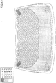
Fig. 12 . - As evident in
Figs. 4 to 13 , owing to the forming of slits in appropriate positions, it can be understood that the first to fourth samples were able to reduce the number of local regions of high temperature and significantly prevent the problem of local heating in comparison with the fifth sample having no slits formed. - In the sixth sample, the results of measuring antenna gain with slits formed in respective positions are described.
-
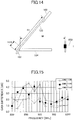
Fig. 14 is a diagram illustrating a position of a receiver antenna for measuring antenna gain according to the sixth example. InFig. 14 ,reference numeral 102 represents a window frame of an automobile,reference numeral 104 represents a dashboard of the automobile,reference numeral 120 represents a laminated glass,reference numeral 150 represents a receiver antenna, and reference numerals H1, H14, and M represent dimensions (mm). H1 is 801, H14 is 140, and M is 1000. - Antenna gain was measured by transmitting vertically polarized electromagnetic waves to the outside of the vehicle in a direction of the
laminated glass 120 placed on a horizontal turntable and assembled to thewindow frame 102 of the vehicle and receiving the electromagnetic waves transmitted through thelaminated glass 120 with thereceiver antenna 150 inside the vehicle. The tilt angle θ relative to a horizontal plane of thelaminated glass 120 was approximately 30 degrees. The tilt angle θ was measured at a center of thelaminated glass 120 in the vehicle width direction. The vehicle center of the automobile was positioned on a center rotation axis of the turntable. - A laminated glass including a copper foil serving as an alternative of the transparent conductive film, a glass plate, and an intermediate film, and a glass plate in this order was used as the
laminated glass 120. Further, a laminated glass having no bus bars was used as the laminated glass. The configuration of thelaminated glass 120 is the same except for the position in which the slit was formed in the copper foil. The configuration of thelaminated glass 120 is described mainly regarding the position of the slit. - Table 1 illustrates the position of the slit(s) formed in the copper foil. The
positions 1 to 7 indicated in Table 1 correspond to the positions of the seven slits illustrated inFig. 8 and are arranged in an ascending order from the top ofFig. 8 to the bottom ofFig. 8 . Theposition 1 corresponds to the uppermost position inFig. 8 . The slits ofpositions 1 to 7 are formed with dimensions corresponding to the slits illustrated inFig. 8 .[Table 1] NUMBER OF POSITION FORMED WITH SLIT CONDITION 1 No. 1, No. 3, No. 5 CONDITION 2 No. 2, No. 4, No. 6 CONDITION 3 No. 1, No. 3, No. 5, No. 7 CONDITION 4 No. 2, No. 4, No. 6, No. 7 CONDITION 5No. 1, No. 2, No. 3, No. 4, No. 5, No. 6 CONDITION 6No. 1, No. 2, No. 3, No. 4, No. 5, No. 6, No. 7 - A half-wave dipole antenna MP651B (manufactured by Anritsu Corp.) was used as the
receiver antenna 150 for receiving electromagnetic waves in a 800-1000 MHz frequency band used for mobile phones and the like, and a half-wave dipole antenna MA5612B2 (manufactured by Anritsu Corp.) was used as thereceiver antenna 150 for receiving electromagnetic waves in a 1700-1960 MHz frequency band. Thereceiver antenna 150 was connected to a network analyzer via a coaxial cable. An element of thereceiver antenna 150 was placed orthogonal to the ground in the center in the vehicle width direction. The position of thereceiver antenna 150 was set at the same height as the electromagnetic wave transmitting position relative to the ground (1080 mm). The elevation angle of the receiving position of thereceiver antenna 150 relative to the electromagnetic wave transmitting position was set to 0 degrees (assuming that the elevation angle for the direction parallel to the ground is 0 degrees and that the elevation angle for the zenith direction is 90 degrees). The horizontal distance M between the element of thereceiver antenna 150 and the front surface of thelaminated glass 120 of the outer side of the vehicle in the vehicle front/rear direction was approximately 1000 mm. - The data of antenna gain amounting to 120 degrees for each frequency of the electromagnetic waves were averaged by rotating the turntable in a range of ±60 degrees relative to a reference position and receiving the electromagnetic waves for each
single rotation angle 1° with thereceiver antenna 150. The reference position of the turntable is the position in which thereceiver antenna 150 is in the electromagnetic wave transmitting position in the front/rear direction of the vehicle. The measuring frequency of the antenna gain was every 20 MHz in each frequency band. The difference (G1-G2) between the antenna gain G1 (dB) for each condition in Table 1 and the antenna gain G2 (dB) for a case where no slit is formed in the copper foil is referred to as "gain difference". - Table 2 illustrates the average gain difference in each frequency band.
[Table 2] AVERAGE GAIN DIFFERENCE (dB) 800 MHz - 1000 MHz 1700 MHz - 1960 MHz CONDITION 1 1.1 0.6 CONDITION 2 1.1 0.6 CONDITION 3 1.4 0.7 CONDITION 4 1.4 0.7 CONDITION 52.0 1.6 CONDITION 62.4 1.8 -
Fig. 15 is a graph illustrating gain difference and frequency characteristics in a frequency band of 800 MHz to 1000 MHz underconditions Fig. 16 is a graph illustrating gain difference and frequency characteristics in a frequency band of 1700 MHz to 1960 MHz underconditions Figs. 15 and16 , the vertical axis represents "gain difference" whereas the horizontal axis represents "frequency". - According to Table 2,
Fig. 15 , andFig. 16 , it can be understood that antenna gain and electromagnetic wave transmittance improve by increasing the number of slits. For example, according to the comparison betweencondition 5 andcondition 6 illustrated in Table 2, the average gain difference in the 800 MHz - 1000 MHz frequency band improves 0.4 dB by adding a slit in position 7, and the average gain difference in the 1700 MHz - 1960 MHz frequency band improves 0.2 dB by adding a slit in position 7. Further, according to Table 2,Fig. 15 , andFig. 16 , it can be understood that influence due to the difference in the slit position is small. The slit may be arranged in a position that reduces the problem of local heating. - Although embodiments of a plate for an electro-thermal window have been described embodiment, the present invention are not limited to the above-described embodiments. Variations and modifications may be made without departing from the scope of the present invention.
- For example, the transparent
conductive film 12 of the above-described embodiment has an upper side that is shorter than its lower side as illustrated inFig. 1 . However, the upper side may be longer than the lower side. In this case, the bus bar distance becomes shorter from the upper side to the lower side. - Further, although the transparent
conductive film 12 of the above-described embodiment transmits vertically polarized waves, other waves such as horizontally polarized waves or circularly polarized waves may also be transmitted through the transparentconductive film 12. For example, the transparentconductive film 12 may include a slit parallel to the vertical direction for transmitting horizontally polarized waves therethrough. - Further, another region may be provided between the
first region 31 and thesecond region 32 illustrated inFig. 1 . The size difference between the bus bar distance of the other region and the bus bar distance of thefirst region 31 and the size difference between the vertical direction width of the other region and the vertical direction width of thefirst region 31 are not to be limited in particular. Similarly, the size difference between the bus bar distance of the other region and the bus bar distance of thesecond region 32 and the size difference between the vertical direction width of the other region and the vertical direction width of thesecond region 32 are not to be limited in particular. For example, in a case of a front glass for an automobile, the other region may be provided at the middle of the plate for awindow 11 in the vertical direction for ensuring the view of the driver. In this case, the vertical direction width of the other region may be formed with a longer width than the vertical direction width of thesecond region 32. - The present application is based on and claims the benefit of priority of Japanese Priority Application No.
2014-093110 filed on April 28, 2014 -
- 10
- plate for electro-thermal window
- 11
- plate for window
- 12
- transparent conductive film
- 13
- left bus bar
- 14
- right bus bar
- 21
- slit
- 31
- first region
- 32
- second region
Claims (6)
- A plate for an electro-thermal window comprising:a transparent conductive film that can be heated; anda plurality of bus bars that feed power to the transparent conductive film;wherein the plurality of bus bars include a left bus bar connected to a left side edge part of the transparent conductive film and a right bus bar connected to a right side edge part of the transparent conductive film,wherein the transparent conductive film is divided into a plurality of regions by a slit that is continuously or discontinuously formed from the left bus bar to the right bus bar,wherein the plurality of regions include a first region and a second region,wherein a distance between the left bus bar and the right bus bar of the first region is shorter than a distance between the left bus bar and the right bus bar of the second region, andwherein a width of the first region in a direction orthogonal to the slit is shorter than a width of the second region in the direction orthogonal to the slit.
- The plate for an electro-thermal window as claimed in claim 1, wherein the transparent conductive film is divided into three or more regions by a plurality of the slits.
- The plate for an electro-thermal window as claimed in claim 2, wherein among the three or more regions, the width of an region is shorter, the shorter the distance of the region.
- The plate for an electro-thermal window as claimed in claim 2, wherein among the three or more regions, the distance of a region is shorter, the shorter the width of the region.
- The plate for an electro-thermal window as claimed in one of claims 1 to 4, wherein the distance between the left bus bar and the right bus bar gradually becomes longer from an upper side to a lower side.
- The plate for an electro-thermal window as claimed in one of claims 2 to 5,
wherein the transparent conductive film, by way of the slit, forms a frequency selective surface through which a vertically polarized electromagnetic wave of a predetermined frequency band is transmitted,
wherein a wavelength of the plate for an electro-thermal window satisfies λg = λ0 × k
in a case where "λ0" is a wavelength of a center frequency in the predetermined frequency band in an atmosphere and "k" is a wavelength shortening rate of the plate for an electro-thermal window,
wherein an interval at least between a pair of adjacent slits is less than or equal to λg/4.
Applications Claiming Priority (2)
| Application Number | Priority Date | Filing Date | Title |
|---|---|---|---|
| JP2014093110 | 2014-04-28 | ||
| PCT/JP2015/057746 WO2015166735A1 (en) | 2014-04-28 | 2015-03-16 | Board-like body for electrically heated window |
Publications (3)
| Publication Number | Publication Date |
|---|---|
| EP3141439A1 true EP3141439A1 (en) | 2017-03-15 |
| EP3141439A4 EP3141439A4 (en) | 2018-04-04 |
| EP3141439B1 EP3141439B1 (en) | 2021-05-12 |
Family
ID=54358475
Family Applications (1)
| Application Number | Title | Priority Date | Filing Date |
|---|---|---|---|
| EP15786231.9A Active EP3141439B1 (en) | 2014-04-28 | 2015-03-16 | Plate for electro-thermal window |
Country Status (6)
| Country | Link |
|---|---|
| US (1) | US10597001B2 (en) |
| EP (1) | EP3141439B1 (en) |
| JP (2) | JPWO2015166735A1 (en) |
| CN (2) | CN106255627A (en) |
| RU (1) | RU2679642C2 (en) |
| WO (1) | WO2015166735A1 (en) |
Families Citing this family (10)
| Publication number | Priority date | Publication date | Assignee | Title |
|---|---|---|---|---|
| JP6607123B2 (en) * | 2016-03-30 | 2019-11-20 | 大日本印刷株式会社 | Glass plate with heating electrode and vehicle |
| FR3059939B1 (en) * | 2016-12-14 | 2019-01-25 | Saint-Gobain Glass France | LAMINATED GLAZING HAVING AN ELECTROCONDUCTIVE LAYER WITH ABLATION LINE WITH EDGES FREE OF BOURRELET AND SLOW SLOPE |
| CN106739988A (en) * | 2017-01-20 | 2017-05-31 | 大连七色光太阳能科技开发有限公司 | Electric heating car windshield |
| DE112019002709T5 (en) * | 2018-05-30 | 2021-03-11 | AGC Inc. | Glass |
| WO2019230732A1 (en) * | 2018-05-30 | 2019-12-05 | Agc株式会社 | Laminated glass |
| CN108973609B (en) * | 2018-07-16 | 2020-04-10 | 福耀玻璃工业集团股份有限公司 | Electric heating window glass capable of displaying light |
| CN112771719B (en) * | 2018-10-05 | 2024-03-29 | Agc株式会社 | Antenna system |
| DE102019128467A1 (en) * | 2019-10-22 | 2021-04-22 | Webasto SE | Electric heating devices, in particular for mobile applications |
| DE202022002766U1 (en) | 2021-04-09 | 2023-06-12 | Saint-Gobain Glass France | Electronic arrangement for several heated camera windows |
| WO2022214367A1 (en) | 2021-04-09 | 2022-10-13 | Saint-Gobain Glass France | Electronic assembly for multiple heatable camera windows |
Family Cites Families (43)
| Publication number | Priority date | Publication date | Assignee | Title |
|---|---|---|---|---|
| US2557983A (en) * | 1949-03-22 | 1951-06-26 | Pittsburgh Plate Glass Co | Transparent electroconductive article |
| US3366777A (en) * | 1967-01-16 | 1968-01-30 | Kenneth W. Brittan | Electrically heated window glazings |
| US3790745A (en) * | 1972-10-13 | 1974-02-05 | Sierracin Corp | Temperature control for electrically heatable window |
| US3982092A (en) * | 1974-09-06 | 1976-09-21 | Libbey-Owens-Ford Company | Electrically heated zoned window systems |
| GB8402244D0 (en) * | 1984-01-27 | 1984-02-29 | Pilkington Brothers Plc | Glass window |
| JPH066582Y2 (en) | 1988-03-31 | 1994-02-16 | 日本板硝子株式会社 | Car window glass antenna |
| JPH0325355U (en) | 1989-07-22 | 1991-03-15 | ||
| JP2526393B2 (en) * | 1991-07-12 | 1996-08-21 | 東京工業大学長 | Parallel plate slot antenna |
| JPH0584546U (en) * | 1992-04-21 | 1993-11-16 | 日本板硝子株式会社 | Window glass with conductive film for heat generation |
| US5466911A (en) * | 1993-07-06 | 1995-11-14 | Ford Motor Company | Window asssembly and method for electrically heating vehicle side lite |
| JP3458975B2 (en) * | 1993-12-28 | 2003-10-20 | マツダ株式会社 | Glass antenna for vehicle and setting method thereof |
| DE19503892C1 (en) | 1995-02-07 | 1996-10-24 | Sekurit Saint Gobain Deutsch | Car glass pane provided with an electrical conductive layer |
| DE19541609C2 (en) * | 1995-11-08 | 1998-02-19 | Sekurit Saint Gobain Deutsch | Electrically heated laminated glass for motor vehicles |
| US6130645A (en) * | 1998-01-14 | 2000-10-10 | Fuba Automotive Gmbh & Co. Kg | Combination wide band antenna and heating element on a window of a vehicle |
| DE29803544U1 (en) * | 1998-02-28 | 1998-04-23 | SEKURIT SAINT-GOBAIN Deutschland GmbH & Co. KG, 52066 Aachen | Electrically heated rear window made of laminated glass |
| JP2002020142A (en) * | 2000-06-29 | 2002-01-23 | Nippon Sheet Glass Co Ltd | Windshield for vehicle and method for manufacturing the same |
| GB0017415D0 (en) * | 2000-07-14 | 2000-08-30 | Bsh Ind Ltd | Antenna |
| US6559419B1 (en) | 2001-08-03 | 2003-05-06 | Centre Luxembourgeois De Recherches Pour Le Verre Et La Ceramique S.A. (C.R.V.C.) | Multi-zone arrangement for heatable vehicle window |
| GB0121118D0 (en) | 2001-08-31 | 2001-10-24 | Pilkington Plc | Electrically heated window |
| JP3994259B2 (en) * | 2001-12-06 | 2007-10-17 | 旭硝子株式会社 | Automotive window glass with conductive film and radio wave transmission / reception structure for automobile |
| WO2003055821A1 (en) * | 2001-12-25 | 2003-07-10 | Nippon Sheet Glass Company, Limited | Windshield glass |
| WO2003105533A1 (en) * | 2002-06-05 | 2003-12-18 | Glaverbel | Heatable glazing panel |
| AU2003255506A1 (en) * | 2002-06-05 | 2003-12-22 | Glaverbel | Heatable glazing panel |
| US7132625B2 (en) | 2002-10-03 | 2006-11-07 | Ppg Industries Ohio, Inc. | Heatable article having a configured heating member |
| US6860081B2 (en) * | 2002-12-04 | 2005-03-01 | The Ohio State University | Sidelobe controlled radio transmission region in metallic panel |
| US6891517B2 (en) * | 2003-04-08 | 2005-05-10 | Ppg Industries Ohio, Inc. | Conductive frequency selective surface utilizing arc and line elements |
| DE10333618B3 (en) | 2003-07-24 | 2005-03-24 | Saint-Gobain Sekurit Deutschland Gmbh & Co. Kg | Substrate with an electrically conductive coating and a communication window |
| CN1906803B (en) * | 2004-06-29 | 2011-05-25 | 日本板硝子株式会社 | Hot-wire pattern structure of defogger formed on vehicle-use rear glass and vehicle-use rear glass |
| JP2006310953A (en) * | 2005-04-26 | 2006-11-09 | Asahi Glass Co Ltd | High frequency glass antenna for automobile |
| DE102006002636B4 (en) * | 2006-01-19 | 2009-10-22 | Saint-Gobain Sekurit Deutschland Gmbh & Co. Kg | Tan-clear pane with a heatable layer system |
| GB0612698D0 (en) | 2006-06-27 | 2006-08-09 | Pilkington Plc | Heatable vehicle glazing |
| EP2151144A2 (en) * | 2007-04-27 | 2010-02-10 | Fraunhofer-Gesellschaft zur Förderung der angewandten Forschung e.V. | Headlight for a motor vehicle |
| JP5109089B2 (en) * | 2008-06-20 | 2012-12-26 | 旭硝子株式会社 | Glass antenna for vehicle and window glass for vehicle |
| US8288678B2 (en) * | 2008-12-18 | 2012-10-16 | Ppg Industries Ohio, Inc. | Device for and method of maintaining a constant distance between a cutting edge and a reference surface |
| EP2591638B1 (en) * | 2010-07-07 | 2016-10-19 | Saint-Gobain Glass France | Composite pane having an electrically heatable coating |
| EP2405708A1 (en) * | 2010-07-07 | 2012-01-11 | Saint-Gobain Glass France | Transparent plate with heatable coating |
| JP2014045230A (en) * | 2010-12-28 | 2014-03-13 | Asahi Glass Co Ltd | Antenna device |
| WO2012096540A2 (en) * | 2011-01-13 | 2012-07-19 | 주식회사 엘지화학 | Heating element and a production method therefor |
| JP2012217003A (en) * | 2011-03-31 | 2012-11-08 | Nippon Sheet Glass Co Ltd | Vehicle window glass |
| CN103477706B (en) * | 2011-04-12 | 2015-10-14 | 法国圣戈班玻璃厂 | Can electrically heated carrier and panel heater and preparation method thereof |
| EP3300452B8 (en) * | 2013-01-21 | 2022-02-23 | AGC Inc. | Electrically-heated window sheet material |
| EP3028534B1 (en) * | 2013-07-31 | 2021-12-15 | Saint-Gobain Glass France | Heatable laminated side window |
| US10165627B2 (en) * | 2013-10-15 | 2018-12-25 | Lg Chem, Ltd. | Heating element having communication window |
-
2015
- 2015-03-16 RU RU2016142181A patent/RU2679642C2/en active
- 2015-03-16 CN CN201580022265.4A patent/CN106255627A/en active Pending
- 2015-03-16 CN CN201910047464.0A patent/CN110027510B/en active Active
- 2015-03-16 JP JP2016515898A patent/JPWO2015166735A1/en not_active Withdrawn
- 2015-03-16 WO PCT/JP2015/057746 patent/WO2015166735A1/en not_active Ceased
- 2015-03-16 EP EP15786231.9A patent/EP3141439B1/en active Active
-
2016
- 2016-10-25 US US15/333,821 patent/US10597001B2/en active Active
-
2018
- 2018-11-16 JP JP2018215859A patent/JP6497480B1/en active Active
Also Published As
| Publication number | Publication date |
|---|---|
| RU2016142181A (en) | 2018-05-29 |
| US20170036646A1 (en) | 2017-02-09 |
| EP3141439A4 (en) | 2018-04-04 |
| JP6497480B1 (en) | 2019-04-10 |
| JP2019083196A (en) | 2019-05-30 |
| JPWO2015166735A1 (en) | 2017-04-20 |
| CN110027510A (en) | 2019-07-19 |
| RU2016142181A3 (en) | 2018-08-03 |
| RU2679642C2 (en) | 2019-02-12 |
| US10597001B2 (en) | 2020-03-24 |
| EP3141439B1 (en) | 2021-05-12 |
| CN110027510B (en) | 2022-05-10 |
| WO2015166735A1 (en) | 2015-11-05 |
| CN106255627A (en) | 2016-12-21 |
Similar Documents
| Publication | Publication Date | Title |
|---|---|---|
| EP3141439B1 (en) | Plate for electro-thermal window | |
| EP2980919B1 (en) | Windshield and antenna | |
| US10091840B2 (en) | Electrically-heated window sheet material | |
| US10211509B2 (en) | Vehicle window glass and antenna | |
| EP3235339B1 (en) | Electrically heatable antenna disc and method for producing same | |
| US10237922B2 (en) | Electrically-heated window sheet material | |
| CN107453029B (en) | window glass for vehicles | |
| JP2014033243A (en) | Vehicle window glass and antenna | |
| JP7605210B2 (en) | Vehicle window glass and vehicle structure | |
| US10721795B2 (en) | Window assembly comprising conductive transparent layer and conductive element implementing hybrid bus-bar/antenna | |
| US20170346154A1 (en) | Window glass for vehicle | |
| WO2014142312A1 (en) | Window glass for vehicle | |
| US20250279571A1 (en) | Window glass for vehicle | |
| JP2022117929A (en) | Vehicle window glass and vehicle window glass device | |
| JP2024004452A (en) | vehicle window glass | |
| DE112022004088T5 (en) | VEHICLE ANTENNA DEVICE | |
| JP2024020774A (en) | vehicle antenna | |
| WO2025249342A1 (en) | Vehicular window glass | |
| JP2014165685A (en) | Planar antenna for circularly polarized wave transmission/reception |
Legal Events
| Date | Code | Title | Description |
|---|---|---|---|
| STAA | Information on the status of an ep patent application or granted ep patent |
Free format text: STATUS: THE INTERNATIONAL PUBLICATION HAS BEEN MADE |
|
| PUAI | Public reference made under article 153(3) epc to a published international application that has entered the european phase |
Free format text: ORIGINAL CODE: 0009012 |
|
| STAA | Information on the status of an ep patent application or granted ep patent |
Free format text: STATUS: REQUEST FOR EXAMINATION WAS MADE |
|
| 17P | Request for examination filed |
Effective date: 20161026 |
|
| AK | Designated contracting states |
Kind code of ref document: A1 Designated state(s): AL AT BE BG CH CY CZ DE DK EE ES FI FR GB GR HR HU IE IS IT LI LT LU LV MC MK MT NL NO PL PT RO RS SE SI SK SM TR |
|
| AX | Request for extension of the european patent |
Extension state: BA ME |
|
| DAV | Request for validation of the european patent (deleted) | ||
| DAX | Request for extension of the european patent (deleted) | ||
| A4 | Supplementary search report drawn up and despatched |
Effective date: 20180302 |
|
| RIC1 | Information provided on ipc code assigned before grant |
Ipc: B60S 1/58 20060101ALI20180226BHEP Ipc: B60S 1/02 20060101AFI20180226BHEP |
|
| RAP1 | Party data changed (applicant data changed or rights of an application transferred) |
Owner name: AGC INC. |
|
| STAA | Information on the status of an ep patent application or granted ep patent |
Free format text: STATUS: EXAMINATION IS IN PROGRESS |
|
| 17Q | First examination report despatched |
Effective date: 20200303 |
|
| GRAP | Despatch of communication of intention to grant a patent |
Free format text: ORIGINAL CODE: EPIDOSNIGR1 |
|
| STAA | Information on the status of an ep patent application or granted ep patent |
Free format text: STATUS: GRANT OF PATENT IS INTENDED |
|
| INTG | Intention to grant announced |
Effective date: 20201112 |
|
| GRAS | Grant fee paid |
Free format text: ORIGINAL CODE: EPIDOSNIGR3 |
|
| GRAA | (expected) grant |
Free format text: ORIGINAL CODE: 0009210 |
|
| STAA | Information on the status of an ep patent application or granted ep patent |
Free format text: STATUS: THE PATENT HAS BEEN GRANTED |
|
| RIN1 | Information on inventor provided before grant (corrected) |
Inventor name: KAGAYA, OSAMU Inventor name: TOMINAGA, HIROMASA Inventor name: TAKAHASHI, TOMOHIRO |
|
| AK | Designated contracting states |
Kind code of ref document: B1 Designated state(s): AL AT BE BG CH CY CZ DE DK EE ES FI FR GB GR HR HU IE IS IT LI LT LU LV MC MK MT NL NO PL PT RO RS SE SI SK SM TR |
|
| REG | Reference to a national code |
Ref country code: GB Ref legal event code: FG4D |
|
| REG | Reference to a national code |
Ref country code: CH Ref legal event code: EP |
|
| REG | Reference to a national code |
Ref country code: DE Ref legal event code: R096 Ref document number: 602015069269 Country of ref document: DE |
|
| REG | Reference to a national code |
Ref country code: IE Ref legal event code: FG4D |
|
| REG | Reference to a national code |
Ref country code: AT Ref legal event code: REF Ref document number: 1391995 Country of ref document: AT Kind code of ref document: T Effective date: 20210615 |
|
| REG | Reference to a national code |
Ref country code: LT Ref legal event code: MG9D |
|
| REG | Reference to a national code |
Ref country code: AT Ref legal event code: MK05 Ref document number: 1391995 Country of ref document: AT Kind code of ref document: T Effective date: 20210512 |
|
| REG | Reference to a national code |
Ref country code: NL Ref legal event code: MP Effective date: 20210512 |
|
| PG25 | Lapsed in a contracting state [announced via postgrant information from national office to epo] |
Ref country code: LT Free format text: LAPSE BECAUSE OF FAILURE TO SUBMIT A TRANSLATION OF THE DESCRIPTION OR TO PAY THE FEE WITHIN THE PRESCRIBED TIME-LIMIT Effective date: 20210512 Ref country code: FI Free format text: LAPSE BECAUSE OF FAILURE TO SUBMIT A TRANSLATION OF THE DESCRIPTION OR TO PAY THE FEE WITHIN THE PRESCRIBED TIME-LIMIT Effective date: 20210512 Ref country code: HR Free format text: LAPSE BECAUSE OF FAILURE TO SUBMIT A TRANSLATION OF THE DESCRIPTION OR TO PAY THE FEE WITHIN THE PRESCRIBED TIME-LIMIT Effective date: 20210512 Ref country code: AT Free format text: LAPSE BECAUSE OF FAILURE TO SUBMIT A TRANSLATION OF THE DESCRIPTION OR TO PAY THE FEE WITHIN THE PRESCRIBED TIME-LIMIT Effective date: 20210512 Ref country code: BG Free format text: LAPSE BECAUSE OF FAILURE TO SUBMIT A TRANSLATION OF THE DESCRIPTION OR TO PAY THE FEE WITHIN THE PRESCRIBED TIME-LIMIT Effective date: 20210812 |
|
| PG25 | Lapsed in a contracting state [announced via postgrant information from national office to epo] |
Ref country code: GR Free format text: LAPSE BECAUSE OF FAILURE TO SUBMIT A TRANSLATION OF THE DESCRIPTION OR TO PAY THE FEE WITHIN THE PRESCRIBED TIME-LIMIT Effective date: 20210813 Ref country code: LV Free format text: LAPSE BECAUSE OF FAILURE TO SUBMIT A TRANSLATION OF THE DESCRIPTION OR TO PAY THE FEE WITHIN THE PRESCRIBED TIME-LIMIT Effective date: 20210512 Ref country code: IS Free format text: LAPSE BECAUSE OF FAILURE TO SUBMIT A TRANSLATION OF THE DESCRIPTION OR TO PAY THE FEE WITHIN THE PRESCRIBED TIME-LIMIT Effective date: 20210912 Ref country code: ES Free format text: LAPSE BECAUSE OF FAILURE TO SUBMIT A TRANSLATION OF THE DESCRIPTION OR TO PAY THE FEE WITHIN THE PRESCRIBED TIME-LIMIT Effective date: 20210512 Ref country code: PT Free format text: LAPSE BECAUSE OF FAILURE TO SUBMIT A TRANSLATION OF THE DESCRIPTION OR TO PAY THE FEE WITHIN THE PRESCRIBED TIME-LIMIT Effective date: 20210913 Ref country code: NO Free format text: LAPSE BECAUSE OF FAILURE TO SUBMIT A TRANSLATION OF THE DESCRIPTION OR TO PAY THE FEE WITHIN THE PRESCRIBED TIME-LIMIT Effective date: 20210812 Ref country code: PL Free format text: LAPSE BECAUSE OF FAILURE TO SUBMIT A TRANSLATION OF THE DESCRIPTION OR TO PAY THE FEE WITHIN THE PRESCRIBED TIME-LIMIT Effective date: 20210512 Ref country code: SE Free format text: LAPSE BECAUSE OF FAILURE TO SUBMIT A TRANSLATION OF THE DESCRIPTION OR TO PAY THE FEE WITHIN THE PRESCRIBED TIME-LIMIT Effective date: 20210512 Ref country code: RS Free format text: LAPSE BECAUSE OF FAILURE TO SUBMIT A TRANSLATION OF THE DESCRIPTION OR TO PAY THE FEE WITHIN THE PRESCRIBED TIME-LIMIT Effective date: 20210512 |
|
| PG25 | Lapsed in a contracting state [announced via postgrant information from national office to epo] |
Ref country code: NL Free format text: LAPSE BECAUSE OF FAILURE TO SUBMIT A TRANSLATION OF THE DESCRIPTION OR TO PAY THE FEE WITHIN THE PRESCRIBED TIME-LIMIT Effective date: 20210512 |
|
| PG25 | Lapsed in a contracting state [announced via postgrant information from national office to epo] |
Ref country code: RO Free format text: LAPSE BECAUSE OF FAILURE TO SUBMIT A TRANSLATION OF THE DESCRIPTION OR TO PAY THE FEE WITHIN THE PRESCRIBED TIME-LIMIT Effective date: 20210512 Ref country code: EE Free format text: LAPSE BECAUSE OF FAILURE TO SUBMIT A TRANSLATION OF THE DESCRIPTION OR TO PAY THE FEE WITHIN THE PRESCRIBED TIME-LIMIT Effective date: 20210512 Ref country code: CZ Free format text: LAPSE BECAUSE OF FAILURE TO SUBMIT A TRANSLATION OF THE DESCRIPTION OR TO PAY THE FEE WITHIN THE PRESCRIBED TIME-LIMIT Effective date: 20210512 Ref country code: DK Free format text: LAPSE BECAUSE OF FAILURE TO SUBMIT A TRANSLATION OF THE DESCRIPTION OR TO PAY THE FEE WITHIN THE PRESCRIBED TIME-LIMIT Effective date: 20210512 Ref country code: SK Free format text: LAPSE BECAUSE OF FAILURE TO SUBMIT A TRANSLATION OF THE DESCRIPTION OR TO PAY THE FEE WITHIN THE PRESCRIBED TIME-LIMIT Effective date: 20210512 Ref country code: SM Free format text: LAPSE BECAUSE OF FAILURE TO SUBMIT A TRANSLATION OF THE DESCRIPTION OR TO PAY THE FEE WITHIN THE PRESCRIBED TIME-LIMIT Effective date: 20210512 |
|
| REG | Reference to a national code |
Ref country code: DE Ref legal event code: R097 Ref document number: 602015069269 Country of ref document: DE |
|
| PLBE | No opposition filed within time limit |
Free format text: ORIGINAL CODE: 0009261 |
|
| STAA | Information on the status of an ep patent application or granted ep patent |
Free format text: STATUS: NO OPPOSITION FILED WITHIN TIME LIMIT |
|
| 26N | No opposition filed |
Effective date: 20220215 |
|
| PG25 | Lapsed in a contracting state [announced via postgrant information from national office to epo] |
Ref country code: IS Free format text: LAPSE BECAUSE OF FAILURE TO SUBMIT A TRANSLATION OF THE DESCRIPTION OR TO PAY THE FEE WITHIN THE PRESCRIBED TIME-LIMIT Effective date: 20210912 Ref country code: AL Free format text: LAPSE BECAUSE OF FAILURE TO SUBMIT A TRANSLATION OF THE DESCRIPTION OR TO PAY THE FEE WITHIN THE PRESCRIBED TIME-LIMIT Effective date: 20210512 |
|
| PG25 | Lapsed in a contracting state [announced via postgrant information from national office to epo] |
Ref country code: IT Free format text: LAPSE BECAUSE OF FAILURE TO SUBMIT A TRANSLATION OF THE DESCRIPTION OR TO PAY THE FEE WITHIN THE PRESCRIBED TIME-LIMIT Effective date: 20210512 |
|
| PG25 | Lapsed in a contracting state [announced via postgrant information from national office to epo] |
Ref country code: MC Free format text: LAPSE BECAUSE OF FAILURE TO SUBMIT A TRANSLATION OF THE DESCRIPTION OR TO PAY THE FEE WITHIN THE PRESCRIBED TIME-LIMIT Effective date: 20210512 |
|
| REG | Reference to a national code |
Ref country code: CH Ref legal event code: PL |
|
| GBPC | Gb: european patent ceased through non-payment of renewal fee |
Effective date: 20220316 |
|
| REG | Reference to a national code |
Ref country code: BE Ref legal event code: MM Effective date: 20220331 |
|
| PG25 | Lapsed in a contracting state [announced via postgrant information from national office to epo] |
Ref country code: LU Free format text: LAPSE BECAUSE OF NON-PAYMENT OF DUE FEES Effective date: 20220316 Ref country code: LI Free format text: LAPSE BECAUSE OF NON-PAYMENT OF DUE FEES Effective date: 20220331 Ref country code: IE Free format text: LAPSE BECAUSE OF NON-PAYMENT OF DUE FEES Effective date: 20220316 Ref country code: GB Free format text: LAPSE BECAUSE OF NON-PAYMENT OF DUE FEES Effective date: 20220316 Ref country code: FR Free format text: LAPSE BECAUSE OF NON-PAYMENT OF DUE FEES Effective date: 20220331 Ref country code: CH Free format text: LAPSE BECAUSE OF NON-PAYMENT OF DUE FEES Effective date: 20220331 |
|
| PG25 | Lapsed in a contracting state [announced via postgrant information from national office to epo] |
Ref country code: BE Free format text: LAPSE BECAUSE OF NON-PAYMENT OF DUE FEES Effective date: 20220331 |
|
| PG25 | Lapsed in a contracting state [announced via postgrant information from national office to epo] |
Ref country code: HU Free format text: LAPSE BECAUSE OF FAILURE TO SUBMIT A TRANSLATION OF THE DESCRIPTION OR TO PAY THE FEE WITHIN THE PRESCRIBED TIME-LIMIT; INVALID AB INITIO Effective date: 20150316 |
|
| PG25 | Lapsed in a contracting state [announced via postgrant information from national office to epo] |
Ref country code: MK Free format text: LAPSE BECAUSE OF FAILURE TO SUBMIT A TRANSLATION OF THE DESCRIPTION OR TO PAY THE FEE WITHIN THE PRESCRIBED TIME-LIMIT Effective date: 20210512 Ref country code: CY Free format text: LAPSE BECAUSE OF FAILURE TO SUBMIT A TRANSLATION OF THE DESCRIPTION OR TO PAY THE FEE WITHIN THE PRESCRIBED TIME-LIMIT Effective date: 20210512 |
|
| PG25 | Lapsed in a contracting state [announced via postgrant information from national office to epo] |
Ref country code: MT Free format text: LAPSE BECAUSE OF FAILURE TO SUBMIT A TRANSLATION OF THE DESCRIPTION OR TO PAY THE FEE WITHIN THE PRESCRIBED TIME-LIMIT Effective date: 20210512 |
|
| PG25 | Lapsed in a contracting state [announced via postgrant information from national office to epo] |
Ref country code: TR Free format text: LAPSE BECAUSE OF FAILURE TO SUBMIT A TRANSLATION OF THE DESCRIPTION OR TO PAY THE FEE WITHIN THE PRESCRIBED TIME-LIMIT Effective date: 20210512 |
|
| PGFP | Annual fee paid to national office [announced via postgrant information from national office to epo] |
Ref country code: DE Payment date: 20260319 Year of fee payment: 12 |