EP3141430A1 - System for the rotation of a rear view mirror frame - Google Patents
System for the rotation of a rear view mirror frame Download PDFInfo
- Publication number
- EP3141430A1 EP3141430A1 EP15872006.0A EP15872006A EP3141430A1 EP 3141430 A1 EP3141430 A1 EP 3141430A1 EP 15872006 A EP15872006 A EP 15872006A EP 3141430 A1 EP3141430 A1 EP 3141430A1
- Authority
- EP
- European Patent Office
- Prior art keywords
- motor
- worm
- casing
- crown wheel
- rear view
- Prior art date
- Legal status (The legal status is an assumption and is not a legal conclusion. Google has not performed a legal analysis and makes no representation as to the accuracy of the status listed.)
- Granted
Links
- 230000007246 mechanism Effects 0.000 claims abstract description 7
- 238000007373 indentation Methods 0.000 claims description 26
- 230000006866 deterioration Effects 0.000 description 3
- 230000009467 reduction Effects 0.000 description 3
- 239000011248 coating agent Substances 0.000 description 2
- 238000000576 coating method Methods 0.000 description 2
- 230000005540 biological transmission Effects 0.000 description 1
- 239000000969 carrier Substances 0.000 description 1
- 230000015556 catabolic process Effects 0.000 description 1
- 230000008859 change Effects 0.000 description 1
- 230000003247 decreasing effect Effects 0.000 description 1
- 230000007774 longterm Effects 0.000 description 1
- 238000000034 method Methods 0.000 description 1
- 230000008569 process Effects 0.000 description 1
Images



Classifications
-
- B—PERFORMING OPERATIONS; TRANSPORTING
- B60—VEHICLES IN GENERAL
- B60R—VEHICLES, VEHICLE FITTINGS, OR VEHICLE PARTS, NOT OTHERWISE PROVIDED FOR
- B60R1/00—Optical viewing arrangements; Real-time viewing arrangements for drivers or passengers using optical image capturing systems, e.g. cameras or video systems specially adapted for use in or on vehicles
- B60R1/02—Rear-view mirror arrangements
- B60R1/06—Rear-view mirror arrangements mounted on vehicle exterior
- B60R1/062—Rear-view mirror arrangements mounted on vehicle exterior with remote control for adjusting position
- B60R1/07—Rear-view mirror arrangements mounted on vehicle exterior with remote control for adjusting position by electrically powered actuators
- B60R1/074—Rear-view mirror arrangements mounted on vehicle exterior with remote control for adjusting position by electrically powered actuators for retracting the mirror arrangements to a non-use position alongside the vehicle
-
- F—MECHANICAL ENGINEERING; LIGHTING; HEATING; WEAPONS; BLASTING
- F16—ENGINEERING ELEMENTS AND UNITS; GENERAL MEASURES FOR PRODUCING AND MAINTAINING EFFECTIVE FUNCTIONING OF MACHINES OR INSTALLATIONS; THERMAL INSULATION IN GENERAL
- F16C—SHAFTS; FLEXIBLE SHAFTS; ELEMENTS OR CRANKSHAFT MECHANISMS; ROTARY BODIES OTHER THAN GEARING ELEMENTS; BEARINGS
- F16C17/00—Sliding-contact bearings for exclusively rotary movement
- F16C17/04—Sliding-contact bearings for exclusively rotary movement for axial load only
Definitions
- the present invention falls within the rear view mirror rotation system sector and, more specifically, the vehicle wing mirror sector.
- ES 2217986 presents a power fold for a vehicle external rear view mirrors which consists of a housed area, a supporting mirror carrier casing, and a removable crown wheel which operates as a rotation axis and is secured to the vehicle.
- the crown wheel is secured to the supporting frame and to a secondary supporting mechanism which, together with a stop element, a housed area and flexible parts, limits the rotation of the aforementioned carrier secured to the crown wheel and, dependant on rotational direction, includes a stop element and flexible parts integrated into one part with resilient properties.
- ES 2217986 does not address certain unresolved technical constraints, including rear view mirror rotation system durability and system operating noise throughout the mirror's deployment and retraction manoeuvres.
- the invention relates to a system for the rotation of a rear view mirror, as defined by patent claim 1.
- the dependant claims define the additional characteristics of the invention.
- the characteristics set forth in the patent claims both address and resolve certain issues which, to date, have received no solution on a technical level.
- This invention increases the durability and service life of a rear view mirror, improving the performance of the rotation system and providing a guarantee of improved long term functionality.
- noise resulting from the deterioration of system components is also reduced; effectively, the mechanical components are maintained in line with system specifications for a longer period as there is a reduction in system component backlash and misalignments: current systems are restricted to a minimum of 15,000 cycles. With the present invention's system, this number is increased to over 50,000 (one cycle is equivalent to one open and close). Additionally, functions are more refined from the start of service life than they are with current systems.
- Embodiment of the invention refers to the creation of a rear view mirror frame rotation system.
- the rear view mirror frame includes all elements necessary for protecting and externally manoeuvring the rear view mirror of a vehicle.
- the record of patent registry includes the following elements for transmission by means of two worms and two crown wheels: a worm motor (2), a crown wheel motor (3) with a geared worm motor (2); a worm drive (4), and a worm crown wheel motor (5) with a geared worm drive (4).
- the rear view mirror rotation system consists of:
- the rear view mirror rotation system may consist of:
- the seal (7) works by absorbing motor (1) length deviations as the tolerance of each dimension of the motor (1) length is offset, preventing knocks between the motor (1) and casing (6) throughout operation of the motor (1), reducing noise during rotation, and increasing durability of the motor (1), worm motor (2) and crown wheel motor (3) as the motor (1) is securely attached to the casing (6).
- the rear view mirror rotation system may consist of:
- the rear view mirror rotation system may consist of:
- the rear view mirror rotation system may consist of:
- the rear view mirror rotation system may consist of:
- the rear view mirror rotation system may consist of:
- the invention may consist of all or a combination of the aforementioned characteristics.
- the technical impact of the supporting plate (8) angular extensions (8A, 8B), casing (6) indentations (6R), supporting plate (8) projections (8P), supporting thickness (8E), casing (6) gears (6C', 6C", 6C”'), supporting plate (8) guides (8G', 8G", 8G''), positioner (6P) and housing (8H) is as follows:
- the aforementioned characteristics result in the improved functioning of all system components, ensuring there are no knocks between worms and crown wheels throughout operations.
- the first washer (11), second washer (12), spring washer (13) and seal (7) work together in worm motor (2) axial direction. These components cushion the axial thrust between the worm motor (2) and crown wheel motor (3).
- the plate (8) and casing (6) interact by means of the following elements: the supporting thickness (8E), the angular extensions (8A, 8B) of the supporting plate (8), casing (6) indentations (6R', 6R", 6R"', 6R”"), casing (6) gears (6C', 6C", 6C”'), supporting plate (8) projections (8P', 8P", 8P"', 8P”"), supporting plate (8) guides (8G', 8G", 8G”').
- the crown wheel drive (5) may be metallic.
- the crown wheel drive (5) may include an antifriction sleeve (5B).
- the rear view mirror rotation system may consist of:
- the drive shaft (34) may also consist of two additional secondary anti-friction sleeves (4B) for housing the supporting plate and casing. This initial antifriction sleeve (5B) results in improved crown drive (5) rotation, eliminating friction between fixed elements.
- the motor (1) may be encased so that the motor shaft only emerges from the enclosed area in the area containing the worm motor (2).
- the enclosed area for the motor (1) serves to regulate the axial load.
- the enclosed area for the motor (1) consists of a plate at the back of the motor (1) which controls the motor's axial movement.
- the shape of the worms and crown wheels results in a greater degree of coating which increases system performance by ensuring smoother functioning and reducing knocks and, subsequently, noise, throughout the process. Thanks to this increased coating, the force is also more evenly dispersed, increasing the service life of worms and crown wheels and, consequently, system durability, as these parts are critical for the correct functioning of the system and tend to suffer higher rates of deterioration and transmit greater force throughout operations.
Landscapes
- Engineering & Computer Science (AREA)
- Mechanical Engineering (AREA)
- Multimedia (AREA)
- General Engineering & Computer Science (AREA)
- Rear-View Mirror Devices That Are Mounted On The Exterior Of The Vehicle (AREA)
Abstract
Description
- The present invention falls within the rear view mirror rotation system sector and, more specifically, the vehicle wing mirror sector.
- Established power folds already exist for securing mirror carrier frames to external vehicle rear view mirrors, in the form of supporting plates that are fixed to the structure of a vehicle. Generally speaking, these modes of transport rely on detachable housed products fixed to mirror carriers which, essentially, consist of an electric motor and one or more gears that have been adapted to drive a rotation crown wheel connected to a supporting plate.
-
ES 2217986 - However,
ES 2217986 - The invention relates to a system for the rotation of a rear view mirror, as defined by
patent claim 1. The dependant claims define the additional characteristics of the invention. The characteristics set forth in the patent claims both address and resolve certain issues which, to date, have received no solution on a technical level. - This invention increases the durability and service life of a rear view mirror, improving the performance of the rotation system and providing a guarantee of improved long term functionality. By increasing the service life of the rotation system, noise resulting from the deterioration of system components is also reduced; effectively, the mechanical components are maintained in line with system specifications for a longer period as there is a reduction in system component backlash and misalignments: current systems are restricted to a minimum of 15,000 cycles. With the present invention's system, this number is increased to over 50,000 (one cycle is equivalent to one open and close). Additionally, functions are more refined from the start of service life than they are with current systems.
- In order to gain a better understanding, a series of drawings has been included in the present record of patent registry which, by way of example, represent the various characteristics of the invention.
-
Figure 1 is a cross section of the invention. -
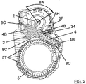
Figure 2 is a plan view of the invention. -
Figure 3 is a perspective view of the supporting plate, displaying the crown wheel motor and the worm drive. -
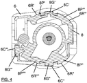
Figure 4 is a plan view displaying the supporting plate within its casing. -
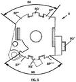
Figure 5 is a plan view of the invention's supporting plate. -
Figures 6A, 6B and 6C display the invention frame from various angles. -
- Drive motor (1)
- First washer (11)
- Second washer (12)
- Spring washer (13)
- Worm motor (2)
- Fillet motor (2T)
- Crown wheel motor (3)
- Motor teeth (3T)
- Worm drive (4)
- Fillet drive shaft (4T)
- Second worm drive (4) antifriction sleeve (4B)
- Drive shaft (34)
- Crown wheel drive (5)
- Toothed drive (5T)
- First worm drive (5) antifriction sleeve (5B)
- Casing (6)
- Casing (6) indentations (6R', 6R", 6R"', 6R"")
- Casing (6) gears (6C', 6C", 6C"')
- Positioner (6P)
- Seal (7)
- Supporting plate (8)
- Supporting plate (8) contact surface area (8S)
- Supporting plate (8) angular extensions (8A, 8B)
- Supporting plate (8) projections (8P', 8P", 8P"', 8P"")
- Plate thickness (8T)
- Support thickness (8E)
- Supporting plate (8) guides (8G', 8G", 8G"')
- Housing (8H)
- Seat (8C)
- Embodiment of the invention refers to the creation of a rear view mirror frame rotation system. The rear view mirror frame includes all elements necessary for protecting and externally manoeuvring the rear view mirror of a vehicle. The record of patent registry includes the following elements for transmission by means of two worms and two crown wheels: a worm motor (2), a crown wheel motor (3) with a geared worm motor (2); a worm drive (4), and a worm crown wheel motor (5) with a geared worm drive (4).
- The rear view mirror rotation system consists of:
- 1a) A drive motor (1);
- 1b) A worm motor (2), with a motor output shaft (1);
- 1c) A crown wheel motor (3), with a geared worm motor (2);
- 1d) A worm drive (4), coaxial with the crown wheel motor (3);
- 1e) A worm crown motor (5), with a geared worm drive (4), designed so that the rear view mirror can be manoeuvred between a retracted and deployed position.
- In
Figure 1 it is demonstrated that the rear view mirror frame rotation system consists of: - 1f) An anti-rebound mechanism between the motor (1) and worm motor (2); consisting of:
- 1f1) A first washer (11) attached to the motor (1);
- 1f2) A second washer (12) attached to the worm motor (2);
- 1f3) A spring washer (13), between the first (11) and second (12) washer; 1f3a) A configuration for cushioning the axial thrust between the worm motor (2) and the crown wheel motor (3).
- On a technical level, the anti-rebound mechanism results in:
- a reduction in noise during operation of the rotation system when the motor is inverted to change the rotation direction;
- decreased mechanical wear of engaged parts connected with the motor (1), namely the worm motor (2) and crown wheel motor (3), as the tangential force is cushioned in the fillet motor (2T) and motor teeth (3T); and
- an increase in durability of said parts, as the anti-rebound mechanism reduces the axial load relative to the motor shaft (1); significant axial loads can reduce the service life of connected parts.
- In compliance with the other characteristics of the invention, the rear view mirror rotation system may consist of:
- 2a) A casing (6), designed to house the motor (1);
- 2b) A seal (7), designed to cushion the motor (1) seat within the casing (6).
- The seal (7) works by absorbing motor (1) length deviations as the tolerance of each dimension of the motor (1) length is offset, preventing knocks between the motor (1) and casing (6) throughout operation of the motor (1), reducing noise during rotation, and increasing durability of the motor (1), worm motor (2) and crown wheel motor (3) as the motor (1) is securely attached to the casing (6).
- In compliance with the characteristics of the invention, the rear view mirror rotation system may consist of:
- 3a) a supporting plate (8):
- configured to:
- 3a1) Support the crown wheel motor (3) and worm motor (4);
- 3a2) Position the crown wheel motor (3) and worm motor (4) within the motor (1);
- 3a3) Support the casing (6) in order to position the motor (3) and worm motor (4), and guide the motor (1) within the casing (6);
- 3a4) Maintain contact surface area (8S) with the casing (6), including two angular extensions (8A, 8B) of over 75°.
Figure 2 demonstrates the first angular extension (8A) which defines the arc for the initial contact surface of the supporting plate (8) with the casing (6). In creating the invention displayed inFigure 5 , the first angular extension (8A) could be 93.1% and the second angular extension 78.5%. In total, for both areas, 47.6% of the total surface area of the cylinder.
- configured to:
- In compliance with the characteristics of the invention, the rear view mirror rotation system may consist of:
- 4a) A supporting plate (8):
- configured to:
- 4a1) Support the crown wheel motor (3) and worm motor (4);
- 4a2) Position the crown wheel motor (3) and worm motor (4);
- configured to:
- 4a3) Support the casing (6) in order to position the motor (3) and worm motor (4), and guide the motor (1) within the casing (6);
- where:
- 4b) The casing (6) consists of numerous indentations (6R', 6R", 6R"', 6R"") facing the supporting plate (8);
- 4c) The supporting plate (8) consists of numerous projections (8P', 8P", 8P"', 8P"") designed to fit into the indentations (6R', 6R", 6R"', 6R"").
Figure 4 is a plan view showing the supporting plate (8) within its casing (6).
Figure 4 shows the casing (6) indentations (6R', 6R", 6R"', 6R"") and supporting plate (8) projections (8P', 8P", 8P"', 8P""), slotted into the indentations (6R', 6R", 6R"', 6R""). In the embodiment shown inFigure 4 there are four pairs of indentations (6R', 6R", 6R"', 6R"")-projections (8P', 8P", 8P"', 8P""). The four pairs of indentations (6R', 6R", 6R"', 6R"")-projections (8P', 8P", 8P"', 8P"") detailed inFigure 4 can be grouped into two pairs. The first set groups the first pair of indentations (6R')-projections (8P') and the second pair of indentations (6R")-projections (8P"). The second set groups the third pair of indentations (6R"')-projections (8P"') and the fourth pair of indentations (6R"")-projections (8P""). InFigure 4 we can see that the first pair of indentations (6R')-projections (8P') is diametrically opposed to the second pair of indentations (6R")-projections (8P"). InFigure 4 we can also see that the third pair of indentations (6R"')-projections (8P"') is diametrically opposed to the fourth pair of indentations (6R"")-projections (8P"").
Figure 4 demonstrates that the four pairs of indentations (6R', 6R", 6R"', 6R"")-projections (8P', 8P", 8P"', 8P"") are distributed into two arcs diametrically opposed to the supporting plate (8). The first arc consists of the first pair of indentations (6R')-projections (8P') and the third pair of indentations (6R"')-projections (8P"'). The second arc consists of the second pair of indentations (6R")-projections (8P") and the fourth pair of indentations (6R"")-projections (8P"").
The total sum of all arcs connected to the supporting plate (8)-casing (6) for indentation pairs (6R', 6R", 6R"', 6R"")-projections (8P', 8P", 8P"', 8P"") is greater than 75°. If the preferred model for the invention is manufactured, the angle corresponding to the supporting plate (8)-casing (6) will be greater than 170°.Figure 5 displays the supporting plate (8) and projections (8P', 8P", 8P"', 8P"").Figures 6A, 6B and 6C display the casing (6) and indentations (6R', 6R", 6R"', 6R""). - In compliance with the characteristics of the invention, the rear view mirror rotation system may consist of:
- 5a) A supporting plate (8) with plate thickness (8T):
- configured to:
- 5a1) Support the crown wheel motor (3) and worm motor (4);
- 5a2) Position the crown wheel motor (3) and worm motor (4) within the motor (1);
- 5a3) Support the casing (6) in order to position the crown wheel motor (3) and worm motor (4), and guide the motor (1) within the casing (6);
- 5a4) Maintain contact surface area (8S) with the casing (6). Said area (8S) has a thickness (8E) greater than twice that of the plate (8T).
- configured to:
- In compliance with the characteristics of the invention, the rear view mirror rotation system may consist of:
- 6a) A supporting plate (8):
- configured to:
- 6a1) Support the crown wheel motor (3) and worm motor (4);
- 6a2) Position the crown wheel motor (3) and worm motor (4) within the motor (1);
- 6a3) Support the casing (6) in order to position the crown wheel motor (3), worm motor (4) and motor (1) within the casing (6);
- configured to:
- 6b) The casing (6) consists of numerous gears (6C', 6C", 6C'') parallel to a motor shaft (1);
- 6c) The supporting plate (8) consists of numerous guides (8G', 8G", 8G"') designed to fit into the gears (6C', 6C", 6C"').
Figure 4 is a plan view showing the supporting plate (8) within its casing (6). The supporting plate (8) ensures the crown wheel motor (3), worm motor (4) and, notably, the motor (1) are guided into position within the casing (6).Figure 4 shows the casing (6) gears (6C', 6C", 6C'') and supporting plate (8) guides (8G', 8G", 8G"') positioned in the gears (6C', 6C", 6C"'). In the embodiment shown inFigure 4 there are three pairs of gears (6C', 6C", 6C'")-guides (8G', 8G", 8G"'). The three pairs of gears (6C', 6C", 6C"')-guides (8G', 8G", 8G"') detailed inFigure 4 can be grouped into two sets. The first set groups two pairs of gears (6C', 6C")-guides (8G', 8G"). The second set groups the third pair of gears (6C"')-guides (8G"'). InFigure 4 it is demonstrated that the first pair of gears (6C')-guides (8G') for the first set are diametrically opposed to the second pair of gears (6C")-guides (8G") for the second set.
Figure 4 shows the distribution of the three pairs of gears (6C', 6C", 6C'")-guides (8G', 8G", 8G"'), where the main contact surface area of the supporting plate (8)-casing (6) for the third pair of gears (6C"')-guide (8G"') forms a 90° angle with the main surface contact area of the supporting plate (8)-casing (6) for the first pair of gears (6C')-guide (8G'), and the main surface contact area of the supporting plate (8)-casing (6) for the second pair of gears (6C")-guide (8G").Figure 5 shows the supporting plate (8) and guides (8G', 8G", 8G"'),Figures 6A, 6B and 6C show the casing (6) and gears (6C', 6C", 306C"'). - In compliance with the characteristics of the invention, the rear view mirror rotation system may consist of:
- 7a) A supporting plate (8):
- configured to:
- 7a1) Support the crown wheel motor (3) and worm motor (4);
- 7a2) Position the crown wheel motor (3) and worm motor (4) within the motor (1);
- 7a3) Support the casing (6) in order to position the motor (3), worm motor (4) and motor (1) within the casing (6);
- configured to:
- 7b) The casing (6) consists of a positioner (6P) facing the supporting plate (8);
- 7c) The supporting plate (8) includes a housing area (8H) for seating the positioner (6P)
- The invention may consist of all or a combination of the aforementioned characteristics. The technical impact of the supporting plate (8) angular extensions (8A, 8B), casing (6) indentations (6R), supporting plate (8) projections (8P), supporting thickness (8E), casing (6) gears (6C', 6C", 6C"'), supporting plate (8) guides (8G', 8G", 8G'''), positioner (6P) and housing (8H) is as follows:
- Reduced roll and pitch within the Supporting plate (8), motor (1), crown wheel motor (3) and worm drive (4);
- The plate (8) is securely attached to the casing (6) in order to control backlash in the various gears. This backlash is an important factor for the correct functioning of gears. All gears must have sufficient backlash in order to absorb axial run-out and maintain the shape of the teeth; insufficient backlash results in breakdowns due to overloading and excessive backlash may lead to deterioration as there is a reduction to the surface area contact force between the teeth-fillets (2T, 4T) and teeth (3T, 5T).
- The aforementioned characteristics result in the improved functioning of all system components, ensuring there are no knocks between worms and crown wheels throughout operations. The first washer (11), second washer (12), spring washer (13) and seal (7) work together in worm motor (2) axial direction. These components cushion the axial thrust between the worm motor (2) and crown wheel motor (3). The plate (8) and casing (6) interact by means of the following elements: the supporting thickness (8E), the angular extensions (8A, 8B) of the supporting plate (8), casing (6) indentations (6R', 6R", 6R"', 6R""), casing (6) gears (6C', 6C", 6C"'), supporting plate (8) projections (8P', 8P", 8P"', 8P""), supporting plate (8) guides (8G', 8G", 8G"').
- In compliance with other characteristics of the invention, the crown wheel drive (5) may be metallic.
- The technical impact of a metallic crown wheel is increased rotation system durability. In compliance with other characteristics of the invention, the crown wheel drive (5) may include an antifriction sleeve (5B).
- This initial antifriction sleeve (5B) results in improved rotation of the crown drive (5), eliminating friction between fixed elements. In compliance with the characteristics of the invention, the rear view mirror rotation system may consist of:
- 10a) A supporting plate (8):
- configured to:
- 10a1) Support the crown wheel motor (3) and worm motor (4);
- 10a2) Position the crown wheel motor (3) and worm motor (4) within the motor (1);
- 10a3) Support the casing (6) in order to position the motor (3), worm motor (4) and motor (1) within the casing (6);
- configured to:
- 10b) The crown wheel motor (3) is inserted into the drive shaft (34) of the worm drive (4);
- 10c) A selected element between the supporting plate (8), casing (6) and combinations therein, includes a seat (8C) designed to receive the drive shaft (34).
- 10d) The drive shaft (34) consists of a second anti-friction sleeve (4B) in the seat (8C).
- The drive shaft (34) may also consist of two additional secondary anti-friction sleeves (4B) for housing the supporting plate and casing. This initial antifriction sleeve (5B) results in improved crown drive (5) rotation, eliminating friction between fixed elements.
- In accordance with other characteristics of the invention, the motor (1) may be encased so that the motor shaft only emerges from the enclosed area in the area containing the worm motor (2).
- Ultimately, the enclosed area for the motor (1) serves to regulate the axial load. The enclosed area for the motor (1) consists of a plate at the back of the motor (1) which controls the motor's axial movement.
- In compliance with other invention characteristics:
- The worm motor (2) may include a trapezoidal fillet motor (2T)
- The crown wheel motor (3) may include evolving motor perforation (3T).
- The worm drive (4) may include a trapezoidal fillet drive shaft (4T).
- The crown wheel motor (5) may include an evolving drive perforation (3T).
- On a technical level, the shape of the worms and crown wheels results in a greater degree of coating which increases system performance by ensuring smoother functioning and reducing knocks and, subsequently, noise, throughout the process. Thanks to this increased coating, the force is also more evenly dispersed, increasing the service life of worms and crown wheels and, consequently, system durability, as these parts are critical for the correct functioning of the system and tend to suffer higher rates of deterioration and transmit greater force throughout operations.
Claims (15)
- Rear view mirror rotation system, consisting of:1a) A drive motor (1);1b) A worm motor (2), with a motor output shaft (1);1c) A crown wheel motor (3), with a geared worm motor (2);1d) A worm drive (4), coaxial with the crown wheel motor (3);1e) A worm crown motor (5), with a geared worm drive (4), designed so that the rear view mirror can be manoeuvred between a retracted and deployed positioncharacterised in that it comprises:1f) An anti-rebound mechanism between the motor (1) and worm motor (2); consisting of:1f1) A first washer (11) attached to the motor (1);1f2) A second washer (12) attached to the worm motor (2);1f3) A spring washer (13), between the first (11) and second (12) washer; 1f3a) Designed to cushion the axial thrust between the worm motor (2) and crown wheel motor (3).
- Rear view mirror rotation system, as per patent claim 1. characterised by comprising:2a) A casing (6) designed to house the motor (1);2b) A seal (7) designed to cushion the motor (1) in the casing (6).
- Rear view mirror rotation system, as per patent claim 2.
characterised in that it comprises:3a) A supporting plate (8):configured to:3a1) Support the crown wheel motor (3) and worm motor (4);3a2) Position the crown wheel motor (3) and worm motor (4) within the motor (1);3a3) Support the casing (6) in order to position the motor (3), worm motor (4) and motor (1) within the casing (6);3a4) Maintain contact surface area (8S) with the casing (6), including two angular extensions (8A, 8B) of over 75°. - Rear view mirror rotation system, as per claim.
characterised by comprising:4a) A supporting plate (8):configured to:where:4a1) Support the crown wheel motor (3) and worm motor (4);4a2) Position the crown wheel motor (3) and worm motor (4) within the motor (1);4a3) Support the casing (6) in order to position the motor (3), worm motor (4) and motor (1) within the casing (6);4b) The casing (6) consists of numerous indentations (6R', 6R", 6R"', 6R"") facing the supporting plate (8);4c) The supporting plate (8) consists of numerous projections (8P', 8P", 8P"', 8P"") designed to fit into the indentations (6R', 6R", 6R"', 6R""). - Rear view mirror rotation system, as per patent claim 2.
characterised in that it comprises:5a) A supporting plate (8) with plate thickness (8T):configured to:5a1) Support the crown wheel motor (3) and worm motor (4);5a2) Position the crown wheel motor (3) and worm motor (4) within the motor (1);5a3) Support the casing (6) in order to position the motor (3), worm motor (4) and motor (1) within the casing (6);5a4) Maintain contact surface area (8S) with the casing (6), with a thickness (8E) greater than twice that of the plate (8T). - Rear view mirror rotation system, as per patent claim 2.
characterised by comprising:6a) A supporting plate (8):configured to:where:6a1) Support the crown wheel motor (3) and worm motor (4);6a2) Position the crown wheel motor (3) and worm motor (4) within the motor (1);6a3) Support the casing (6) in order to position the crown wheel motor (3), worm motor (4) and motor (1) within the casing (6);6b) The casing (6) consists of numerous gears (6C', 6C", 6C"') parallel to a motor shaft (1);6c) The Supporting plate (8) consists of numerous guides (8G', 8G", 8G"') designed to fit into the gears (6C', 6C", 6C"'). - Rear view mirror rotation system, as per patent claim 2.
characterised in that it comprises:7a) A supporting plate (8):configured to:where:7a1) Support the crown wheel motor (3) and worm motor (4);7a2) Position the crown wheel motor (3) and worm motor (4) within the motor (1);7a3) Support the casing (6) in order to position the motor (3), worm motor (4) and motor (1) within the casing (6);7b) The casing (6) consists of a positioner (6P) facing the plate (8);7c) The supporting plate (8) includes a housed area (8H) for receiving the positioner (6P). - Rear view mirror rotation system, as per patent claim 1.
characterised in that it comprises:8a) A metallic crown drive (5). - Rear view mirror rotation system, as per patent claim 1.
characterised by comprising:9a) The crown drive (5) includes antifriction sleeve (5B). - Rear view mirror rotation system, as per patent claim.
characterised by comprisng:10a) A supporting plate (8):configured to:where:10a1) Support the crown wheel motor (3) and worm motor (4);10a2) Position the crown wheel motor (3) and worm motor (4) within the motor (1);10a3) Support the casing (6) in order to position the motor (3), worm motor (4) and motor (1) within the casing (6);10b) The crown wheel motor (3) is inserted into the drive shaft (34) of the worm drive (4);10c) A selected element between the supporting plate (8), the casing (6) and combinations therein, includes a seat (8C) designed to receive the drive shaft (34). - Rear view mirror rotation system, as per patent claim.
characterised in that it comprises:11a) The motor (1) is encased in such a way that the motor shaft only emerges from the enclosed area in the worm motor (2) area. - Rear view mirror rotation system, as per patent claim 1.
characterised by comprising:12a) The worm motor (2) includes a trapezoidal fillet motor (2T). - Rear view mirror rotation system, as per patent claim 1.
characterised in that it comprises:13a) The crown wheel motor (3) includes an evolving motor perforation (3T). - Rear view mirror rotation system, as per patent claim 1.
characterised by comprising:14a) The worm motor (4) includes a trapezoidal fillet motor (4T). - Rear view mirror rotation system, as per patent claim 1.
characterised in that it comprises:15a) The crown wheel (5) includes an evolving perforation driver (5T).
Applications Claiming Priority (2)
| Application Number | Priority Date | Filing Date | Title |
|---|---|---|---|
| ES201401033A ES2574819B1 (en) | 2014-12-22 | 2014-12-22 | Rearview mirror frame rotation systems |
| PCT/ES2015/070830 WO2016102724A1 (en) | 2014-12-22 | 2015-11-19 | System for the rotation of a rear view mirror frame |
Publications (3)
| Publication Number | Publication Date |
|---|---|
| EP3141430A1 true EP3141430A1 (en) | 2017-03-15 |
| EP3141430A4 EP3141430A4 (en) | 2018-01-17 |
| EP3141430B1 EP3141430B1 (en) | 2019-05-01 |
Family
ID=56125407
Family Applications (1)
| Application Number | Title | Priority Date | Filing Date |
|---|---|---|---|
| EP15872006.0A Not-in-force EP3141430B1 (en) | 2014-12-22 | 2015-11-19 | System for the rotation of a rear view mirror frame |
Country Status (3)
| Country | Link |
|---|---|
| EP (1) | EP3141430B1 (en) |
| ES (1) | ES2574819B1 (en) |
| WO (1) | WO2016102724A1 (en) |
Families Citing this family (1)
| Publication number | Priority date | Publication date | Assignee | Title |
|---|---|---|---|---|
| JP6605421B2 (en) * | 2016-09-20 | 2019-11-13 | 株式会社ホンダロック | Vehicle door mirror device |
Family Cites Families (7)
| Publication number | Priority date | Publication date | Assignee | Title |
|---|---|---|---|---|
| CH657725A5 (en) * | 1981-04-14 | 1986-09-15 | Papst Motoren Kg | ARRANGEMENT FOR SUPPRESSING AXIAL ROTOR VIBRATIONS IN AN ELECTRIC SMALL MOTOR. |
| US5369530A (en) * | 1990-10-24 | 1994-11-29 | Ichikoh Industries Ltd. | Stay housable type motor driven mirror |
| NL1019258C2 (en) * | 2001-10-30 | 2003-05-02 | Iku Holding Montfoort Bv | Fastening construction, in particular for an exterior mirror of a motor vehicle. |
| JP4395091B2 (en) * | 2005-03-25 | 2010-01-06 | 株式会社ホンダロック | Electric retractable mirror device |
| JP4441441B2 (en) * | 2005-05-06 | 2010-03-31 | 株式会社東海理化電機製作所 | Mirror device for vehicle |
| JP4676301B2 (en) * | 2005-10-14 | 2011-04-27 | 株式会社東海理化電機製作所 | Mirror device for vehicle |
| US7966904B2 (en) * | 2006-05-05 | 2011-06-28 | Questek Manufacturing Corporation | Low axial play drive system |
-
2014
- 2014-12-22 ES ES201401033A patent/ES2574819B1/en not_active Expired - Fee Related
-
2015
- 2015-11-19 WO PCT/ES2015/070830 patent/WO2016102724A1/en not_active Ceased
- 2015-11-19 EP EP15872006.0A patent/EP3141430B1/en not_active Not-in-force
Also Published As
| Publication number | Publication date |
|---|---|
| EP3141430A4 (en) | 2018-01-17 |
| ES2574819A1 (en) | 2016-06-22 |
| WO2016102724A1 (en) | 2016-06-30 |
| EP3141430B1 (en) | 2019-05-01 |
| ES2574819B1 (en) | 2016-11-02 |
Similar Documents
| Publication | Publication Date | Title |
|---|---|---|
| US9827879B2 (en) | Power seat slide device and vehicle seat | |
| JP5609977B2 (en) | Electric power steering device | |
| USRE37928E1 (en) | Recliner apparatus | |
| EP1101652B1 (en) | Reduction gear for vehicle seat | |
| US6871969B2 (en) | Speed reducer and electric retractable rearview mirror equipped with the speed reducer | |
| US9902324B2 (en) | Actuator mechanism for an adjustment device of a wing mirror and clutch assembly thereof | |
| US20180058556A1 (en) | A Gearbox Assembly for an Electric Power Steering Assembly | |
| CN103718432B (en) | Driver driving means | |
| EP3274242B1 (en) | A gearbox assembly for an electric power steering assembly | |
| CN101162037A (en) | Worm wheel transmission mechanism | |
| KR101684123B1 (en) | Folding seat actuator | |
| EP3085604A1 (en) | Vehicle rear wheel steering apparatus | |
| US20040149079A1 (en) | Actuator | |
| EP3750753B1 (en) | Rotary mechanism for display terminal, and vehicle | |
| CN107461457A (en) | Worm Gear Mechanism | |
| DE102015214426B4 (en) | Engine coupling device | |
| JP2019119386A (en) | Slide device | |
| EP3141430B1 (en) | System for the rotation of a rear view mirror frame | |
| EP0284807B1 (en) | Electric hoist | |
| KR102111294B1 (en) | Steer-by-wire type power steering apparatus | |
| SE538967C2 (en) | Electric power tool | |
| KR20140145340A (en) | Planetary Gear Apparatus | |
| US7735927B2 (en) | Anti-backlash resistant gearing for a seat mechanism | |
| JP6665663B2 (en) | Gear reducer | |
| JP2017067217A (en) | Clutch device |
Legal Events
| Date | Code | Title | Description |
|---|---|---|---|
| STAA | Information on the status of an ep patent application or granted ep patent |
Free format text: STATUS: THE INTERNATIONAL PUBLICATION HAS BEEN MADE |
|
| PUAI | Public reference made under article 153(3) epc to a published international application that has entered the european phase |
Free format text: ORIGINAL CODE: 0009012 |
|
| STAA | Information on the status of an ep patent application or granted ep patent |
Free format text: STATUS: REQUEST FOR EXAMINATION WAS MADE |
|
| 17P | Request for examination filed |
Effective date: 20161130 |
|
| AK | Designated contracting states |
Kind code of ref document: A1 Designated state(s): AL AT BE BG CH CY CZ DE DK EE ES FI FR GB GR HR HU IE IS IT LI LT LU LV MC MK MT NL NO PL PT RO RS SE SI SK SM TR |
|
| AX | Request for extension of the european patent |
Extension state: BA ME |
|
| A4 | Supplementary search report drawn up and despatched |
Effective date: 20171218 |
|
| RIC1 | Information provided on ipc code assigned before grant |
Ipc: B60R 1/074 20060101AFI20171212BHEP Ipc: F16C 17/04 20060101ALI20171212BHEP |
|
| DAV | Request for validation of the european patent (deleted) | ||
| DAX | Request for extension of the european patent (deleted) | ||
| STAA | Information on the status of an ep patent application or granted ep patent |
Free format text: STATUS: EXAMINATION IS IN PROGRESS |
|
| 17Q | First examination report despatched |
Effective date: 20181010 |
|
| GRAP | Despatch of communication of intention to grant a patent |
Free format text: ORIGINAL CODE: EPIDOSNIGR1 |
|
| STAA | Information on the status of an ep patent application or granted ep patent |
Free format text: STATUS: GRANT OF PATENT IS INTENDED |
|
| GRAS | Grant fee paid |
Free format text: ORIGINAL CODE: EPIDOSNIGR3 |
|
| INTG | Intention to grant announced |
Effective date: 20190225 |
|
| GRAA | (expected) grant |
Free format text: ORIGINAL CODE: 0009210 |
|
| STAA | Information on the status of an ep patent application or granted ep patent |
Free format text: STATUS: THE PATENT HAS BEEN GRANTED |
|
| AK | Designated contracting states |
Kind code of ref document: B1 Designated state(s): AL AT BE BG CH CY CZ DE DK EE ES FI FR GB GR HR HU IE IS IT LI LT LU LV MC MK MT NL NO PL PT RO RS SE SI SK SM TR |
|
| REG | Reference to a national code |
Ref country code: GB Ref legal event code: FG4D |
|
| REG | Reference to a national code |
Ref country code: CH Ref legal event code: EP Ref country code: AT Ref legal event code: REF Ref document number: 1126492 Country of ref document: AT Kind code of ref document: T Effective date: 20190515 |
|
| REG | Reference to a national code |
Ref country code: DE Ref legal event code: R096 Ref document number: 602015029577 Country of ref document: DE |
|
| REG | Reference to a national code |
Ref country code: IE Ref legal event code: FG4D |
|
| REG | Reference to a national code |
Ref country code: NL Ref legal event code: MP Effective date: 20190501 |
|
| REG | Reference to a national code |
Ref country code: LT Ref legal event code: MG4D |
|
| PG25 | Lapsed in a contracting state [announced via postgrant information from national office to epo] |
Ref country code: SE Free format text: LAPSE BECAUSE OF FAILURE TO SUBMIT A TRANSLATION OF THE DESCRIPTION OR TO PAY THE FEE WITHIN THE PRESCRIBED TIME-LIMIT Effective date: 20190501 Ref country code: ES Free format text: LAPSE BECAUSE OF FAILURE TO SUBMIT A TRANSLATION OF THE DESCRIPTION OR TO PAY THE FEE WITHIN THE PRESCRIBED TIME-LIMIT Effective date: 20190501 Ref country code: PT Free format text: LAPSE BECAUSE OF FAILURE TO SUBMIT A TRANSLATION OF THE DESCRIPTION OR TO PAY THE FEE WITHIN THE PRESCRIBED TIME-LIMIT Effective date: 20190901 Ref country code: LT Free format text: LAPSE BECAUSE OF FAILURE TO SUBMIT A TRANSLATION OF THE DESCRIPTION OR TO PAY THE FEE WITHIN THE PRESCRIBED TIME-LIMIT Effective date: 20190501 Ref country code: NL Free format text: LAPSE BECAUSE OF FAILURE TO SUBMIT A TRANSLATION OF THE DESCRIPTION OR TO PAY THE FEE WITHIN THE PRESCRIBED TIME-LIMIT Effective date: 20190501 Ref country code: FI Free format text: LAPSE BECAUSE OF FAILURE TO SUBMIT A TRANSLATION OF THE DESCRIPTION OR TO PAY THE FEE WITHIN THE PRESCRIBED TIME-LIMIT Effective date: 20190501 Ref country code: AL Free format text: LAPSE BECAUSE OF FAILURE TO SUBMIT A TRANSLATION OF THE DESCRIPTION OR TO PAY THE FEE WITHIN THE PRESCRIBED TIME-LIMIT Effective date: 20190501 Ref country code: NO Free format text: LAPSE BECAUSE OF FAILURE TO SUBMIT A TRANSLATION OF THE DESCRIPTION OR TO PAY THE FEE WITHIN THE PRESCRIBED TIME-LIMIT Effective date: 20190801 Ref country code: HR Free format text: LAPSE BECAUSE OF FAILURE TO SUBMIT A TRANSLATION OF THE DESCRIPTION OR TO PAY THE FEE WITHIN THE PRESCRIBED TIME-LIMIT Effective date: 20190501 |
|
| PG25 | Lapsed in a contracting state [announced via postgrant information from national office to epo] |
Ref country code: GR Free format text: LAPSE BECAUSE OF FAILURE TO SUBMIT A TRANSLATION OF THE DESCRIPTION OR TO PAY THE FEE WITHIN THE PRESCRIBED TIME-LIMIT Effective date: 20190802 Ref country code: LV Free format text: LAPSE BECAUSE OF FAILURE TO SUBMIT A TRANSLATION OF THE DESCRIPTION OR TO PAY THE FEE WITHIN THE PRESCRIBED TIME-LIMIT Effective date: 20190501 Ref country code: BG Free format text: LAPSE BECAUSE OF FAILURE TO SUBMIT A TRANSLATION OF THE DESCRIPTION OR TO PAY THE FEE WITHIN THE PRESCRIBED TIME-LIMIT Effective date: 20190801 Ref country code: RS Free format text: LAPSE BECAUSE OF FAILURE TO SUBMIT A TRANSLATION OF THE DESCRIPTION OR TO PAY THE FEE WITHIN THE PRESCRIBED TIME-LIMIT Effective date: 20190501 |
|
| REG | Reference to a national code |
Ref country code: AT Ref legal event code: MK05 Ref document number: 1126492 Country of ref document: AT Kind code of ref document: T Effective date: 20190501 |
|
| PG25 | Lapsed in a contracting state [announced via postgrant information from national office to epo] |
Ref country code: IS Free format text: LAPSE BECAUSE OF FAILURE TO SUBMIT A TRANSLATION OF THE DESCRIPTION OR TO PAY THE FEE WITHIN THE PRESCRIBED TIME-LIMIT Effective date: 20190901 |
|
| PG25 | Lapsed in a contracting state [announced via postgrant information from national office to epo] |
Ref country code: DK Free format text: LAPSE BECAUSE OF FAILURE TO SUBMIT A TRANSLATION OF THE DESCRIPTION OR TO PAY THE FEE WITHIN THE PRESCRIBED TIME-LIMIT Effective date: 20190501 Ref country code: AT Free format text: LAPSE BECAUSE OF FAILURE TO SUBMIT A TRANSLATION OF THE DESCRIPTION OR TO PAY THE FEE WITHIN THE PRESCRIBED TIME-LIMIT Effective date: 20190501 Ref country code: EE Free format text: LAPSE BECAUSE OF FAILURE TO SUBMIT A TRANSLATION OF THE DESCRIPTION OR TO PAY THE FEE WITHIN THE PRESCRIBED TIME-LIMIT Effective date: 20190501 Ref country code: RO Free format text: LAPSE BECAUSE OF FAILURE TO SUBMIT A TRANSLATION OF THE DESCRIPTION OR TO PAY THE FEE WITHIN THE PRESCRIBED TIME-LIMIT Effective date: 20190501 Ref country code: CZ Free format text: LAPSE BECAUSE OF FAILURE TO SUBMIT A TRANSLATION OF THE DESCRIPTION OR TO PAY THE FEE WITHIN THE PRESCRIBED TIME-LIMIT Effective date: 20190501 Ref country code: SK Free format text: LAPSE BECAUSE OF FAILURE TO SUBMIT A TRANSLATION OF THE DESCRIPTION OR TO PAY THE FEE WITHIN THE PRESCRIBED TIME-LIMIT Effective date: 20190501 |
|
| REG | Reference to a national code |
Ref country code: DE Ref legal event code: R097 Ref document number: 602015029577 Country of ref document: DE |
|
| PG25 | Lapsed in a contracting state [announced via postgrant information from national office to epo] |
Ref country code: SM Free format text: LAPSE BECAUSE OF FAILURE TO SUBMIT A TRANSLATION OF THE DESCRIPTION OR TO PAY THE FEE WITHIN THE PRESCRIBED TIME-LIMIT Effective date: 20190501 Ref country code: IT Free format text: LAPSE BECAUSE OF FAILURE TO SUBMIT A TRANSLATION OF THE DESCRIPTION OR TO PAY THE FEE WITHIN THE PRESCRIBED TIME-LIMIT Effective date: 20190501 |
|
| PLBE | No opposition filed within time limit |
Free format text: ORIGINAL CODE: 0009261 |
|
| STAA | Information on the status of an ep patent application or granted ep patent |
Free format text: STATUS: NO OPPOSITION FILED WITHIN TIME LIMIT |
|
| PG25 | Lapsed in a contracting state [announced via postgrant information from national office to epo] |
Ref country code: TR Free format text: LAPSE BECAUSE OF FAILURE TO SUBMIT A TRANSLATION OF THE DESCRIPTION OR TO PAY THE FEE WITHIN THE PRESCRIBED TIME-LIMIT Effective date: 20190501 |
|
| 26N | No opposition filed |
Effective date: 20200204 |
|
| PG25 | Lapsed in a contracting state [announced via postgrant information from national office to epo] |
Ref country code: PL Free format text: LAPSE BECAUSE OF FAILURE TO SUBMIT A TRANSLATION OF THE DESCRIPTION OR TO PAY THE FEE WITHIN THE PRESCRIBED TIME-LIMIT Effective date: 20190501 |
|
| PG25 | Lapsed in a contracting state [announced via postgrant information from national office to epo] |
Ref country code: SI Free format text: LAPSE BECAUSE OF FAILURE TO SUBMIT A TRANSLATION OF THE DESCRIPTION OR TO PAY THE FEE WITHIN THE PRESCRIBED TIME-LIMIT Effective date: 20190501 |
|
| REG | Reference to a national code |
Ref country code: DE Ref legal event code: R119 Ref document number: 602015029577 Country of ref document: DE |
|
| REG | Reference to a national code |
Ref country code: CH Ref legal event code: PL |
|
| PG25 | Lapsed in a contracting state [announced via postgrant information from national office to epo] |
Ref country code: CH Free format text: LAPSE BECAUSE OF NON-PAYMENT OF DUE FEES Effective date: 20191130 Ref country code: LU Free format text: LAPSE BECAUSE OF NON-PAYMENT OF DUE FEES Effective date: 20191119 Ref country code: LI Free format text: LAPSE BECAUSE OF NON-PAYMENT OF DUE FEES Effective date: 20191130 Ref country code: MC Free format text: LAPSE BECAUSE OF FAILURE TO SUBMIT A TRANSLATION OF THE DESCRIPTION OR TO PAY THE FEE WITHIN THE PRESCRIBED TIME-LIMIT Effective date: 20190501 |
|
| REG | Reference to a national code |
Ref country code: BE Ref legal event code: MM Effective date: 20191130 |
|
| GBPC | Gb: european patent ceased through non-payment of renewal fee |
Effective date: 20191119 |
|
| PG25 | Lapsed in a contracting state [announced via postgrant information from national office to epo] |
Ref country code: FR Free format text: LAPSE BECAUSE OF NON-PAYMENT OF DUE FEES Effective date: 20191130 Ref country code: GB Free format text: LAPSE BECAUSE OF NON-PAYMENT OF DUE FEES Effective date: 20191119 Ref country code: IE Free format text: LAPSE BECAUSE OF NON-PAYMENT OF DUE FEES Effective date: 20191119 Ref country code: DE Free format text: LAPSE BECAUSE OF NON-PAYMENT OF DUE FEES Effective date: 20200603 |
|
| PG25 | Lapsed in a contracting state [announced via postgrant information from national office to epo] |
Ref country code: BE Free format text: LAPSE BECAUSE OF NON-PAYMENT OF DUE FEES Effective date: 20191130 |
|
| PG25 | Lapsed in a contracting state [announced via postgrant information from national office to epo] |
Ref country code: CY Free format text: LAPSE BECAUSE OF FAILURE TO SUBMIT A TRANSLATION OF THE DESCRIPTION OR TO PAY THE FEE WITHIN THE PRESCRIBED TIME-LIMIT Effective date: 20190501 |
|
| PG25 | Lapsed in a contracting state [announced via postgrant information from national office to epo] |
Ref country code: HU Free format text: LAPSE BECAUSE OF FAILURE TO SUBMIT A TRANSLATION OF THE DESCRIPTION OR TO PAY THE FEE WITHIN THE PRESCRIBED TIME-LIMIT; INVALID AB INITIO Effective date: 20151119 Ref country code: MT Free format text: LAPSE BECAUSE OF FAILURE TO SUBMIT A TRANSLATION OF THE DESCRIPTION OR TO PAY THE FEE WITHIN THE PRESCRIBED TIME-LIMIT Effective date: 20190501 |
|
| PG25 | Lapsed in a contracting state [announced via postgrant information from national office to epo] |
Ref country code: MK Free format text: LAPSE BECAUSE OF FAILURE TO SUBMIT A TRANSLATION OF THE DESCRIPTION OR TO PAY THE FEE WITHIN THE PRESCRIBED TIME-LIMIT Effective date: 20190501 |