EP3141382A1 - Cylindrical-member molding method and device - Google Patents
Cylindrical-member molding method and device Download PDFInfo
- Publication number
- EP3141382A1 EP3141382A1 EP15789267.0A EP15789267A EP3141382A1 EP 3141382 A1 EP3141382 A1 EP 3141382A1 EP 15789267 A EP15789267 A EP 15789267A EP 3141382 A1 EP3141382 A1 EP 3141382A1
- Authority
- EP
- European Patent Office
- Prior art keywords
- belt
- reference line
- drum
- forming
- cylindrical
- Prior art date
- Legal status (The legal status is an assumption and is not a legal conclusion. Google has not performed a legal analysis and makes no representation as to the accuracy of the status listed.)
- Granted
Links
Images

Classifications
-
- B—PERFORMING OPERATIONS; TRANSPORTING
- B29—WORKING OF PLASTICS; WORKING OF SUBSTANCES IN A PLASTIC STATE IN GENERAL
- B29D—PRODUCING PARTICULAR ARTICLES FROM PLASTICS OR FROM SUBSTANCES IN A PLASTIC STATE
- B29D30/00—Producing pneumatic or solid tyres or parts thereof
- B29D30/06—Pneumatic tyres or parts thereof (e.g. produced by casting, moulding, compression moulding, injection moulding, centrifugal casting)
- B29D30/08—Building tyres
- B29D30/20—Building tyres by the flat-tyre method, i.e. building on cylindrical drums
- B29D30/30—Applying the layers; Guiding or stretching the layers during application
-
- B—PERFORMING OPERATIONS; TRANSPORTING
- B29—WORKING OF PLASTICS; WORKING OF SUBSTANCES IN A PLASTIC STATE IN GENERAL
- B29D—PRODUCING PARTICULAR ARTICLES FROM PLASTICS OR FROM SUBSTANCES IN A PLASTIC STATE
- B29D30/00—Producing pneumatic or solid tyres or parts thereof
- B29D30/06—Pneumatic tyres or parts thereof (e.g. produced by casting, moulding, compression moulding, injection moulding, centrifugal casting)
- B29D30/08—Building tyres
- B29D30/20—Building tyres by the flat-tyre method, i.e. building on cylindrical drums
- B29D30/24—Drums
- B29D30/26—Accessories or details, e.g. membranes, transfer rings
-
- B—PERFORMING OPERATIONS; TRANSPORTING
- B29—WORKING OF PLASTICS; WORKING OF SUBSTANCES IN A PLASTIC STATE IN GENERAL
- B29D—PRODUCING PARTICULAR ARTICLES FROM PLASTICS OR FROM SUBSTANCES IN A PLASTIC STATE
- B29D30/00—Producing pneumatic or solid tyres or parts thereof
- B29D30/06—Pneumatic tyres or parts thereof (e.g. produced by casting, moulding, compression moulding, injection moulding, centrifugal casting)
- B29D30/08—Building tyres
- B29D30/20—Building tyres by the flat-tyre method, i.e. building on cylindrical drums
- B29D30/30—Applying the layers; Guiding or stretching the layers during application
- B29D2030/3064—Details, accessories and auxiliary operations not otherwise provided for
-
- B—PERFORMING OPERATIONS; TRANSPORTING
- B29—WORKING OF PLASTICS; WORKING OF SUBSTANCES IN A PLASTIC STATE IN GENERAL
- B29D—PRODUCING PARTICULAR ARTICLES FROM PLASTICS OR FROM SUBSTANCES IN A PLASTIC STATE
- B29D30/00—Producing pneumatic or solid tyres or parts thereof
- B29D30/06—Pneumatic tyres or parts thereof (e.g. produced by casting, moulding, compression moulding, injection moulding, centrifugal casting)
- B29D30/08—Building tyres
- B29D30/20—Building tyres by the flat-tyre method, i.e. building on cylindrical drums
- B29D30/30—Applying the layers; Guiding or stretching the layers during application
- B29D30/3007—Applying the layers; Guiding or stretching the layers during application by feeding a sheet perpendicular to the drum axis and joining the ends to form an annular element
Definitions
- the present invention relates to a method and device for forming a cylindrical member, and more particularly, to a method and device for forming a cylindrical member which can accurately form belt-like members into a cylindrical shape without meandering.
- a belt-like belt member made of a plurality of steel cords disposed side by side at a predetermined cord angle and covered with a rubber is used.
- the belt member is formed by cutting disposed steel cords side by side covered with a rubber at the predetermined angle set in accordance with the cord angle at a predetermined length, and bonding together the plurality of members that are cut (for example, see Patent Document 1).
- the belt-like belt member is wound around a forming drum and formed in a cylindrical shape. Further, a tread rubber forming a tire tread is formed cylindrically by a belt-like unvulcanized rubber being wound around the forming drum.
- Patent Document 1 Japanese Unexamined Patent Application Publication No. 2009-226817A
- An object of the present invention is to provide a method and device for forming a cylindrical member in which belt-like members can be accurately formed into a cylindrical shape without meandering.
- a method of forming a cylindrical member to achieve the above object of the present invention is a method of forming a cylindrical member by transporting a belt-like member placed on a transport conveyor belt to a forming drum and winding the belt-like member around the forming drum to form the belt-like member in a cylindrical shape, the method including the steps of: detecting a position of a member reference line by a pre-winding position sensor before winding the belt-like member around the forming drum, the member reference line extending in a longitudinal direction of the belt-like member along the entire length of the belt-like member in the longitudinal direction thereof; and forming the belt-like member in a cylindrical shape by winding the belt-like member around the forming drum while the forming drum is relatively moved in a drum width direction with respect to the transport conveyor belt by a controller and the member reference line and a drum reference line are matched, on the basis of detection data by the pre-winding position sensor and position data of the drum reference line orthogonal to a drum axial center of the forming drum
- a forming device for forming a cylindrical member of the present invention is a forming device for forming a cylindrical member including a transport conveyor belt that transports a belt-like member placed thereon and a forming drum that winds the belt-like member that is transported to form the belt-like member in a cylindrical shape.
- the forming device includes a pre-winding position sensor that detects a position of a member reference line extending in a longitudinal direction of the belt-like member, placed on the transport conveyor belt, along the entire length of the belt-like member in the longitudinal direction thereof; and a controller to which the data detected by the pre-winding position sensor is input.
- the belt-like member is formed in a cylindrical shape by winding the belt-like member around the forming drum while the forming drum is relatively moved in a drum width direction with respect to the transport conveyor belt by the controller and the member reference line and a drum reference line are matched, on the basis of detection data by the pre-winding position sensor and position data of the drum reference line orthogonal to a drum axial center of the forming drum and set in a predetermined position of the drum width direction, the position data of the drum reference line being previously input to the controller.
- the belt-like member can be accurately formed in a cylindrical shape without meandering, because the belt-like member is wound around the forming drum and formed in a cylindrical shape while the forming drum is relatively moved in the drum width direction with respect to the transport conveyor belt by the controller and the member reference line and the drum reference line are matched, on the basis of the position data of the member reference line drawn on the belt-like member placed on the transport conveyor belt and the position data of the drum reference line orthogonal to the drum axial center of the forming drum and set in the predetermined position in the drum width direction.
- manufacturing tires using the above formed cylindrical member can have consistent quality.
- the pre-winding position sensor detects a position of a member reference line before winding the other belt-like member around the outer peripheral surface of the cylindrical member, the member reference line extending in a longitudinal direction of the other belt-like member along the entire length of the other belt-like member in the longitudinal direction thereof; and the other belt-like member can be wound while the forming drum is relatively moved in the drum width direction with respect to the transport conveyor belt by the controller and the member reference line drawn on the other belt-like member and the member reference line drawn on the cylindrical member are matched, on the basis of detection data of the other belt-like member by the pre-winding position sensor and position data of the member reference line drawn on the cylindrical member.
- the above method enables other belt-like members that are subsequently laminated to be formed accurately in a cylindrical shape without meandering with respect to the cylindrical member formed on the forming drum and shifting each belt-like member in the width direction
- a post-winding position sensor can also detect the position of the member reference line drawn on the cylindrical member, and the position of the member reference line drawn on the cylindrical member can also be acquired on the basis of the detection data. In this case, since the position of the member reference line drawn on the cylindrical member winding around the forming drum can be detected, the position of the member reference line drawn on the cylindrical member can be acquired with even higher precision.
- the controller can also store the position data of the member reference line on the belt-like member, and the position of the member reference line drawn on the cylindrical member can also be acquired on the basis of the stored position data.
- a sensor for detecting the position of the member reference line drawn on the cylindrical member winding around the forming drum does not need to be newly provided.
- a method and device for forming a cylindrical member of the present invention will be described on the basis of the embodiments illustrated in the diagrams as follows.
- a forming device 1 for forming a cylindrical member of the present invention illustrated in FIGS. 1 and 2 forms belt-like members 8 (8a,8b) as a cylindrical member 9.
- the belt-like member 8 include a belt member used as a reinforcing member for a rubber product such as tires, and various rubber extruded members such as a tread rubber and a side rubber for pneumatic tires.
- the belt member is a member in which a plurality of steel cords disposed at a predetermined cord angle are covered with a rubber.
- the belt-like members 8a and 8b have member reference lines L1 and L2, respectively, extending in the longitudinal direction of each of the belt-like members 8a and 8b along the entire length of each of the belt-like members 8a and 8b in the longitudinal direction thereof.
- the member reference lines L1 and L2 are drawn on the center position in the width direction of the belt-like members 8a and 8b, respectively.
- Each of member reference lines L1 and L2 can be drawn on any width direction position of the belt-like members 8a and 8b given that both lines indicate positions to match each other.
- Examples of the member reference lines L1 and L2 include a projecting line, or a grooved line formed on each of belt-like members 8a and 8b, or a colored line applied on the same.
- the forming device 1 includes a transport conveyor belt 3 that transports the belt-like member 8 placed thereon, a forming drum 2 that winds and forms the transported belt-like member 8 into a cylindrical shape, a pre-winding position sensor 4 that detects the positions of the member reference lines L1 and L2 drawn on the belt-like member 8, and a controller 6 to which data detected by the pre-winding position sensor 4 is input.
- the forming device 1 further includes a post-winding position sensor 5 that detects the position of the member reference lines L1 and L2 drawn on the cylindrical member 9. The detection data by the post-winding position sensor 5 is also input to the controller 6.
- An example of the pre-winding position sensor 4 and the post-winding position sensor 5 includes a camera capable of acquiring captured image data.
- two transport conveyor belts 3a and 3b are connected in series.
- the transport conveyor belt 3a arranged at the front side in the transport direction extends to the lower position of the forming drum 2.
- the transporting direction of the transport conveyor belt 3 is orthogonal to the drum axial center DX of the forming drum 2.
- the pre-winding position sensor 4 is, for example, arranged at a position above the transport conveyor belts 3a and 3b and in close proximity to a position between the transport conveyor belts 3a and 3b.
- the post-winding position sensor 5 is arranged with its detection unit facing to the peripheral surface of the forming drum 2.
- the forming drum 2 has a cylindrical shape and includes a movement mechanism 7 that moves the forming drum 2 in the drum width direction.
- a hydraulic cylinder and the like can be used as the movement mechanism 7.
- the controller 6 controls the movement of the movement mechanism 7.
- the forming drum 2 may be fixed in the predetermined position and the transporting conveyor 3a may be moved in the drum width direction by the movement mechanism 7.
- the position data of the drum reference line DL is input to the controller 6 in advance.
- the drum reference line DL is set in the predetermined position in the drum width direction and is orthogonal to the drum axial center DX of the forming drum 2.
- the drum reference line DL is, for example, set in the center position of the drum width direction.
- the drum reference line DL can be set in any positions in the drum width direction.
- the controller 6 controls the rotation speed of the forming drum 2, and the transport speed of the transport conveyor belt 3.
- two of the transport conveyor belts 3 are synchronously moved at the identical transport speed to move the belt-like member 8a from the rear side transport conveyor belt 3b to the front side transport conveyor belt 3a.
- the pre-winding position sensor 4 detects the position of the member reference line L1 extending in the longitudinal direction of the belt-like member 8a, placed on the transport conveyor belt 3, along the entire length of the belt-like member 8a in the longitudinal direction thereof.
- the transport speed of the transport conveyor belt 3a and the circumferential speed of the forming drum at the outer peripheral surface are set to the same speed during operation, and, as a result, the belt-like member 8a moved by the transport conveyor belt 3a is moved and wound so that the belt-like member 8a is transferred on the outer peripheral surface of the forming drum 2.
- the controller 6 controls the movement mechanism 7 to move the forming drum 2 in the drum width direction with respect to the transport conveyor belt 3a.
- the belt-like member 8a is wound around the forming drum 2 to form the cylindrical member 9 as illustrated in FIG. 4 while the position of the member reference line L1 and the position of the drum reference line DL are matched in the drum width direction, and the belt-like member 8a is wound around the forming drum 2.
- the member reference line L1 is a reference when winding the belt-like member 8a around the forming drum 2.
- the drum reference line DL is a straight line orthogonal to the drum axial center DX of the forming drum.
- two of the transport conveyor belts 3 are synchronically moved at the identical transport speed to move the belt-like member 8b from the rear side transport conveyor belt 3b to the front side transport conveyor belt 3a.
- the pre-winding position sensor 4 detects the width direction position of the member reference line L2 extending in the longitudinal direction of the belt-like member 8b, placed on the transport conveyor belt 3, along the entire length of the belt-like member 8b in the longitudinal direction thereof.
- the transport speed of the transport conveyor belt 3a and the circumferential speed of the forming drum 2 at the outer peripheral surface are set to the same speed for operation, and, as a result, the belt-like member 8b moved to the transport conveyor belt 3a is moved and wound so that the belt-like member 8b is transferred on the outer peripheral surface of the cylindrical member 9.
- the transport speed of the transport conveyor belt 3a and the circumferential speed of the cylindrical member 9 at the outer peripheral surface are set to the same speed for operation, and, as a result, the belt-like member 8b moved to the transport conveyor belt 3a is moved and wound so that the belt-like member 8b is transferred on the outer peripheral surface of the cylindrical member 9.
- the controller 6 calculates the circumferential speed at the outer peripheral surface of the outward positioned surface of the cylindrical member 9 on the basis of a thickness of the belt-like member 8a from the forming drum 2, and the forming drum 2 is rotated at the calculated circumferential speed.
- the controller 6 controls the movement mechanism 7 to move the forming drum 2 in the drum width direction with respect to the transport conveyor belt 3a, on the basis of the data of the belt-like member 8b detected by the pre-winding position sensor 4 (the position data of the member reference line L2) and the member reference line L1 drawn on the cylindrical member 9.
- the belt-like member 8b is wound around the forming drum 2 to form the belt-like member 8b in a cylindrical shape illustrated in FIG. 7 while the position of the member reference line L2 and the position of the member reference line L1 drawn on the cylindrical member 9 are matched in the drum width direction, and the belt-like member 8b is wound around the forming drum 2.
- the member reference line L2 is a reference when winding the belt-like member 8b around the forming drum 2.
- the cylindrical member 9 may be wound with slight meandering to the forming drum 2
- another belt-like member 8b may meander when the belt-like member 8b is wound around the cylindrical member 9 using the forming drum 2 as a reference.
- a malfunction may possibly happen in which another belt-like member 8b is wound being offset in the width direction from the predetermined position set in advance with respect to the belt-like member 8a.
- the embodiment since the position data of the member reference line L1 drawn on the cylindrical member 9 is used as a reference when winding another belt-like member 8b, the embodiment enables another belt-like member 8b that is subsequently laminated to be formed accurately in a cylindrical shape without meandering with respect to the cylindrical member 9 and shifting (offsetting) each belt-like member in the width direction.
- the position of the member reference line L1 drawn on the cylindrical member 9 is acquired on the basis of data detected by the post-winding position sensor 5 detecting the position of the member reference line L1 drawn on the cylindrical member 9. In this case, because the position of the member reference line L1 drawn on the cylindrical member 9, which winds around the forming drum 2, is directly detected, the position of the member reference line L1 drawn on the cylindrical member 9 can be acquired with even higher precision.
- the controller 6 stores the position data of the member reference line L1 drawn on the belt-like member 8a. That is, the controller 6 stores the position (in the drum width direction and circumferential direction position) of the member reference line L1 with respect to the forming drum 2 upon winding the belt-like member 8a around the forming drum 2 as the position of the member reference line L1 drawn on the cylindrical member 9. Then, the position of the member reference line L1 drawn on the cylindrical member 9 is acquired on the basis of the stored position data of the member reference line L1. In this case, the post-winding position sensor 5 is unnecessary.
- the above described steps of forming the belt-like member 8b in a cylindrical shape can be applied when yet another belt-like member is laminated and wound around the outer peripheral surface of the belt-like member 8b to form the belt-like member in a cylindrical shape.
- the present invention can be applied to the pneumatic tires manufacturing step when forming belt member in a cylindrical shape.
- a first layer belt-like belt member (the belt-like member 8a) is wound around the forming drum 2 to form the cylindrical member 9
- a second layer belt-like belt member (the belt-like member 8b) is wound around the outer peripheral surface of the cylindrical member 9 to form it in a cylindrical shape
- a belt-like tread rubber is wound around the outer peripheral surface of the cylindrical member 9 formed by forming the second layer belt-like belt member in a cylindrical shape to form it in a cylindrical shape.
Landscapes
- Engineering & Computer Science (AREA)
- Mechanical Engineering (AREA)
- Tyre Moulding (AREA)
Abstract
Description
- The present invention relates to a method and device for forming a cylindrical member, and more particularly, to a method and device for forming a cylindrical member which can accurately form belt-like members into a cylindrical shape without meandering.
- In the manufacturing steps of rubber products such as tires, a belt-like belt member made of a plurality of steel cords disposed side by side at a predetermined cord angle and covered with a rubber is used. The belt member is formed by cutting disposed steel cords side by side covered with a rubber at the predetermined angle set in accordance with the cord angle at a predetermined length, and bonding together the plurality of members that are cut (for example, see Patent Document 1). The belt-like belt member is wound around a forming drum and formed in a cylindrical shape. Further, a tread rubber forming a tire tread is formed cylindrically by a belt-like unvulcanized rubber being wound around the forming drum.
- When the belt-like belt member and the belt-like unvulcanized rubber are wound around the forming drum in meandering form, a cylindrical member having distortion in the drum width direction is formed. Manufacturing tires using the distorted cylindrical member makes it difficult to ensure consistent quality. Thus, it is important to accurately wind the belt-like member around the forming drum without meandering to form the belt-like member in a cylindrical shape.
- Patent Document 1: Japanese Unexamined Patent Application Publication No.
2009-226817A - An object of the present invention is to provide a method and device for forming a cylindrical member in which belt-like members can be accurately formed into a cylindrical shape without meandering.
- A method of forming a cylindrical member to achieve the above object of the present invention is a method of forming a cylindrical member by transporting a belt-like member placed on a transport conveyor belt to a forming drum and winding the belt-like member around the forming drum to form the belt-like member in a cylindrical shape, the method including the steps of: detecting a position of a member reference line by a pre-winding position sensor before winding the belt-like member around the forming drum, the member reference line extending in a longitudinal direction of the belt-like member along the entire length of the belt-like member in the longitudinal direction thereof; and forming the belt-like member in a cylindrical shape by winding the belt-like member around the forming drum while the forming drum is relatively moved in a drum width direction with respect to the transport conveyor belt by a controller and the member reference line and a drum reference line are matched, on the basis of detection data by the pre-winding position sensor and position data of the drum reference line orthogonal to a drum axial center of the forming drum and set in a predetermined position in the drum width direction.
- A forming device for forming a cylindrical member of the present invention is a forming device for forming a cylindrical member including a transport conveyor belt that transports a belt-like member placed thereon and a forming drum that winds the belt-like member that is transported to form the belt-like member in a cylindrical shape. The forming device includes a pre-winding position sensor that detects a position of a member reference line extending in a longitudinal direction of the belt-like member, placed on the transport conveyor belt, along the entire length of the belt-like member in the longitudinal direction thereof; and a controller to which the data detected by the pre-winding position sensor is input. The belt-like member is formed in a cylindrical shape by winding the belt-like member around the forming drum while the forming drum is relatively moved in a drum width direction with respect to the transport conveyor belt by the controller and the member reference line and a drum reference line are matched, on the basis of detection data by the pre-winding position sensor and position data of the drum reference line orthogonal to a drum axial center of the forming drum and set in a predetermined position of the drum width direction, the position data of the drum reference line being previously input to the controller.
- According to the present invention, the belt-like member can be accurately formed in a cylindrical shape without meandering, because the belt-like member is wound around the forming drum and formed in a cylindrical shape while the forming drum is relatively moved in the drum width direction with respect to the transport conveyor belt by the controller and the member reference line and the drum reference line are matched, on the basis of the position data of the member reference line drawn on the belt-like member placed on the transport conveyor belt and the position data of the drum reference line orthogonal to the drum axial center of the forming drum and set in the predetermined position in the drum width direction. With the above, manufacturing tires using the above formed cylindrical member can have consistent quality.
- Here, when another belt-like member is laminated and wound around an outer peripheral surface of the cylindrical member to form the other belt-like member in a cylindrical shape, the pre-winding position sensor detects a position of a member reference line before winding the other belt-like member around the outer peripheral surface of the cylindrical member, the member reference line extending in a longitudinal direction of the other belt-like member along the entire length of the other belt-like member in the longitudinal direction thereof; and the other belt-like member can be wound while the forming drum is relatively moved in the drum width direction with respect to the transport conveyor belt by the controller and the member reference line drawn on the other belt-like member and the member reference line drawn on the cylindrical member are matched, on the basis of detection data of the other belt-like member by the pre-winding position sensor and position data of the member reference line drawn on the cylindrical member. The above method enables other belt-like members that are subsequently laminated to be formed accurately in a cylindrical shape without meandering with respect to the cylindrical member formed on the forming drum and shifting each belt-like member in the width direction.
- A post-winding position sensor can also detect the position of the member reference line drawn on the cylindrical member, and the position of the member reference line drawn on the cylindrical member can also be acquired on the basis of the detection data. In this case, since the position of the member reference line drawn on the cylindrical member winding around the forming drum can be detected, the position of the member reference line drawn on the cylindrical member can be acquired with even higher precision.
- Further, when winding the belt-like member around the forming drum, the controller can also store the position data of the member reference line on the belt-like member, and the position of the member reference line drawn on the cylindrical member can also be acquired on the basis of the stored position data. In this case, a sensor for detecting the position of the member reference line drawn on the cylindrical member winding around the forming drum does not need to be newly provided.
-
- FIG. 1
- is a diagram illustrating a forming device for forming a cylindrical member of the present invention in a side view.
- FIG. 2
- is a diagram illustrating the forming device in
FIG. 1 in a plan view. - FIG. 3
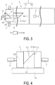
- is a diagram illustrating the step of winding a belt-like member around a forming drum in a plan view.
- FIG. 4
- is a diagram illustrating a cylindrical member in which a belt-like member is formed in a cylindrical shape in a front view of a drum.
- FIG. 5
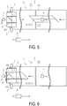
- is a diagram illustrating the status in which another belt-like member to be wound around the outer peripheral surface of the cylindrical member is placed on a transport conveyor belt in a plan view.
- FIG. 6
- is a diagram illustrating the step of winding the other belt-like member in
FIG. 5 around the forming drum in a plan view. - FIG. 7
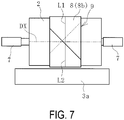
- is a diagram illustrating the status in which another belt-like member is laminated and wound around the outer peripheral surface of the cylindrical member in a front view of the drum.
- A method and device for forming a cylindrical member of the present invention will be described on the basis of the embodiments illustrated in the diagrams as follows.
- A forming
device 1 for forming a cylindrical member of the present invention illustrated inFIGS. 1 and 2 (hereinafter, the forming device 1) forms belt-like members 8 (8a,8b) as acylindrical member 9. Examples of the belt-like member 8 include a belt member used as a reinforcing member for a rubber product such as tires, and various rubber extruded members such as a tread rubber and a side rubber for pneumatic tires. The belt member is a member in which a plurality of steel cords disposed at a predetermined cord angle are covered with a rubber. - The belt-
like members like members like members like members like members like members - The forming
device 1 includes atransport conveyor belt 3 that transports the belt-like member 8 placed thereon, a formingdrum 2 that winds and forms the transported belt-like member 8 into a cylindrical shape, apre-winding position sensor 4 that detects the positions of the member reference lines L1 and L2 drawn on the belt-like member 8, and acontroller 6 to which data detected by thepre-winding position sensor 4 is input. In this embodiment, the formingdevice 1 further includes apost-winding position sensor 5 that detects the position of the member reference lines L1 and L2 drawn on thecylindrical member 9. The detection data by thepost-winding position sensor 5 is also input to thecontroller 6. An example of thepre-winding position sensor 4 and thepost-winding position sensor 5 includes a camera capable of acquiring captured image data. - In this embodiment, two
transport conveyor belts transport conveyor belt 3a arranged at the front side in the transport direction extends to the lower position of the formingdrum 2. The transporting direction of thetransport conveyor belt 3 is orthogonal to the drum axial center DX of the formingdrum 2. - The
pre-winding position sensor 4 is, for example, arranged at a position above thetransport conveyor belts transport conveyor belts post-winding position sensor 5 is arranged with its detection unit facing to the peripheral surface of the formingdrum 2. - The forming
drum 2 has a cylindrical shape and includes amovement mechanism 7 that moves the formingdrum 2 in the drum width direction. A hydraulic cylinder and the like can be used as themovement mechanism 7. Thecontroller 6 controls the movement of themovement mechanism 7. The formingdrum 2 may be fixed in the predetermined position and the transportingconveyor 3a may be moved in the drum width direction by themovement mechanism 7. - The position data of the drum reference line DL is input to the
controller 6 in advance. The drum reference line DL is set in the predetermined position in the drum width direction and is orthogonal to the drum axial center DX of the formingdrum 2. The drum reference line DL is, for example, set in the center position of the drum width direction. The drum reference line DL can be set in any positions in the drum width direction. Thecontroller 6 controls the rotation speed of the formingdrum 2, and the transport speed of thetransport conveyor belt 3. - Next, an example of the steps of forming a cylindrical member of the present invention will be described.
- As illustrated in
FIG. 1 and FIG. 2 , two of thetransport conveyor belts 3 are synchronously moved at the identical transport speed to move the belt-like member 8a from the rear sidetransport conveyor belt 3b to the front sidetransport conveyor belt 3a. During the movement, thepre-winding position sensor 4 detects the position of the member reference line L1 extending in the longitudinal direction of the belt-like member 8a, placed on thetransport conveyor belt 3, along the entire length of the belt-like member 8a in the longitudinal direction thereof. - Next, as illustrated in
FIG. 3 , the transport speed of thetransport conveyor belt 3a and the circumferential speed of the forming drum at the outer peripheral surface are set to the same speed during operation, and, as a result, the belt-like member 8a moved by thetransport conveyor belt 3a is moved and wound so that the belt-like member 8a is transferred on the outer peripheral surface of the formingdrum 2. During the above operation, on the basis of data detected by the pre-winding position sensor 4 (the position data of the member reference line L1) and the position data of the drum reference line DL, thecontroller 6 controls themovement mechanism 7 to move the formingdrum 2 in the drum width direction with respect to thetransport conveyor belt 3a. - As a result of the above described control by the
controller 6, the belt-like member 8a is wound around the formingdrum 2 to form thecylindrical member 9 as illustrated inFIG. 4 while the position of the member reference line L1 and the position of the drum reference line DL are matched in the drum width direction, and the belt-like member 8a is wound around the formingdrum 2. The member reference line L1 is a reference when winding the belt-like member 8a around the formingdrum 2. - The drum reference line DL is a straight line orthogonal to the drum axial center DX of the forming drum. Thus, even if the belt-
like member 8a (the member reference line L1) meanders before winding around the formingdrum 2, the belt-like member 8a can be accurately formed into a cylindrical shape without meandering by winding the belt-like member 8a around formingdrum 2 while the member reference line L1 and the drum reference line DL are matched. With the above method, tires manufactured using the formedcylindrical member 9 excel in terms of uniformity and can have consistent quality. - Next, an example of the steps of forming another belt-
like member 8a in a cylindrical shape by laminating and winding another belt-like member 8b around the outer peripheral surface of the formedcylindrical member 9 will be described. - As illustrated in
FIG. 5 , two of thetransport conveyor belts 3 are synchronically moved at the identical transport speed to move the belt-like member 8b from the rear sidetransport conveyor belt 3b to the front sidetransport conveyor belt 3a. During the movement, thepre-winding position sensor 4 detects the width direction position of the member reference line L2 extending in the longitudinal direction of the belt-like member 8b, placed on thetransport conveyor belt 3, along the entire length of the belt-like member 8b in the longitudinal direction thereof. - Next, as illustrated in
FIG. 6 , the transport speed of thetransport conveyor belt 3a and the circumferential speed of the formingdrum 2 at the outer peripheral surface are set to the same speed for operation, and, as a result, the belt-like member 8b moved to thetransport conveyor belt 3a is moved and wound so that the belt-like member 8b is transferred on the outer peripheral surface of thecylindrical member 9. Further, more preferably, the transport speed of thetransport conveyor belt 3a and the circumferential speed of thecylindrical member 9 at the outer peripheral surface are set to the same speed for operation, and, as a result, the belt-like member 8b moved to thetransport conveyor belt 3a is moved and wound so that the belt-like member 8b is transferred on the outer peripheral surface of thecylindrical member 9. That is, thecontroller 6 calculates the circumferential speed at the outer peripheral surface of the outward positioned surface of thecylindrical member 9 on the basis of a thickness of the belt-like member 8a from the formingdrum 2, and the formingdrum 2 is rotated at the calculated circumferential speed. - When winding the belt-
like member 8b around the outer peripheral surface of thecylindrical member 9, thecontroller 6 controls themovement mechanism 7 to move the formingdrum 2 in the drum width direction with respect to thetransport conveyor belt 3a, on the basis of the data of the belt-like member 8b detected by the pre-winding position sensor 4 (the position data of the member reference line L2) and the member reference line L1 drawn on thecylindrical member 9. - As a result of the above described control by the
controller 6, the belt-like member 8b is wound around the formingdrum 2 to form the belt-like member 8b in a cylindrical shape illustrated inFIG. 7 while the position of the member reference line L2 and the position of the member reference line L1 drawn on thecylindrical member 9 are matched in the drum width direction, and the belt-like member 8b is wound around the formingdrum 2. The member reference line L2 is a reference when winding the belt-like member 8b around the formingdrum 2. - Since, in some cases, the
cylindrical member 9 may be wound with slight meandering to the formingdrum 2, another belt-like member 8b may meander when the belt-like member 8b is wound around thecylindrical member 9 using the formingdrum 2 as a reference. Also, a malfunction may possibly happen in which another belt-like member 8b is wound being offset in the width direction from the predetermined position set in advance with respect to the belt-like member 8a. However, in this embodiment, since the position data of the member reference line L1 drawn on thecylindrical member 9 is used as a reference when winding another belt-like member 8b, the embodiment enables another belt-like member 8b that is subsequently laminated to be formed accurately in a cylindrical shape without meandering with respect to thecylindrical member 9 and shifting (offsetting) each belt-like member in the width direction. - The position of the member reference line L1 drawn on the
cylindrical member 9 is acquired on the basis of data detected by thepost-winding position sensor 5 detecting the position of the member reference line L1 drawn on thecylindrical member 9. In this case, because the position of the member reference line L1 drawn on thecylindrical member 9, which winds around the formingdrum 2, is directly detected, the position of the member reference line L1 drawn on thecylindrical member 9 can be acquired with even higher precision. - Other methods of acquiring the position of the member reference line L1 drawn on the
cylindrical member 9 may be applied. For instance, when winding the belt-like member 8a around the formingdrum 2, thecontroller 6 stores the position data of the member reference line L1 drawn on the belt-like member 8a. That is, thecontroller 6 stores the position (in the drum width direction and circumferential direction position) of the member reference line L1 with respect to the formingdrum 2 upon winding the belt-like member 8a around the formingdrum 2 as the position of the member reference line L1 drawn on thecylindrical member 9. Then, the position of the member reference line L1 drawn on thecylindrical member 9 is acquired on the basis of the stored position data of the member reference line L1. In this case, thepost-winding position sensor 5 is unnecessary. - The above described steps of forming the belt-
like member 8b in a cylindrical shape can be applied when yet another belt-like member is laminated and wound around the outer peripheral surface of the belt-like member 8b to form the belt-like member in a cylindrical shape. For instance, the present invention can be applied to the pneumatic tires manufacturing step when forming belt member in a cylindrical shape. - That is, at first, a first layer belt-like belt member (the belt-
like member 8a) is wound around the formingdrum 2 to form thecylindrical member 9, and a second layer belt-like belt member (the belt-like member 8b) is wound around the outer peripheral surface of thecylindrical member 9 to form it in a cylindrical shape, and, in the next, a belt-like tread rubber is wound around the outer peripheral surface of thecylindrical member 9 formed by forming the second layer belt-like belt member in a cylindrical shape to form it in a cylindrical shape. -
- 1 Forming device
- 2 Forming drum
- 3 (3a, 3b) Transport conveyor belt
- 4 Pre-winding position sensor
- 5 Post-winding position sensor
- 6 Controller
- 7 Movement mechanism
- 8 (8a, 8b) Belt-like member
- 9 Cylindrical member
- DL Drum reference line
- DX Drum axial center
- L1, L2 Member reference line
Claims (8)
- A method of forming a cylindrical member by transporting a belt-like member placed on a transport conveyor belt to a forming drum and winding the belt-like member around the forming drum to form the belt-like member in a cylindrical shape, the method comprising the steps of:detecting a position of a member reference line by a pre-winding position sensor before winding the belt-like member around the forming drum, the member reference line extending in a longitudinal direction of the belt-like member along the entire length of the belt-like member in the longitudinal direction thereof; andforming the belt-like member in a cylindrical shape by winding the belt-like member around the forming drum while the forming drum is relatively moved in a drum width direction with respect to the transport conveyor belt by a controller and the member reference line and a drum reference line are matched, on the basis of data detected by the pre-winding position sensor and position data of the drum reference line orthogonal to a drum axial center of the forming drum and set in a predetermined position in the drum width direction.
- The method of forming a cylindrical member according to claim 1, wherein, when another belt-like member is laminated and wound around an outer peripheral surface of the cylindrical member to form the other belt-like member in a cylindrical shape, the pre-winding position sensor detects a position of a member reference line before winding the other belt-like member around the outer peripheral surface of the cylindrical member, the member reference line extending in a longitudinal direction of the other belt-like member along the entire length of the other belt-like member in the longitudinal direction thereof; and the other belt-like member is wound while the forming drum is relatively moved in the drum width direction with respect to the transport conveyor belt by the controller and the member reference line drawn on the other belt-like member and the member reference line drawn on the cylindrical member are matched, on the basis of detection data of the other belt-like member by the pre-winding position sensor and position data of the member reference line drawn on the cylindrical member.
- The method of forming a cylindrical member according to claim 2, wherein a post-winding position sensor detects the position of the member reference line drawn on the cylindrical member, and the position of the member reference line drawn on the cylindrical member is acquired on the basis of the detection data.
- The method of forming the cylindrical member according to claim 2, wherein the controller stores the position data of the member reference line on the belt-like member upon winding the belt-like member around the forming drum, and the position of the member reference line drawn on the cylindrical member is acquired on the basis of the stored position data.
- A forming device for forming a cylindrical member including a transport conveyor belt that transports a belt-like member placed thereon and a forming drum that winds the belt-like member that is transported to form the belt-like member in a cylindrical shape, the forming device comprising:a pre-winding position sensor that detects a position of a member reference line extending in a longitudinal direction of the belt-like member, placed on the transport conveyor belt, along the entire length of the belt-like member in the longitudinal direction thereof; anda controller to which data detected by the pre-winding position sensor is input,wherein the belt-like member is formed in a cylindrical shape by winding the belt-like member around the forming drum while the forming drum is relatively moved in a drum width direction with respect to the transport conveyor belt by the controller and the member reference line and a drum reference line are matched, on the basis of detection data by the pre-winding position sensor and position data of the drum reference line orthogonal to a drum axial center of the forming drum and set in a predetermined position of the drum width direction, the position data of the drum reference line being previously input to the controller.
- The device for forming a cylindrical member according to claim 5, wherein, when another belt-like member is laminated and wound around an outer peripheral surface of the cylindrical member formed by being wound around the forming drum to form the other belt-like member in a cylindrical shape, the pre-winding position sensor detects a position of a member reference line extending in a longitudinal direction of the other belt-like member, placed on the transport conveyor belt, along the entire length of the other belt-like member in the longitudinal direction thereof, and the other belt-like member is wound while the forming drum is relatively moved in the drum width direction with respect to the transport conveyor belt by the controller and the member reference line drawn on the other belt-like member and the member reference line drawn on the cylindrical member are matched, on the basis of data of the other belt-like member detected by the pre-winding position sensor and position data of the member reference line drawn on the cylindrical member.
- The method of forming a cylindrical member according to claim 6, wherein the method is provided with a post-winding position sensor that detects the position of the member reference line drawn on the cylindrical member, and is configured to acquire the position of the member reference line drawn on the cylindrical member on the basis of the data detected by the post-winding position sensor.
- The device for forming a cylindrical member according to claim 6, wherein, upon winding the belt-like member around the forming drum, the controller stores the position data of the member reference line on the belt-like member, and the position of the member reference line drawn on the cylindrical member is acquired on the basis of the stored position data.
Applications Claiming Priority (2)
| Application Number | Priority Date | Filing Date | Title |
|---|---|---|---|
| JP2014097995A JP5817884B1 (en) | 2014-05-09 | 2014-05-09 | Method and apparatus for forming cylindrical member |
| PCT/JP2015/063333 WO2015170748A1 (en) | 2014-05-09 | 2015-05-08 | Cylindrical-member molding method and device |
Publications (3)
| Publication Number | Publication Date |
|---|---|
| EP3141382A1 true EP3141382A1 (en) | 2017-03-15 |
| EP3141382A4 EP3141382A4 (en) | 2018-03-28 |
| EP3141382B1 EP3141382B1 (en) | 2019-07-03 |
Family
ID=54392596
Family Applications (1)
| Application Number | Title | Priority Date | Filing Date |
|---|---|---|---|
| EP15789267.0A Active EP3141382B1 (en) | 2014-05-09 | 2015-05-08 | Cylindrical-member molding method and device |
Country Status (6)
| Country | Link |
|---|---|
| US (1) | US10183454B2 (en) |
| EP (1) | EP3141382B1 (en) |
| JP (1) | JP5817884B1 (en) |
| KR (1) | KR101749557B1 (en) |
| CN (1) | CN106255588B (en) |
| WO (1) | WO2015170748A1 (en) |
Cited By (2)
| Publication number | Priority date | Publication date | Assignee | Title |
|---|---|---|---|---|
| EP4286145A1 (en) * | 2022-06-02 | 2023-12-06 | Continental Reifen Deutschland GmbH | Method for producing a vehicle tyre |
| EP4360863A1 (en) * | 2022-10-31 | 2024-05-01 | The Goodyear Tire & Rubber Company | Tire building apparatus and method |
Families Citing this family (4)
| Publication number | Priority date | Publication date | Assignee | Title |
|---|---|---|---|---|
| JP6264415B1 (en) | 2016-09-16 | 2018-01-24 | 横浜ゴム株式会社 | Apparatus and method for manufacturing cylindrical member |
| NL2022874B1 (en) * | 2019-04-05 | 2020-10-08 | Vmi Holland Bv | Calibration tool and method |
| JP6881507B2 (en) * | 2019-06-17 | 2021-06-02 | 横浜ゴム株式会社 | Manufacturing equipment and methods for unvulcanized annular rubber members |
| JP6881508B2 (en) * | 2019-06-17 | 2021-06-02 | 横浜ゴム株式会社 | Manufacturing equipment and method for unvulcanized strip-shaped rubber members |
Family Cites Families (12)
| Publication number | Priority date | Publication date | Assignee | Title |
|---|---|---|---|---|
| NL8803156A (en) * | 1988-12-23 | 1990-07-16 | Vmi Epe Holland | CENTERING DEVICE. |
| JPH05229032A (en) * | 1992-02-19 | 1993-09-07 | Toyo Tire & Rubber Co Ltd | Method for centering rubber sheet |
| JP3762820B2 (en) * | 1997-09-22 | 2006-04-05 | 横浜ゴム株式会社 | Winding method for belt-shaped material |
| JP2001113610A (en) * | 1999-10-15 | 2001-04-24 | Bridgestone Corp | Method for centering belt member with cushion and device therefor |
| JP3982330B2 (en) * | 2002-06-06 | 2007-09-26 | Jfeスチール株式会社 | Winding the metal strip |
| ATE355963T1 (en) * | 2003-02-13 | 2007-03-15 | Michelin Soc Tech | SHAPING AND PLACING A TIRE BELT PIECE ON A HOLDING DEVICE |
| DE102006017882B4 (en) | 2006-04-13 | 2010-08-05 | Texmag Gmbh Vertriebsgesellschaft | Device and method for building a tire |
| JP4893675B2 (en) | 2008-03-24 | 2012-03-07 | 横浜ゴム株式会社 | Belt member manufacturing apparatus and method |
| JP5129838B2 (en) | 2010-04-21 | 2013-01-30 | 住友ゴム工業株式会社 | Winding device for belt-shaped member for tire |
| SI2582512T1 (en) * | 2010-06-18 | 2015-09-30 | Harburg-Freudenberger Maschinenbau Gmbh | Method and device for producing green tires |
| JP5746578B2 (en) | 2011-07-05 | 2015-07-08 | 東洋ゴム工業株式会社 | Method and apparatus for inspecting winding state of sheet-like member |
| JP6132487B2 (en) | 2012-07-27 | 2017-05-24 | 株式会社島精機製作所 | Sheet material meander prevention device |
-
2014
- 2014-05-09 JP JP2014097995A patent/JP5817884B1/en active Active
-
2015
- 2015-05-08 EP EP15789267.0A patent/EP3141382B1/en active Active
- 2015-05-08 CN CN201580022208.6A patent/CN106255588B/en active Active
- 2015-05-08 US US15/310,090 patent/US10183454B2/en active Active
- 2015-05-08 WO PCT/JP2015/063333 patent/WO2015170748A1/en not_active Ceased
- 2015-05-08 KR KR1020167032227A patent/KR101749557B1/en active Active
Cited By (3)
| Publication number | Priority date | Publication date | Assignee | Title |
|---|---|---|---|---|
| EP4286145A1 (en) * | 2022-06-02 | 2023-12-06 | Continental Reifen Deutschland GmbH | Method for producing a vehicle tyre |
| EP4360863A1 (en) * | 2022-10-31 | 2024-05-01 | The Goodyear Tire & Rubber Company | Tire building apparatus and method |
| EP4653810A3 (en) * | 2022-10-31 | 2026-01-07 | The Goodyear Tire & Rubber Company | Tire building machine |
Also Published As
| Publication number | Publication date |
|---|---|
| CN106255588A (en) | 2016-12-21 |
| WO2015170748A1 (en) | 2015-11-12 |
| JP2015214078A (en) | 2015-12-03 |
| KR20160137652A (en) | 2016-11-30 |
| US20170274607A1 (en) | 2017-09-28 |
| CN106255588B (en) | 2021-12-17 |
| EP3141382A4 (en) | 2018-03-28 |
| JP5817884B1 (en) | 2015-11-18 |
| US10183454B2 (en) | 2019-01-22 |
| KR101749557B1 (en) | 2017-06-21 |
| EP3141382B1 (en) | 2019-07-03 |
Similar Documents
| Publication | Publication Date | Title |
|---|---|---|
| EP3141382B1 (en) | Cylindrical-member molding method and device | |
| EP3162537B1 (en) | Device and method for inspecting cylindrical member | |
| CN110099860B (en) | Conveyor belt monitoring system | |
| US20230150219A1 (en) | Method and apparatus for controlling the feed of semifinished products in a tyre building process | |
| US20210354412A1 (en) | Belt and tread drum | |
| WO2017072072A8 (en) | Arrangement and method for processing a web of packaging material, and a packaging material | |
| EP3052310B1 (en) | Method for picking up and placing tire components on a transfer drum | |
| JP6838288B2 (en) | Band-shaped member joining method and equipment | |
| KR20200133805A (en) | Supply device and method of rubber sheet member | |
| JP7214942B2 (en) | Tire component manufacturing apparatus and tire component manufacturing method | |
| CN111216388B (en) | Tire member molding device, tire member inspection method, and tire member manufacturing method | |
| JP2006056074A (en) | Method and apparatus for placing strip-like member | |
| JP5941387B2 (en) | Tire manufacturing system | |
| US20220227084A1 (en) | Method and device for producing a rubber component | |
| JP6324819B2 (en) | Apparatus and method for forming annular member | |
| JP5276947B2 (en) | Raw tire manufacturing equipment | |
| JP7331516B2 (en) | Method for manufacturing pneumatic tires | |
| JP7225788B2 (en) | Method of winding belt-shaped rubber sheet | |
| JP2016168814A (en) | Rubber strip winding device | |
| JP2009113892A (en) | Connecting method of sheet-like member | |
| WO2013157441A1 (en) | Rubber strip sticking and leakage detection device | |
| EP2070852A2 (en) | Cylinder for guiding and centering ribbon-like material and control device associated thereto |
Legal Events
| Date | Code | Title | Description |
|---|---|---|---|
| STAA | Information on the status of an ep patent application or granted ep patent |
Free format text: STATUS: THE INTERNATIONAL PUBLICATION HAS BEEN MADE |
|
| PUAI | Public reference made under article 153(3) epc to a published international application that has entered the european phase |
Free format text: ORIGINAL CODE: 0009012 |
|
| STAA | Information on the status of an ep patent application or granted ep patent |
Free format text: STATUS: REQUEST FOR EXAMINATION WAS MADE |
|
| 17P | Request for examination filed |
Effective date: 20161207 |
|
| AK | Designated contracting states |
Kind code of ref document: A1 Designated state(s): AL AT BE BG CH CY CZ DE DK EE ES FI FR GB GR HR HU IE IS IT LI LT LU LV MC MK MT NL NO PL PT RO RS SE SI SK SM TR |
|
| AX | Request for extension of the european patent |
Extension state: BA ME |
|
| RIN1 | Information on inventor provided before grant (corrected) |
Inventor name: MATSUMURA, KENSUKE |
|
| DAV | Request for validation of the european patent (deleted) | ||
| DAX | Request for extension of the european patent (deleted) | ||
| A4 | Supplementary search report drawn up and despatched |
Effective date: 20180223 |
|
| RIC1 | Information provided on ipc code assigned before grant |
Ipc: B29D 30/30 20060101AFI20180219BHEP |
|
| GRAP | Despatch of communication of intention to grant a patent |
Free format text: ORIGINAL CODE: EPIDOSNIGR1 |
|
| STAA | Information on the status of an ep patent application or granted ep patent |
Free format text: STATUS: GRANT OF PATENT IS INTENDED |
|
| INTG | Intention to grant announced |
Effective date: 20190117 |
|
| GRAS | Grant fee paid |
Free format text: ORIGINAL CODE: EPIDOSNIGR3 |
|
| GRAA | (expected) grant |
Free format text: ORIGINAL CODE: 0009210 |
|
| STAA | Information on the status of an ep patent application or granted ep patent |
Free format text: STATUS: THE PATENT HAS BEEN GRANTED |
|
| AK | Designated contracting states |
Kind code of ref document: B1 Designated state(s): AL AT BE BG CH CY CZ DE DK EE ES FI FR GB GR HR HU IE IS IT LI LT LU LV MC MK MT NL NO PL PT RO RS SE SI SK SM TR |
|
| REG | Reference to a national code |
Ref country code: GB Ref legal event code: FG4D |
|
| REG | Reference to a national code |
Ref country code: CH Ref legal event code: EP Ref country code: AT Ref legal event code: REF Ref document number: 1150458 Country of ref document: AT Kind code of ref document: T Effective date: 20190715 |
|
| REG | Reference to a national code |
Ref country code: IE Ref legal event code: FG4D |
|
| REG | Reference to a national code |
Ref country code: DE Ref legal event code: R096 Ref document number: 602015033189 Country of ref document: DE |
|
| REG | Reference to a national code |
Ref country code: NL Ref legal event code: FP |
|
| REG | Reference to a national code |
Ref country code: LT Ref legal event code: MG4D |
|
| REG | Reference to a national code |
Ref country code: AT Ref legal event code: MK05 Ref document number: 1150458 Country of ref document: AT Kind code of ref document: T Effective date: 20190703 |
|
| PG25 | Lapsed in a contracting state [announced via postgrant information from national office to epo] |
Ref country code: PT Free format text: LAPSE BECAUSE OF FAILURE TO SUBMIT A TRANSLATION OF THE DESCRIPTION OR TO PAY THE FEE WITHIN THE PRESCRIBED TIME-LIMIT Effective date: 20191104 Ref country code: SE Free format text: LAPSE BECAUSE OF FAILURE TO SUBMIT A TRANSLATION OF THE DESCRIPTION OR TO PAY THE FEE WITHIN THE PRESCRIBED TIME-LIMIT Effective date: 20190703 Ref country code: BG Free format text: LAPSE BECAUSE OF FAILURE TO SUBMIT A TRANSLATION OF THE DESCRIPTION OR TO PAY THE FEE WITHIN THE PRESCRIBED TIME-LIMIT Effective date: 20191003 Ref country code: HR Free format text: LAPSE BECAUSE OF FAILURE TO SUBMIT A TRANSLATION OF THE DESCRIPTION OR TO PAY THE FEE WITHIN THE PRESCRIBED TIME-LIMIT Effective date: 20190703 Ref country code: LT Free format text: LAPSE BECAUSE OF FAILURE TO SUBMIT A TRANSLATION OF THE DESCRIPTION OR TO PAY THE FEE WITHIN THE PRESCRIBED TIME-LIMIT Effective date: 20190703 Ref country code: FI Free format text: LAPSE BECAUSE OF FAILURE TO SUBMIT A TRANSLATION OF THE DESCRIPTION OR TO PAY THE FEE WITHIN THE PRESCRIBED TIME-LIMIT Effective date: 20190703 Ref country code: CZ Free format text: LAPSE BECAUSE OF FAILURE TO SUBMIT A TRANSLATION OF THE DESCRIPTION OR TO PAY THE FEE WITHIN THE PRESCRIBED TIME-LIMIT Effective date: 20190703 Ref country code: AT Free format text: LAPSE BECAUSE OF FAILURE TO SUBMIT A TRANSLATION OF THE DESCRIPTION OR TO PAY THE FEE WITHIN THE PRESCRIBED TIME-LIMIT Effective date: 20190703 Ref country code: NO Free format text: LAPSE BECAUSE OF FAILURE TO SUBMIT A TRANSLATION OF THE DESCRIPTION OR TO PAY THE FEE WITHIN THE PRESCRIBED TIME-LIMIT Effective date: 20191003 |
|
| PG25 | Lapsed in a contracting state [announced via postgrant information from national office to epo] |
Ref country code: GR Free format text: LAPSE BECAUSE OF FAILURE TO SUBMIT A TRANSLATION OF THE DESCRIPTION OR TO PAY THE FEE WITHIN THE PRESCRIBED TIME-LIMIT Effective date: 20191004 Ref country code: ES Free format text: LAPSE BECAUSE OF FAILURE TO SUBMIT A TRANSLATION OF THE DESCRIPTION OR TO PAY THE FEE WITHIN THE PRESCRIBED TIME-LIMIT Effective date: 20190703 Ref country code: LV Free format text: LAPSE BECAUSE OF FAILURE TO SUBMIT A TRANSLATION OF THE DESCRIPTION OR TO PAY THE FEE WITHIN THE PRESCRIBED TIME-LIMIT Effective date: 20190703 Ref country code: IS Free format text: LAPSE BECAUSE OF FAILURE TO SUBMIT A TRANSLATION OF THE DESCRIPTION OR TO PAY THE FEE WITHIN THE PRESCRIBED TIME-LIMIT Effective date: 20191103 Ref country code: RS Free format text: LAPSE BECAUSE OF FAILURE TO SUBMIT A TRANSLATION OF THE DESCRIPTION OR TO PAY THE FEE WITHIN THE PRESCRIBED TIME-LIMIT Effective date: 20190703 Ref country code: AL Free format text: LAPSE BECAUSE OF FAILURE TO SUBMIT A TRANSLATION OF THE DESCRIPTION OR TO PAY THE FEE WITHIN THE PRESCRIBED TIME-LIMIT Effective date: 20190703 |
|
| PG25 | Lapsed in a contracting state [announced via postgrant information from national office to epo] |
Ref country code: TR Free format text: LAPSE BECAUSE OF FAILURE TO SUBMIT A TRANSLATION OF THE DESCRIPTION OR TO PAY THE FEE WITHIN THE PRESCRIBED TIME-LIMIT Effective date: 20190703 |
|
| PG25 | Lapsed in a contracting state [announced via postgrant information from national office to epo] |
Ref country code: EE Free format text: LAPSE BECAUSE OF FAILURE TO SUBMIT A TRANSLATION OF THE DESCRIPTION OR TO PAY THE FEE WITHIN THE PRESCRIBED TIME-LIMIT Effective date: 20190703 Ref country code: PL Free format text: LAPSE BECAUSE OF FAILURE TO SUBMIT A TRANSLATION OF THE DESCRIPTION OR TO PAY THE FEE WITHIN THE PRESCRIBED TIME-LIMIT Effective date: 20190703 Ref country code: DK Free format text: LAPSE BECAUSE OF FAILURE TO SUBMIT A TRANSLATION OF THE DESCRIPTION OR TO PAY THE FEE WITHIN THE PRESCRIBED TIME-LIMIT Effective date: 20190703 Ref country code: RO Free format text: LAPSE BECAUSE OF FAILURE TO SUBMIT A TRANSLATION OF THE DESCRIPTION OR TO PAY THE FEE WITHIN THE PRESCRIBED TIME-LIMIT Effective date: 20190703 Ref country code: IT Free format text: LAPSE BECAUSE OF FAILURE TO SUBMIT A TRANSLATION OF THE DESCRIPTION OR TO PAY THE FEE WITHIN THE PRESCRIBED TIME-LIMIT Effective date: 20190703 |
|
| PG25 | Lapsed in a contracting state [announced via postgrant information from national office to epo] |
Ref country code: SK Free format text: LAPSE BECAUSE OF FAILURE TO SUBMIT A TRANSLATION OF THE DESCRIPTION OR TO PAY THE FEE WITHIN THE PRESCRIBED TIME-LIMIT Effective date: 20190703 Ref country code: IS Free format text: LAPSE BECAUSE OF FAILURE TO SUBMIT A TRANSLATION OF THE DESCRIPTION OR TO PAY THE FEE WITHIN THE PRESCRIBED TIME-LIMIT Effective date: 20200224 Ref country code: SM Free format text: LAPSE BECAUSE OF FAILURE TO SUBMIT A TRANSLATION OF THE DESCRIPTION OR TO PAY THE FEE WITHIN THE PRESCRIBED TIME-LIMIT Effective date: 20190703 |
|
| REG | Reference to a national code |
Ref country code: DE Ref legal event code: R097 Ref document number: 602015033189 Country of ref document: DE |
|
| PLBE | No opposition filed within time limit |
Free format text: ORIGINAL CODE: 0009261 |
|
| STAA | Information on the status of an ep patent application or granted ep patent |
Free format text: STATUS: NO OPPOSITION FILED WITHIN TIME LIMIT |
|
| PG2D | Information on lapse in contracting state deleted |
Ref country code: IS |
|
| 26N | No opposition filed |
Effective date: 20200603 |
|
| PG25 | Lapsed in a contracting state [announced via postgrant information from national office to epo] |
Ref country code: SI Free format text: LAPSE BECAUSE OF FAILURE TO SUBMIT A TRANSLATION OF THE DESCRIPTION OR TO PAY THE FEE WITHIN THE PRESCRIBED TIME-LIMIT Effective date: 20190703 |
|
| PG25 | Lapsed in a contracting state [announced via postgrant information from national office to epo] |
Ref country code: CH Free format text: LAPSE BECAUSE OF NON-PAYMENT OF DUE FEES Effective date: 20200531 Ref country code: LI Free format text: LAPSE BECAUSE OF NON-PAYMENT OF DUE FEES Effective date: 20200531 Ref country code: MC Free format text: LAPSE BECAUSE OF FAILURE TO SUBMIT A TRANSLATION OF THE DESCRIPTION OR TO PAY THE FEE WITHIN THE PRESCRIBED TIME-LIMIT Effective date: 20190703 |
|
| REG | Reference to a national code |
Ref country code: BE Ref legal event code: MM Effective date: 20200531 |
|
| GBPC | Gb: european patent ceased through non-payment of renewal fee |
Effective date: 20200508 |
|
| PG25 | Lapsed in a contracting state [announced via postgrant information from national office to epo] |
Ref country code: LU Free format text: LAPSE BECAUSE OF NON-PAYMENT OF DUE FEES Effective date: 20200508 |
|
| PG25 | Lapsed in a contracting state [announced via postgrant information from national office to epo] |
Ref country code: IE Free format text: LAPSE BECAUSE OF NON-PAYMENT OF DUE FEES Effective date: 20200508 Ref country code: GB Free format text: LAPSE BECAUSE OF NON-PAYMENT OF DUE FEES Effective date: 20200508 |
|
| PG25 | Lapsed in a contracting state [announced via postgrant information from national office to epo] |
Ref country code: BE Free format text: LAPSE BECAUSE OF NON-PAYMENT OF DUE FEES Effective date: 20200531 |
|
| PG25 | Lapsed in a contracting state [announced via postgrant information from national office to epo] |
Ref country code: MT Free format text: LAPSE BECAUSE OF FAILURE TO SUBMIT A TRANSLATION OF THE DESCRIPTION OR TO PAY THE FEE WITHIN THE PRESCRIBED TIME-LIMIT Effective date: 20190703 Ref country code: CY Free format text: LAPSE BECAUSE OF FAILURE TO SUBMIT A TRANSLATION OF THE DESCRIPTION OR TO PAY THE FEE WITHIN THE PRESCRIBED TIME-LIMIT Effective date: 20190703 |
|
| PG25 | Lapsed in a contracting state [announced via postgrant information from national office to epo] |
Ref country code: MK Free format text: LAPSE BECAUSE OF FAILURE TO SUBMIT A TRANSLATION OF THE DESCRIPTION OR TO PAY THE FEE WITHIN THE PRESCRIBED TIME-LIMIT Effective date: 20190703 |
|
| REG | Reference to a national code |
Ref country code: FR Ref legal event code: PLFP Year of fee payment: 9 |
|
| P01 | Opt-out of the competence of the unified patent court (upc) registered |
Effective date: 20230512 |
|
| PGFP | Annual fee paid to national office [announced via postgrant information from national office to epo] |
Ref country code: NL Payment date: 20250409 Year of fee payment: 11 |
|
| PGFP | Annual fee paid to national office [announced via postgrant information from national office to epo] |
Ref country code: DE Payment date: 20250402 Year of fee payment: 11 |
|
| PGFP | Annual fee paid to national office [announced via postgrant information from national office to epo] |
Ref country code: FR Payment date: 20250401 Year of fee payment: 11 |