EP3141367A1 - Mold cleaning system - Google Patents
Mold cleaning system Download PDFInfo
- Publication number
- EP3141367A1 EP3141367A1 EP15789593.9A EP15789593A EP3141367A1 EP 3141367 A1 EP3141367 A1 EP 3141367A1 EP 15789593 A EP15789593 A EP 15789593A EP 3141367 A1 EP3141367 A1 EP 3141367A1
- Authority
- EP
- European Patent Office
- Prior art keywords
- mold
- molding surface
- laser
- cleaning system
- laser head
- Prior art date
- Legal status (The legal status is an assumption and is not a legal conclusion. Google has not performed a legal analysis and makes no representation as to the accuracy of the status listed.)
- Granted
Links
Images



Classifications
-
- B—PERFORMING OPERATIONS; TRANSPORTING
- B29—WORKING OF PLASTICS; WORKING OF SUBSTANCES IN A PLASTIC STATE IN GENERAL
- B29D—PRODUCING PARTICULAR ARTICLES FROM PLASTICS OR FROM SUBSTANCES IN A PLASTIC STATE
- B29D30/00—Producing pneumatic or solid tyres or parts thereof
- B29D30/06—Pneumatic tyres or parts thereof (e.g. produced by casting, moulding, compression moulding, injection moulding, centrifugal casting)
- B29D30/0601—Vulcanising tyres; Vulcanising presses for tyres
- B29D30/0662—Accessories, details or auxiliary operations
-
- B—PERFORMING OPERATIONS; TRANSPORTING
- B08—CLEANING
- B08B—CLEANING IN GENERAL; PREVENTION OF FOULING IN GENERAL
- B08B7/00—Cleaning by methods not provided for in a single other subclass or a single group in this subclass
- B08B7/0035—Cleaning by methods not provided for in a single other subclass or a single group in this subclass by radiant energy, e.g. UV, laser, light beam or the like
- B08B7/0042—Cleaning by methods not provided for in a single other subclass or a single group in this subclass by radiant energy, e.g. UV, laser, light beam or the like by laser
-
- B—PERFORMING OPERATIONS; TRANSPORTING
- B23—MACHINE TOOLS; METAL-WORKING NOT OTHERWISE PROVIDED FOR
- B23K—SOLDERING OR UNSOLDERING; WELDING; CLADDING OR PLATING BY SOLDERING OR WELDING; CUTTING BY APPLYING HEAT LOCALLY, e.g. FLAME CUTTING; WORKING BY LASER BEAM
- B23K26/00—Working by laser beam, e.g. welding, cutting or boring
- B23K26/0006—Working by laser beam, e.g. welding, cutting or boring taking account of the properties of the material involved
-
- B—PERFORMING OPERATIONS; TRANSPORTING
- B23—MACHINE TOOLS; METAL-WORKING NOT OTHERWISE PROVIDED FOR
- B23K—SOLDERING OR UNSOLDERING; WELDING; CLADDING OR PLATING BY SOLDERING OR WELDING; CUTTING BY APPLYING HEAT LOCALLY, e.g. FLAME CUTTING; WORKING BY LASER BEAM
- B23K26/00—Working by laser beam, e.g. welding, cutting or boring
- B23K26/02—Positioning or observing the workpiece, e.g. with respect to the point of impact; Aligning, aiming or focusing the laser beam
- B23K26/03—Observing, e.g. monitoring, the workpiece
- B23K26/032—Observing, e.g. monitoring, the workpiece using optical means
-
- B—PERFORMING OPERATIONS; TRANSPORTING
- B23—MACHINE TOOLS; METAL-WORKING NOT OTHERWISE PROVIDED FOR
- B23K—SOLDERING OR UNSOLDERING; WELDING; CLADDING OR PLATING BY SOLDERING OR WELDING; CUTTING BY APPLYING HEAT LOCALLY, e.g. FLAME CUTTING; WORKING BY LASER BEAM
- B23K26/00—Working by laser beam, e.g. welding, cutting or boring
- B23K26/352—Working by laser beam, e.g. welding, cutting or boring for surface treatment
-
- B—PERFORMING OPERATIONS; TRANSPORTING
- B23—MACHINE TOOLS; METAL-WORKING NOT OTHERWISE PROVIDED FOR
- B23K—SOLDERING OR UNSOLDERING; WELDING; CLADDING OR PLATING BY SOLDERING OR WELDING; CUTTING BY APPLYING HEAT LOCALLY, e.g. FLAME CUTTING; WORKING BY LASER BEAM
- B23K26/00—Working by laser beam, e.g. welding, cutting or boring
- B23K26/36—Removing material
-
- B—PERFORMING OPERATIONS; TRANSPORTING
- B29—WORKING OF PLASTICS; WORKING OF SUBSTANCES IN A PLASTIC STATE IN GENERAL
- B29C—SHAPING OR JOINING OF PLASTICS; SHAPING OF MATERIAL IN A PLASTIC STATE, NOT OTHERWISE PROVIDED FOR; AFTER-TREATMENT OF THE SHAPED PRODUCTS, e.g. REPAIRING
- B29C33/00—Moulds or cores; Details thereof or accessories therefor
- B29C33/70—Maintenance
- B29C33/72—Cleaning
-
- B—PERFORMING OPERATIONS; TRANSPORTING
- B29—WORKING OF PLASTICS; WORKING OF SUBSTANCES IN A PLASTIC STATE IN GENERAL
- B29D—PRODUCING PARTICULAR ARTICLES FROM PLASTICS OR FROM SUBSTANCES IN A PLASTIC STATE
- B29D30/00—Producing pneumatic or solid tyres or parts thereof
- B29D30/06—Pneumatic tyres or parts thereof (e.g. produced by casting, moulding, compression moulding, injection moulding, centrifugal casting)
- B29D30/0601—Vulcanising tyres; Vulcanising presses for tyres
- B29D30/0662—Accessories, details or auxiliary operations
- B29D2030/0663—Mould maintenance, e.g. cleaning, washing, repairing
-
- B—PERFORMING OPERATIONS; TRANSPORTING
- B29—WORKING OF PLASTICS; WORKING OF SUBSTANCES IN A PLASTIC STATE IN GENERAL
- B29L—INDEXING SCHEME ASSOCIATED WITH SUBCLASS B29C, RELATING TO PARTICULAR ARTICLES
- B29L2030/00—Pneumatic or solid tyres or parts thereof
Definitions
- the present invention relates to a mold cleaning system; and particularly relates to a mold cleaning system which makes it possible to prevent scratches on a molding surface while efficiently removing dirt therefrom without requiring a hand operation by a person, even for molds having complicated molding-surface shapes.
- Dirt derived from rubber components or compounding agents is adhered slightly to a molding surface of a mold for vulcanizing rubber products such as tires every time the vulcanization is performed. Since the dirt gradually accumulates as the mold is used repeatedly, leaving the dirt as it is negatively impacts the quality of the products to be vulcanized. Thus, as appropriate, the dirt needs to be removed by cleaning the molding surface. Examples of known mold cleaning methods include a shot blasting cleaning method, a laser beam cleaning method, and a plasma cleaning method.
- the molding surface is easy to be scratched.
- an area that the plasma cleaning method can clean in a unit time is small. Therefore, the laser beam cleaning method is more desirable considering efficiency.
- Patent Documents 1 and 2 Various mold cleaning methods using laser beam have been proposed (for example, see Patent Documents 1 and 2).
- the dirt is removed by irradiating, from a laser head, the molding surface of the mold with a laser beam (CO 2 laser beam) supplied from a laser oscillator.
- a laser beam CO 2 laser beam
- an arm that moves the laser head is controlled by the original shape data (CAD data etc.) of the mold and a position correction means for the laser head and the arm moves the laser head along concaves and convexes on the molding surface (see paragraphs [0011] and [0021] to [0025] etc. of Patent Document 1).
- the molding surface of the mold is not always formed in the same shape but is formed in various shapes.
- an operation for invoking the original shape data of the mold stored in a control device is required every time the mold cleaning is performed.
- a checking if the mold to be cleaned and the original shape data therefor correspond to each other is required every time the cleaning is performed and thereby the operation becomes complicated.
- a laser irradiator is fixed to a predetermined position, and a mold is rotated to move the mold so that the mold surface changes from a vertical posture into a slanting posture with respect to the optical axis of the laser beam.
- a process such as teaching this motion in advance is required to rotate the mold in this way.
- An object of the present invention is to provide a mold cleaning system which makes it possible to prevent scratches on a molding surface while efficiently removing dirt therefrom without requiring a hand operation by a person, even for molds having complicated molding-surface shapes.
- a mold cleaning system of the present invention is provided with a laser oscillator, a laser head configured to irradiate a molding surface of a mold with a laser beam from the laser oscillator, an arm configured to move the laser head freely in three dimensions, a control device configured to control the motion of the arm, a database in which an identification mark assigned to each mold to be cleaned to identify the mold, and shape data for the molding surface of the mold to which the identification mark is assigned are stored in advance in association with each other; and a mark detector configured to detect the identification mark.
- the shape data for the molding surface of the mold stored in the database is obtained on the basis of the identification mark assigned to the mold and detected by the mark detector when the mold is cleaned.
- the identification mark assigned to the mold to be cleaned is detected by the mark detector when the mold is cleaned, and the shape data for the molding surface of the mold stored in the database is automatically obtained on the basis of the detected identification mark.
- the laser head is moved along the molding surface on the basis of the shape data obtained from the database while irradiating with the laser beam to clean the molding surface, it is possible to prevent scratches on the molding surface while efficiently removing the dirt therefrom without requiring a hand operation by a person, even for molds having complicated molding-surface shapes.
- the mold cleaning system can also be provided with a camera configured to obtain image data for the molding surface.
- the mold cleaning system can also be configured to grasp a cleaning state of the molding surface on the basis of the image data obtained by the camera, store the grasped cleaning state and position information of the molding surface in the control device, and, for the positions on the molding surface in which the grasped cleaning state does not satisfy a preset standard, perform cleaning again by irradiating with the laser beam from the laser head.
- the mold cleaning system can also be provided with a plurality of laser heads having different laser irradiation widths as the laser head.
- the mold cleaning system can also be configured to perform cleaning for particular preset portions by using a laser head having a relatively small laser irradiation width or by using a laser head having a relatively large laser irradiation width with the laser head having a relatively small laser irradiation width. With this configuration, the cleaning can be finished in a short time by using the laser head having a relatively large laser irradiation width for relatively flat and wide portions.
- the portions having complicated shapes can be evenly irradiated with the laser beam by using the laser head having a relatively small laser irradiation width, and as a result, the dirt can be removed cleanly.
- the mold cleaning system can also be provided with a temperature sensor configured to successively detect a temperature of the molding surface that is irradiated with the laser beam.
- the mold cleaning system can also be configured to suspend an irradiation with the laser beam when the temperature detected by the temperature sensor exceeds a preset acceptable temperature.
- the present invention can also be used to clean molds for vulcanizing other rubber products than tires.
- a mold cleaning system 1 of the present invention illustrated in FIG. 1 is provided with a laser oscillator 2, a laser head 4, an arm 6 to which the laser head 4 is attached, a control device 7 that controls the motion of the arm 6, a database 8, and a mark detector 3a.
- the mold cleaning system 1 is further provided with a camera 3b that obtains image data for a molding surface 12 of a mold 11, and a temperature sensor 3c that successively detects a temperature of the molding surface 12 that is irradiated with a laser beam L.
- the detection data detected by the mark detector 3a, the image data obtained by the camera 3b, and the temperature data detected by the temperature sensor 3c are input to the control device 7.
- the main components of the cleaning system 1 except for the laser oscillator 2 are disposed in a cleaning booth 9, which becomes a closed space.
- the cleaning booth 9 is provided with an inlet door 9a and an outlet door 9b and has a structure that becomes a closed space and can shield the laser beam L when the inlet door 9a and the outlet door 9b are closed.
- the inlet door 9a is connected with a carrying-in conveyor apparatus 10a and the outlet door 9b is connected with a carrying-out conveyor apparatus 10c.
- the space between the carrying-in conveyor apparatus 10a and the carrying-out conveyor apparatus 10c becomes an internal space of the cleaning booth 9 and a processing conveyor apparatus 10b is disposed at this position.
- the processing conveyor apparatus 10b is bent and extended to be an arc shape.
- the mold 11 to be cleaned is placed on the carrying-in conveyor apparatus 10a and the cleaned mold 11 is placed on the carrying-out conveyor apparatus 10c.
- the processing conveyor apparatus 10b functions as a processing table when the mold 11 is cleaned.
- the laser oscillator 2 and the laser head 4 are connected by an optical fiber cable 2a.
- the laser beam L supplied by the laser oscillator 2 is transmitted to the laser head 4 through the optical fiber cable 2a.
- the molding surface 12 of the mold 11 is irradiated with the laser beam L by the laser head 4.
- the arm 6 is rotatably attached to an arm base 5 and is configured by rotatably connecting a plurality of arm parts 6a, 6b.
- the laser head 4 is removably attached to the tip of the arm 6. Therefore, the laser head 4 can be moved freely in three dimensions by controlling the motion of the arm 6.
- a plurality of laser heads 4a, 4b having different laser irradiation widths are provided as illustrated in FIG. 4 .
- One is the laser head 4a having a relatively large laser irradiation width and the other is the laser head 4b having a relatively small laser irradiation width.
- the laser head 4a has a configuration in which a galvano mirror is incorporated and the laser beam L can be scanned in a width direction and a wider range can be irradiated with the laser beam L.
- the laser irradiation width is variable (for example, from 4 to 70 mm).
- the other laser head 4b irradiates a pinpoint with the laser beam L.
- a plurality of the laser heads 4a having variable laser irradiation widths may be provided to use a different laser irradiation width for each laser head.
- the oscillating frequency of the laser oscillator 2 is from 10 to 40 kHz.
- the frequency in which the laser beam L is scanned from the laser head 4a in the width direction is, for example, from 20 to 150 Hz.
- a database 8 is disposed in a storage unit of the control device 7.
- Each of the molds 11 to be cleaned is assigned an identification mark D to identify the mold 11.
- the identification mark D is assigned to the mold 11 by engraving or by attaching a label or the like.
- the identification mark D is configured with, for example, numbers, characters, or a combination thereof.
- shape data for the molding surface 12 of each mold 11 is stored.
- Each shape data is stored in the database 11 with the identification mark D assigned to the mold 11 having the molding surface 12 based on that shape data. That is, in the database 8, the shape data for the molding surface 12 of the mold 11 to which the identification mark D is assigned and the identification mark D are stored in advance in association with each other.
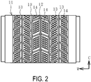
- the mold 11 to be cleaned is not only a normal type mold but also, for example, a studless-tire vulcanization mold illustrated in FIG. 2 .
- Groove forming projections 13 and sipe forming projections 14 are projected on the molding surface 12 of the mold 11.
- the groove forming projections 13 are casted integrally with the base material of the mold 11 and the sipe forming projections 14 are separately attached to the molding surface 12.
- the base material of the mold 11 is usually made of aluminum and the sipe forming projections 14 are made of steel or the like.
- the thickness of the sipe forming projections 14 is about from 0.4 to 1.2 mm.
- the groove forming projections 13 may be thin depending on a tread pattern of a tire, for example, in the case of a complicated tread pattern.
- the sipe forming projections 14 or thin groove forming projections 13 are the parts that are easy to be scratched when the mold is cleaned.
- a C arrow, an R arrow, and a W arrow described in FIG. 2 , FIG. 4 , and FIG. 5 respectively indicate a circumferential direction, a radius direction, and a width direction of a tire that is to be inserted into the mold 11 and vulcanized therein.
- FIG. 3 Another example of the type of mold 11 to be cleaned is a cast splicing mold for pneumatic tire vulcanization illustrated in FIG. 3 .
- the mold 11 is produced by so-called cast splicing in which a first casting part 15 is casted and a second casting part 16 is casted thereafter.
- a small gap g is defined in a cast splicing part M between the first casting part 15 and the second casting part 16.
- the size of the small gap g is, for example, from 5 to 80 ⁇ m.
- An exhaust hole 17 in communication with the small gap g is defined.
- the mold 11 to be cleaned is placed on the carrying-in conveyor apparatus 10a.
- the inlet door 9a is opened, and the carrying-in conveyor apparatus 10a and the processing conveyor apparatus 10b are operated to move the mold 11 to be cleaned onto the processing conveyor apparatus 10b and position the mold 11 at a predetermined position.
- the inlet door 9a is closed so that the cleaning booth 9 becomes a closed space.
- an interlocking structure in which the laser oscillator 2 is not actuated until the cleaning booth 9 becomes a closed space.
- the identification mark D assigned to the mold 11 is detected by the mark detector 3a.
- the shape data for the molding surface 12 of the mold 11 stored in the database 8 is automatically obtained.
- the motion of the arm 6 is controlled on the basis of the obtained shape data for the molding surface 12 of the mold 11 to move the laser head 4 along the molding surface 12 as illustrated in FIG. 4 and FIG. 5 .
- the molding surface 12 is irradiated with the laser beam L supplied from the laser oscillator 2.
- the dirt X adhered to the molding surface 12 is removed and cleaned by the emitted laser beam L.
- the movement direction of the laser head 4 and the irradiation direction of the laser beam L are controlled while keeping the spacing between the tip of the laser head 4 and the opposing molding surface 12 as constant as possible.
- the movement velocity of the laser head 4 is kept as constant as possible, and the laser head 4 is moved to cover the range to be cleaned.
- the molding surface 12 is irradiated with the laser beam L by moving the laser head 4a having a relatively large laser irradiation width to cover the range to be cleaned, and then, the molding surface 12 is irradiated with the laser beam L by using the laser head 4b having a relatively small laser irradiation width.
- the shape data for the molding surface 12 of the mold 11 stored in the database 8 is automatically obtained on the basis of the identification mark D detected by the mark detector 3a when the mold 11 is cleaned.
- the laser head 4 is moved along the molding surface 12 on the basis of the shape data obtained from the database 8 while irradiated with the laser beam, it is possible to prevent scratches on the molding surface 12 while efficiently removing the dirt X therefrom without requiring a hand operation by a person, even for molds 11 having the molding surfaces 12 with complicated shapes, such as studless-tire vulcanization molds or cast splicing molds for pneumatic tire vulcanization.
- the image data for the cleaned molding surface 12 is obtained by the camera 3b, and the cleaning state of the molding surface 12 is grasped on the basis of the obtained image data.
- the grasped cleaning state and the position information of the molding surface are stored in the control device 7. After irradiating the entire range of the molding surface 12 with the laser beam L, for the positions of the molding surface 12 in which the grasped cleaning state does not satisfy a preset standard, the cleaning is performed again by moving the laser head 4 to the positions and irradiating with the laser beam L. It is also possible to provide a configuration in which the mark detector 3a has the function of the camera 3b and concurrently serves as both devices.
- a standard for determining whether the cleaning state is appropriate (dirt X has been removed) or inappropriate (dirt X is remaining) is input and set to the control device 7 in advance. By using the control device 7, whether the grasped cleaning state satisfies the preset standard is determined.
- the standard for determining the cleaning state is set on the basis of, for example, a color density of the image data for the molding surface 12 obtained by the camera 3b. If the density is greater than a certain degree, the cleaning state indicating that the dirt X is remaining is set. Alternatively, it is possible to obtain the image data for the molding surface 12 immediately before and immediately after the laser beam L is emitted, compare these image data, and set the standard on the basis of the change in the color density. If the color density has not changed or the degree of the change is small, the cleaning state indicating that the dirt X is remaining is set. With this configuration, only the positions (range) that are particularly dirty are re-cleaned later, which is advantageous for removing the dirt X efficiently and cleanly.
- the control device 7 It is also possible to input and set particular portions to the control device 7 in advance, and for the preset particular portions, perform cleaning by using the laser head 4b having a relatively small laser irradiation width or by using the laser head 4a having a relatively large laser irradiation width with the laser head 4b having a relatively small laser irradiation width.
- the particular portions include a range having a complicated shape such as a range around the bottom of the sipe forming projections 14 illustrated in FIG. 2 , or the inner circumferential surface of the small gap g in the cast splicing part M illustrated in FIG. 3 .
- the cleaning can be finished in a short time for relatively flat and wide portions by using the laser head 4a having a relatively large laser irradiation width.
- the portions having complicated shapes can be irradiated evenly with the laser beam L by using the laser head 4b having a relatively small laser irradiation width, and as a result, the dirt X can be removed cleanly.
- the temperature of the molding surface 12 that is irradiated with the laser beam L can be successively detected by the temperature sensor 3c.
- An acceptable temperature is input and set to the control device 7 in advance.
- the acceptable temperature is set to a predetermined temperature that does not reach the melting temperature of the mold 11.
- the irradiation with the laser beam L is suspended when the temperature detected by the temperature sensor 3c exceeds the preset acceptable temperature.
- the outlet door 9b is opened and the processing conveyor belt 10b and the carrying-out conveyor belt 10c are operated to move the cleaned mold 11 out of the cleaning booth 9.
- the inlet door 9a is opened and the carrying-in conveyor belt 10a is operated to move the next mold 11 to be cleaned from the outside to the inside of the cleaning booth 9 and position the mold 11 at a predetermined position on the processing conveyor 10b. In this way, the mold 11 is cleaned sequentially and continuously.
Landscapes
- Engineering & Computer Science (AREA)
- Mechanical Engineering (AREA)
- Physics & Mathematics (AREA)
- Optics & Photonics (AREA)
- Plasma & Fusion (AREA)
- Moulds For Moulding Plastics Or The Like (AREA)
Abstract
Description
- The present invention relates to a mold cleaning system; and particularly relates to a mold cleaning system which makes it possible to prevent scratches on a molding surface while efficiently removing dirt therefrom without requiring a hand operation by a person, even for molds having complicated molding-surface shapes.
- Dirt derived from rubber components or compounding agents is adhered slightly to a molding surface of a mold for vulcanizing rubber products such as tires every time the vulcanization is performed. Since the dirt gradually accumulates as the mold is used repeatedly, leaving the dirt as it is negatively impacts the quality of the products to be vulcanized. Thus, as appropriate, the dirt needs to be removed by cleaning the molding surface. Examples of known mold cleaning methods include a shot blasting cleaning method, a laser beam cleaning method, and a plasma cleaning method.
- With the shot blasting cleaning method, the molding surface is easy to be scratched. Thus, to prevent scratches on the molding surface caused by the cleaning, it is desirable to use the laser beam cleaning method in which the molding surface is irradiated with a laser beam and the dirt is removed by the shock wave caused by the irradiation, or to use the plasma cleaning method in which the dirt is removed with the chemical reaction of the dirt caused by a generated plasma. However, an area that the plasma cleaning method can clean in a unit time is small. Therefore, the laser beam cleaning method is more desirable considering efficiency.
- Various mold cleaning methods using laser beam have been proposed (for example, see
Patent Documents 1 and 2). In the cleaning method disclosed inPatent Document 1, the dirt is removed by irradiating, from a laser head, the molding surface of the mold with a laser beam (CO2 laser beam) supplied from a laser oscillator. At this time, an arm (manipulator) that moves the laser head is controlled by the original shape data (CAD data etc.) of the mold and a position correction means for the laser head and the arm moves the laser head along concaves and convexes on the molding surface (see paragraphs [0011] and [0021] to [0025] etc. of Patent Document 1). - However, the molding surface of the mold is not always formed in the same shape but is formed in various shapes. Thus, in the method disclosed in
Patent Document 1, to clean molds having different molding-surface shapes, an operation for invoking the original shape data of the mold stored in a control device is required every time the mold cleaning is performed. In the case of tire vulcanization molds for which there are numerous types of molding-surface shapes, there is a problem that a checking if the mold to be cleaned and the original shape data therefor correspond to each other is required every time the cleaning is performed and thereby the operation becomes complicated. - In the cleaning method disclosed in
Patent Document 2, a laser irradiator is fixed to a predetermined position, and a mold is rotated to move the mold so that the mold surface changes from a vertical posture into a slanting posture with respect to the optical axis of the laser beam. A process such as teaching this motion in advance is required to rotate the mold in this way. -
- Patent Document 1: Japanese Unexamined Patent Application Publication No.
2008-62633A - Patent Document 2: Japanese Unexamined Patent Application Publication No.
2004-167744A - An object of the present invention is to provide a mold cleaning system which makes it possible to prevent scratches on a molding surface while efficiently removing dirt therefrom without requiring a hand operation by a person, even for molds having complicated molding-surface shapes.
- To achieve the above object, a mold cleaning system of the present invention is provided with a laser oscillator, a laser head configured to irradiate a molding surface of a mold with a laser beam from the laser oscillator, an arm configured to move the laser head freely in three dimensions, a control device configured to control the motion of the arm, a database in which an identification mark assigned to each mold to be cleaned to identify the mold, and shape data for the molding surface of the mold to which the identification mark is assigned are stored in advance in association with each other; and a mark detector configured to detect the identification mark. The shape data for the molding surface of the mold stored in the database is obtained on the basis of the identification mark assigned to the mold and detected by the mark detector when the mold is cleaned. By controlling the motion of the arm on the basis of the obtained shape data, the laser head is moved along the molding surface while irradiating with the laser beam to clean the molding surface.
- According to the present invention, the identification mark assigned to the mold to be cleaned is detected by the mark detector when the mold is cleaned, and the shape data for the molding surface of the mold stored in the database is automatically obtained on the basis of the detected identification mark. Thus, it is no longer required to perform manual operations for invoking the shape data for the molding surface of the mold to be cleaned and to check the correspondence relation between the actual mold and the shape data every time the cleaning is performed. Also, since the laser head is moved along the molding surface on the basis of the shape data obtained from the database while irradiating with the laser beam to clean the molding surface, it is possible to prevent scratches on the molding surface while efficiently removing the dirt therefrom without requiring a hand operation by a person, even for molds having complicated molding-surface shapes.
- For example, the mold cleaning system can also be provided with a camera configured to obtain image data for the molding surface. The mold cleaning system can also be configured to grasp a cleaning state of the molding surface on the basis of the image data obtained by the camera, store the grasped cleaning state and position information of the molding surface in the control device, and, for the positions on the molding surface in which the grasped cleaning state does not satisfy a preset standard, perform cleaning again by irradiating with the laser beam from the laser head. With this configuration, only the positions (range) that are particularly dirty are re-cleaned later, which is advantageous for removing the dirt efficiently and cleanly.
- The mold cleaning system can also be provided with a plurality of laser heads having different laser irradiation widths as the laser head. The mold cleaning system can also be configured to perform cleaning for particular preset portions by using a laser head having a relatively small laser irradiation width or by using a laser head having a relatively large laser irradiation width with the laser head having a relatively small laser irradiation width. With this configuration, the cleaning can be finished in a short time by using the laser head having a relatively large laser irradiation width for relatively flat and wide portions. Meanwhile, for portions in which concaves and convexes exist complicatedly in a narrow range on the molding surface, the portions having complicated shapes can be evenly irradiated with the laser beam by using the laser head having a relatively small laser irradiation width, and as a result, the dirt can be removed cleanly.
- The mold cleaning system can also be provided with a temperature sensor configured to successively detect a temperature of the molding surface that is irradiated with the laser beam. The mold cleaning system can also be configured to suspend an irradiation with the laser beam when the temperature detected by the temperature sensor exceeds a preset acceptable temperature. With this configuration, the molding surface can be avoided from being overheated by the irradiated laser beam. As such, a defect that the molding surface is thermally deformed by the laser beam can be prevented.
- Although studless-tire vulcanization molds have complicated molding-surface shapes and cast splicing molds for pneumatic tire vulcanization have small gaps defined on the molding surfaces thereof, by applying the present invention, scratches in the molding surfaces can be prevented while efficiently removing the dirt therefrom.
-
-
FIG. 1 is an explanatory drawing illustrating a mold cleaning system of the present invention as viewed in a plan view. -
FIG. 2 is an explanatory drawing illustrating a molding surface of a studless-tire vulcanization mold as viewed in a plan view. -
FIG. 3 is an explanatory drawing illustrating a molding surface of a cast splicing mold as viewed in an enlarged cross-section. -
FIG. 4 is an explanatory drawing illustrating a laser head and a mold to be cleaned as viewed in a side view. -
FIG. 5 is an explanatory drawing illustrating a laser head and a mold to be cleaned as viewed in a front view. - A mold cleaning system of the present invention will now be described on the basis of the embodiments illustrated in the drawings.
- Although a tire vulcanization mold is to be cleaned in the following description, the present invention can also be used to clean molds for vulcanizing other rubber products than tires.
- A
mold cleaning system 1 of the present invention illustrated inFIG. 1 is provided with alaser oscillator 2, alaser head 4, anarm 6 to which thelaser head 4 is attached, acontrol device 7 that controls the motion of thearm 6, a database 8, and a mark detector 3a. In this embodiment, themold cleaning system 1 is further provided with acamera 3b that obtains image data for amolding surface 12 of amold 11, and atemperature sensor 3c that successively detects a temperature of themolding surface 12 that is irradiated with a laser beam L. The detection data detected by the mark detector 3a, the image data obtained by thecamera 3b, and the temperature data detected by thetemperature sensor 3c are input to thecontrol device 7. - The main components of the
cleaning system 1 except for thelaser oscillator 2 are disposed in a cleaning booth 9, which becomes a closed space. The cleaning booth 9 is provided with aninlet door 9a and anoutlet door 9b and has a structure that becomes a closed space and can shield the laser beam L when theinlet door 9a and theoutlet door 9b are closed. - The
inlet door 9a is connected with a carrying-inconveyor apparatus 10a and theoutlet door 9b is connected with a carrying-outconveyor apparatus 10c. The space between the carrying-inconveyor apparatus 10a and the carrying-outconveyor apparatus 10c becomes an internal space of the cleaning booth 9 and aprocessing conveyor apparatus 10b is disposed at this position. In this embodiment, theprocessing conveyor apparatus 10b is bent and extended to be an arc shape. Themold 11 to be cleaned is placed on the carrying-inconveyor apparatus 10a and the cleanedmold 11 is placed on the carrying-outconveyor apparatus 10c. Theprocessing conveyor apparatus 10b functions as a processing table when themold 11 is cleaned. - The
laser oscillator 2 and thelaser head 4 are connected by anoptical fiber cable 2a. The laser beam L supplied by thelaser oscillator 2 is transmitted to thelaser head 4 through theoptical fiber cable 2a. In the present invention, it is preferable to use a YAG laser beam as the laser beam L. - The
molding surface 12 of themold 11 is irradiated with the laser beam L by thelaser head 4. Thearm 6 is rotatably attached to anarm base 5 and is configured by rotatably connecting a plurality ofarm parts laser head 4 is removably attached to the tip of thearm 6. Therefore, thelaser head 4 can be moved freely in three dimensions by controlling the motion of thearm 6. - In this embodiment, a plurality of
laser heads FIG. 4 . One is thelaser head 4a having a relatively large laser irradiation width and the other is thelaser head 4b having a relatively small laser irradiation width. Thelaser head 4a has a configuration in which a galvano mirror is incorporated and the laser beam L can be scanned in a width direction and a wider range can be irradiated with the laser beam L. The laser irradiation width is variable (for example, from 4 to 70 mm). Theother laser head 4b irradiates a pinpoint with the laser beam L. A plurality of the laser heads 4a having variable laser irradiation widths may be provided to use a different laser irradiation width for each laser head. For example, the oscillating frequency of thelaser oscillator 2 is from 10 to 40 kHz. The frequency in which the laser beam L is scanned from thelaser head 4a in the width direction is, for example, from 20 to 150 Hz. - A database 8 is disposed in a storage unit of the
control device 7. Each of themolds 11 to be cleaned is assigned an identification mark D to identify themold 11. The identification mark D is assigned to themold 11 by engraving or by attaching a label or the like. The identification mark D is configured with, for example, numbers, characters, or a combination thereof. - In the database 8, shape data for the
molding surface 12 of eachmold 11 is stored. Each shape data is stored in thedatabase 11 with the identification mark D assigned to themold 11 having themolding surface 12 based on that shape data. That is, in the database 8, the shape data for themolding surface 12 of themold 11 to which the identification mark D is assigned and the identification mark D are stored in advance in association with each other. - The
mold 11 to be cleaned is not only a normal type mold but also, for example, a studless-tire vulcanization mold illustrated inFIG. 2 . Groove formingprojections 13 andsipe forming projections 14 are projected on themolding surface 12 of themold 11. Thegroove forming projections 13 are casted integrally with the base material of themold 11 and thesipe forming projections 14 are separately attached to themolding surface 12. The base material of themold 11 is usually made of aluminum and thesipe forming projections 14 are made of steel or the like. - The thickness of the
sipe forming projections 14 is about from 0.4 to 1.2 mm. Thegroove forming projections 13 may be thin depending on a tread pattern of a tire, for example, in the case of a complicated tread pattern. Thus, thesipe forming projections 14 or thingroove forming projections 13 are the parts that are easy to be scratched when the mold is cleaned. It is noted that a C arrow, an R arrow, and a W arrow described inFIG. 2 ,FIG. 4 , andFIG. 5 respectively indicate a circumferential direction, a radius direction, and a width direction of a tire that is to be inserted into themold 11 and vulcanized therein. - Another example of the type of
mold 11 to be cleaned is a cast splicing mold for pneumatic tire vulcanization illustrated inFIG. 3 . Themold 11 is produced by so-called cast splicing in which afirst casting part 15 is casted and asecond casting part 16 is casted thereafter. By the solidification and shrinkage of a casted melting metal, a small gap g is defined in a cast splicing part M between thefirst casting part 15 and thesecond casting part 16. The size of the small gap g is, for example, from 5 to 80 µm. Anexhaust hole 17 in communication with the small gap g is defined. In themold 11, unnecessary air or gas when the tire is vulcanized is discharged from themolding surface 12 to theexhaust hole 17 through the small gap g, and then discharged out of themold 11 through theexhaust hole 17. The small gap g is a part that is easy to be scratched when the mold is cleaned. - A procedure for cleaning the
molding surface 12 of themold 11 by using thecleaning system 1 will now be described. - First, the
mold 11 to be cleaned is placed on the carrying-inconveyor apparatus 10a. Next, theinlet door 9a is opened, and the carrying-inconveyor apparatus 10a and theprocessing conveyor apparatus 10b are operated to move themold 11 to be cleaned onto theprocessing conveyor apparatus 10b and position themold 11 at a predetermined position. Then, theinlet door 9a is closed so that the cleaning booth 9 becomes a closed space. Provided here is an interlocking structure in which thelaser oscillator 2 is not actuated until the cleaning booth 9 becomes a closed space. - Next, the identification mark D assigned to the
mold 11 is detected by the mark detector 3a. On the basis of the detected identification mark D, the shape data for themolding surface 12 of themold 11 stored in the database 8 is automatically obtained. - Next, the motion of the
arm 6 is controlled on the basis of the obtained shape data for themolding surface 12 of themold 11 to move thelaser head 4 along themolding surface 12 as illustrated inFIG. 4 andFIG. 5 . While thelaser head 4 is being moved in this way, themolding surface 12 is irradiated with the laser beam L supplied from thelaser oscillator 2. The dirt X adhered to themolding surface 12 is removed and cleaned by the emitted laser beam L. - To restrict irradiation unevenness of the laser beam L, the movement direction of the
laser head 4 and the irradiation direction of the laser beam L are controlled while keeping the spacing between the tip of thelaser head 4 and the opposingmolding surface 12 as constant as possible. The movement velocity of thelaser head 4 is kept as constant as possible, and thelaser head 4 is moved to cover the range to be cleaned. - In this embodiment, although two
laser heads other laser head 4 thereafter. For example, themolding surface 12 is irradiated with the laser beam L by moving thelaser head 4a having a relatively large laser irradiation width to cover the range to be cleaned, and then, themolding surface 12 is irradiated with the laser beam L by using thelaser head 4b having a relatively small laser irradiation width. - As described above, according to the present invention, the shape data for the
molding surface 12 of themold 11 stored in the database 8 is automatically obtained on the basis of the identification mark D detected by the mark detector 3a when themold 11 is cleaned. Thus, even whenmany molds 11 havingdifferent molding surfaces 12 are to be cleaned, it is no longer required to perform manual operations for invoking the shape data for themolding surface 12 of themold 11 to be cleaned and checking the correspondence relation between the actual mold and the shape data every time the cleaning is performed. - And, since the
laser head 4 is moved along themolding surface 12 on the basis of the shape data obtained from the database 8 while irradiated with the laser beam, it is possible to prevent scratches on themolding surface 12 while efficiently removing the dirt X therefrom without requiring a hand operation by a person, even formolds 11 having the molding surfaces 12 with complicated shapes, such as studless-tire vulcanization molds or cast splicing molds for pneumatic tire vulcanization. - In this embodiment, the image data for the cleaned
molding surface 12 is obtained by thecamera 3b, and the cleaning state of themolding surface 12 is grasped on the basis of the obtained image data. The grasped cleaning state and the position information of the molding surface are stored in thecontrol device 7. After irradiating the entire range of themolding surface 12 with the laser beam L, for the positions of themolding surface 12 in which the grasped cleaning state does not satisfy a preset standard, the cleaning is performed again by moving thelaser head 4 to the positions and irradiating with the laser beam L. It is also possible to provide a configuration in which the mark detector 3a has the function of thecamera 3b and concurrently serves as both devices. - A standard for determining whether the cleaning state is appropriate (dirt X has been removed) or inappropriate (dirt X is remaining) is input and set to the
control device 7 in advance. By using thecontrol device 7, whether the grasped cleaning state satisfies the preset standard is determined. - The standard for determining the cleaning state is set on the basis of, for example, a color density of the image data for the
molding surface 12 obtained by thecamera 3b. If the density is greater than a certain degree, the cleaning state indicating that the dirt X is remaining is set. Alternatively, it is possible to obtain the image data for themolding surface 12 immediately before and immediately after the laser beam L is emitted, compare these image data, and set the standard on the basis of the change in the color density. If the color density has not changed or the degree of the change is small, the cleaning state indicating that the dirt X is remaining is set. With this configuration, only the positions (range) that are particularly dirty are re-cleaned later, which is advantageous for removing the dirt X efficiently and cleanly. - It is also possible to input and set particular portions to the
control device 7 in advance, and for the preset particular portions, perform cleaning by using thelaser head 4b having a relatively small laser irradiation width or by using thelaser head 4a having a relatively large laser irradiation width with thelaser head 4b having a relatively small laser irradiation width. Examples of the particular portions include a range having a complicated shape such as a range around the bottom of thesipe forming projections 14 illustrated inFIG. 2 , or the inner circumferential surface of the small gap g in the cast splicing part M illustrated inFIG. 3 . - With this configuration, the cleaning can be finished in a short time for relatively flat and wide portions by using the
laser head 4a having a relatively large laser irradiation width. Meanwhile, for portions in which concaves and convexes exist complicatedly in a narrow range on themolding surface 12, the portions having complicated shapes, can be irradiated evenly with the laser beam L by using thelaser head 4b having a relatively small laser irradiation width, and as a result, the dirt X can be removed cleanly. - The temperature of the
molding surface 12 that is irradiated with the laser beam L can be successively detected by thetemperature sensor 3c. An acceptable temperature is input and set to thecontrol device 7 in advance. The acceptable temperature is set to a predetermined temperature that does not reach the melting temperature of themold 11. The irradiation with the laser beam L is suspended when the temperature detected by thetemperature sensor 3c exceeds the preset acceptable temperature. With this configuration, even if malfunctions such as the reduction of the movement velocity or the stopping of thelaser head 4 occur due to unintentional factors, themolding surface 12 can be avoided from being overheated by the emitted laser beam L. As such, a malfunction that themolding surface 12 is thermally deformed or scratched by the laser beam L can be prevented. - After the cleaning of the
mold 11 is finished, theoutlet door 9b is opened and theprocessing conveyor belt 10b and the carrying-outconveyor belt 10c are operated to move the cleanedmold 11 out of the cleaning booth 9. At this time, theinlet door 9a is opened and the carrying-inconveyor belt 10a is operated to move thenext mold 11 to be cleaned from the outside to the inside of the cleaning booth 9 and position themold 11 at a predetermined position on theprocessing conveyor 10b. In this way, themold 11 is cleaned sequentially and continuously. -
- 1 Cleaning system
- 2 Laser oscillator
- 2a Optical fiber cable
- 3a Mark detector
- 3b Camera
- 3c Temperature sensor
- 4, 4a, 4b Laser head
- 5 Arm base
- 6 Arm
- 6a, 6b Arm part
- 7 Control device
- 8 Database
- 9 Cleaning booth
- 9a Inlet door
- 9b Outlet door
- 10a Carrying-in conveyor apparatus
- 10b Processing conveyor apparatus (processing table)
- 10c Carrying-out conveyor apparatus
- 11 Mold
- 12 Molding surface
- 13 Groove forming projection
- 14 Sipe forming projection
- 15 First casting part
- 16 Second casting part
- 17 Exhaust hole
- D Identification mark
- M Cast splicing part
- L Laser beam
- X Dirt
- g Small gap
Claims (5)
- A mold cleaning system comprising:a laser oscillator;a laser head configured to irradiate a molding surface of a mold with a laser beam supplied from the laser oscillator;an arm configured to move the laser head freely in three dimensions; a control device configured to control motion of the arm;a database in which an identification mark assigned to each mold to be cleaned to identify the mold, and shape data for the molding surface of the mold to which the identification mark is assigned are stored in advance in association with each other; anda mark detector configured to detect the identification mark; wherein the shape data for the molding surface of the mold stored in the database is obtained on the basis of the identification mark assigned to the mold and detected by the mark detector when the mold is cleaned, and wherein, by controlling the motion of the arm on the basis of the obtained shape data, the laser head is moved along the molding surface while irradiating with the laser beam to clean the molding surface.
- The mold cleaning system according to claim 1, further comprisinga camera configured to obtain image data for the molding surface, wherein the mold cleaning system is configured to grasp a cleaning state of the molding surface on the basis of the image data obtained by the camera, store the grasped cleaning state and position information of the molding surface in the control device, and, for positions on the molding surface in which the grasped cleaning state does not satisfy a preset standard, perform cleaning again by irradiating with the laser beam from the laser head.
- The mold cleaning system according to claim 1 or 2, further comprisinga plurality of laser heads having different laser irradiation widths as the laser head, wherein the mold cleaning system is configured to perform cleaning for particular preset portions by using a laser head having a relatively small laser irradiation width or by using a laser head having a relatively large laser irradiation width with the laser head having a relatively small laser irradiation width.
- The mold cleaning system according to any one of claims 1 to 3, further comprisinga temperature sensor configured to successively detect a temperature of the molding surface that is irradiated with the laser beam, wherein the mold cleaning system is configured to suspend an irradiation with the laser beam when the temperature detected by the temperature sensor exceeds a preset acceptable temperature.
- The mold cleaning system according to any one of claims 1 to 4, wherein the mold is a studless-tire vulcanization mold or a cast splicing mold for pneumatic tire vulcanization.
Applications Claiming Priority (2)
| Application Number | Priority Date | Filing Date | Title |
|---|---|---|---|
| JP2014097993A JP5835400B2 (en) | 2014-05-09 | 2014-05-09 | Mold cleaning system |
| PCT/JP2015/063335 WO2015170750A1 (en) | 2014-05-09 | 2015-05-08 | Mold cleaning system |
Publications (3)
| Publication Number | Publication Date |
|---|---|
| EP3141367A1 true EP3141367A1 (en) | 2017-03-15 |
| EP3141367A4 EP3141367A4 (en) | 2018-01-10 |
| EP3141367B1 EP3141367B1 (en) | 2020-01-08 |
Family
ID=54392598
Family Applications (1)
| Application Number | Title | Priority Date | Filing Date |
|---|---|---|---|
| EP15789593.9A Active EP3141367B1 (en) | 2014-05-09 | 2015-05-08 | Mold cleaning system |
Country Status (5)
| Country | Link |
|---|---|
| US (1) | US11072139B2 (en) |
| EP (1) | EP3141367B1 (en) |
| JP (1) | JP5835400B2 (en) |
| CN (2) | CN106457620A (en) |
| WO (1) | WO2015170750A1 (en) |
Cited By (3)
| Publication number | Priority date | Publication date | Assignee | Title |
|---|---|---|---|---|
| EP3162524A4 (en) * | 2014-06-26 | 2018-02-21 | The Yokohama Rubber Co., Ltd. | Mold cleaning system |
| DE102017206815A1 (en) * | 2017-04-24 | 2018-10-25 | Volkswagen Aktiengesellschaft | Process for cleaning a generatively manufactured part |
| EP3814029A4 (en) * | 2018-05-08 | 2022-01-26 | Automation Innovation Pty Ltd | LASER CLEANING SYSTEM |
Families Citing this family (16)
| Publication number | Priority date | Publication date | Assignee | Title |
|---|---|---|---|---|
| EP2609647B1 (en) | 2010-08-24 | 2017-03-15 | Sion Power Corporation | Electrolyte materials for use in electrochemical cells |
| US9577289B2 (en) | 2012-12-17 | 2017-02-21 | Sion Power Corporation | Lithium-ion electrochemical cell, components thereof, and methods of making and using same |
| JP6583010B2 (en) * | 2016-01-19 | 2019-10-02 | 住友ゴム工業株式会社 | Bent hole cleaning device and vent hole cleaning method. |
| KR101735373B1 (en) | 2016-03-11 | 2017-05-16 | 주식회사 제펠 | Laser cleaning apparatus for removing scrap of upper mold |
| CN107309221B (en) * | 2017-08-09 | 2019-12-24 | 温州大学激光与光电智能制造研究院 | Hand-held type self-adaptation laser belt cleaning device of compound beam plastic of dual wavelength |
| US10744539B2 (en) * | 2017-10-27 | 2020-08-18 | The Boeing Company | Optimized-coverage selective laser ablation systems and methods |
| US11801620B2 (en) | 2017-12-28 | 2023-10-31 | Keymical Holding Inc. | Automatic plant for cleaning molds for tires |
| JP6590010B2 (en) * | 2018-02-09 | 2019-10-16 | 横浜ゴム株式会社 | Vulcanizing mold cleaning apparatus and method |
| JP7238555B2 (en) * | 2019-04-03 | 2023-03-14 | 住友ゴム工業株式会社 | Laser cleaning method for mold surface |
| JP7117264B2 (en) * | 2019-04-16 | 2022-08-12 | 株式会社ブリヂストン | Vent hole cleaning device and vent hole cleaning method |
| CN111420938B (en) * | 2020-04-28 | 2022-03-15 | 株洲国创轨道科技有限公司 | Intelligent laser cleaning method and device for multiple laser heads |
| US11748942B2 (en) | 2020-08-13 | 2023-09-05 | Siemens Mobility Pty Ltd | System and method for automatically generating trajectories for laser applications |
| JP7614486B2 (en) * | 2020-09-14 | 2025-01-16 | 横浜ゴム株式会社 | How to clean tire curing bladders |
| CN113351580B (en) * | 2021-07-06 | 2024-03-29 | 联亚智能科技(苏州)有限公司 | Method for detecting laser cleaning quality of inner surface of tire through identification mark |
| MX2025014372A (en) * | 2023-05-30 | 2026-02-03 | Iso Inovasyon Ve Arge Anonim Sirketi | A ROBOTIC SYSTEM FOR CLEANING TIRE MOLDS INTEGRATED INTO A LASER AND ULTRASONIC BATH |
| CN117141021B (en) * | 2023-10-31 | 2024-01-26 | 山东产研强远激光科技有限公司 | Laser cleaning device and method for tire mold pattern blocks and side plates |
Family Cites Families (14)
| Publication number | Priority date | Publication date | Assignee | Title |
|---|---|---|---|---|
| JPH1128900A (en) * | 1997-05-12 | 1999-02-02 | Sumitomo Heavy Ind Ltd | Paint removal method and laser processing device using laser light |
| US6369353B1 (en) * | 1998-02-20 | 2002-04-09 | The Goodyear Tire & Rubber Company | Robotic laser tire mold cleaning system and method of use |
| CA2314874A1 (en) | 1998-02-20 | 1999-08-26 | Geary Victor Soska | Robotic laser tire mold cleaning system and method of use |
| JP3566580B2 (en) * | 1999-05-26 | 2004-09-15 | Necセミコンダクターズ九州株式会社 | Resin-sealed mold cleaning apparatus, resin-sealed mold cleaning method, and cleaning system |
| US20010056313A1 (en) | 2000-05-08 | 2001-12-27 | Osborne William Joseph | Object locating and retrieving system utilizing labels |
| JP2003112136A (en) * | 2001-10-05 | 2003-04-15 | Canon Inc | System and method for cleaning recycled parts |
| JP2003220371A (en) * | 2002-01-30 | 2003-08-05 | Toyo Tire & Rubber Co Ltd | Mold cleaning method and cleaning device |
| JP2004018239A (en) * | 2002-06-20 | 2004-01-22 | Towa Corp | Storage method and storage device |
| JP2004167744A (en) * | 2002-11-18 | 2004-06-17 | Toyo Tire & Rubber Co Ltd | Mold cleaning method and cleaning device |
| CN100540324C (en) * | 2006-03-10 | 2009-09-16 | 株式会社尼利可 | Marking device and marking method |
| JP2008062633A (en) * | 2006-08-09 | 2008-03-21 | Tosei Electro Beam Kk | Method and apparatus for cleaning molds using laser processing and apparatus for cleaning tire molding dies |
| JP5515425B2 (en) * | 2009-05-27 | 2014-06-11 | 横浜ゴム株式会社 | Cleaning method for tire vulcanization mold |
| KR101877432B1 (en) * | 2012-02-06 | 2018-07-11 | 삼성전자주식회사 | Method of auto focusing and auto cleaning Needles of a Probe Card |
| DE102012107225A1 (en) * | 2012-08-07 | 2014-02-13 | enotech AG | Apparatus and method for cleaning vulcanization molds |
-
2014
- 2014-05-09 JP JP2014097993A patent/JP5835400B2/en active Active
-
2015
- 2015-05-08 CN CN201580023332.4A patent/CN106457620A/en active Pending
- 2015-05-08 US US15/309,410 patent/US11072139B2/en active Active
- 2015-05-08 EP EP15789593.9A patent/EP3141367B1/en active Active
- 2015-05-08 CN CN202111384766.0A patent/CN114102928A/en active Pending
- 2015-05-08 WO PCT/JP2015/063335 patent/WO2015170750A1/en not_active Ceased
Cited By (3)
| Publication number | Priority date | Publication date | Assignee | Title |
|---|---|---|---|---|
| EP3162524A4 (en) * | 2014-06-26 | 2018-02-21 | The Yokohama Rubber Co., Ltd. | Mold cleaning system |
| DE102017206815A1 (en) * | 2017-04-24 | 2018-10-25 | Volkswagen Aktiengesellschaft | Process for cleaning a generatively manufactured part |
| EP3814029A4 (en) * | 2018-05-08 | 2022-01-26 | Automation Innovation Pty Ltd | LASER CLEANING SYSTEM |
Also Published As
| Publication number | Publication date |
|---|---|
| CN106457620A (en) | 2017-02-22 |
| EP3141367B1 (en) | 2020-01-08 |
| WO2015170750A1 (en) | 2015-11-12 |
| US20170182722A1 (en) | 2017-06-29 |
| US11072139B2 (en) | 2021-07-27 |
| JP5835400B2 (en) | 2015-12-24 |
| CN114102928A (en) | 2022-03-01 |
| EP3141367A4 (en) | 2018-01-10 |
| JP2015214076A (en) | 2015-12-03 |
Similar Documents
| Publication | Publication Date | Title |
|---|---|---|
| EP3141367B1 (en) | Mold cleaning system | |
| US10857747B2 (en) | Mold cleaning system | |
| EP3372370B1 (en) | Mold cleaning system | |
| US10343194B2 (en) | Tire cleaning system | |
| US11648712B2 (en) | Imprint apparatus, imprint method, and method of manufacturing article | |
| CN106918986B (en) | Adjusting method of imprint apparatus, imprint method, and article manufacturing method | |
| JP7350751B2 (en) | Automatic plant for cleaning tire molds | |
| IT201800010598A1 (en) | DEVICE FOR THE IN SITU REMOVAL OF DEFECTS DURING ADDITIVE PRINTING OF METALLIC PARTS | |
| US9381548B2 (en) | Systems for removing lubricants from superplastic-forming or hot-forming dies | |
| KR100910755B1 (en) | Automatic apparatus for removing gate or burr of injection molding product and thereof method | |
| EP3750680A1 (en) | Device and method for cleaning vulcanizing mold | |
| JP2015047834A (en) | Tire inner surface coating apparatus and coating method in tire inner surface coating apparatus | |
| JP7401730B2 (en) | Vulcanization mold cleaning method and device and tire manufacturing method | |
| CN113950405B (en) | Tire cleaning method and tire manufacturing method | |
| JP2020203474A (en) | Method for cleaning tire and method for manufacturing tire | |
| HK40032643B (en) | Automatic plant for cleaning moulds for tyres | |
| HK40032643A (en) | Automatic plant for cleaning moulds for tyres |
Legal Events
| Date | Code | Title | Description |
|---|---|---|---|
| STAA | Information on the status of an ep patent application or granted ep patent |
Free format text: STATUS: THE INTERNATIONAL PUBLICATION HAS BEEN MADE |
|
| PUAI | Public reference made under article 153(3) epc to a published international application that has entered the european phase |
Free format text: ORIGINAL CODE: 0009012 |
|
| STAA | Information on the status of an ep patent application or granted ep patent |
Free format text: STATUS: REQUEST FOR EXAMINATION WAS MADE |
|
| 17P | Request for examination filed |
Effective date: 20161207 |
|
| AK | Designated contracting states |
Kind code of ref document: A1 Designated state(s): AL AT BE BG CH CY CZ DE DK EE ES FI FR GB GR HR HU IE IS IT LI LT LU LV MC MK MT NL NO PL PT RO RS SE SI SK SM TR |
|
| AX | Request for extension of the european patent |
Extension state: BA ME |
|
| DAV | Request for validation of the european patent (deleted) | ||
| DAX | Request for extension of the european patent (deleted) | ||
| REG | Reference to a national code |
Ref country code: DE Ref legal event code: R079 Ref document number: 602015045234 Country of ref document: DE Free format text: PREVIOUS MAIN CLASS: B29C0033720000 Ipc: B29D0030060000 |
|
| A4 | Supplementary search report drawn up and despatched |
Effective date: 20171212 |
|
| RIC1 | Information provided on ipc code assigned before grant |
Ipc: B23K 26/36 20140101ALI20171206BHEP Ipc: B29D 30/06 20060101AFI20171206BHEP Ipc: B29C 35/02 20060101ALI20171206BHEP Ipc: B08B 7/00 20060101ALI20171206BHEP Ipc: B29C 33/72 20060101ALI20171206BHEP Ipc: B29C 33/02 20060101ALI20171206BHEP Ipc: B29L 30/00 20060101ALI20171206BHEP Ipc: B23K 26/00 20140101ALI20171206BHEP |
|
| GRAP | Despatch of communication of intention to grant a patent |
Free format text: ORIGINAL CODE: EPIDOSNIGR1 |
|
| STAA | Information on the status of an ep patent application or granted ep patent |
Free format text: STATUS: GRANT OF PATENT IS INTENDED |
|
| INTG | Intention to grant announced |
Effective date: 20190926 |
|
| GRAS | Grant fee paid |
Free format text: ORIGINAL CODE: EPIDOSNIGR3 |
|
| GRAA | (expected) grant |
Free format text: ORIGINAL CODE: 0009210 |
|
| STAA | Information on the status of an ep patent application or granted ep patent |
Free format text: STATUS: THE PATENT HAS BEEN GRANTED |
|
| AK | Designated contracting states |
Kind code of ref document: B1 Designated state(s): AL AT BE BG CH CY CZ DE DK EE ES FI FR GB GR HR HU IE IS IT LI LT LU LV MC MK MT NL NO PL PT RO RS SE SI SK SM TR |
|
| REG | Reference to a national code |
Ref country code: GB Ref legal event code: FG4D |
|
| REG | Reference to a national code |
Ref country code: CH Ref legal event code: EP |
|
| REG | Reference to a national code |
Ref country code: DE Ref legal event code: R096 Ref document number: 602015045234 Country of ref document: DE |
|
| REG | Reference to a national code |
Ref country code: IE Ref legal event code: FG4D |
|
| REG | Reference to a national code |
Ref country code: AT Ref legal event code: REF Ref document number: 1222168 Country of ref document: AT Kind code of ref document: T Effective date: 20200215 |
|
| REG | Reference to a national code |
Ref country code: NL Ref legal event code: MP Effective date: 20200108 |
|
| REG | Reference to a national code |
Ref country code: LT Ref legal event code: MG4D |
|
| PG25 | Lapsed in a contracting state [announced via postgrant information from national office to epo] |
Ref country code: NO Free format text: LAPSE BECAUSE OF FAILURE TO SUBMIT A TRANSLATION OF THE DESCRIPTION OR TO PAY THE FEE WITHIN THE PRESCRIBED TIME-LIMIT Effective date: 20200408 Ref country code: LT Free format text: LAPSE BECAUSE OF FAILURE TO SUBMIT A TRANSLATION OF THE DESCRIPTION OR TO PAY THE FEE WITHIN THE PRESCRIBED TIME-LIMIT Effective date: 20200108 Ref country code: FI Free format text: LAPSE BECAUSE OF FAILURE TO SUBMIT A TRANSLATION OF THE DESCRIPTION OR TO PAY THE FEE WITHIN THE PRESCRIBED TIME-LIMIT Effective date: 20200108 Ref country code: RS Free format text: LAPSE BECAUSE OF FAILURE TO SUBMIT A TRANSLATION OF THE DESCRIPTION OR TO PAY THE FEE WITHIN THE PRESCRIBED TIME-LIMIT Effective date: 20200108 Ref country code: PT Free format text: LAPSE BECAUSE OF FAILURE TO SUBMIT A TRANSLATION OF THE DESCRIPTION OR TO PAY THE FEE WITHIN THE PRESCRIBED TIME-LIMIT Effective date: 20200531 Ref country code: NL Free format text: LAPSE BECAUSE OF FAILURE TO SUBMIT A TRANSLATION OF THE DESCRIPTION OR TO PAY THE FEE WITHIN THE PRESCRIBED TIME-LIMIT Effective date: 20200108 |
|
| PG25 | Lapsed in a contracting state [announced via postgrant information from national office to epo] |
Ref country code: BG Free format text: LAPSE BECAUSE OF FAILURE TO SUBMIT A TRANSLATION OF THE DESCRIPTION OR TO PAY THE FEE WITHIN THE PRESCRIBED TIME-LIMIT Effective date: 20200408 Ref country code: LV Free format text: LAPSE BECAUSE OF FAILURE TO SUBMIT A TRANSLATION OF THE DESCRIPTION OR TO PAY THE FEE WITHIN THE PRESCRIBED TIME-LIMIT Effective date: 20200108 Ref country code: IS Free format text: LAPSE BECAUSE OF FAILURE TO SUBMIT A TRANSLATION OF THE DESCRIPTION OR TO PAY THE FEE WITHIN THE PRESCRIBED TIME-LIMIT Effective date: 20200508 Ref country code: SE Free format text: LAPSE BECAUSE OF FAILURE TO SUBMIT A TRANSLATION OF THE DESCRIPTION OR TO PAY THE FEE WITHIN THE PRESCRIBED TIME-LIMIT Effective date: 20200108 Ref country code: GR Free format text: LAPSE BECAUSE OF FAILURE TO SUBMIT A TRANSLATION OF THE DESCRIPTION OR TO PAY THE FEE WITHIN THE PRESCRIBED TIME-LIMIT Effective date: 20200409 Ref country code: HR Free format text: LAPSE BECAUSE OF FAILURE TO SUBMIT A TRANSLATION OF THE DESCRIPTION OR TO PAY THE FEE WITHIN THE PRESCRIBED TIME-LIMIT Effective date: 20200108 |
|
| REG | Reference to a national code |
Ref country code: DE Ref legal event code: R097 Ref document number: 602015045234 Country of ref document: DE |
|
| PG25 | Lapsed in a contracting state [announced via postgrant information from national office to epo] |
Ref country code: SK Free format text: LAPSE BECAUSE OF FAILURE TO SUBMIT A TRANSLATION OF THE DESCRIPTION OR TO PAY THE FEE WITHIN THE PRESCRIBED TIME-LIMIT Effective date: 20200108 Ref country code: DK Free format text: LAPSE BECAUSE OF FAILURE TO SUBMIT A TRANSLATION OF THE DESCRIPTION OR TO PAY THE FEE WITHIN THE PRESCRIBED TIME-LIMIT Effective date: 20200108 Ref country code: EE Free format text: LAPSE BECAUSE OF FAILURE TO SUBMIT A TRANSLATION OF THE DESCRIPTION OR TO PAY THE FEE WITHIN THE PRESCRIBED TIME-LIMIT Effective date: 20200108 Ref country code: SM Free format text: LAPSE BECAUSE OF FAILURE TO SUBMIT A TRANSLATION OF THE DESCRIPTION OR TO PAY THE FEE WITHIN THE PRESCRIBED TIME-LIMIT Effective date: 20200108 Ref country code: RO Free format text: LAPSE BECAUSE OF FAILURE TO SUBMIT A TRANSLATION OF THE DESCRIPTION OR TO PAY THE FEE WITHIN THE PRESCRIBED TIME-LIMIT Effective date: 20200108 Ref country code: CZ Free format text: LAPSE BECAUSE OF FAILURE TO SUBMIT A TRANSLATION OF THE DESCRIPTION OR TO PAY THE FEE WITHIN THE PRESCRIBED TIME-LIMIT Effective date: 20200108 Ref country code: ES Free format text: LAPSE BECAUSE OF FAILURE TO SUBMIT A TRANSLATION OF THE DESCRIPTION OR TO PAY THE FEE WITHIN THE PRESCRIBED TIME-LIMIT Effective date: 20200108 |
|
| PLBE | No opposition filed within time limit |
Free format text: ORIGINAL CODE: 0009261 |
|
| STAA | Information on the status of an ep patent application or granted ep patent |
Free format text: STATUS: NO OPPOSITION FILED WITHIN TIME LIMIT |
|
| REG | Reference to a national code |
Ref country code: AT Ref legal event code: MK05 Ref document number: 1222168 Country of ref document: AT Kind code of ref document: T Effective date: 20200108 |
|
| 26N | No opposition filed |
Effective date: 20201009 |
|
| PG25 | Lapsed in a contracting state [announced via postgrant information from national office to epo] |
Ref country code: IT Free format text: LAPSE BECAUSE OF FAILURE TO SUBMIT A TRANSLATION OF THE DESCRIPTION OR TO PAY THE FEE WITHIN THE PRESCRIBED TIME-LIMIT Effective date: 20200108 Ref country code: AT Free format text: LAPSE BECAUSE OF FAILURE TO SUBMIT A TRANSLATION OF THE DESCRIPTION OR TO PAY THE FEE WITHIN THE PRESCRIBED TIME-LIMIT Effective date: 20200108 Ref country code: LI Free format text: LAPSE BECAUSE OF NON-PAYMENT OF DUE FEES Effective date: 20200531 Ref country code: CH Free format text: LAPSE BECAUSE OF NON-PAYMENT OF DUE FEES Effective date: 20200531 Ref country code: MC Free format text: LAPSE BECAUSE OF FAILURE TO SUBMIT A TRANSLATION OF THE DESCRIPTION OR TO PAY THE FEE WITHIN THE PRESCRIBED TIME-LIMIT Effective date: 20200108 |
|
| PG25 | Lapsed in a contracting state [announced via postgrant information from national office to epo] |
Ref country code: PL Free format text: LAPSE BECAUSE OF FAILURE TO SUBMIT A TRANSLATION OF THE DESCRIPTION OR TO PAY THE FEE WITHIN THE PRESCRIBED TIME-LIMIT Effective date: 20200108 Ref country code: SI Free format text: LAPSE BECAUSE OF FAILURE TO SUBMIT A TRANSLATION OF THE DESCRIPTION OR TO PAY THE FEE WITHIN THE PRESCRIBED TIME-LIMIT Effective date: 20200108 |
|
| REG | Reference to a national code |
Ref country code: BE Ref legal event code: MM Effective date: 20200531 |
|
| GBPC | Gb: european patent ceased through non-payment of renewal fee |
Effective date: 20200508 |
|
| PG25 | Lapsed in a contracting state [announced via postgrant information from national office to epo] |
Ref country code: LU Free format text: LAPSE BECAUSE OF NON-PAYMENT OF DUE FEES Effective date: 20200508 |
|
| PG25 | Lapsed in a contracting state [announced via postgrant information from national office to epo] |
Ref country code: GB Free format text: LAPSE BECAUSE OF NON-PAYMENT OF DUE FEES Effective date: 20200508 Ref country code: IE Free format text: LAPSE BECAUSE OF NON-PAYMENT OF DUE FEES Effective date: 20200508 |
|
| PG25 | Lapsed in a contracting state [announced via postgrant information from national office to epo] |
Ref country code: BE Free format text: LAPSE BECAUSE OF NON-PAYMENT OF DUE FEES Effective date: 20200531 |
|
| PG25 | Lapsed in a contracting state [announced via postgrant information from national office to epo] |
Ref country code: TR Free format text: LAPSE BECAUSE OF FAILURE TO SUBMIT A TRANSLATION OF THE DESCRIPTION OR TO PAY THE FEE WITHIN THE PRESCRIBED TIME-LIMIT Effective date: 20200108 Ref country code: MT Free format text: LAPSE BECAUSE OF FAILURE TO SUBMIT A TRANSLATION OF THE DESCRIPTION OR TO PAY THE FEE WITHIN THE PRESCRIBED TIME-LIMIT Effective date: 20200108 Ref country code: CY Free format text: LAPSE BECAUSE OF FAILURE TO SUBMIT A TRANSLATION OF THE DESCRIPTION OR TO PAY THE FEE WITHIN THE PRESCRIBED TIME-LIMIT Effective date: 20200108 |
|
| PG25 | Lapsed in a contracting state [announced via postgrant information from national office to epo] |
Ref country code: MK Free format text: LAPSE BECAUSE OF FAILURE TO SUBMIT A TRANSLATION OF THE DESCRIPTION OR TO PAY THE FEE WITHIN THE PRESCRIBED TIME-LIMIT Effective date: 20200108 Ref country code: AL Free format text: LAPSE BECAUSE OF FAILURE TO SUBMIT A TRANSLATION OF THE DESCRIPTION OR TO PAY THE FEE WITHIN THE PRESCRIBED TIME-LIMIT Effective date: 20200108 |
|
| REG | Reference to a national code |
Ref country code: FR Ref legal event code: PLFP Year of fee payment: 9 |
|
| P01 | Opt-out of the competence of the unified patent court (upc) registered |
Effective date: 20230512 |
|
| PGFP | Annual fee paid to national office [announced via postgrant information from national office to epo] |
Ref country code: DE Payment date: 20250402 Year of fee payment: 11 |
|
| PGFP | Annual fee paid to national office [announced via postgrant information from national office to epo] |
Ref country code: FR Payment date: 20250401 Year of fee payment: 11 |