EP3141237A1 - Drug assortment device and drug assortment method - Google Patents
Drug assortment device and drug assortment method Download PDFInfo
- Publication number
- EP3141237A1 EP3141237A1 EP15789382.7A EP15789382A EP3141237A1 EP 3141237 A1 EP3141237 A1 EP 3141237A1 EP 15789382 A EP15789382 A EP 15789382A EP 3141237 A1 EP3141237 A1 EP 3141237A1
- Authority
- EP
- European Patent Office
- Prior art keywords
- medicines
- storing
- medicine
- returned
- returned medicine
- Prior art date
- Legal status (The legal status is an assumption and is not a legal conclusion. Google has not performed a legal analysis and makes no representation as to the accuracy of the status listed.)
- Ceased
Links
Images


Classifications
-
- G—PHYSICS
- G07—CHECKING-DEVICES
- G07F—COIN-FREED OR LIKE APPARATUS
- G07F11/00—Coin-freed apparatus for dispensing, or the like, discrete articles
- G07F11/46—Coin-freed apparatus for dispensing, or the like, discrete articles from movable storage containers or supports
- G07F11/60—Coin-freed apparatus for dispensing, or the like, discrete articles from movable storage containers or supports the storage containers or supports being rectilinearly movable
-
- A—HUMAN NECESSITIES
- A61—MEDICAL OR VETERINARY SCIENCE; HYGIENE
- A61J—CONTAINERS SPECIALLY ADAPTED FOR MEDICAL OR PHARMACEUTICAL PURPOSES; DEVICES OR METHODS SPECIALLY ADAPTED FOR BRINGING PHARMACEUTICAL PRODUCTS INTO PARTICULAR PHYSICAL OR ADMINISTERING FORMS; DEVICES FOR ADMINISTERING FOOD OR MEDICINES ORALLY; BABY COMFORTERS; DEVICES FOR RECEIVING SPITTLE
- A61J3/00—Devices or methods specially adapted for bringing pharmaceutical products into particular physical or administering forms
-
- G—PHYSICS
- G06—COMPUTING OR CALCULATING; COUNTING
- G06K—GRAPHICAL DATA READING; PRESENTATION OF DATA; RECORD CARRIERS; HANDLING RECORD CARRIERS
- G06K19/00—Record carriers for use with machines and with at least a part designed to carry digital markings
- G06K19/06—Record carriers for use with machines and with at least a part designed to carry digital markings characterised by the kind of the digital marking, e.g. shape, nature, code
- G06K19/06009—Record carriers for use with machines and with at least a part designed to carry digital markings characterised by the kind of the digital marking, e.g. shape, nature, code with optically detectable marking
- G06K19/06018—Record carriers for use with machines and with at least a part designed to carry digital markings characterised by the kind of the digital marking, e.g. shape, nature, code with optically detectable marking one-dimensional coding
- G06K19/06028—Record carriers for use with machines and with at least a part designed to carry digital markings characterised by the kind of the digital marking, e.g. shape, nature, code with optically detectable marking one-dimensional coding using bar codes
-
- G—PHYSICS
- G06—COMPUTING OR CALCULATING; COUNTING
- G06K—GRAPHICAL DATA READING; PRESENTATION OF DATA; RECORD CARRIERS; HANDLING RECORD CARRIERS
- G06K7/00—Methods or arrangements for sensing record carriers, e.g. for reading patterns
- G06K7/10—Methods or arrangements for sensing record carriers, e.g. for reading patterns by electromagnetic radiation, e.g. optical sensing; by corpuscular radiation
- G06K7/14—Methods or arrangements for sensing record carriers, e.g. for reading patterns by electromagnetic radiation, e.g. optical sensing; by corpuscular radiation using light without selection of wavelength, e.g. sensing reflected white light
- G06K7/1404—Methods for optical code recognition
- G06K7/1408—Methods for optical code recognition the method being specifically adapted for the type of code
- G06K7/1413—1D bar codes
-
- G—PHYSICS
- G06—COMPUTING OR CALCULATING; COUNTING
- G06Q—INFORMATION AND COMMUNICATION TECHNOLOGY [ICT] SPECIALLY ADAPTED FOR ADMINISTRATIVE, COMMERCIAL, FINANCIAL, MANAGERIAL OR SUPERVISORY PURPOSES; SYSTEMS OR METHODS SPECIALLY ADAPTED FOR ADMINISTRATIVE, COMMERCIAL, FINANCIAL, MANAGERIAL OR SUPERVISORY PURPOSES, NOT OTHERWISE PROVIDED FOR
- G06Q10/00—Administration; Management
- G06Q10/08—Logistics, e.g. warehousing, loading or distribution; Inventory or stock management
- G06Q10/087—Inventory or stock management, e.g. order filling, procurement or balancing against orders
-
- G—PHYSICS
- G06—COMPUTING OR CALCULATING; COUNTING
- G06T—IMAGE DATA PROCESSING OR GENERATION, IN GENERAL
- G06T7/00—Image analysis
- G06T7/70—Determining position or orientation of objects or cameras
-
- G—PHYSICS
- G06—COMPUTING OR CALCULATING; COUNTING
- G06V—IMAGE OR VIDEO RECOGNITION OR UNDERSTANDING
- G06V10/00—Arrangements for image or video recognition or understanding
- G06V10/10—Image acquisition
-
- G—PHYSICS
- G07—CHECKING-DEVICES
- G07F—COIN-FREED OR LIKE APPARATUS
- G07F17/00—Coin-freed apparatus for hiring articles; Coin-freed facilities or services
- G07F17/0092—Coin-freed apparatus for hiring articles; Coin-freed facilities or services for assembling and dispensing of pharmaceutical articles
-
- H—ELECTRICITY
- H04—ELECTRIC COMMUNICATION TECHNIQUE
- H04N—PICTORIAL COMMUNICATION, e.g. TELEVISION
- H04N23/00—Cameras or camera modules comprising electronic image sensors; Control thereof
-
- A—HUMAN NECESSITIES
- A61—MEDICAL OR VETERINARY SCIENCE; HYGIENE
- A61J—CONTAINERS SPECIALLY ADAPTED FOR MEDICAL OR PHARMACEUTICAL PURPOSES; DEVICES OR METHODS SPECIALLY ADAPTED FOR BRINGING PHARMACEUTICAL PRODUCTS INTO PARTICULAR PHYSICAL OR ADMINISTERING FORMS; DEVICES FOR ADMINISTERING FOOD OR MEDICINES ORALLY; BABY COMFORTERS; DEVICES FOR RECEIVING SPITTLE
- A61J2205/00—General identification or selection means
- A61J2205/10—Bar codes
-
- A—HUMAN NECESSITIES
- A61—MEDICAL OR VETERINARY SCIENCE; HYGIENE
- A61J—CONTAINERS SPECIALLY ADAPTED FOR MEDICAL OR PHARMACEUTICAL PURPOSES; DEVICES OR METHODS SPECIALLY ADAPTED FOR BRINGING PHARMACEUTICAL PRODUCTS INTO PARTICULAR PHYSICAL OR ADMINISTERING FORMS; DEVICES FOR ADMINISTERING FOOD OR MEDICINES ORALLY; BABY COMFORTERS; DEVICES FOR RECEIVING SPITTLE
- A61J2205/00—General identification or selection means
- A61J2205/40—General identification or selection means by shape or form, e.g. by using shape recognition
-
- H—ELECTRICITY
- H04—ELECTRIC COMMUNICATION TECHNIQUE
- H04N—PICTORIAL COMMUNICATION, e.g. TELEVISION
- H04N23/00—Cameras or camera modules comprising electronic image sensors; Control thereof
- H04N23/90—Arrangement of cameras or camera modules, e.g. multiple cameras in TV studios or sports stadiums
Definitions
- the present invention relates to a medicine sorting apparatus and a medicine sorting method.
- Patent document 1 discloses a returned medicine sorting apparatus for automatically recognizing and storing the returned medicine in order to improve efficiency of an operation for treating the returned medicine and prevent human errors in this operation.
- Patent document 1 JP 2013-215343A
- the returned medicines have different characteristics such as a type, a shape, a size and an expiration date.
- any special consideration such as a consideration for ensuring a high degree of freedom related to factors such as efficiency of a subsequent operation for dispensing the returned medicines, is not given to an operation for storing the returned medicines having the different characteristics. More specifically, any special consideration for ensuring the high degree of freedom to allow the returned medicines to be freely dispensed according to information such as prescription information is not given to the operation for storing the returned medicines having the different characteristics.
- An object of the present invention is to automatically recognize medicines having different characteristics such as a type, a shape, a size and an expiration date and supplied in a non-aligned state and to store the medicines with ensuring a high degree of freedom.
- the recognizing part recognize the direction, the posture and the characteristics (containing the type, the shape, the size, the expiration date and the like) of each of the medicines.
- Each of the medicines is arranged in the storing part in a state that the storing area defined for each of the medicines at the time of storing each of the medicines according to at least the size of each of the medicines recognized by the recognizing part is associated with the identification information of each of the medicines.
- Each of the medicines stored in the storing part can be taken from the storing part.
- the medicine sorting apparatus and the medicine sorting method of the present invention it is possible to automatically recognize the direction, the posture and the characteristics such as the shape, the size, the type and the expiration date of each of the medicines and store each of the medicines with ensuring the high degree of freedom allowing the medicines to be freely dispensed according to the prescription information or the like.
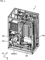
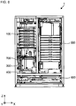
- FIG. 1 to 6 shows a returned medicine supplying apparatus (medicine sorting apparatus) 1 according to an embodiment of the present invention.
- the returned medicine supplying apparatus 1 includes a receiving part 100, an elevating part 200, an recognizing part 300, a non-stored medicine arrangement part 400, a storing part 500 and a dispensing part 600.
- the returned medicine supplying apparatus 1 further includes an orthogonal type robot 700, a scalar type robot 800 and a support tray 900.
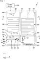
- the returned medicine supplying apparatus 1 includes a control device 1000 schematically shown in Fig. 1 .
- the control device 1000 totally controls an operation of the returned medicine supplying apparatus 1 based on an input from a control panel 1001 (which includes a display 1002) illustrated in Fig. 4 , an input from a sensor or a camera or the like.
- the returned medicine supplying apparatus 1 recognizes characteristics such as a shape, a size (a length L1 and a diameter or a width W1), a type and an expiration date of each of returned medicines 2 such as an ampule 2A, a vial 2B and a resin ampule 2C (see Fig. 8 ).
- characteristics such as a shape, a size (a length L1 and a diameter or a width W1), a type and an expiration date of each of returned medicines 2 such as an ampule 2A, a vial 2B and a resin ampule 2C (see Fig. 8 ).
- a label 3 on which a barcode or literal information containing information on the type, the expiration date and the like is printed adheres to each of the returned medicines 2.
- the returned medicine supplying apparatus 1 reads these information indicated on the label 3.
- the returned medicine supplying apparatus 1 associates the recognized returned medicine 2 with identification information of this returned medicine 2 (the identification information is unique information added to each of the returned medicines 2) to temporarily store the recognized returned medicine 2 and dispense the recognized returned medicine 2 based on prescription data (received from a host system (HIS: Hospital Information System) which is, for example, an electronic health record system).
- a host system HIS: Hospital Information System
- a storing area is defined according to the size of the returned medicine 2 to be stored.
- To store the returned medicine 2 is performed so that the returned medicine 2 is stored in the defined storing area and each of the returned medicines 2 can be taken from at the time of dispensing each of the returned medicines 2.
- the returned medicine supplying apparatus 1 discharges one or more of the returned medicines 2 whose expiration dates have expired.
- the receiving part 100 is arranged on the left upper and front side when the returned medicine supplying apparatus 1 is viewed from the front side.
- the receiving part 100 includes fixed rack members 101 arranged so as to face each other in the horizontal direction (the X direction in the drawings).
- a plurality of pairs of rail grooves 101a, 101a for holding a plurality of returned goods trays (receiving containers) 4 in a state that the plurality of returned goods trays 4 are arranged in multiple stages are formed on the rack members 101.
- the returned goods tray 4 includes a tray main body 4a opening toward the upper side in the drawing and a flange portion 4b provided on an upper end of the tray main body 4a.
- the returned medicines 2 for example, the ampule 2A, the vial 2B and the resin ampule 2C
- the returned medicines 2 have different characteristics such as the shape, the size (the length L1 and the width W), the type and the expiration date.
- directions and postures of the returned medicines 2 contained in the returned goods tray 4 are not aligned, thus the directions and the postures of the returned medicines 2 are different from each other.
- the returned medicines 2 contained in the returned goods tray 4 are in a non-aligned state.
- the direction of each of the returned medicine 2 means a direction in which a longitudinal direction of the returned medicine 2 (an axial line A of the returned medicine 2) in the X-Y plane in the drawing extends.
- the language of "the direction of the returned medicine 2" often contains a direction in which a tip end 2a and a base end 2b of the returned medicine 2 are directed in addition to the direction in which the axial direction A of the returned medicine extends.
- the characteristics such as the shape, the size, the type and the expiration date of each of the returned medicines 2 contained in the returned goods tray 4 may be unified.
- the directions and the postures of the returned medicines 2 contained in the returned goods tray 4 may be aligned.
- the returned medicines 2 are contained in the returned goods tray 4 so as not to be partially overlapped with each other.
- the flange-like 4b of the returned goods tray 4 is supported by the rail grooves 101a, 101a respectively formed on the rack members 101.
- Each of the rail grooves 101a, 101a is formed so as to pass through from a front side end to a rear side end of each of the rack members 101 in the X direction in the drawing of the rack members 101.
- an operator such as a medical staff can take the returned goods tray 4 into and from the rail grooves 101a, 101a from the front side of the returned medicine supplying apparatus 1.
- the elevating part 200 described below can take the returned goods tray 4 into and from the rail grooves 101a, 101a from the rear side of the returned medicine supplying apparatus 1.
- the elevating part 200 is arranged on the left rear side when the returned medicine supplying apparatus 1 is viewed from the front side.
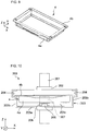
- the elevating part 200 includes a fixed linear motion guide 201 extending in the Z direction, a carriage 202 elevating along the linear motion guide 201 and a table 203 mounted on the carriage 202.
- the table 203 includes a bottom portion 203a, lateral portions 203b, 203b respectively provided on the right side and the left side of the bottom portion 203a and an end portion 203c provided on the rear side of the bottom portion 203a (the rear side of the Y direction).
- the table 203 opens toward the front side (the front side of the Y direction).
- the table 203 opens toward the rear side (the rear side of the Y direction).
- Rail grooves 204, 204 are respectively formed on the lateral portions 203b, 203b.
- the flange-like 4b of the returned goods tray 4 is supported by the rail grooves 204, 204. This makes it possible to hold the returned goods tray 4 in the table 230.
- a fixed linear motion guide 205 extending in the depth direction of the returned medicine supplying apparatus 1 (the Y direction) is provided on the bottom portion 203a. Further, a base end of a hook 207 is fixed to a carriage 206 which can horizontally move along this linear motion guide 205.
- the elevating part 200 can take one of the returned goods trays 4 from the receiving part 100 to move the one returned goods tray 4 down to a height position (schematically represented by a symbol H in Fig. 1 ) same as a height position of the recognizing part 300 described below (this operation is referred to as a brought-back tray taking operation). Further, the elevating part 200 can return the one returned goods tray 4 from the height position H same as the height position of the recognizing part 300 into the receiving part 100 (this operation is referred to as a brought-back tray returning operation).
- the table 203 (carriage 202) is moved up to a position slightly lower than the rail grooves 101a, 101a of the receiving part 100 in which the returned goods tray 4 to be taken is held.
- the hook 207 (carriage 206) is moved toward the front side (the front side of the Y direction) from the side of the end portion 203c of the table 203.
- the table 203 is slightly moved up. As a result, the hook 207 is moved into a space between the flange portion 4b of the returned goods tray 4 (a portion on the rear side in the drawings) and the tray main body 4a.
- the hook 207 is moved back toward the rear side (the rear side of the Y direction) so that the hook 207 is moved toward the side of the end portion 203c of the table 203. Due to this backing movement of the hook 2007, the flange portion 4b is pulled into the rail groove 204 to transfer and place the returned goods tray 4 from the receiving part 100 onto the table 203. Finally, the table 203 (carriage 202) is moved down to the position represented by the symbol H (in Fig. 1 ).
- the table 203 (carriage 202) is moved up from the position represented by the symbol H to a height corresponding to the rail grooves 101a, 101a (which have not held the returned goods tray 4) in which the returned goods tray 4 is to be returned.
- the hook 207 (carriage 206) is then moved toward the front side (the front side of the Y direction) from the side of the end portion 203c of the table 203.
- the flange portion 4b of the returned goods tray 4 pushed by the hook 207 is moved out of the rail grooves 204, 204 and moved into the rail grooves 101a, 101a of the receiving part 100.
- the table 203 is slightly moved down.
- the hook 207 is downwardly moved out of the gap between the flange portion 4b of the returned goods tray 4 (the portion on the rear side in the drawings) and the tray main body 4a. Finally, the hook 207 is moved back toward the rear side so that the hook 207 is moved toward the side of the end portion 203c of the table 203.
- the orthogonal type robot 700 (a first picking part) includes a suctioning nozzle 701 for suctioning the returned medicine 2 with vacuum supplied from a vacuum source (not shown in the drawings) so that the returned medicine 2 can be released.
- a suctioning pad 702 made from rubber is attached to a tip end of the suctioning nozzle 701.
- the orthogonal type robot 700 is configured so that a range in which the suctioning nozzle 701 can suction and hold the returned medicine 2 or release the suctioned and held returned medicine 2 by releasing the suctioning contains an entire range of the elevating part 200 (the returned goods tray 4 positioned at the described height position H), the recognizing part 300 and the non-stored medicine positioning part 400.
- the orthogonal type robot 700 (suctioning nozzle 701) can suction and hold the returned medicine 2 to take the returned medicine 2 from the returned goods tray 4 held by the table 203 of the elevating part 200 (positioned at the height position H) and transfer the returned medicine 2 to an after-mentioned temporarily placing part (a first recognizing part) 301 included in the recognizing part 300. Further, the orthogonal type robot 700 can suction and hold the returned medicine 2 to take the returned medicine 2 from the temporarily placing part 301 and transfer the returned medicine 2 to an after-mentioned label reading part (a second recognizing part) 302 included in the recognizing part 300. Furthermore, the orthogonal type robot 700 can suction and hold the returned medicine 2 to take the returned medicine 2 from the label reading part 302 and transfer the returned medicine 2 to the non-stored medicine arrangement part 400.
- the orthogonal type robot 700 includes a fixed Y-axis beam 703 extending in the depth direction of the returned medicine supplying apparatus 1 (the Y direction) on the lower side than the receiving part 100 and a carriage 704 which can move along this Y-axis beam 703.
- An X-axis beam 705 extending in the width direction of the returned medicine supplying apparatus 1 (the X direction) is fixed to the carriage 704.
- a carriage 706 which can move on the X-axis beam 705 is provided and a head 707 is mounted on this carriage 706.
- An elevating rod 708 which can elevate due to a ball screw mechanism is provided at the head 707.
- the suctioning nozzle 701 is held by a bracket 709 fixed to a lower end of the elevating rod 708.
- the suctioning nozzle 701 can rotate with respect to the bracket 709 around the Z axis.
- a spring 701 illustrated in only Fig. 11 is intervened between the bracket 709 and the suctioning nozzle 701 and thus the suctioning nozzle 701 can be elastically moved up with respect to the bracket 709.
- a position sensor (not shown in the drawings) for detecting a relative height position (a position in the Z direction) of the suctioning nozzle 701 with respect to the bracket 709 is mounted on the carriage 706.
- the returned medicine 2 suctioned and held by the suctioning nozzle 701 can be moved in the X direction by the linear motion of the carriage 706, in the Y direction by the linear motion of the carriage 704 and in the Z direction by the elevating of the elevating rod 708. Further, the returned medicine 2 suctioned and held by the suctioning nozzle 701 can be rotated around an axial line of the suctioning nozzle 701 (the Z axis) by the rotation of the suctioning nozzle 701 with respect to the bracket 709.
- the recognizing part 300 includes a lighting part 303 and a camera 304 (a first photographing part).
- the lighting part 303 and the camera 304 are positioned on the upper side of the elevating part 200.
- the recognizing part 300 includes the temporarily placing part 301 constituting one example of the first recognizing part of the present invention in cooperation with the camera 304 and the label reading part (one example of the second recognizing part of the present invention) 302.
- the temporarily placing part 301 and the label reading part 302 are arranged on the left lower and front side when the returned medicine supplying apparatus 1 is viewed from the front side. Further, the temporarily placing part 301 and the label reading part 302 are positioned on the lower side of the receiving part 100.
- the temporarily placing part 301 includes a semi-transparent plate 305 on which the returned medicine 2 is to be placed, a lighting part 306 arranged on the lower side of this semi-transparent plate 305 and a camera 307 (a second photographing part) positioned on the upper side of the semi-transparent plate 305.
- the label reading part 302 includes an endless belt 308 which is to be rotary-driven and a roller 309 arranged on this endless belt 308.
- the endless belt 308 and the roller 309 are rotated, the returned medicine 2 is rotated around an axial line A of the returned medicine 2 in the longitudinal direction thereof.
- the label reading part 302 includes a lighting part 310 and a camera 311 (one example of a third photographing part of the present invention) illustrated in only Fig. 1 .
- the label reading part 302 includes a barcode reader (a first barcode reader) 312.
- the non-stored medicine arrangement part 400 includes two non-stored medicine arrangement boxes 401, 402 arranged adjacent to the temporarily placing part 301.
- Each of these non-stored medicine arrangement boxes 401, 402 includes an arrangement groove, which is similar to an arrangement groove of the storing tray (the storing container) 5 described below, for holding the returned medicines 2.
- the returned goods tray 4 is transferred and placed from the receiving part 100 onto the table 203 of the elevating part 200. After transferring and placing the returned goods tray 4, the table 203 is moved down to the height position H (see Fig. 1 ). After the table 203 has been moved down to the height position H, an recognition process by the recognizing part 300 is started. First, the returned goods tray 4 is photographed by the camera 304 with irradiating the returned goods tray 4 on the table 203 from the upper side with illumination light from the lighting part 303 (it is preferable that this illumination light is light having high directionality).
- a position of the returned medicine 2 in the returned goods tray 4 the direction of the returned medicine 2 (which is a direction in which the axial line A extends in the X-Y plane and which does not contain a direction in which the tip end 2a and the base end 2b are directed) and a substantially intermediate position of the returned medicine 2 (a position suitable for suctioning and holding the returned medicine 2) are recognized from an elongated area where the returned medicine 2 contained in an image photographed by the camera 304 strongly reflects the illumination light.
- the suctioning nozzle 701 of the orthogonal type robot 700 suctions and holds the returned medicines 2 in the returned goods tray 4 one by one to transfer and place the returned medicines 2 onto the semi-transparent plate 305 of the temporarily placing part 301 (see Fig. 12 ).
- the suctioning nozzle 701 adjusts the direction of the suctioned and held returned medicine 2 by utilizing the rotation of the suctioning nozzle 701 around the axial line thereof (the Z axis).
- the photographing by the camera 307 is performed. Based on an image photographed by the camera 307, the shape, the size and the direction (including the direction in which the axial line A of the returned medicine 2 in the X-Y plane extends and the tip end 2a and the base end 2b are directed) of the returned medicine 2 are recognized (details will be described below).
- a suctioning position for the returned medicine 2 (a position where the returned medicine 2 is suctioned by the suctioning nozzle 701 of the orthogonal type robot 700 or the suctioning nozzle 801 of the scalar type robot 800) is calculated. This method for calculating the suctioning position for the returned medicine 2 will be described below.
- the suctioning nozzle 701 of the orthogonal type robot 700 suctions and holds the returned medicine 2 on the semi-transparent plate 305 to transfer and place the returned medicine 2 onto the label reading part 302.
- the suctioning nozzle 701 adjusts the direction of the suctioned and held returned medicine 2 by utilizing the rotation of the suctioning nozzle 701 around the axial direction thereof (the Z axis).
- the returned medicine 2 is rotated around the axial line A thereof (see Fig. 13 ) by the rotations of the endless belt 308 and the roller 309 (details will be described below).
- the camera 311 photographs this rotating returned medicine 2 with irradiating the returned medicine 2 with illumination light from the lighting part 310.
- the literal information related to the expiration date or the like indicated on the label 3 of the returned medicine 2 is recognized and the posture of the returned medicine 2 around the axial line A is recognized.
- the barcode contained in the label 3 is read by the barcode reader 312.
- the type and the expiration date of the returned medicine 2 are recognized.
- the recognition of the type and the expiration date of the medicine may be performed based on only one of the image photographed by the camera 311 and the barcode read by the barcode reader 312. For example, in the case where the barcode contained in the label 3 of the returned medicine 2 contains the type and the expiration date of the returned medicine 2, the camera 311 may not be provided and only the barcode reader 312 may be provided. In this case, it is possible to recognize the type and the expiration date of the returned medicine 2 by reading the barcode with the barcode reader 312.
- the rotations of the endless belt 308 and the roller 309 are stopped so that the rotation of the returned medicine 2 around the axial line A is stopped in a posture that the barcode of the label 3 is directed toward the upper side (the Z direction). It is possible to check whether or not the label 3 is directed toward the upper side based on the photographed image of the camera 311.
- the returned medicine 2 has an area in which the suctioning nozzle 801 of the after-mentioned scalar type robot 800 cannot suction the returned medicine 2 (for example, the case where the returned medicine 2 has an area in which a burr exists such as a lateral surface of the resin ampule 2C or an area in which the label is likely to be peeled when the label in this area is suctioned), it is preferable that the rotation of the returned medicine 2 is stopped so that this area is not directed toward the upper side.
- this suctioning impossible area is preliminarily registered (preliminarily stored) in an after-mentioned medicine master in a state that the suctioning impossible area is associated with the medicine.
- the returned medicine 2 is rotated around the axial line A by not a pair of rollers but the rotations of the endless belt 308 and the roller 309.
- the combination of the endless belt 308 and the roller 309 can rotate the returned medicine 2 having a broader range of the shape, the size and the type of the returned medicine 2 compared with the case of using the pair of rollers.
- the label reading part 302 takes a configuration in which the returned medicine 2 is rotated by the pair of rollers, there is a case where the returned medicine 2 is moved toward one of two directions along rotational axes of the pair of rollers due to a relative inclination or misalignment between the rotational axes of the pair of rollers.
- this moving direction of the returned medicine 2 it is required to exactly adjust the relative inclination or misalignment between the rotational axes of the pair of rollers.
- a rotational axis of the roller 309 is inclined with respect to a travelling direction of the endless belt 308. Due to such an arrangement of the endless belt 308 and the roller 309, it is possible to limit the moving direction of the returned medicine 2 in a width direction of the endless belt 308 to one direction (the lower direction in Fig. 13 ). As a result, it is possible to make the position of the returned medicine 2 constant in the label reading part 302.
- this returned medicine 2 is suctioned and held by the suctioning nozzle 701 of the orthogonal type robot 700 to transfer and place the returned medicine 2 into one of the non-stored medicine arrangement boxes 401, 402 of the non-stored medicine arrangement part 400.
- one of the returned goods trays 4 of the receiving part 100 may be used as a tray for the non-stored and arranged medicine and the returned medicine 2 in the one of the non-stored medicine arrangement boxes 401, 402 may be returned to this returned goods tray 4.
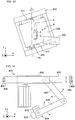
- the scalar type robot 800 (a second picking part) includes a suctioning nozzle 801 for suctioning the returned medicine 2 with vacuum supplied from a vacuum source (not shown in the drawings) so that the returned medicine 2 can be released.
- a suctioning pad 802 made from rubber is attached to a tip end of the suctioning nozzle 801.
- the scalar type robot 800 is configured so that a range in which the suctioning nozzle 801 can suction and hold the returned medicine 2 or release the suctioned and held returned medicine 2 by releasing the suctioning contains the label reading part 302 of the recognizing part 300, all ranges of all storing trays 5 included in the storing part 500 and an entire range of a dispensing tray 8 arranged at a dispensing position described below.
- the scalar type robot 800 (suctioning nozzle 801) can suction and hold the returned medicine 2 to take the returned medicine 2 from the label reading part 302 of the recognizing part 300 and transfer the returned medicine 2 to the after-mentioned storing tray 5 included in the storing part 500. Further, the scalar type robot 800 can suction and hold the returned medicine 2 to take the returned medicine 2 from the storing tray 5 and transfer the returned medicine 2 to the after-mentioned dispensing tray 8 included in the dispensing part 600.
- the scalar type robot 800 includes a pair of fixed linear motion guides 803, 803 extending in the height direction of the returned medicine supplying apparatus 1 (the Z direction) and carriages 804, 804 which can respectively move on these linear motion guides 803, 803. Due to the carriages 804, 804, end portions of an X-axis beam 805 extending in the width direction of the returned medicine supplying apparatus 1 (the X direction) are supported. A base 806 is fixed to the X-axis beam 805.
- a base end portion of a first arm 807 connected to the base 806 can pivotally move around the Z axis and a base end portion of a second arm 807 connected to a tip end portion of the first arm 807 can also pivotally move around the Z axis.
- a head 809 is attached to a tip end portion of the second arm 807.
- the suctioning nozzle 801 is held by a bracket 810 fixed to the head 809.
- the suctioning nozzle 801 is rotated with respect to the bracket 810 around the Z axis.
- a spring 811 illustrated in only Fig. 15 is intervened between the bracket 810 and the suctioning nozzle 801.
- the suctioning nozzle 801 can be elastically moved up with respect to the bracket 810.
- a barcode reader 812 (a second barcode reader) illustrated in only Fig. 14 and a presence detecting sensor 820 for detecting the returned medicine 2 are mounted on the head 809.
- the barcode reader 812 is mounted at a position shifting to the lateral direction with respect to the suctioning nozzle 801 so that the barcode reader 812 can read the barcode of the label 3 adhering to the returned medicine 2 positioned on the lower side of the suctioning nozzle 801 from the diagonally upward direction.
- the barcode reader 812 is arranged so as to face the barcode of the label 3 adhering to the returned medicine 2 when the suctioning nozzle 801 is positioned on the upper side of the target returned medicine 2 in the same as the positional relationship of the barcode reader 312 with respect to the returned medicine 2 in the label reading part 302.
- the presence detecting sensor 820 is a reflecting type photoelectric sensor.
- the presence detecting sensor 820 emits light toward a lower area below the suctioning nozzle 801 and receives reflected light of this light to detect whether or not the returned medicine 2 is present in the lower area below the suctioning nozzle 801.
- the returned medicine 2 suctioned and held by the suctioning nozzle 801 is moved in the Z direction due to the linear motion of the X-axis beam 805 (carriage 804) and moved in the X-Y plane due to the pivotal movements of the first arm 807 and the second arm 807. Further, the returned medicine 2 suctioned and held by the suctioning nozzle 801 is rotated around the axial line of the suctioning nozzle 801 (the Z axis) due to the rotation of the suctioning nozzle 801 with respect to the bracket 810.
- the support tray 900 is fixed to a lower end of a rod 901 which can elevate with respect to the base 806 of the scalar type robot 800.
- the support tray 900 includes the same arrangement groove for holding the returned medicine 2 as that of the storing tray 5 described below.
- the support tray 900 is elevated to a height position where the support tray 900 approaches to the returned medicine 2 suctioned and held by the suctioning nozzle 801 and a height position where the support tray 900 separates from the returned medicine 2 suctioned and held by the suctioning nozzle 801.
- the scalar type robot 800 uses the first arm 807 and the second arm 808 to move the suctioning nozzle 801 in the horizontal direction to position the suctioning nozzle 801 on the upper side of the support tray 900.
- the head 809 is rotated so that the direction of the suctioned returned medicine 2 coincides with a direction of the arrangement groove of the support tray 900.
- the rod 901 is moved toward the upper direction to transfer the support tray 900 to the height position where the support tray 900 approaches to the returned medicine 2 from the height position where the support tray 900 separates from the returned medicine 2.
- the returned medicine 2 dropped into the support tray 900 may be re-suctioned and transferred by the suctioning nozzle 801.
- a pressure sensor (not shown in the drawings) provided at the suctioning nozzle 801 may detect that the suctioning of the suctioning nozzle 801 is unintentionally released.
- the returned medicine 2 is transferred in a state that the direction of the returned medicine 2 coincides with the direction of the arrangement groove on the support tray 900 as described above, the returned medicine 2 drops into the arrangement groove provided immediately below the suctioning nozzle 801 without changing the direction and the posture of the returned medicine 2 when the suctioning of the suctioning nozzle 801 is unintentionally released.
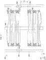
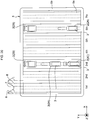
- the storing part 500 is arranged on the right and rear side when the returned medicine supplying apparatus 1 is viewed from the front side.
- the storing part 500 includes a linear motion guide 501 extending in the Z direction.
- Holding frames 502 for holding each of the storing trays 5 so that each of the storing trays 5 can be taken are provided on this linear motion guide 501 so that the holding frame 502 can be elevated.
- the holding frames 502 are arranged in multiple stages so as to overlap with each other in the Z direction.
- Linear motion guides 503, 503 extending in the Z direction are respectively placed on both sides of the storing trays 5 arranged in the multiple stages.
- Carriages 504, 504 respectively elevating on these linear motion guides 503, 503 are provided.
- Lifting members 505 which can be moved to a retracting position shown in Fig. 16 and a protruding position shown in Fig. 17 are respectively mounted on the carriages 504.
- Other lifting members 505 are also provided on the rear side in the drawings. Further, a plurality of lifting members 505 may be arranged in multiple stages.
- the suctioning nozzle 801 of the scalar type robot 800 can access the storing tray 5, which is held by the holding frame 502 provided just below the holding frame 502 below which the lifting members 505 are inserted, through this gap S.
- the suctioning nozzle 801 of the scalar type robot 800 can perform an operation for transferring and placing the returned medicine 2 and an operation for suctioning and holding the returned medicine 2 to take the returned medicine 2 with respect to all of the storing trays 5.
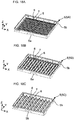
- the storing tray 5 contains a storing tray 5A (S-size) suitable for storing a relatively small size returned medicine 2, a storing tray 5B (M-size) suitable for storing a middle size returned medicine 2 and a storing tray 5B (L-size) suitable for storing a relatively large size returned medicine 2.
- the storing part 500 includes at least one of these three types storing trays 5A to 5B.
- Each of the storing trays 5 (5A to 5C) includes a tray main body 5a opening toward the upper side in the drawings and a flange portion 5b provided on an upper end of the tray main body 5a.
- a plurality of protruding portions (protrusions) 6 extending in the depth direction of the returned medicine supplying apparatus 1 (the Y direction) and arranged so as to be spaced apart from each other in the width direction of the returned medicine supplying apparatus 1 (the X direction) are formed on a bottom portion of the tray main body 5a.
- Linear arrangement grooves (concave portions) 7 are respectively formed between the adjacent protruding portions 6 and the returned medicines 2 are to be stored in the arrangement grooves 7.
- the three types storing trays 5A to 5B includes the protruding portions having different sizes (heights and widths), sizes (depths and widths) of the arrangement grooves 7 are different from each other as is clear by referring to Figs. 19A to 19C . Due to these differences of the sizes of the arrangement grooves 7, a size of the returned medicine 2 suitable for being stored differs for each type of the three types storing trays 5A to 5B as described above.
- the dispensing part 600 includes a conveying mechanism 601.
- the conveying mechanism 601 transfers the dispensing tray 8 from an inlet port 602 schematically illustrated in Fig. 1 to a dispensing position (a position on the front side in the drawings for the storing part 500) to position the dispensing tray 8 and conveys the dispensing tray 8 after the dispensing operation has been completed from an outlet port 603 schematically illustrated in Fig. 1 .
- the returned medicine 2 in the label reading part 302 is suctioned and held by the suctioning nozzle 801 of the scalar type robot 800.
- a storing area is defined according to at least the size of the returned medicine 2.
- a storing position of the returned medicine 2 (a position in the storing tray 8 at which the returned medicine 2 is to be stored) and a range occupied by the returned medicine 2 when the returned medicine 2 is stored are defined with respect to the returned medicine 2 suctioned and held by the suctioning nozzle 801 according to at least the size of the returned medicine 2.
- the range occupied by the returned medicine 2 when the returned medicine 2 is stored in the storing area corresponds to the length L1 and the width W of the returned medicine 2.
- a range indicated at the time of storing the returned medicine 2 contains a margin for preventing the returned medicine 2 from interfering with other returned medicines 2.
- the plurality of storing trays 5 of the storing part 500 are searched to find which storing tray 5 and which arrangement groove 7 of the storing tray 5 can be used to store and arrange the returned medicine 2 suctioned and held by the suctioning nozzle 801 therein. According to this searching result, one of the storing trays 5 and one of the arrangement grooves 7 (the storing position of the returned medicine 2) in which the returned medicine 2 is to be stored are decided.
- the arrangement grooves 7 other than the third arrangement groove 7 become candidates for the storing position at which the returned medicine 2 suctioned by the suctioning nozzle 801 is to be stored.
- the sixth groove can be the candidate for arranging the returned medicine 2 suctioned and held by the suctioning nozzle 801 if a length between these two returned medicines 2 is equal to or longer than the above-described range indicated at the time of storing the returned medicine 2 for the returned medicine 2 being stored.
- the returned medicine 2 takes the posture in which the label 3 is directed toward the upper side.
- the suctioning nozzle 801 of the scalar type robot 800 suctions and holds the returned medicine 2 with keeping the posture of the returned medicine 2 in which the label 3 is directed toward the upper side to transfer and place the returned medicine 2 into the appropriate arrangement groove 7 of the appropriate storing tray 5, that is into the decided storing area decided as described above.
- the storing part 500 is configured to be capable of forming the gap S between the holding frames 502.
- the suctioning nozzle 801 of the scalar type robot 800 being suctioning and holding the returned medicine 2 can freely access the storing tray 5 held by any one of the holding frames 502 arranged in the multiple stages to place the suctioned and held returned medicine 2.
- the storing tray 5 of the storing part 500 contains the three types storing trays 5A to 5B having the different sizes.
- the control device 1000 can control the recognizing part 300, it is possible to store the returned medicine 2 whose recognition has completed into the storing part 500 without the limitation on the size of the returned medicine 2 to be stored.
- the control device 1000 stores the described storing area for each of the returned medicines 2 in a state that the storing area for each of the returned medicines 2 is associated with the identification information of each of the returned medicines 2. Namely, the control device 1000 stores information on the storing trays 5 and the positions of the storing trays 5 (the arrangement grooves 7 and the positions on the arrangement grooves 7) at which the returned medicines 2 have been arranged in a state that the storing area for each of the returned medicines 2 is associated with the identification information of each of the returned medicines 2. Further, the control device 1000 stores the type and the expiration date of each of the returned medicines 2 in a state that the type and the expiration date of each of the returned medicines 2 are associated with the identification information of each of the returned medicines 2.
- the suctioning nozzle 801 of the scalar type robot 800 suctions and holds the returned medicine 2 from the storing tray 5 of the storing part 500 to transfer and place the returned medicine 2 onto the storing tray 5 arranged at the dispensing position.
- the dispensing operation is performed based on the prescription data received by the returned medicine supplying apparatus 1 from the host system (HIS: Hospital Information System) which is the electronic health record system, for example.
- the host system HIS: Hospital Information System
- the type and the expiration date of each of the returned medicines 2 stored in the storing part 500 and the recognition data of each of the returned medicines 2 are stored in a state that the type and the expiration date of each of the returned medicines 2 are associated with the identification data of each of the returned medicines 2, and the positions in the storing part 500 where each of the returned medicine supplying apparatuses 1 is stored are also stored in a state that the positions are associated with the identification data of each of the returned medicines 2.
- the control device 1000 includes the medicine master storing the type, the expiration date and the storing area of each of the returned medicines 2 stored in the storing part 500 and the identification data of each of the returned medicine 2 in a state that the type, the expiration date and the storing area are associated with the identification data.
- the gap S can be formed between the adjacent storing trays 5 arranged in the multiple stages as described above, the suctioning nozzle 801 can freely suction and hold even the returned medicine 2 stored in any one of the storing trays 5 arranged in the multiple stages as required.
- the medicine master if it is confirmed that the medicine contained in the prescription data is the returned medicine 2 stored in the storing part 500, it is possible to dispense the returned medicine 2 according to the prescription data without any limitations. Further, it is possible to efficiently dispense the returned medicine 2 according to the prescription data, that is, for example, it is possible to dispense one of the returned medicines 2 whose expiration date is earliest among the same type of the returned medicines 2. Furthermore, as a result of referring to the medicine master, if it is confirmed that the medicine contained in the prescription data is not stored in the storing part 500, it is possible to perform a process such as a process of allowing the display 1002 of the control panel 1001 to display necessary information.
- the returned medicine supplying apparatus 1 of this embodiment it is possible to automatically recognize the returned medicines 2 having a variety of different characteristics such as the type, the shape, the size and the expiration date and supplied in the non-aligned state to store the returned medicines 2 with ensuring a high degree of freedom and freely dispense the returned medicines 2 according to the prescription data.
- the shape and the size of the returned medicine 2 are recognized (information on the shape and the size is obtained).
- the returned medicine 2 is placed on a placing surface 305a of the semi-transparent plate 305 (a plane surface on the side of the camera 307) so that the longitudinal axis A of the returned medicine 2 is parallel to the placing surface 305a as shown in Figs. 1 and 12 .
- the returned medicine 2 placed on the semi-transparent plate 305 is photographed by the camera 307 provided on the upper side of the semi-transparent plate 305 in a state that the light is emitted from the lower side by the lighting part 306 arranged on the lower side of the semi-transparent plate 305.
- the control device 1000 is configured to obtain the information on the shape and the size of the returned medicine 2 based on the image photographed by the camera 307. Namely, the control device 1000 serves as the recognizing part for recognizing the shape and the size of the returned medicine 2.
- control device 1000 is configured to perform an image processing on the image of the camera 307 in which the returned medicine 2 is shown in order to obtain the information on the shape and the size of the returned medicine 2 (the control device 1000 includes an image processing part). For example, as the image processing performed on the image of the camera 307, an edge detecting process for detecting edges of a form of the returned medicine 2 shown in the image of the camera 307 and a binarization process for binarizing (black-and-white forming) the image of the camera 307 are performed. Based on an image subjected to the edge detecting process and an image subjected to the binarization process, the control device 1000 obtains the information on the shape and the size of the returned medicine 2.
- control device 1000 is configured to determine whether or not the shape of the returned medicine 2 is a shape of the medicine to be treated by the returned medicine supplying apparatus 1 based on the obtained shape of the returned medicine 2.
- the returned medicine 2 to be returned through the returned goods tray 4 contains a medicine having a shape engaging between the endless belt 308 and the roller 309 in the label reading part 302, a medicine having a shape which cannot be held by the scalar type robot 800 and a medicine having a shape which cannot be stored in the storing part 500, that is a medicine having a shape which cannot be treated by the returned medicine supplying apparatus 1 due to a structural reason thereof.
- a medicine in a state that the medicine is contained in a bag body or a box body, a medicine partially broken, a medicine whose label is partially peeled, a medicine whose partially peeled label adheres to another medicine and the like can be considered.
- the medicine is treated as a medicine not to be treated (treated as a non-stored medicine).
- the non-stored medicine is returned to the returned goods tray 4 for the non-stored medicine through the non-stored medicine arrangement boxes 401, 402 of the non-stored medicine arrangement part 400.
- the label reading part 302 includes the endless belt 308 on which the returned medicine 2 is to be placed and the roller 309 which makes contact with the returned medicine 2 placed on the endless belt 308 to rotate the returned medicine 2 around the axial line A of the returned medicine 2.
- the label reading part 302 further includes a belt driving part (not shown in the drawings) for driving the endless belt 308 and a roller driving part (not shown in the drawings) for driving the roller 309.
- Each of the belt driving part and the roller driving part is, for example, a motor and controlled by the control device 1000.
- the roller 309 is arranged on the upper side of the endless belt 308 through a space (for example, a space of 1 mm). Further, the travelling direction F of the endless belt 308 non-orthogonally crosses the extending direction of the rotational center line Rc of the roller 309 (the Y-axis direction). For example, in this embodiment, an angle formed between the extending direction of the rotational center line Rc of the roller 309 and the travelling direction F of the endless belt 308 is in the range of 5 to 15 degrees.
- the travelling direction F of the endless belt 308 is a direction in which the returned medicine 2 placed on the endless belt 308 approaches to the roller 309.
- a rotational direction of the roller 309 is a rotational direction whose rotational speed becomes reverse with respect to an X-direction component of the travelling direction F of the endless belt 308 in a facing area where the roller 309 faces the endless belt 308.
- the endless belt 308 and the roller 309 are driven and controlled by the control device 1000 through the belt driving part and the roller driving part so that a movement speed of the endless belt 308 and the rotational speed of the roller 309 are equal to each other in the facing area between the endless belt 308 and the roller 309.
- the returned medicine 2 placed on the endless belt 308 is conveyed by the endless belt 308 and makes contact with the roller 309.
- the returned medicine 2 is kept in a state that the returned medicine 2 makes contact with the roller 309 and positioned in the X-axis direction.
- the returned medicine 2 (in particular, the ampule 2A and the resin ampule 2C) is preferably placed on the endless belt 308 by the orthogonal type robot 700 in a state that the direction of the returned medicine 2 is directed so that the base end 2b of the returned medicine 2 faces the stopper 317 when the returned medicine 2 makes contact with the roller 309.
- the ampule 2A or the resin ampule 2C is placed on the endless belt 308 in a state that the direction thereof is directed so that the tip end 2a (the head portion 2d) thereof is positioned on the side of the stopper 317, there is a possibility that a corner of the body portion 2c on the side of the base end 2b makes contact with the roller 309 in first when the conveying by the endless belt 308 is started and the direction of the ampule 2A or the resin ampule 2C is changed on the endless belt 308 by reaction of this contact, and thereby the head portion 2d thereof gets into a space between the endless belt 308 and the roller 309.
- the returned medicine 2 is preferably placed on the endless belt 308 by the orthogonal type robot 700 in a state that the direction of the returned medicine 2 is directed so that the base end 2b thereof faces the stopper 317 when the returned medicine 2 makes contact with the roller 309.
- the returned medicine 2 which has contacted with the roller 309 is guided by the roller 309 and moved in the extending direction of the rotational center line Rc of the roller 309 (the Y-axis direction).
- one end portion of the returned medicine 2 in the extending direction of the axial line A thereof makes contact with the stopper 317, and thereby the returned medicine 2 is positioned in the extending direction of the rotational center line Rc of the roller 309 (the Y-axis direction).
- the returned medicine 2 is positioned with respect to the label reading part 302.
- the returned medicine 2 Due to the stopper 317 and the arrangement of the roller 309 with respect to the endless belt 308 in which the travelling direction F of the endless belt 308 and the extending direction of the rotational center line Rc of the roller 309 non-orthogonally cross each other, the returned medicine 2 is kept in a state that the returned medicine 2 is positioned with high accuracy.
- the travelling direction F of the endless belt 308 and the extending direction of the rotational center line Rc of the roller 309 orthogonally cross each other, there is a possibility that the returned medicine 2 which has contacted with the roller 309 is moved in the extending direction of the rotational center line Rc of the roller 309 and separated from the stopper 317. With taking account of this possibility, the travelling direction F of the endless belt 308 and the extending direction of the rotational center line Rc of the roller 309 non-orthogonally cross each other in order to keep this contacting state between the stopper 317 and the returned medicine 2.
- the returned medicine 2 Since the returned medicine 2 is kept in a state that the returned medicine 2 is positioned with the high accuracy, the returned medicine 2 can be kept in a field of view of the camera 311 of the label reading part 302 and the barcode of the label 3 of the returned medicine 2 can be kept in a state that the barcode is set in a readable area of the barcode reader 312, for example. As a result, it is possible to ensure high recognition accuracy with respect to the type and the expiration date of the returned medicine 2 by the camera 311 and the barcode reader 312.
- the control device 1000 is configured to obtain the information on the expiration date of the returned medicine 2 based on the image which is photographed by the camera 311 and in which the label 3 is shown (the control device 1000 includes an OCR part for recognizing the expiration date written on the label 3). Further, the control device 1000 is configured to obtain the information on the type of the returned medicine 2 based on the barcode read by the barcode reader 312. Namely, the control device 1000 serves as a part of the recognizing part 300 for recognizing the type and the expiration date of the returned medicine 2.
- the recognizing operation may be repeated until the number of the failures of the recognition operation reaches a predetermined number of times or a predetermined time passes due to the repeat of the recognizing operation (until the process time-outs), for example.
- the OCR part cannot recognize the expiration date written on the label 3 shown in the image photographed by the camera 311, a new image is photographed by the camera 311.
- the OCR part performs the recognizing operation on the expiration date of the label 3 shown in the newly photographed image.
- the OCR part performs the recognition operation for the expiration date of the label 3 shown in this image newly photographed.
- the recognizing operation fails the predetermined number of times (for example, the predetermined number of times is 18) or the process time-outs, the returned medicine 2 is treated as the non-stored medicine whose label 3 cannot be read (the returned medicine 2 is stored into the non-stored medicine arrangement boxes 401, 402 of the non-stored medicine arrangement part 400).
- control device 1000 is configured to control the rotational speed of the roller 309 based on an outer diameter of the returned medicine 2 set on the label reading part 302.
- the control device 1000 controls the roller driving part so as to decrease the rotational speed of the roller 309 as the outer diameter of the returned medicine 2 reduces.
- control device 1000 is configured to calculate the outer diameter of the returned medicine 2 based on the shape and the size (the size in the extending direction of the axial direction A) of the returned medicine 2 obtained from the image of the camera 307 of the temporarily placing part 301 of the recognizing part 300.
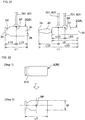
- a weight balance at the time of suctioning the vial 2B with the suctioning nozzle 701 or 801 is good when a substantially intermediate position of the length (total length L1) is set as a suctioning position SP.
- a substantially intermediate position of the length (total length L1) is set as a suctioning position SP.
- a weight balance at the time of suctioning the ampule 2A with the suctioning nozzle 701 or 801 is not good when a substantially intermediate position of the length (total length L1) is set as the suctioning position SP.
- the suctioning position SP for the returned medicine 2 is calculated based on the image photographed by the camera 307 of the temporarily placing part 301 according to the following procedures.
- an envelope 313 with respect to an external profile shape of the image (the image of the returned medicine 2 in planar view) photographed by the camera 307 is defined (a step 1 in Figs. 22 and 23 ). Further, a degree of convexity is calculated from this envelope 313 (the step 1 in Figs. 22 and 23 ). A value of the degree of convexity approaches to 1 as a ratio of straight lines in the envelope 313 surrounding the returned medicine 2 increases.
- the calculated value of the degree of convexity is equal to or more than a predetermined threshold value (for example, the threshold value can be set to be in the range of 0.8 to 0.9), it is possible to determines that the returned medicine 2 photographed by the camera 307 has a shape which can be estimated to be the vial 2B.
- a position located at an intermediate position of the total length L1 and an intermediate position of the width W is set as the suctioning position SP (a step 2 in Fig. 22 ).
- the calculated value of the degree of convexity is less than the predetermined threshold value described above, it is possible to determine that the returned medicine 2 photographed by the camera 307 has a shape which can be estimated to be the ampule 2A (or the resin ampule 2C), the following process is performed for setting an intermediate positon of the length L2 of the body portion 2a as the suctioning point SP.
- the envelope 313 is compared with the external profile shape of the image of the returned medicine 2 to extract a waist portion 314 corresponding to the neck portion (a portion whose diameter partially reduces) between the body portion 2c and the head portion 2d (a step 2 in Fig. 23 ).
- two areas 316a, 316b are created by removing the rectangular area 315 from the external profile shape of the image of the returned medicine 2 (a step 4 in Fig. 23 ). These areas 316a, 316b correspond to areas other than the waist portion 314 of the external profile shape of the image of the returned medicine 2. Further, one of these areas 316a, 316b corresponds to the body portion 2c of the returned medicine 2 and the other of these areas 316a, 316b corresponds to the head portion 2d of the returned medicine 2.
- Square measures of the areas 316a, 316b are compared with each other to remain one whose square measure is larger (corresponding to the body portion 2c) as a target to be processed and remove the other whose square measure is smaller (corresponding to the head portion 2d) from the target to be processed.
- the square measure of the area 316a is larger than the square measure of the area 316b, the area 316a remains as the target to be processed.
- a position located at an intermediate position of a length L2' of the area 316a (corresponding to the length L2 of the body portion 2c of the ampule 2A) and an intermediate position of a width W' (corresponding to the width W of the body portion 2c of the ampule 2A) is set as the suctioning position SP (a step 4 in Fig. 23 ).
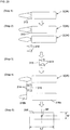
- the returned medicine 2 is placed onto the semi-transparent plate 305 in the temporarily placing part 301 of the recognizing part 300 by the orthogonal type robot 700.
- the returned medicine 2 placed on the semi-transparent plate 305 is photographed by the camera 307 arranged on the upper side of the returned medicine 2.
- the image of the camera 307 photographed at the step S102 is subjected to the image processing (the edge detecting process and the binarization process) by the control device 1000.
- the control device 1000 obtains the information on the shape of the returned medicine 2 placed on the semi-transparent plate 305 of the temporarily placing part 301 based on the image of the camera 307 subjected to the image processing at the step S103.
- the control device 1000 determines whether or not the shape of the returned medicine 2 placed on the semi-transparent plate 305 of the temporarily placing part 301 is the shape of the medicine to be treated based on the information on the shape of the returned medicine 2 obtained at the step S104. In the case where the shape of the returned medicine 2 is the shape of the medicine to be treated, the process shifts to a step S106. In the case where the shape of the returned medicine 2 is not the shape of the medicine to be treated (in the case where the shape of the returned medicine 2 is the shape of the medicine not to be treated), the process shifts to a step S115.
- the control device 1000 obtains the information on the size of the returned medicine 2 placed on the semi-transparent plate 305 of the temporarily placing part 301 based on the image of the camera 307 subjected to the image processing at the step S103.
- the control device 1000 determines whether or not the size of the returned medicine 2 placed on the semi-transparent plate 305 of the temporarily placing part 301 is the size of the medicine to be treated based on the information on the size of the returned medicine 2 obtained at the step S106. In the case where the size of the returned medicine 2 is the size of the medicine to be treated, the process shifts to a step S108. In the case where the size of the returned medicine 2 is not the size of the medicine to be treated (in the case where the size of the returned medicine 2 is the size of the medicine not to be treated), the process shifts to the step S 115.
- the returned medicine 2 on the temporarily placing part 301 is conveyed to the label reading part 302 by the orthogonal type robot 700. Due to this conveying, the returned medicine 2 is set in the label reading part 302.
- the control device 1000 adjusts the rotational speed of the roller 309 of the label reading part 302 which makes contact with the returned medicine 2 to rotate the returned medicine 2 based on the size (the outer diameter) of the returned medicine 2 obtained at the step S6.
- the control device 1000 determines whether or not the label 3 of the returned medicine 2 can be accurately read by the camera 311 or the barcode reader 312. In the case where the expiration date or the barcode indicating the type of the returned medicine 2 which are written on the label 3 can be accurately read, the process shifts to a step S111. In the case where the expiration date or the barcode cannot be accurately read, for example, in the case where the expiration date or the barcode is partially effaced, the process shifts to the step S115.
- the label 3 of the returned medicine 2 is accurately read by the camera 311 or the barcode reader 312 in the label reading part 302.
- the control device 1000 obtains the information on the type and the expiration date of the returned medicine 2 based on the label 3 of the returned medicine 2 read at the step S111.
- the control device 1000 determines whether or not the type and the expiration date of the returned medicine 2 set in the label reading part 302 are the type and the expiration date of the medicine to be treated based on the information on the type and the expiration date of the returned medicine 2 obtained at the step S112. Namely, the control device 1000 determines whether or not the type of the returned medicine 2 is the type stored in the medicine master and determines whether or not the expiration date has not expired or a sufficient time remains by the expiration date. In the case where both of the type and the expiration date are the type and the expiration date of the medicine to be treated, the process shifts to a step S114. In the case where at least one of the type and the expiration date is not the type or the expiration date of the medicine to be treated, the process shifts to the step S115.
- the returned medicine 2 in the label reading part 302 is conveyed to the storing part 500 by the scalar type robot 800 as the medicine to be treated.
- the returned medicine 2 whose shape, size, type and expiration date are the shape, the size, the type and the expiration date of the medicine to be treated is stored in the storing part 500.
- the returned medicine 2 whose shape is determined to be the shape of the medicine not to be treated at the step S105, the returned medicine 2 whose size is determined to be the size of the medicine not to be treated at the step S107, the returned medicine 2 whose label 3 is determined that the label 3 cannot be read at the step 110 or the returned medicine 2 whose at least one of the type and the expiration date is the type or the expiration date of the medicine not to be treated at the step S113 is conveyed (stored) in the non-stored medicine arrangement part 400 as the non-stored medicine.
- the returned medicine 2 in the case where the returned medicine 2 is the medicine to be treated, the returned medicine 2 is stored from the returned goods tray 4 into the storing tray 5 of the storing part 500 through the temporarily placing part 301 of the recognizing part 300 and the label reading part 302 in this order.
- the returned medicine 2 may be stored into the storing part 500 through the label reading part 302 without passing through the temporarily placing part 301.
- the temporarily placing part 301 is provided with assuming a case where the shape and the size of the returned medicine 2 returned through the returned goods tray 4 are the shape and the size of the medicine which cannot be treated by the returned medicine supplying apparatus 1.
- the returned medicine 2 in the returned goods tray 4 is first transferred and placed to the label reading part 302 of the recognizing part 300 (the returned medicine 2 is placed on the endless belt 308 of the label reading part 302) by the orthogonal type robot 700.
- the returned medicine 2 on the endless belt 308 is photographed by the camera 311 before the endless belt 308 and the roller 309 are driven. Based on this photographed image, the direction of the returned medicine 2 on the endless belt 308 is recognized. Then, it is determined whether or not this recognized direction is directed so that the base end 2b of the returned medicine 2 is positioned on the side of the stopper 317. In the case where the direction is not directed as described above, the direction is changed by the orthogonal type robot 700.
- the direction of the returned medicine 2 based on the image photographed by the camera 304 arranged on the upper side of the returned goods tray 4 if the returned medicine 2 exists in the returned goods tray 4, that is if the brought-back tray 4 is placed on the table 203 of the elevating part 200.
- the direction of the returned medicine 2 in the returned goods tray 4 is recognized based on the image of the camera 304 and then the orthogonal type robot 700 places the returned medicine 2 on the endless belt 308 of the label reading part 302 based on this recognizing result so that the base end 2b of the returned medicine 2 is position on the side of the stopper 317.
- the type and the expiration date of the returned medicine 2 transferred to the label reading part 302 from the returned goods tray 4 are recognized by the camera 311 and the barcode reader 312.
- the control device 1000 includes a size information master for storing the type, the shape and the size of the returned medicine 2 in a state that the type, the shape and the size are associated with each other.
- the control device 1000 can obtain the shape and the size corresponding to the type of the returned medicine 2 recognized by the label reading part 302. Then, based on the obtained shape and the obtained size, the storing area for the returned medicine 2 is defined in the storing part 500.
- the returned medicine 2 in the label reading part 302 is transferred to the temporarily placing part 301 in order to obtain the information on the shape and the size of the returned medicine 2. Then, the information on the shape and the size of the returned medicine 2 is obtained on the temporarily placing part 301 as described above.
- the obtained information on the shape and the size of the returned medicine 2 is stored in the size information master in a state that the information on the shape and the size of the returned medicine 2 is associated with the type of the returned medicine 2. Further, based on the shape and the size of the returned medicine 2, the storing area for the returned medicine 2 is defined in the storing part 500.
- association information for the type, the shape and the size of the returned medicine 2 stored in the size information master may be updated or add new association information for a type, a shape and a size of a new returned medicine 2 through a network environment or the like.
- association information for a type, a shape and a size of this new returned medicine 2 into the size information master through a PC (personal computer) connected to a network environment.
- the storing tray is not limited to these of the described embodiments.
- the storing tray 5 may be a member which can planarly store the returned medicine 2 so as to keep the direction and the posture of the returned medicine 2 in a different manner differing from these of the described embodiments.
- the storing part 500 may include a plurality of step portions 9 each on which the returned medicine 2 can be arranged as shown in Fig. 25 .
- the orthogonal type robot 700 and the scalar type robot 800 hold the returned medicine 2 by using the suctioning nozzles 701, 802.
- these robots may releasably hold the returned medicine 2 by using not the suctioning but a mechanical manner.
- the present invention is described by exemplifying the returned medicine supplying apparatus, the present invention is not limited to the medicine supplying apparatus for treating the returned medicine. Namely, the medicine supplied from the receiving part is not limited to the returned medicine.
Landscapes
- Engineering & Computer Science (AREA)
- Physics & Mathematics (AREA)
- General Physics & Mathematics (AREA)
- Theoretical Computer Science (AREA)
- Business, Economics & Management (AREA)
- Health & Medical Sciences (AREA)
- Economics (AREA)
- Computer Vision & Pattern Recognition (AREA)
- General Health & Medical Sciences (AREA)
- Electromagnetism (AREA)
- Toxicology (AREA)
- Artificial Intelligence (AREA)
- Human Resources & Organizations (AREA)
- Development Economics (AREA)
- Finance (AREA)
- Entrepreneurship & Innovation (AREA)
- Accounting & Taxation (AREA)
- Marketing (AREA)
- Operations Research (AREA)
- Quality & Reliability (AREA)
- Strategic Management (AREA)
- Tourism & Hospitality (AREA)
- General Business, Economics & Management (AREA)
- Multimedia (AREA)
- Chemical & Material Sciences (AREA)
- Medicinal Chemistry (AREA)
- Pharmacology & Pharmacy (AREA)
- Life Sciences & Earth Sciences (AREA)
- Animal Behavior & Ethology (AREA)
- Public Health (AREA)
- Veterinary Medicine (AREA)
- Signal Processing (AREA)
- Medical Preparation Storing Or Oral Administration Devices (AREA)
Abstract
Description
- The present invention relates to a medicine sorting apparatus and a medicine sorting method.
- There is a case where medicines prescribed to patients are returned to a department for managing medicine prescriptions in a medical institution because of some reasons such as change of prescription (hereinafter, this medicine returned to the medical institution is referred to as a returned medicine).
Patent document 1 discloses a returned medicine sorting apparatus for automatically recognizing and storing the returned medicine in order to improve efficiency of an operation for treating the returned medicine and prevent human errors in this operation. - Patent document 1:
JP 2013-215343A - Generally, the returned medicines have different characteristics such as a type, a shape, a size and an expiration date. However, in a conventional returned medicine sorting apparatus such as the returned medicine sorting apparatus disclosed in the
patent document 1, any special consideration, such as a consideration for ensuring a high degree of freedom related to factors such as efficiency of a subsequent operation for dispensing the returned medicines, is not given to an operation for storing the returned medicines having the different characteristics. More specifically, any special consideration for ensuring the high degree of freedom to allow the returned medicines to be freely dispensed according to information such as prescription information is not given to the operation for storing the returned medicines having the different characteristics. - An object of the present invention is to automatically recognize medicines having different characteristics such as a type, a shape, a size and an expiration date and supplied in a non-aligned state and to store the medicines with ensuring a high degree of freedom.
- A first aspect of the present invention provides a medicine sorting apparatus comprises an recognizing part for recognizing a direction, a posture and characteristics such as a shape, a size, a type and an expiration date of each of medicines; and a storing part for storing the medicines so that each of the medicines can be taken from the storing part by arranging each of the medicines in the storing part in a state that a storing area defined for each of the medicines at the time of storing each of the medicines according to at least the size of each of the medicines recognized by the recognizing part is associated with identification information of each of the medicines.
- The recognizing part recognize the direction, the posture and the characteristics (containing the type, the shape, the size, the expiration date and the like) of each of the medicines. Each of the medicines is arranged in the storing part in a state that the storing area defined for each of the medicines at the time of storing each of the medicines according to at least the size of each of the medicines recognized by the recognizing part is associated with the identification information of each of the medicines. Each of the medicines stored in the storing part can be taken from the storing part. Thus, it is possible to automatically recognize the direction, the posture and the characteristics of each of the medicines and store each of the medicines with ensuring a high degree of freedom allowing the medicines to be freely dispensed according to prescription information or the like.
- A second aspect of the present invention provides a medicine sorting method comprises recognizing a direction, a posture and characteristics such as a shape, a size, a type and an expiration date of each of medicines with an recognizing part; defining a storing area for each of the medicines in a storing part according to at least the size thereof recognized by the recognizing part; and arranging each of the medicines in a state that the storing area defined for each of the medicines in the storing part is associated with identification information of each of the medicines.
- According to the medicine sorting apparatus and the medicine sorting method of the present invention, it is possible to automatically recognize the direction, the posture and the characteristics such as the shape, the size, the type and the expiration date of each of the medicines and store each of the medicines with ensuring the high degree of freedom allowing the medicines to be freely dispensed according to the prescription information or the like.
-
- [
Fig. 1] Fig. 1 is a schematic front view of a returned medicine dispensing apparatus according to an embodiment of the present invention. - [
Fig. 2] Fig. 2 is a schematic view showing a layout of the returned medicine dispensing apparatus taken from II-II line inFig. 1 . - [
Fig. 3] Fig. 3 is a schematic view showing the layout of the returned medicine dispensing apparatus taken from III-III line inFig. 1 . - [
Fig. 4] Fig. 4 is a perspective view showing an external view of the returned medicine dispensing apparatus according to the embodiment of the present invention. - [
Fig. 5] Fig. 5 is a perspective view of the returned medicine dispensing apparatus in a state that an external panel is removed. - [
Fig. 6] Fig. 6 is a front view of the returned medicine dispensing apparatus in the state that the external panel is removed. - [
Fig. 7] Fig. 7 is a schematic front view of a receiving part. - [
Fig. 8] Fig. 8 is a schematic planar view of a returned goods tray. - [
Fig. 9] Fig. 9 is a perspective view of the returned goods tray. - [
Fig. 10] Fig. 10 is a schematic front view of an elevating part. - [
Fig. 11] Fig. 11 is a schematic front view of an orthogonal type robot. - [
Fig. 12] Fig. 12 is a schematic planar view of an recognizing part and a non-stored medicine arrangement part. - [
Fig. 13] Fig. 13 is a schematic planar view of a label reading part. - [
Fig. 14] Fig. 14 is a schematic planar view of a scalar type robot and a support tray. - [
Fig. 15] Fig. 15 is a schematic side view of the scalar type robot and the support tray. - [
Fig. 16] Fig. 16 is a schematic front view of a storing part. - [
Fig. 17] Fig. 17 is another schematic front view of the storing part. - [
Fig. 18A] Fig. 18A is a perspective view of a storing tray (S-size). - [
Fig. 18B] Fig. 18B is a perspective view of a storing tray (M-size). - [
Fig. 18C] Fig. 18C is a perspective view of a storing tray (L-size). - [
Fig. 19A] Fig. 19A is a schematic partially enlarged cross-sectional view ofFig. 18A . - [
Fig. 19B] Fig. 19B is a schematic partially enlarged cross-sectional view ofFig. 18B . - [
Fig. 19C] Fig. 19C is a schematic partially enlarged cross-sectional view ofFig. 18C . - [
Fig. 20] Fig. 20 is a schematic planar view of the storing tray. - [
Fig. 21] Fig. 21 is a schematic view showing a concept of a suctioning position. - [
Fig. 22] Fig. 22 is a schematic view showing a method for deciding the suctioning position in the case where a degree of convexity is low. - [
Fig. 23] Fig. 23 is a schematic view showing a method for deciding the suctioning position in the case where the degree of convexity is high. - [
Fig. 24A] Fig. 24A is a flow chart for arranging the returned medicine from a temporarily placing part of the recognizing part to the storing part or the non-stored medicine arrangement part. - [
Fig. 24B] Fig. 24B is another flow chart for arranging the returned medicine from the temporarily placing part of the recognizing part to the storing part or the non-stored medicine arrangement part. - [
Fig. 25] Fig. 25 is a schematic partial perspective view of an alternative of the storing part. - Each of
Figs. 1 to 6 shows a returned medicine supplying apparatus (medicine sorting apparatus) 1 according to an embodiment of the present invention. The returnedmedicine supplying apparatus 1 includes a receivingpart 100, an elevatingpart 200, an recognizingpart 300, a non-storedmedicine arrangement part 400, a storingpart 500 and a dispensingpart 600. The returnedmedicine supplying apparatus 1 further includes anorthogonal type robot 700, ascalar type robot 800 and asupport tray 900. Furthermore, the returnedmedicine supplying apparatus 1 includes acontrol device 1000 schematically shown inFig. 1 . Thecontrol device 1000 totally controls an operation of the returnedmedicine supplying apparatus 1 based on an input from a control panel 1001 (which includes a display 1002) illustrated inFig. 4 , an input from a sensor or a camera or the like. - Summary of a main function of the returned
medicine supplying apparatus 1 is described as follows. The returnedmedicine supplying apparatus 1 recognizes characteristics such as a shape, a size (a length L1 and a diameter or a width W1), a type and an expiration date of each of returnedmedicines 2 such as anampule 2A, avial 2B and aresin ampule 2C (seeFig. 8 ). In this embodiment, alabel 3 on which a barcode or literal information containing information on the type, the expiration date and the like is printed adheres to each of the returnedmedicines 2. The returnedmedicine supplying apparatus 1 reads these information indicated on thelabel 3. Further, the returnedmedicine supplying apparatus 1 associates the recognized returnedmedicine 2 with identification information of this returned medicine 2 (the identification information is unique information added to each of the returned medicines 2) to temporarily store the recognized returnedmedicine 2 and dispense the recognized returnedmedicine 2 based on prescription data (received from a host system (HIS: Hospital Information System) which is, for example, an electronic health record system). When the returnedmedicine 2 is stored, a storing area is defined according to the size of the returnedmedicine 2 to be stored. To store the returnedmedicine 2 is performed so that the returnedmedicine 2 is stored in the defined storing area and each of the returnedmedicines 2 can be taken from at the time of dispensing each of the returnedmedicines 2. Further, the returnedmedicine supplying apparatus 1 discharges one or more of the returnedmedicines 2 whose expiration dates have expired. Actually, words of "validated date" are often used instead of the words of "expiration date". However, these words are substantially synonymous. Thus, in this specification, the words of "validated date" are not used and only the words of "expiration date" are used in order to avoid confusion. - As shown in
Figs. 1 to 3 , the receivingpart 100 is arranged on the left upper and front side when the returnedmedicine supplying apparatus 1 is viewed from the front side. - Referring to
Figs. 1 to 3 together withFig. 7 , the receivingpart 100 includes fixedrack members 101 arranged so as to face each other in the horizontal direction (the X direction in the drawings). A plurality of pairs ofrail grooves goods trays 4 are arranged in multiple stages are formed on therack members 101. - Referring to
Figs. 8 and9 , the returnedgoods tray 4 includes a traymain body 4a opening toward the upper side in the drawing and aflange portion 4b provided on an upper end of the traymain body 4a. As shown inFig. 8 , the returned medicines 2 (for example, theampule 2A, thevial 2B and theresin ampule 2C) contained in the returnedgoods tray 4 have different characteristics such as the shape, the size (the length L1 and the width W), the type and the expiration date. Further, directions and postures of the returnedmedicines 2 contained in the returnedgoods tray 4 are not aligned, thus the directions and the postures of the returnedmedicines 2 are different from each other. Namely, the returnedmedicines 2 contained in the returnedgoods tray 4 are in a non-aligned state. Here, the direction of each of the returnedmedicine 2 means a direction in which a longitudinal direction of the returned medicine 2 (an axial line A of the returned medicine 2) in the X-Y plane in the drawing extends. The language of "the direction of the returnedmedicine 2" often contains a direction in which atip end 2a and abase end 2b of the returnedmedicine 2 are directed in addition to the direction in which the axial direction A of the returned medicine extends. However, the characteristics such as the shape, the size, the type and the expiration date of each of the returnedmedicines 2 contained in the returnedgoods tray 4 may be unified. Further, the directions and the postures of the returnedmedicines 2 contained in the returnedgoods tray 4 may be aligned. The returnedmedicines 2 are contained in the returnedgoods tray 4 so as not to be partially overlapped with each other. - As shown in
Fig. 7 , the flange-like 4b of the returnedgoods tray 4 is supported by therail grooves rack members 101. Each of therail grooves rack members 101 in the X direction in the drawing of therack members 101. Thus, an operator such as a medical staff can take the returnedgoods tray 4 into and from therail grooves medicine supplying apparatus 1. Further, the elevatingpart 200 described below can take the returnedgoods tray 4 into and from therail grooves medicine supplying apparatus 1. - As shown in
Figs. 1 to 3 , the elevatingpart 200 is arranged on the left rear side when the returnedmedicine supplying apparatus 1 is viewed from the front side. - Referring to
Figs. 1 to 3 together withFig. 10 , the elevatingpart 200 includes a fixedlinear motion guide 201 extending in the Z direction, acarriage 202 elevating along thelinear motion guide 201 and a table 203 mounted on thecarriage 202. The table 203 includes abottom portion 203a,lateral portions bottom portion 203a and anend portion 203c provided on the rear side of thebottom portion 203a (the rear side of the Y direction). The table 203 opens toward the front side (the front side of the Y direction). The table 203 opens toward the rear side (the rear side of the Y direction).Rail grooves lateral portions goods tray 4 is supported by therail grooves goods tray 4 in the table 230. - Keeping referring to
Fig. 10 , a fixed linear motion guide 205 extending in the depth direction of the returned medicine supplying apparatus 1 (the Y direction) is provided on thebottom portion 203a. Further, a base end of a hook 207 is fixed to acarriage 206 which can horizontally move along this linear motion guide 205. - The elevating
part 200 can take one of the returnedgoods trays 4 from the receivingpart 100 to move the one returnedgoods tray 4 down to a height position (schematically represented by a symbol H inFig. 1 ) same as a height position of the recognizingpart 300 described below (this operation is referred to as a brought-back tray taking operation). Further, the elevatingpart 200 can return the one returnedgoods tray 4 from the height position H same as the height position of the recognizingpart 300 into the receiving part 100 (this operation is referred to as a brought-back tray returning operation). - Description will be given to the brought-back tray taking operation. First, the table 203 (carriage 202) is moved up to a position slightly lower than the
rail grooves part 100 in which the returnedgoods tray 4 to be taken is held. Next, the hook 207 (carriage 206) is moved toward the front side (the front side of the Y direction) from the side of theend portion 203c of the table 203. Subsequently, the table 203 is slightly moved up. As a result, the hook 207 is moved into a space between theflange portion 4b of the returned goods tray 4 (a portion on the rear side in the drawings) and the traymain body 4a. Then, the hook 207 is moved back toward the rear side (the rear side of the Y direction) so that the hook 207 is moved toward the side of theend portion 203c of the table 203. Due to this backing movement of the hook 2007, theflange portion 4b is pulled into therail groove 204 to transfer and place the returnedgoods tray 4 from the receivingpart 100 onto the table 203. Finally, the table 203 (carriage 202) is moved down to the position represented by the symbol H (inFig. 1 ). - Description will be given to the brought-back tray returning operation. First, the table 203 (carriage 202) is moved up from the position represented by the symbol H to a height corresponding to the
rail grooves goods tray 4 is to be returned. Next, the hook 207 (carriage 206) is then moved toward the front side (the front side of the Y direction) from the side of theend portion 203c of the table 203. As a result, theflange portion 4b of the returnedgoods tray 4 pushed by the hook 207 is moved out of therail grooves rail grooves part 100. Then, the table 203 is slightly moved down. Due to this movement of the table 203, the hook 207 is downwardly moved out of the gap between theflange portion 4b of the returned goods tray 4 (the portion on the rear side in the drawings) and the traymain body 4a. Finally, the hook 207 is moved back toward the rear side so that the hook 207 is moved toward the side of theend portion 203c of the table 203. - Referring to
Fig. 11 , the orthogonal type robot 700 (a first picking part) includes asuctioning nozzle 701 for suctioning the returnedmedicine 2 with vacuum supplied from a vacuum source (not shown in the drawings) so that the returnedmedicine 2 can be released. Asuctioning pad 702 made from rubber is attached to a tip end of thesuctioning nozzle 701. Referring toFigs. 1 to 3 , theorthogonal type robot 700 is configured so that a range in which thesuctioning nozzle 701 can suction and hold the returnedmedicine 2 or release the suctioned and held returnedmedicine 2 by releasing the suctioning contains an entire range of the elevating part 200 (the returnedgoods tray 4 positioned at the described height position H), the recognizingpart 300 and the non-storedmedicine positioning part 400. - The orthogonal type robot 700 (suctioning nozzle 701) can suction and hold the returned
medicine 2 to take the returnedmedicine 2 from the returnedgoods tray 4 held by the table 203 of the elevating part 200 (positioned at the height position H) and transfer the returnedmedicine 2 to an after-mentioned temporarily placing part (a first recognizing part) 301 included in the recognizingpart 300. Further, theorthogonal type robot 700 can suction and hold the returnedmedicine 2 to take the returnedmedicine 2 from the temporarily placingpart 301 and transfer the returnedmedicine 2 to an after-mentioned label reading part (a second recognizing part) 302 included in the recognizingpart 300. Furthermore, theorthogonal type robot 700 can suction and hold the returnedmedicine 2 to take the returnedmedicine 2 from thelabel reading part 302 and transfer the returnedmedicine 2 to the non-storedmedicine arrangement part 400. - Referring to
Figs. 1 to 3 and11 , theorthogonal type robot 700 includes a fixed Y-axis beam 703 extending in the depth direction of the returned medicine supplying apparatus 1 (the Y direction) on the lower side than the receivingpart 100 and acarriage 704 which can move along this Y-axis beam 703. AnX-axis beam 705 extending in the width direction of the returned medicine supplying apparatus 1 (the X direction) is fixed to thecarriage 704. Further, acarriage 706 which can move on theX-axis beam 705 is provided and ahead 707 is mounted on thiscarriage 706. An elevatingrod 708 which can elevate due to a ball screw mechanism is provided at thehead 707. Thesuctioning nozzle 701 is held by abracket 709 fixed to a lower end of the elevatingrod 708. Thesuctioning nozzle 701 can rotate with respect to thebracket 709 around the Z axis. Aspring 701 illustrated in onlyFig. 11 is intervened between thebracket 709 and thesuctioning nozzle 701 and thus thesuctioning nozzle 701 can be elastically moved up with respect to thebracket 709. Further, a position sensor (not shown in the drawings) for detecting a relative height position (a position in the Z direction) of thesuctioning nozzle 701 with respect to thebracket 709 is mounted on thecarriage 706. - The returned
medicine 2 suctioned and held by thesuctioning nozzle 701 can be moved in the X direction by the linear motion of thecarriage 706, in the Y direction by the linear motion of thecarriage 704 and in the Z direction by the elevating of the elevatingrod 708. Further, the returnedmedicine 2 suctioned and held by thesuctioning nozzle 701 can be rotated around an axial line of the suctioning nozzle 701 (the Z axis) by the rotation of thesuctioning nozzle 701 with respect to thebracket 709. - Referring to
Figs. 1 to 3 , the recognizingpart 300 includes alighting part 303 and a camera 304 (a first photographing part). Thelighting part 303 and thecamera 304 are positioned on the upper side of the elevatingpart 200. Further, the recognizingpart 300 includes the temporarily placingpart 301 constituting one example of the first recognizing part of the present invention in cooperation with thecamera 304 and the label reading part (one example of the second recognizing part of the present invention) 302. The temporarily placingpart 301 and thelabel reading part 302 are arranged on the left lower and front side when the returnedmedicine supplying apparatus 1 is viewed from the front side. Further, the temporarily placingpart 301 and thelabel reading part 302 are positioned on the lower side of the receivingpart 100. - Referring to
Figs. 1 to 3 along withFig. 12 , the temporarily placingpart 301 includes asemi-transparent plate 305 on which the returnedmedicine 2 is to be placed, alighting part 306 arranged on the lower side of thissemi-transparent plate 305 and a camera 307 (a second photographing part) positioned on the upper side of thesemi-transparent plate 305. - Referring to
Figs. 1 to 3 along withFig. 13 , thelabel reading part 302 includes anendless belt 308 which is to be rotary-driven and aroller 309 arranged on thisendless belt 308. When theendless belt 308 and theroller 309 are rotated, the returnedmedicine 2 is rotated around an axial line A of the returnedmedicine 2 in the longitudinal direction thereof. Further, thelabel reading part 302 includes alighting part 310 and a camera 311 (one example of a third photographing part of the present invention) illustrated in onlyFig. 1 . Furthermore, thelabel reading part 302 includes a barcode reader (a first barcode reader) 312. - Referring to
Fig. 12 , the non-storedmedicine arrangement part 400 includes two non-storedmedicine arrangement boxes part 301. Each of these non-storedmedicine arrangement boxes medicines 2. - Here, description will be given to an operation of the returned
medicine supplying apparatus 1 until the recognition of the direction, the posture and the characteristics such as the type, the shape, the size and the expiration date for the returnedmedicine 2 stored in the returnedgoods tray 4 of the receivingpart 100 completes. - First, the returned
goods tray 4 is transferred and placed from the receivingpart 100 onto the table 203 of the elevatingpart 200. After transferring and placing the returnedgoods tray 4, the table 203 is moved down to the height position H (seeFig. 1 ). After the table 203 has been moved down to the height position H, an recognition process by the recognizingpart 300 is started. First, the returnedgoods tray 4 is photographed by thecamera 304 with irradiating the returnedgoods tray 4 on the table 203 from the upper side with illumination light from the lighting part 303 (it is preferable that this illumination light is light having high directionality). Then, a position of the returnedmedicine 2 in the returnedgoods tray 4, the direction of the returned medicine 2 (which is a direction in which the axial line A extends in the X-Y plane and which does not contain a direction in which thetip end 2a and thebase end 2b are directed) and a substantially intermediate position of the returned medicine 2 (a position suitable for suctioning and holding the returned medicine 2) are recognized from an elongated area where the returnedmedicine 2 contained in an image photographed by thecamera 304 strongly reflects the illumination light. Based on this recognizing result, thesuctioning nozzle 701 of theorthogonal type robot 700 suctions and holds the returnedmedicines 2 in the returnedgoods tray 4 one by one to transfer and place the returnedmedicines 2 onto thesemi-transparent plate 305 of the temporarily placing part 301 (seeFig. 12 ). At this time, thesuctioning nozzle 701 adjusts the direction of the suctioned and held returnedmedicine 2 by utilizing the rotation of thesuctioning nozzle 701 around the axial line thereof (the Z axis). - In the temporarily placing
part 301, while thelighting part 306 emits the illumination light (it is preferable that this illumination light is light having a high luminance) from the lower side of thesemi-transparent plate 305, the photographing by thecamera 307 is performed. Based on an image photographed by thecamera 307, the shape, the size and the direction (including the direction in which the axial line A of the returnedmedicine 2 in the X-Y plane extends and thetip end 2a and thebase end 2b are directed) of the returnedmedicine 2 are recognized (details will be described below). Further, based on the image photographed by thecamera 307, a suctioning position for the returned medicine 2 (a position where the returnedmedicine 2 is suctioned by thesuctioning nozzle 701 of theorthogonal type robot 700 or thesuctioning nozzle 801 of the scalar type robot 800) is calculated. This method for calculating the suctioning position for the returnedmedicine 2 will be described below. Based on the recognizing result from the image photographed by thecamera 307, thesuctioning nozzle 701 of theorthogonal type robot 700 suctions and holds the returnedmedicine 2 on thesemi-transparent plate 305 to transfer and place the returnedmedicine 2 onto thelabel reading part 302. At this time, thesuctioning nozzle 701 adjusts the direction of the suctioned and held returnedmedicine 2 by utilizing the rotation of thesuctioning nozzle 701 around the axial direction thereof (the Z axis). - In the
label reading part 302, the returnedmedicine 2 is rotated around the axial line A thereof (seeFig. 13 ) by the rotations of theendless belt 308 and the roller 309 (details will be described below). Thecamera 311 photographs this rotating returnedmedicine 2 with irradiating the returnedmedicine 2 with illumination light from thelighting part 310. Based on an image photographed by thecamera 311, the literal information related to the expiration date or the like indicated on thelabel 3 of the returnedmedicine 2 is recognized and the posture of the returnedmedicine 2 around the axial line A is recognized. In addition to the photographing by thecamera 311, the barcode contained in thelabel 3 is read by thebarcode reader 312. Based on the image photographed by thecamera 3 11 and the barcode read by thebarcode reader 312, the type and the expiration date of the returnedmedicine 2 are recognized. The recognition of the type and the expiration date of the medicine may be performed based on only one of the image photographed by thecamera 311 and the barcode read by thebarcode reader 312. For example, in the case where the barcode contained in thelabel 3 of the returnedmedicine 2 contains the type and the expiration date of the returnedmedicine 2, thecamera 311 may not be provided and only thebarcode reader 312 may be provided. In this case, it is possible to recognize the type and the expiration date of the returnedmedicine 2 by reading the barcode with thebarcode reader 312. After the recognition process completes, the rotations of theendless belt 308 and theroller 309 are stopped so that the rotation of the returnedmedicine 2 around the axial line A is stopped in a posture that the barcode of thelabel 3 is directed toward the upper side (the Z direction). It is possible to check whether or not thelabel 3 is directed toward the upper side based on the photographed image of thecamera 311. In this regard, in the case where the returnedmedicine 2 has an area in which thesuctioning nozzle 801 of the after-mentionedscalar type robot 800 cannot suction the returned medicine 2 (for example, the case where the returnedmedicine 2 has an area in which a burr exists such as a lateral surface of theresin ampule 2C or an area in which the label is likely to be peeled when the label in this area is suctioned), it is preferable that the rotation of the returnedmedicine 2 is stopped so that this area is not directed toward the upper side. For this purpose, this suctioning impossible area is preliminarily registered (preliminarily stored) in an after-mentioned medicine master in a state that the suctioning impossible area is associated with the medicine. - In the
label reading part 302, the returnedmedicine 2 is rotated around the axial line A by not a pair of rollers but the rotations of theendless belt 308 and theroller 309. The combination of theendless belt 308 and theroller 309 can rotate the returnedmedicine 2 having a broader range of the shape, the size and the type of the returnedmedicine 2 compared with the case of using the pair of rollers. - Even if the
label reading part 302 takes a configuration in which the returnedmedicine 2 is rotated by the pair of rollers, there is a case where the returnedmedicine 2 is moved toward one of two directions along rotational axes of the pair of rollers due to a relative inclination or misalignment between the rotational axes of the pair of rollers. For limiting this moving direction of the returnedmedicine 2 to one direction, it is required to exactly adjust the relative inclination or misalignment between the rotational axes of the pair of rollers. Further, in this case, there is a case where the returnedmedicine 2 is moved toward one of the two directions along the rotational axes of the pair of rollers due to a situation that the returnedmedicine 2 is supplied on the pair of rollers in a posture that the returnedmedicine 2 is inclined with respect to the pair of rollers. - In contrast, in this embodiment, as most clearly shown in
Fig. 13 , a rotational axis of theroller 309 is inclined with respect to a travelling direction of theendless belt 308. Due to such an arrangement of theendless belt 308 and theroller 309, it is possible to limit the moving direction of the returnedmedicine 2 in a width direction of theendless belt 308 to one direction (the lower direction inFig. 13 ). As a result, it is possible to make the position of the returnedmedicine 2 constant in thelabel reading part 302. - In the case where the expiration date recognized by the
label reading part 302 has already expired or the case where the expiration date cannot be recognized by thelabel reading part 302, this returnedmedicine 2 is suctioned and held by thesuctioning nozzle 701 of theorthogonal type robot 700 to transfer and place the returnedmedicine 2 into one of the non-storedmedicine arrangement boxes medicine arrangement part 400. Further, one of the returnedgoods trays 4 of the receiving part 100 (for example, the returnedgoods tray 4 in the lowest stage) may be used as a tray for the non-stored and arranged medicine and the returnedmedicine 2 in the one of the non-storedmedicine arrangement boxes goods tray 4. - Referring to
Figs. 14 and15 , the scalar type robot 800 (a second picking part) includes asuctioning nozzle 801 for suctioning the returnedmedicine 2 with vacuum supplied from a vacuum source (not shown in the drawings) so that the returnedmedicine 2 can be released. Asuctioning pad 802 made from rubber is attached to a tip end of thesuctioning nozzle 801. Thescalar type robot 800 is configured so that a range in which thesuctioning nozzle 801 can suction and hold the returnedmedicine 2 or release the suctioned and held returnedmedicine 2 by releasing the suctioning contains thelabel reading part 302 of the recognizingpart 300, all ranges of all storingtrays 5 included in the storingpart 500 and an entire range of a dispensingtray 8 arranged at a dispensing position described below. - The scalar type robot 800 (suctioning nozzle 801) can suction and hold the returned
medicine 2 to take the returnedmedicine 2 from thelabel reading part 302 of the recognizingpart 300 and transfer the returnedmedicine 2 to the after-mentionedstoring tray 5 included in the storingpart 500. Further, thescalar type robot 800 can suction and hold the returnedmedicine 2 to take the returnedmedicine 2 from the storingtray 5 and transfer the returnedmedicine 2 to the after-mentioneddispensing tray 8 included in the dispensingpart 600. - Referring to
Figs. 1 to 3 ,14 and15 , thescalar type robot 800 includes a pair of fixed linear motion guides 803, 803 extending in the height direction of the returned medicine supplying apparatus 1 (the Z direction) andcarriages carriages X-axis beam 805 extending in the width direction of the returned medicine supplying apparatus 1 (the X direction) are supported. Abase 806 is fixed to theX-axis beam 805. A base end portion of afirst arm 807 connected to the base 806 can pivotally move around the Z axis and a base end portion of asecond arm 807 connected to a tip end portion of thefirst arm 807 can also pivotally move around the Z axis. Ahead 809 is attached to a tip end portion of thesecond arm 807. Thesuctioning nozzle 801 is held by abracket 810 fixed to thehead 809. Thesuctioning nozzle 801 is rotated with respect to thebracket 810 around the Z axis. Aspring 811 illustrated in onlyFig. 15 is intervened between thebracket 810 and thesuctioning nozzle 801. Thus, thesuctioning nozzle 801 can be elastically moved up with respect to thebracket 810. - A barcode reader 812 (a second barcode reader) illustrated in only
Fig. 14 and apresence detecting sensor 820 for detecting the returnedmedicine 2 are mounted on thehead 809. Thebarcode reader 812 is mounted at a position shifting to the lateral direction with respect to thesuctioning nozzle 801 so that thebarcode reader 812 can read the barcode of thelabel 3 adhering to the returnedmedicine 2 positioned on the lower side of thesuctioning nozzle 801 from the diagonally upward direction. In other words, thebarcode reader 812 is arranged so as to face the barcode of thelabel 3 adhering to the returnedmedicine 2 when thesuctioning nozzle 801 is positioned on the upper side of the target returnedmedicine 2 in the same as the positional relationship of thebarcode reader 312 with respect to the returnedmedicine 2 in thelabel reading part 302. - In this embodiment, the
presence detecting sensor 820 is a reflecting type photoelectric sensor. Thepresence detecting sensor 820 emits light toward a lower area below thesuctioning nozzle 801 and receives reflected light of this light to detect whether or not the returnedmedicine 2 is present in the lower area below thesuctioning nozzle 801. - The returned
medicine 2 suctioned and held by thesuctioning nozzle 801 is moved in the Z direction due to the linear motion of the X-axis beam 805 (carriage 804) and moved in the X-Y plane due to the pivotal movements of thefirst arm 807 and thesecond arm 807. Further, the returnedmedicine 2 suctioned and held by thesuctioning nozzle 801 is rotated around the axial line of the suctioning nozzle 801 (the Z axis) due to the rotation of thesuctioning nozzle 801 with respect to thebracket 810. - Referring to
Figs. 1 ,14 and15 , thesupport tray 900 is fixed to a lower end of arod 901 which can elevate with respect to thebase 806 of thescalar type robot 800. In this embodiment, thesupport tray 900 includes the same arrangement groove for holding the returnedmedicine 2 as that of the storingtray 5 described below. As shown inFig. 15 , due to the elevating of therod 901, thesupport tray 900 is elevated to a height position where thesupport tray 900 approaches to the returnedmedicine 2 suctioned and held by thesuctioning nozzle 801 and a height position where thesupport tray 900 separates from the returnedmedicine 2 suctioned and held by thesuctioning nozzle 801. - When the
suctioning nozzle 801 suctions and transfers the returnedmedicine 2, thescalar type robot 800 uses thefirst arm 807 and thesecond arm 808 to move thesuctioning nozzle 801 in the horizontal direction to position thesuctioning nozzle 801 on the upper side of thesupport tray 900. At this time, thehead 809 is rotated so that the direction of the suctioned returnedmedicine 2 coincides with a direction of the arrangement groove of thesupport tray 900. Then, therod 901 is moved toward the upper direction to transfer thesupport tray 900 to the height position where thesupport tray 900 approaches to the returnedmedicine 2 from the height position where thesupport tray 900 separates from the returnedmedicine 2. With this configuration, even if the returnedmedicine 2 being transferred is unintentionally released from thesuctioning pad 802 and/or a small type suctioning pad 818 being suctioning the returnedmedicine 2, it is possible to prevent the returnedmedicine 2 from dropping toward the lower direction of thesuctioning nozzle 801 with thesupport tray 900. With this configuration, it is possible to prevent the returnedmedicine 2 from being damaged by the unintentional releasing of the suctioning and transfer the returnedmedicine 2 at a higher speed. - Further, the returned
medicine 2 dropped into thesupport tray 900 may be re-suctioned and transferred by thesuctioning nozzle 801. At this time, a pressure sensor (not shown in the drawings) provided at thesuctioning nozzle 801 may detect that the suctioning of thesuctioning nozzle 801 is unintentionally released. Further, since the returnedmedicine 2 is transferred in a state that the direction of the returnedmedicine 2 coincides with the direction of the arrangement groove on thesupport tray 900 as described above, the returnedmedicine 2 drops into the arrangement groove provided immediately below thesuctioning nozzle 801 without changing the direction and the posture of the returnedmedicine 2 when the suctioning of thesuctioning nozzle 801 is unintentionally released. With this configuration, it is possible to predict that the returnedmedicine 2 exists immediately below thesuctioning nozzle 801, thereby improving a success rate at the time of resuctioning the returnedmedicine 2 with thesuctioning nozzle 801. - As shown in
Figs. 1 to 3 , the storingpart 500 is arranged on the right and rear side when the returnedmedicine supplying apparatus 1 is viewed from the front side. - Referring to
Figs. 1 to 3 together withFigs. 16 and17 , the storingpart 500 includes alinear motion guide 501 extending in the Z direction. Holding frames 502 for holding each of the storingtrays 5 so that each of the storingtrays 5 can be taken are provided on thislinear motion guide 501 so that the holdingframe 502 can be elevated. The holding frames 502 are arranged in multiple stages so as to overlap with each other in the Z direction. Linear motion guides 503, 503 extending in the Z direction are respectively placed on both sides of the storingtrays 5 arranged in the multiple stages.Carriages members 505 which can be moved to a retracting position shown inFig. 16 and a protruding position shown inFig. 17 are respectively mounted on thecarriages 504. Other liftingmembers 505 are also provided on the rear side in the drawings. Further, a plurality of liftingmembers 505 may be arranged in multiple stages. - In a state that the lifting
members 505 are positioned at the retracting position as shown inFig. 16 , thecarriages members 505 are moved to the protruding position as shown inFig. 17 and inserted into a lower space of this holdingframe 502. When thecarriages frame 502 below which the liftingmembers 505 are inserted and the holding frames 502 provided above this holdingframe 502 are lifted up. As a result, a gap S is formed between the holdingframe 502 below which the liftingmechanisms 505 are inserted and the holdingframe 502 provided just below this holdingframe 502. This enables thesuctioning nozzle 801 of thescalar type robot 800 to access the storingtray 5, which is held by the holdingframe 502 provided just below the holdingframe 502 below which the liftingmembers 505 are inserted, through this gap S. In other words, by forming this gap S, thesuctioning nozzle 801 of thescalar type robot 800 can perform an operation for transferring and placing the returnedmedicine 2 and an operation for suctioning and holding the returnedmedicine 2 to take the returnedmedicine 2 with respect to all of the storingtrays 5. - Referring to
Figs. 18A to 19C , the storingtray 5 contains a storingtray 5A (S-size) suitable for storing a relatively small size returnedmedicine 2, a storingtray 5B (M-size) suitable for storing a middle size returnedmedicine 2 and a storingtray 5B (L-size) suitable for storing a relatively large size returnedmedicine 2. The storingpart 500 includes at least one of these threetypes storing trays 5A to 5B. Each of the storing trays 5 (5A to 5C) includes a traymain body 5a opening toward the upper side in the drawings and aflange portion 5b provided on an upper end of the traymain body 5a. - Referring to
Figs. 18A to 19C along withFig. 20 , a plurality of protruding portions (protrusions) 6 extending in the depth direction of the returned medicine supplying apparatus 1 (the Y direction) and arranged so as to be spaced apart from each other in the width direction of the returned medicine supplying apparatus 1 (the X direction) are formed on a bottom portion of the traymain body 5a. Linear arrangement grooves (concave portions) 7 are respectively formed between the adjacent protrudingportions 6 and the returnedmedicines 2 are to be stored in thearrangement grooves 7. Since the threetypes storing trays 5A to 5B includes the protruding portions having different sizes (heights and widths), sizes (depths and widths) of thearrangement grooves 7 are different from each other as is clear by referring toFigs. 19A to 19C . Due to these differences of the sizes of thearrangement grooves 7, a size of the returnedmedicine 2 suitable for being stored differs for each type of the threetypes storing trays 5A to 5B as described above. - The dispensing
part 600 includes a conveyingmechanism 601. The conveyingmechanism 601 transfers the dispensingtray 8 from aninlet port 602 schematically illustrated inFig. 1 to a dispensing position (a position on the front side in the drawings for the storing part 500) to position the dispensingtray 8 and conveys the dispensingtray 8 after the dispensing operation has been completed from anoutlet port 603 schematically illustrated inFig. 1 . - Description will be given to the operation for storing the returned
medicine 2 whose recognition by the recognizingpart 300 has completed into the storingpart 500 and the operation for dispensing the returnedmedicine 2 from the storingpart 500 to the dispensing tray arranged at the dispensing position in the dispensingpart 600. - First, description will be given to the storing operation.
- The returned
medicine 2 in thelabel reading part 302 is suctioned and held by thesuctioning nozzle 801 of thescalar type robot 800. With respect to the returnedmedicine 2 suctioned and held by thesuctioning nozzle 801, a storing area is defined according to at least the size of the returnedmedicine 2. Namely, a storing position of the returned medicine 2 (a position in the storingtray 8 at which the returnedmedicine 2 is to be stored) and a range occupied by the returnedmedicine 2 when the returnedmedicine 2 is stored are defined with respect to the returnedmedicine 2 suctioned and held by thesuctioning nozzle 801 according to at least the size of the returnedmedicine 2. In this embodiment, the range occupied by the returnedmedicine 2 when the returnedmedicine 2 is stored in the storing area corresponds to the length L1 and the width W of the returnedmedicine 2. A range indicated at the time of storing the returnedmedicine 2 contains a margin for preventing the returnedmedicine 2 from interfering with other returnedmedicines 2. The plurality of storingtrays 5 of the storingpart 500 are searched to find which storingtray 5 and whicharrangement groove 7 of the storingtray 5 can be used to store and arrange the returnedmedicine 2 suctioned and held by thesuctioning nozzle 801 therein. According to this searching result, one of the storingtrays 5 and one of the arrangement grooves 7 (the storing position of the returned medicine 2) in which the returnedmedicine 2 is to be stored are decided. Focusing on the one of the storingtrays 5, in the case where the "third"arrangement groove 7 has been already occupied by the other brought-back medicine 2 as shown inFig. 20 , thearrangement grooves 7 other than thethird arrangement groove 7 become candidates for the storing position at which the returnedmedicine 2 suctioned by thesuctioning nozzle 801 is to be stored. For example, in the case of focusing on the "sixth" groove, although two returnedmedicines 2 have been already arranged in the sixth groove, the sixth groove can be the candidate for arranging the returnedmedicine 2 suctioned and held by thesuctioning nozzle 801 if a length between these two returnedmedicines 2 is equal to or longer than the above-described range indicated at the time of storing the returnedmedicine 2 for the returnedmedicine 2 being stored. - As described above, when the recognition by the
label reading part 302 completes, the returnedmedicine 2 takes the posture in which thelabel 3 is directed toward the upper side. Thesuctioning nozzle 801 of thescalar type robot 800 suctions and holds the returnedmedicine 2 with keeping the posture of the returnedmedicine 2 in which thelabel 3 is directed toward the upper side to transfer and place the returnedmedicine 2 into theappropriate arrangement groove 7 of theappropriate storing tray 5, that is into the decided storing area decided as described above. - As described with referring to
Figs. 16 and17 , the storingpart 500 is configured to be capable of forming the gap S between the holding frames 502. Thus, thesuctioning nozzle 801 of thescalar type robot 800 being suctioning and holding the returnedmedicine 2 can freely access the storingtray 5 held by any one of the holding frames 502 arranged in the multiple stages to place the suctioned and held returnedmedicine 2. - Further, as described with reference to
Figs. 18A to 19C , the storingtray 5 of the storingpart 500 contains the threetypes storing trays 5A to 5B having the different sizes. Thus, thecontrol device 1000 can control the recognizingpart 300, it is possible to store the returnedmedicine 2 whose recognition has completed into the storingpart 500 without the limitation on the size of the returnedmedicine 2 to be stored. - Regarding the returned
medicines 2 stored in the storingpart 500, thecontrol device 1000 stores the described storing area for each of the returnedmedicines 2 in a state that the storing area for each of the returnedmedicines 2 is associated with the identification information of each of the returnedmedicines 2. Namely, thecontrol device 1000 stores information on the storingtrays 5 and the positions of the storing trays 5 (thearrangement grooves 7 and the positions on the arrangement grooves 7) at which the returnedmedicines 2 have been arranged in a state that the storing area for each of the returnedmedicines 2 is associated with the identification information of each of the returnedmedicines 2. Further, thecontrol device 1000 stores the type and the expiration date of each of the returnedmedicines 2 in a state that the type and the expiration date of each of the returnedmedicines 2 are associated with the identification information of each of the returnedmedicines 2. - Next, description will be given to the dispensing operation.
- The
suctioning nozzle 801 of thescalar type robot 800 suctions and holds the returnedmedicine 2 from the storingtray 5 of the storingpart 500 to transfer and place the returnedmedicine 2 onto the storingtray 5 arranged at the dispensing position. - The dispensing operation is performed based on the prescription data received by the returned
medicine supplying apparatus 1 from the host system (HIS: Hospital Information System) which is the electronic health record system, for example. As described above, the type and the expiration date of each of the returnedmedicines 2 stored in the storingpart 500 and the recognition data of each of the returnedmedicines 2 are stored in a state that the type and the expiration date of each of the returnedmedicines 2 are associated with the identification data of each of the returnedmedicines 2, and the positions in the storingpart 500 where each of the returnedmedicine supplying apparatuses 1 is stored are also stored in a state that the positions are associated with the identification data of each of the returnedmedicines 2. Specifically, thecontrol device 1000 includes the medicine master storing the type, the expiration date and the storing area of each of the returnedmedicines 2 stored in the storingpart 500 and the identification data of each of the returnedmedicine 2 in a state that the type, the expiration date and the storing area are associated with the identification data. In addition, since the gap S can be formed between theadjacent storing trays 5 arranged in the multiple stages as described above, thesuctioning nozzle 801 can freely suction and hold even the returnedmedicine 2 stored in any one of the storingtrays 5 arranged in the multiple stages as required. Thus, as a result of referring to the medicine master, if it is confirmed that the medicine contained in the prescription data is the returnedmedicine 2 stored in the storingpart 500, it is possible to dispense the returnedmedicine 2 according to the prescription data without any limitations. Further, it is possible to efficiently dispense the returnedmedicine 2 according to the prescription data, that is, for example, it is possible to dispense one of the returnedmedicines 2 whose expiration date is earliest among the same type of the returnedmedicines 2. Furthermore, as a result of referring to the medicine master, if it is confirmed that the medicine contained in the prescription data is not stored in the storingpart 500, it is possible to perform a process such as a process of allowing thedisplay 1002 of thecontrol panel 1001 to display necessary information. - As described above, according to the returned
medicine supplying apparatus 1 of this embodiment, it is possible to automatically recognize the returnedmedicines 2 having a variety of different characteristics such as the type, the shape, the size and the expiration date and supplied in the non-aligned state to store the returnedmedicines 2 with ensuring a high degree of freedom and freely dispense the returnedmedicines 2 according to the prescription data. - As described above, on the temporarily placing
part 301 of the recognizingpart 300, the shape and the size of the returnedmedicine 2 are recognized (information on the shape and the size is obtained). For this purpose, the returnedmedicine 2 is placed on aplacing surface 305a of the semi-transparent plate 305 (a plane surface on the side of the camera 307) so that the longitudinal axis A of the returnedmedicine 2 is parallel to theplacing surface 305a as shown inFigs. 1 and12 . Then, the returnedmedicine 2 placed on thesemi-transparent plate 305 is photographed by thecamera 307 provided on the upper side of thesemi-transparent plate 305 in a state that the light is emitted from the lower side by thelighting part 306 arranged on the lower side of thesemi-transparent plate 305. - The
control device 1000 is configured to obtain the information on the shape and the size of the returnedmedicine 2 based on the image photographed by thecamera 307. Namely, thecontrol device 1000 serves as the recognizing part for recognizing the shape and the size of the returnedmedicine 2. - Further, the
control device 1000 is configured to perform an image processing on the image of thecamera 307 in which the returnedmedicine 2 is shown in order to obtain the information on the shape and the size of the returned medicine 2 (thecontrol device 1000 includes an image processing part). For example, as the image processing performed on the image of thecamera 307, an edge detecting process for detecting edges of a form of the returnedmedicine 2 shown in the image of thecamera 307 and a binarization process for binarizing (black-and-white forming) the image of thecamera 307 are performed. Based on an image subjected to the edge detecting process and an image subjected to the binarization process, thecontrol device 1000 obtains the information on the shape and the size of the returnedmedicine 2. - Further, the
control device 1000 is configured to determine whether or not the shape of the returnedmedicine 2 is a shape of the medicine to be treated by the returnedmedicine supplying apparatus 1 based on the obtained shape of the returnedmedicine 2. - For example, there is a case where the returned
medicine 2 to be returned through the returnedgoods tray 4 contains a medicine having a shape engaging between theendless belt 308 and theroller 309 in thelabel reading part 302, a medicine having a shape which cannot be held by thescalar type robot 800 and a medicine having a shape which cannot be stored in the storingpart 500, that is a medicine having a shape which cannot be treated by the returnedmedicine supplying apparatus 1 due to a structural reason thereof. As one example of such a medicine, a medicine in a state that the medicine is contained in a bag body or a box body, a medicine partially broken, a medicine whose label is partially peeled, a medicine whose partially peeled label adheres to another medicine and the like can be considered. Since the medicine as described above cannot be treated by the returnedmedicine supplying apparatus 1 due to the structural reason thereof, the medicine is treated as a medicine not to be treated (treated as a non-stored medicine). The non-stored medicine is returned to the returnedgoods tray 4 for the non-stored medicine through the non-storedmedicine arrangement boxes medicine arrangement part 400. - As described above, the type and the expiration date of the returned
medicine 2 are recognized by thelabel reading part 302 of the recognizing part 300 (the information on the type and the expiration date is obtained). For this purpose, as shown inFig. 13 , thelabel reading part 302 includes theendless belt 308 on which the returnedmedicine 2 is to be placed and theroller 309 which makes contact with the returnedmedicine 2 placed on theendless belt 308 to rotate the returnedmedicine 2 around the axial line A of the returnedmedicine 2. Thelabel reading part 302 further includes a belt driving part (not shown in the drawings) for driving theendless belt 308 and a roller driving part (not shown in the drawings) for driving theroller 309. Each of the belt driving part and the roller driving part is, for example, a motor and controlled by thecontrol device 1000. - As shown in
Fig. 13 , theroller 309 is arranged on the upper side of theendless belt 308 through a space (for example, a space of 1 mm). Further, the travelling direction F of theendless belt 308 non-orthogonally crosses the extending direction of the rotational center line Rc of the roller 309 (the Y-axis direction). For example, in this embodiment, an angle formed between the extending direction of the rotational center line Rc of theroller 309 and the travelling direction F of theendless belt 308 is in the range of 5 to 15 degrees. - The travelling direction F of the
endless belt 308 is a direction in which the returnedmedicine 2 placed on theendless belt 308 approaches to theroller 309. On the other hand, a rotational direction of theroller 309 is a rotational direction whose rotational speed becomes reverse with respect to an X-direction component of the travelling direction F of theendless belt 308 in a facing area where theroller 309 faces theendless belt 308. - Further, in this embodiment, the
endless belt 308 and theroller 309 are driven and controlled by thecontrol device 1000 through the belt driving part and the roller driving part so that a movement speed of theendless belt 308 and the rotational speed of theroller 309 are equal to each other in the facing area between theendless belt 308 and theroller 309. - According to the
endless belt 308 and theroller 309 as described above, the returnedmedicine 2 placed on theendless belt 308 is conveyed by theendless belt 308 and makes contact with theroller 309. With this configuration, the returnedmedicine 2 is kept in a state that the returnedmedicine 2 makes contact with theroller 309 and positioned in the X-axis direction. - In this regard, the returned medicine 2 (in particular, the
ampule 2A and theresin ampule 2C) is preferably placed on theendless belt 308 by theorthogonal type robot 700 in a state that the direction of the returnedmedicine 2 is directed so that thebase end 2b of the returnedmedicine 2 faces thestopper 317 when the returnedmedicine 2 makes contact with theroller 309. If theampule 2A or theresin ampule 2C is placed on theendless belt 308 in a state that the direction thereof is directed so that thetip end 2a (thehead portion 2d) thereof is positioned on the side of thestopper 317, there is a possibility that a corner of thebody portion 2c on the side of thebase end 2b makes contact with theroller 309 in first when the conveying by theendless belt 308 is started and the direction of theampule 2A or theresin ampule 2C is changed on theendless belt 308 by reaction of this contact, and thereby thehead portion 2d thereof gets into a space between theendless belt 308 and theroller 309. Thus, in the case where there is the possibility that thehead portion 2d of the returnedmedicine 2 gets into the space between theendless belt 308 and theroller 309, the returnedmedicine 2 is preferably placed on theendless belt 308 by theorthogonal type robot 700 in a state that the direction of the returnedmedicine 2 is directed so that thebase end 2b thereof faces thestopper 317 when the returnedmedicine 2 makes contact with theroller 309. - Since the travelling direction F of the
endless belt 308 and the extending direction of the rotational center line Rc of theroller 309 non-orthogonally cross each other, the returnedmedicine 2 which has contacted with theroller 309 is guided by theroller 309 and moved in the extending direction of the rotational center line Rc of the roller 309 (the Y-axis direction). Finally, one end portion of the returnedmedicine 2 in the extending direction of the axial line A thereof makes contact with thestopper 317, and thereby the returnedmedicine 2 is positioned in the extending direction of the rotational center line Rc of the roller 309 (the Y-axis direction). As a result, the returnedmedicine 2 is positioned with respect to thelabel reading part 302. - Due to the
stopper 317 and the arrangement of theroller 309 with respect to theendless belt 308 in which the travelling direction F of theendless belt 308 and the extending direction of the rotational center line Rc of theroller 309 non-orthogonally cross each other, the returnedmedicine 2 is kept in a state that the returnedmedicine 2 is positioned with high accuracy. - If the travelling direction F of the
endless belt 308 and the extending direction of the rotational center line Rc of theroller 309 orthogonally cross each other, there is a possibility that the returnedmedicine 2 which has contacted with theroller 309 is moved in the extending direction of the rotational center line Rc of theroller 309 and separated from thestopper 317. With taking account of this possibility, the travelling direction F of theendless belt 308 and the extending direction of the rotational center line Rc of theroller 309 non-orthogonally cross each other in order to keep this contacting state between thestopper 317 and the returnedmedicine 2. - Since the returned
medicine 2 is kept in a state that the returnedmedicine 2 is positioned with the high accuracy, the returnedmedicine 2 can be kept in a field of view of thecamera 311 of thelabel reading part 302 and the barcode of thelabel 3 of the returnedmedicine 2 can be kept in a state that the barcode is set in a readable area of thebarcode reader 312, for example. As a result, it is possible to ensure high recognition accuracy with respect to the type and the expiration date of the returnedmedicine 2 by thecamera 311 and thebarcode reader 312. - The
control device 1000 is configured to obtain the information on the expiration date of the returnedmedicine 2 based on the image which is photographed by thecamera 311 and in which thelabel 3 is shown (thecontrol device 1000 includes an OCR part for recognizing the expiration date written on the label 3). Further, thecontrol device 1000 is configured to obtain the information on the type of the returnedmedicine 2 based on the barcode read by thebarcode reader 312. Namely, thecontrol device 1000 serves as a part of the recognizingpart 300 for recognizing the type and the expiration date of the returnedmedicine 2. - As described above, in the case where the information on the type and the expiration date of the returned
medicine 2 is contained in the barcode written on the label 3 (for example, in the case where the barcode indicating the expiration date is printed on the label 3), it is possible to obtain the information containing the type and the expiration date of the returnedmedicine 2 from the barcode read by thebarcode reader 312. As a result, this makes it possible to omit thecamera 311. - In this regard, since the type and the expiration date of the returned
medicine 2 are recognized from thelabel 3 of the returnedmedicine 2 in a state that the returnedmedicine 2 has been rotated by theroller 309 as described above, there is a possibility that the recognition of the type and the expiration date fails. For responding to this problem, the recognizing operation may be repeated until the number of the failures of the recognition operation reaches a predetermined number of times or a predetermined time passes due to the repeat of the recognizing operation (until the process time-outs), for example. For example, in the case where the OCR part cannot recognize the expiration date written on thelabel 3 shown in the image photographed by thecamera 311, a new image is photographed by thecamera 311. The OCR part performs the recognizing operation on the expiration date of thelabel 3 shown in the newly photographed image. The OCR part performs the recognition operation for the expiration date of thelabel 3 shown in this image newly photographed. In the case where the recognizing operation fails the predetermined number of times (for example, the predetermined number of times is 18) or the process time-outs, the returnedmedicine 2 is treated as the non-stored medicine whoselabel 3 cannot be read (the returnedmedicine 2 is stored into the non-storedmedicine arrangement boxes - Further, the
control device 1000 is configured to control the rotational speed of theroller 309 based on an outer diameter of the returnedmedicine 2 set on thelabel reading part 302. - The reason for this matter will be explained below. In the case where the outer diameter of the returned
medicine 2 is relatively small and the rotational speed of theroller 309 is relatively high, a rotational speed of the returnedmedicine 2 is high. Thus, there is a possibility that thebarcode reader 312 cannot accurately read the barcode of thelabel 3 adhering to an outer peripheral surface of the returnedmedicine 2. For responding to this problem, thecontrol device 1000 controls the roller driving part so as to decrease the rotational speed of theroller 309 as the outer diameter of the returnedmedicine 2 reduces. In order to enable this control, thecontrol device 1000 is configured to calculate the outer diameter of the returnedmedicine 2 based on the shape and the size (the size in the extending direction of the axial direction A) of the returnedmedicine 2 obtained from the image of thecamera 307 of the temporarily placingpart 301 of the recognizingpart 300. - Next, description will be given to a method for calculating the suctioning position for the returned medicine 2 (the position where the returned
medicine 2 is suctioned by thesuctioning nozzle 701 of theorthogonal type robot 700 or thesuctioning nozzle 801 of the scalar type robot 800) based on the image photographed by thecamera 307 of the temporarily placingpart 301 with reference toFigs. 21 to 23 . - Referring to
Fig. 21 , since thevial 2B has a relatively small protruding amount of thehead portion 2d from thebody portion 2c and a small difference between the diameters of thebody portion 2c and thehead portion 2d, a weight balance at the time of suctioning thevial 2B with thesuctioning nozzle vial 2B, by setting the substantially intermediate position of the total length L1 as the suctioning position SP, it is possible to stabilize the holding for thevial 2B by thesuctioning nozzle - Keeping referring to
Fig. 21 , since theampule 2A has a relatively large protruding amount of thehead portion 2d from thebody portion 2c and a large difference between the diameters of thebody portion 2c and thehead portion 2d, a weight balance at the time of suctioning theampule 2A with thesuctioning nozzle ampule 2A, by setting not the substantially intermediate position of the total length L1 but a substantially intermediate position of a length L2 of thebody portion 2c as the suctioning position SP, the weight balance at the time of suctioning theampule 2A with thesuctioning nozzle ampule 2A, by setting the substantially intermediate position of the length L2 of thebody portion 2c as the suctioning position SP, it is possible to stabilize the holding for theampule 2A by thesuctioning nozzle resin ampule 2C. - For the reasons stated above, the suctioning position SP for the returned
medicine 2 is calculated based on the image photographed by thecamera 307 of the temporarily placingpart 301 according to the following procedures. - First, an
envelope 313 with respect to an external profile shape of the image (the image of the returnedmedicine 2 in planar view) photographed by thecamera 307 is defined (astep 1 inFigs. 22 and23 ). Further, a degree of convexity is calculated from this envelope 313 (thestep 1 inFigs. 22 and23 ). A value of the degree of convexity approaches to 1 as a ratio of straight lines in theenvelope 313 surrounding the returnedmedicine 2 increases. Namely, this means the fact that the difference between the diameters of thebody portion 2c and thehead portion 2d becomes small and a difference between the diameter of a neck portion of thebody portion 2c connecting thebody portion 2c and thehead portion 2d and the diameter of thehead portion 2d becomes small as the value of the degree of convexity (an maximum value thereof is 1) increases. - If the calculated value of the degree of convexity is equal to or more than a predetermined threshold value (for example, the threshold value can be set to be in the range of 0.8 to 0.9), it is possible to determines that the returned
medicine 2 photographed by thecamera 307 has a shape which can be estimated to be thevial 2B. Thus, a position located at an intermediate position of the total length L1 and an intermediate position of the width W is set as the suctioning position SP (astep 2 inFig. 22 ). - If the calculated value of the degree of convexity is less than the predetermined threshold value described above, it is possible to determine that the returned
medicine 2 photographed by thecamera 307 has a shape which can be estimated to be theampule 2A (or theresin ampule 2C), the following process is performed for setting an intermediate positon of the length L2 of thebody portion 2a as the suctioning point SP. - First, the
envelope 313 is compared with the external profile shape of the image of the returnedmedicine 2 to extract awaist portion 314 corresponding to the neck portion (a portion whose diameter partially reduces) between thebody portion 2c and thehead portion 2d (astep 2 inFig. 23 ). - Next, a
rectangular area 315 surrounding the extractedwaist portion 314 with straight lines is created (astep 3 inFig. 23 ). - After that, two
areas rectangular area 315 from the external profile shape of the image of the returned medicine 2 (astep 4 inFig. 23 ). Theseareas waist portion 314 of the external profile shape of the image of the returnedmedicine 2. Further, one of theseareas body portion 2c of the returnedmedicine 2 and the other of theseareas head portion 2d of the returnedmedicine 2. Square measures of theareas body portion 2c) as a target to be processed and remove the other whose square measure is smaller (corresponding to thehead portion 2d) from the target to be processed. In this example, since the square measure of thearea 316a is larger than the square measure of thearea 316b, thearea 316a remains as the target to be processed. - Finally, a position located at an intermediate position of a length L2' of the
area 316a (corresponding to the length L2 of thebody portion 2c of theampule 2A) and an intermediate position of a width W' (corresponding to the width W of thebody portion 2c of theampule 2A) is set as the suctioning position SP (astep 4 inFig. 23 ). - According to the described procedures, it is possible to automatically decide the suctioning position SP at which the returned
medicine 2 can be stably held by thesuctioning nozzle camera 307 of the temporarily placingpart 301. - Next, description will be given to one example of the described flow from the recognition of the shape and the like of the returned
medicine 2 to the conveying of the returnedmedicine 2 based on the recognizing result with reference toFigs. 24A and24B . - First, at a step S101, the returned
medicine 2 is placed onto thesemi-transparent plate 305 in the temporarily placingpart 301 of the recognizingpart 300 by theorthogonal type robot 700. - Next, at a step S102, the returned
medicine 2 placed on thesemi-transparent plate 305 is photographed by thecamera 307 arranged on the upper side of the returnedmedicine 2. - At a step S103, the image of the
camera 307 photographed at the step S102 is subjected to the image processing (the edge detecting process and the binarization process) by thecontrol device 1000. - At a step S104, the
control device 1000 obtains the information on the shape of the returnedmedicine 2 placed on thesemi-transparent plate 305 of the temporarily placingpart 301 based on the image of thecamera 307 subjected to the image processing at the step S103. - At a step S105, the
control device 1000 determines whether or not the shape of the returnedmedicine 2 placed on thesemi-transparent plate 305 of the temporarily placingpart 301 is the shape of the medicine to be treated based on the information on the shape of the returnedmedicine 2 obtained at the step S104. In the case where the shape of the returnedmedicine 2 is the shape of the medicine to be treated, the process shifts to a step S106. In the case where the shape of the returnedmedicine 2 is not the shape of the medicine to be treated (in the case where the shape of the returnedmedicine 2 is the shape of the medicine not to be treated), the process shifts to a step S115. - At the step S106, the
control device 1000 obtains the information on the size of the returnedmedicine 2 placed on thesemi-transparent plate 305 of the temporarily placingpart 301 based on the image of thecamera 307 subjected to the image processing at the step S103. - At a step S107, the
control device 1000 determines whether or not the size of the returnedmedicine 2 placed on thesemi-transparent plate 305 of the temporarily placingpart 301 is the size of the medicine to be treated based on the information on the size of the returnedmedicine 2 obtained at the step S106. In the case where the size of the returnedmedicine 2 is the size of the medicine to be treated, the process shifts to a step S108. In the case where the size of the returnedmedicine 2 is not the size of the medicine to be treated (in the case where the size of the returnedmedicine 2 is the size of the medicine not to be treated), the process shifts to the step S 115. - At the step S108, the returned
medicine 2 on the temporarily placingpart 301 is conveyed to thelabel reading part 302 by theorthogonal type robot 700. Due to this conveying, the returnedmedicine 2 is set in thelabel reading part 302. - At a step S109, the
control device 1000 adjusts the rotational speed of theroller 309 of thelabel reading part 302 which makes contact with the returnedmedicine 2 to rotate the returnedmedicine 2 based on the size (the outer diameter) of the returnedmedicine 2 obtained at the step S6. - At a step S110, the
control device 1000 determines whether or not thelabel 3 of the returnedmedicine 2 can be accurately read by thecamera 311 or thebarcode reader 312. In the case where the expiration date or the barcode indicating the type of the returnedmedicine 2 which are written on thelabel 3 can be accurately read, the process shifts to a step S111. In the case where the expiration date or the barcode cannot be accurately read, for example, in the case where the expiration date or the barcode is partially effaced, the process shifts to the step S115. - At the step S111, the
label 3 of the returnedmedicine 2 is accurately read by thecamera 311 or thebarcode reader 312 in thelabel reading part 302. - At a step S 112, the
control device 1000 obtains the information on the type and the expiration date of the returnedmedicine 2 based on thelabel 3 of the returnedmedicine 2 read at the step S111. - At a step S113, the
control device 1000 determines whether or not the type and the expiration date of the returnedmedicine 2 set in thelabel reading part 302 are the type and the expiration date of the medicine to be treated based on the information on the type and the expiration date of the returnedmedicine 2 obtained at the step S112. Namely, thecontrol device 1000 determines whether or not the type of the returnedmedicine 2 is the type stored in the medicine master and determines whether or not the expiration date has not expired or a sufficient time remains by the expiration date. In the case where both of the type and the expiration date are the type and the expiration date of the medicine to be treated, the process shifts to a step S114. In the case where at least one of the type and the expiration date is not the type or the expiration date of the medicine to be treated, the process shifts to the step S115. - At the step S114, the returned
medicine 2 in thelabel reading part 302 is conveyed to the storingpart 500 by thescalar type robot 800 as the medicine to be treated. Namely, the returnedmedicine 2 whose shape, size, type and expiration date are the shape, the size, the type and the expiration date of the medicine to be treated is stored in the storingpart 500. - At the step S115, the returned
medicine 2 whose shape is determined to be the shape of the medicine not to be treated at the step S105, the returnedmedicine 2 whose size is determined to be the size of the medicine not to be treated at the step S107, the returnedmedicine 2 whoselabel 3 is determined that thelabel 3 cannot be read at the step 110 or the returnedmedicine 2 whose at least one of the type and the expiration date is the type or the expiration date of the medicine not to be treated at the step S113 is conveyed (stored) in the non-storedmedicine arrangement part 400 as the non-stored medicine. - Hereinafter, description will be given to a variety of modified examples of the embodiment described above.
- In the described embodiments, in the case where the returned
medicine 2 is the medicine to be treated, the returnedmedicine 2 is stored from the returnedgoods tray 4 into the storingtray 5 of the storingpart 500 through the temporarily placingpart 301 of the recognizingpart 300 and thelabel reading part 302 in this order. Alternatively, the returnedmedicine 2 may be stored into the storingpart 500 through thelabel reading part 302 without passing through the temporarily placingpart 301. - Specifically, the temporarily placing
part 301 is provided with assuming a case where the shape and the size of the returnedmedicine 2 returned through the returnedgoods tray 4 are the shape and the size of the medicine which cannot be treated by the returnedmedicine supplying apparatus 1. - However, in the case where most of the returned medicines 2 (which are directly stored into the apparatus of the present invention from a box delivered from a user, a medicine manufacturer or the like to which information and precautions are completely informed immediately after the box has been opened and which are returned to the apparatus of the present invention through the returned goods tray 4) are treated as the medicine to be treated by the returned
medicine supplying apparatus 1, it is a significant waste of time to subject all of such returnedmedicines 2 to the recognition of the shape and the size on the temporarily placingpart 301. - For responding to this matter, the returned
medicine 2 in the returnedgoods tray 4 is first transferred and placed to thelabel reading part 302 of the recognizing part 300 (the returnedmedicine 2 is placed on theendless belt 308 of the label reading part 302) by theorthogonal type robot 700. Next, the returnedmedicine 2 on theendless belt 308 is photographed by thecamera 311 before theendless belt 308 and theroller 309 are driven. Based on this photographed image, the direction of the returnedmedicine 2 on theendless belt 308 is recognized. Then, it is determined whether or not this recognized direction is directed so that thebase end 2b of the returnedmedicine 2 is positioned on the side of thestopper 317. In the case where the direction is not directed as described above, the direction is changed by theorthogonal type robot 700. - In this regard, it is also possible to recognize the direction of the returned
medicine 2 based on the image photographed by thecamera 304 arranged on the upper side of the returnedgoods tray 4 if the returnedmedicine 2 exists in the returnedgoods tray 4, that is if the brought-back tray 4 is placed on the table 203 of the elevatingpart 200. The direction of the returnedmedicine 2 in the returnedgoods tray 4 is recognized based on the image of thecamera 304 and then theorthogonal type robot 700 places the returnedmedicine 2 on theendless belt 308 of thelabel reading part 302 based on this recognizing result so that thebase end 2b of the returnedmedicine 2 is position on the side of thestopper 317. - The type and the expiration date of the returned
medicine 2 transferred to thelabel reading part 302 from the returnedgoods tray 4 are recognized by thecamera 311 and thebarcode reader 312. - Based on the recognized type, the information on the shape and the size of the returned
medicine 2 is obtained. Specifically, thecontrol device 1000 includes a size information master for storing the type, the shape and the size of the returnedmedicine 2 in a state that the type, the shape and the size are associated with each other. By referring to the information stored in this size information master, thecontrol device 1000 can obtain the shape and the size corresponding to the type of the returnedmedicine 2 recognized by thelabel reading part 302. Then, based on the obtained shape and the obtained size, the storing area for the returnedmedicine 2 is defined in the storingpart 500. - In the case where the information on the shape and the size corresponding to the type recognized by the
label reading part 302 does not exist in the size information master, the returnedmedicine 2 in thelabel reading part 302 is transferred to the temporarily placingpart 301 in order to obtain the information on the shape and the size of the returnedmedicine 2. Then, the information on the shape and the size of the returnedmedicine 2 is obtained on the temporarily placingpart 301 as described above. The obtained information on the shape and the size of the returnedmedicine 2 is stored in the size information master in a state that the information on the shape and the size of the returnedmedicine 2 is associated with the type of the returnedmedicine 2. Further, based on the shape and the size of the returnedmedicine 2, the storing area for the returnedmedicine 2 is defined in the storingpart 500. - In this regard, it may be possible to update association information for the type, the shape and the size of the returned
medicine 2 stored in the size information master or add new association information for a type, a shape and a size of a new returnedmedicine 2 through a network environment or the like. For example, based on information on a medicine supplied from a supplier, it may be possible to add association information for a type, a shape and a size of this new returnedmedicine 2 into the size information master through a PC (personal computer) connected to a network environment. With this configuration, it becomes unnecessary to transfer the returnedmedicine 2 from thelabel reading part 302 to the temporarily placingpart 301 to obtain the information on the shape and the size of the returnedmedicine 2 on the temporarily placingpart 301 or necessity of this operation becomes low. - The storing tray is not limited to these of the described embodiments. For example, it may be possible to arrange a member which can be deformed when the returned
medicine 2 is arranged on the bottom portion of the traymain body 5a of the storingtray 5 so as to keep the direction and the posture of the arranged returnedmedicine 2. Namely, the storingtray 5 may be a member which can planarly store the returnedmedicine 2 so as to keep the direction and the posture of the returnedmedicine 2 in a different manner differing from these of the described embodiments. Further, the storingpart 500 may include a plurality ofstep portions 9 each on which the returnedmedicine 2 can be arranged as shown inFig. 25 . - In the described embodiments, the
orthogonal type robot 700 and thescalar type robot 800 hold the returnedmedicine 2 by using thesuctioning nozzles medicine 2 by using not the suctioning but a mechanical manner. - Although the present invention is described by exemplifying the returned medicine supplying apparatus, the present invention is not limited to the medicine supplying apparatus for treating the returned medicine. Namely, the medicine supplied from the receiving part is not limited to the returned medicine.
-
- 1:
- Returned medicine supplying apparatus
- 2:
- Returned medicine
- 2a:
- Tip end
- 2b:
- Base end
- 2c:
- Body portion
- 2d:
- Head portion
- 2A:
- Ampule
- 2B:
- Vial
- 2C:
- Resin ampule
- 3:
- Label
- 4:
- Returned goods tray
- 4a:
- Tray main body
- 4b:
- Flange portion
- 5, 5A, 5B, 5C:
- Storing tray
- 5a:
- Tray main body
- 5b:
- Flange portion
- 6:
- Protruding portion
- 7:
- Arrangement groove
- 8:
- Dispensing tray
- 9:
- Step portion
- 100:
- Receiving part
- 101:
- Rack member
- 1001a:
- Rail groove
- 200:
- Elevating part
- 201:
- Linear motion guide
- 202:
- Carriage
- 203:
- Table
- 203a:
- Bottom portion
- 203b:
- Lateral portion
- 203c:
- End portion
- 204:
- Rail groove
- 205:
- Linear motion guide
- 206:
- Carriage
- 207:
- Hook
- 300:
- Recognizing part
- 301:
- Temporarily placing part
- 302:
- Label reading part
- 303:
- Lighting part
- 304:
- Camera
- 305:
- Semi-transparent plate
- 306:
- Lighting part
- 307:
- Camera
- 308:
- Endless belt
- 309:
- Roller
- 310:
- Lighting part
- 311:
- Camera
- 312:
- Barcode reader
- 313:
- Envelope
- 314:
- Waist portion
- 315:
- Rectangular area
- 316a, 316b:
- Area
- 400:
- Non-Stored medicine arrangement part
- 401, 402:
- Non-stored medicine arrangement box
- 500:
- Storing part
- 501:
- Linear motion guide
- 502:
- Holding frame
- 503:
- Linear motion guide
- 504:
- Carriage
- 505:
- Lifting mechanism
- 600:
- Dispensing part
- 601:
- Conveying mechanism
- 602:
- Inlet port
- 603:
- Outlet port
- 700:
- Orthogonal type robot
- 701:
- Suctioning nozzle
- 702:
- Suctioning pad
- 703:
- Y-axis beam
- 704:
- Carriage
- 705:
- X-axis beam
- 706:
- Carriage
- 707:
- Head
- 708:
- Elevating rod
- 709:
- Bracket
- 710:
- Spring
- 800:
- Scalar type robot
- 801:
- Suctioning nozzle
- 802:
- Suctioning pad
- 803:
- Linear motion guide
- 804:
- Carriage
- 805:
- X-axis beam
- 806:
- Base
- 807:
- First arm
- 808:
- Second arm
- 809:
- Head
- 810:
- Bracket
- 811:
- Spring
- 812:
- Barcode reader
- 900:
- Support tray
- 901:
- Rod
- 1000:
- Control device
- 1001:
- Control panel
- 1002:
- Display
Claims (20)
- A medicine sorting apparatus, comprising:an recognizing part for recognizing a direction, a posture and characteristics such as a shape, a size, a type and an expiration date of each of medicines; anda storing part for storing the medicines so that each of the medicines can be taken from the storing part by arranging each of the medicines in the storing part in a state that a storing area defined for each of the medicines at the time of storing each of the medicines according to at least the size of each of the medicines recognized by the recognizing part is associated with identification information of each of the medicines.
- The medicine sorting apparatus according to claim 1, further comprising a receiving part for receiving the medicines which are in a state that the directions or the postures are different and the characteristics are different.
- The medicine sorting apparatus according to claim 2, further comprising a dispensing mechanism for individually dispensing the medicines from the storing part to a dispensing container.
- The medicine sorting apparatus according to claim 3, further comprising:a first transferring part for individually transferring the medicines from the receiving part to the recognizing part; anda second transferring part for individually transferring the medicines from the recognizing part to the storing part.
- The medicine sorting apparatus according to claim 4, wherein the second transferring part serves as the dispensing mechanism.
- The medicine sorting apparatus according to any one of claims 1 to 3, wherein the storing part stores the medicines so that gaps are formed between the medicines arranged adjacently to each other.
- The medicine sorting apparatus according to claim 6, wherein the storing part has at least one storing container in which the medicines are to be planarly stored so that the direction and the posture of each of the medicines are kept.
- The medicine sorting apparatus according to claim 7, wherein the storing container includes a plurality of protrusions and a plurality of concave portions formed between the adjacent protrusions, and
wherein the plurality of medicines can be arranged in each of the concave portions so that the plurality of medicines are arranged in an extending direction of each of the concave portions. - The medicine sorting apparatus according to claim 7 or 8, wherein the storing container includes a plurality of storing containers,
wherein the plurality of storing containers are arranged in multiple stages in the storing part, and
wherein the storing part includes a mechanism for providing a gap between one of the storing containers arranged in the multiple stages and the other one of the storing containers provided immediately above the one of the storing containers. - The medicine sorting apparatus according to any one of claims 7 to 9, wherein the storing part includes plural types of storing containers, and
wherein a size of the medicine suitable for being stored differs for each type of the storing containers. - The medicine sorting apparatus according to any one of claims 1 to 10, wherein the recognizing part includes:a first recognizing part for recognizing the shape, the size and the direction of each of the medicines; anda second recognizing part to which each of the medicines whose direction is adjusted based on an recognizing result of the first recognizing part is transferred and which identifies indicated information which contains the type and the expiration date and is indicated on each of the transferred medicines.
- The medicine sorting apparatus according to claim 11, wherein the first recognizing part includes a first photographing part for photographing to recognize a position of each of the medicines and a substantially intermediate position of each of the medicines in a longitudinal direction thereof.
- The medicine sorting apparatus according to claim 11 or 12, wherein the first recognizing part includes a second photographing part for photographing to recognize the size of each of the medicines.
- The medicine sorting apparatus according to claim 13, wherein the second photographing part photographs to recognize the shape of each of the medicines.
- The medicine sorting apparatus according to claim 13 or 14, wherein the second photographing part photographs to recognize a position at which each of the medicines is to be held at the time of transferring each of the medicines.
- The medicine sorting apparatus according to any one of claims 11 to 15, wherein the second recognizing part includes a third photographing part for photographing to recognize the indicated information of each of the medicines.
- The medicine sorting apparatus according to claim 16, wherein the second recognizing part includes a first barcode reader.
- The medicine sorting apparatus according to any one of claims 11 to 17, wherein the storing part stores each of the medicines in a posture that the indicated information is directed toward the upper side.
- The medicine sorting apparatus according to claim 4 or 5, wherein the second transferring part includes a second barcode reader.
- A medicine sorting method, comprising:recognizing a direction, a posture and characteristics such as a shape, a size, a type and an expiration date of each of medicines with an recognizing part;defining a storing area for each of the medicines in a storing part according to at least the size thereof recognized by the recognizing part; andarranging each of the medicines in a state that the storing area defined for each of the medicines in the storing part is associated with identification information of each of the medicines.
Applications Claiming Priority (4)
| Application Number | Priority Date | Filing Date | Title |
|---|---|---|---|
| JP2014097933 | 2014-05-09 | ||
| JP2014195845 | 2014-09-25 | ||
| JP2014230991 | 2014-11-13 | ||
| PCT/JP2015/063370 WO2015170761A1 (en) | 2014-05-09 | 2015-05-08 | Drug assortment device and drug assortment method |
Publications (2)
| Publication Number | Publication Date |
|---|---|
| EP3141237A1 true EP3141237A1 (en) | 2017-03-15 |
| EP3141237A4 EP3141237A4 (en) | 2017-12-27 |
Family
ID=54392609
Family Applications (1)
| Application Number | Title | Priority Date | Filing Date |
|---|---|---|---|
| EP15789382.7A Ceased EP3141237A4 (en) | 2014-05-09 | 2015-05-08 | Drug assortment device and drug assortment method |
Country Status (7)
| Country | Link |
|---|---|
| US (1) | US10275977B2 (en) |
| EP (1) | EP3141237A4 (en) |
| JP (6) | JP6544351B2 (en) |
| KR (1) | KR102404991B1 (en) |
| CN (1) | CN106163485B (en) |
| TW (1) | TWI683659B (en) |
| WO (1) | WO2015170761A1 (en) |
Cited By (1)
| Publication number | Priority date | Publication date | Assignee | Title |
|---|---|---|---|---|
| EP3811921A4 (en) * | 2018-06-19 | 2022-06-08 | Yuyama Mfg. Co., Ltd. | MEDICINE SORTING DEVICE |
Families Citing this family (14)
| Publication number | Priority date | Publication date | Assignee | Title |
|---|---|---|---|---|
| US9940439B2 (en) * | 2013-11-29 | 2018-04-10 | Atabak Reza Royaee | Method and device for identification and/or sorting of medicines |
| WO2015170761A1 (en) * | 2014-05-09 | 2015-11-12 | 株式会社湯山製作所 | Drug assortment device and drug assortment method |
| JP6750732B2 (en) | 2017-04-14 | 2020-09-02 | 株式会社湯山製作所 | Drug sorting device, sorting container, and drug returning method |
| JP6957312B2 (en) * | 2017-10-26 | 2021-11-02 | Phcホールディングス株式会社 | Chemical sorting device |
| CN110662522B (en) * | 2017-11-08 | 2023-08-08 | 株式会社汤山制作所 | Medicine box operating device and medicine dispensing device |
| CN109993888B (en) * | 2017-12-29 | 2024-04-26 | 山东新北洋信息技术股份有限公司 | Commodity arrangement method and commodity arrangement device |
| JP6798639B2 (en) * | 2018-03-09 | 2020-12-09 | 株式会社湯山製作所 | Tablet packaging device |
| CN108985634B (en) * | 2018-07-19 | 2021-06-25 | 江苏木盟智能科技有限公司 | Article distribution method, server and distribution robot |
| CN108875845B (en) * | 2018-07-26 | 2024-02-20 | 广东数相智能科技有限公司 | Medicine sorting device |
| US10872688B2 (en) * | 2018-07-30 | 2020-12-22 | Arxium, Inc. | Visual analysis pill dispenser |
| JP7088803B2 (en) * | 2018-10-15 | 2022-06-21 | Phcホールディングス株式会社 | Chemical orientation determination device, chemical orientation determination method, and chemical orientation determination program |
| JP7364234B2 (en) * | 2020-11-18 | 2023-10-18 | 株式会社トーショー | Drug sorting equipment and injection drug dispensing system |
| CN113060458A (en) * | 2021-03-12 | 2021-07-02 | 北京华兴长泰物联网技术研究院有限责任公司 | Automatic medicine taking mechanism, medicine discharging and selling machine and control method thereof |
| JP7563650B2 (en) | 2022-10-31 | 2024-10-08 | 日本精工株式会社 | Induction heating method and manufacturing method for ring-shaped member, ring-shaped member, bearing, induction heating device, manufacturing method for bearing, manufacturing method for vehicle, and manufacturing method for mechanical device |
Family Cites Families (33)
| Publication number | Priority date | Publication date | Assignee | Title |
|---|---|---|---|---|
| JPS5642224Y2 (en) * | 1977-11-29 | 1981-10-02 | ||
| JP2991398B2 (en) * | 1993-11-12 | 1999-12-20 | 株式会社トーショー | Preparation method of injection medicine |
| JP3860271B2 (en) | 1997-01-20 | 2006-12-20 | 株式会社トーショー | Dispensing drug dispensing method |
| JPH10234824A (en) * | 1997-02-26 | 1998-09-08 | Yuyama Seisakusho:Kk | Medicine delivering apparatus and quantity input device |
| JPH10249771A (en) * | 1997-03-05 | 1998-09-22 | Kanto Auto Works Ltd | Work carrying device for press machine |
| JP4066276B2 (en) * | 1998-01-13 | 2008-03-26 | 株式会社トーショー | Medicine bag storage device |
| US7006893B2 (en) * | 1999-09-22 | 2006-02-28 | Telepharmacy Solutions, Inc. | Systems for dispensing medical products |
| JP4582846B2 (en) * | 2000-01-18 | 2010-11-17 | 株式会社トーショー | Chemical storage device |
| JP2004284600A (en) | 2003-03-19 | 2004-10-14 | Sefa Technology Kk | Cylindrical tray for labeling device |
| JP2004345837A (en) * | 2003-05-26 | 2004-12-09 | Central Uni Co Ltd | Storage device for medical treatment |
| US7123989B2 (en) * | 2003-07-01 | 2006-10-17 | Asteres, Inc. | System and method for providing a random access and random load dispensing unit |
| JP2005237713A (en) * | 2004-02-26 | 2005-09-08 | Tosho Inc | Drug dispenser |
| US7080755B2 (en) * | 2004-09-13 | 2006-07-25 | Michael Handfield | Smart tray for dispensing medicaments |
| US7930064B2 (en) * | 2004-11-19 | 2011-04-19 | Parata Systems, Llc | Automated drug discrimination during dispensing |
| US20060266763A1 (en) * | 2005-05-31 | 2006-11-30 | Katrin Svabo Bech | Automated medication dispensing apparatus |
| JP4891251B2 (en) * | 2005-10-18 | 2012-03-07 | 平田機工株式会社 | Suction head device |
| JP2007161453A (en) | 2005-12-15 | 2007-06-28 | Tsubakimoto Chain Co | Shelf position automatic teaching device |
| TWI501906B (en) * | 2007-10-23 | 2015-10-01 | Yuyama Mfg Co Ltd | Medicine dispensing system and medicine dispensing device |
| DE502009000283D1 (en) * | 2008-07-11 | 2011-02-24 | Rowa Automatisierungssysteme Gmbh | Storage facility for piece goods and associated method |
| JP5564868B2 (en) * | 2008-09-19 | 2014-08-06 | 株式会社湯山製作所 | Drug dispensing device |
| JP2010188483A (en) * | 2009-02-19 | 2010-09-02 | Ihi Corp | Conveying robot |
| JP5306093B2 (en) | 2009-07-22 | 2013-10-02 | 株式会社トーショー | Chemical management system |
| JP2011078598A (en) | 2009-10-07 | 2011-04-21 | Seiko Instruments Inc | Automatic medicine feeder |
| JP2011104188A (en) | 2009-11-19 | 2011-06-02 | Panasonic Corp | Medicine management device and method |
| EP2341331B1 (en) * | 2009-12-30 | 2018-06-06 | JVM Co., Ltd. | Medicine management system |
| EP2599471B1 (en) * | 2010-07-29 | 2019-02-27 | Tosho, Inc. | Tablet splitting device |
| KR20120095196A (en) * | 2011-02-18 | 2012-08-28 | (주)제이브이엠 | Automatic warehousing and delivery management system for medicine and the warehousing and delivery method thereof |
| CN103596540B (en) * | 2011-04-28 | 2015-09-30 | 株式会社汤山制作所 | Drug inspection device |
| JP5902022B2 (en) * | 2012-04-06 | 2016-04-13 | 株式会社セントラルユニ | Returned medicine sorting apparatus and returned medicine sorting method |
| JP6000195B2 (en) * | 2013-07-03 | 2016-09-28 | 株式会社トーショー | Tablet cassette |
| JP6190672B2 (en) * | 2013-09-05 | 2017-08-30 | パナソニックヘルスケアホールディングス株式会社 | Chemical sorting device, sorting tray for chemical sorting device |
| WO2015170761A1 (en) * | 2014-05-09 | 2015-11-12 | 株式会社湯山製作所 | Drug assortment device and drug assortment method |
| US9731853B2 (en) * | 2014-08-05 | 2017-08-15 | Makefield Llc | Networked notification for dispensable units |
-
2015
- 2015-05-08 WO PCT/JP2015/063370 patent/WO2015170761A1/en not_active Ceased
- 2015-05-08 KR KR1020167027898A patent/KR102404991B1/en active Active
- 2015-05-08 JP JP2016518232A patent/JP6544351B2/en active Active
- 2015-05-08 EP EP15789382.7A patent/EP3141237A4/en not_active Ceased
- 2015-05-08 US US15/310,067 patent/US10275977B2/en active Active
- 2015-05-08 TW TW104114835A patent/TWI683659B/en active
- 2015-05-08 CN CN201580019463.5A patent/CN106163485B/en active Active
-
2019
- 2019-06-19 JP JP2019114006A patent/JP7178709B2/en active Active
-
2021
- 2021-06-08 JP JP2021095792A patent/JP7147925B2/en active Active
-
2022
- 2022-09-14 JP JP2022146469A patent/JP7421142B2/en active Active
-
2023
- 2023-12-21 JP JP2023215941A patent/JP7614534B2/en active Active
-
2024
- 2024-11-08 JP JP2024195999A patent/JP7730062B2/en active Active
Cited By (2)
| Publication number | Priority date | Publication date | Assignee | Title |
|---|---|---|---|---|
| EP3811921A4 (en) * | 2018-06-19 | 2022-06-08 | Yuyama Mfg. Co., Ltd. | MEDICINE SORTING DEVICE |
| US12183442B2 (en) | 2018-06-19 | 2024-12-31 | Yuyama Mfg. Co., Ltd. | Medicine sorting device |
Also Published As
| Publication number | Publication date |
|---|---|
| CN106163485A (en) | 2016-11-23 |
| TW201603804A (en) | 2016-02-01 |
| JP7421142B2 (en) | 2024-01-24 |
| JP7730062B2 (en) | 2025-08-27 |
| EP3141237A4 (en) | 2017-12-27 |
| JP2019177184A (en) | 2019-10-17 |
| TWI683659B (en) | 2020-02-01 |
| WO2015170761A1 (en) | 2015-11-12 |
| KR102404991B1 (en) | 2022-06-07 |
| US20170140601A1 (en) | 2017-05-18 |
| JP2022174235A (en) | 2022-11-22 |
| JPWO2015170761A1 (en) | 2017-04-20 |
| JP2021151511A (en) | 2021-09-30 |
| JP2024029074A (en) | 2024-03-05 |
| KR20170007248A (en) | 2017-01-18 |
| JP7147925B2 (en) | 2022-10-05 |
| JP7614534B2 (en) | 2025-01-16 |
| JP7178709B2 (en) | 2022-11-28 |
| US10275977B2 (en) | 2019-04-30 |
| JP2025016781A (en) | 2025-02-04 |
| JP6544351B2 (en) | 2019-07-17 |
| CN106163485B (en) | 2022-09-09 |
Similar Documents
| Publication | Publication Date | Title |
|---|---|---|
| US10275977B2 (en) | Method and apparatus for sorting returned medicine based on size | |
| JP7606147B2 (en) | Medicine sorting device |
Legal Events
| Date | Code | Title | Description |
|---|---|---|---|
| STAA | Information on the status of an ep patent application or granted ep patent |
Free format text: STATUS: THE INTERNATIONAL PUBLICATION HAS BEEN MADE |
|
| PUAI | Public reference made under article 153(3) epc to a published international application that has entered the european phase |
Free format text: ORIGINAL CODE: 0009012 |
|
| STAA | Information on the status of an ep patent application or granted ep patent |
Free format text: STATUS: REQUEST FOR EXAMINATION WAS MADE |
|
| 17P | Request for examination filed |
Effective date: 20161207 |
|
| AK | Designated contracting states |
Kind code of ref document: A1 Designated state(s): AL AT BE BG CH CY CZ DE DK EE ES FI FR GB GR HR HU IE IS IT LI LT LU LV MC MK MT NL NO PL PT RO RS SE SI SK SM TR |
|
| AX | Request for extension of the european patent |
Extension state: BA ME |
|
| DAV | Request for validation of the european patent (deleted) | ||
| DAX | Request for extension of the european patent (deleted) | ||
| A4 | Supplementary search report drawn up and despatched |
Effective date: 20171129 |
|
| RIC1 | Information provided on ipc code assigned before grant |
Ipc: A61J 3/00 20060101ALI20171123BHEP Ipc: A61J 1/06 20060101ALI20171123BHEP Ipc: G07F 17/00 20060101AFI20171123BHEP Ipc: G06Q 10/08 20120101ALI20171123BHEP |
|
| STAA | Information on the status of an ep patent application or granted ep patent |
Free format text: STATUS: EXAMINATION IS IN PROGRESS |
|
| 17Q | First examination report despatched |
Effective date: 20181010 |
|
| RAP1 | Party data changed (applicant data changed or rights of an application transferred) |
Owner name: YUYAMA MFG. CO., LTD. |
|
| REG | Reference to a national code |
Ref country code: DE Ref legal event code: R003 |
|
| STAA | Information on the status of an ep patent application or granted ep patent |
Free format text: STATUS: THE APPLICATION HAS BEEN REFUSED |
|
| 18R | Application refused |
Effective date: 20200920 |