EP3141063B1 - Resource allocation system and method adapted to implement device-to-device communications in wireless communication networks - Google Patents
Resource allocation system and method adapted to implement device-to-device communications in wireless communication networks Download PDFInfo
- Publication number
- EP3141063B1 EP3141063B1 EP14728465.7A EP14728465A EP3141063B1 EP 3141063 B1 EP3141063 B1 EP 3141063B1 EP 14728465 A EP14728465 A EP 14728465A EP 3141063 B1 EP3141063 B1 EP 3141063B1
- Authority
- EP
- European Patent Office
- Prior art keywords
- communication
- communications
- resources
- cell
- user equipment
- Prior art date
- Legal status (The legal status is an assumption and is not a legal conclusion. Google has not performed a legal analysis and makes no representation as to the accuracy of the status listed.)
- Active
Links
Images


Classifications
-
- H—ELECTRICITY
- H04—ELECTRIC COMMUNICATION TECHNIQUE
- H04W—WIRELESS COMMUNICATION NETWORKS
- H04W72/00—Local resource management
- H04W72/50—Allocation or scheduling criteria for wireless resources
- H04W72/54—Allocation or scheduling criteria for wireless resources based on quality criteria
- H04W72/541—Allocation or scheduling criteria for wireless resources based on quality criteria using the level of interference
-
- H—ELECTRICITY
- H04—ELECTRIC COMMUNICATION TECHNIQUE
- H04W—WIRELESS COMMUNICATION NETWORKS
- H04W72/00—Local resource management
- H04W72/12—Wireless traffic scheduling
-
- H—ELECTRICITY
- H04—ELECTRIC COMMUNICATION TECHNIQUE
- H04W—WIRELESS COMMUNICATION NETWORKS
- H04W72/00—Local resource management
- H04W72/50—Allocation or scheduling criteria for wireless resources
- H04W72/54—Allocation or scheduling criteria for wireless resources based on quality criteria
- H04W72/542—Allocation or scheduling criteria for wireless resources based on quality criteria using measured or perceived quality
-
- H—ELECTRICITY
- H04—ELECTRIC COMMUNICATION TECHNIQUE
- H04W—WIRELESS COMMUNICATION NETWORKS
- H04W92/00—Interfaces specially adapted for wireless communication networks
- H04W92/16—Interfaces between hierarchically similar devices
- H04W92/18—Interfaces between hierarchically similar devices between terminal devices
Definitions
- the present invention refers to communication systems. More particularly, the present invention relates to the field of wireless or mobile telecommunication networks. Even more particularly, the present invention relates to a resource allocation system and method adapted to implement Device-to-Device communications in wireless communication networks.
- a mobile (cellular) telecommunication network communications among mobile communication devices (e.g., mobile telephones, smartphones and tablets) - generally referred to as User Equipment, or UE in brief - pass through the telecommunication network: two UE, connected to respective "serving" radio transceivers of the network (e.g., radio transceivers of a same or different eNodeB - evolved Node B - in the 3GPP Long Term Evolution (LTE)/LTE Advanced (LTE-A) systems), communicate with each other by means of physical communication channel(s) that are set-up and terminated between the radio transceivers and the UE.
- LTE Long Term Evolution
- LTE-A LTE Advanced
- INFRA infrastructure-based
- D2D communication This direct radio communication among UE is commonly referred to as “Device-to-Device”, or D2D, communication and is based on D2D communication links directly established by two (or more) UE.
- D2D communication differs from the traditional INFRA communication in that the information is exchanged through physical communication channels that are set-up and terminated between the UE directly, without passing through the network.
- the D2D communication links between UE communicating directly among them are generally established over frequencies comprised in a communication frequency range used in the INFRA communications.
- non-negligible interference may be experienced by UE performing INFRA communications in the proximities of UEs performing D2D communications and, particularly, when the UEs perform communications over the same and/or neighboring frequencies used for D2D communications, and, vice-versa UEs performing D2D communications may experience interference due to nearby UEs performing INFRA communications over the same or neighboring frequencies.
- This mutual interference experienced by UE performing INFRA communications and UE performing D2D communications causes an overall degradation of both the INFRA and D2D communications.
- communication (radio) resources such as physical resource elements comprised in Physical Resource Blocks - PRBs or RBs - in the LTE/LTE-A systems, have to be carefully allocated among UEs performing INFRA communication and D2D communication in order to achieve satisfying network operation performance (e.g., in terms of Quality of Service or QoS, network capacity, energy efficiency, throughput, etc. ) .
- network operation performance e.g., in terms of Quality of Service or QoS, network capacity, energy efficiency, throughput, etc.
- Doppler, Yu, Ribeiro, Janis, "Mode selection for Device-to-Device Communication underlaying an LTE-Advanced Network", Wireless Communications and Networking Conference (WCNC), 2010 IEEE, 18-21 April 2010 discloses a mode selection scheme for selecting between INFRA or D2D communications according to respective achievable throughputs.
- MINLP Mixed Integer Non linear Program
- WO 2013/008167 discloses methods, apparatus and computer program products that facilitate scheduling in a hybrid communication network with varying types of devices, such as D2D mobile terminals and other, such as cellular, mobile terminals.
- a D2D scheduling activity factor is calculated by a network node based at least in part on a total number of both D2D mobile terminals and other mobile terminals, and the scheduling activity factor is sent to at least one D2D mobile terminal.
- the D2D mobile terminal uses the scheduling activity factor to determine when to transmit locally measured signal to interference plus noise ratio (SINR) information to a network node.
- SINR signal to interference plus noise ratio
- the D2D mobile terminal may be scheduled by the network node separately from other mobile terminals based at least in part on the SINR information.
- US 2013/0322413 discloses a method for the use in a first Wireless Transmit/Receive Unit (WTRU) including transmitting a request for D2D communication resources to an enhanced Node B.
- the first WTRU may receive an allocation of resources for multiple TTI to be used for D2D communications from the enhanced Node B.
- the first WTRU may schedule D2D communications with a second WTRU to be performed during the allocated resources.
- the first WTRU may perform D2D communications with the second WTRU using half duplex communications during the allocated resources.
- US 2010/0261469 discloses a method that comprises measuring a first link quality of a first link based at least in part on a first power value; measuring a second link quality of a second link based at least in part on a second power value; and determining a suitable D2D mode for a D2D connection based at least in part on the first link quality, the second link quality, and one or more D2D UE constraints.
- the Applicant has coped with the problem of devising a system and method adapted to select between D2D and INFRA communications whichever provides the best communication efficiency (according to one or more communication parameters, such as for example a throughput) for every communicating UE and, at the same time, also adapted to provide an allocation of communication resources in order to obtain best network operation performance according to available communication resources (avoiding interferences among UE regardless of whether they are communicating through INFRA or D2D communication within the mobile communication network).
- one aspect of the present invention proposes a method for allocating communication resources for communications performed by user equipment in a mobile communication network.
- the method comprises the following steps. Receiving a first indication about an amount of available communication resources; obtaining information about interfering communications between user equipment; for each communication between user equipment to which communication resources have to be allocated: receiving a second indication about an available communication rate for an infrastructure-based communication and for a device-to-device communication; receiving a third indication about a requested communication rate for said each communication; making a selection between an infrastructure-based communication type or a device-to-device communication type based on the first, second and third indications and the information about interfering communications, and allocating communication resources to each communication on the basis of the selection between an infrastructure-based communication type or a device-to-device communication type.
- the steps of receiving a first indication about an amount of available communication resources; obtaining information about interfering communications between user equipment; receiving a second indication about an available communication rate for an infrastructure-based communication and for a device-to-device communication; receiving a third indication about a requested communication rate for said each communication, and making a selection between an infrastructure-based communication type or a device-to-device communication, are performed with a periodicity longer than a periodicity at which the step of allocating communication resources to each communication on the basis of the selection is performed.
- each communication comprises a plurality of data packets and the periodicity of the step of allocating communication resources to each communication on the basis of the selection corresponds to a duration of a transmission in the mobile communication network.
- said obtaining information about interfering communications is based on information on position and power measurements of the user equipment within the mobile communication network.
- said obtaining information about interfering communications comprises building a conflict graph based on information on position and power measurements of the user equipment within the mobile communication network, the conflict graph indicating interference between couples of communicating user equipment.
- the method further comprises generating a modified conflict graph by modifying the conflict graph on the basis of said selection between an infrastructure-based communication type or a device-to-device communication type.
- said allocating communication resources is further based on said modified conflict graph.
- the first indication and the second indication are based on usage metrics of the communication resources regarding ongoing communications.
- the first indication and the second indication are further based on information about communication resources actually allocated by the step of allocating communication resources.
- the mobile communication network comprises a plurality of cells which are portions of a coverage area of the mobile communication network, and wherein the method is configured for allocating communication resources for communications performed by user equipment within a selected group of cells.
- the method further comprises, for each adjacent cells of said selected group of cells, defining an interference region, comprising a portion of each adjacent cell of said group of cells, in which device-to-device communications between user equipment of different cells may experience interferences due to other user equipment within the interference region that perform infrastructure-based communications and viceversa infrastructure-based communications may experience interferences due to device-to-device communications.
- the method further comprises generating a list of user equipment comprised within the interference region, and indicating communication resources to be allocated to the user equipment of the list in a non-interfering way within the interference region.
- the mobile communication network for managing communication of user equipment.
- the mobile communication network comprising a coverage area divided into a plurality of cells, each cell being provided with a radio communication station for managing communications of user equipment the cell.
- the mobile communication network further comprises a communication system configured for implementing the method mentioned above.
- the communication system comprises at least one link selection module configured for making said selection between an infrastructure-based communication type or a device-to-device communication, and at least one scheduler module configured for performing said allocating communication resources to each communication, the at least one link selection module being coupled with the at least one scheduler module for allocating communication resources according to said selection.
- At least one link selection module comprises a link selection module configured for making said selection between an infrastructure-based communication type or a device-to-device communication for communications taking place in a selected group of cells of the mobile communication network, and wherein the at least one scheduler module comprises a plurality of scheduler modules each scheduler module being configured for performing said allocating communication resources to each communication in a respective cell of the mobile communication network.
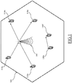
- Figure 1 is a schematic view of a cell 100 of a mobile communication network in which an embodiment of the present invention can be implemented.
- the cell 100 (schematically represented, for the sake of simplicity, by a hexagonal area in Figure 1 ) is a portion of a coverage area of the mobile communication network in which one or more radio transceivers (not shown) of a radio communication station, such as an evolved Node B, or eNodeB 105 in 3GPP Long Term Evolution (LTE)/LTE Advanced (LTE-A) systems, manage communications (i.e., transmission and/or reception of information, such as binary data packets) of user equipment or UE (e.g., mobile telephones, smartphones and tablets), such as the six UE 110a, 110b, 110c, 110d, 110e and 110f within the cell 100 in the example of Figure 1 .
- the eNodeB 105 allocate communication resources, in terms of portions of an available communication transmission band (indicated as physical resource blocks - PRBs or RBs), for the communications of the UE 110a-f.
- UE 110a and UE 110b are assumed to be involved in an "infrastructure-based", or INFRA, communication with respective UE (not shown) outside the cell 100 through the eNodeB 105.
- the UE 110a transmits information (to be sent to a receiver UE outside the cell 100 ) to the eNodeB 105 via an uplink channel comprised in a portion of communication resources (uplink resources) generally allocated by the eNodeB 105 for receiving data from the UE 110a, 110b, 110c, 110d, 110e and 110f within the cell 100.
- uplink resources uplink resources
- the UE 110b receives information (sent by a transmitter UE outside the cell 100 ) from the eNodeB 105 via a downlink channel comprised in a portion of communication resources (downlink resources) generally allocated by the eNodeB 105 for providing data to the UE 110 within the cell 100.
- the UE 110c and the UE 110d are assumed to be involved in an INFRA communication with one another through the eNodeB 105.
- the UE 110c transmits information (i.e., in the form of data packets) via an uplink channel to the eNodeB 105, while the UE 110d receives such information (i.e., again in the form of data packets) via a downlink channel from the eNodeB 105.
- the UE 110e and the UE 110f are assumed to be involved in a Device-to-Device, or D2D, communication (i.e., UE 110e and UE 110f exchange information directly, without having to pass through the eNodeB 105 ).
- the UE 110e and the UE 110f may transmit/receive information to/from the other via either an uplink or downlink channel (as described in greater detail in the following).
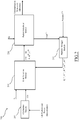
- FIG. 2 it is a schematic block diagram of a portion of a communication system 200 according to an embodiment of the present invention for managing communication in the cell 1 00.
- the communication system 200 is adapted to manage the selection between communication types (i.e., INFRA communication or D2D communication) and the allocation of communication resources (e.g., by means of a scheduling of communication data packets over resource blocks) for all the communication of the UE 110a-f in the cell 100.
- communication types i.e., INFRA communication or D2D communication
- allocation of communication resources e.g., by means of a scheduling of communication data packets over resource blocks
- the communication system 200 comprises a conflict graph (CG) builder module 205 that may be a module/function located in an eNodeB of the mobile communication network such as the eNodeB 105 in the cell 100 and configured to compute a conflict graph CG based on positions and transmission powers of all the UE 110 inside the cell 100.
- CG conflict graph
- the transmission powers of all the UE 110a-f inside the cell 100 are known to, and provided by, the eNodeB 105, while the position of the UE 110a-f may be obtained by means of a known positioning technique (e.g., using GPS signals, network signals or a combination thereof).
- the conflict graph CG is a graph where a communication (already active or to be established) between any two UE, such as the UE 110c and 110d, and the UE 110e and 110f in the example of Figure 1 , is indicated as a graph node, and a graph edge connecting two nodes denotes a conflict between the corresponding communications (i.e., such communications provoke reciprocal interferences).
- An edge between two graph nodes implies that a separate allocation of resources is required for preventing a conflict between the two communications represented by such nodes.
- the communication system 200 also comprises a statistic manager module 210 that may be a module/function located in an eNodeB of the mobile communication network such as the eNodeB 105 in the cell 100 and configured to provide indications regarding available communication rates, or simply rates (e.g., expressed as bit per second bps), for INFRA and D2D communications and amounts of available downlink/uplink resources (i.e., resources available for downlink/uplink channels) for INFRA and D2D communications based upon information Load D / U about downlink/uplink communication resources actually allocated and usage metrics Statistics D / U of the downlink/uplink communication resources (i.e., statistics data regarding ongoing communication managed by the communication system, for example obtained from the Channel Quality Indication provided by the UE 110a-f to the eNodeB 105 ) thereof under the viewpoint of both downlink and uplink channels.
- the statistic manager module 210 provides indications regarding:
- the statistic manager module 210 provides indications regarding:
- the rate R i D 2 ⁇ D is the rate that the communication c i would have if performed as a D2D communication; it should be noted that the rate R i D 2 ⁇ D is equal to zero if the UE involved in the communication c i are beyond a D2D range within which such UE are capable of performing a D2D communication.
- the rates R i UL and R i DL are the rates (for the uplink channel and the downlink channel, respectively) that the communication c i would have if performed as an INFRA communication.
- the communication system 200 comprises a link selection module 215, which is configured and operable to select the communication type (i.e., D2D or INFRA communication) between two (or more) UEs 105.
- the link selection module 215 may be a module/function located in an eNodeB of the mobile communication network such as the eNodeB 105 in the cell 100.
- the link selection module 215 is coupled with the CG builder module 205 for receiving the conflict graph as an input.
- the link selection module 215 is coupled with the statistic manager module 210 for receiving therefrom the aforementioned indications M DL , M UL , R i D 2 ⁇ D , R i UL , and R i DL as inputs.
- the link selection module 215 receives a requested rate A i for the considered communication c i , as a further input; such requested rate A i may be provided by the Evolved Packet Core (EPC - not detailed in Figure 2 ) of the communication system 200 according to a communication traffic in the mobile telecommunication network.
- EPC Evolved Packet Core
- the link selection module 215 selects whether to establish, or switch to if already active, the communication c i as an INFRA communication or as a D2D communication on the basis of the received inputs (as described in the following).
- the link selection module 215 provides as output a communication command which determines whether the communication c i has to be established as, or switched to if already active, an INFRA communication or a D2D communication.
- a single binary variable is provided that defines if the D2D communication is to be established via downlink or uplink - e.g., the single binary variable set to 1 corresponds to uplink, while the single binary variable set to 0 corresponds to downlink.
- the link selection module 215 further provides as output also a modified conflict graph ( CG '), corresponding to the conflict graph CG modified in order to take into account the communication command (e.g., if a communication c i of the D2D-type was interfering with other communications, by switching such communication c i from D2D communication to INFRA communication the edge in the CG is deleted, since the LTE/LTE-A standard already guarantees that communication resource sharing between UE performing INFRA communication is avoided according to).
- CG ' modified conflict graph
- the link selection module 215 further provides as output also a restrictions command RS .
- the restrictions command RS comprises a set of restrictions regarding the communication resources in use within the cell 100.
- the restrictions command RS is provided in the format ⁇ [UE_group],[PRBs] ⁇ , where UE_group denote (e.g., lists) any set of UE (e.g., UE performing D2D communication, UE exploiting uplink and/or downlink channels, UE located along cell edges etc. ) and PRBs denote the resources that should be associated with that set of UE (e.g., communication resources that are reserved for the corresponding UE listed in the UE_group, as described in the following).
- the communication system 200 also comprises a packet scheduler module 220, configured to allocate communication resources on the basis of the outputs of the link selection module 215 (as described in the following).
- the packet scheduler module 220 is coupled with the link selection module 215 for receiving as inputs the outputs of the link selection module 215.
- the packet scheduler module 220 may be a module/function located in an eNodeB of the mobile communication network such as the eNodeB 105 in the cell 100
- the packet scheduler module 220 receives as an input an indication Q i regarding the amount of data to be transmitted during the communication c i .
- the indication Q i is directly provided to the packet scheduler module by the eNodeB 105, which manages the amount of data, transmitted through downlink channels and knows the amount of data transmitted through uplink channels from Buffer Status Reports (BSR) provided by the UE 110a-f within the cell 100.
- BSR Buffer Status Reports
- the packet scheduler module 220 performs the allocation of the communication resources for each communication c i within the memory cell 100.
- the packet scheduler module 220 schedules in which resource block each data packet belonging to the communication c i has to be exchanged (i.e., transmitted and/or received); therefore, the allocation of communication resources is often indicated as packet scheduling.
- Such a packet scheduling is then provided to the UE 110a-f within the cell 100, which then communicate accordingly.
- the packet scheduler module 220 outputs the information about actually allocated communication resources Load D / U that are provided to the statistic manager module 210.
- the link selection module 215, the packet scheduler module 220 and the statistic manager module 210 form a feedback loop that allows increasing the efficiency of the operation of selection and the packet scheduling of each communication c i on the basis of the actually allocated communication resources Load D / U and on the basis of the usage metrics Statistics D / U (i.e., an actual state and past states of the mobile communication network).
- the CG builder module 205, the statistic module 210 and the link selection module 215 provide their outputs with a link selection period TLS greater than a Transmission Time Interval or TTI (which is the duration of a transmission of a data packet over uplink or downlink channels) since the selection between INFRA communication and the D2D communication, particularly in case of a switching of communication type involve a certain overhead time, and it would be computationally hard performing it with a TTI periodicity.
- TTI Transmission Time Interval
- the link selection module 215 operating with a periodicity equal to the link selection period TLS, longer than a Transmission Time Interval TTI, a frequent switching between INFRA and D2D types for an ongoing communication is avoided; such a frequent switching between INFRA and D2D communication types would be detrimental for such ongoing communication.
- fragments e.g., one or more data packets
- fragments of the ongoing communication would be sent to the eNodeB during INFRA-type communication
- fragments of the ongoing communication would be sent to the receiver UE during D2D-type communication; therefore, part of the fragments of the ongoing communication would be unattainable by the eNodeB and/or by the receiver UE, thereby requiring a retransmission of such fragments to one between the eNodeB (for INFRA-type communication) or to the receiver UE (for the D2D-type communication) in order to allow a correct reassembly of the ongoing communication (consequently lowering a quality of the communication and increasing the workload for the mobile communication network).
- the link selection period TLS has a duration of the order of one hundred of millisecond, greater than a TTI (which has a duration of 1ms in LTE/LTE-A).
- the packet scheduler module 220 provides its outputs with a periodicity equal to one TTI, which allows the eNodeB 105 properly managing each communication c i in the memory cell 100 in real time (i.e., without causing delays in the communication c i ).
- the link selection module 215 determines which, between D2D communication and INFRA communication, is better for two UE, such as the UE 110c and 110d, and the UE 110e and 110f within the cell 100, according to a criterion aimed at optimizing one (or more) parameter of interest of the communication (e.g., a throughput).
- the link selection module 215 also determines on which channel (i.e., downlink or uplink channel) allocate the D2D communications according to the same criterion.
- the link selection module 215 is aware of:
- the link selection module 215 is aware of any possibly conflicting communications within the cell 100.
- the link selection module 215 performs the selection of the communication type not only by evaluating the available communication resources (or channel condition) but also evaluating separately the available downlink and uplink resources, or space (conversely, should only the channel condition be considered, then a D2D communication could be switched to an INFRA communication also in case of no available downlink resources).
- the link selection module 215 selects the communication type by solving an optimization problem.
- an objective function of such an optimization problem may be expressed as: max ⁇ i ⁇ I x i D 2 ⁇ D ⁇ UL ⁇ R i D 2 ⁇ D + x i D 2 ⁇ D ⁇ DL ⁇ R i D 2 ⁇ D + x i UL ⁇ min R i UL R i DL , wherein the variables x i D 2 ⁇ D ⁇ UL , x i D 2 ⁇ D ⁇ DL e x i UL ⁇ R + represent an allocated communication resource to the communication c i performed as a D2D communication on the uplink channel, as a D2D communication on the downlink channel and as an INFRA communication, respectively.
- the objective function (1) is solved according to the following constraints: d i ⁇ d i DL ; d i ⁇ d i UL , inequalities (2) and (3) define that a generic communication c i is performed as D2D communication (either on downlink channel or on uplink channel) only if the first binary variable is equal to one; d i UL + d i DL ⁇ 1 , inequality (4) defines that only one between the downlink channel and the uplink channel may be selected for the communication c i of the D2D-type; n D 2 ⁇ D ⁇ DL + ⁇ i ⁇ I x i UL ⁇ R i UL R i DL ⁇ M DL , where n D2D-DL ( ⁇ R + ) represents the communication resources allocable for performing D2D communication on the downlink channel, ⁇ i ⁇ I x i UL ⁇ R i UL R i DL represents the communication resources allocable for
- the packet scheduler module 220 preferably comprises two scheduler branches (not shown in Figure 2 ) each of which managing the allocation of a respective part of the communication resources. Namely, an uplink scheduler branch is dedicated to uplink resources allocation and a downlink scheduler branch dedicated to downlink resources allocation.
- Each scheduler branch allocates the respective uplink/downlink resources by applying a predetermined allocation scheme, such as for example the Maximum Carrier-to-Interference Ratio (MaxC/I) scheduling, the Round Robin (RR) scheduling, or the Proportionally Fair (PF) scheduling, combined with the outputs d i , d i UL , d i DL , RS and CG' provided by the link selection module 215 at each link selection period TLS and combined with the indication Q i (regarding the amount of data to be transmitted) received at each TTI.
- a predetermined allocation scheme such as for example the Maximum Carrier-to-Interference Ratio (MaxC/I) scheduling, the Round Robin (RR) scheduling, or the Proportionally Fair (PF) scheduling
- the scheduler branches may share the same downlink/uplink resources between UE 110a, 110b, 110c and 110d involved in INFRA communications and UE 110e and 110f involved in D2D communication that do not interfere with each others (while downlink/uplink resource sharing between UE 110a, 110b, 110c and 110d involved in INFRA communication is avoided according to LTE/LTE-A standard).
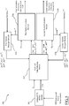
- FIG. 3 it is a schematic flowchart of a resource allocation operation according to an embodiment of the present invention for the communication system 200.
- the packet scheduler module 220 receives an input list L1 of all the I communications c i taking place in the cell 100 in the next TTI, then at step (decision block) 310 the packet scheduler module 220 checks whether it is possible to allocate mutually exclusive resources to all the I communications c i taking place in the cell 100. In the affirmative case (exit branch Y of decision block 310 ), such allocation of mutually exclusive resources is done at step 315; the allocation of mutually exclusive resources ensures the maximum throughput and the minimum interference attainable between the I communications c i and, and the operation ends at step 320.
- step 325 ordered list L2 of the I communications c i taking place in the cell 100 is generated by the packet scheduler module 220.
- the ordering of the ordered list L2 may be implemented according to any suitable allocation schemes (e.g., MaxC/I, PF or RR scheduling mentioned above).
- the packet scheduler module 220 allocates the communication resources to any communication c i taking into account the communication type indicated in the binary data d i and d i UL , d i DL , the modified conflict graph CG' and the restrictions command RS.
- step (decision block) 335 the packet scheduler module 220 verifies if there are communication resources available for allocation. In the negative case (exit branch N of decision block 335 ), the allocation operation ends at step 320.
- the packet scheduler module 220 at step (decision block) 340 verifies if the end of the ordered list L2 of the I communications c i taking place in the cell 100 has been reached.
- the packet scheduler module 220 at step 345 extracts the next communication c i + 1 from the ordered list L2 and the operations return at step 330, for allocating communication resources to the next communication c i + 1 .
- the packet scheduler module 220 repeats the above operations for the subsequent TTIs.
- the inputs d i , d i UL , d i DL , RS and CG' do not change.
- the inputs d i , d i UL , d i DL , RS and CG' to the packet scheduler module 220 may change.
- the communication system may be configured to handle D2D communications also between two UEs located in different cells.
- FIG 4 it is a schematic view of a pair of cells 400a e 400b of a mobile communication network in which an embodiment of the present invention may be implemented.
- the two cells are assumed to be adjacent cells, but the solution is not limited to pairs of adjacent cells (e.g., in the case of small cells).
- communications within a first cell 400a of the pair of adjacent cells 400a are managed by a first eNodeB 405a, while communications within the second cell 400b of the pair of adjacent cells 400a are managed by a second eNodeB 405b.
- Two UE namely a first UE 410a, within the first cell 400a, and a second UE 410b, within the second cell 400b, are involved in an inter-cell D2D communication.
- a third UE 410c within the second cell 400b may cause interference to the inter-cell D2D communication between UE 410a and 410b and, viceversa, UE 410a and 410b in D2D communication may cause interference to a communication performed by the third UE 410c.
- inter-cell D2D communications are managed over a selected group of cells of the mobile communication network , e.g. a selected group of cells may comprise a central cell and all the adjacent cells (i.e., generally 6 cells) adjacent to the central cell.
- FIG. 5 it is a schematic block diagram of a communication system 500 according to an embodiment of the present invention for managing communications in a plurality of cells of the mobile communication networks, such as the cells 400a and 400b.
- the communication system 500 comprises an enlarged CG builder module 505 adapted to provide an enlarged conflict graph CGe based on the position of the users inside adjacent cells, such as the first cell 400a and the second cell 400b in the example of Figure 4 , and their respective transmission powers.
- the enlarged CG builder module 505 receives UE position and transmission power information from all the cells in the mobile communication network or from the selected group of cells (e.g., seven cells of which one cell is a central cell of the group and the remaining six cells are adjacent to the central cell) of the mobile communication network.
- the selected group of cells e.g., seven cells of which one cell is a central cell of the group and the remaining six cells are adjacent to the central cell
- the enlarged CG builder module 505 may be a module/function part of the Evolved Packet Core (EPC - not shown) of the communication system 500 connected to all the eNodeBs of the mobile communication network, or may be a module/function comprised in an eNodeB, such as the eNodeB 400a or 400b of the example of Figure 4 , of the selected group of cells of the mobile communication network mentioned above.
- EPC Evolved Packet Core
- a multi-cell link selection module 515 is provided to perform the selection of the communication type for the UE 405a, 405b and 405c, comprised in adjacent cells, i.e. the cells 400a and 400b in the example of Figure 4 .
- the multi-cell link selection module 515 receives UE position transmission power information from all the cells in the mobile communication network.
- the multi-cell link selection module 515 may be comprised in an Evolved Packet Core (EPC - not shown) of the communication system 500 connected to all the eNodeBs of the mobile communication network, or may be a module/function comprised in an eNodeB, such as the eNodeB 400a or 400b of the example of Figure 4 , of the selected group of cells of the mobile communication network mentioned above.
- EPC Evolved Packet Core
- the communication system 500 comprises a packet scheduler module for managing the allocation of communication resources and a statistics manager module for providing indications about amounts of available communication resources and rates in each respective cell of the mobile communication network.
- the communication system comprises a first packet scheduler module 520a for managing the allocation of communication resources in the first cell 400a and a first statistics manager module 510a for providing indications about amounts of available communication resources MA DL and MA UL , and rates RA i D 2 ⁇ D , RA i UL , and RA i DL based on communication resources actually allocated Load A D / U (provided by the first packet scheduler module 520a to which is coupled) and usage metrics Statistics A D / U of the communication resources for the first cell 400a.
- the communication system 500 comprises a second packet scheduler module 520b for managing the allocation of communication resources in the second cell 400b and a second statistics manager module 510b for providing indications about amounts of available communication resources MB DL and MB UL , and rates RB i D 2 ⁇ D , RB i UL , and RB i DL based on communication resources actually allocated Load B D / U (provided by the second packet scheduler module 520b to which is coupled) and usage metrics Statistics B D / U of the communication resources for the second cell 400b.
- the multi-cell link selection module 515 is coupled with the enlarged CG builder module 505 for receiving the enlarged conflict graph CGe as an input.
- the multi-cell link selection module 515 is coupled with the first statistic manager module 510a for receiving corresponding indications MA DL , MA UL , RA i D 2 ⁇ D , RA i UL a, and RA i DL (referred to the first cell 400a) as inputs.
- multi-cell link selection module 515 is coupled with the second statistic manager module 510b for receiving corresponding indications MB DL , MB UL , RB i D 2 ⁇ D , RB i UL , and RB i DL (referred to the second cell 400b) as inputs. Finally, the multi-cell link selection module 515 receives a requested rate A i for the communication c i , as a further input.
- the multi-cell link selection module 515 selects whether to establish the communication c i as an INFRA communication or as a D2D communication based on the received inputs (similarly as described above) for the UE 410a, 410b and 410c in both the cells 400a and 400b.
- the multi-cell link selection module 515 is connected to both the first packet scheduler module 520a and the second packet scheduler module 520b for providing them a respective communication command which determines whether the communication c i has to be established as, or switched to if already active, an INFRA communication or a D2D communication.
- the communication command for the first packet scheduler module 520a comprises a first binary variable dA i (e.g., a bit) that defines if the communication c i is an INFRA or D2D communication in the first cell 400a and, if the D2D communication is selected, a second binary variable dA i UL and a third binary variable dA i DL that defines if the D2D communication has to be established via downlink or uplink channels in the first cell 400a.
- dA i e.g., a bit
- the communication command for the second packet scheduler module 520b comprises a fourth binary variable dB i (e.g., a bit) that defines if the communication c i is an INFRA or D2D communication in the second cell 400b and, if the D2D communication is selected, a fifth binary variable dB i UL and a sixth binary variable dA i DL that defines if the D2D communication has to be established via downlink or uplink channels in the second cell 400b.
- dB i e.g., a bit
- the link selection module 515 selecting the INFRA-type for a communication c i will provide a communication command referred to such communication c i only for the cell 405a or 405b in which there is/are the UE that perform (or will perform) such communication c i .
- the multi-cell link selection module 515 also provides to both the first packet scheduler module 520a and the second packet scheduler module 520b a modified enlarged conflict Graph ( CGe' ) modified in order to take into account the communication commands provided.
- CGe' modified enlarged conflict Graph
- the multi-cell link selection module 515 provides as output also a first restrictions command RS A and a second restrictions command RS B to the first packet scheduler module 520a and the second packet scheduler module 520b, respectively.
- each one of the restrictions commands RS A and RS B comprises a set of restrictions regarding the communication resources to be allocated to a UE_group listing UE, such as he UE 410a, 410b and 410c, near boundaries (e.g., within an interference region 420 described below) of two (or more) adjacent cells, such as the first cell 400a and the second cell 405b .
- the enlarged CG builder module 505, the statistic modules 510a and 510b and the multi-cell link selection module 515 provide their outputs with a link selection period TLS greater than a TTI as explained above with reference to the single-cell scenario of Figure 1 .
- the link selection period TLS has a duration in the order of hundred of milliseconds, greater than a TTI (1ms) in LTE/LTE-A.
- the packet scheduler modules 520a and 520b provides their outputs with a periodicity equal to the TTI, as explained above with reference to the single-cell scenario of Figure 1 .
- a scenario for the communication system 500 is the management of a D2D communication between the two UE 410a and 410b within two adjacent cells 400a and 400b and served by different eNodeBs 405a and 405b, respectively (as shown in Figure 4 ).
- the communication system 500 coordinates the allocation of communication resources between the two cells 400a and 400b in order to reduce possible interference between the UE 410a, 410b and 410c (and any other UE within the cells 400a and 400b, not shown).
- the coordination of communication resources allocation is performed by the multi-cell link selection module 515 by coordinating the operation of the two packet scheduler modules 520a and 520b, thus with a periodicity equal to the link selection period TLS.
- the first UE 410a within the first cell 400a is transmitting to the second UE 410b within the second cell 405b by performing a D2D communication c ab .
- the third UE 410c within the second cell 400b is one of the possible interferer to D2D communication c ab , particularly for the second UE 410b (under the assumption that a sharing of communication resources between D2D communications and INFRA communications is allowed in the second cell 400b ).
- the dashed circle enclosing the second UE 410b and the third UE 410c represents an "interference radius" 415 of the third UE 410c. Within such interference radius, INFRA communications c int performed by the third UE 410c may interfere with communication c ab performed between the first and the second UE 410a and 410b.
- the communication system 500 in order to reduce interferences is configured to allocate every possible interfering communication c int (i.e., a node connected by an edge to the node representing the D2D communication c ab in the enlarged conflict graph CGe ) on communication resources different from the communication resources allocated to the D2D communication c ab .
- every possible interfering communication c int i.e., a node connected by an edge to the node representing the D2D communication c ab in the enlarged conflict graph CGe
- an "interference region" 420 (represented in Figure 4 by a solid black rectangle) is defined as the region in which D2D communications between UE of different cells, such as the UE 410a and 410b, may experience interferences due to other UE within the interference region 420 that performs INFRA communications, such as in case of the third UE 410c in the second cell 400b, and viceversa INFRA communications may experience interferences due to D2D communications.
- the interference region 420 extends over both the cells 400a and 400b and thus comprises a first cell 400a portion 420 A and a first cell 400a portion 420 B .
- the multi-cell link selection module 515 determines any possible interfering communication c int from the analysis of the modified enlarged conflict graph CGe' provided by the enlarged CG builder module 505 and provides the restrictions commands RS A and RS B both comprising UE_group listing sets of UE, such as the UE 405a, 405b and 405c comprised within the interference region 420 and PRBs indicating communication resources to be allocated to the UE of the UE_group in a non-interfering way within the interference region 420.
- the packet scheduler modules 520a and 520b allocate the D2D communication c ab and the INFRA communication c int according to the restrictions commands RS A and RS B .
- the packet scheduler modules 520a and 520b may allocate the communication resources PRB A and PRB B for the D2D communication c ab and the INFRA communication c int , respectively, having a maximum possible distance (in frequency) one with respect to the other.
- the first packet scheduler module 520a allocates communication resources for the first UE 410a, which transmits data packets to the second UE 410b from within the portion 420 A of the interference region 420, on communication resources PRB A 605 located in an initial portion of the transmission band 610 available for the communications in the first cell 405a.
- the second packet scheduler module 520b allocates communication resources for the third UE 410c, which transmits data packets from within the portion 420 B of the interference region 420, on communication resources PRB B 615 located in a final portion of the transmission band 620 available for the communications in the first cell 405a.
- a global packet scheduler module may be provided for managing the allocation of resources of UE in all the cells of the mobile communication network or for managing a selected group of cells thereof.
- the embodiments of the present invention herein described may manage efficiently communications resources allocation in order to improve the operation of the mobile communication network taking advantages introduced by the availability of D2D communication (e.g., cell offloading and reduction of used spectrum, and a lower latency with respect to the INFRA communication), without incurring in the drawbacks associated with the coexistence of D2D communications and INFRA communications (e.g., interferences between D2D communications and INFRA communications and D2D communications not controlled by the communication system).
- D2D communication e.g., cell offloading and reduction of used spectrum, and a lower latency with respect to the INFRA communication
Description
- The present invention refers to communication systems. More particularly, the present invention relates to the field of wireless or mobile telecommunication networks. Even more particularly, the present invention relates to a resource allocation system and method adapted to implement Device-to-Device communications in wireless communication networks.
- Generally, in a mobile (cellular) telecommunication network, communications among mobile communication devices (e.g., mobile telephones, smartphones and tablets) - generally referred to as User Equipment, or UE in brief - pass through the telecommunication network: two UE, connected to respective "serving" radio transceivers of the network (e.g., radio transceivers of a same or different eNodeB - evolved Node B - in the 3GPP Long Term Evolution (LTE)/LTE Advanced (LTE-A) systems), communicate with each other by means of physical communication channel(s) that are set-up and terminated between the radio transceivers and the UE.
- As an alternative to such traditional "2-hop" communication, which hereinafter will be also referred to as "infrastructure-based", or INFRA, communication, recently UE have been made available that are also capable of communicating directly among them when they happen to be within a relatively short range.
- This direct radio communication among UE is commonly referred to as "Device-to-Device", or D2D, communication and is based on D2D communication links directly established by two (or more) UE. D2D communication differs from the traditional INFRA communication in that the information is exchanged through physical communication channels that are set-up and terminated between the UE directly, without passing through the network.
- The D2D communication links between UE communicating directly among them are generally established over frequencies comprised in a communication frequency range used in the INFRA communications. Thus, non-negligible interference may be experienced by UE performing INFRA communications in the proximities of UEs performing D2D communications and, particularly, when the UEs perform communications over the same and/or neighboring frequencies used for D2D communications, and, vice-versa UEs performing D2D communications may experience interference due to nearby UEs performing INFRA communications over the same or neighboring frequencies. This mutual interference experienced by UE performing INFRA communications and UE performing D2D communications causes an overall degradation of both the INFRA and D2D communications.
- Therefore, communication (radio) resources, such as physical resource elements comprised in Physical Resource Blocks - PRBs or RBs - in the LTE/LTE-A systems, have to be carefully allocated among UEs performing INFRA communication and D2D communication in order to achieve satisfying network operation performance (e.g., in terms of Quality of Service or QoS, network capacity, energy efficiency, throughput, etc.).
- In the art some expedients for the selection between INFRA or D2D communications and the communication resources allocation thereof have been proposed.
- For example, Doppler, Yu, Ribeiro, Janis, "Mode selection for Device-to-Device Communication underlaying an LTE-Advanced Network", Wireless Communications and Networking Conference (WCNC), 2010 IEEE, 18-21 April 2010, discloses a mode selection scheme for selecting between INFRA or D2D communications according to respective achievable throughputs.
- Chien, Chen, Hsieh, "Exploiting Spatial Reuse Gain through Joint Mode Selection and Resource Allocation for Underlay Device-to-Device Communications" 15th International Symposium on Wireless Personal Multimedia Communications (WPMC), 24-27 Sept. 2012, discloses both a mode selection and a communication resources allocation scheme.
- Mohammad Zulhasnine, Changcheng Huang, Anand Srinivasan, "Efficient Resource Allocation for Device-to-Device Communication Underlaying LTE Network", 6th International Conference on Wireless and Mobile Computing, Networking and Communications (WiMob), 11-13 Oct. 2010 discloses a Mixed Integer Non linear Program (MINLP) for resource allocation and a greedy heuristics for solve the problem at a Transmission Time Interval, or TTI, timescale.
- Zhang, Cheng, Yang, Jiao, "Interference-Aware Graph Based Resource Sharing for Device-to-Device Communications Underlaying Cellular Networks", Wireless Communications and Networking Conference (WCNC), 2013 IEEE, 7-10 April 2013 discloses an interference-aware graph based resource sharing algorithm form allocating resources to INFRA and D2D communications in the coverage area of a single cell.
-
WO 2013/008167 discloses methods, apparatus and computer program products that facilitate scheduling in a hybrid communication network with varying types of devices, such as D2D mobile terminals and other, such as cellular, mobile terminals. In this regard, a D2D scheduling activity factor is calculated by a network node based at least in part on a total number of both D2D mobile terminals and other mobile terminals, and the scheduling activity factor is sent to at least one D2D mobile terminal. The D2D mobile terminal uses the scheduling activity factor to determine when to transmit locally measured signal to interference plus noise ratio (SINR) information to a network node. The D2D mobile terminal may be scheduled by the network node separately from other mobile terminals based at least in part on the SINR information.. -
US 2013/0322413 discloses a method for the use in a first Wireless Transmit/Receive Unit (WTRU) including transmitting a request for D2D communication resources to an enhanced Node B. The first WTRU may receive an allocation of resources for multiple TTI to be used for D2D communications from the enhanced Node B. The first WTRU may schedule D2D communications with a second WTRU to be performed during the allocated resources. The first WTRU may perform D2D communications with the second WTRU using half duplex communications during the allocated resources. -
US 2010/0261469 discloses a method that comprises measuring a first link quality of a first link based at least in part on a first power value; measuring a second link quality of a second link based at least in part on a second power value; and determining a suitable D2D mode for a D2D connection based at least in part on the first link quality, the second link quality, and one or more D2D UE constraints. - Wen, Zhu, Wang, "QoS-Aware mode selection and resource allocation scheme for device-to-device (D2D) communication in cellular networks", IEEE International Conference on Communications Workshops (ICC), 2013 9-13 June 2013, discloses a QoS-Aware mode selection and uplink communication resource allocation.
- The Applicant has found that the known solutions mentioned above fail in providing a satisfactory framework for selecting between D2D and INFRA communications and for allocating the communication resources thereof.
- Therefore, the Applicant has coped with the problem of devising a system and method adapted to select between D2D and INFRA communications whichever provides the best communication efficiency (according to one or more communication parameters, such as for example a throughput) for every communicating UE and, at the same time, also adapted to provide an allocation of communication resources in order to obtain best network operation performance according to available communication resources (avoiding interferences among UE regardless of whether they are communicating through INFRA or D2D communication within the mobile communication network).
- Particularly, one aspect of the present invention proposes a method for allocating communication resources for communications performed by user equipment in a mobile communication network is proposed. The method comprises the following steps. Receiving a first indication about an amount of available communication resources; obtaining information about interfering communications between user equipment; for each communication between user equipment to which communication resources have to be allocated: receiving a second indication about an available communication rate for an infrastructure-based communication and for a device-to-device communication; receiving a third indication about a requested communication rate for said each communication; making a selection between an infrastructure-based communication type or a device-to-device communication type based on the first, second and third indications and the information about interfering communications, and allocating communication resources to each communication on the basis of the selection between an infrastructure-based communication type or a device-to-device communication type.
- Preferred features of the present invention are set forth in the dependent claims.
- In the present invention the steps of receiving a first indication about an amount of available communication resources; obtaining information about interfering communications between user equipment; receiving a second indication about an available communication rate for an infrastructure-based communication and for a device-to-device communication; receiving a third indication about a requested communication rate for said each communication, and making a selection between an infrastructure-based communication type or a device-to-device communication, are performed with a periodicity longer than a periodicity at which the step of allocating communication resources to each communication on the basis of the selection is performed.
- In one embodiment of the invention, each communication comprises a plurality of data packets and the periodicity of the step of allocating communication resources to each communication on the basis of the selection corresponds to a duration of a transmission in the mobile communication network.
- In one embodiment of the invention, said obtaining information about interfering communications is based on information on position and power measurements of the user equipment within the mobile communication network.
- In one embodiment of the invention said obtaining information about interfering communications comprises building a conflict graph based on information on position and power measurements of the user equipment within the mobile communication network, the conflict graph indicating interference between couples of communicating user equipment.
- In one embodiment of the invention the method further comprises generating a modified conflict graph by modifying the conflict graph on the basis of said selection between an infrastructure-based communication type or a device-to-device communication type.
- In one embodiment of the invention, said allocating communication resources is further based on said modified conflict graph.
- In one embodiment of the invention, the first indication and the second indication are based on usage metrics of the communication resources regarding ongoing communications.
- In one embodiment of the invention, the first indication and the second indication are further based on information about communication resources actually allocated by the step of allocating communication resources.
- In one embodiment of the invention, the mobile communication network comprises a plurality of cells which are portions of a coverage area of the mobile communication network, and wherein the method is configured for allocating communication resources for communications performed by user equipment within a selected group of cells.
- In one embodiment of the invention, the method further comprises, for each adjacent cells of said selected group of cells, defining an interference region, comprising a portion of each adjacent cell of said group of cells, in which device-to-device communications between user equipment of different cells may experience interferences due to other user equipment within the interference region that perform infrastructure-based communications and viceversa infrastructure-based communications may experience interferences due to device-to-device communications.
- In one embodiment of the invention, the method further comprises generating a list of user equipment comprised within the interference region, and indicating communication resources to be allocated to the user equipment of the list in a non-interfering way within the interference region.
- Another aspect of the present invention proposes a mobile communication network for managing communication of user equipment. The mobile communication network comprising a coverage area divided into a plurality of cells, each cell being provided with a radio communication station for managing communications of user equipment the cell. The mobile communication network further comprises a communication system configured for implementing the method mentioned above.
- In on embodiment of the invention, the communication system comprises at least one link selection module configured for making said selection between an infrastructure-based communication type or a device-to-device communication, and at least one scheduler module configured for performing said allocating communication resources to each communication, the at least one link selection module being coupled with the at least one scheduler module for allocating communication resources according to said selection.
- In one embodiment of the invention, at least one link selection module comprises a link selection module configured for making said selection between an infrastructure-based communication type or a device-to-device communication for communications taking place in a selected group of cells of the mobile communication network, and wherein the at least one scheduler module comprises a plurality of scheduler modules each scheduler module being configured for performing said allocating communication resources to each communication in a respective cell of the mobile communication network.
- These and others features and advantages of the solution according to the present invention will be better understood by reading the following detailed description of an embodiment thereof, provided merely by way of non-limitative example, to be read in conjunction with the attached drawings, wherein:
-
Figure 1 is a schematic view of a cell of a mobile communication network in which an embodiment of the present invention can be implemented; -
Figure 2 is a schematic block diagram of a portion of a communication system according to an embodiment of the present invention for managing communication in the cell ofFigure 1 ; -
Figure 3 is a schematic flowchart of a resource allocation operation according to an embodiment of the present invention for the communication system ofFigure 2 ; -
Figure 4 is a schematic view of a pair of adjacent cells of a mobile communication network in which an embodiment of the present invention can be implemented; -
Figure 5 is a schematic block diagram of a communication system according to an embodiment of the present invention for managing communications in a plurality of cells of the mobile communication networks, such as in the cells ofFigure 4 , and -
Figure 6 is a schematic representation of a resources allocation scheme for avoiding interference according to an embodiment of the present invention that can be implemented by the communication system ofFigure 5 . - With reference to the figures,
Figure 1 is a schematic view of acell 100 of a mobile communication network in which an embodiment of the present invention can be implemented. - The cell 100 (schematically represented, for the sake of simplicity, by a hexagonal area in
Figure 1 ) is a portion of a coverage area of the mobile communication network in which one or more radio transceivers (not shown) of a radio communication station, such as an evolved Node B, or eNodeB 105 in 3GPP Long Term Evolution (LTE)/LTE Advanced (LTE-A) systems, manage communications (i.e., transmission and/or reception of information, such as binary data packets) of user equipment or UE (e.g., mobile telephones, smartphones and tablets), such as the six UE 110a, 110b, 110c, 110d, 110e and 110f within thecell 100 in the example ofFigure 1 . For example, the eNodeB 105, allocate communication resources, in terms of portions of an available communication transmission band (indicated as physical resource blocks - PRBs or RBs), for the communications of the UE 110a-f. - Several communications may take place at once within the
cell 100. - In the example of
Figure 1 , UE 110a and UE 110b are assumed to be involved in an "infrastructure-based", or INFRA, communication with respective UE (not shown) outside thecell 100 through theeNodeB 105. The UE 110a transmits information (to be sent to a receiver UE outside the cell 100) to the eNodeB 105 via an uplink channel comprised in a portion of communication resources (uplink resources) generally allocated by the eNodeB 105 for receiving data from the UE 110a, 110b, 110c, 110d, 110e and 110f within thecell 100. Conversely, theUE 110b receives information (sent by a transmitter UE outside the cell 100) from theeNodeB 105 via a downlink channel comprised in a portion of communication resources (downlink resources) generally allocated by theeNodeB 105 for providing data to the UE 110 within thecell 100. - In the example of
Figure 1 , theUE 110c and theUE 110d are assumed to be involved in an INFRA communication with one another through theeNodeB 105. TheUE 110c transmits information (i.e., in the form of data packets) via an uplink channel to theeNodeB 105, while theUE 110d receives such information (i.e., again in the form of data packets) via a downlink channel from theeNodeB 105. - In the example of
Figure 1 , theUE 110e and theUE 110f are assumed to be involved in a Device-to-Device, or D2D, communication (i.e.,UE 110e andUE 110f exchange information directly, without having to pass through the eNodeB 105). TheUE 110e and theUE 110f may transmit/receive information to/from the other via either an uplink or downlink channel (as described in greater detail in the following). - Turning now to
Figure 2 , it is a schematic block diagram of a portion of acommunication system 200 according to an embodiment of the present invention for managing communication in thecell 100. - The
communication system 200 is adapted to manage the selection between communication types (i.e., INFRA communication or D2D communication) and the allocation of communication resources (e.g., by means of a scheduling of communication data packets over resource blocks) for all the communication of theUE 110a-f in thecell 100. - The
communication system 200 comprises a conflict graph (CG)builder module 205 that may be a module/function located in an eNodeB of the mobile communication network such as theeNodeB 105 in thecell 100 and configured to compute a conflict graph CG based on positions and transmission powers of all the UE 110 inside thecell 100. For example, the transmission powers of all theUE 110a-f inside thecell 100 are known to, and provided by, theeNodeB 105, while the position of theUE 110a-f may be obtained by means of a known positioning technique (e.g., using GPS signals, network signals or a combination thereof). The conflict graph CG is a graph where a communication (already active or to be established) between any two UE, such as theUE UE Figure 1 , is indicated as a graph node, and a graph edge connecting two nodes denotes a conflict between the corresponding communications (i.e., such communications provoke reciprocal interferences). An edge between two graph nodes implies that a separate allocation of resources is required for preventing a conflict between the two communications represented by such nodes. - The
communication system 200 also comprises astatistic manager module 210 that may be a module/function located in an eNodeB of the mobile communication network such as theeNodeB 105 in thecell 100 and configured to provide indications regarding available communication rates, or simply rates (e.g., expressed as bit per second bps), for INFRA and D2D communications and amounts of available downlink/uplink resources (i.e., resources available for downlink/uplink channels) for INFRA and D2D communications based upon information Load D/U about downlink/uplink communication resources actually allocated and usage metrics Statistics D/U of the downlink/uplink communication resources (i.e., statistics data regarding ongoing communication managed by the communication system, for example obtained from the Channel Quality Indication provided by theUE 110a-f to the eNodeB 105) thereof under the viewpoint of both downlink and uplink channels. For example, thestatistic manager module 210 provides indications regarding: - an amount of available downlink resources (e.g., expressed in PRBs) MDL, and
- an amount of available uplink resources (e.g., expressed in PRBs) MUL .
- In addition, for each communication ci (e.g., 0 ≤ i ≤ I; with I being a positive integer) in the cell 100 (either a communication to be established or an already on-going communication), the
statistic manager module 210 provides indications regarding: - an available rate for a communication ci if it is a D2D communication

- an available uplink rate for a communication ci if it is a INFRA communication Ri UL, and
- an available downlink rate for the communication ci if it is the INFRA communication

- In other words, the rate


- In one embodiment of the present invention, the
communication system 200 comprises alink selection module 215, which is configured and operable to select the communication type (i.e., D2D or INFRA communication) between two (or more)UEs 105. For example, thelink selection module 215 may be a module/function located in an eNodeB of the mobile communication network such as theeNodeB 105 in thecell 100. Thelink selection module 215 is coupled with theCG builder module 205 for receiving the conflict graph as an input. Thelink selection module 215 is coupled with thestatistic manager module 210 for receiving therefrom the aforementioned indications MDL, MUL,

link selection module 215 receives a requested rate Ai for the considered communication ci , as a further input; such requested rate Ai may be provided by the Evolved Packet Core (EPC - not detailed inFigure 2 ) of thecommunication system 200 according to a communication traffic in the mobile telecommunication network. - The
link selection module 215 selects whether to establish, or switch to if already active, the communication ci as an INFRA communication or as a D2D communication on the basis of the received inputs (as described in the following). Thelink selection module 215 provides as output a communication command which determines whether the communication ci has to be established as, or switched to if already active, an INFRA communication or a D2D communication. In one embodiment of the invention, the communication command comprises a first binary variable di (e.g., one bit) that defines if the communication ci is an INFRA or D2D communication - e.g., di = 0 corresponds to INFRA communication, while di = 1 corresponds to D2D communication - and, if the D2D communication is selected (i.e., di = 1) a second binary variable di UL (e.g., one bit) that defines if the D2D communication is to be established via uplink - e.g., di UL = 1 corresponds to uplink selected, while di UL = 0 corresponds to uplink not selected - a third binary variable


- The
link selection module 215 further provides as output also a modified conflict graph (CG'), corresponding to the conflict graph CG modified in order to take into account the communication command (e.g., if a communication ci of the D2D-type was interfering with other communications, by switching such communication ci from D2D communication to INFRA communication the edge in the CG is deleted, since the LTE/LTE-A standard already guarantees that communication resource sharing between UE performing INFRA communication is avoided according to). - Preferably, the
link selection module 215 further provides as output also a restrictions command RS. For example, the restrictions command RS comprises a set of restrictions regarding the communication resources in use within thecell 100. In an embodiment of the present invention, the restrictions command RS is provided in the format {[UE_group],[PRBs]}, where UE_group denote (e.g., lists) any set of UE (e.g., UE performing D2D communication, UE exploiting uplink and/or downlink channels, UE located along cell edges etc.) and PRBs denote the resources that should be associated with that set of UE (e.g., communication resources that are reserved for the corresponding UE listed in the UE_group, as described in the following). - In one embodiment of the present invention, the
communication system 200 also comprises apacket scheduler module 220, configured to allocate communication resources on the basis of the outputs of the link selection module 215 (as described in the following). To this extent, thepacket scheduler module 220 is coupled with thelink selection module 215 for receiving as inputs the outputs of thelink selection module 215. For example, thepacket scheduler module 220 may be a module/function located in an eNodeB of the mobile communication network such as theeNodeB 105 in thecell 100 - In addition, the
packet scheduler module 220 receives as an input an indication Qi regarding the amount of data to be transmitted during the communication ci . For example, the indication Qi is directly provided to the packet scheduler module by theeNodeB 105, which manages the amount of data, transmitted through downlink channels and knows the amount of data transmitted through uplink channels from Buffer Status Reports (BSR) provided by theUE 110a-f within thecell 100.. - On the basis of the inputs received, the
packet scheduler module 220 performs the allocation of the communication resources for each communication ci within thememory cell 100. In other words, thepacket scheduler module 220 schedules in which resource block each data packet belonging to the communication ci has to be exchanged (i.e., transmitted and/or received); therefore, the allocation of communication resources is often indicated as packet scheduling. Such a packet scheduling is then provided to theUE 110a-f within thecell 100, which then communicate accordingly. - Along with the resource allocation, the
packet scheduler module 220 outputs the information about actually allocated communication resources Load D/U that are provided to thestatistic manager module 210. - It should be noted that the
link selection module 215, thepacket scheduler module 220 and thestatistic manager module 210 form a feedback loop that allows increasing the efficiency of the operation of selection and the packet scheduling of each communication ci on the basis of the actually allocated communication resources Load D/U and on the basis of the usage metrics Statistics D/U (i.e., an actual state and past states of the mobile communication network). - In one embodiment of the present invention, the
CG builder module 205, thestatistic module 210 and thelink selection module 215 provide their outputs with a link selection period TLS greater than a Transmission Time Interval or TTI (which is the duration of a transmission of a data packet over uplink or downlink channels) since the selection between INFRA communication and the D2D communication, particularly in case of a switching of communication type involve a certain overhead time, and it would be computationally hard performing it with a TTI periodicity. Moreover, having thelink selection module 215 operating with a periodicity equal to the link selection period TLS, longer than a Transmission Time Interval TTI, a frequent switching between INFRA and D2D types for an ongoing communication is avoided; such a frequent switching between INFRA and D2D communication types would be detrimental for such ongoing communication. Indeed, with a INFRA/D2D switching with a periodicity equal to a Transmission Time Interval, fragments (e.g., one or more data packets) of the ongoing communication would be sent to the eNodeB during INFRA-type communication, while fragments of the ongoing communication would be sent to the receiver UE during D2D-type communication; therefore, part of the fragments of the ongoing communication would be unattainable by the eNodeB and/or by the receiver UE, thereby requiring a retransmission of such fragments to one between the eNodeB (for INFRA-type communication) or to the receiver UE (for the D2D-type communication) in order to allow a correct reassembly of the ongoing communication (consequently lowering a quality of the communication and increasing the workload for the mobile communication network). For example, the link selection period TLS has a duration of the order of one hundred of millisecond, greater than a TTI (which has a duration of 1ms in LTE/LTE-A). - Conversely, the
packet scheduler module 220 provides its outputs with a periodicity equal to one TTI, which allows theeNodeB 105 properly managing each communication ci in thememory cell 100 in real time (i.e., without causing delays in the communication ci ). - Focusing on the operation of the
link selection module 215, the latter determines which, between D2D communication and INFRA communication, is better for two UE, such as theUE UE cell 100, according to a criterion aimed at optimizing one (or more) parameter of interest of the communication (e.g., a throughput). In the case of the selection of D2D communication, thelink selection module 215 also determines on which channel (i.e., downlink or uplink channel) allocate the D2D communications according to the same criterion. - The
link selection module 215 is aware of: - the communication-rate requirements of each communication ci thanks to the rate Ai ,
- the achievable rates due to resource usage, thanks to the rates


- both downlink and uplink resources status (i.e., availability), thanks the quantities MDL and MUL.
- In addition, thanks to the conflict graph CG, the
link selection module 215 is aware of any possibly conflicting communications within thecell 100. - Therefore, the
link selection module 215 performs the selection of the communication type not only by evaluating the available communication resources (or channel condition) but also evaluating separately the available downlink and uplink resources, or space (conversely, should only the channel condition be considered, then a D2D communication could be switched to an INFRA communication also in case of no available downlink resources). - In one embodiment of the invention, the
link selection module 215 selects the communication type by solving an optimization problem. For example an objective function of such an optimization problem may be expressed as:


- The objective function (1) is solved according to the following constraints:


- Solving the optimization problem allows the
link selection module 215 determining the outputs di, di UL,
- Focusing now on the
packet scheduler module 220, the latter preferably comprises two scheduler branches (not shown inFigure 2 ) each of which managing the allocation of a respective part of the communication resources. Namely, an uplink scheduler branch is dedicated to uplink resources allocation and a downlink scheduler branch dedicated to downlink resources allocation. Each scheduler branch allocates the respective uplink/downlink resources by applying a predetermined allocation scheme, such as for example the Maximum Carrier-to-Interference Ratio (MaxC/I) scheduling, the Round Robin (RR) scheduling, or the Proportionally Fair (PF) scheduling, combined with the outputs di, di UL,
link selection module 215 at each link selection period TLS and combined with the indication Qi (regarding the amount of data to be transmitted) received at each TTI. Particularly, the scheduler branches, by respecting the edges indicated in the modified conflict graph CG', may share the same downlink/uplink resources betweenUE UE UE - Turning now to
Figure 3 , it is a schematic flowchart of a resource allocation operation according to an embodiment of the present invention for thecommunication system 200. - Initially, at
step 305 thepacket scheduler module 220 receives an input list L1 of all the I communications ci taking place in thecell 100 in the next TTI, then at step (decision block) 310 thepacket scheduler module 220 checks whether it is possible to allocate mutually exclusive resources to all the I communications ci taking place in thecell 100. In the affirmative case (exit branch Y of decision block 310), such allocation of mutually exclusive resources is done atstep 315; the allocation of mutually exclusive resources ensures the maximum throughput and the minimum interference attainable between the I communications ci and, and the operation ends atstep 320. - In the negative case (exit branch N of decision block 310), i.e. in case the mutually exclusive resources allocation is not possible, at
step 325 and ordered list L2 of the I communications ci taking place in thecell 100 is generated by thepacket scheduler module 220. For example, the ordering of the ordered list L2 may be implemented according to any suitable allocation schemes (e.g., MaxC/I, PF or RR scheduling mentioned above). - Next, at
step 330, starting from a first communication c1 in the ordered list L2, thepacket scheduler module 220 allocates the communication resources to any communication ci taking into account the communication type indicated in the binary data di and di UL,
- At step (decision block) 335 the
packet scheduler module 220 verifies if there are communication resources available for allocation. In the negative case (exit branch N of decision block 335), the allocation operation ends atstep 320. - In the affirmative case (exit branch Y of decision block 335), i.e. there are available communication resources, the
packet scheduler module 220 at step (decision block) 340 verifies if the end of the ordered list L2 of the I communications ci taking place in thecell 100 has been reached. In the negative case (exit branch N of decision block 340), thepacket scheduler module 220 atstep 345 extracts the next communication c i+1 from the ordered list L2 and the operations return atstep 330, for allocating communication resources to the next communication c i+1 . - In the affirmative case (exit branch Y of decision block 340), i.e. the end of the ordered list L2 has been reached and the operation ends at
step 320. - In this way, the resources are allocated, for the next TTI. The
packet scheduler module 220 repeats the above operations for the subsequent TTIs. During a same link selection period TLS, the inputs di, di UL,

packet scheduler module 220 may change. - Up to now, a scenario of D2D communications between UE under a same network cell has been considered. In an embodiment of the present invention, the communication system may be configured to handle D2D communications also between two UEs located in different cells.
- Turning now to
Figure 4 , it is a schematic view of a pair ofcells 400a e 400b of a mobile communication network in which an embodiment of the present invention may be implemented. In particular, in the example considered the two cells are assumed to be adjacent cells, but the solution is not limited to pairs of adjacent cells (e.g., in the case of small cells). - In the following, elements similar to elements described with reference to
Figure 1 are denoted by similar numeral references and their description is not repeated for sake of brevity. - In the example of
Figure 4 , communications within afirst cell 400a of the pair ofadjacent cells 400a are managed by a first eNodeB 405a, while communications within thesecond cell 400b of the pair ofadjacent cells 400a are managed by asecond eNodeB 405b. - Two UE, namely a
first UE 410a, within thefirst cell 400a, and asecond UE 410b, within thesecond cell 400b, are involved in an inter-cell D2D communication. Athird UE 410c within thesecond cell 400b may cause interference to the inter-cell D2D communication betweenUE UE third UE 410c. - The two-cell scenario of
Figure 4 has to be construed has a simplification of a more general multi-cell scenario. In a preferred embodiment, inter-cell D2D communications are managed over a selected group of cells of the mobile communication network , e.g. a selected group of cells may comprise a central cell and all the adjacent cells (i.e., generally 6 cells) adjacent to the central cell. - Considering now
Figure 5 , it is a schematic block diagram of acommunication system 500 according to an embodiment of the present invention for managing communications in a plurality of cells of the mobile communication networks, such as thecells - In the following similar elements to elements described with reference to
Figure 2 are denoted by similar numeral reference. - The
communication system 500 comprises an enlargedCG builder module 505 adapted to provide an enlarged conflict graph CGe based on the position of the users inside adjacent cells, such as thefirst cell 400a and thesecond cell 400b in the example ofFigure 4 , and their respective transmission powers. - In one embodiment of the invention, the enlarged
CG builder module 505 receives UE position and transmission power information from all the cells in the mobile communication network or from the selected group of cells (e.g., seven cells of which one cell is a central cell of the group and the remaining six cells are adjacent to the central cell) of the mobile communication network. - In one embodiment of the invention, in LTE/LTE-A standards the enlarged
CG builder module 505 may be a module/function part of the Evolved Packet Core (EPC - not shown) of thecommunication system 500 connected to all the eNodeBs of the mobile communication network, or may be a module/function comprised in an eNodeB, such as the eNodeB 400a or 400b of the example ofFigure 4 , of the selected group of cells of the mobile communication network mentioned above.. - A multi-cell
link selection module 515 is provided to perform the selection of the communication type for theUE cells Figure 4 . - In one embodiment of the invention, the multi-cell
link selection module 515 receives UE position transmission power information from all the cells in the mobile communication network. For example, in LTE/LTE-A standards, the multi-celllink selection module 515 may be comprised in an Evolved Packet Core (EPC - not shown) of thecommunication system 500 connected to all the eNodeBs of the mobile communication network, or may be a module/function comprised in an eNodeB, such as the eNodeB 400a or 400b of the example ofFigure 4 , of the selected group of cells of the mobile communication network mentioned above.. - Conversely, in an embodiment of the present invention the
communication system 500 comprises a packet scheduler module for managing the allocation of communication resources and a statistics manager module for providing indications about amounts of available communication resources and rates in each respective cell of the mobile communication network. - In the example of
Figure 5 , the communication system comprises a firstpacket scheduler module 520a for managing the allocation of communication resources in thefirst cell 400a and a firststatistics manager module 510a for providing indications about amounts of available communication resources MADL and MAUL, and rates

packet scheduler module 520a to which is coupled) and usage metrics StatisticsA D/U of the communication resources for thefirst cell 400a. Similarly, thecommunication system 500 comprises a secondpacket scheduler module 520b for managing the allocation of communication resources in thesecond cell 400b and a secondstatistics manager module 510b for providing indications about amounts of available communication resources MBDL and MBUL, and rates


packet scheduler module 520b to which is coupled) and usage metrics
second cell 400b. - The multi-cell
link selection module 515 is coupled with the enlargedCG builder module 505 for receiving the enlarged conflict graph CGe as an input. The multi-celllink selection module 515 is coupled with the firststatistic manager module 510a for receiving corresponding indications MADL, MAUL,

first cell 400a) as inputs. At the same time, multi-celllink selection module 515 is coupled with the secondstatistic manager module 510b for receiving corresponding indications MBDL, MBUL,

second cell 400b) as inputs. Finally, the multi-celllink selection module 515 receives a requested rate Ai for the communication ci , as a further input. - The multi-cell
link selection module 515 selects whether to establish the communication ci as an INFRA communication or as a D2D communication based on the received inputs (similarly as described above) for theUE cells link selection module 515 is connected to both the firstpacket scheduler module 520a and the secondpacket scheduler module 520b for providing them a respective communication command which determines whether the communication ci has to be established as, or switched to if already active, an INFRA communication or a D2D communication. In one embodiment of the invention, the communication command for the firstpacket scheduler module 520a comprises a first binary variable dAi (e.g., a bit) that defines if the communication ci is an INFRA or D2D communication in thefirst cell 400a and, if the D2D communication is selected, a second binary variable dAi UL and a third binary variable
first cell 400a. Similarly, the communication command for the secondpacket scheduler module 520b comprises a fourth binary variable dBi (e.g., a bit) that defines if the communication ci is an INFRA or D2D communication in thesecond cell 400b and, if the D2D communication is selected, a fifth binary variable dBi UL and a sixth binary variable
second cell 400b. It should be noted that thelink selection module 515 selecting the INFRA-type for a communication ci will provide a communication command referred to such communication ci only for thecell - The multi-cell
link selection module 515 also provides to both the firstpacket scheduler module 520a and the secondpacket scheduler module 520b a modified enlarged conflict Graph (CGe') modified in order to take into account the communication commands provided. - The multi-cell
link selection module 515 provides as output also a first restrictions command RSA and a second restrictions command RSB to the firstpacket scheduler module 520a and the secondpacket scheduler module 520b, respectively. - Preferably, in such a multi-cell scenario, each one of the restrictions commands RSA and RSB comprises a set of restrictions regarding the communication resources to be allocated to a UE_group listing UE, such as he UE 410a, 410b and 410c, near boundaries (e.g., within an
interference region 420 described below) of two (or more) adjacent cells, such as thefirst cell 400a and thesecond cell 405b. - In one embodiment of the present invention, the enlarged
CG builder module 505, thestatistic modules link selection module 515 provide their outputs with a link selection period TLS greater than a TTI as explained above with reference to the single-cell scenario ofFigure 1 . For example, the link selection period TLS has a duration in the order of hundred of milliseconds, greater than a TTI (1ms) in LTE/LTE-A. Conversely, thepacket scheduler modules Figure 1 . - A scenario for the
communication system 500 is the management of a D2D communication between the twoUE adjacent cells different eNodeBs Figure 4 ). - The
communication system 500 coordinates the allocation of communication resources between the twocells UE cells - In one embodiment of the invention, the coordination of communication resources allocation is performed by the multi-cell
link selection module 515 by coordinating the operation of the twopacket scheduler modules - In the example of
Figure 4 , thefirst UE 410a within thefirst cell 400a is transmitting to thesecond UE 410b within thesecond cell 405b by performing a D2D communication cab. Thethird UE 410c within thesecond cell 400b is one of the possible interferer to D2D communication cab, particularly for thesecond UE 410b (under the assumption that a sharing of communication resources between D2D communications and INFRA communications is allowed in thesecond cell 400b). The dashed circle enclosing thesecond UE 410b and thethird UE 410c represents an "interference radius" 415 of thethird UE 410c. Within such interference radius, INFRA communications cint performed by thethird UE 410c may interfere with communication cab performed between the first and thesecond UE - In one embodiment of the invention, in order to reduce interferences the
communication system 500 is configured to allocate every possible interfering communication cint (i.e., a node connected by an edge to the node representing the D2D communication cab in the enlarged conflict graph CGe) on communication resources different from the communication resources allocated to the D2D communication cab . - In one embodiment of the invention, an "interference region" 420 (represented in
Figure 4 by a solid black rectangle) is defined as the region in which D2D communications between UE of different cells, such as theUE interference region 420 that performs INFRA communications, such as in case of thethird UE 410c in thesecond cell 400b, and viceversa INFRA communications may experience interferences due to D2D communications. Theinterference region 420 extends over both thecells first 420A and acell 400a portionfirst 420B.cell 400a portion - In order to avoid interferences within the
interference region 420, the multi-celllink selection module 515 determines any possible interfering communication cint from the analysis of the modified enlarged conflict graph CGe' provided by the enlargedCG builder module 505 and provides the restrictions commands RSA and RSB both comprising UE_group listing sets of UE, such as theUE interference region 420 and PRBs indicating communication resources to be allocated to the UE of the UE_group in a non-interfering way within theinterference region 420. For example, thepacket scheduler modules - As shown in
Figure 6 , which is a schematic representation of a resources allocation scheme for avoiding interference according to an embodiment of the present invention, thepacket scheduler modules - In the example of
Figure 6 , the firstpacket scheduler module 520a allocates communication resources for thefirst UE 410a, which transmits data packets to thesecond UE 410b from within theportion 420A of theinterference region 420, oncommunication resources PRB A 605 located in an initial portion of thetransmission band 610 available for the communications in thefirst cell 405a. On the contrary, the secondpacket scheduler module 520b allocates communication resources for thethird UE 410c, which transmits data packets from within theportion 420B of theinterference region 420, oncommunication resources PRB B 615 located in a final portion of thetransmission band 620 available for the communications in thefirst cell 405a. In this way, it is possible to avoid interference between the D2D communication cab and the INFRA communication cint since the respective communication resources allocated for such communications do not overlap in the frequency domain one another. - In another embodiment of the invention (not shown), for example adapted to be implemented in a mobile communication network of the Centralized Radio Access Network (C-RAN) type, a global packet scheduler module (not shown) may be provided for managing the allocation of resources of UE in all the cells of the mobile communication network or for managing a selected group of cells thereof.
- It should be noted that the embodiments of the present invention herein described, may manage efficiently communications resources allocation in order to improve the operation of the mobile communication network taking advantages introduced by the availability of D2D communication (e.g., cell offloading and reduction of used spectrum, and a lower latency with respect to the INFRA communication), without incurring in the drawbacks associated with the coexistence of D2D communications and INFRA communications (e.g., interferences between D2D communications and INFRA communications and D2D communications not controlled by the communication system).
Claims (13)
- A method for allocating communication resources for communications (ci ) performed by user equipment (110a-f; 410a-c) in a mobile communication network, the method comprising, at a communication system (200) of the mobile communication network:step a) receiving a first indication (MDL, MUL ) about an amount of available communication resources;step b) obtaining information about interfering communications between user equipment;
for each communication between user equipment to which communication resources have to be allocated:step c) receiving a second indication step d) receiving a third indication (Ai ) about a requested communication rate for said each communication;step e) making a selection (215;515) between an infrastructure-based communication type or a device-to-device communication type based on the first, second and third indications and the information about interfering communications, andstep f) allocating (305-345) communication resources to each communication on the basis of the selection between an infrastructure-based communication type or a device-to-device communication type,wherein the steps a), b), c), d), and e) are performed with a periodicity (TLS) longer than a periodicity (TTI) at which the step f) is performed,
wherein each communication comprises a plurality of data packets and the periodicity (TTI) of the step f) corresponds to a duration of a transmission in the mobile communication network. - The method according to any one of the preceding claims, wherein said obtaining information about interfering communications is based on information on position and power measurements of the user equipment within the mobile communication network.
- The method according to claim 2, wherein said obtaining information about interfering communications comprises:- building (205;505) a conflict graph (CG; CGe) based on information on position and power measurements of the user equipment within the mobile communication network, the conflict graph indicating interference between couples of communicating user equipment.
- The method according to claim 3, further comprising:- generating (215;515) a modified conflict graph (CG'; CGe') by modifying the conflict graph on the basis of said selection between an infrastructure-based communication type or a device-to-device communication type.
- The method according to claim 4, wherein said allocating communication resources is further based (220;520a,520b) on said modified conflict graph.
- The method according to any one of the preceding claims, wherein the first indication and the second indication are based on usage metrics (Statistics D/U ) of the communication resources regarding ongoing communications.
- The method according to claim 6, wherein the first indication and the second indication are further based (210;510a,510b) on information (Load D/U ) about communication resources actually allocated by the step of allocating communication resources.
- The method according to any one of the preceding claims, wherein the mobile communication network comprises a plurality of cells (400a, 400b) which are portions of a coverage area of the mobile communication network, and wherein the method is configured for allocating communication resources for communications performed by user equipment within a selected group of cells.
- The method according to claim 8, further comprising, for each adjacent cells (400a, 400b) of said selected group of cells:- defining an interference region (420), comprising a portion (420A , 420B ) of each adjacent cell of said group of cells, in which device-to-device communications between user equipment of different cells may experience interferences due to other user equipment within the interference region that perform infrastructure-based communications and viceversa infrastructure-based communications may experience interferences due to device-to-device communications.
- The method according to claim 9, further comprising:- generating a list of user equipment comprised within the interference region, and- indicating communication resources to be allocated to the user equipment of the list in a non-interfering way within the interference region.
- A mobile communication network for managing communication of user equipment (110a-f; 410a-c), the mobile communication network comprising a coverage area divided into a plurality of cells (100; 400a, 400b), each cell being provided with a radio communication station for managing communications of user equipment the cell,
wherein
the mobile communication network further comprises a communication system configured to implement the method according to any one of the claims 1 to 10. - The mobile communication network according to claim 11, wherein the communication system comprises at least one link selection module (215; 515) configured for making said selection between an infrastructure-based communication type or a device-to-device communication, and at least one scheduler module (220; 520a, 520b) configured for performing said allocating communication resources to each communication, the at least one link selection module being coupled with the at least one scheduler module for allocating communication resources according to said selection.
- The mobile communication network according to claim 12, wherein at least one link selection module comprises a link selection module (515) configured for making said selection between an infrastructure-based communication type or a device-to-device communication for communications taking place in a selected group of cells of the mobile communication network, and wherein the at least one scheduler module comprises a plurality of scheduler modules (520a, 520b) each scheduler module being configured for performing said allocating communication resources to each communication in a respective cell (400a; 400b) of the mobile communication network.
Applications Claiming Priority (1)
| Application Number | Priority Date | Filing Date | Title |
|---|---|---|---|
| PCT/EP2014/059490 WO2015169380A1 (en) | 2014-05-08 | 2014-05-08 | Resource allocation system and method adapted to implement device-to-device communications in wireless communication networks |
Publications (2)
| Publication Number | Publication Date |
|---|---|
| EP3141063A1 EP3141063A1 (en) | 2017-03-15 |
| EP3141063B1 true EP3141063B1 (en) | 2019-09-11 |
Family
ID=50896235
Family Applications (1)
| Application Number | Title | Priority Date | Filing Date |
|---|---|---|---|
| EP14728465.7A Active EP3141063B1 (en) | 2014-05-08 | 2014-05-08 | Resource allocation system and method adapted to implement device-to-device communications in wireless communication networks |
Country Status (6)
| Country | Link |
|---|---|
| US (1) | US10349421B2 (en) |
| EP (1) | EP3141063B1 (en) |
| JP (1) | JP6466568B2 (en) |
| KR (1) | KR102173747B1 (en) |
| CN (1) | CN106605442B (en) |
| WO (1) | WO2015169380A1 (en) |
Families Citing this family (5)
| Publication number | Priority date | Publication date | Assignee | Title |
|---|---|---|---|---|
| JP6424853B2 (en) * | 2016-03-18 | 2018-11-21 | 株式会社デンソー | Communication control unit |
| EP3477996B1 (en) * | 2016-07-13 | 2020-09-09 | Huawei Technologies Co., Ltd. | Network with d2d terminals |
| US10681677B2 (en) * | 2016-12-27 | 2020-06-09 | Intel Corporation | Coordinated transmissions among virtual access points (VAPS) |
| EP3648507A1 (en) | 2018-10-30 | 2020-05-06 | Tata Consultancy Services Limited | Systems and methods for determining tcp transfer types in lte-a communication networks and handling thereof |
| CN110149125A (en) * | 2019-04-16 | 2019-08-20 | 中国地质大学(武汉) | Non- cooperation method for processing noise, equipment and storage equipment in air interference management |
Family Cites Families (18)
| Publication number | Priority date | Publication date | Assignee | Title |
|---|---|---|---|---|
| KR101498968B1 (en) * | 2007-07-05 | 2015-03-12 | 삼성전자주식회사 | Apparatus and method for determining communication resource of peer to peer in a communication system |
| KR101375481B1 (en) * | 2007-07-06 | 2014-03-19 | 삼성전자주식회사 | Method and apparatus of deciding communication mode in a communication system |
| US8411584B1 (en) * | 2008-03-31 | 2013-04-02 | Olympus Corporation | Wireless resource allocation system and method |
| US9351340B2 (en) * | 2009-04-08 | 2016-05-24 | Nokia Technologies Oy | Apparatus and method for mode selection for device-to-device communications |
| KR101335869B1 (en) * | 2009-08-12 | 2013-12-02 | 엘지전자 주식회사 | Apparatus and method of allocating resources for logical channels in wireless communication system |
| US9432818B2 (en) * | 2010-02-11 | 2016-08-30 | Nokia Solutions And Networks Oy | Controlling communication devices |
| US8428629B2 (en) * | 2010-03-31 | 2013-04-23 | Qualcomm Incorporated | Methods and apparatus for determining a communications mode and/or using a determined communications mode |
| JP5469555B2 (en) * | 2010-07-15 | 2014-04-16 | 株式会社メガチップス | Communication device and operation method of communication device |
| US9125219B2 (en) * | 2010-09-03 | 2015-09-01 | Electronics And Telecommunications Research Institute | Method for selecting communication channel in communication device of wideband wireless communication system and apparatus thereof |
| CN102088736B (en) * | 2011-01-14 | 2017-02-22 | 北京邮电大学 | User position list-based method for selectively multiplexing multiple honeycomb user resources for device to device (D2D) user pairs |
| WO2013008167A1 (en) | 2011-07-11 | 2013-01-17 | Renesas Mobile Corporation | Packet scheduling in a cellular communication network for the purpose of device -to -device communications |
| US9854044B2 (en) | 2011-09-30 | 2017-12-26 | Telefonaktiebolaget Lm Ericsson (Publ) | Method and arrangement for handling device-to-device communication in a wireless communications network |
| US8953478B2 (en) * | 2012-01-27 | 2015-02-10 | Intel Corporation | Evolved node B and method for coherent coordinated multipoint transmission with per CSI-RS feedback |
| US9503951B2 (en) * | 2012-05-18 | 2016-11-22 | Nokia Technologies Oy | Method and apparatus for switch |
| TWI620459B (en) | 2012-05-31 | 2018-04-01 | 內數位專利控股公司 | Methods to enable scheduling and control of direct link communication in cellular communication systems |
| CN103220724B (en) * | 2013-04-25 | 2015-07-01 | 北京邮电大学 | Cellular and dimension to dimension (D2D) user frequency spectrum accessing method in D2D communication mixing system |
| US10314092B2 (en) * | 2013-08-16 | 2019-06-04 | Lg Electronics Inc. | Signal transmission method in device-to-device communication and apparatus therefor |
| JP2015170872A (en) * | 2014-03-05 | 2015-09-28 | 株式会社日立製作所 | Base station and radio communication method |
-
2014
- 2014-05-08 EP EP14728465.7A patent/EP3141063B1/en active Active
- 2014-05-08 JP JP2017510727A patent/JP6466568B2/en active Active
- 2014-05-08 KR KR1020167032192A patent/KR102173747B1/en active IP Right Grant
- 2014-05-08 WO PCT/EP2014/059490 patent/WO2015169380A1/en active Application Filing
- 2014-05-08 CN CN201480079587.8A patent/CN106605442B/en active Active
- 2014-05-08 US US15/307,971 patent/US10349421B2/en active Active
Non-Patent Citations (1)
| Title |
|---|
| None * |
Also Published As
| Publication number | Publication date |
|---|---|
| EP3141063A1 (en) | 2017-03-15 |
| JP2017515439A (en) | 2017-06-08 |
| WO2015169380A1 (en) | 2015-11-12 |
| KR20170009867A (en) | 2017-01-25 |
| CN106605442B (en) | 2020-03-24 |
| US20170055270A1 (en) | 2017-02-23 |
| JP6466568B2 (en) | 2019-02-06 |
| KR102173747B1 (en) | 2020-11-04 |
| US10349421B2 (en) | 2019-07-09 |
| CN106605442A (en) | 2017-04-26 |
Similar Documents
| Publication | Publication Date | Title |
|---|---|---|
| AU2021202983B2 (en) | Inter-cell fractional frequency reuse scheduler | |
| CN107852746B (en) | Method for channel access procedure and user equipment | |
| US9763257B2 (en) | Method and apparatus for self organized network | |
| EP2816833B1 (en) | Radio resource control for dual-access-technology cells | |
| EP3132555B1 (en) | Uplink based selection of downlink connectivity configuration | |
| US11871439B2 (en) | Inter-cell fractional frequency reuse scheduler | |
| EP3619934A1 (en) | Enabling exchange of information on radio frame configuration in neighbor cells | |
| EP3141063B1 (en) | Resource allocation system and method adapted to implement device-to-device communications in wireless communication networks | |
| CN107809770A (en) | Transmit method, base station and the user equipment of data | |
| Narmanlioglu et al. | Interference coordination in SDN-based heterogeneous mobile networks | |
| US9560545B1 (en) | Systems and methods for managing communication between an access node and a relay node | |
| Xu | A distributed mode selection scheme for Device-to-Device communications | |
| US9608794B2 (en) | Systems and methods for scheduling transmissions between an access node and wireless devices | |
| Ifeoma et al. | Heuristic Resource Allocation Method as a Solution to Interference Threat in Cellular Network's D2D Communication | |
| EP3178278B1 (en) | Systems and methods for scheduling communication at an access node | |
| Mahdi | The integration of device-to-device communication in future cellular systems | |
| Arribas | Optimization Methods for Efficient Relay Techniques in Cellular Networks | |
| Gimeno | Optimization methods for efficient relay techniques in cellular networks | |
| Arribas Gimeno | Optimization methods for efficient relay techniques in cellular networks | |
| Kim et al. | Error Probability Based Resource Allocation for Device-to-Device Communications Underlaying Cellular Networks | |
| Suzuki et al. | Heterogeneous wireless networks for reliable communications |
Legal Events
| Date | Code | Title | Description |
|---|---|---|---|
| STAA | Information on the status of an ep patent application or granted ep patent |
Free format text: STATUS: THE INTERNATIONAL PUBLICATION HAS BEEN MADE |
|
| PUAI | Public reference made under article 153(3) epc to a published international application that has entered the european phase |
Free format text: ORIGINAL CODE: 0009012 |
|
| STAA | Information on the status of an ep patent application or granted ep patent |
Free format text: STATUS: REQUEST FOR EXAMINATION WAS MADE |
|
| 17P | Request for examination filed |
Effective date: 20161205 |
|
| AK | Designated contracting states |
Kind code of ref document: A1 Designated state(s): AL AT BE BG CH CY CZ DE DK EE ES FI FR GB GR HR HU IE IS IT LI LT LU LV MC MK MT NL NO PL PT RO RS SE SI SK SM TR |
|
| AX | Request for extension of the european patent |
Extension state: BA ME |
|
| DAX | Request for extension of the european patent (deleted) | ||
| STAA | Information on the status of an ep patent application or granted ep patent |
Free format text: STATUS: EXAMINATION IS IN PROGRESS |
|
| 17Q | First examination report despatched |
Effective date: 20171031 |
|
| GRAP | Despatch of communication of intention to grant a patent |
Free format text: ORIGINAL CODE: EPIDOSNIGR1 |
|
| STAA | Information on the status of an ep patent application or granted ep patent |
Free format text: STATUS: GRANT OF PATENT IS INTENDED |
|
| INTG | Intention to grant announced |
Effective date: 20181205 |
|
| GRAJ | Information related to disapproval of communication of intention to grant by the applicant or resumption of examination proceedings by the epo deleted |
Free format text: ORIGINAL CODE: EPIDOSDIGR1 |
|
| STAA | Information on the status of an ep patent application or granted ep patent |
Free format text: STATUS: EXAMINATION IS IN PROGRESS |
|
| GRAP | Despatch of communication of intention to grant a patent |
Free format text: ORIGINAL CODE: EPIDOSNIGR1 |
|
| STAA | Information on the status of an ep patent application or granted ep patent |
Free format text: STATUS: GRANT OF PATENT IS INTENDED |
|
| INTC | Intention to grant announced (deleted) | ||
| INTG | Intention to grant announced |
Effective date: 20190430 |
|
| GRAS | Grant fee paid |
Free format text: ORIGINAL CODE: EPIDOSNIGR3 |
|
| GRAA | (expected) grant |
Free format text: ORIGINAL CODE: 0009210 |
|
| STAA | Information on the status of an ep patent application or granted ep patent |
Free format text: STATUS: THE PATENT HAS BEEN GRANTED |
|
| AK | Designated contracting states |
Kind code of ref document: B1 Designated state(s): AL AT BE BG CH CY CZ DE DK EE ES FI FR GB GR HR HU IE IS IT LI LT LU LV MC MK MT NL NO PL PT RO RS SE SI SK SM TR |
|
| REG | Reference to a national code |
Ref country code: GB Ref legal event code: FG4D |
|
| REG | Reference to a national code |
Ref country code: CH Ref legal event code: EP |
|
| REG | Reference to a national code |
Ref country code: AT Ref legal event code: REF Ref document number: 1180135 Country of ref document: AT Kind code of ref document: T Effective date: 20190915 |
|
| REG | Reference to a national code |
Ref country code: DE Ref legal event code: R096 Ref document number: 602014053411 Country of ref document: DE Ref country code: IE Ref legal event code: FG4D |
|
| REG | Reference to a national code |
Ref country code: NL Ref legal event code: MP Effective date: 20190911 |
|
| REG | Reference to a national code |
Ref country code: LT Ref legal event code: MG4D |
|
| PG25 | Lapsed in a contracting state [announced via postgrant information from national office to epo] |
Ref country code: SE Free format text: LAPSE BECAUSE OF FAILURE TO SUBMIT A TRANSLATION OF THE DESCRIPTION OR TO PAY THE FEE WITHIN THE PRESCRIBED TIME-LIMIT Effective date: 20190911 Ref country code: BG Free format text: LAPSE BECAUSE OF FAILURE TO SUBMIT A TRANSLATION OF THE DESCRIPTION OR TO PAY THE FEE WITHIN THE PRESCRIBED TIME-LIMIT Effective date: 20191211 Ref country code: LT Free format text: LAPSE BECAUSE OF FAILURE TO SUBMIT A TRANSLATION OF THE DESCRIPTION OR TO PAY THE FEE WITHIN THE PRESCRIBED TIME-LIMIT Effective date: 20190911 Ref country code: HR Free format text: LAPSE BECAUSE OF FAILURE TO SUBMIT A TRANSLATION OF THE DESCRIPTION OR TO PAY THE FEE WITHIN THE PRESCRIBED TIME-LIMIT Effective date: 20190911 Ref country code: FI Free format text: LAPSE BECAUSE OF FAILURE TO SUBMIT A TRANSLATION OF THE DESCRIPTION OR TO PAY THE FEE WITHIN THE PRESCRIBED TIME-LIMIT Effective date: 20190911 Ref country code: NO Free format text: LAPSE BECAUSE OF FAILURE TO SUBMIT A TRANSLATION OF THE DESCRIPTION OR TO PAY THE FEE WITHIN THE PRESCRIBED TIME-LIMIT Effective date: 20191211 |
|
| PG25 | Lapsed in a contracting state [announced via postgrant information from national office to epo] |
Ref country code: GR Free format text: LAPSE BECAUSE OF FAILURE TO SUBMIT A TRANSLATION OF THE DESCRIPTION OR TO PAY THE FEE WITHIN THE PRESCRIBED TIME-LIMIT Effective date: 20191212 Ref country code: LV Free format text: LAPSE BECAUSE OF FAILURE TO SUBMIT A TRANSLATION OF THE DESCRIPTION OR TO PAY THE FEE WITHIN THE PRESCRIBED TIME-LIMIT Effective date: 20190911 Ref country code: ES Free format text: LAPSE BECAUSE OF FAILURE TO SUBMIT A TRANSLATION OF THE DESCRIPTION OR TO PAY THE FEE WITHIN THE PRESCRIBED TIME-LIMIT Effective date: 20190911 Ref country code: RS Free format text: LAPSE BECAUSE OF FAILURE TO SUBMIT A TRANSLATION OF THE DESCRIPTION OR TO PAY THE FEE WITHIN THE PRESCRIBED TIME-LIMIT Effective date: 20190911 Ref country code: AL Free format text: LAPSE BECAUSE OF FAILURE TO SUBMIT A TRANSLATION OF THE DESCRIPTION OR TO PAY THE FEE WITHIN THE PRESCRIBED TIME-LIMIT Effective date: 20190911 |
|
| REG | Reference to a national code |
Ref country code: AT Ref legal event code: MK05 Ref document number: 1180135 Country of ref document: AT Kind code of ref document: T Effective date: 20190911 |
|
| PG25 | Lapsed in a contracting state [announced via postgrant information from national office to epo] |
Ref country code: PT Free format text: LAPSE BECAUSE OF FAILURE TO SUBMIT A TRANSLATION OF THE DESCRIPTION OR TO PAY THE FEE WITHIN THE PRESCRIBED TIME-LIMIT Effective date: 20200113 Ref country code: NL Free format text: LAPSE BECAUSE OF FAILURE TO SUBMIT A TRANSLATION OF THE DESCRIPTION OR TO PAY THE FEE WITHIN THE PRESCRIBED TIME-LIMIT Effective date: 20190911 Ref country code: AT Free format text: LAPSE BECAUSE OF FAILURE TO SUBMIT A TRANSLATION OF THE DESCRIPTION OR TO PAY THE FEE WITHIN THE PRESCRIBED TIME-LIMIT Effective date: 20190911 Ref country code: RO Free format text: LAPSE BECAUSE OF FAILURE TO SUBMIT A TRANSLATION OF THE DESCRIPTION OR TO PAY THE FEE WITHIN THE PRESCRIBED TIME-LIMIT Effective date: 20190911 Ref country code: EE Free format text: LAPSE BECAUSE OF FAILURE TO SUBMIT A TRANSLATION OF THE DESCRIPTION OR TO PAY THE FEE WITHIN THE PRESCRIBED TIME-LIMIT Effective date: 20190911 Ref country code: PL Free format text: LAPSE BECAUSE OF FAILURE TO SUBMIT A TRANSLATION OF THE DESCRIPTION OR TO PAY THE FEE WITHIN THE PRESCRIBED TIME-LIMIT Effective date: 20190911 |
|
| PG25 | Lapsed in a contracting state [announced via postgrant information from national office to epo] |
Ref country code: IS Free format text: LAPSE BECAUSE OF FAILURE TO SUBMIT A TRANSLATION OF THE DESCRIPTION OR TO PAY THE FEE WITHIN THE PRESCRIBED TIME-LIMIT Effective date: 20200224 Ref country code: SM Free format text: LAPSE BECAUSE OF FAILURE TO SUBMIT A TRANSLATION OF THE DESCRIPTION OR TO PAY THE FEE WITHIN THE PRESCRIBED TIME-LIMIT Effective date: 20190911 Ref country code: SK Free format text: LAPSE BECAUSE OF FAILURE TO SUBMIT A TRANSLATION OF THE DESCRIPTION OR TO PAY THE FEE WITHIN THE PRESCRIBED TIME-LIMIT Effective date: 20190911 Ref country code: CZ Free format text: LAPSE BECAUSE OF FAILURE TO SUBMIT A TRANSLATION OF THE DESCRIPTION OR TO PAY THE FEE WITHIN THE PRESCRIBED TIME-LIMIT Effective date: 20190911 |
|
| REG | Reference to a national code |
Ref country code: DE Ref legal event code: R097 Ref document number: 602014053411 Country of ref document: DE |
|
| PLBE | No opposition filed within time limit |
Free format text: ORIGINAL CODE: 0009261 |
|
| STAA | Information on the status of an ep patent application or granted ep patent |
Free format text: STATUS: NO OPPOSITION FILED WITHIN TIME LIMIT |
|
| PG2D | Information on lapse in contracting state deleted |
Ref country code: IS |
|
| PG25 | Lapsed in a contracting state [announced via postgrant information from national office to epo] |
Ref country code: DK Free format text: LAPSE BECAUSE OF FAILURE TO SUBMIT A TRANSLATION OF THE DESCRIPTION OR TO PAY THE FEE WITHIN THE PRESCRIBED TIME-LIMIT Effective date: 20190911 Ref country code: IS Free format text: LAPSE BECAUSE OF FAILURE TO SUBMIT A TRANSLATION OF THE DESCRIPTION OR TO PAY THE FEE WITHIN THE PRESCRIBED TIME-LIMIT Effective date: 20200112 |
|
| 26N | No opposition filed |
Effective date: 20200615 |
|
| PG25 | Lapsed in a contracting state [announced via postgrant information from national office to epo] |
Ref country code: SI Free format text: LAPSE BECAUSE OF FAILURE TO SUBMIT A TRANSLATION OF THE DESCRIPTION OR TO PAY THE FEE WITHIN THE PRESCRIBED TIME-LIMIT Effective date: 20190911 |
|
| PG25 | Lapsed in a contracting state [announced via postgrant information from national office to epo] |
Ref country code: LI Free format text: LAPSE BECAUSE OF NON-PAYMENT OF DUE FEES Effective date: 20200531 Ref country code: CH Free format text: LAPSE BECAUSE OF NON-PAYMENT OF DUE FEES Effective date: 20200531 Ref country code: MC Free format text: LAPSE BECAUSE OF FAILURE TO SUBMIT A TRANSLATION OF THE DESCRIPTION OR TO PAY THE FEE WITHIN THE PRESCRIBED TIME-LIMIT Effective date: 20190911 |
|
| REG | Reference to a national code |
Ref country code: BE Ref legal event code: MM Effective date: 20200531 |
|
| PG25 | Lapsed in a contracting state [announced via postgrant information from national office to epo] |
Ref country code: LU Free format text: LAPSE BECAUSE OF NON-PAYMENT OF DUE FEES Effective date: 20200508 |
|
| PG25 | Lapsed in a contracting state [announced via postgrant information from national office to epo] |
Ref country code: IE Free format text: LAPSE BECAUSE OF NON-PAYMENT OF DUE FEES Effective date: 20200508 |
|
| PG25 | Lapsed in a contracting state [announced via postgrant information from national office to epo] |
Ref country code: BE Free format text: LAPSE BECAUSE OF NON-PAYMENT OF DUE FEES Effective date: 20200531 |
|
| PG25 | Lapsed in a contracting state [announced via postgrant information from national office to epo] |
Ref country code: TR Free format text: LAPSE BECAUSE OF FAILURE TO SUBMIT A TRANSLATION OF THE DESCRIPTION OR TO PAY THE FEE WITHIN THE PRESCRIBED TIME-LIMIT Effective date: 20190911 Ref country code: MT Free format text: LAPSE BECAUSE OF FAILURE TO SUBMIT A TRANSLATION OF THE DESCRIPTION OR TO PAY THE FEE WITHIN THE PRESCRIBED TIME-LIMIT Effective date: 20190911 Ref country code: CY Free format text: LAPSE BECAUSE OF FAILURE TO SUBMIT A TRANSLATION OF THE DESCRIPTION OR TO PAY THE FEE WITHIN THE PRESCRIBED TIME-LIMIT Effective date: 20190911 |
|
| PG25 | Lapsed in a contracting state [announced via postgrant information from national office to epo] |
Ref country code: MK Free format text: LAPSE BECAUSE OF FAILURE TO SUBMIT A TRANSLATION OF THE DESCRIPTION OR TO PAY THE FEE WITHIN THE PRESCRIBED TIME-LIMIT Effective date: 20190911 |
|
| P01 | Opt-out of the competence of the unified patent court (upc) registered |
Effective date: 20230527 |
|
| P02 | Opt-out of the competence of the unified patent court (upc) changed |
Effective date: 20230530 |
|
| PGFP | Annual fee paid to national office [announced via postgrant information from national office to epo] |
Ref country code: IT Payment date: 20230519 Year of fee payment: 10 Ref country code: FR Payment date: 20230525 Year of fee payment: 10 Ref country code: DE Payment date: 20230530 Year of fee payment: 10 |
|
| PGFP | Annual fee paid to national office [announced via postgrant information from national office to epo] |
Ref country code: GB Payment date: 20230529 Year of fee payment: 10 |