EP3140696B1 - Curved projection screen - Google Patents
Curved projection screen Download PDFInfo
- Publication number
- EP3140696B1 EP3140696B1 EP15723668.8A EP15723668A EP3140696B1 EP 3140696 B1 EP3140696 B1 EP 3140696B1 EP 15723668 A EP15723668 A EP 15723668A EP 3140696 B1 EP3140696 B1 EP 3140696B1
- Authority
- EP
- European Patent Office
- Prior art keywords
- screen
- curved projection
- magnets
- projection screen
- screen according
- Prior art date
- Legal status (The legal status is an assumption and is not a legal conclusion. Google has not performed a legal analysis and makes no representation as to the accuracy of the status listed.)
- Active
Links
Images

Classifications
-
- G—PHYSICS
- G03—PHOTOGRAPHY; CINEMATOGRAPHY; ANALOGOUS TECHNIQUES USING WAVES OTHER THAN OPTICAL WAVES; ELECTROGRAPHY; HOLOGRAPHY
- G03B—APPARATUS OR ARRANGEMENTS FOR TAKING PHOTOGRAPHS OR FOR PROJECTING OR VIEWING THEM; APPARATUS OR ARRANGEMENTS EMPLOYING ANALOGOUS TECHNIQUES USING WAVES OTHER THAN OPTICAL WAVES; ACCESSORIES THEREFOR
- G03B21/00—Projectors or projection-type viewers; Accessories therefor
- G03B21/54—Accessories
- G03B21/56—Projection screens
-
- G—PHYSICS
- G03—PHOTOGRAPHY; CINEMATOGRAPHY; ANALOGOUS TECHNIQUES USING WAVES OTHER THAN OPTICAL WAVES; ELECTROGRAPHY; HOLOGRAPHY
- G03B—APPARATUS OR ARRANGEMENTS FOR TAKING PHOTOGRAPHS OR FOR PROJECTING OR VIEWING THEM; APPARATUS OR ARRANGEMENTS EMPLOYING ANALOGOUS TECHNIQUES USING WAVES OTHER THAN OPTICAL WAVES; ACCESSORIES THEREFOR
- G03B21/00—Projectors or projection-type viewers; Accessories therefor
- G03B21/54—Accessories
- G03B21/56—Projection screens
- G03B21/58—Projection screens collapsible, e.g. foldable; of variable area
-
- G—PHYSICS
- G03—PHOTOGRAPHY; CINEMATOGRAPHY; ANALOGOUS TECHNIQUES USING WAVES OTHER THAN OPTICAL WAVES; ELECTROGRAPHY; HOLOGRAPHY
- G03B—APPARATUS OR ARRANGEMENTS FOR TAKING PHOTOGRAPHS OR FOR PROJECTING OR VIEWING THEM; APPARATUS OR ARRANGEMENTS EMPLOYING ANALOGOUS TECHNIQUES USING WAVES OTHER THAN OPTICAL WAVES; ACCESSORIES THEREFOR
- G03B21/00—Projectors or projection-type viewers; Accessories therefor
- G03B21/54—Accessories
- G03B21/56—Projection screens
- G03B21/60—Projection screens characterised by the nature of the surface
- G03B21/606—Projection screens characterised by the nature of the surface for relief projection
-
- F—MECHANICAL ENGINEERING; LIGHTING; HEATING; WEAPONS; BLASTING
- F16—ENGINEERING ELEMENTS AND UNITS; GENERAL MEASURES FOR PRODUCING AND MAINTAINING EFFECTIVE FUNCTIONING OF MACHINES OR INSTALLATIONS; THERMAL INSULATION IN GENERAL
- F16M—FRAMES, CASINGS OR BEDS OF ENGINES, MACHINES OR APPARATUS, NOT SPECIFIC TO ENGINES, MACHINES OR APPARATUS PROVIDED FOR ELSEWHERE; STANDS; SUPPORTS
- F16M13/00—Other supports for positioning apparatus or articles; Means for steadying hand-held apparatus or articles
Definitions
- the present invention relates to curved projection screens, in particular projection screens that are curved in three dimensions.
- Projection screens that are shaped like a sphere or part of a sphere, so-called dome screens or immersive screens, can be used in a variety of fields, such as simulation, training, high end gaming, immersive display for virtual and augmented reality, etc. It is crucial for the quality of the projected image to have a smooth and bulge-free surface in order to provide a high image quality. This can be obtained by implementing the screen in a rigid material that resist deformation that could arise from draft, non-uniform tension between fixation points, its own weight etc. It is common to implement such rigid screens by dividing them into smaller segments, in order to facilitate logistics.
- the dimensions of the opening width of a "standard door” are typically in the range 750 to 800mm.
- the Housing Standards Review - Illustrative Technical Standards Developed by the Working groups from the UK Department for Communities and Local Government dated August 2013 details requirements for communal entrances, both internal and external
- a communal entrance door to a building containing flats (or other dwelling types served by a communal entrance or doors) should have a clear opening width of at least 800mm. All external gates, openings or doorways within an approach route should provide a minimum clear opening width of 850mm.
- Secondary entrance doors for example within a lobby or porch, should provide a minimum clear opening width of 800mm.
- a door For a private entrance area a door should have a clear opening width of at least 800mm.
- the doorway to any habitable room, the kitchen, and the room containing the WC should provide a minimum clear opening width of 750mm.
- the screen is mounted by putting the segments together. A visible seam between the screen segments would disturb the projected image, therefore these seems are concealed with additional fill up and painting.
- To assemble and finish the screen surface on-site requires a substantial amount of labour and equipment. The final coatings or paints should also be applied by specially trained people.
- US5724775 discloses a multi-pieced portable projection dome that is constructed from a plurality of rigid panels.
- US6712477 discloses a non-deployable hemispherical projection dome.
- CN2932438Y discloses a method of manufacture of a cylindrical rollable projection screen.
- the present invention therefore seeks to provide a screen that can be curved in three dimensions and that is suitable for high quality image projection.
- the screen comprises a one-piece seamless curved substrate that can be rolled or bent for better suiting logistic requirements.
- the edge of the screen is shaped so that it can deform elastically when the screen is bent to a certain degree.
- a curved projection screen comprising a one-piece seamless substrate having a three-dimensional curvature. Said screen is arranged for being bent to a certain degree around one of its axes so that the smallest deformation of the screen is elastic, wherein the edge of said screen has been shaped so that its deformation during the above mentioned degree of bending is also elastic.
- the present invention provides a curved projection screen comprising a self-supporting seamless substrate, having a three-dimensional curvature and with at least one pair of truncations on two opposing truncated edges, each pair being positioned at the ends of an axis, wherein said screen is rolled around one of the axes so that the smallest diameter of the screen in its rolled state is about 30% of the diameter in its deployed state.
- the shape depends on the degree of bending.
- This shape can comprise at least two truncations of the curved surface whereof two truncations are placed opposite to each other and perpendicular to the axis of bending. In this way the radius of curvature in the bended state is increased and the deformation and corresponding induced stress is decreased so that it is elastically deformed.
- the substrate be coated, before shipping and installation, with at least one optical coating on the concave or convex surface or on both surfaces. This avoids the additional step of applying the coating at the installation site.
- a curved projection screen comprising a one-piece seamless substrate having a three-dimensional curvature. Said screen is arranged for being bent to a certain degree around one of its axes so that the smallest deformation of the screen is elastic, wherein the edge of said screen has been shaped so that its deformation during the above mentioned degree of bending is also elastic.
- Said screen has means for fastening attached along a surface that is not intentionally displaying a projected image, for example on the backside of a front projecting screen, or along the edge on a rear-projecting screen.
- the means for fastening can be magnets or Velcro or screws, any combination thereof or any other type of fastening. With the means for fastening, the screen can be attached to a supporting frame, to make sure the shape of the screen stays as intended.
- a curved projection screen comprising a one-piece seamless substrate having a three-dimensional curvature. Said screen is arranged for being bent to a certain degree around one of its axes so that the smallest deformation of the screen is elastic, wherein the edge of said screen has been shaped so that its deformation during the above mentioned degree of bending is also elastic.
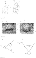
- Figure 1 shows an example of a curved rigid display screen 1 made out of different rigid segments 2 that are attached together, for example by glue and bolts.
- the curved rigid display screen 1 can be in the form of a dome or part dome, i.e. exhibiting at least a portion thereof having a three-dimensionally curved surface such as a spheroidal or spherical surface.
- a paint or coating can be applied on top of the assembled segments. This final coating is preferably applied at the site of installation, and is thus an expensive and time consuming solution.
- Figure 2 illustrates a thin flat sheet 10 extending along the axes 12 and 13, which are perpendicular and cross each other in the center of the sheet 10.
- the sheet 10 is then curved around the axis 12 and a cylindrical surface 11 is obtained.
- the line 14 (centered) is curved with a radius of curvature R.
- Figure 3 illustrates how the surface 11 is curved around an axis parallel to 13 so that a three-dimensionally curved surface 20 is obtained.
- the line 14 is curved with radius of curvature R and axis 15 (centered) is curved with radius of curvature R'. If the curved surface 20 is now rolled around an axis parallel to 12 the result is a cigar shaped volume 21 with two lines 16 and 17 with radiuses of curvature R1 and R2 respectively. Note that R1 will be different from R and R2 will be different from R'.
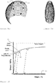
- FIG. 10 illustrates a stress 91 strain (or deformation) 92 diagram with the elastic limit 90. If the edges 22 and 23 are submitted to a stress higher than the elastic limit 90, the material will enter the plastic region and deform and/or break. At this moment, the material in the vicinity of line 16 may still deform elastically. The number t of degrees a sheet can be bent or rolled will thus depend on its geometrical- and material characteristics.
- the materials of interest for the present invention need to be rigid enough to sustain their pre-formed rounded shape, even without support.
- a material has a high E-modulus, thus the stress 91 increases fast with the strain or deformation 92.
- Such a material may be a rigid plastic having a modulus of elasticity either in flexure or in tension greater than 700 MPa at 23°C and 50% humidity, when tested in accordance with ASTM methods D747, D790, D 638, or D 882 (see Compilation of ASTM standard definitions, Fourth Edition 1979).
- the flexibility of a material is determined by a combination of its modulus in bending or tension, its thickness and its extension at break. However as weight is an important characteristic for handling a transport a higher modulus of a thinner material can be preferable.
- the present invention allows a variety of combinations of material properties such as thickness, bending or tensile modulus and extension at break.
- a suitable thickness range can be between 1.5 and 5 mm average. If a sheet of such a material is very heavily curved, for example having the shape of a complete semi-sphere, it is not possible to bend it around its centre axis without breaking it. The deformation and the associated stress rapidly rises to values higher than the elastic limit 90.
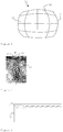
- Figure 4 shows an embodiment of the present invention where the curved display has two truncations opposite each other.
- a remedy is to cut out a piece of material of the sphere, as shown at 32 and 33 in figure 4 so that the radius of curvature in its deformed shape is increased. This will reduce the deformation and the associated induced stress so that the stresses experienced at the positions indicated by 32 and 33 will remain within the elastic range. In principle this remedy is also valid for a curved screen that is not perfectly spherical but has more than one radius of curvature.
- a related remedy is to use a smaller field or fields of view 40 and/or 41 of the screen, vertically and/or horizontally (see Figure 5 ).
- Figure 5 illustrates the field of view of an image.
- the field of view can be described as an angle between the lines originating from the observer to the edges of the image. It is described for the vertical, horizontal and sometimes diagonal extent of the image.
- Figure 5 a) illustrates the vertical field of view 40 of a flat object 44 experienced by the observer 42
- figure 5 b) illustrates the horizontal field of view 41 for the flat object 44 experienced by the observer 42.
- the line of sight 43 can be used to differentiate between the positive vertical (above) and negative vertical (below) field of view. In two- and three dimensions the line of sight will be a line or a curve respectively and can be called the horizon.
- the human limit for the total vertical field of view 40 is about 135 degrees.
- the distribution of the field of view does not have to be symmetrical around the reference line 43 (or the horizon).
- the horizontal field of view of the screen is at least 75 degrees and the vertical field of view of the screen is at least 75 degrees.
- the installation can comprise the steps of deploying the screen and inserting it into a supporting frame 50 as shown schematically in figure 6 , with means of fastening.
- the support is built up of elongated structures 51 leaving empty spaces 52 between and should not be limited to the layout in figure 6 .
- the means of fastening can be for example magnets, hook and loop fasteners such as Velcro, or screws, but should not be limited hereto.
- the means of fastening may be distributed over the surface of the screen that is not used for intentionally displaying an image, hereafter referred to as the non-displaying surface.
- the means for fastening can also be applied along the edges of the screen, for example directly attached on the screen.
- Figures 7 and 9a and b show how the screen can be rolled whereby a reduction can be achieved from 240 cm to 750 mm, which fits into or passes through a standard door.
- Figure 7 and Figure 9b show an embodiment of the present invention where the curved display screen 30 is rolled up around one of its vertical axes, 61, into a cigar-like shaped roll 60. The diameter in the rolled-up state can be significantly decreased. For a smaller sized display it can be possible to pass through a standard door, e.g. having a width of clear space of at least 750mm or at least 800 mm.
- the screen has a deployed diameter of about 240 cm it could be rolled-up to a diameter of about 750 mm which is consistent with the above dimensions of at least 750 mm, e.g. at least 800 mm. But larger screens with for example diameters like 500 cm can also be rolled in order to decrease the diameter. These should, however, not be seen as limiting examples.
- Figure 8 shows a cross section of an embodiment of the present invention.
- the curved display screen can be used for front- or rear projection.
- the substrate 70 has to be transparent for visible light and the optical coating 71 can be designed to diffuse the transmitted light.
- the substrate 70 can be transparent or non-transparent.
- the coating 70 may for front projection be a reflective coating. It is also possible to have coatings on both sides of substrate 70 (not shown here).
- the screen substrate can be implemented with various types of materials, for example glass fiber reinforced plastics or polycarbonate or any other transparent light weight material for the rear-projection embodiment.
- non-transparent materials like steel, aluminum or other alloys, or any other material that would give a light weight screen.
Landscapes
- Physics & Mathematics (AREA)
- General Physics & Mathematics (AREA)
- Overhead Projectors And Projection Screens (AREA)
Description
- The present invention relates to curved projection screens, in particular projection screens that are curved in three dimensions.
- Projection screens that are shaped like a sphere or part of a sphere, so-called dome screens or immersive screens, can be used in a variety of fields, such as simulation, training, high end gaming, immersive display for virtual and augmented reality, etc. It is crucial for the quality of the projected image to have a smooth and bulge-free surface in order to provide a high image quality. This can be obtained by implementing the screen in a rigid material that resist deformation that could arise from draft, non-uniform tension between fixation points, its own weight etc. It is common to implement such rigid screens by dividing them into smaller segments, in order to facilitate logistics. In this way it is possible to use standard trucks or containers to carry the screen, or to be able to pass through a standard door or window when bringing the screen into a building. The dimensions of the opening width of a "standard door" are typically in the range 750 to 800mm. For example, the Housing Standards Review - Illustrative Technical Standards Developed by the Working groups from the UK Department for Communities and Local Government dated August 2013 details requirements for communal entrances, both internal and external A communal entrance door to a building containing flats (or other dwelling types served by a communal entrance or doors) should have a clear opening width of at least 800mm. All external gates, openings or doorways within an approach route should provide a minimum clear opening width of 850mm. Secondary entrance doors, for example within a lobby or porch, should provide a minimum clear opening width of 800mm. For a private entrance area a door should have a clear opening width of at least 800mm. The doorway to any habitable room, the kitchen, and the room containing the WC should provide a minimum clear opening width of 750mm.
- At the installation site, the screen is mounted by putting the segments together. A visible seam between the screen segments would disturb the projected image, therefore these seems are concealed with additional fill up and painting. To assemble and finish the screen surface on-site requires a substantial amount of labour and equipment. The final coatings or paints should also be applied by specially trained people.
-
US5724775 discloses a multi-pieced portable projection dome that is constructed from a plurality of rigid panels. -
US6712477 discloses a non-deployable hemispherical projection dome.CN2932438Y discloses a method of manufacture of a cylindrical rollable projection screen. - The present invention therefore seeks to provide a screen that can be curved in three dimensions and that is suitable for high quality image projection. The screen comprises a one-piece seamless curved substrate that can be rolled or bent for better suiting logistic requirements. The edge of the screen is shaped so that it can deform elastically when the screen is bent to a certain degree.
- According to an aspect of the present invention there is provided a curved projection screen comprising a one-piece seamless substrate having a three-dimensional curvature. Said screen is arranged for being bent to a certain degree around one of its axes so that the smallest deformation of the screen is elastic, wherein the edge of said screen has been shaped so that its deformation during the above mentioned degree of bending is also elastic.
- In one aspect the present invention provides a curved projection screen comprising a self-supporting seamless substrate, having a three-dimensional curvature and with at least one pair of truncations on two opposing truncated edges, each pair being positioned at the ends of an axis, wherein said screen is rolled around one of the axes so that the smallest diameter of the screen in its rolled state is about 30% of the diameter in its deployed state.
- The shape depends on the degree of bending. This shape can comprise at least two truncations of the curved surface whereof two truncations are placed opposite to each other and perpendicular to the axis of bending. In this way the radius of curvature in the bended state is increased and the deformation and corresponding induced stress is decreased so that it is elastically deformed. Further can the substrate be coated, before shipping and installation, with at least one optical coating on the concave or convex surface or on both surfaces. This avoids the additional step of applying the coating at the installation site.
- According to another aspect of the invention there is provided a curved projection screen comprising a one-piece seamless substrate having a three-dimensional curvature. Said screen is arranged for being bent to a certain degree around one of its axes so that the smallest deformation of the screen is elastic, wherein the edge of said screen has been shaped so that its deformation during the above mentioned degree of bending is also elastic.
- Said screen has means for fastening attached along a surface that is not intentionally displaying a projected image, for example on the backside of a front projecting screen, or along the edge on a rear-projecting screen. The means for fastening can be magnets or Velcro or screws, any combination thereof or any other type of fastening. With the means for fastening, the screen can be attached to a supporting frame, to make sure the shape of the screen stays as intended.
- According to another aspect of the invention there is provided a curved projection screen comprising a one-piece seamless substrate having a three-dimensional curvature. Said screen is arranged for being bent to a certain degree around one of its axes so that the smallest deformation of the screen is elastic, wherein the edge of said screen has been shaped so that its deformation during the above mentioned degree of bending is also elastic.
- Said screen has a plurality of alignment magnets attached to the backside of the screen. Reference magnets can then be placed on the displaying side of the screen so that they are attracted to the alignment magnets and attached to the screen. This provides a non-electrical and simple method for obtaining reference points for the alignment of the projected images. A removal magnet, being larger and stronger than the reference magnet can be positioned on top of the reference magnet to remove it.
-
-
Figure 1 shows a segmented curved display screen. -
Figure 2 shows a plane sheet bent into a cylindrical shape. -
Figure 3 shows a sheet curved in three dimensions and then bent along one of its axes. -
Figure 4 shows an embodiment of the present invention where the curved display has two truncations opposite each other. -
Figure 5 shows an example of a) vertical- and b) horizontal field of view. -
Figure 6 shows a support structure where a curved screen can be attached. -
Figure 7 shows an embodiment of the present invention in a rolled-up state. -
Figure 8 shows a cross section of an embodiment of the present invention. -
Figure 9a shows an embodiment of the present invention where an alignment aid is provided by means of magnets.Figure 9b shows an embodiment of the present invention rolled to a cigar shapeFigure 10 shows a stress-strain diagram. - The present invention will be described with respect to particular embodiments and with reference to certain drawings but the invention is not limited thereto but only by the claims. The drawings described are only schematic and are non-limiting. In the drawings, the size of some of the elements may be exaggerated and not drawn on scale for illustrative purposes. Where the term "comprising" is used in the present description and claims, it does not exclude other elements or steps. Furthermore, the terms first, second, third and the like in the description and in the claims, are used for distinguishing between similar elements and not necessarily for describing a sequential or chronological order. It is to be understood that the terms so used are interchangeable under appropriate circumstances and that the embodiments of the invention described herein are capable of operation in other sequences than described or illustrated herein.
- The Meriam Webster Dictionary states that "truncate" means to shorten by or as if by cutting off.
-
Figure 1 shows an example of a curved rigid display screen 1 made out of differentrigid segments 2 that are attached together, for example by glue and bolts. The curved rigid display screen 1 can be in the form of a dome or part dome, i.e. exhibiting at least a portion thereof having a three-dimensionally curved surface such as a spheroidal or spherical surface. To hide the seams on the inside display surface 3 a paint or coating can be applied on top of the assembled segments. This final coating is preferably applied at the site of installation, and is thus an expensive and time consuming solution. -
Figure 2 illustrates a thinflat sheet 10 extending along theaxes sheet 10. Thesheet 10 is then curved around theaxis 12 and acylindrical surface 11 is obtained. The line 14 (centered) is curved with a radius of curvature R. -
Figure 3 illustrates how thesurface 11 is curved around an axis parallel to 13 so that a three-dimensionallycurved surface 20 is obtained. Theline 14 is curved with radius of curvature R and axis 15 (centered) is curved with radius of curvature R'. If thecurved surface 20 is now rolled around an axis parallel to 12 the result is a cigar shapedvolume 21 with twolines - The stress experienced by
surface 11 will be substantially the same along theline 12 since the radius of curvature is the same. The stress experienced byvolume 21 will be higher at theedges line 16.Figure 10 illustrates astress 91 strain (or deformation) 92 diagram with theelastic limit 90. If theedges elastic limit 90, the material will enter the plastic region and deform and/or break. At this moment, the material in the vicinity ofline 16 may still deform elastically. The number t of degrees a sheet can be bent or rolled will thus depend on its geometrical- and material characteristics. - The materials of interest for the present invention need to be rigid enough to sustain their pre-formed rounded shape, even without support. Such a material has a high E-modulus, thus the
stress 91 increases fast with the strain ordeformation 92. Such a material may be a rigid plastic having a modulus of elasticity either in flexure or in tension greater than 700 MPa at 23°C and 50% humidity, when tested in accordance with ASTM methods D747, D790, D 638, or D 882 (see Compilation of ASTM standard definitions, Fourth Edition 1979). The flexibility of a material is determined by a combination of its modulus in bending or tension, its thickness and its extension at break. However as weight is an important characteristic for handling a transport a higher modulus of a thinner material can be preferable. Thus the present invention allows a variety of combinations of material properties such as thickness, bending or tensile modulus and extension at break. - An example of a suitable material is given in this table:
Property Test standard Value Bending modulus ISO 178 8.3 GPa Bending strength ISO 178 235.1 MPa Tensile strength ISO 527 91.8 MPa Extension at break ISO 527 6.64% Weight 1 layer of 450g/m2 Thickness 2 ± 0.5 mm - The standards refer to those applicable on 16 September 2013. A suitable thickness range can be between 1.5 and 5 mm average. If a sheet of such a material is very heavily curved, for example having the shape of a complete semi-sphere, it is not possible to bend it around its centre axis without breaking it. The deformation and the associated stress rapidly rises to values higher than the
elastic limit 90.Figure 4 shows an embodiment of the present invention where the curved display has two truncations opposite each other. A remedy is to cut out a piece of material of the sphere, as shown at 32 and 33 infigure 4 so that the radius of curvature in its deformed shape is increased. This will reduce the deformation and the associated induced stress so that the stresses experienced at the positions indicated by 32 and 33 will remain within the elastic range. In principle this remedy is also valid for a curved screen that is not perfectly spherical but has more than one radius of curvature. - A related remedy is to use a smaller field or fields of
view 40 and/or 41 of the screen, vertically and/or horizontally (seeFigure 5 ). -
Figure 5 illustrates the field of view of an image. The field of view can be described as an angle between the lines originating from the observer to the edges of the image. It is described for the vertical, horizontal and sometimes diagonal extent of the image.Figure 5 a) illustrates the vertical field ofview 40 of aflat object 44 experienced by theobserver 42 andfigure 5 b) illustrates the horizontal field ofview 41 for theflat object 44 experienced by theobserver 42. The line of sight 43 can be used to differentiate between the positive vertical (above) and negative vertical (below) field of view. In two- and three dimensions the line of sight will be a line or a curve respectively and can be called the horizon. The human limit for the total vertical field ofview 40 is about 135 degrees. The distribution of the field of view does not have to be symmetrical around the reference line 43 (or the horizon). In one embodiment of the present invention, the horizontal field of view of the screen is at least 75 degrees and the vertical field of view of the screen is at least 75 degrees. - With embodiments of the present invention it is possible to have a pre-coated seamless screen that is easy to bring into a building and is fast to install. The installation can comprise the steps of deploying the screen and inserting it into a supporting
frame 50 as shown schematically infigure 6 , with means of fastening. As shown inFigure 6 , the support is built up ofelongated structures 51 leavingempty spaces 52 between and should not be limited to the layout infigure 6 . The means of fastening can be for example magnets, hook and loop fasteners such as Velcro, or screws, but should not be limited hereto. The means of fastening may be distributed over the surface of the screen that is not used for intentionally displaying an image, hereafter referred to as the non-displaying surface. The means for fastening can also be applied along the edges of the screen, for example directly attached on the screen. Alternatively there can be part of the support structure placed so that it clamps the screen edge and the means for fastening is fixing this clamp to the screen. It is then possible to apply the means for fastening only along the edges of the screen. A mixture of the two is also possible. Fastening the screen provides further stability and assures the projection surface remains in its intended shape. -
Figures 7 and9a and b show how the screen can be rolled whereby a reduction can be achieved from 240 cm to 750 mm, which fits into or passes through a standard door.Figure 7 andFigure 9b show an embodiment of the present invention where thecurved display screen 30 is rolled up around one of its vertical axes, 61, into a cigar-likeshaped roll 60. The diameter in the rolled-up state can be significantly decreased. For a smaller sized display it can be possible to pass through a standard door, e.g. having a width of clear space of at least 750mm or at least 800 mm. For example, if the screen has a deployed diameter of about 240 cm it could be rolled-up to a diameter of about 750 mm which is consistent with the above dimensions of at least 750 mm, e.g. at least 800 mm. But larger screens with for example diameters like 500 cm can also be rolled in order to decrease the diameter. These should, however, not be seen as limiting examples. -
Figure 8 shows a cross section of an embodiment of the present invention. The curved display screen can be used for front- or rear projection. For a rear-projection screen thesubstrate 70 has to be transparent for visible light and theoptical coating 71 can be designed to diffuse the transmitted light. For a front projection screen thesubstrate 70 can be transparent or non-transparent. Thecoating 70 may for front projection be a reflective coating. It is also possible to have coatings on both sides of substrate 70 (not shown here). The screen substrate can be implemented with various types of materials, for example glass fiber reinforced plastics or polycarbonate or any other transparent light weight material for the rear-projection embodiment. For the front projection embodiment it is also possible to use non-transparent materials like steel, aluminum or other alloys, or any other material that would give a light weight screen. -
Figure 9a shows an embodiment of the present invention intended for front projection. Magnets 81 (only one indicated) are distributed over thenon-displaying screen surface 80. These magnets will be referred to as alignment magnets. When the screen is installed, additional magnets, referred to as reference magnets (not shown), can be attached to the screen at the location of the reference magnets. For example a plurality of alignment magnets can be pre-mounted on the backside of the screen. If several images are tiled, these magnets can be used as reference points during the alignment of the projectors. After the alignment is done, a magnet that is bigger and stronger than one of the reference magnets can be used for the removal of the reference magnets. For example neodymium magnets can be used, or any other strong type of magnet. In contrast to additional complex electrical equipment for alignment, this is a simple and fast solution.
Claims (13)
- A curved projection screen comprising a self-supporting seamless substrate, having a three-dimensional curvature and with at least one pair of truncations on two opposing truncated edges, each pair being positioned at the ends of an axis, wherein said screen is rolled around said axis so that the smallest diameter of the screen in its rolled state is about 30% of the diameter in its deployed state.
- A curved projection screen according to claim 1, comprising a one-piece seamless substrate, said substrate being pre-formed into a three-dimensional curvature with at least one axis of bending.
- A curved projection screen according to claim 1 or 2, wherein the truncations on opposing sides along at least one axis are of different length.
- A curved projection screen according to any of claims 1 to 3, wherein an optical coating is deposited onto the screen on a concave or convex surface or on both surfaces.
- A curved projection screen according to any of the claims 1-4, wherein the screen comprises means for fastening attached along a non-displaying part of the screen.
- A curved projection screen according to claim 5, wherein the means for fastening are magnets or hook and loop fasteners or screws or any combination thereof.
- A curved projection screen according to any of the claims 1 to 6, wherein the substrate is made out of glass fiber reinforced plastics or polycarbonate or a light-weight metal.
- A curved projection screen according to any of the claims 1 to 7, wherein a plurality of alignment magnets are pre-mounted on the backside of the screen.
- A curved projection screen according to claim 8, wherein a plurality of reference magnets are placed on the displaying side of the screen at positions corresponding to the alignment magnets, so that the reference magnets attracts the alignment magnets which are hereby attached to the screen.
- A curved projection screen according to claim 8 or claim 9, wherein a removal magnet, which is larger and stronger than the reference magnet, is positioned on top of a reference magnet.
- A curved projection screen according to any of the claims 1 to 10 comprising neodymium magnets.
- A method of transporting and installing a self-supporting curved projection screen according to any of the claims 1 to 11, the method comprising the steps of, at the site of departure, rolling said screen around said axis to about 30% of its diameter in its deployed state, carrying said screen through at least one standard door, un-rolling said screen at the site of destination, and installing said screen in a supporting frame with help of means for fastening.
- A method of transporting and installing a self-supporting curved projection screen according to claim 12, wherein the step of installing comprises the steps of:- placing reference magnets on the displaying side of the screen on positions corresponding to pre-mounted alignment magnets positioned on the backside of the screen,- using the reference magnets as reference points when aligning the corresponding projection source, and- placing a removal magnet on a reference magnet and removing the reference magnet from the screen.
Applications Claiming Priority (2)
| Application Number | Priority Date | Filing Date | Title |
|---|---|---|---|
| GB1408159.0A GB2526081A (en) | 2014-05-08 | 2014-05-08 | Curved projection screen |
| PCT/EP2015/060028 WO2015169889A1 (en) | 2014-05-08 | 2015-05-07 | Curved projection screen |
Publications (2)
| Publication Number | Publication Date |
|---|---|
| EP3140696A1 EP3140696A1 (en) | 2017-03-15 |
| EP3140696B1 true EP3140696B1 (en) | 2019-07-10 |
Family
ID=51032439
Family Applications (1)
| Application Number | Title | Priority Date | Filing Date |
|---|---|---|---|
| EP15723668.8A Active EP3140696B1 (en) | 2014-05-08 | 2015-05-07 | Curved projection screen |
Country Status (5)
| Country | Link |
|---|---|
| US (1) | US9733560B2 (en) |
| EP (1) | EP3140696B1 (en) |
| CN (1) | CN106462046B (en) |
| GB (1) | GB2526081A (en) |
| WO (1) | WO2015169889A1 (en) |
Families Citing this family (15)
| Publication number | Priority date | Publication date | Assignee | Title |
|---|---|---|---|---|
| US10025549B1 (en) * | 2015-07-22 | 2018-07-17 | Steve Welck | Immersive digital display systems |
| EP3432069A4 (en) * | 2016-03-16 | 2019-03-06 | Ricoh Company, Ltd. | Screen member and image display device |
| USD825001S1 (en) * | 2016-11-09 | 2018-08-07 | Danièle Henkel To Go | Promotional signage |
| EP3379828A1 (en) | 2017-03-23 | 2018-09-26 | Thomson Licensing | Device and method for immersive visual representations and individual head equipment |
| CN107024827A (en) * | 2017-04-29 | 2017-08-08 | 重庆城市管理职业学院 | Exhibitions movement curtain |
| JP7049078B2 (en) * | 2017-07-19 | 2022-04-06 | 日本無線株式会社 | Simulator dome and screen grip jig |
| USD837212S1 (en) * | 2017-09-27 | 2019-01-01 | Michael Ross Catania | Dome shaped monitor |
| USD898225S1 (en) * | 2018-08-21 | 2020-10-06 | Nanolumens Acquisition, Inc. | Hemispherical shaped light emitting digital display |
| USD903657S1 (en) * | 2018-11-20 | 2020-12-01 | Michael R Catania | Personal computer |
| USD903658S1 (en) * | 2018-11-20 | 2020-12-01 | Michael Ross Catania | Personal computer |
| USD903659S1 (en) * | 2018-11-24 | 2020-12-01 | Michael Ross Catania | Personal computer |
| DE102019105855A1 (en) | 2019-03-07 | 2020-09-10 | Deutsche Post Ag | Vehicle with display device |
| JPWO2023094945A1 (en) * | 2021-11-26 | 2023-06-01 | ||
| USD1072275S1 (en) * | 2022-12-06 | 2025-04-22 | Skulpod (Pty) Ltd | Modular shelter |
| CN115841788B (en) * | 2022-12-26 | 2025-09-26 | 歌尔科技有限公司 | Segmented display screen and VR equipment |
Family Cites Families (20)
| Publication number | Priority date | Publication date | Assignee | Title |
|---|---|---|---|---|
| US2888072A (en) * | 1956-06-20 | 1959-05-26 | Radiant Mfg Corp | Portable cinemascope screen assembly |
| US3037424A (en) | 1957-01-15 | 1962-06-05 | Capetta Albert | Process for the realization of a relief screen and screen obtained by the process |
| US3054325A (en) * | 1960-08-22 | 1962-09-18 | Crockwell Douglass | Projection screen |
| US3348897A (en) * | 1964-04-03 | 1967-10-24 | Hourdiaux Jules | Curved screens for projecting motion picture films or the like |
| US3998522A (en) * | 1975-03-24 | 1976-12-21 | Intercontinental Satellite Network, Inc. | Screen for exhibiting projected images |
| US4022522A (en) * | 1975-06-30 | 1977-05-10 | Irvin Industries, Inc. | Projection screen |
| US5724775A (en) | 1996-01-29 | 1998-03-10 | Alternate Realities Corporation | Multi-pieced, portable projection dome and method of assembling the same |
| US6530667B1 (en) | 2000-02-08 | 2003-03-11 | Elumens Corporation | Optical projection system including projection dome |
| US6501599B1 (en) * | 2001-08-14 | 2002-12-31 | John William Randolph | Double concave screen and method of assembly |
| JP2004301923A (en) * | 2003-03-28 | 2004-10-28 | Olympus Corp | Reflection screen device and projection system |
| JP2006003409A (en) * | 2004-06-15 | 2006-01-05 | Olympus Corp | Image projection system |
| US7766483B2 (en) * | 2005-04-06 | 2010-08-03 | Suresh Balu | Optical projection system and methods for configuring the same |
| US7933068B2 (en) | 2005-09-30 | 2011-04-26 | Seiko Epson Corporation | Reconfigurable projection-screen system |
| US7340953B2 (en) * | 2006-03-15 | 2008-03-11 | Browne & Co. | Liquid measuring vessel |
| CN2932438Y (en) | 2006-07-05 | 2007-08-08 | 张华� | Reelable hard projection screen |
| CN201775939U (en) * | 2010-01-29 | 2011-03-30 | 傅慧任 | A desktop bowling game device |
| DE202010010853U1 (en) | 2010-07-30 | 2010-10-21 | Despar Systeme Ag | Curved projection screen |
| CN202841361U (en) * | 2012-09-21 | 2013-03-27 | 厦门美屏电子有限公司 | Non-split ultra-large screen display system |
| CN202999545U (en) * | 2012-12-19 | 2013-06-19 | 王子淳 | Splitting type badge |
| GB2518461A (en) * | 2013-09-23 | 2015-03-25 | Barco Nv | Seamless display screen for fast installation |
-
2014
- 2014-05-08 GB GB1408159.0A patent/GB2526081A/en not_active Withdrawn
-
2015
- 2015-05-07 WO PCT/EP2015/060028 patent/WO2015169889A1/en not_active Ceased
- 2015-05-07 US US15/308,006 patent/US9733560B2/en active Active
- 2015-05-07 EP EP15723668.8A patent/EP3140696B1/en active Active
- 2015-05-07 CN CN201580023934.XA patent/CN106462046B/en active Active
Non-Patent Citations (1)
| Title |
|---|
| None * |
Also Published As
| Publication number | Publication date |
|---|---|
| CN106462046B (en) | 2020-07-28 |
| US20170052438A1 (en) | 2017-02-23 |
| GB201408159D0 (en) | 2014-06-25 |
| WO2015169889A1 (en) | 2015-11-12 |
| CN106462046A (en) | 2017-02-22 |
| EP3140696A1 (en) | 2017-03-15 |
| US9733560B2 (en) | 2017-08-15 |
| GB2526081A (en) | 2015-11-18 |
Similar Documents
| Publication | Publication Date | Title |
|---|---|---|
| US9733560B2 (en) | Curved projection screen | |
| US20200241349A1 (en) | Ubiquitously Mountable Image Display System | |
| CN105954966B (en) | Projection screen accessory, the method for building projection screen equipment and the method convenient for building projection screen equipment | |
| US20170226739A1 (en) | Curved screen frame and theater comprising same | |
| EP3559538B1 (en) | Display module for a temporary exhibition stand | |
| US9076354B1 (en) | Sign stanchion | |
| US9785045B2 (en) | Seamless projection screen for fast installation | |
| US7086187B2 (en) | Advertising display system and method | |
| CN101522076A (en) | Shelf for shelving unit | |
| EP3235636A1 (en) | Glass resin laminate | |
| EP2506066A3 (en) | Display and electronic unit | |
| US9711069B2 (en) | Freestanding display | |
| EP2975601A1 (en) | Led display device | |
| US20210335150A1 (en) | Light reflecting decorative panel | |
| US20060248768A1 (en) | Systems and methods for providing public space advertising | |
| WO2003091802A1 (en) | Screen for both-side view projector | |
| US9840868B2 (en) | Shade storage and deployment scheme | |
| CN111986560A (en) | a sign | |
| CN208858700U (en) | A kind of screen splicing device | |
| JP2020197247A (en) | Assembly-type stand for desktop electronic apparatus and image projection system | |
| CN205894547U (en) | Stand outsourcing structure of quick installation of instrument of exempting from | |
| EP1510996A2 (en) | Display apparatus | |
| CN105161017B (en) | A kind of unit splicing part of LED unit screen body | |
| US20060086021A1 (en) | Display apparatus | |
| Nijsse | Corrugated glass as improvement to the structural resistance of glass |
Legal Events
| Date | Code | Title | Description |
|---|---|---|---|
| STAA | Information on the status of an ep patent application or granted ep patent |
Free format text: STATUS: THE INTERNATIONAL PUBLICATION HAS BEEN MADE |
|
| PUAI | Public reference made under article 153(3) epc to a published international application that has entered the european phase |
Free format text: ORIGINAL CODE: 0009012 |
|
| STAA | Information on the status of an ep patent application or granted ep patent |
Free format text: STATUS: REQUEST FOR EXAMINATION WAS MADE |
|
| 17P | Request for examination filed |
Effective date: 20161020 |
|
| AK | Designated contracting states |
Kind code of ref document: A1 Designated state(s): AL AT BE BG CH CY CZ DE DK EE ES FI FR GB GR HR HU IE IS IT LI LT LU LV MC MK MT NL NO PL PT RO RS SE SI SK SM TR |
|
| AX | Request for extension of the european patent |
Extension state: BA ME |
|
| DAV | Request for validation of the european patent (deleted) | ||
| DAX | Request for extension of the european patent (deleted) | ||
| GRAP | Despatch of communication of intention to grant a patent |
Free format text: ORIGINAL CODE: EPIDOSNIGR1 |
|
| STAA | Information on the status of an ep patent application or granted ep patent |
Free format text: STATUS: GRANT OF PATENT IS INTENDED |
|
| INTG | Intention to grant announced |
Effective date: 20190130 |
|
| GRAS | Grant fee paid |
Free format text: ORIGINAL CODE: EPIDOSNIGR3 |
|
| GRAA | (expected) grant |
Free format text: ORIGINAL CODE: 0009210 |
|
| STAA | Information on the status of an ep patent application or granted ep patent |
Free format text: STATUS: THE PATENT HAS BEEN GRANTED |
|
| AK | Designated contracting states |
Kind code of ref document: B1 Designated state(s): AL AT BE BG CH CY CZ DE DK EE ES FI FR GB GR HR HU IE IS IT LI LT LU LV MC MK MT NL NO PL PT RO RS SE SI SK SM TR |
|
| REG | Reference to a national code |
Ref country code: GB Ref legal event code: FG4D |
|
| REG | Reference to a national code |
Ref country code: CH Ref legal event code: EP Ref country code: AT Ref legal event code: REF Ref document number: 1154206 Country of ref document: AT Kind code of ref document: T Effective date: 20190715 |
|
| REG | Reference to a national code |
Ref country code: DE Ref legal event code: R096 Ref document number: 602015033483 Country of ref document: DE |
|
| REG | Reference to a national code |
Ref country code: IE Ref legal event code: FG4D |
|
| REG | Reference to a national code |
Ref country code: NL Ref legal event code: MP Effective date: 20190710 |
|
| REG | Reference to a national code |
Ref country code: LT Ref legal event code: MG4D |
|
| REG | Reference to a national code |
Ref country code: AT Ref legal event code: MK05 Ref document number: 1154206 Country of ref document: AT Kind code of ref document: T Effective date: 20190710 |
|
| PG25 | Lapsed in a contracting state [announced via postgrant information from national office to epo] |
Ref country code: FI Free format text: LAPSE BECAUSE OF FAILURE TO SUBMIT A TRANSLATION OF THE DESCRIPTION OR TO PAY THE FEE WITHIN THE PRESCRIBED TIME-LIMIT Effective date: 20190710 Ref country code: NO Free format text: LAPSE BECAUSE OF FAILURE TO SUBMIT A TRANSLATION OF THE DESCRIPTION OR TO PAY THE FEE WITHIN THE PRESCRIBED TIME-LIMIT Effective date: 20191010 Ref country code: AT Free format text: LAPSE BECAUSE OF FAILURE TO SUBMIT A TRANSLATION OF THE DESCRIPTION OR TO PAY THE FEE WITHIN THE PRESCRIBED TIME-LIMIT Effective date: 20190710 Ref country code: LT Free format text: LAPSE BECAUSE OF FAILURE TO SUBMIT A TRANSLATION OF THE DESCRIPTION OR TO PAY THE FEE WITHIN THE PRESCRIBED TIME-LIMIT Effective date: 20190710 Ref country code: SE Free format text: LAPSE BECAUSE OF FAILURE TO SUBMIT A TRANSLATION OF THE DESCRIPTION OR TO PAY THE FEE WITHIN THE PRESCRIBED TIME-LIMIT Effective date: 20190710 Ref country code: BG Free format text: LAPSE BECAUSE OF FAILURE TO SUBMIT A TRANSLATION OF THE DESCRIPTION OR TO PAY THE FEE WITHIN THE PRESCRIBED TIME-LIMIT Effective date: 20191010 Ref country code: PT Free format text: LAPSE BECAUSE OF FAILURE TO SUBMIT A TRANSLATION OF THE DESCRIPTION OR TO PAY THE FEE WITHIN THE PRESCRIBED TIME-LIMIT Effective date: 20191111 Ref country code: NL Free format text: LAPSE BECAUSE OF FAILURE TO SUBMIT A TRANSLATION OF THE DESCRIPTION OR TO PAY THE FEE WITHIN THE PRESCRIBED TIME-LIMIT Effective date: 20190710 Ref country code: HR Free format text: LAPSE BECAUSE OF FAILURE TO SUBMIT A TRANSLATION OF THE DESCRIPTION OR TO PAY THE FEE WITHIN THE PRESCRIBED TIME-LIMIT Effective date: 20190710 |
|
| PG25 | Lapsed in a contracting state [announced via postgrant information from national office to epo] |
Ref country code: AL Free format text: LAPSE BECAUSE OF FAILURE TO SUBMIT A TRANSLATION OF THE DESCRIPTION OR TO PAY THE FEE WITHIN THE PRESCRIBED TIME-LIMIT Effective date: 20190710 Ref country code: GR Free format text: LAPSE BECAUSE OF FAILURE TO SUBMIT A TRANSLATION OF THE DESCRIPTION OR TO PAY THE FEE WITHIN THE PRESCRIBED TIME-LIMIT Effective date: 20191011 Ref country code: RS Free format text: LAPSE BECAUSE OF FAILURE TO SUBMIT A TRANSLATION OF THE DESCRIPTION OR TO PAY THE FEE WITHIN THE PRESCRIBED TIME-LIMIT Effective date: 20190710 Ref country code: LV Free format text: LAPSE BECAUSE OF FAILURE TO SUBMIT A TRANSLATION OF THE DESCRIPTION OR TO PAY THE FEE WITHIN THE PRESCRIBED TIME-LIMIT Effective date: 20190710 Ref country code: IS Free format text: LAPSE BECAUSE OF FAILURE TO SUBMIT A TRANSLATION OF THE DESCRIPTION OR TO PAY THE FEE WITHIN THE PRESCRIBED TIME-LIMIT Effective date: 20191110 Ref country code: ES Free format text: LAPSE BECAUSE OF FAILURE TO SUBMIT A TRANSLATION OF THE DESCRIPTION OR TO PAY THE FEE WITHIN THE PRESCRIBED TIME-LIMIT Effective date: 20190710 |
|
| PG25 | Lapsed in a contracting state [announced via postgrant information from national office to epo] |
Ref country code: TR Free format text: LAPSE BECAUSE OF FAILURE TO SUBMIT A TRANSLATION OF THE DESCRIPTION OR TO PAY THE FEE WITHIN THE PRESCRIBED TIME-LIMIT Effective date: 20190710 |
|
| PG25 | Lapsed in a contracting state [announced via postgrant information from national office to epo] |
Ref country code: IT Free format text: LAPSE BECAUSE OF FAILURE TO SUBMIT A TRANSLATION OF THE DESCRIPTION OR TO PAY THE FEE WITHIN THE PRESCRIBED TIME-LIMIT Effective date: 20190710 Ref country code: PL Free format text: LAPSE BECAUSE OF FAILURE TO SUBMIT A TRANSLATION OF THE DESCRIPTION OR TO PAY THE FEE WITHIN THE PRESCRIBED TIME-LIMIT Effective date: 20190710 Ref country code: DK Free format text: LAPSE BECAUSE OF FAILURE TO SUBMIT A TRANSLATION OF THE DESCRIPTION OR TO PAY THE FEE WITHIN THE PRESCRIBED TIME-LIMIT Effective date: 20190710 Ref country code: EE Free format text: LAPSE BECAUSE OF FAILURE TO SUBMIT A TRANSLATION OF THE DESCRIPTION OR TO PAY THE FEE WITHIN THE PRESCRIBED TIME-LIMIT Effective date: 20190710 Ref country code: RO Free format text: LAPSE BECAUSE OF FAILURE TO SUBMIT A TRANSLATION OF THE DESCRIPTION OR TO PAY THE FEE WITHIN THE PRESCRIBED TIME-LIMIT Effective date: 20190710 |
|
| PG25 | Lapsed in a contracting state [announced via postgrant information from national office to epo] |
Ref country code: CZ Free format text: LAPSE BECAUSE OF FAILURE TO SUBMIT A TRANSLATION OF THE DESCRIPTION OR TO PAY THE FEE WITHIN THE PRESCRIBED TIME-LIMIT Effective date: 20190710 Ref country code: SK Free format text: LAPSE BECAUSE OF FAILURE TO SUBMIT A TRANSLATION OF THE DESCRIPTION OR TO PAY THE FEE WITHIN THE PRESCRIBED TIME-LIMIT Effective date: 20190710 Ref country code: SM Free format text: LAPSE BECAUSE OF FAILURE TO SUBMIT A TRANSLATION OF THE DESCRIPTION OR TO PAY THE FEE WITHIN THE PRESCRIBED TIME-LIMIT Effective date: 20190710 Ref country code: IS Free format text: LAPSE BECAUSE OF FAILURE TO SUBMIT A TRANSLATION OF THE DESCRIPTION OR TO PAY THE FEE WITHIN THE PRESCRIBED TIME-LIMIT Effective date: 20200224 |
|
| REG | Reference to a national code |
Ref country code: DE Ref legal event code: R097 Ref document number: 602015033483 Country of ref document: DE |
|
| PLBE | No opposition filed within time limit |
Free format text: ORIGINAL CODE: 0009261 |
|
| STAA | Information on the status of an ep patent application or granted ep patent |
Free format text: STATUS: NO OPPOSITION FILED WITHIN TIME LIMIT |
|
| PG2D | Information on lapse in contracting state deleted |
Ref country code: IS |
|
| 26N | No opposition filed |
Effective date: 20200603 |
|
| PG25 | Lapsed in a contracting state [announced via postgrant information from national office to epo] |
Ref country code: SI Free format text: LAPSE BECAUSE OF FAILURE TO SUBMIT A TRANSLATION OF THE DESCRIPTION OR TO PAY THE FEE WITHIN THE PRESCRIBED TIME-LIMIT Effective date: 20190710 |
|
| PG25 | Lapsed in a contracting state [announced via postgrant information from national office to epo] |
Ref country code: MC Free format text: LAPSE BECAUSE OF FAILURE TO SUBMIT A TRANSLATION OF THE DESCRIPTION OR TO PAY THE FEE WITHIN THE PRESCRIBED TIME-LIMIT Effective date: 20190710 Ref country code: LI Free format text: LAPSE BECAUSE OF NON-PAYMENT OF DUE FEES Effective date: 20200531 Ref country code: CH Free format text: LAPSE BECAUSE OF NON-PAYMENT OF DUE FEES Effective date: 20200531 |
|
| PG25 | Lapsed in a contracting state [announced via postgrant information from national office to epo] |
Ref country code: LU Free format text: LAPSE BECAUSE OF NON-PAYMENT OF DUE FEES Effective date: 20200507 |
|
| PG25 | Lapsed in a contracting state [announced via postgrant information from national office to epo] |
Ref country code: IE Free format text: LAPSE BECAUSE OF NON-PAYMENT OF DUE FEES Effective date: 20200507 |
|
| PG25 | Lapsed in a contracting state [announced via postgrant information from national office to epo] |
Ref country code: MT Free format text: LAPSE BECAUSE OF FAILURE TO SUBMIT A TRANSLATION OF THE DESCRIPTION OR TO PAY THE FEE WITHIN THE PRESCRIBED TIME-LIMIT Effective date: 20190710 Ref country code: CY Free format text: LAPSE BECAUSE OF FAILURE TO SUBMIT A TRANSLATION OF THE DESCRIPTION OR TO PAY THE FEE WITHIN THE PRESCRIBED TIME-LIMIT Effective date: 20190710 |
|
| PG25 | Lapsed in a contracting state [announced via postgrant information from national office to epo] |
Ref country code: MK Free format text: LAPSE BECAUSE OF FAILURE TO SUBMIT A TRANSLATION OF THE DESCRIPTION OR TO PAY THE FEE WITHIN THE PRESCRIBED TIME-LIMIT Effective date: 20190710 |
|
| PGFP | Annual fee paid to national office [announced via postgrant information from national office to epo] |
Ref country code: DE Payment date: 20250519 Year of fee payment: 11 |
|
| PGFP | Annual fee paid to national office [announced via postgrant information from national office to epo] |
Ref country code: BE Payment date: 20250520 Year of fee payment: 11 |
|
| PGFP | Annual fee paid to national office [announced via postgrant information from national office to epo] |
Ref country code: FR Payment date: 20250526 Year of fee payment: 11 |
|
| PGFP | Annual fee paid to national office [announced via postgrant information from national office to epo] |
Ref country code: GB Payment date: 20260324 Year of fee payment: 12 |