EP3140478B1 - Electromechanical lock assembly - Google Patents
Electromechanical lock assembly Download PDFInfo
- Publication number
- EP3140478B1 EP3140478B1 EP15728612.1A EP15728612A EP3140478B1 EP 3140478 B1 EP3140478 B1 EP 3140478B1 EP 15728612 A EP15728612 A EP 15728612A EP 3140478 B1 EP3140478 B1 EP 3140478B1
- Authority
- EP
- European Patent Office
- Prior art keywords
- locking
- battery
- lock assembly
- assembly
- locking bolt
- Prior art date
- Legal status (The legal status is an assumption and is not a legal conclusion. Google has not performed a legal analysis and makes no representation as to the accuracy of the status listed.)
- Active
Links
- 230000000717 retained effect Effects 0.000 description 2
- 238000000926 separation method Methods 0.000 description 2
- 229910000760 Hardened steel Inorganic materials 0.000 description 1
- 229910045601 alloy Inorganic materials 0.000 description 1
- 239000000956 alloy Substances 0.000 description 1
- 230000001413 cellular effect Effects 0.000 description 1
- 238000006073 displacement reaction Methods 0.000 description 1
- 238000009434 installation Methods 0.000 description 1
- 239000000463 material Substances 0.000 description 1
- 230000001681 protective effect Effects 0.000 description 1
- 230000007704 transition Effects 0.000 description 1
Images


Classifications
-
- E—FIXED CONSTRUCTIONS
- E05—LOCKS; KEYS; WINDOW OR DOOR FITTINGS; SAFES
- E05B—LOCKS; ACCESSORIES THEREFOR; HANDCUFFS
- E05B67/00—Padlocks; Details thereof
- E05B67/36—Padlocks with closing means other than shackles ; Removable locks, the lock body itself being the locking element; Padlocks consisting of two separable halves or cooperating with a stud
-
- E—FIXED CONSTRUCTIONS
- E05—LOCKS; KEYS; WINDOW OR DOOR FITTINGS; SAFES
- E05B—LOCKS; ACCESSORIES THEREFOR; HANDCUFFS
- E05B67/00—Padlocks; Details thereof
- E05B67/06—Shackles; Arrangement of the shackle
- E05B67/22—Padlocks with sliding shackles, with or without rotary or pivotal movement
-
- E—FIXED CONSTRUCTIONS
- E05—LOCKS; KEYS; WINDOW OR DOOR FITTINGS; SAFES
- E05B—LOCKS; ACCESSORIES THEREFOR; HANDCUFFS
- E05B47/00—Operating or controlling locks or other fastening devices by electric or magnetic means
- E05B47/0001—Operating or controlling locks or other fastening devices by electric or magnetic means with electric actuators; Constructional features thereof
-
- E—FIXED CONSTRUCTIONS
- E05—LOCKS; KEYS; WINDOW OR DOOR FITTINGS; SAFES
- E05B—LOCKS; ACCESSORIES THEREFOR; HANDCUFFS
- E05B47/00—Operating or controlling locks or other fastening devices by electric or magnetic means
- E05B47/06—Controlling mechanically-operated bolts by electro-magnetically-operated detents
-
- E—FIXED CONSTRUCTIONS
- E05—LOCKS; KEYS; WINDOW OR DOOR FITTINGS; SAFES
- E05B—LOCKS; ACCESSORIES THEREFOR; HANDCUFFS
- E05B65/00—Locks or fastenings for special use
- E05B65/48—Hasp locks
-
- E—FIXED CONSTRUCTIONS
- E05—LOCKS; KEYS; WINDOW OR DOOR FITTINGS; SAFES
- E05B—LOCKS; ACCESSORIES THEREFOR; HANDCUFFS
- E05B67/00—Padlocks; Details thereof
- E05B67/02—Cases
-
- E—FIXED CONSTRUCTIONS
- E05—LOCKS; KEYS; WINDOW OR DOOR FITTINGS; SAFES
- E05B—LOCKS; ACCESSORIES THEREFOR; HANDCUFFS
- E05B47/00—Operating or controlling locks or other fastening devices by electric or magnetic means
- E05B2047/0048—Circuits, feeding, monitoring
- E05B2047/0057—Feeding
- E05B2047/0058—Feeding by batteries
-
- E—FIXED CONSTRUCTIONS
- E05—LOCKS; KEYS; WINDOW OR DOOR FITTINGS; SAFES
- E05B—LOCKS; ACCESSORIES THEREFOR; HANDCUFFS
- E05B47/00—Operating or controlling locks or other fastening devices by electric or magnetic means
- E05B2047/0094—Mechanical aspects of remotely controlled locks
Definitions
- the present invention relates generally to high security locks and particularly to an electromechanical lock assembly.
- Padlocks that have protected hasps are known in the art and are referred herein as hasp locks.
- a hasp lock each side of a door opening (e.g., a hinged door and a jamb, or two sliding doors) is provided with a protective hasp for a lock body and shackle of a lock.
- a shackle or locking pin locks the hasp bodies together.
- US Patent 7946142 to Matyko et al. describes a hasp lock, which includes a first member and a second member.
- the two members include complimentary shaped protrusions and recesses that mate with one another.
- a locking assembly is housed in the first member, including a cylinder lock that brings a locking element into locking engagement with a notch formed in a locking bolt.
- the locking bolt is arranged for sliding motion through a first bore formed in the first member.
- the locking bolt is slidable into a second bore formed in the second member so as to lock the first and second members together.
- the locking element is movable into locking engagement with a second notch formed in the locking bolt so as to prevent moving the locking bolt completely out of the first member.
- WO-A-2012/102633 discloses a power assembly intended for the mechanical engagement of power elements of the lock; a means for locking the above-mentioned power assembly, which means is intended for adjusting the power assembly elements into a locked or unlocked position; a means for securing the positions of the above-mentioned locking means; an electromechanical means controlling displacement of the elements of the securing means upon commands from the electronic means for controlling the lock, wherein, in order to reduce power consumption by the electromechanical means, the locking means is displaced in the lock only with the aid of mechanical forces applied thereto by a user and/or by elements of the lock kinematically linked thereto, and the transition from locking to unlocking of the power assembly of the lock is achieved via an intermediate position of the locking means, in which the means for securing the positions of the locking means is relieved of the power load placed thereon by the locking means and, in said intermediate position, the electromechanical means displaces the unloaded securing means.
- the present invention seeks to provide an improved electromechanical lock assembly, as described more in detail hereinbelow.
- door as used throughout the specification and claims encompasses any kind of door, window, gate or panel, for example.
- the invention provides a lock assembly in accordance with claim 1.
- the shaft is threaded and rotatable by the actuator, and the locking element is complimentarily threaded such that rotation of the shaft causes the locking element to move linearly along the shaft.
- a battery powers the actuator.
- a battery retaining member is provided with a battery locking member engageable with the battery retaining member. In the locked position, the locking bolt locks the battery locking member and prevents movement of the battery retaining member. In the unlocked position, the locking bolt permits movement of the battery locking member and the battery retaining member to gain access to the battery.
- the battery locking member includes a spring-loaded pin engageable with the battery retaining member.
- a transceiver is in communication with the actuator for actuating the actuator.
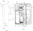
- FIGs. 1-4 illustrate a lock assembly 10, constructed and operative in accordance with a non-limiting embodiment of the present invention.
- Lock assembly 10 is described for a hasp lock but the invention is not limited to hasp locks.
- Hasp lock assembly 10 includes a first member 12 and a second member 14.
- the first member 12 houses a locking assembly that includes a locking bolt 16 that passes through a portion of second member 14 so as to lock the two members together.
- the members 12 and 14 and locking bolt 16 may be constructed of any suitable material, such as but not limited to, hardened steel alloy.
- the first and second members 12 and 14 include one or more complimentary shaped protrusions 13 and recesses 15 that mate with one another ( Fig. 4 ).
- the first and second members 12 and 14 also include one or more mechanical fasteners 11 ( Fig. 1 ) that protrude out the back of the case of the assembly for fastening the assembly to a door.
- Fig. 6 illustrates an optional back plate 42 of hasp lock assembly 10, which has different mounting provisions 44 for accommodating the mechanical fasteners (not shown in Fig. 6 ), and which has different mounting holes 46 for attaching the back plate 42 to the assembly 10.
- the locking assembly includes an electromechanical actuator 18, such as but not limited to, a servomotor, solenoid, gear motor, electromagnet and the like.
- Actuator 18 has a shaft 20, and a locking element 22 formed with a recess 24 is arranged to move along shaft 20 between a locked position and an unlocked position, as will be explained further below.
- Locking element 22 cooperates with a latch member 26, such as but not limited to, a locking ball.
- Shaft 20 may be threaded and rotatable by actuator 18, in which case locking element 22 may be complimentarily threaded such that rotation of shaft 20 causes locking element 22 to move linearly along shaft 20.
- Fig. 2 shows the locked position, in which actuator 18 has caused locking element 22 to move linearly along shaft 20 (downward in the sense of the drawing). In this position, latch member 26 is free to move and be received in recess 24 of locking element 22, thereby permitting movement of locking bolt 16 (downward in the sense of the drawing).
- Fig. 4 illustrates separation of first and second first members 12 and 14 after unlocking the assembly (for example, to permit opening a door to which the assembly is fastened).
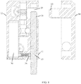
- a battery 30 powers actuator 18 and the locking bolt 16 must be removed in order to gain access to battery 30, as is now explained with reference to Figs. 4 and 5 .
- This feature provides security to prevent unauthorized persons from tampering with or stealing the battery.
- Battery 30 is retained inside a compartment 32 formed in first member 12.
- a battery retaining member 34 closes compartment 32, and is engageable with a battery locking member 36.
- Battery locking member 36 may include a spring-loaded pin engageable with battery retaining member 34. Specifically, in the illustrated embodiment, the spring-loaded pin enters a hole 38 ( Fig. 2 ) formed in battery retaining member 34 and abuts against the battery 30.
- locking bolt 16 locks battery locking member 36 and prevents movement of battery retaining member 34.
- Battery locking member 36 cannot move because it is sandwiched between battery retaining member 34 and a channel 39 ( Fig. 2 ) formed in locking bolt 16.
- Channel 39 serves as a stop when unlocking the assembly; that is, locking bolt 16 will not drop completely out of the assembly but instead will be retained in the unlocked assembly as seen in Fig. 3 because the battery locking member 36 abuts against the end of channel 39.
- first member 12 and locking bolt 16 are formed with a hasp aperture (through hole) 41 and a bolt aperture 43, respectively.
- locking bolt 16 is moved so that bolt aperture 43 is aligned with hasp aperture 41, as in Fig. 4 .
- a small tool such as a pin (not shown), can be inserted through apertures 41 and 43 to push against the spring-loaded pin of battery locking member 36. As seen in Fig. 5 , this permits removal of locking bolt 16 out of the assembly so as to permit removal of battery locking member 36 and of battery retaining member 34 to gain access to battery 30.
- a transceiver 40 ( Fig. 1 ) is in communication with actuator 18 for actuating actuator 18.
- Transceiver 40 may be any suitable transponder that works with wireless communication, such as but not limited to, infrared, BLUETOOTH, RF, cellular telephone communication, internet communication and so forth.
- wireless communication such as but not limited to, infrared, BLUETOOTH, RF, cellular telephone communication, internet communication and so forth.
- the hasp lock assembly 10 can be opened by remote communication, such as from a command center.
- a mechanical override may be provided, if desired.
Landscapes
- Lock And Its Accessories (AREA)
Description
- The present invention relates generally to high security locks and particularly to an electromechanical lock assembly.
- Padlocks that have protected hasps are known in the art and are referred herein as hasp locks. In a typical installation of a hasp lock, each side of a door opening (e.g., a hinged door and a jamb, or two sliding doors) is provided with a protective hasp for a lock body and shackle of a lock. Thus there are two hasp bodies which mate together when the doors are closed, and a shackle or locking pin locks the hasp bodies together.
- For example,
US Patent 7946142 to Matyko et al. describes a hasp lock, which includes a first member and a second member. The two members include complimentary shaped protrusions and recesses that mate with one another. A locking assembly is housed in the first member, including a cylinder lock that brings a locking element into locking engagement with a notch formed in a locking bolt. The locking bolt is arranged for sliding motion through a first bore formed in the first member. When the second member is aligned with the first member, the locking bolt is slidable into a second bore formed in the second member so as to lock the first and second members together. The locking element is movable into locking engagement with a second notch formed in the locking bolt so as to prevent moving the locking bolt completely out of the first member. -
WO-A-2012/102633 discloses a power assembly intended for the mechanical engagement of power elements of the lock; a means for locking the above-mentioned power assembly, which means is intended for adjusting the power assembly elements into a locked or unlocked position; a means for securing the positions of the above-mentioned locking means; an electromechanical means controlling displacement of the elements of the securing means upon commands from the electronic means for controlling the lock, wherein, in order to reduce power consumption by the electromechanical means, the locking means is displaced in the lock only with the aid of mechanical forces applied thereto by a user and/or by elements of the lock kinematically linked thereto, and the transition from locking to unlocking of the power assembly of the lock is achieved via an intermediate position of the locking means, in which the means for securing the positions of the locking means is relieved of the power load placed thereon by the locking means and, in said intermediate position, the electromechanical means displaces the unloaded securing means. - The present invention seeks to provide an improved electromechanical lock assembly, as described more in detail hereinbelow.
- It is noted that the term "door" as used throughout the specification and claims encompasses any kind of door, window, gate or panel, for example.
- The invention provides a lock assembly in accordance with claim 1.
- In accordance with an embodiment of the present invention the shaft is threaded and rotatable by the actuator, and the locking element is complimentarily threaded such that rotation of the shaft causes the locking element to move linearly along the shaft.
- In accordance with an embodiment of the present invention a battery powers the actuator. A battery retaining member is provided with a battery locking member engageable with the battery retaining member. In the locked position, the locking bolt locks the battery locking member and prevents movement of the battery retaining member. In the unlocked position, the locking bolt permits movement of the battery locking member and the battery retaining member to gain access to the battery.
- In accordance with an embodiment of the present invention the battery locking member includes a spring-loaded pin engageable with the battery retaining member.
- In accordance with an embodiment of the present invention a transceiver is in communication with the actuator for actuating the actuator.
- The present invention will be understood and appreciated more fully from the following detailed description taken in conjunction with the drawings in which:
-
Figs. 1 and 2 are simplified side-view and sectional illustrations of a lock assembly, constructed and operative in accordance with an embodiment of the present invention, withFig. 2 being taken along lines A-A inFig. 1 and showing a locking element in a locked position which prevents moving a locking bolt; -
Fig. 3 is a simplified sectional illustration of the lock assembly ofFig. 2 with the locking element in an unlocked position which allows moving a locking bolt to open the lock assembly; -
Fig. 4 is a simplified sectional illustration of the lock assembly, showing separation of the two halves of the lock assembly after unlocking the assembly; -
Fig. 5 is a simplified partial sectional illustration of the lock assembly, showing removal of the locking bolt to allow removal of the battery; and -
Fig. 6 is a simplified rear-view illustration of the lock assembly, showing a back plate which has different mounting provisions. - Reference is now made to
Figs. 1-4 , which illustrate alock assembly 10, constructed and operative in accordance with a non-limiting embodiment of the present invention.Lock assembly 10 is described for a hasp lock but the invention is not limited to hasp locks. -
Hasp lock assembly 10 includes afirst member 12 and asecond member 14. Thefirst member 12 houses a locking assembly that includes alocking bolt 16 that passes through a portion ofsecond member 14 so as to lock the two members together. Themembers bolt 16 may be constructed of any suitable material, such as but not limited to, hardened steel alloy. The first andsecond members shaped protrusions 13 and recesses 15 that mate with one another (Fig. 4 ). The first andsecond members Fig. 1 ) that protrude out the back of the case of the assembly for fastening the assembly to a door. -
Fig. 6 illustrates anoptional back plate 42 ofhasp lock assembly 10, which hasdifferent mounting provisions 44 for accommodating the mechanical fasteners (not shown inFig. 6 ), and which hasdifferent mounting holes 46 for attaching theback plate 42 to theassembly 10. - The locking assembly includes an
electromechanical actuator 18, such as but not limited to, a servomotor, solenoid, gear motor, electromagnet and the like.Actuator 18 has ashaft 20, and alocking element 22 formed with arecess 24 is arranged to move alongshaft 20 between a locked position and an unlocked position, as will be explained further below. Lockingelement 22 cooperates with alatch member 26, such as but not limited to, a locking ball.Shaft 20 may be threaded and rotatable byactuator 18, in whichcase locking element 22 may be complimentarily threaded such that rotation ofshaft 20 causeslocking element 22 to move linearly alongshaft 20. - In the locked position shown in
Fig. 2 , lockingbolt 16 passes through both first and secondfirst members latch member 26 is received in anotch 28 formed inlocking bolt 16. However, latch member is not received inrecess 24 oflocking element 22. In this manner,locking element 22 prevents movement of latch member 26 (the ball is sandwiched betweenlocking element 22 and lockingbolt 16 and cannot budge) and lockingbolt 16.Fig. 3 shows the unlocked position, in whichactuator 18 has causedlocking element 22 to move linearly along shaft 20 (downward in the sense of the drawing). In this position,latch member 26 is free to move and be received inrecess 24 oflocking element 22, thereby permitting movement of locking bolt 16 (downward in the sense of the drawing).Fig. 4 illustrates separation of first and secondfirst members - In accordance with an embodiment of the present invention a
battery 30powers actuator 18 and thelocking bolt 16 must be removed in order to gain access tobattery 30, as is now explained with reference toFigs. 4 and5 . This feature provides security to prevent unauthorized persons from tampering with or stealing the battery. -
Battery 30 is retained inside acompartment 32 formed infirst member 12. Abattery retaining member 34 closescompartment 32, and is engageable with abattery locking member 36.Battery locking member 36 may include a spring-loaded pin engageable withbattery retaining member 34. Specifically, in the illustrated embodiment, the spring-loaded pin enters a hole 38 (Fig. 2 ) formed inbattery retaining member 34 and abuts against thebattery 30. In the locked position, lockingbolt 16 locksbattery locking member 36 and prevents movement ofbattery retaining member 34.Battery locking member 36 cannot move because it is sandwiched betweenbattery retaining member 34 and a channel 39 (Fig. 2 ) formed inlocking bolt 16. Channel 39 serves as a stop when unlocking the assembly; that is, lockingbolt 16 will not drop completely out of the assembly but instead will be retained in the unlocked assembly as seen inFig. 3 because thebattery locking member 36 abuts against the end ofchannel 39. - It is noted that
first member 12 and lockingbolt 16 are formed with a hasp aperture (through hole) 41 and abolt aperture 43, respectively. In order to gain access tobattery 30 after unlocking thelocking bolt 16, instead of movinglocking bolt 16 to the end of its travel as inFig. 3 ,locking bolt 16 is moved so thatbolt aperture 43 is aligned withhasp aperture 41, as inFig. 4 . A small tool, such as a pin (not shown), can be inserted throughapertures battery locking member 36. As seen inFig. 5 , this permits removal oflocking bolt 16 out of the assembly so as to permit removal ofbattery locking member 36 and ofbattery retaining member 34 to gain access tobattery 30. - In accordance with an embodiment of the present invention a transceiver 40 (
Fig. 1 ) is in communication withactuator 18 for actuatingactuator 18.Transceiver 40 may be any suitable transponder that works with wireless communication, such as but not limited to, infrared, BLUETOOTH, RF, cellular telephone communication, internet communication and so forth. In this manner, thehasp lock assembly 10 can be opened by remote communication, such as from a command center. A mechanical override may be provided, if desired.
Claims (6)
- A lock assembly (10) comprising:a first member (12) and a second member (14) comprising one or more complimentary shaped protrusions (13) and recesses (15) that mate with one another; anda locking assembly housed in said first member (12), said locking assembly comprising an electromechanical actuator (18) with a shaft (20) and a locking element (22) arranged to move along said shaft (20) between a locked position and an unlocked position, said locking element (22) being formed with a recess (24);a latch member (26); anda locking bolt (16) formed with a notch (28), wherein in the locked position, said locking bolt (16) passes through both said first and second first members (12, 14) and said latch member (26) is received in said notch (28) but is not received in the recess (24) of the locking element (22) so that said locking element (22) prevents movement of said latch member (26) and said locking bolt (16), and in the unlocked position, said latch member (26) is received in said recess (24) of the locking element (22), thereby permitting movement of said locking bolt (16),wherein said first member (12) and said locking bolt (16) are formed with a hasp aperture (41) and a bolt aperture (43), respectively.
- The lock assembly (10) according to claim 1, wherein said shaft (20) is threaded and rotatable by said actuator (18), and said locking element (22) is complimentarily threaded such that rotation of said shaft (20) causes said locking element (22) to move linearly along said shaft (20).
- The lock assembly (10) according to claim 1 or claim 2, further comprising a battery to power said actuator (18).
- The lock assembly (10) according to claim 3, further comprising a battery retaining member (34) and a battery locking member (36) engageable with said battery retaining member (34), wherein in said locked position, said locking bolt (16) locks said battery locking member (36) and prevents movement of said battery retaining member (34), and in said unlocked position, said locking bolt (16) permits movement of said battery locking member (36) and said battery retaining member (34) to gain access to said battery.
- The lock assembly (10) according to claim 4, wherein said battery locking member (36) comprises a spring-loaded pin engageable with said battery retaining member (34).
- The lock assembly (10) according to any one of claims 1-5, further comprising a transceiver (40) in communication with said actuator (18) for actuating said actuator (18).
Priority Applications (4)
| Application Number | Priority Date | Filing Date | Title |
|---|---|---|---|
| RS20180282A RS56948B1 (en) | 2014-05-07 | 2015-04-29 | Electromechanical lock assembly |
| SI201530222T SI3140478T1 (en) | 2014-05-07 | 2015-04-29 | Electromechanical lock assembly |
| PL15728612T PL3140478T3 (en) | 2014-05-07 | 2015-04-29 | Electromechanical lock assembly |
| HRP20180625TT HRP20180625T1 (en) | 2014-05-07 | 2018-04-19 | Electromechanical lock assembly |
Applications Claiming Priority (2)
| Application Number | Priority Date | Filing Date | Title |
|---|---|---|---|
| IL232498A IL232498B (en) | 2014-05-07 | 2014-05-07 | Electromechanical lock assembly |
| PCT/IB2015/053103 WO2015170224A2 (en) | 2014-05-07 | 2015-04-29 | Electromechanical lock assembly |
Publications (2)
| Publication Number | Publication Date |
|---|---|
| EP3140478A2 EP3140478A2 (en) | 2017-03-15 |
| EP3140478B1 true EP3140478B1 (en) | 2018-01-24 |
Family
ID=51418226
Family Applications (1)
| Application Number | Title | Priority Date | Filing Date |
|---|---|---|---|
| EP15728612.1A Active EP3140478B1 (en) | 2014-05-07 | 2015-04-29 | Electromechanical lock assembly |
Country Status (19)
| Country | Link |
|---|---|
| US (1) | US10190338B2 (en) |
| EP (1) | EP3140478B1 (en) |
| CN (1) | CN106460412B (en) |
| AR (1) | AR100321A1 (en) |
| BR (1) | BR112016025778A2 (en) |
| CY (1) | CY1120388T1 (en) |
| DK (1) | DK3140478T3 (en) |
| ES (1) | ES2661589T3 (en) |
| HR (1) | HRP20180625T1 (en) |
| HU (1) | HUE038599T2 (en) |
| IL (1) | IL232498B (en) |
| LT (1) | LT3140478T (en) |
| NO (1) | NO3140478T3 (en) |
| PL (1) | PL3140478T3 (en) |
| PT (1) | PT3140478T (en) |
| RS (1) | RS56948B1 (en) |
| SI (1) | SI3140478T1 (en) |
| TW (1) | TWI652400B (en) |
| WO (1) | WO2015170224A2 (en) |
Families Citing this family (7)
| Publication number | Priority date | Publication date | Assignee | Title |
|---|---|---|---|---|
| SG11202012284VA (en) * | 2018-06-11 | 2021-01-28 | Loon Tech Pte Ltd | Electric drive mechanism for operating a lock |
| CN110242121B (en) * | 2018-10-09 | 2024-06-07 | 宁波生久科技有限公司 | Motor type snap lock |
| US10858864B2 (en) | 2018-11-09 | 2020-12-08 | Schlage Lock Company Llc | Motor-driven lock with roller |
| US11377873B2 (en) | 2019-03-12 | 2022-07-05 | Schlage Lock Company Llc | Electric latch mechanism |
| US11639617B1 (en) | 2019-04-03 | 2023-05-02 | The Chamberlain Group Llc | Access control system and method |
| US11933092B2 (en) | 2019-08-13 | 2024-03-19 | SimpliSafe, Inc. | Mounting assembly for door lock |
| CN112576140B (en) * | 2021-01-06 | 2022-01-07 | 宁波市欧佰胜箱柜制造有限公司 | Electronic drive self-locking safe |
Family Cites Families (9)
| Publication number | Priority date | Publication date | Assignee | Title |
|---|---|---|---|---|
| IL154441A0 (en) | 2003-02-13 | 2003-09-17 | Goldman Ilan | Padlock with solenoid |
| US6761051B1 (en) * | 2003-02-27 | 2004-07-13 | Ez Trend Technology Co., Ltd. | Electric padlock |
| US7076976B1 (en) * | 2005-04-11 | 2006-07-18 | Ilan Goldman | Inertial blocking mechanism |
| US6993943B1 (en) * | 2005-07-26 | 2006-02-07 | Ez Trend Technology Co., Ltd. | Electric Padlock |
| IL175231A (en) * | 2006-04-26 | 2010-05-31 | Mul T Lock Technologies Ltd | Padlock hasp assembly |
| WO2012102633A1 (en) * | 2011-01-24 | 2012-08-02 | Nunuparov Martyn Sergeevich | Electronic lock with a passive locking means |
| US8806907B2 (en) * | 2011-11-11 | 2014-08-19 | Master Lock Company Llc | Battery access and power supply arrangements |
| CN202866449U (en) * | 2012-08-28 | 2013-04-10 | 闵瑜 | Lockset device |
| TWM487339U (en) | 2014-02-25 | 2014-10-01 | Zheng-Han Zhan | Wireless controllable lock |
-
2014
- 2014-05-07 IL IL232498A patent/IL232498B/en active IP Right Grant
-
2015
- 2015-04-27 TW TW104113424A patent/TWI652400B/en not_active IP Right Cessation
- 2015-04-29 EP EP15728612.1A patent/EP3140478B1/en active Active
- 2015-04-29 BR BR112016025778A patent/BR112016025778A2/en active Search and Examination
- 2015-04-29 LT LTEP15728612.1T patent/LT3140478T/en unknown
- 2015-04-29 NO NO15728612A patent/NO3140478T3/no unknown
- 2015-04-29 DK DK15728612.1T patent/DK3140478T3/en active
- 2015-04-29 SI SI201530222T patent/SI3140478T1/en unknown
- 2015-04-29 WO PCT/IB2015/053103 patent/WO2015170224A2/en active Application Filing
- 2015-04-29 US US15/308,679 patent/US10190338B2/en not_active Expired - Fee Related
- 2015-04-29 ES ES15728612.1T patent/ES2661589T3/en active Active
- 2015-04-29 PL PL15728612T patent/PL3140478T3/en unknown
- 2015-04-29 RS RS20180282A patent/RS56948B1/en unknown
- 2015-04-29 CN CN201580023844.0A patent/CN106460412B/en not_active Expired - Fee Related
- 2015-04-29 HU HUE15728612A patent/HUE038599T2/en unknown
- 2015-04-29 PT PT157286121T patent/PT3140478T/en unknown
- 2015-05-06 AR ARP150101366A patent/AR100321A1/en active IP Right Grant
-
2018
- 2018-03-01 CY CY20181100261T patent/CY1120388T1/en unknown
- 2018-04-19 HR HRP20180625TT patent/HRP20180625T1/en unknown
Also Published As
| Publication number | Publication date |
|---|---|
| US10190338B2 (en) | 2019-01-29 |
| US20170204637A1 (en) | 2017-07-20 |
| CY1120388T1 (en) | 2019-07-10 |
| WO2015170224A2 (en) | 2015-11-12 |
| PT3140478T (en) | 2018-04-13 |
| ES2661589T3 (en) | 2018-04-02 |
| DK3140478T3 (en) | 2018-02-05 |
| HRP20180625T1 (en) | 2018-06-01 |
| TW201600696A (en) | 2016-01-01 |
| TWI652400B (en) | 2019-03-01 |
| HUE038599T2 (en) | 2018-10-29 |
| BR112016025778A2 (en) | 2017-08-15 |
| NO3140478T3 (en) | 2018-06-23 |
| IL232498B (en) | 2018-07-31 |
| IL232498A0 (en) | 2014-08-31 |
| AR100321A1 (en) | 2016-09-28 |
| EP3140478A2 (en) | 2017-03-15 |
| CN106460412B (en) | 2019-02-15 |
| RS56948B1 (en) | 2018-05-31 |
| SI3140478T1 (en) | 2018-05-31 |
| LT3140478T (en) | 2018-03-12 |
| PL3140478T3 (en) | 2018-07-31 |
| CN106460412A (en) | 2017-02-22 |
| WO2015170224A3 (en) | 2016-01-21 |
Similar Documents
| Publication | Publication Date | Title |
|---|---|---|
| EP3140478B1 (en) | Electromechanical lock assembly | |
| EP1907655B1 (en) | Security system for entrance barriers | |
| EP2971417B1 (en) | Interconnected locking system | |
| CN110536994B (en) | Reversible clutch mortise lock | |
| US8800329B1 (en) | Protected bar lock assembly | |
| US11898392B2 (en) | Hinge closure | |
| EP3589809B1 (en) | Locking module | |
| WO2007122609A1 (en) | Padlock hasp assembly | |
| US20170122003A1 (en) | Dead-latching slam bolt lock | |
| EP3385475B1 (en) | Anti-panic door closure | |
| DE19845515C2 (en) | Locking device for a lock | |
| EP3812538B1 (en) | Lock mechanism | |
| US11542726B2 (en) | Surface mounted single solenoid electric strike | |
| EP3262256B1 (en) | Universal lock with sliding stop mechanism | |
| CN206110904U (en) | Receive lever lock subassembly of protection | |
| GB2408773A (en) | Lock actuation mechanism comprising spring-loaded locking pin | |
| EP3461976B1 (en) | Improved door locking mechanism | |
| RU2257455C1 (en) | Method for door production, door, method for door leaf production, door leaf, method of locking system production (variants) and locking system for door (variants) | |
| GB2408774A (en) | Lock actuation mechanism comprising latch spindle mounted in cruciform aperture | |
| KR200412411Y1 (en) | Door duplication of the container the system which locks | |
| RU2257454C1 (en) | Method for door production, door, method for door leaf production, door leaf, method of locking system production and locking system for door | |
| EP1231343A3 (en) | Deadbolt type lock mechanism |
Legal Events
| Date | Code | Title | Description |
|---|---|---|---|
| STAA | Information on the status of an ep patent application or granted ep patent |
Free format text: STATUS: THE INTERNATIONAL PUBLICATION HAS BEEN MADE |
|
| PUAI | Public reference made under article 153(3) epc to a published international application that has entered the european phase |
Free format text: ORIGINAL CODE: 0009012 |
|
| STAA | Information on the status of an ep patent application or granted ep patent |
Free format text: STATUS: REQUEST FOR EXAMINATION WAS MADE |
|
| 17P | Request for examination filed |
Effective date: 20161102 |
|
| AK | Designated contracting states |
Kind code of ref document: A2 Designated state(s): AL AT BE BG CH CY CZ DE DK EE ES FI FR GB GR HR HU IE IS IT LI LT LU LV MC MK MT NL NO PL PT RO RS SE SI SK SM TR |
|
| AX | Request for extension of the european patent |
Extension state: BA ME |
|
| DAV | Request for validation of the european patent (deleted) | ||
| DAX | Request for extension of the european patent (deleted) | ||
| GRAP | Despatch of communication of intention to grant a patent |
Free format text: ORIGINAL CODE: EPIDOSNIGR1 |
|
| STAA | Information on the status of an ep patent application or granted ep patent |
Free format text: STATUS: GRANT OF PATENT IS INTENDED |
|
| INTG | Intention to grant announced |
Effective date: 20171031 |
|
| GRAS | Grant fee paid |
Free format text: ORIGINAL CODE: EPIDOSNIGR3 |
|
| GRAA | (expected) grant |
Free format text: ORIGINAL CODE: 0009210 |
|
| STAA | Information on the status of an ep patent application or granted ep patent |
Free format text: STATUS: THE PATENT HAS BEEN GRANTED |
|
| AK | Designated contracting states |
Kind code of ref document: B1 Designated state(s): AL AT BE BG CH CY CZ DE DK EE ES FI FR GB GR HR HU IE IS IT LI LT LU LV MC MK MT NL NO PL PT RO RS SE SI SK SM TR |
|
| REG | Reference to a national code |
Ref country code: GB Ref legal event code: FG4D |
|
| REG | Reference to a national code |
Ref country code: CH Ref legal event code: EP |
|
| REG | Reference to a national code |
Ref country code: DK Ref legal event code: T3 Effective date: 20180202 |
|
| REG | Reference to a national code |
Ref country code: AT Ref legal event code: REF Ref document number: 965887 Country of ref document: AT Kind code of ref document: T Effective date: 20180215 |
|
| REG | Reference to a national code |
Ref country code: IE Ref legal event code: FG4D |
|
| REG | Reference to a national code |
Ref country code: DE Ref legal event code: R096 Ref document number: 602015007613 Country of ref document: DE |
|
| REG | Reference to a national code |
Ref country code: NL Ref legal event code: FP |
|
| REG | Reference to a national code |
Ref country code: FR Ref legal event code: PLFP Year of fee payment: 4 |
|
| REG | Reference to a national code |
Ref country code: ES Ref legal event code: FG2A Ref document number: 2661589 Country of ref document: ES Kind code of ref document: T3 Effective date: 20180402 |
|
| REG | Reference to a national code |
Ref country code: SE Ref legal event code: TRGR |
|
| REG | Reference to a national code |
Ref country code: PT Ref legal event code: SC4A Ref document number: 3140478 Country of ref document: PT Date of ref document: 20180413 Kind code of ref document: T Free format text: AVAILABILITY OF NATIONAL TRANSLATION Effective date: 20180404 |
|
| REG | Reference to a national code |
Ref country code: EE Ref legal event code: FG4A Ref document number: E015113 Country of ref document: EE Effective date: 20180221 |
|
| REG | Reference to a national code |
Ref country code: RO Ref legal event code: EPE |
|
| REG | Reference to a national code |
Ref country code: HR Ref legal event code: TUEP Ref document number: P20180625 Country of ref document: HR |
|
| PGFP | Annual fee paid to national office [announced via postgrant information from national office to epo] |
Ref country code: MC Payment date: 20180328 Year of fee payment: 4 Ref country code: RS Payment date: 20180321 Year of fee payment: 4 |
|
| REG | Reference to a national code |
Ref country code: HR Ref legal event code: T1PR Ref document number: P20180625 Country of ref document: HR Ref country code: GR Ref legal event code: EP Ref document number: 20180400331 Country of ref document: GR Effective date: 20180518 |
|
| REG | Reference to a national code |
Ref country code: NO Ref legal event code: T2 Effective date: 20180124 |
|
| REG | Reference to a national code |
Ref country code: SK Ref legal event code: T3 Ref document number: E 26756 Country of ref document: SK |
|
| PGFP | Annual fee paid to national office [announced via postgrant information from national office to epo] |
Ref country code: PL Payment date: 20180410 Year of fee payment: 4 Ref country code: SI Payment date: 20180327 Year of fee payment: 4 Ref country code: RO Payment date: 20180327 Year of fee payment: 4 |
|
| REG | Reference to a national code |
Ref country code: DE Ref legal event code: R097 Ref document number: 602015007613 Country of ref document: DE |
|
| REG | Reference to a national code |
Ref country code: HU Ref legal event code: AG4A Ref document number: E038599 Country of ref document: HU |
|
| PGFP | Annual fee paid to national office [announced via postgrant information from national office to epo] |
Ref country code: AL Payment date: 20180426 Year of fee payment: 4 Ref country code: CY Payment date: 20180419 Year of fee payment: 4 |
|
| PLBE | No opposition filed within time limit |
Free format text: ORIGINAL CODE: 0009261 |
|
| STAA | Information on the status of an ep patent application or granted ep patent |
Free format text: STATUS: NO OPPOSITION FILED WITHIN TIME LIMIT |
|
| 26N | No opposition filed |
Effective date: 20181025 |
|
| PGFP | Annual fee paid to national office [announced via postgrant information from national office to epo] |
Ref country code: MK Payment date: 20180313 Year of fee payment: 4 |
|
| REG | Reference to a national code |
Ref country code: HR Ref legal event code: ODRP Ref document number: P20180625 Country of ref document: HR Payment date: 20190320 Year of fee payment: 5 |
|
| PGFP | Annual fee paid to national office [announced via postgrant information from national office to epo] |
Ref country code: GR Payment date: 20190314 Year of fee payment: 5 Ref country code: BE Payment date: 20190315 Year of fee payment: 5 Ref country code: EE Payment date: 20190326 Year of fee payment: 5 Ref country code: HR Payment date: 20190320 Year of fee payment: 5 |
|
| PGFP | Annual fee paid to national office [announced via postgrant information from national office to epo] |
Ref country code: PT Payment date: 20190416 Year of fee payment: 5 Ref country code: FI Payment date: 20190409 Year of fee payment: 5 Ref country code: ES Payment date: 20190503 Year of fee payment: 5 |
|
| PGFP | Annual fee paid to national office [announced via postgrant information from national office to epo] |
Ref country code: LV Payment date: 20190403 Year of fee payment: 5 |
|
| PG25 | Lapsed in a contracting state [announced via postgrant information from national office to epo] |
Ref country code: MC Free format text: LAPSE BECAUSE OF NON-PAYMENT OF DUE FEES Effective date: 20190430 |
|
| PG25 | Lapsed in a contracting state [announced via postgrant information from national office to epo] |
Ref country code: RO Free format text: LAPSE BECAUSE OF NON-PAYMENT OF DUE FEES Effective date: 20190429 Ref country code: BG Free format text: LAPSE BECAUSE OF NON-PAYMENT OF DUE FEES Effective date: 20191031 Ref country code: CY Free format text: LAPSE BECAUSE OF NON-PAYMENT OF DUE FEES Effective date: 20190429 |
|
| PG25 | Lapsed in a contracting state [announced via postgrant information from national office to epo] |
Ref country code: RS Free format text: LAPSE BECAUSE OF NON-PAYMENT OF DUE FEES Effective date: 20191114 Ref country code: SI Free format text: LAPSE BECAUSE OF NON-PAYMENT OF DUE FEES Effective date: 20190430 Ref country code: SM Free format text: LAPSE BECAUSE OF NON-PAYMENT OF DUE FEES Effective date: 20191107 |
|
| PGFP | Annual fee paid to national office [announced via postgrant information from national office to epo] |
Ref country code: MT Payment date: 20180429 Year of fee payment: 4 |
|
| PGFP | Annual fee paid to national office [announced via postgrant information from national office to epo] |
Ref country code: LT Payment date: 20200324 Year of fee payment: 6 |
|
| PGFP | Annual fee paid to national office [announced via postgrant information from national office to epo] |
Ref country code: CZ Payment date: 20200325 Year of fee payment: 6 Ref country code: SK Payment date: 20200326 Year of fee payment: 6 |
|
| PGFP | Annual fee paid to national office [announced via postgrant information from national office to epo] |
Ref country code: FR Payment date: 20200326 Year of fee payment: 6 |
|
| PGFP | Annual fee paid to national office [announced via postgrant information from national office to epo] |
Ref country code: DE Payment date: 20200415 Year of fee payment: 6 Ref country code: DK Payment date: 20200414 Year of fee payment: 6 Ref country code: NO Payment date: 20200414 Year of fee payment: 6 Ref country code: NL Payment date: 20200417 Year of fee payment: 6 Ref country code: IE Payment date: 20200409 Year of fee payment: 6 Ref country code: CH Payment date: 20200420 Year of fee payment: 6 Ref country code: TR Payment date: 20200429 Year of fee payment: 6 |
|
| PGFP | Annual fee paid to national office [announced via postgrant information from national office to epo] |
Ref country code: SE Payment date: 20200415 Year of fee payment: 6 Ref country code: GB Payment date: 20200422 Year of fee payment: 6 |
|
| REG | Reference to a national code |
Ref country code: HR Ref legal event code: PBON Ref document number: P20180625 Country of ref document: HR Effective date: 20200429 |
|
| REG | Reference to a national code |
Ref country code: EE Ref legal event code: MM4A Ref document number: E015113 Country of ref document: EE Effective date: 20200430 |
|
| REG | Reference to a national code |
Ref country code: FI Ref legal event code: MAE |
|
| PG25 | Lapsed in a contracting state [announced via postgrant information from national office to epo] |
Ref country code: AL Free format text: LAPSE BECAUSE OF NON-PAYMENT OF DUE FEES Effective date: 20190429 |
|
| PG25 | Lapsed in a contracting state [announced via postgrant information from national office to epo] |
Ref country code: PT Free format text: LAPSE BECAUSE OF NON-PAYMENT OF DUE FEES Effective date: 20201029 Ref country code: FI Free format text: LAPSE BECAUSE OF NON-PAYMENT OF DUE FEES Effective date: 20200429 Ref country code: LU Free format text: LAPSE BECAUSE OF NON-PAYMENT OF DUE FEES Effective date: 20200429 Ref country code: GR Free format text: LAPSE BECAUSE OF NON-PAYMENT OF DUE FEES Effective date: 20201109 Ref country code: EE Free format text: LAPSE BECAUSE OF NON-PAYMENT OF DUE FEES Effective date: 20200430 Ref country code: HU Free format text: LAPSE BECAUSE OF NON-PAYMENT OF DUE FEES Effective date: 20200430 Ref country code: HR Free format text: LAPSE BECAUSE OF NON-PAYMENT OF DUE FEES Effective date: 20200429 |
|
| REG | Reference to a national code |
Ref country code: BE Ref legal event code: MM Effective date: 20200430 |
|
| PG25 | Lapsed in a contracting state [announced via postgrant information from national office to epo] |
Ref country code: BE Free format text: LAPSE BECAUSE OF NON-PAYMENT OF DUE FEES Effective date: 20200430 Ref country code: LV Free format text: LAPSE BECAUSE OF NON-PAYMENT OF DUE FEES Effective date: 20200429 Ref country code: PL Free format text: LAPSE BECAUSE OF NON-PAYMENT OF DUE FEES Effective date: 20190429 |
|
| REG | Reference to a national code |
Ref country code: AT Ref legal event code: MM01 Ref document number: 965887 Country of ref document: AT Kind code of ref document: T Effective date: 20200429 |
|
| PG25 | Lapsed in a contracting state [announced via postgrant information from national office to epo] |
Ref country code: AT Free format text: LAPSE BECAUSE OF NON-PAYMENT OF DUE FEES Effective date: 20200429 |
|
| REG | Reference to a national code |
Ref country code: ES Ref legal event code: FD2A Effective date: 20210902 |
|
| PG25 | Lapsed in a contracting state [announced via postgrant information from national office to epo] |
Ref country code: IT Free format text: LAPSE BECAUSE OF NON-PAYMENT OF DUE FEES Effective date: 20200429 |
|
| REG | Reference to a national code |
Ref country code: DE Ref legal event code: R119 Ref document number: 602015007613 Country of ref document: DE |
|
| REG | Reference to a national code |
Ref country code: DK Ref legal event code: EBP Effective date: 20210430 |
|
| REG | Reference to a national code |
Ref country code: LT Ref legal event code: MM4D Effective date: 20210429 |
|
| REG | Reference to a national code |
Ref country code: NO Ref legal event code: MMEP |
|
| PG25 | Lapsed in a contracting state [announced via postgrant information from national office to epo] |
Ref country code: ES Free format text: LAPSE BECAUSE OF NON-PAYMENT OF DUE FEES Effective date: 20200430 |
|
| REG | Reference to a national code |
Ref country code: SE Ref legal event code: EUG |
|
| REG | Reference to a national code |
Ref country code: NL Ref legal event code: MM Effective date: 20210501 |
|
| REG | Reference to a national code |
Ref country code: SK Ref legal event code: MM4A Ref document number: E 26756 Country of ref document: SK Effective date: 20210429 |
|
| GBPC | Gb: european patent ceased through non-payment of renewal fee |
Effective date: 20210429 |
|
| REG | Reference to a national code |
Ref country code: AT Ref legal event code: UEP Ref document number: 965887 Country of ref document: AT Kind code of ref document: T Effective date: 20180124 |
|
| PG25 | Lapsed in a contracting state [announced via postgrant information from national office to epo] |
Ref country code: NO Free format text: LAPSE BECAUSE OF NON-PAYMENT OF DUE FEES Effective date: 20210430 Ref country code: MT Free format text: LAPSE BECAUSE OF FAILURE TO SUBMIT A TRANSLATION OF THE DESCRIPTION OR TO PAY THE FEE WITHIN THE PRESCRIBED TIME-LIMIT Effective date: 20190429 Ref country code: LI Free format text: LAPSE BECAUSE OF NON-PAYMENT OF DUE FEES Effective date: 20210430 Ref country code: LT Free format text: LAPSE BECAUSE OF NON-PAYMENT OF DUE FEES Effective date: 20210429 Ref country code: CH Free format text: LAPSE BECAUSE OF NON-PAYMENT OF DUE FEES Effective date: 20210430 Ref country code: SE Free format text: LAPSE BECAUSE OF NON-PAYMENT OF DUE FEES Effective date: 20210430 Ref country code: SK Free format text: LAPSE BECAUSE OF NON-PAYMENT OF DUE FEES Effective date: 20210429 Ref country code: FR Free format text: LAPSE BECAUSE OF NON-PAYMENT OF DUE FEES Effective date: 20210430 Ref country code: GB Free format text: LAPSE BECAUSE OF NON-PAYMENT OF DUE FEES Effective date: 20210429 Ref country code: CZ Free format text: LAPSE BECAUSE OF NON-PAYMENT OF DUE FEES Effective date: 20210429 Ref country code: DE Free format text: LAPSE BECAUSE OF NON-PAYMENT OF DUE FEES Effective date: 20211103 |
|
| PG25 | Lapsed in a contracting state [announced via postgrant information from national office to epo] |
Ref country code: NL Free format text: LAPSE BECAUSE OF NON-PAYMENT OF DUE FEES Effective date: 20210501 |
|
| PG25 | Lapsed in a contracting state [announced via postgrant information from national office to epo] |
Ref country code: IE Free format text: LAPSE BECAUSE OF NON-PAYMENT OF DUE FEES Effective date: 20210429 Ref country code: DK Free format text: LAPSE BECAUSE OF NON-PAYMENT OF DUE FEES Effective date: 20210430 |
|
| PG25 | Lapsed in a contracting state [announced via postgrant information from national office to epo] |
Ref country code: TR Free format text: LAPSE BECAUSE OF NON-PAYMENT OF DUE FEES Effective date: 20210429 |