EP3140216B1 - Carton and carton blank - Google Patents
Carton and carton blank Download PDFInfo
- Publication number
- EP3140216B1 EP3140216B1 EP15722845.3A EP15722845A EP3140216B1 EP 3140216 B1 EP3140216 B1 EP 3140216B1 EP 15722845 A EP15722845 A EP 15722845A EP 3140216 B1 EP3140216 B1 EP 3140216B1
- Authority
- EP
- European Patent Office
- Prior art keywords
- panel
- handle
- carton
- fold line
- handle panel
- Prior art date
- Legal status (The legal status is an assumption and is not a legal conclusion. Google has not performed a legal analysis and makes no representation as to the accuracy of the status listed.)
- Active
Links
Images


Classifications
-
- B—PERFORMING OPERATIONS; TRANSPORTING
- B65—CONVEYING; PACKING; STORING; HANDLING THIN OR FILAMENTARY MATERIAL
- B65D—CONTAINERS FOR STORAGE OR TRANSPORT OF ARTICLES OR MATERIALS, e.g. BAGS, BARRELS, BOTTLES, BOXES, CANS, CARTONS, CRATES, DRUMS, JARS, TANKS, HOPPERS, FORWARDING CONTAINERS; ACCESSORIES, CLOSURES, OR FITTINGS THEREFOR; PACKAGING ELEMENTS; PACKAGES
- B65D5/00—Rigid or semi-rigid containers of polygonal cross-section, e.g. boxes, cartons or trays, formed by folding or erecting one or more blanks made of paper
- B65D5/42—Details of containers or of foldable or erectable container blanks
- B65D5/44—Integral, inserted or attached portions forming internal or external fittings
- B65D5/46—Handles
- B65D5/46072—Handles integral with the container
- B65D5/46192—Handles integral with the container formed by incisions in the container or blank forming straps used as handles
-
- B—PERFORMING OPERATIONS; TRANSPORTING
- B65—CONVEYING; PACKING; STORING; HANDLING THIN OR FILAMENTARY MATERIAL
- B65D—CONTAINERS FOR STORAGE OR TRANSPORT OF ARTICLES OR MATERIALS, e.g. BAGS, BARRELS, BOTTLES, BOXES, CANS, CARTONS, CRATES, DRUMS, JARS, TANKS, HOPPERS, FORWARDING CONTAINERS; ACCESSORIES, CLOSURES, OR FITTINGS THEREFOR; PACKAGING ELEMENTS; PACKAGES
- B65D5/00—Rigid or semi-rigid containers of polygonal cross-section, e.g. boxes, cartons or trays, formed by folding or erecting one or more blanks made of paper
- B65D5/18—Rigid or semi-rigid containers of polygonal cross-section, e.g. boxes, cartons or trays, formed by folding or erecting one or more blanks made of paper by folding a single blank to U-shape to form the base of the container and opposite sides of the body portion, the remaining sides being formed primarily by extensions of one or more of these opposite sides, e.g. flaps hinged thereto
-
- B—PERFORMING OPERATIONS; TRANSPORTING
- B65—CONVEYING; PACKING; STORING; HANDLING THIN OR FILAMENTARY MATERIAL
- B65D—CONTAINERS FOR STORAGE OR TRANSPORT OF ARTICLES OR MATERIALS, e.g. BAGS, BARRELS, BOTTLES, BOXES, CANS, CARTONS, CRATES, DRUMS, JARS, TANKS, HOPPERS, FORWARDING CONTAINERS; ACCESSORIES, CLOSURES, OR FITTINGS THEREFOR; PACKAGING ELEMENTS; PACKAGES
- B65D71/00—Bundles of articles held together by packaging elements for convenience of storage or transport, e.g. portable segregating carrier for plural receptacles such as beer cans or pop bottles; Bales of material
- B65D71/06—Packaging elements holding or encircling completely or almost completely the bundle of articles, e.g. wrappers
- B65D71/12—Packaging elements holding or encircling completely or almost completely the bundle of articles, e.g. wrappers the packaging elements, e.g. wrappers being formed by folding a single blank
- B65D71/36—Packaging elements holding or encircling completely or almost completely the bundle of articles, e.g. wrappers the packaging elements, e.g. wrappers being formed by folding a single blank having a tubular shape, e.g. tubular wrappers, with end walls
-
- B—PERFORMING OPERATIONS; TRANSPORTING
- B65—CONVEYING; PACKING; STORING; HANDLING THIN OR FILAMENTARY MATERIAL
- B65D—CONTAINERS FOR STORAGE OR TRANSPORT OF ARTICLES OR MATERIALS, e.g. BAGS, BARRELS, BOTTLES, BOXES, CANS, CARTONS, CRATES, DRUMS, JARS, TANKS, HOPPERS, FORWARDING CONTAINERS; ACCESSORIES, CLOSURES, OR FITTINGS THEREFOR; PACKAGING ELEMENTS; PACKAGES
- B65D5/00—Rigid or semi-rigid containers of polygonal cross-section, e.g. boxes, cartons or trays, formed by folding or erecting one or more blanks made of paper
- B65D5/02—Rigid or semi-rigid containers of polygonal cross-section, e.g. boxes, cartons or trays, formed by folding or erecting one or more blanks made of paper by folding or erecting a single blank to form a tubular body with or without subsequent folding operations, or the addition of separate elements, to close the ends of the body
- B65D5/10—Rigid or semi-rigid containers of polygonal cross-section, e.g. boxes, cartons or trays, formed by folding or erecting one or more blanks made of paper by folding or erecting a single blank to form a tubular body with or without subsequent folding operations, or the addition of separate elements, to close the ends of the body with end closures formed by inward-folding of self-locking flaps hinged to tubular body
-
- B—PERFORMING OPERATIONS; TRANSPORTING
- B65—CONVEYING; PACKING; STORING; HANDLING THIN OR FILAMENTARY MATERIAL
- B65D—CONTAINERS FOR STORAGE OR TRANSPORT OF ARTICLES OR MATERIALS, e.g. BAGS, BARRELS, BOTTLES, BOXES, CANS, CARTONS, CRATES, DRUMS, JARS, TANKS, HOPPERS, FORWARDING CONTAINERS; ACCESSORIES, CLOSURES, OR FITTINGS THEREFOR; PACKAGING ELEMENTS; PACKAGES
- B65D5/00—Rigid or semi-rigid containers of polygonal cross-section, e.g. boxes, cartons or trays, formed by folding or erecting one or more blanks made of paper
- B65D5/42—Details of containers or of foldable or erectable container blanks
- B65D5/4266—Folding lines, score lines, crease lines
-
- B—PERFORMING OPERATIONS; TRANSPORTING
- B65—CONVEYING; PACKING; STORING; HANDLING THIN OR FILAMENTARY MATERIAL
- B65D—CONTAINERS FOR STORAGE OR TRANSPORT OF ARTICLES OR MATERIALS, e.g. BAGS, BARRELS, BOTTLES, BOXES, CANS, CARTONS, CRATES, DRUMS, JARS, TANKS, HOPPERS, FORWARDING CONTAINERS; ACCESSORIES, CLOSURES, OR FITTINGS THEREFOR; PACKAGING ELEMENTS; PACKAGES
- B65D5/00—Rigid or semi-rigid containers of polygonal cross-section, e.g. boxes, cartons or trays, formed by folding or erecting one or more blanks made of paper
- B65D5/42—Details of containers or of foldable or erectable container blanks
- B65D5/44—Integral, inserted or attached portions forming internal or external fittings
- B65D5/46—Handles
- B65D5/46072—Handles integral with the container
- B65D5/4612—Handles integral with the container formed by extensions of side flaps or by side flaps of a container formed by folding-up portions connected to a central panel from all sides
-
- B—PERFORMING OPERATIONS; TRANSPORTING
- B65—CONVEYING; PACKING; STORING; HANDLING THIN OR FILAMENTARY MATERIAL
- B65D—CONTAINERS FOR STORAGE OR TRANSPORT OF ARTICLES OR MATERIALS, e.g. BAGS, BARRELS, BOTTLES, BOXES, CANS, CARTONS, CRATES, DRUMS, JARS, TANKS, HOPPERS, FORWARDING CONTAINERS; ACCESSORIES, CLOSURES, OR FITTINGS THEREFOR; PACKAGING ELEMENTS; PACKAGES
- B65D2571/00—Bundles of articles held together by packaging elements for convenience of storage or transport, e.g. portable segregating carrier for plural receptacles such as beer cans, pop bottles; Bales of material
- B65D2571/00123—Bundling wrappers or trays
- B65D2571/00129—Wrapper locking means
- B65D2571/00135—Wrapper locking means integral with the wrapper
- B65D2571/00141—Wrapper locking means integral with the wrapper glued
-
- B—PERFORMING OPERATIONS; TRANSPORTING
- B65—CONVEYING; PACKING; STORING; HANDLING THIN OR FILAMENTARY MATERIAL
- B65D—CONTAINERS FOR STORAGE OR TRANSPORT OF ARTICLES OR MATERIALS, e.g. BAGS, BARRELS, BOTTLES, BOXES, CANS, CARTONS, CRATES, DRUMS, JARS, TANKS, HOPPERS, FORWARDING CONTAINERS; ACCESSORIES, CLOSURES, OR FITTINGS THEREFOR; PACKAGING ELEMENTS; PACKAGES
- B65D2571/00—Bundles of articles held together by packaging elements for convenience of storage or transport, e.g. portable segregating carrier for plural receptacles such as beer cans, pop bottles; Bales of material
- B65D2571/00123—Bundling wrappers or trays
- B65D2571/00432—Handles or suspending means
- B65D2571/00456—Handles or suspending means integral with the wrapper
- B65D2571/00462—Straps made by two slits in a wall
-
- B—PERFORMING OPERATIONS; TRANSPORTING
- B65—CONVEYING; PACKING; STORING; HANDLING THIN OR FILAMENTARY MATERIAL
- B65D—CONTAINERS FOR STORAGE OR TRANSPORT OF ARTICLES OR MATERIALS, e.g. BAGS, BARRELS, BOTTLES, BOXES, CANS, CARTONS, CRATES, DRUMS, JARS, TANKS, HOPPERS, FORWARDING CONTAINERS; ACCESSORIES, CLOSURES, OR FITTINGS THEREFOR; PACKAGING ELEMENTS; PACKAGES
- B65D2571/00—Bundles of articles held together by packaging elements for convenience of storage or transport, e.g. portable segregating carrier for plural receptacles such as beer cans, pop bottles; Bales of material
- B65D2571/00123—Bundling wrappers or trays
- B65D2571/00432—Handles or suspending means
- B65D2571/00456—Handles or suspending means integral with the wrapper
- B65D2571/00469—Straps made between two handholes
-
- B—PERFORMING OPERATIONS; TRANSPORTING
- B65—CONVEYING; PACKING; STORING; HANDLING THIN OR FILAMENTARY MATERIAL
- B65D—CONTAINERS FOR STORAGE OR TRANSPORT OF ARTICLES OR MATERIALS, e.g. BAGS, BARRELS, BOTTLES, BOXES, CANS, CARTONS, CRATES, DRUMS, JARS, TANKS, HOPPERS, FORWARDING CONTAINERS; ACCESSORIES, CLOSURES, OR FITTINGS THEREFOR; PACKAGING ELEMENTS; PACKAGES
- B65D2571/00—Bundles of articles held together by packaging elements for convenience of storage or transport, e.g. portable segregating carrier for plural receptacles such as beer cans, pop bottles; Bales of material
- B65D2571/00123—Bundling wrappers or trays
- B65D2571/00432—Handles or suspending means
- B65D2571/00518—Handles or suspending means with reinforcements
- B65D2571/00524—Handles or suspending means with reinforcements integral
-
- B—PERFORMING OPERATIONS; TRANSPORTING
- B65—CONVEYING; PACKING; STORING; HANDLING THIN OR FILAMENTARY MATERIAL
- B65D—CONTAINERS FOR STORAGE OR TRANSPORT OF ARTICLES OR MATERIALS, e.g. BAGS, BARRELS, BOTTLES, BOXES, CANS, CARTONS, CRATES, DRUMS, JARS, TANKS, HOPPERS, FORWARDING CONTAINERS; ACCESSORIES, CLOSURES, OR FITTINGS THEREFOR; PACKAGING ELEMENTS; PACKAGES
- B65D2571/00—Bundles of articles held together by packaging elements for convenience of storage or transport, e.g. portable segregating carrier for plural receptacles such as beer cans, pop bottles; Bales of material
- B65D2571/00123—Bundling wrappers or trays
- B65D2571/00432—Handles or suspending means
- B65D2571/00537—Handles or suspending means with stress relieving means
- B65D2571/00543—Handles or suspending means with stress relieving means consisting of cut-outs, slits, or the like
-
- B—PERFORMING OPERATIONS; TRANSPORTING
- B65—CONVEYING; PACKING; STORING; HANDLING THIN OR FILAMENTARY MATERIAL
- B65D—CONTAINERS FOR STORAGE OR TRANSPORT OF ARTICLES OR MATERIALS, e.g. BAGS, BARRELS, BOTTLES, BOXES, CANS, CARTONS, CRATES, DRUMS, JARS, TANKS, HOPPERS, FORWARDING CONTAINERS; ACCESSORIES, CLOSURES, OR FITTINGS THEREFOR; PACKAGING ELEMENTS; PACKAGES
- B65D2571/00—Bundles of articles held together by packaging elements for convenience of storage or transport, e.g. portable segregating carrier for plural receptacles such as beer cans, pop bottles; Bales of material
- B65D2571/00123—Bundling wrappers or trays
- B65D2571/00432—Handles or suspending means
- B65D2571/00537—Handles or suspending means with stress relieving means
- B65D2571/00549—Handles or suspending means with stress relieving means consisting of fold lines
-
- B—PERFORMING OPERATIONS; TRANSPORTING
- B65—CONVEYING; PACKING; STORING; HANDLING THIN OR FILAMENTARY MATERIAL
- B65D—CONTAINERS FOR STORAGE OR TRANSPORT OF ARTICLES OR MATERIALS, e.g. BAGS, BARRELS, BOTTLES, BOXES, CANS, CARTONS, CRATES, DRUMS, JARS, TANKS, HOPPERS, FORWARDING CONTAINERS; ACCESSORIES, CLOSURES, OR FITTINGS THEREFOR; PACKAGING ELEMENTS; PACKAGES
- B65D2571/00—Bundles of articles held together by packaging elements for convenience of storage or transport, e.g. portable segregating carrier for plural receptacles such as beer cans, pop bottles; Bales of material
- B65D2571/00123—Bundling wrappers or trays
- B65D2571/00555—Wrapper opening devices
-
- B—PERFORMING OPERATIONS; TRANSPORTING
- B65—CONVEYING; PACKING; STORING; HANDLING THIN OR FILAMENTARY MATERIAL
- B65D—CONTAINERS FOR STORAGE OR TRANSPORT OF ARTICLES OR MATERIALS, e.g. BAGS, BARRELS, BOTTLES, BOXES, CANS, CARTONS, CRATES, DRUMS, JARS, TANKS, HOPPERS, FORWARDING CONTAINERS; ACCESSORIES, CLOSURES, OR FITTINGS THEREFOR; PACKAGING ELEMENTS; PACKAGES
- B65D2571/00—Bundles of articles held together by packaging elements for convenience of storage or transport, e.g. portable segregating carrier for plural receptacles such as beer cans, pop bottles; Bales of material
- B65D2571/00123—Bundling wrappers or trays
- B65D2571/00648—Elements used to form the wrapper
- B65D2571/00654—Blanks
- B65D2571/0066—Blanks formed from one single sheet
-
- B—PERFORMING OPERATIONS; TRANSPORTING
- B65—CONVEYING; PACKING; STORING; HANDLING THIN OR FILAMENTARY MATERIAL
- B65D—CONTAINERS FOR STORAGE OR TRANSPORT OF ARTICLES OR MATERIALS, e.g. BAGS, BARRELS, BOTTLES, BOXES, CANS, CARTONS, CRATES, DRUMS, JARS, TANKS, HOPPERS, FORWARDING CONTAINERS; ACCESSORIES, CLOSURES, OR FITTINGS THEREFOR; PACKAGING ELEMENTS; PACKAGES
- B65D2571/00—Bundles of articles held together by packaging elements for convenience of storage or transport, e.g. portable segregating carrier for plural receptacles such as beer cans, pop bottles; Bales of material
- B65D2571/00123—Bundling wrappers or trays
- B65D2571/00709—Shape of the formed wrapper, i.e. shape of each formed element if the wrapper is made from more than one element
- B65D2571/00722—Shape of the formed wrapper, i.e. shape of each formed element if the wrapper is made from more than one element tubular with end walls, e.g. walls not extending on the whole end surface
- B65D2571/00728—Shape of the formed wrapper, i.e. shape of each formed element if the wrapper is made from more than one element tubular with end walls, e.g. walls not extending on the whole end surface the end walls being closed by gluing
Definitions
- the present invention relates to a carton and to a blank for forming the carton more specifically, but not exclusively, to a carton having a handle structure for carrying the carton.
- US 5,480,091 to Stout discloses a carton for packaging articles, and a blank for forming the carton, the carton includes a generally rectangular top wall having a pair of spaced hand apertures formed therein. The hand apertures are disposed to define therebetween a handle strip for use in lifting the carton.
- the top wall is provided with a fold line extending from the region of each corner of the top wall toward the handle strip and further with a first severance line extending transversely of each fold line. Each first severance line is interposed between the handle strip and the respective fold line such that each fold line terminates at the respective severance line. This arrangement prevents stress concentration at the region of the handle strip when the carton is lifted.
- US 6,131,803 to Oliff discloses a handle structure for a carton is formed within a panel having a strap member extending between end edges of the panel.
- An elongated web extends diagonally from an intersection of side and end edges of the panel.
- the elongated web includes a perforated line and a score line intermediate the perforated line and the end edge of the panel.
- a connecting tab lies intermediate the end region of the strap member and foldably interconnects the strap member with region of the panel that lies between the strap member and one of the side edges of the panel.
- the perforated line and score line of the elongated web intersect at a point distal the vertex of side and end edges.
- the present invention seeks to overcome or at least mitigate the problems of the prior art.
- a carton including a handle panel and a first corner panel.
- the handle panel has first and second opposing end edges and opposing side edges which intersect each other to form corners of the handle panel.
- the first corner panel is hinged to the handle panel at the first end edge.
- the handle panel includes a handle structure for carrying the carton.
- the handle structure includes a strap member integrally conjoined with the handle panel and extending substantially between the end edges of the handle panel.
- the strap member has opposing strap edges substantially disjoined from the handle panel.
- the strap member includes a substantially centrally disposed grip region.
- the handle structure further includes a severance line segment disposed proximate each corner of the handle panel respectively, and extending from a first end point proximate that corner to a second end point proximate the grip region of the strap member.
- the carton further include a first cutaway separating the first corner panel from a first one of the corners of the handle panel, and a second cutaway separating the first corner panel from a second one of the corners of the handle panel, such that when a force substantially normal to a plane of the handle panel is exerted upon the grip region, the first and second cutaways facilitate displacement of the first corner panel towards the first end edge of the handle panel whereby the strap member is encouraged to flex substantially outwardly of the plane to a biased position above the plane.
- the carton may further include a second corner panel hinged to the handle panel at the second end edge, a third cutaway separating the second corner panel from a third one of the corners of the handle panel, and a fourth cutaway separating the second corner panel from a fourth one of the corners of the handle panel, such that when a force substantially normal to the plane of the handle panel is exerted upon the grip region, the third and fourth cutaways facilitate displacement of the second corner panel towards the second end edge of the handle panel whereby the strap member is encouraged to flex substantially outwardly of the plane to said biased position.
- the grip region may be defined at least in part by respective segments of the opposing strap edges of the strap member, the respective segments being substantially parallel to the opposing side edges of the handle panel.
- the handle structure may further include a pair of first and second fold lines extending from each severance line segment and converging towards the adjacent corner of the handle panel.
- the carton may further comprise a first trapezoidal portion disposed adjacent to each corner of the handle panel.
- Each first trapezoidal portion may be defined in part by the respective pair of first and second fold lines.
- each first trapezoidal portion may be defined in part by the respective one of the first, second, third and fourth cutaways.
- an end edge of each first trapezoidal portions is defined by the respective one of the first, second, third and fourth cutaways.
- the carton may further include a second trapezoidal portion disposed between each severance line segment and the adjacent side edge of the handle panel.
- Each second trapezoidal portion may be disposed adjacent to the respective first trapezoidal portion and may be defined in part by a third fold line and the second fold line of the respective the first trapezoidal portion.
- the third and second fold lines of each second portion may extend divergently towards the adjacent side edge of the handle panel.
- the carton may further include a triangular portion disposed adjacent to each second trapezoidal portion.
- Each triangular portion may be defined in part by a fourth fold line and the third fold line of the respective second trapezoidal portion.
- the third and fourth fold lines of each triangular portion may extend divergently toward the adjacent side edge of the handle panel.
- the fourth fold line of each triangular portion may terminate on the third fold line of that triangular portion.
- a blank for forming a carton includes a plurality of panels for forming walls of the carton.
- the blank further includes a handle panel and a first corner panel.
- the handle panel forms one of the walls of the carton.
- the handle panel has first and second opposing end edges and opposing side edges that intersect to form corners of the handle panel.
- the first corner panel is hinged to the handle panel at the first end edge.
- the handle panel includes a handle structure for carrying the carton in a set up condition.
- the handle structure includes a strap member integrally conjoined with the handle panel and extending substantially between the end edges.
- the strap member has opposing strap edges substantially disjoined from the handle panel.
- the strap member includes a substantially centrally disposed grip region.
- the handle structure further includes a severance line segment disposed proximate each corner of the handle panel respectively, and extending from a first end point proximate the respective corner to a second end point proximate the grip region of the strap member.
- the blank further includes a first cutaway separating the first corner panel from a first one of the corners of the handle panel; and a second cutaway separating the first corner panel from a second one of the corners of the handle panel, such that in a set up carton when a force is exerted upon the grip region substantially normally to a plane of the handle panels, the first and second cutaways facilitate displacement of the first corner panel towards the first end edge of the handle panel to encourage the strap member to flex substantially outwardly of the plane to a biased position above the plane.
- the blank may further include a second corner panel hinged to the handle panel at the second end edge, a third cutaway separating the second corner panel from a third one of the corners of the handle panel, and a fourth cutaway separating the second corner panel from a fourth one of the corners of the handle panel, such that in a set up condition when a force substantially normal to the plane of the handle panel is exerted upon the grip region, the third and fourth cutaways facilitate displacement of the second corner panel towards the second end edge of the handle panel whereby the strap member is encouraged to flex substantially outwardly of the plane.
- each of the first, second, third and fourth cutaways is formed by an aperture.
- each aperture is defined in part by the handle panel, the respective corner panel, a side panel hinged to the handle panel, a minor end closure panel hinged to the corner panel and a web panel coupling the minor end closure panel to a major end closure panel hinged to the side panel.
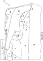
- Figure 1 shows a plan view of a first blank 10 capable of forming a carton 90, as shown in Figures 2 to 6 , for primary products such as, but not limited to, cans, hereinafter referred to as articles C.
- Figures 2 to 6 illustrate a carton 90 having a handle structure in accordance with a preferred embodiment of the invention.
- the terms “carton” and “carrier” refer, for the non-limiting purpose of illustrating the various features of the invention, to a container for engaging, carrying, and/or dispensing articles, such as product containers. It is contemplated that the teachings of the invention can be applied to various product containers, which may or may not be tapered and/or cylindrical. Exemplary containers include bottles (for example metallic, glass or plastics bottles), cans (for example aluminium cans), tins, pouches, packets and the like.
- suitable substrate includes all manner of foldable sheet material such as paperboard, corrugated board, cardboard, plastic, combinations thereof, and the like. It should be recognized that one or other numbers of blanks may be employed, where suitable, for example, to provide the carrier structure described in more detail below.
- the blanks are configured to form a carton or carrier for packaging an exemplary arrangement of exemplary articles.
- the arrangement is a 3 x 5 matrix or array and the articles are cans.
- the blank can be alternatively configured to form a carrier for packaging other types, number and size of article and/or for packaging articles in a different arrangement or configuration.
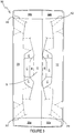
- Figures 2 and 3 illustrate the transverse alignment of cans C with respect to the handle structure H of the carton 90 in accordance with a preferred embodiment of the invention.
- Figures 5 and 6 depict the manner in which the top wall of the carton 90, including its handle structure, bows upwardly when a force F is applied to lift a strap member S by a user U.
- the blank 10 comprises a plurality of main panels 12, 14, 16, 18, 20 hinged one to the next in a linear series.
- the first blank 10 comprises a first top panel 12 hinged to a first side panel 14 by a fold line 11.
- the first side panel 14 is hinged to a base panel 16 by a fold line 13.
- the base panel 16 is hinged to a second side panel 18 by a fold line 15.
- the second panel 18 is hinged to a second top panel 20 by a fold line 17.
- the plurality of main panels 12, 14, 16, 18, 20 of the first blank 10 forms an open ended tubular structure when in a set up condition.
- Each of the ends of the tubular structure is at least partially closed by end closure panels.
- the ends of the tubular structure are fully closed by end closure panels 22a, 24a, 26a, 28a, 30a, 22b, 24b, 26b, 28b, 30b.
- End closure panels 22a, 24a, 26a, 28a, 30a are configured to close a first end of the tubular structure and end panels 22b, 24b, 26b, 28b, 30b are configured to close a second end of the tubular structure.
- a first end closure panel 22a is hinged to a first end of the first top panel 12 by a pair of fold lines 21a, 21b.
- a second end closure panel 24a is hinged to a first end of the first side panel 14 by a fold line 23a.
- a third end closure panel 26a is hinged to a first end of base panel 16 by a pair of fold lines 25a, 25b.
- a fourth end closure panel 28a is hinged to a first end of the second side panel 18 by a fold line 27a.
- a fifth end closure panel 30a is hinged to a first end of second top panel 20 by a pair of fold lines 29a, 29b.
- the pair of fold lines 21a, 21b define a first corner panel or bevel panel 32a disposed between the first top panel 12 and the first end closure panel 22a.
- the pair of fold lines 29a, 29b define a second corner panel or bevel panel 36a disposed between the second top panel 20 and the fifth end closure panel 30a. Together the first corner panel 32a and the second corner panel 36a form a composite corner panel 32a/36a at a first upper end of the carton 90.
- the pair of fold lines 25a, 25b define a third corner panel 34a disposed between the base panel 16 and the third end closure panel 26a.
- a sixth end closure panel 22b is hinged to a second end of the first top panel 12 by a pair of fold lines 21c, 21d.
- a seventh end closure panel 24b is hinged to a second end of first side panel 14 by a fold line 23b.
- An eighth end closure panel 26b is hinged to a second end of base panel 16 by a pair of fold lines 25c, 25d.
- a ninth end closure panel 28b is hinged to a second end of second side panel 18 by a fold line 27b.
- a tenth end closure panel 30b is hinged to a second end of second top panel 20 by a pair of fold lines 29c, 29d.
- the pair of fold lines 21c, 21d define a fourth corner panel 32b disposed between the first top panel 12 and the sixth end closure panel 22b.
- the pair of fold lines 29c, 29d define a fifth corner panel 36b disposed between the second top panel 20 and the tenth end closure panel 30b. Together the fourth corner panel 32b and the fifth corner panel 36b form a composite corner panel 32b/36b at a second upper end of the carton 90.
- the pair of fold lines 25c, 25d define a sixth corner panel 34b disposed between the base panel 16 and the eighth end closure panel 26b.
- the first end closure panel 22a and the fifth end closure panel 30a together form a minor side end closure panel.
- the third end closure panel 26a forms a minor side end closure panel.
- the sixth end closure panel 22b and the tenth end closure panel 30b together form a minor side end closure panel.
- the eighth end closure panel 26b forms a minor side end closure panel.
- the second end closure panel 24a and the fourth end closure panel 28a each form a major upper end closure panel.
- the seventh end closure panel 24b and the ninth end closure panel 28b each form a major lower end closure panel.
- a first web panel 38a couples the first end closure panel 22a to the second end closure panel 24a.
- the first web panel 38a is hinged to the first end closure panel 22a by a fold line 39a.
- the first web panel 38a is hinged to the second end closure panel 24a by a fold line 41a.
- a second web panel 40a couples the second end closure panel 24a to the third end closure panel 26a.
- the second web panel 40a is hinged to the second end closure panel 24a by a fold line 43a.
- the second web panel 40a is hinged to the third end closure panel 26a by a fold line 45a.
- a third web panel 42a couples the third end closure panel 26a to the fourth end closure panel 28a.
- the third web panel 42a is hinged to the third end closure panel 26a by a fold line 47a.
- the third web panel 42a is hinged to the fourth end closure panel 28a by a fold line 49a.
- a fourth web panel 44a couples the fourth end closure panel 28a to the fifth end closure panel 30a.
- the fourth web panel 44a is hinged to the fourth end closure panel 28a by a fold line 51a.
- the fourth web panel 44a is hinged to the fifth end closure panel 30a by a fold line 53a.
- a fifth web panel 38b couples the sixth end closure panel 22b to the seventh end closure panel 24b.
- the fifth web panel 38b is hinged to the sixth end closure panel 22b by a fold line 39b.
- the fifth web panel 38b is hinged to the seventh end closure panel 24b by a fold line 41b.
- a sixth web panel 40b couples the seventh end closure panel 24b to the eighth end closure panel 26b.
- the sixth web panel 40b is hinged to the seventh end closure panel 24b by a fold line 43b.
- the sixth web panel 40b is hinged to the eighth end closure panel 26b by a fold line 45b.
- a seventh web panel 42b couples the eighth end closure panel 26b to the ninth end closure panel 28b.
- the seventh web panel 42b is hinged to the eighth end closure panel 26b by a fold line 47b.
- the seventh web panel 42b is hinged to the ninth end closure panel 28b by a fold line 49b.
- An eighth web panel 44b couples the ninth end closure panel 28b to the tenth end closure panel 30b.
- the eighth web panel 44b is hinged to the ninth end closure panel 28b by a fold line 51b.
- the eighth web panel 44b is hinged to the tenth end closure panel 30b by a fold line 53b.
- the blank 10 comprises a first aperture A1, first aperture A1 is defined in part by the first top panel 12, the first side panel 14, the first corner panel 32a, the first end closure panel 22a, the first web panel 38a and the second end closure panel 24a.
- the blank 10 comprises a second aperture A2, second aperture A2 is defined in part by the first top panel 12, the first side panel 14, the fourth corner panel 32b, the sixth end closure panel 22b, the fifth web panel 38b and the seventh end closure panel 24b.
- the blank 10 comprises a third aperture A3, third aperture A3 is defined in part by the base panel 16, the first side panel 14, the third corner panel 34a, the third end closure panel 26a, the second web panel 40a and the second end closure panel 24a.
- the blank 10 comprises a fourth aperture A4, fourth aperture A4 is defined in part by the base panel 16, the first side panel 14, the sixth corner panel 34b, the eighth end closure panel 26b, the sixth web panel 40b and the seventh end closure panel 24b.
- the blank 10 comprises a fifth aperture A5, fifth aperture A5 is defined in part by the base panel 16, the second side panel 18, the third corner panel 34a, the third end closure panel 26a, the third web panel 42a and the fourth end closure panel 28a.
- the blank 10 comprises a sixth aperture A6, sixth aperture A6 is defined in part by the base panel 16, the second side panel 18, the sixth corner panel 34b, the eighth end closure panel 26b, the seventh web panel 42b and the ninth end closure panel 28b.
- the blank 10 comprises a seventh aperture A7 seventh aperture A7 is defined in part by the second top panel 20, the second side panel 18, the second corner panel 36a, the fifth end closure panel 30a, the fourth web panel 44a and the fourth end closure panel 28a.
- the blank 10 comprises an eighth aperture A8, eighth aperture A8 is defined in part by the second top panel 20, the second side panel 18, the fifth corner panel 36b, the tenth end closure panel 30b, the sixth web panel 44b and the ninth end closure panel 28b.
- the blank 10 comprises a first handle structure HA1 in the first top panel 12 and a second handle structure HA2 in the second top panel 20.
- the blank 10 comprises an access device struck in part from the base panel 16 and in part from the second side panel 18.
- the access device 50 comprises a gate panel 52.
- the gate panel 52 is defined by a first severance line 54a, a second severance line 54b, a third severance line 54c and a tear initiation device 50.
- the gate panel 52 is hinged to the carton 90, for example by a hinge line, in replacement of a second severance line 54b.
- the second severance line 54b is defined in the second side panel 18.
- the first severance line 54a extends from a first end of the second severance line 54b into the base panel 16 to a first end of the tear initiation device 50.
- the third severance line 54c extends from a second end of the second severance line 54b into the base panel 16 to a second end of the tear initiation device 50.
- first severance line 54a, the second severance line 54b, the third severance line 54c and the tear initiation device 50 form a continuous loop.
- the tear initiation device 50 comprises pair of tabs 56a, 56b defined by a substantially “m” shaped severance line 58 and a pair of fold lines 59a, 59b.
- the "m” shaped severance line 58 extends between a second end of the first severance line 54a and a second end of the third severance line 54c.
- a first fold line 59a extends from a first end of the "m” shaped severance line 58 to the centre of the "m” shaped severance line 58.
- a second fold line 59b extends from a second end of the "m” shaped severance line 58 to the centre of the "m” shaped severance line 58. In this way two tabs 56a, 56b are formed which are hinged to the gate panel 52.
- tabs 56a, 56b may be hinged to the base panel 16.
- the blank 10 comprises a handle structure; the handle structure is defined in part in the first top panel 12 and in part in the second top panel 20.
- the first top panel 12 and the second top panel 20 form the top wall, or panel, of the carton 90 that contains the handle structure.
- the first top panel 12 comprises a first portion H1 of the handle structure.
- the first portion H1 comprises a strap member with a tapered region mediate each of the end regions.
- the strap member is defined at least in part by a first handle aperture HA1 and a first severance line 61a, and a second severance line 63a.
- the handle structure comprises a cushioning flap 6 hinged to the strap member by a fold line 7, the cushioning flap 6 being defined at least in part by the first handle aperture HA1.
- a web extends diagonally from the vertex of a side edge and an end edge of the first top panel 12.
- a first web disposed at a first end of the strap member, comprises a plurality of fold lines 79a, 77a, 75a, 73a and a third severance line 65a.
- the third severance line 65a extends substantially longitudinally with respect to the first top panel 12.
- the third severance line 65a is spaced apart from the first severance line 61a.
- the third severance line 65a is arranged in a partially overlapping relationship with the first severance line 61a.
- a connecting member 62a is defined in the region of the overlap between the third severance line 65a and the first severance line 61a.
- the connecting member 62a conjoins the strap member and a portion of the region of the first top panel 12 adjacent the strap member.
- the connecting member 62a is defined in part by a fold line 93a and a fold line 95a.
- Fold line 95a extends between the third severance line 65a and the first severance line 61a.
- Fold line 93a extends between the third severance line 65a and the first handle aperture HA1.
- the web comprises a first fold line 79a, first fold line 79a extends between an end of the third severance line 65a and a first end edge of the first top panel 12 defined by the fold line 21a.
- the first fold line 79a terminates at the first aperture A1 at a point inset laterally from the side edge of the first top panel 12 defined by the fold line 11.
- the first web comprises a second fold line 77a, second fold line 77a extends between the third severance line 65a and a first corner of the first top panel 12 defined by the first end edge (fold line 21a) and the side edge (fold line 11).
- the second fold line 77a terminates at the first aperture A1 at a point on the side edge of the first top panel 12.
- the first fold line 79a and the second fold line 77a define in part a first trapezoidal portion of the first top panel 12.
- the first fold line 79a and the second fold line 77a are arranged to be convergent towards the first corner of the top panel 12.
- the first web comprises a third fold line 75a, third fold line 75a extends between the third severance line 65a and a side edge of the first top panel 12 defined by the fold line 11 at a point inset longitudinally from the first corner of the top panel 12.
- the third fold line 75a and the second fold line 77a define in part a second trapezoidal portion of the first top panel 12.
- the third fold line 75a and the second fold line 77a are arranged to be convergent towards the third severance line 65a.
- the first web comprises a fourth fold line 73a, fourth fold line 73a extends between the third fold line 75a and a side edge of the first top panel 12 defined by the fold line 11 at a point inset longitudinally from the terminus of the third fold line 75a on the fold line 11.
- the third fold line 75a and the fourth fold line 73a define in part a triangular portion of the first top panel 12.
- the first aperture A1 is substantially “boot” shaped, the “toe” of the “boot” extending into the first corner panel 32a, and the “shaft” of the “boot” extending substantially longitudinally.
- the “heel” of the “boot” lies substantially on the fold line 11 defining the side edge of the first top panel 12.
- a second web disposed at a second end of the strap member, comprises a plurality of fold lines 81a, 83a, 85a, 87a and a fourth severance line 67a.
- the fourth severance line 67a extends substantially longitudinally with respect to the first top panel 12.
- the fourth severance line 67a is spaced apart from the second severance line 63a.
- the fourth severance line 67a is arranged in a partial overlapping relationship with the second severance line 63a.
- a connecting member 64a is defined in the region of the overlap between the fourth severance line 67a and the second severance line 63a.
- the connecting member 64a conjoins the strap member and a portion of the region of the first top panel 12 adjacent the strap member.
- the connecting member 64a is defined in part by a fold line 89a and a fold line 91a.
- Fold line 89a extends between the fourth severance line 67a and the second severance line 63a.
- Fold line 91a extends between the fourth severance line 67a and the first handle aperture HA1.
- the second web comprises a first fold line 81a, first fold line 81a extends between an end of the fourth severance line 67a and a second end edge of the first top panel 12 defined by the fold line 21c.
- the first fold line 81a terminates at the second aperture A2 at point inset laterally from the side edge of the first top panel 12 defined by the fold line 11.
- the second web comprises a second fold line 83a, second fold line 83a extends between the fourth severance line 67a to a second corner of the first top panel 12 defined by the second end edge (fold line 21c) and the side edge (fold line 11).
- the second fold line 83a terminates at the second aperture A2 at point on the side edge of the first top panel 12.
- the first fold line 81a and the second fold line 83a define in part a first trapezoidal portion of the first top panel 12.
- the first fold line 81a and the second fold line 83a are arranged to be convergent towards the second corner of the top panel 12.
- the second web comprises a third fold line 85a, third fold line 85a extends between the fourth severance line 67a and a side edge of the first top panel 12 defined by the fold line 11 at a point inset longitudinally from the second corner of the top panel 12.
- the third fold line 85a and the second fold line 83a define in part a second trapezoidal portion of the first top panel 12.
- the third fold line 85a and the second fold line 83a are arranged to be convergent towards the fourth severance line 67a.
- the second web comprises a fourth fold line 87a, fourth fold line 87a extends between the third fold line 85a and a side edge of the first top panel 12 defined by the fold line 11 at a point inset longitudinally from the terminus of the third fold line 85a on the fold line 11.
- the third fold line 85a and the fourth fold line 87a define in part a triangular portion of the first top panel 12.
- the second aperture A2 is substantially “boot” shaped, the “toe” of the “boot” extending into the fourth corner panel 32b, and the “shaft” of the “boot” extending substantially longitudinally.
- the “heel” of the “boot” lies substantially on the fold line 11 defining the side edge of the first top panel 12.
- the second top panel 20 comprises a second portion H2 of the handle structure, the second portion H2 comprises a strap member with a tapered region mediate each of the end regions.
- the strap member is defined at least in part by a second handle aperture HA2 and a first severance line 61b and a second severance line 63b.
- the handle structure comprises a cushioning flap 8 hinged to the strap member by a fold line 9, the cushioning flap 8 being defined at least in part by the second handle aperture HA2.
- a web extends diagonally from the vertex of a side edge and an end edge of the second top panel 20.
- a first web disposed at a first end of the strap member, comprises a plurality of fold lines 79b, 77b, 75b, 73b and a third severance line 65b.
- the third severance line 65b extends substantially longitudinally with respect to the second top panel 20.
- the third severance line 65b is spaced apart from the first severance line 61b.
- the third severance line 65b is arranged in a partial overlapping relationship with from the first severance line 61b.
- a connecting member 62b is defined in the region of the overlap between the third severance line 65b and the first severance line 61b.
- the connecting member 62b conjoins the strap member and a portion of the region of the second top panel 20 adjacent the strap member.
- the connecting member 62b is defined in part by a fold line 93b and a fold line 95b.
- Fold line 95b extends between the third severance line 65b and the first severance line 61b.
- Fold line 93b extends between the third severance line 65b and the second handle aperture HA2.
- the web comprises a first fold line 79b, first fold line 79b extends between an end of the third severance line 65b and a first end edge of the second top panel 20 defined by the fold line 29a.
- the first fold line 79b terminates at the seventh aperture A7 at point inset laterally from the side edge of the second top panel 20 defined by the fold line 17.
- the first web comprises a second fold line 77b.
- Second fold line 77b extends between the third severance line 65b to a first corner of the second top panel 20 defined by the first end edge (fold line 29a) and the side edge (fold line 17).
- the second fold line 77b terminates at the seventh aperture A7 at point on the side edge of the second top panel 20.
- the first fold line 79b and the second fold line 77b define in part a first trapezoidal portion of the second top panel 20.
- the first fold line 79b and the second fold line 77b are arranged to be convergent towards the first corner of the second top panel 20.
- the first web comprises a third fold line 75b, third fold line 75b extends between the third severance line 65b and a side edge of the second top panel 20 defined by the fold line 17 at a point inset longitudinally from the first corner of the second top panel 20.
- the third fold line 75b and the second fold line 77b define in part a second trapezoidal portion of the second top panel 20.
- the third fold line 75b and the second fold line 77b are arranged to be convergent towards the third severance line 65b.
- the first web comprises a fourth fold line 73b, fourth fold line 73b extends between the third fold line 75b and a side edge of the second top panel 20 defined by the fold line 17 at a point inset longitudinally from the terminus of the third fold line 75b on the fold line 17.
- the third fold line 75b and the fourth fold line 73b define in part a triangular portion of the second top panel 20.
- the seventh aperture A7 is substantially “boot” shaped, the “toe” of the “boot” extending into the second corner panel 36a, and the “shaft” of the “boot” extending substantially longitudinally.
- the “heel” of the “boot” lies substantially on the fold line 17 defining the side edge of the second top panel 20.
- a second web disposed at a second end of the strap member, comprises a plurality of fold lines 81b, 83b, 85b, 87b and a fourth severance line 67b.
- the fourth severance line 67b extends substantially longitudinally with respect to the second top panel 20.
- the fourth severance line 67b is spaced apart from the second severance line 63b.
- the fourth severance line 67b is arranged in a partial overlapping relationship with from the second severance line 63b.
- a connecting member 64b is defined in the region of the overlap between the fourth severance line 67b and the second severance line 63b.
- the connecting member 64b conjoins the strap member and a portion of the region of the second top panel 20 adjacent the strap member.
- the connecting member 64b is defined in part by a fold line 89b and a fold line 91b.
- Fold line 89b extends between the fourth severance line 67b and the second severance line 63b.
- Fold line 91b extends between the fourth severance line 67b and the second handle aperture HA2.
- the second web comprises a first fold line 81b, first fold line 81b extends between an end of the fourth severance line 67b and a second end edge of the second top panel 20 defined by the fold line 29c.
- the first fold line 81b terminates at the eighth aperture A8 at point inset laterally from the side edge of the second top panel 20 defined by the fold line 17.
- the second web comprises a second fold line 83b, second fold line 83b extends between the fourth severance line 67b to a second corner of the second top panel 20 defined by the second end edge (fold line 29c) and the side edge (fold line 17).
- the second fold line 83b terminates at the eighth aperture A8 at point on the side edge of the second top panel 20.
- the first fold line 81b and the second fold line 83b define in part a first trapezoidal portion T1 of the second top panel 20.
- the first fold line 81b and the second fold line 83b are arranged to be convergent towards the second corner of the second top panel 20.
- the second web comprises a third fold line 85b, third fold line 85b extends between the fourth severance line 67b and a side edge of the second top panel 20 defined by the fold line 17 at a point inset longitudinally from the second corner of the second top panel 20.
- the third fold line 85b and the second fold line 83b define in part a second trapezoidal portion T2 of the second top panel 20.
- the third fold line 85b and the second fold line 83b are arranged to be convergent towards the fourth severance line 67b.
- the second web comprises a fourth fold line 87b, fourth fold line 87b extends between the third fold line 85b and a side edge of the second top panel 20 defined by the fold line 17 at a point inset longitudinally from the terminus of the third fold line 85b on the fold line 17.
- the third fold line 85b and the fourth fold line 87b define in part a triangular portion T3 of the second top panel 20.
- the eighth aperture A8 is substantially “boot” shaped, the “toe” of the “boot” extending into the fifth corner panel 36b, and the “shaft” of the “boot” extending substantially longitudinally.
- the “heel” of the “boot” lies substantially on the fold line 17 defining the side edge of the second top panel 20.
- the strap member of the first top panel 12 and the strap member of the second top panel 20 overlap, at least partially, and the tapered regions overlap at least partially, to produce a substantially reinforced handle.
- the strap member S of the carrying handle H provides a structure that directs stress towards the ends of the carton 90.
- the features of the handle structure which are described above cause the strap S and other elements upon the composite top panel 12/20 of the carton 90 to flex, or bow, in an outwardly-projecting predetermined manner when the carton 90 is lifted F by a user U, as shown in Figures 5 and 6 .
- the structure of the webs causes the composite top panel 12/20 of the carton 90 to concavely bow in a stepped configuration, ascending inwardly, when the carton is lifted by a force, as illustrated in Figure 6 .
- the connecting tabs 62a, 62b, 64a, 64b interconnect the strap S and adjacent regions of the composite top panel 12/20.
- This interconnection causes the composite top panel 12/20 to maintain a more contiguous configuration when the carton 90 is lifted.
- the side regions of the composite top panel 12/20 have a tendency to flex away from the strap S.
- the connecting tabs 62a, 62b, 64a, 64b inhibit such movement and promote a more pleasing appearance and greater integrity of the composite top panel 12/20.
- corner panels 32a, 32b, 34a, 34b, 36a, 36b enable the corners of the carton 90 to be drawn tighter when cans C or similar articles are transversely aligned in the carton 90 with respect to the lengthwise dimension of the carton 90 and composite top panel 12/20, as shown in Figures 5 and 6 .
- the first aperture A1, second aperture A2, seventh aperture A7 and eighth aperture A8 facilitate the inward movement of the corner panels 32a, 32b, 36a, 36b.
- first aperture A1, second aperture A2, seventh aperture A7 and eighth aperture A8 each close up as can be seen by comparison of Figure 6 to Figure 4 . In this way the ends of the handle structure are braced upon the endmost articles in the uppermost row of the carton 90.
- the structure of the invention provides a handle that is reinforced and that directs stress away from the handle itself to the ends of the carton while helping the carton to maintain an aesthetically pleasing appearance and greater integrity when lifted.
- each of the first, second, seventh and eighth apertures A1, A2, A7, A8 forms a cutaway between the end portions of the first, second, fourth and fifth corner panels 32a, 32b, 36a, 36b and the handle panel formed by the composite top panel 12/20.
- the cutaway may be formed from a slit or slot.
- the carton 90 can be formed by a series of sequential folding operations in a straight line machine so that the carton 90 is not required to be rotated or inverted to complete its construction.
- the folding process is not limited to that described below and may be altered according to particular manufacturing requirements.
- the blank 10 is folded about fold line 13, such that the first top panel 12 and first side panel 14 are folded thereabouts.
- the first top panel 12 is brought into face contacting relationship with the second side panel 18; the first side panel 14 is brought into face contacting relationship with the base panel 16 and a portion of the second side panel 18.
- Glue or other adhesive treatment is applied to the first top panel 12 or, in alternative embodiments, to a corresponding portion of the second top panel 20.
- the second top panel 20 is folded about the fold line 17 such that the second top panel 20 overlies a portion of the first top panel 12.
- the second top panel 20 is secured to the first top panel 12 to form a flat collapsed carton.
- the carton may be shipped or distributed in this flat collapsed form.
- the second top panel 20 may be secured to the first top panel 12 by alternative securing means for example, but not limited to, staples or other mechanical fixing means.
- the flat collapsed carton may be erected into a tubular structure by separating the composite top panel 12/20 from the base panel 16.
- the carton 90 in its open ended tubular form, may be loaded with articles C through one or both open ends. It will be appreciated that in other embodiments one of the open ends of the carton 90 may be closed before loading the carton 90 with articles C through the remaining open end.
- a first end of the tubular structure is closed by folding the first and fifth end closure panels 22a, 30a about fold lines 21b, 29b respectively and by folding the third end closure panel 26a about fold line 25b.
- Glue or other adhesive treatment is applied to an outer surface of the second end closure panel 24a, or in alternative embodiments to an inner surface of the fourth end closure panel 28a.
- Folding the first and fifth end closure panels 22a, 30a about fold lines 21b, 29b and the third end closure panel 26a about fold line 25b has the effect of automatically at least partially folding the second end closure panel 24a and the fourth end closure panel 28a about fold lines 23a, 27a respectively.
- the second end closure panel 24a is then folded about the fold line 23a to be brought into contact with the first and fifth end closure panels 22a, 30a and the third end closure panel 26a and is preferably secured thereto.
- the fourth end closure panel 28a is then folded about the fold line 27a to be brought into contact with at least the second end closure panel 24a and is secured thereto.
- a second end of the tubular structure is closed by folding the sixth, seventh, eighth, ninth and tenth end closure panels 22b, 24b, 26b, 28b, 30b in a manner substantially similar to that described above in relation to the first end of the carton 90.
- the primary elements of the handle structure of the subject invention are the strap member S, disjoined from the handle panel 12/20, and what are referred to in this portion of the description as severance line segments 65a, 65b, 67a, 67b.
- Each severance line segment extends between one point that is close to a corner of the handle panel and a second point that is close to a centrally disposed grip region of the strap member.
- This arrangement produces a spring like relationship between the strap member S and the handle panel 12/20 such that when a force F is exerted upon the grip region of the carrying handle in a direction substantially perpendicular to a plane (or notional plane) in which the handle panel 12/20 lies, the strap member S flexes outwardly of the plane to a biased position above the plane, as illustrated in Figs. 5 and 6 .
- the arrangement of elements just described essentially creates a structure which conjoins end regions of the strap member S with the remainder of the handle panel 12/20.
- the first aperture A1, second aperture A2, seventh aperture A7 and eighth aperture A8 facilitate the inward movement of the corner panels 32a, 32b, 36a, 36b.
- first aperture A1, second aperture A2, seventh aperture A7 and eighth aperture A8 each close up, as can be seen by comparison of Figure 6 to Figure 4 .
- the ends of the handle structure are braced upon the endmost articles in the uppermost row of the carton 90.
- Providing the carton 90 with the corner panels 32a, 32b, 36a, 36b allows the carton to be disposed in closer proximity to the endmost articles disposed adjacent thereto. In this way less displacement of the carton 90 is required to brace the carton 90 against the adjacent articles. This further facilitates tightening of the carton 90 about the articles C.
- the uppermost row of articles tightens against one another to form a brace or strut within the carton 90 between the ends of the carton 90.
- the size and shape of the panels and apertures may be adjusted to accommodate articles of differing size or shape.
- the fold lines 21a, 21b, 21c, 21d, 25a, 25b, 25c, 25d, 29a, 29b, 29c, 29d may be linear rather than the arcuate shape shown in the Figures.
- the fold lines 21a, 21b, 21c, 21d, 25a, 25b, 25c, 25d, 29a, 29b, 29c, 29d may be non-linear, formed from two or more linear sections.
- the term "hinged” refers to all manner of connections provided by one or more fold lines that define hinge features of the blank or substrate of sheet material. Such one or more fold lines facilitate folding portions of the blank or substrate of sheet material with respect to one another, or otherwise indicate optimal panel folding locations for the blank or substrate of sheet material. Any reference to “hinged” should not be construed as necessarily referring to a connection provided by a single fold line only; indeed “hinged” may refer to a connection formed from two or more fold lines.
- fold line refers to any line that defines a hinge line in a foldable sheet material, such as paperboard, for facilitating folding of portions of a blank of sheet material with respect to one another, or otherwise indicating optimal panel folding locations on the blank.
- a fold line may be formed by a single score, a single half cut, a line of perforations, a line of cuts, a line of short slits, a line of half cuts, a line of scores, any combination thereof, or the like.
- severance line and "severance line segment” as used herein each refers to any line that defines a separation line in a foldable sheet material, such as paperboard, for facilitating separation of portions of a blank of sheet material from one another, or otherwise indicating optimal separation locations on the blank.
- a severance line and severance line segment each may be formed by a single cut, a single half cut, a line of perforations, a line of cuts, a line of short slits, a line of half cuts, any combination thereof, or the like.
- a fold line or severance line such as cuts, scores, half cuts, slits, perforations or the like, may be dimensioned and arranged to provide the desired functionality.
- a line of perforations can be dimensioned or designed with degrees of weakness to define a fold line and/or a severance line.
- the line of perforations can be designed to facilitate folding and resist breaking, to facilitate folding and facilitate breaking with more effort, or to facilitate breaking with little effort.
Description
- The present invention relates to a carton and to a blank for forming the carton more specifically, but not exclusively, to a carton having a handle structure for carrying the carton.
- In the field of packaging it is often required to provide consumers with a package comprising multiple primary product containers. Such multi-packs are desirable for shipping and distribution and for display of promotional information. For cost and environmental considerations, such cartons or carriers need to be formed from as little material as possible and cause as little wastage in the materials from which they are formed as possible. Another consideration is the strength of the packaging and its suitability for holding and transporting large weights of articles.
- It is desirable to provide a carton with a carrying handle which is robust and readily accessed.
-
US 5,480,091 to Stout discloses a carton for packaging articles, and a blank for forming the carton, the carton includes a generally rectangular top wall having a pair of spaced hand apertures formed therein. The hand apertures are disposed to define therebetween a handle strip for use in lifting the carton. The top wall is provided with a fold line extending from the region of each corner of the top wall toward the handle strip and further with a first severance line extending transversely of each fold line. Each first severance line is interposed between the handle strip and the respective fold line such that each fold line terminates at the respective severance line. This arrangement prevents stress concentration at the region of the handle strip when the carton is lifted. -
US 6,131,803 to Oliff discloses a handle structure for a carton is formed within a panel having a strap member extending between end edges of the panel. An elongated web extends diagonally from an intersection of side and end edges of the panel. The elongated web includes a perforated line and a score line intermediate the perforated line and the end edge of the panel. A connecting tab lies intermediate the end region of the strap member and foldably interconnects the strap member with region of the panel that lies between the strap member and one of the side edges of the panel. The perforated line and score line of the elongated web intersect at a point distal the vertex of side and end edges. - The present invention seeks to overcome or at least mitigate the problems of the prior art.
- According to a first aspect of the present invention, there is provided a carton including a handle panel and a first corner panel. The handle panel has first and second opposing end edges and opposing side edges which intersect each other to form corners of the handle panel. The first corner panel is hinged to the handle panel at the first end edge. The handle panel includes a handle structure for carrying the carton. The handle structure includes a strap member integrally conjoined with the handle panel and extending substantially between the end edges of the handle panel. The strap member has opposing strap edges substantially disjoined from the handle panel. The strap member includes a substantially centrally disposed grip region. The handle structure further includes a severance line segment disposed proximate each corner of the handle panel respectively, and extending from a first end point proximate that corner to a second end point proximate the grip region of the strap member. The carton further include a first cutaway separating the first corner panel from a first one of the corners of the handle panel, and a second cutaway separating the first corner panel from a second one of the corners of the handle panel, such that when a force substantially normal to a plane of the handle panel is exerted upon the grip region, the first and second cutaways facilitate displacement of the first corner panel towards the first end
edge of the handle panel whereby the strap member is encouraged to flex substantially outwardly of the plane to a biased position above the plane. - Optionally, the carton may further include a second corner panel hinged to the handle panel at the second end edge, a third cutaway separating the second corner panel from a third one of the corners of the handle panel, and a fourth cutaway separating the second corner panel from a fourth one of the corners of the handle panel, such that when a force substantially normal to the plane of the handle panel is exerted upon the grip region, the third and fourth cutaways facilitate displacement of the second corner panel towards the second end edge of the handle panel whereby the strap member is encouraged to flex substantially outwardly of the plane to said biased position.
- Optionally, the grip region may be defined at least in part by respective segments of the opposing strap edges of the strap member, the respective segments being substantially parallel to the opposing side edges of the handle panel.
- Optionally, the handle structure may further include a pair of first and second fold lines extending from each severance line segment and converging towards the adjacent corner of the handle panel.
- Optionally, the carton may further comprise a first trapezoidal portion disposed adjacent to each corner of the handle panel. Each first trapezoidal portion may be defined in part by the respective pair of first and second fold lines.
- Optionally, each first trapezoidal portion may be defined in part by the respective one of the first, second, third and fourth cutaways.
- Optionally, an end edge of each first trapezoidal portions is defined by the respective one of the first, second, third and fourth cutaways.
- Optionally, the carton may further include a second trapezoidal portion disposed between each severance line segment and the adjacent side edge of the handle panel. Each second trapezoidal portion may be disposed adjacent to the respective first trapezoidal portion and may be defined in part by a third fold line and the second fold line of the respective the first trapezoidal portion. The third and second fold lines of each second portion may extend divergently towards the adjacent side edge of the handle panel.
- Optionally, the carton may further include a triangular portion disposed adjacent to each second trapezoidal portion. Each triangular portion may be defined in part by a fourth fold line and the third fold line of the respective second trapezoidal portion. The third and fourth fold lines of each triangular portion may extend divergently toward the adjacent side edge of the handle panel. The fourth fold line of each triangular portion may terminate on the third fold line of that triangular portion.
- According to a second aspect of the present invention, there is provided a blank for forming a carton. The blank includes a plurality of panels for forming walls of the carton. The blank further includes a handle panel and a first corner panel. The handle panel forms one of the walls of the carton. The handle panel has first and second opposing end edges and opposing side edges that intersect to form corners of the handle panel. The first corner panel is hinged to the handle panel at the first end edge. The handle panel includes a handle structure for carrying the carton in a set up condition. The handle structure includes a strap member integrally conjoined with the handle panel and extending substantially between the end edges. The strap member has opposing strap edges substantially disjoined from the handle panel. The strap member includes a substantially centrally disposed grip region. The handle structure further includes a severance line segment disposed proximate each corner of the handle panel respectively, and extending from a first end point proximate the respective corner to a second end point proximate the grip region of the strap member. The blank further includes a first cutaway separating the first corner panel from a first one of the corners of the handle panel; and a second cutaway separating the first corner panel from a second one of the corners of the handle panel, such that in a set up carton when a force is exerted upon the grip region substantially normally to a plane of the handle panels, the first and second cutaways facilitate displacement of the first corner panel towards the first end edge of the handle panel to encourage the strap member to flex substantially outwardly of the plane to a biased position above the plane.
- Optionally, the blank may further include a second corner panel hinged to the handle panel at the second end edge, a third cutaway separating the second corner panel from a third one of the corners of the handle panel, and a fourth cutaway separating the second corner panel from a fourth one of the corners of the handle panel, such that in a set up condition when a force substantially normal to the plane of the handle panel is exerted upon the grip region, the third and fourth cutaways facilitate displacement of the second corner panel towards the second end edge of the handle panel whereby the strap member is encouraged to flex substantially outwardly of the plane.
- Optionally, each of the first, second, third and fourth cutaways is formed by an aperture.
- Optionally, each aperture is defined in part by the handle panel, the respective corner panel, a side panel hinged to the handle panel, a minor end closure panel hinged to the corner panel and a web panel coupling the minor end closure panel to a major end closure panel hinged to the side panel.
- Exemplary embodiments of the invention will now be described with reference to the accompanying drawings, in which:
-
Figure 1 is a plan view from above of a blank for forming a carton according to a first embodiment; -
Figure 2 is a perspective view from above of a carton formed from the blank ofFigure 1 ; -
Figure 3 is a plan view from above of the carton formed from the blank ofFigure 1 ; -
Figure 4 is perspective view of an end of a carton formed from the blank ofFigure 1 ; and -
Figures 5 and6 are perspective views of an end of a carton formed from the blank ofFigure 1 showing a carrying handle in use. - Detailed descriptions of specific embodiments of the package, blanks and cartons are disclosed herein. It will be understood that the disclosed embodiments are merely examples of the way in which certain aspects of the invention can be implemented and do not represent an exhaustive list of all of the ways the invention may be embodied. As used herein, the word "exemplary" is used expansively to refer to embodiments that serve as illustrations, specimens, models, or patterns. Indeed, it will be understood that the packages, blanks and cartons described herein may be embodied in various and alternative forms. The Figures are not necessarily to scale and some features may be exaggerated or minimised to show details of particular components. Well-known components, materials or methods are not necessarily described in great detail in order to avoid obscuring the present disclosure. Any specific structural and functional details disclosed herein are not to be interpreted as limiting, but merely as a basis for the claims and as a representative basis for teaching one skilled in the art to variously employ the invention.
-
Figure 1 shows a plan view of a first blank 10 capable of forming acarton 90, as shown inFigures 2 to 6 , for primary products such as, but not limited to, cans, hereinafter referred to as articles C.Figures 2 to 6 illustrate acarton 90 having a handle structure in accordance with a preferred embodiment of the invention. - In the embodiments detailed herein, the terms "carton" and "carrier" refer, for the non-limiting purpose of illustrating the various features of the invention, to a container for engaging, carrying, and/or dispensing articles, such as product containers. It is contemplated that the teachings of the invention can be applied to various product containers, which may or may not be tapered and/or cylindrical. Exemplary containers include bottles (for example metallic, glass or plastics bottles), cans (for example aluminium cans), tins, pouches, packets and the like.
- The blanks are formed from a sheet of suitable substrate. It is to be understood that, as used herein, the term "suitable substrate" includes all manner of foldable sheet material such as paperboard, corrugated board, cardboard, plastic, combinations thereof, and the like. It should be recognized that one or other numbers of blanks may be employed, where suitable, for example, to provide the carrier structure described in more detail below.
- In the exemplary embodiment, the blanks are configured to form a carton or carrier for packaging an exemplary arrangement of exemplary articles. In a first illustrated exemplary embodiment, the arrangement is a 3 x 5 matrix or array and the articles are cans. The blank can be alternatively configured to form a carrier for packaging other types, number and size of article and/or for packaging articles in a different arrangement or configuration.
-
Figures 2 and3 illustrate the transverse alignment of cans C with respect to the handle structure H of thecarton 90 in accordance with a preferred embodiment of the invention.Figures 5 and6 depict the manner in which the top wall of thecarton 90, including its handle structure, bows upwardly when a force F is applied to lift a strap member S by a user U. - The blank 10 comprises a plurality of
main panels top panel 12 hinged to afirst side panel 14 by afold line 11. Thefirst side panel 14 is hinged to abase panel 16 by afold line 13. Thebase panel 16 is hinged to asecond side panel 18 by afold line 15. Thesecond panel 18 is hinged to a secondtop panel 20 by afold line 17. - The plurality of
main panels - Each of the ends of the tubular structure is at least partially closed by end closure panels. In the illustrated embodiment the ends of the tubular structure are fully closed by
end closure panels -
End closure panels panels - A first
end closure panel 22a is hinged to a first end of the firsttop panel 12 by a pair offold lines end closure panel 24a is hinged to a first end of thefirst side panel 14 by afold line 23a. A thirdend closure panel 26a is hinged to a first end ofbase panel 16 by a pair offold lines end closure panel 28a is hinged to a first end of thesecond side panel 18 by afold line 27a. A fifthend closure panel 30a is hinged to a first end of secondtop panel 20 by a pair offold lines - The pair of
fold lines bevel panel 32a disposed between the firsttop panel 12 and the firstend closure panel 22a. - The pair of
fold lines bevel panel 36a disposed between the secondtop panel 20 and the fifthend closure panel 30a. Together thefirst corner panel 32a and thesecond corner panel 36a form acomposite corner panel 32a/36a at a first upper end of thecarton 90. - The pair of
fold lines base panel 16 and the thirdend closure panel 26a. - A sixth end closure panel 22b is hinged to a second end of the first
top panel 12 by a pair offold lines end closure panel 24b is hinged to a second end offirst side panel 14 by afold line 23b. An eighthend closure panel 26b is hinged to a second end ofbase panel 16 by a pair offold lines end closure panel 28b is hinged to a second end ofsecond side panel 18 by afold line 27b. A tenthend closure panel 30b is hinged to a second end of secondtop panel 20 by a pair offold lines - The pair of
fold lines fourth corner panel 32b disposed between the firsttop panel 12 and the sixth end closure panel 22b. - The pair of
fold lines fifth corner panel 36b disposed between the secondtop panel 20 and the tenthend closure panel 30b. Together thefourth corner panel 32b and thefifth corner panel 36b form acomposite corner panel 32b/36b at a second upper end of thecarton 90. - The pair of
fold lines sixth corner panel 34b disposed between thebase panel 16 and the eighthend closure panel 26b. - The first
end closure panel 22a and the fifthend closure panel 30a together form a minor side end closure panel. The thirdend closure panel 26a forms a minor side end closure panel. The sixth end closure panel 22b and the tenthend closure panel 30b together form a minor side end closure panel. The eighthend closure panel 26b forms a minor side end closure panel. - The second
end closure panel 24a and the fourthend closure panel 28a each form a major upper end closure panel. The seventhend closure panel 24b and the ninthend closure panel 28b each form a major lower end closure panel. - A
first web panel 38a couples the firstend closure panel 22a to the secondend closure panel 24a. Thefirst web panel 38a is hinged to the firstend closure panel 22a by afold line 39a. Thefirst web panel 38a is hinged to the secondend closure panel 24a by afold line 41a. - A
second web panel 40a couples the secondend closure panel 24a to the thirdend closure panel 26a. Thesecond web panel 40a is hinged to the secondend closure panel 24a by afold line 43a. Thesecond web panel 40a is hinged to the thirdend closure panel 26a by afold line 45a. - A
third web panel 42a couples the thirdend closure panel 26a to the fourthend closure panel 28a. Thethird web panel 42a is hinged to the thirdend closure panel 26a by afold line 47a. Thethird web panel 42a is hinged to the fourthend closure panel 28a by afold line 49a. - A
fourth web panel 44a couples the fourthend closure panel 28a to the fifthend closure panel 30a. Thefourth web panel 44a is hinged to the fourthend closure panel 28a by afold line 51a. Thefourth web panel 44a is hinged to the fifthend closure panel 30a by afold line 53a. - A
fifth web panel 38b couples the sixth end closure panel 22b to the seventhend closure panel 24b. Thefifth web panel 38b is hinged to the sixth end closure panel 22b by afold line 39b. Thefifth web panel 38b is hinged to the seventhend closure panel 24b by afold line 41b. - A
sixth web panel 40b couples the seventhend closure panel 24b to the eighthend closure panel 26b. Thesixth web panel 40b is hinged to the seventhend closure panel 24b by afold line 43b. Thesixth web panel 40b is hinged to the eighthend closure panel 26b by afold line 45b. - A
seventh web panel 42b couples the eighthend closure panel 26b to the ninthend closure panel 28b. Theseventh web panel 42b is hinged to the eighthend closure panel 26b by afold line 47b. Theseventh web panel 42b is hinged to the ninthend closure panel 28b by afold line 49b. - An
eighth web panel 44b couples the ninthend closure panel 28b to the tenthend closure panel 30b. Theeighth web panel 44b is hinged to the ninthend closure panel 28b by afold line 51b. Theeighth web panel 44b is hinged to the tenthend closure panel 30b by afold line 53b. - The blank 10 comprises a first aperture A1, first aperture A1 is defined in part by the first
top panel 12, thefirst side panel 14, thefirst corner panel 32a, the firstend closure panel 22a, thefirst web panel 38a and the secondend closure panel 24a. - The blank 10 comprises a second aperture A2, second aperture A2 is defined in part by the first
top panel 12, thefirst side panel 14, thefourth corner panel 32b, the sixth end closure panel 22b, thefifth web panel 38b and the seventhend closure panel 24b. - The blank 10 comprises a third aperture A3, third aperture A3 is defined in part by the
base panel 16, thefirst side panel 14, the third corner panel 34a, the thirdend closure panel 26a, thesecond web panel 40a and the secondend closure panel 24a. - The blank 10 comprises a fourth aperture A4, fourth aperture A4 is defined in part by the
base panel 16, thefirst side panel 14, thesixth corner panel 34b, the eighthend closure panel 26b, thesixth web panel 40b and the seventhend closure panel 24b. - The blank 10 comprises a fifth aperture A5, fifth aperture A5 is defined in part by the
base panel 16, thesecond side panel 18, the third corner panel 34a, the thirdend closure panel 26a, thethird web panel 42a and the fourthend closure panel 28a. - The blank 10 comprises a sixth aperture A6, sixth aperture A6 is defined in part by the
base panel 16, thesecond side panel 18, thesixth corner panel 34b, the eighthend closure panel 26b, theseventh web panel 42b and the ninthend closure panel 28b. - The blank 10 comprises a seventh aperture A7 seventh aperture A7 is defined in part by the second
top panel 20, thesecond side panel 18, thesecond corner panel 36a, the fifthend closure panel 30a, thefourth web panel 44a and the fourthend closure panel 28a. - The blank 10 comprises an eighth aperture A8, eighth aperture A8 is defined in part by the second
top panel 20, thesecond side panel 18, thefifth corner panel 36b, the tenthend closure panel 30b, thesixth web panel 44b and the ninthend closure panel 28b. - The blank 10 comprises a first handle structure HA1 in the first
top panel 12 and a second handle structure HA2 in the secondtop panel 20. - The blank 10 comprises an access device struck in part from the
base panel 16 and in part from thesecond side panel 18. Theaccess device 50 comprises a gate panel 52. - The gate panel 52 is defined by a
first severance line 54a, asecond severance line 54b, athird severance line 54c and atear initiation device 50. - In alternative embodiments the gate panel 52 is hinged to the
carton 90, for example by a hinge line, in replacement of asecond severance line 54b. - The
second severance line 54b is defined in thesecond side panel 18. - The
first severance line 54a extends from a first end of thesecond severance line 54b into thebase panel 16 to a first end of thetear initiation device 50. Thethird severance line 54c extends from a second end of thesecond severance line 54b into thebase panel 16 to a second end of thetear initiation device 50. - In this way, the
first severance line 54a, thesecond severance line 54b, thethird severance line 54c and thetear initiation device 50 form a continuous loop. - The
tear initiation device 50 comprises pair oftabs severance line 58 and a pair offold lines severance line 58 extends between a second end of thefirst severance line 54a and a second end of thethird severance line 54c. Afirst fold line 59a extends from a first end of the "m" shapedseverance line 58 to the centre of the "m" shapedseverance line 58. Asecond fold line 59b extends from a second end of the "m" shapedseverance line 58 to the centre of the "m" shapedseverance line 58. In this way twotabs - In alternative embodiments the
tabs base panel 16. - The blank 10 comprises a handle structure; the handle structure is defined in part in the first
top panel 12 and in part in the secondtop panel 20. - The first
top panel 12 and the secondtop panel 20 form the top wall, or panel, of thecarton 90 that contains the handle structure. - The first
top panel 12 comprises a first portion H1 of the handle structure. The first portion H1 comprises a strap member with a tapered region mediate each of the end regions. The strap member is defined at least in part by a first handle aperture HA1 and afirst severance line 61a, and asecond severance line 63a. The handle structure comprises acushioning flap 6 hinged to the strap member by a fold line 7, thecushioning flap 6 being defined at least in part by the first handle aperture HA1. - At each end region of the strap handle member a web extends diagonally from the vertex of a side edge and an end edge of the first
top panel 12. - A first web, disposed at a first end of the strap member, comprises a plurality of
fold lines third severance line 65a. Thethird severance line 65a extends substantially longitudinally with respect to the firsttop panel 12. Thethird severance line 65a is spaced apart from thefirst severance line 61a. Thethird severance line 65a is arranged in a partially overlapping relationship with thefirst severance line 61a. - A connecting
member 62a is defined in the region of the overlap between thethird severance line 65a and thefirst severance line 61a. The connectingmember 62a conjoins the strap member and a portion of the region of the firsttop panel 12 adjacent the strap member. The connectingmember 62a is defined in part by afold line 93a and afold line 95a. Foldline 95a extends between thethird severance line 65a and thefirst severance line 61a. Foldline 93a extends between thethird severance line 65a and the first handle aperture HA1. - The web comprises a
first fold line 79a,first fold line 79a extends between an end of thethird severance line 65a and a first end edge of the firsttop panel 12 defined by thefold line 21a. Thefirst fold line 79a terminates at the first aperture A1 at a point inset laterally from the side edge of the firsttop panel 12 defined by thefold line 11. - The first web comprises a
second fold line 77a,second fold line 77a extends between thethird severance line 65a and a first corner of the firsttop panel 12 defined by the first end edge (foldline 21a) and the side edge (fold line 11). Thesecond fold line 77a terminates at the first aperture A1 at a point on the side edge of the firsttop panel 12. - The
first fold line 79a and thesecond fold line 77a define in part a first trapezoidal portion of the firsttop panel 12. Thefirst fold line 79a and thesecond fold line 77a are arranged to be convergent towards the first corner of thetop panel 12. - The first web comprises a
third fold line 75a,third fold line 75a extends between thethird severance line 65a and a side edge of the firsttop panel 12 defined by thefold line 11 at a point inset longitudinally from the first corner of thetop panel 12. - The
third fold line 75a and thesecond fold line 77a define in part a second trapezoidal portion of the firsttop panel 12. Thethird fold line 75a and thesecond fold line 77a are arranged to be convergent towards thethird severance line 65a. - The first web comprises a
fourth fold line 73a,fourth fold line 73a extends between thethird fold line 75a and a side edge of the firsttop panel 12 defined by thefold line 11 at a point inset longitudinally from the terminus of thethird fold line 75a on thefold line 11. Thethird fold line 75a and thefourth fold line 73a define in part a triangular portion of the firsttop panel 12. - The first aperture A1 is substantially "boot" shaped, the "toe" of the "boot" extending into the
first corner panel 32a, and the "shaft" of the "boot" extending substantially longitudinally. The "heel" of the "boot" lies substantially on thefold line 11 defining the side edge of the firsttop panel 12. - A second web, disposed at a second end of the strap member, comprises a plurality of
fold lines fourth severance line 67a. Thefourth severance line 67a extends substantially longitudinally with respect to the firsttop panel 12. Thefourth severance line 67a is spaced apart from thesecond severance line 63a. Thefourth severance line 67a is arranged in a partial overlapping relationship with thesecond severance line 63a. - A connecting
member 64a is defined in the region of the overlap between thefourth severance line 67a and thesecond severance line 63a. The connectingmember 64a conjoins the strap member and a portion of the region of the firsttop panel 12 adjacent the strap member. The connectingmember 64a is defined in part by afold line 89a and afold line 91a. Foldline 89a extends between thefourth severance line 67a and thesecond severance line 63a. Foldline 91a extends between thefourth severance line 67a and the first handle aperture HA1. - The second web comprises a first fold line 81a, first fold line 81a extends between an end of the
fourth severance line 67a and a second end edge of the firsttop panel 12 defined by thefold line 21c. The first fold line 81a terminates at the second aperture A2 at point inset laterally from the side edge of the firsttop panel 12 defined by thefold line 11. - The second web comprises a
second fold line 83a,second fold line 83a extends between thefourth severance line 67a to a second corner of the firsttop panel 12 defined by the second end edge (foldline 21c) and the side edge (fold line 11). Thesecond fold line 83a terminates at the second aperture A2 at point on the side edge of the firsttop panel 12. - The first fold line 81a and the
second fold line 83a define in part a first trapezoidal portion of the firsttop panel 12. The first fold line 81a and thesecond fold line 83a are arranged to be convergent towards the second corner of thetop panel 12. - The second web comprises a
third fold line 85a,third fold line 85a extends between thefourth severance line 67a and a side edge of the firsttop panel 12 defined by thefold line 11 at a point inset longitudinally from the second corner of thetop panel 12. - The
third fold line 85a and thesecond fold line 83a define in part a second trapezoidal portion of the firsttop panel 12. Thethird fold line 85a and thesecond fold line 83a are arranged to be convergent towards thefourth severance line 67a. - The second web comprises a
fourth fold line 87a,fourth fold line 87a extends between thethird fold line 85a and a side edge of the firsttop panel 12 defined by thefold line 11 at a point inset longitudinally from the terminus of thethird fold line 85a on thefold line 11. Thethird fold line 85a and thefourth fold line 87a define in part a triangular portion of the firsttop panel 12. - The second aperture A2 is substantially "boot" shaped, the "toe" of the "boot" extending into the
fourth corner panel 32b, and the "shaft" of the "boot" extending substantially longitudinally. The "heel" of the "boot" lies substantially on thefold line 11 defining the side edge of the firsttop panel 12. - The second
top panel 20 comprises a second portion H2 of the handle structure, the second portion H2 comprises a strap member with a tapered region mediate each of the end regions. The strap member is defined at least in part by a second handle aperture HA2 and afirst severance line 61b and asecond severance line 63b. The handle structure comprises acushioning flap 8 hinged to the strap member by afold line 9, thecushioning flap 8 being defined at least in part by the second handle aperture HA2. - At each end region of the strap handle member a web extends diagonally from the vertex of a side edge and an end edge of the second
top panel 20. - A first web, disposed at a first end of the strap member, comprises a plurality of
fold lines third severance line 65b. Thethird severance line 65b extends substantially longitudinally with respect to the secondtop panel 20. Thethird severance line 65b is spaced apart from thefirst severance line 61b. Thethird severance line 65b is arranged in a partial overlapping relationship with from thefirst severance line 61b. - A connecting
member 62b is defined in the region of the overlap between thethird severance line 65b and thefirst severance line 61b. The connectingmember 62b conjoins the strap member and a portion of the region of the secondtop panel 20 adjacent the strap member. The connectingmember 62b is defined in part by a fold line 93b and afold line 95b. Foldline 95b extends between thethird severance line 65b and thefirst severance line 61b. Fold line 93b extends between thethird severance line 65b and the second handle aperture HA2. - The web comprises a
first fold line 79b,first fold line 79b extends between an end of thethird severance line 65b and a first end edge of the secondtop panel 20 defined by thefold line 29a. Thefirst fold line 79b terminates at the seventh aperture A7 at point inset laterally from the side edge of the secondtop panel 20 defined by thefold line 17. - The first web comprises a
second fold line 77b.Second fold line 77b extends between thethird severance line 65b to a first corner of the secondtop panel 20 defined by the first end edge (foldline 29a) and the side edge (fold line 17). Thesecond fold line 77b terminates at the seventh aperture A7 at point on the side edge of the secondtop panel 20. - The
first fold line 79b and thesecond fold line 77b define in part a first trapezoidal portion of the secondtop panel 20. Thefirst fold line 79b and thesecond fold line 77b are arranged to be convergent towards the first corner of the secondtop panel 20. - The first web comprises a
third fold line 75b,third fold line 75b extends between thethird severance line 65b and a side edge of the secondtop panel 20 defined by thefold line 17 at a point inset longitudinally from the first corner of the secondtop panel 20. - The
third fold line 75b and thesecond fold line 77b define in part a second trapezoidal portion of the secondtop panel 20. Thethird fold line 75b and thesecond fold line 77b are arranged to be convergent towards thethird severance line 65b. - The first web comprises a
fourth fold line 73b,fourth fold line 73b extends between thethird fold line 75b and a side edge of the secondtop panel 20 defined by thefold line 17 at a point inset longitudinally from the terminus of thethird fold line 75b on thefold line 17. Thethird fold line 75b and thefourth fold line 73b define in part a triangular portion of the secondtop panel 20. - The seventh aperture A7 is substantially "boot" shaped, the "toe" of the "boot" extending into the
second corner panel 36a, and the "shaft" of the "boot" extending substantially longitudinally. The "heel" of the "boot" lies substantially on thefold line 17 defining the side edge of the secondtop panel 20. - A second web, disposed at a second end of the strap member, comprises a plurality of
fold lines fourth severance line 67b. Thefourth severance line 67b extends substantially longitudinally with respect to the secondtop panel 20. Thefourth severance line 67b is spaced apart from thesecond severance line 63b. Thefourth severance line 67b is arranged in a partial overlapping relationship with from thesecond severance line 63b. - A connecting
member 64b is defined in the region of the overlap between thefourth severance line 67b and thesecond severance line 63b. The connectingmember 64b conjoins the strap member and a portion of the region of the secondtop panel 20 adjacent the strap member. The connectingmember 64b is defined in part by afold line 89b and afold line 91b. Foldline 89b extends between thefourth severance line 67b and thesecond severance line 63b. Foldline 91b extends between thefourth severance line 67b and the second handle aperture HA2. - The second web comprises a first fold line 81b, first fold line 81b extends between an end of the
fourth severance line 67b and a second end edge of the secondtop panel 20 defined by thefold line 29c. The first fold line 81b terminates at the eighth aperture A8 at point inset laterally from the side edge of the secondtop panel 20 defined by thefold line 17. - The second web comprises a
second fold line 83b,second fold line 83b extends between thefourth severance line 67b to a second corner of the secondtop panel 20 defined by the second end edge (foldline 29c) and the side edge (fold line 17). Thesecond fold line 83b terminates at the eighth aperture A8 at point on the side edge of the secondtop panel 20. - The first fold line 81b and the
second fold line 83b define in part a first trapezoidal portion T1 of the secondtop panel 20. The first fold line 81b and thesecond fold line 83b are arranged to be convergent towards the second corner of the secondtop panel 20. - The second web comprises a
third fold line 85b,third fold line 85b extends between thefourth severance line 67b and a side edge of the secondtop panel 20 defined by thefold line 17 at a point inset longitudinally from the second corner of the secondtop panel 20. - The
third fold line 85b and thesecond fold line 83b define in part a second trapezoidal portion T2 of the secondtop panel 20. Thethird fold line 85b and thesecond fold line 83b are arranged to be convergent towards thefourth severance line 67b. - The second web comprises a
fourth fold line 87b,fourth fold line 87b extends between thethird fold line 85b and a side edge of the secondtop panel 20 defined by thefold line 17 at a point inset longitudinally from the terminus of thethird fold line 85b on thefold line 17. Thethird fold line 85b and thefourth fold line 87b define in part a triangular portion T3 of the secondtop panel 20. - The eighth aperture A8 is substantially "boot" shaped, the "toe" of the "boot" extending into the
fifth corner panel 36b, and the "shaft" of the "boot" extending substantially longitudinally. The "heel" of the "boot" lies substantially on thefold line 17 defining the side edge of the secondtop panel 20. - Stress upon the end regions of the handle structure is more evenly directed toward the ends of the handle structure and the
carton 90 through the webs. - In the erected
carton 90, the strap member of the firsttop panel 12 and the strap member of the secondtop panel 20 overlap, at least partially, and the tapered regions overlap at least partially, to produce a substantially reinforced handle. - The strap member S of the carrying handle H provides a structure that directs stress towards the ends of the
carton 90. The features of the handle structure which are described above cause the strap S and other elements upon the compositetop panel 12/20 of thecarton 90 to flex, or bow, in an outwardly-projecting predetermined manner when thecarton 90 is lifted F by a user U, as shown inFigures 5 and6 . The structure of the webs causes the compositetop panel 12/20 of thecarton 90 to concavely bow in a stepped configuration, ascending inwardly, when the carton is lifted by a force, as illustrated inFigure 6 . The connectingtabs top panel 12/20. This interconnection causes the compositetop panel 12/20 to maintain a more contiguous configuration when thecarton 90 is lifted. The side regions of the compositetop panel 12/20 have a tendency to flex away from the strap S. The connectingtabs top panel 12/20. - The
corner panels carton 90 to be drawn tighter when cans C or similar articles are transversely aligned in thecarton 90 with respect to the lengthwise dimension of thecarton 90 and compositetop panel 12/20, as shown inFigures 5 and6 . - The first aperture A1, second aperture A2, seventh aperture A7 and eighth aperture A8 facilitate the inward movement of the
corner panels Figure 6 to Figure 4 . In this way the ends of the handle structure are braced upon the endmost articles in the uppermost row of thecarton 90. - The structure of the invention provides a handle that is reinforced and that directs stress away from the handle itself to the ends of the carton while helping the carton to maintain an aesthetically pleasing appearance and greater integrity when lifted.
- The "toe" portion of each of the first, second, seventh and eighth apertures A1, A2, A7, A8 forms a cutaway between the end portions of the first, second, fourth and
fifth corner panels top panel 12/20. In alternative embodiments the cutaway may be formed from a slit or slot. - Turning to the construction of the
carton 90 as illustrated inFigures 2 to 6 , it is envisaged that thecarton 90 can be formed by a series of sequential folding operations in a straight line machine so that thecarton 90 is not required to be rotated or inverted to complete its construction. The folding process is not limited to that described below and may be altered according to particular manufacturing requirements. - The blank 10 is folded about
fold line 13, such that the firsttop panel 12 andfirst side panel 14 are folded thereabouts. The firsttop panel 12 is brought into face contacting relationship with thesecond side panel 18; thefirst side panel 14 is brought into face contacting relationship with thebase panel 16 and a portion of thesecond side panel 18. - Glue or other adhesive treatment is applied to the first
top panel 12 or, in alternative embodiments, to a corresponding portion of the secondtop panel 20. - The second
top panel 20 is folded about thefold line 17 such that the secondtop panel 20 overlies a portion of the firsttop panel 12. - The second
top panel 20 is secured to the firsttop panel 12 to form a flat collapsed carton. The carton may be shipped or distributed in this flat collapsed form. - In alternative embodiments the second
top panel 20 may be secured to the firsttop panel 12 by alternative securing means for example, but not limited to, staples or other mechanical fixing means. - The flat collapsed carton may be erected into a tubular structure by separating the composite
top panel 12/20 from thebase panel 16. - The
carton 90, in its open ended tubular form, may be loaded with articles C through one or both open ends. It will be appreciated that in other embodiments one of the open ends of thecarton 90 may be closed before loading thecarton 90 with articles C through the remaining open end. - Once the
carton 90 is loaded with articles C the ends of the tubular structure are closed. - A first end of the tubular structure is closed by folding the first and fifth
end closure panels fold lines end closure panel 26a aboutfold line 25b. - Glue or other adhesive treatment is applied to an outer surface of the second
end closure panel 24a, or in alternative embodiments to an inner surface of the fourthend closure panel 28a. - Folding the first and fifth
end closure panels fold lines end closure panel 26a aboutfold line 25b has the effect of automatically at least partially folding the secondend closure panel 24a and the fourthend closure panel 28a aboutfold lines - The second
end closure panel 24a is then folded about thefold line 23a to be brought into contact with the first and fifthend closure panels end closure panel 26a and is preferably secured thereto. - The fourth
end closure panel 28a is then folded about thefold line 27a to be brought into contact with at least the secondend closure panel 24a and is secured thereto. - A second end of the tubular structure is closed by folding the sixth, seventh, eighth, ninth and tenth
end closure panels carton 90. - The primary elements of the handle structure of the subject invention are the strap member S, disjoined from the
handle panel 12/20, and what are referred to in this portion of the description asseverance line segments handle panel 12/20 such that when a force F is exerted upon the grip region of the carrying handle in a direction substantially perpendicular to a plane (or notional plane) in which thehandle panel 12/20 lies, the strap member S flexes outwardly of the plane to a biased position above the plane, as illustrated inFigs. 5 and6 . The arrangement of elements just described essentially creates a structure which conjoins end regions of the strap member S with the remainder of thehandle panel 12/20. Stress due to the weight of thecarton 90 and its contents (and the offsetting force F used to lift and suspend the carton 90) is focused from the ends of the strap member towards the corners and end walls and adjacent side wall regions of thecarton 90 instead of at undesirable regions of the handle panel and the grip region of the strap member that may tear or fail. The substantial separation of the grip region of the strap member from the plane of the handle panel helps facilitate dissipation of stress in the manner described above. The "toe" portion of each of the first, second, seventh and eighth apertures A1, A2, A7, A8 forms a cutaway between the end portions of the first, second, fourth andfifth corner panels top panel 12/20. The first aperture A1, second aperture A2, seventh aperture A7 and eighth aperture A8 facilitate the inward movement of thecorner panels Figure 6 to Figure 4 . In this way the ends of the handle structure are braced upon the endmost articles in the uppermost row of thecarton 90. Providing thecarton 90 with thecorner panels carton 90 is required to brace thecarton 90 against the adjacent articles. This further facilitates tightening of thecarton 90 about the articles C. The uppermost row of articles tightens against one another to form a brace or strut within thecarton 90 between the ends of thecarton 90. - It can be appreciated that various changes may be made within the scope of the present invention. For example, the size and shape of the panels and apertures may be adjusted to accommodate articles of differing size or shape. For example the
fold lines fold lines - It will be recognised that as used herein, directional references such as "top", "bottom", "front", "back", 'rear", "end", "side", "inner", "outer", "upper" and "lower" do not necessarily limit the respective panels to such orientation, but may merely serve to distinguish these panels from one another.
- As used herein, the term "hinged" refers to all manner of connections provided by one or more fold lines that define hinge features of the blank or substrate of sheet material. Such one or more fold lines facilitate folding portions of the blank or substrate of sheet material with respect to one another, or otherwise indicate optimal panel folding locations for the blank or substrate of sheet material. Any reference to "hinged" should not be construed as necessarily referring to a connection provided by a single fold line only; indeed "hinged" may refer to a connection formed from two or more fold lines.
- The term "fold line" as used herein refers to any line that defines a hinge line in a foldable sheet material, such as paperboard, for facilitating folding of portions of a blank of sheet material with respect to one another, or otherwise indicating optimal panel folding locations on the blank. A fold line may be formed by a single score, a single half cut, a line of perforations, a line of cuts, a line of short slits, a line of half cuts, a line of scores, any combination thereof, or the like.
- The terms "severance line" and "severance line segment" as used herein each refers to any line that defines a separation line in a foldable sheet material, such as paperboard, for facilitating separation of portions of a blank of sheet material from one another, or otherwise indicating optimal separation locations on the blank. A severance line and severance line segment each may be formed by a single cut, a single half cut, a line of perforations, a line of cuts, a line of short slits, a line of half cuts, any combination thereof, or the like.
- It should be understood that the elements of a fold line or severance line, such as cuts, scores, half cuts, slits, perforations or the like, may be dimensioned and arranged to provide the desired functionality. For example, a line of perforations can be dimensioned or designed with degrees of weakness to define a fold line and/or a severance line. The line of perforations can be designed to facilitate folding and resist breaking, to facilitate folding and facilitate breaking with more effort, or to facilitate breaking with little effort.
Claims (13)
- A carton (90) comprising:a handle panel (12/20) having first and second opposing end edges and opposing side edges which intersect each other to form corners of the handle panel;a first corner panel (32a, 32b, 36a, 36b) hinged to the handle panel at the first end edge;wherein the handle panel comprises a handle structure for carrying the carton, the handle structure comprising:a strap member (S) integrally conjoined with the handle panel and extending substantially between the end edges, the strap member having opposing strap edges substantially disjoined from the handle panel, the strap member including a substantially centrally disposed grip region; anda severance line segment (65a, 65b, 67a, 67b) disposed proximate each of the corners of the handle panel respectively, and extending from a first end point proximate a respective one of the corners to a second end point proximate the grip region of the strap member; characterised in that the carton further comprisesa first cutaway (A1, A2, A7, A8) separating the first corner panel from a first one of the corners of the handle panel; anda second cutaway (A1, A2, A7, A8) separating the first corner panel from a second one of the corners of the handle panel;such that when a force substantially normal to a plane of the handle panel is exerted upon the grip region, the first and second cutaways facilitate displacement of the first corner panel towards the first end edge of the handle panel whereby the strap member is encouraged to flex substantially outwardly of the plane to a biased position above the plane.
- The carton of claim 1, further comprising a second corner panel (32a, 32b, 36a, 36b) hinged to the handle panel (12, 20) at the second end edge, a third cutaway (A1, A2, A7, A8) separating the second corner panel from a third one of the corners of the handle panel, and a fourth cutaway (A1, A2, A7, A8) separating the second corner panel from a fourth one of the corners of the handle panel, such that when a force substantially normal to the plane of the handle panel is exerted upon the grip region, the third and fourth cutaways facilitate displacement of the second corner panel towards the second end edge of the handle panel whereby the strap member is encouraged to flex substantially outwardly of the plane to said biased position.
- The carton of claim 1, wherein the grip region is defined at least in part by respective segments of the opposing strap edges of the strap member (S), the respective segments being substantially parallel to the opposing side edges of the handle panel (12, 20).
- The carton of claim 2, wherein the handle structure further comprises a pair of first and second fold lines (81b/83b, 79b/77b, 79a/77a, 81a/83a) extending from each of the severance line segments (65a, 65b, 67a, 67b) and converging towards an adjacent one of the corners of the handle panel (12, 20).
- The carton of claim 4, further comprising a first trapezoidal portion (T1) disposed adjacent to each of the corners of the handle panel (12, 20), each of the first trapezoidal portions being defined in part by a respective one of the pairs of first and second fold lines (81b, 83b).
- The carton of claim 5, wherein each of the first trapezoidal portions (T1) is defined in part by a respective one of the first, second, third and fourth cutaways (A1, A2, A7, A8).
- The carton of claim 6, wherein an end edge of each of the first trapezoidal portions (T1) is defined by the respective one of the first, second, third and fourth cutaways (A1, A2, A7, A8).
- The carton of claim 5, further comprising a second trapezoidal portion T2 disposed between each of the severance line segments (65a, 65b, 67a, 67b) and an adjacent one of the side edges of the handle panel (12, 20), each of the second trapezoidal portions being disposed adjacent to a respective one of the first trapezoidal portions (T1) and being defined in part by a third fold line (75a, 75b, 85a, 85b) and the second fold line (77a, 79b, 83a, 83b) of the respective one of the first trapezoidal portions, the third and second fold lines of each of the second trapezoidal portions extend divergently towards an adjacent one of the side edges of the handle panel.
- The carton of claim 8, further comprising a triangular portion (T3) disposed adjacent to each of the second trapezoidal portions (T2), each of the triangular portions is defined in part by a fourth fold line (73a, 73b, 87a, 87b) and the third fold line (75a, 75b, 85a, 85b) of a respective one of the second trapezoidal portions, the third and fourth fold lines of each of the triangular portions extend divergently towards an adjacent one of the side edges of the handle panel (12, 20), and wherein the fourth fold line of each of the triangular portions terminates on the third fold line of the each triangular portion.
- A blank (10) for forming a carton (90) comprising a plurality of panels (12, 14, 16, 18, 20) for forming walls of the carton, the blank comprising:a handle panel (12, 20) for forming one of the walls of the carton, the handle panel having first and second opposing end edges and opposing side edges that intersect to form corners of the handle panel;a first corner panel (32a, 32b, 36a, 36b) hinged to the handle panel at the first end edge;wherein the handle panel comprises a handle structure for carrying the carton in a set up condition, the handle structure comprising:a strap member (S) integrally conjoined with the handle panel and extending substantially between the end edges, the strap member having opposing strap edges substantially disjoined from the handle panel, the strap member including a substantially centrally disposed grip region; anda severance line segment (65a, 65b, 67a, 67b) disposed proximate each of the corners of the handle panel respectively, and extending from a first end point proximate a respective one of the corners to a second end point proximate the grip region of the strap member; characterised in that the blank further comprises:a first cutaway (A1, A2, A7, A8) separating the first corner panel from a first one of the corners of the handle panel; anda second cutaway (A1, A2, A7, A8) separating the first corner panel from a second one of the corners of the handle panel;such that in a set up carton when a force is exerted upon the grip region substantially normally to a plane of the handle panels, the first and second cutaways facilitate displacement of the first corner panel towards the first end edge of the handle panel to encourage the strap member to flex substantially outwardly of the plane to a biased position above the plane.
- The blank (10) of claim 10, further comprising a second corner panel (32a, 32b, 36a, 36b) hinged to the handle panel (12, 20) at the second end edge, a third cutaway (A1, A2, A7, A8) separating the second corner panel from a third one of the corners of the handle panel, and a fourth cutaway (A1, A2, A7, A8) separating the second corner panel from a fourth one of the corners of the handle panel, such that in a set up condition when a force substantially normal to the plane of the handle panel is exerted upon the grip region, the third and fourth cutaways facilitate displacement of the second corner panel towards the second end edge of the handle panel whereby the strap member is encouraged to flex substantially outwardly of the plane.
- The blank (10) of claim 11, wherein each of the first, second, third and fourth cutaways (A1, A2, A7, A8) is formed by an aperture.
- The blank (10) of claim 12, wherein each of the apertures (A1, A2, A7, A8) is defined in part by the handle panel (12, 20), a respective one of the corner panels (32a, 32b, 36a, 36b), a side panel (14, 18) hinged to the handle panel, a minor end closure panel (22a, 22b, 30a, 30b) hinged to the corner panel and a web panel (38a, 38b, 44a, 44b) coupling the minor end closure panel to a major end closure panel (24a, 24b, 28a, 28b) hinged to the side panel.
Applications Claiming Priority (2)
| Application Number | Priority Date | Filing Date | Title |
|---|---|---|---|
| US201461990555P | 2014-05-08 | 2014-05-08 | |
| PCT/US2015/028557 WO2015171426A1 (en) | 2014-05-08 | 2015-04-30 | Carton and carton blank |
Publications (2)
| Publication Number | Publication Date |
|---|---|
| EP3140216A1 EP3140216A1 (en) | 2017-03-15 |
| EP3140216B1 true EP3140216B1 (en) | 2019-01-16 |
Family
ID=53180835
Family Applications (1)
| Application Number | Title | Priority Date | Filing Date |
|---|---|---|---|
| EP15722845.3A Active EP3140216B1 (en) | 2014-05-08 | 2015-04-30 | Carton and carton blank |
Country Status (10)
| Country | Link |
|---|---|
| US (1) | US10040596B2 (en) |
| EP (1) | EP3140216B1 (en) |
| CN (1) | CN106414253A (en) |
| AR (1) | AR100355A1 (en) |
| BR (1) | BR112016023733B1 (en) |
| CA (1) | CA2947701A1 (en) |
| CL (1) | CL2016002834A1 (en) |
| MX (1) | MX2016013644A (en) |
| TW (1) | TW201544410A (en) |
| WO (1) | WO2015171426A1 (en) |
Families Citing this family (4)
| Publication number | Priority date | Publication date | Assignee | Title |
|---|---|---|---|---|
| AU2018269775A1 (en) | 2017-05-19 | 2019-11-28 | Westrock Packaging Systems, Llc | Carton and carton blank |
| US20220185561A1 (en) * | 2019-03-27 | 2022-06-16 | Westrock Packaging Systems, Llc | Carton and carton blank |
| EP4126694A1 (en) * | 2020-04-02 | 2023-02-08 | WestRock Packaging Systems, LLC | Carton and carton blank |
| USD980069S1 (en) | 2020-07-14 | 2023-03-07 | Ball Corporation | Metallic dispensing lid |
Family Cites Families (9)
| Publication number | Priority date | Publication date | Assignee | Title |
|---|---|---|---|---|
| GB9413862D0 (en) * | 1994-07-08 | 1994-08-24 | Mead Corp | Beverage carton with strap type carrying handle |
| US5480091A (en) * | 1995-05-11 | 1996-01-02 | The Mead Corporation | Stress-relieving arrangement for carton handles |
| US6129266A (en) | 1999-06-18 | 2000-10-10 | The Mead Corporation | Carton with reinforced handle structure |
| EP1518792B1 (en) | 1999-06-18 | 2011-05-18 | MeadWestvaco Packaging Systems LLC | Handle structure and blank |
| JP4542310B2 (en) | 2000-10-10 | 2010-09-15 | ミードウエストベコ パッケージングシステムズ エル・エル・シー | Carton closing mechanism |
| EP1381545B1 (en) | 2001-04-24 | 2005-10-19 | MeadWestvaco Packaging Systems LLC | Carton with transverse strap handle |
| EP2316746B1 (en) * | 2009-10-30 | 2011-12-07 | Graphic Packaging International, Inc. | Carton |
| CA2861090C (en) * | 2012-02-16 | 2017-01-03 | Graphic Packaging International, Inc. | Carton with handle |
| WO2014085799A1 (en) * | 2012-11-30 | 2014-06-05 | Graphic Packaging International, Inc. | Carton with handle |
-
2015
- 2015-04-30 EP EP15722845.3A patent/EP3140216B1/en active Active
- 2015-04-30 US US15/300,517 patent/US10040596B2/en active Active
- 2015-04-30 CN CN201580024130.1A patent/CN106414253A/en active Pending
- 2015-04-30 BR BR112016023733-1A patent/BR112016023733B1/en active IP Right Grant
- 2015-04-30 MX MX2016013644A patent/MX2016013644A/en unknown
- 2015-04-30 CA CA2947701A patent/CA2947701A1/en not_active Abandoned
- 2015-04-30 WO PCT/US2015/028557 patent/WO2015171426A1/en active Application Filing
- 2015-05-05 TW TW104114235A patent/TW201544410A/en unknown
- 2015-05-08 AR ARP150101415A patent/AR100355A1/en unknown
-
2016
- 2016-11-08 CL CL2016002834A patent/CL2016002834A1/en unknown
Non-Patent Citations (1)
| Title |
|---|
| None * |
Also Published As
| Publication number | Publication date |
|---|---|
| AR100355A1 (en) | 2016-09-28 |
| TW201544410A (en) | 2015-12-01 |
| CA2947701A1 (en) | 2015-11-12 |
| WO2015171426A1 (en) | 2015-11-12 |
| BR112016023733B1 (en) | 2022-05-10 |
| US20170174388A1 (en) | 2017-06-22 |
| US10040596B2 (en) | 2018-08-07 |
| BR112016023733A2 (en) | 2017-08-15 |
| EP3140216A1 (en) | 2017-03-15 |
| WO2015171426A8 (en) | 2016-11-03 |
| CL2016002834A1 (en) | 2017-04-07 |
| CN106414253A (en) | 2017-02-15 |
| MX2016013644A (en) | 2017-02-28 |
Similar Documents
| Publication | Publication Date | Title |
|---|---|---|
| CA2976536C (en) | Carton and carton blank | |
| US9604767B2 (en) | Carton with carrying handle and blank therefor | |
| EP2852533B1 (en) | Carton and carton blank | |
| US20160159516A1 (en) | Carton and carton blank | |
| US20240002122A1 (en) | Carton and blank therefor | |
| EP3140216B1 (en) | Carton and carton blank | |
| US20170197770A1 (en) | Carton and carton blank | |
| CN110891873B (en) | Carton and carton blank | |
| US20220297911A1 (en) | Article carrier and blank therfor | |
| AU2017350706A1 (en) | Basket style carrier, shipping carton and package system | |
| US11084639B2 (en) | Carton and carton blank | |
| US20160039586A1 (en) | Package with handle, blank therefor and part-formed structure | |
| WO2016054466A1 (en) | Carton and carton blank | |
| AU2020248359A1 (en) | Carton and carton blank | |
| CA2884739A1 (en) | Package, carton and blank therefor |
Legal Events
| Date | Code | Title | Description |
|---|---|---|---|
| STAA | Information on the status of an ep patent application or granted ep patent |
Free format text: STATUS: THE INTERNATIONAL PUBLICATION HAS BEEN MADE |
|
| PUAI | Public reference made under article 153(3) epc to a published international application that has entered the european phase |
Free format text: ORIGINAL CODE: 0009012 |
|
| STAA | Information on the status of an ep patent application or granted ep patent |
Free format text: STATUS: REQUEST FOR EXAMINATION WAS MADE |
|
| 17P | Request for examination filed |
Effective date: 20161012 |
|
| AK | Designated contracting states |
Kind code of ref document: A1 Designated state(s): AL AT BE BG CH CY CZ DE DK EE ES FI FR GB GR HR HU IE IS IT LI LT LU LV MC MK MT NL NO PL PT RO RS SE SI SK SM TR |
|
| AX | Request for extension of the european patent |
Extension state: BA ME |
|
| RAP1 | Party data changed (applicant data changed or rights of an application transferred) |
Owner name: WESTROCK PACKAGING SYSTEMS, LLC |
|
| DAV | Request for validation of the european patent (deleted) | ||
| DAX | Request for extension of the european patent (deleted) | ||
| GRAP | Despatch of communication of intention to grant a patent |
Free format text: ORIGINAL CODE: EPIDOSNIGR1 |
|
| STAA | Information on the status of an ep patent application or granted ep patent |
Free format text: STATUS: GRANT OF PATENT IS INTENDED |
|
| INTG | Intention to grant announced |
Effective date: 20180314 |
|
| GRAS | Grant fee paid |
Free format text: ORIGINAL CODE: EPIDOSNIGR3 |
|
| GRAJ | Information related to disapproval of communication of intention to grant by the applicant or resumption of examination proceedings by the epo deleted |
Free format text: ORIGINAL CODE: EPIDOSDIGR1 |
|
| GRAL | Information related to payment of fee for publishing/printing deleted |
Free format text: ORIGINAL CODE: EPIDOSDIGR3 |
|
| STAA | Information on the status of an ep patent application or granted ep patent |
Free format text: STATUS: REQUEST FOR EXAMINATION WAS MADE |
|
| GRAP | Despatch of communication of intention to grant a patent |
Free format text: ORIGINAL CODE: EPIDOSNIGR1 |
|
| STAA | Information on the status of an ep patent application or granted ep patent |
Free format text: STATUS: GRANT OF PATENT IS INTENDED |
|
| INTC | Intention to grant announced (deleted) | ||
| INTG | Intention to grant announced |
Effective date: 20180830 |
|
| GRAA | (expected) grant |
Free format text: ORIGINAL CODE: 0009210 |
|
| STAA | Information on the status of an ep patent application or granted ep patent |
Free format text: STATUS: THE PATENT HAS BEEN GRANTED |
|
| AK | Designated contracting states |
Kind code of ref document: B1 Designated state(s): AL AT BE BG CH CY CZ DE DK EE ES FI FR GB GR HR HU IE IS IT LI LT LU LV MC MK MT NL NO PL PT RO RS SE SI SK SM TR |
|
| REG | Reference to a national code |
Ref country code: GB Ref legal event code: FG4D |
|
| REG | Reference to a national code |
Ref country code: CH Ref legal event code: EP |
|
| REG | Reference to a national code |
Ref country code: IE Ref legal event code: FG4D |
|
| REG | Reference to a national code |
Ref country code: DE Ref legal event code: R096 Ref document number: 602015023612 Country of ref document: DE |
|
| REG | Reference to a national code |
Ref country code: AT Ref legal event code: REF Ref document number: 1089542 Country of ref document: AT Kind code of ref document: T Effective date: 20190215 |
|
| REG | Reference to a national code |
Ref country code: SE Ref legal event code: TRGR |
|
| REG | Reference to a national code |
Ref country code: NL Ref legal event code: MP Effective date: 20190116 |
|
| REG | Reference to a national code |
Ref country code: LT Ref legal event code: MG4D |
|
| PG25 | Lapsed in a contracting state [announced via postgrant information from national office to epo] |
Ref country code: NL Free format text: LAPSE BECAUSE OF FAILURE TO SUBMIT A TRANSLATION OF THE DESCRIPTION OR TO PAY THE FEE WITHIN THE PRESCRIBED TIME-LIMIT Effective date: 20190116 |
|
| REG | Reference to a national code |
Ref country code: AT Ref legal event code: MK05 Ref document number: 1089542 Country of ref document: AT Kind code of ref document: T Effective date: 20190116 |
|
| PG25 | Lapsed in a contracting state [announced via postgrant information from national office to epo] |
Ref country code: NO Free format text: LAPSE BECAUSE OF FAILURE TO SUBMIT A TRANSLATION OF THE DESCRIPTION OR TO PAY THE FEE WITHIN THE PRESCRIBED TIME-LIMIT Effective date: 20190416 Ref country code: ES Free format text: LAPSE BECAUSE OF FAILURE TO SUBMIT A TRANSLATION OF THE DESCRIPTION OR TO PAY THE FEE WITHIN THE PRESCRIBED TIME-LIMIT Effective date: 20190116 Ref country code: LT Free format text: LAPSE BECAUSE OF FAILURE TO SUBMIT A TRANSLATION OF THE DESCRIPTION OR TO PAY THE FEE WITHIN THE PRESCRIBED TIME-LIMIT Effective date: 20190116 Ref country code: PL Free format text: LAPSE BECAUSE OF FAILURE TO SUBMIT A TRANSLATION OF THE DESCRIPTION OR TO PAY THE FEE WITHIN THE PRESCRIBED TIME-LIMIT Effective date: 20190116 Ref country code: PT Free format text: LAPSE BECAUSE OF FAILURE TO SUBMIT A TRANSLATION OF THE DESCRIPTION OR TO PAY THE FEE WITHIN THE PRESCRIBED TIME-LIMIT Effective date: 20190516 Ref country code: FI Free format text: LAPSE BECAUSE OF FAILURE TO SUBMIT A TRANSLATION OF THE DESCRIPTION OR TO PAY THE FEE WITHIN THE PRESCRIBED TIME-LIMIT Effective date: 20190116 |
|
| PG25 | Lapsed in a contracting state [announced via postgrant information from national office to epo] |
Ref country code: HR Free format text: LAPSE BECAUSE OF FAILURE TO SUBMIT A TRANSLATION OF THE DESCRIPTION OR TO PAY THE FEE WITHIN THE PRESCRIBED TIME-LIMIT Effective date: 20190116 Ref country code: RS Free format text: LAPSE BECAUSE OF FAILURE TO SUBMIT A TRANSLATION OF THE DESCRIPTION OR TO PAY THE FEE WITHIN THE PRESCRIBED TIME-LIMIT Effective date: 20190116 Ref country code: LV Free format text: LAPSE BECAUSE OF FAILURE TO SUBMIT A TRANSLATION OF THE DESCRIPTION OR TO PAY THE FEE WITHIN THE PRESCRIBED TIME-LIMIT Effective date: 20190116 Ref country code: BG Free format text: LAPSE BECAUSE OF FAILURE TO SUBMIT A TRANSLATION OF THE DESCRIPTION OR TO PAY THE FEE WITHIN THE PRESCRIBED TIME-LIMIT Effective date: 20190416 Ref country code: IS Free format text: LAPSE BECAUSE OF FAILURE TO SUBMIT A TRANSLATION OF THE DESCRIPTION OR TO PAY THE FEE WITHIN THE PRESCRIBED TIME-LIMIT Effective date: 20190516 Ref country code: GR Free format text: LAPSE BECAUSE OF FAILURE TO SUBMIT A TRANSLATION OF THE DESCRIPTION OR TO PAY THE FEE WITHIN THE PRESCRIBED TIME-LIMIT Effective date: 20190417 |
|
| REG | Reference to a national code |
Ref country code: DE Ref legal event code: R097 Ref document number: 602015023612 Country of ref document: DE |
|
| PG25 | Lapsed in a contracting state [announced via postgrant information from national office to epo] |
Ref country code: EE Free format text: LAPSE BECAUSE OF FAILURE TO SUBMIT A TRANSLATION OF THE DESCRIPTION OR TO PAY THE FEE WITHIN THE PRESCRIBED TIME-LIMIT Effective date: 20190116 Ref country code: DK Free format text: LAPSE BECAUSE OF FAILURE TO SUBMIT A TRANSLATION OF THE DESCRIPTION OR TO PAY THE FEE WITHIN THE PRESCRIBED TIME-LIMIT Effective date: 20190116 Ref country code: AT Free format text: LAPSE BECAUSE OF FAILURE TO SUBMIT A TRANSLATION OF THE DESCRIPTION OR TO PAY THE FEE WITHIN THE PRESCRIBED TIME-LIMIT Effective date: 20190116 Ref country code: SK Free format text: LAPSE BECAUSE OF FAILURE TO SUBMIT A TRANSLATION OF THE DESCRIPTION OR TO PAY THE FEE WITHIN THE PRESCRIBED TIME-LIMIT Effective date: 20190116 Ref country code: AL Free format text: LAPSE BECAUSE OF FAILURE TO SUBMIT A TRANSLATION OF THE DESCRIPTION OR TO PAY THE FEE WITHIN THE PRESCRIBED TIME-LIMIT Effective date: 20190116 Ref country code: IT Free format text: LAPSE BECAUSE OF FAILURE TO SUBMIT A TRANSLATION OF THE DESCRIPTION OR TO PAY THE FEE WITHIN THE PRESCRIBED TIME-LIMIT Effective date: 20190116 Ref country code: CZ Free format text: LAPSE BECAUSE OF FAILURE TO SUBMIT A TRANSLATION OF THE DESCRIPTION OR TO PAY THE FEE WITHIN THE PRESCRIBED TIME-LIMIT Effective date: 20190116 Ref country code: RO Free format text: LAPSE BECAUSE OF FAILURE TO SUBMIT A TRANSLATION OF THE DESCRIPTION OR TO PAY THE FEE WITHIN THE PRESCRIBED TIME-LIMIT Effective date: 20190116 |
|
| REG | Reference to a national code |
Ref country code: DE Ref legal event code: R119 Ref document number: 602015023612 Country of ref document: DE |
|
| PLBE | No opposition filed within time limit |
Free format text: ORIGINAL CODE: 0009261 |
|
| STAA | Information on the status of an ep patent application or granted ep patent |
Free format text: STATUS: NO OPPOSITION FILED WITHIN TIME LIMIT |
|
| PG25 | Lapsed in a contracting state [announced via postgrant information from national office to epo] |
Ref country code: SM Free format text: LAPSE BECAUSE OF FAILURE TO SUBMIT A TRANSLATION OF THE DESCRIPTION OR TO PAY THE FEE WITHIN THE PRESCRIBED TIME-LIMIT Effective date: 20190116 |
|
| REG | Reference to a national code |
Ref country code: CH Ref legal event code: PL |
|
| REG | Reference to a national code |
Ref country code: BE Ref legal event code: MM Effective date: 20190430 |
|
| 26N | No opposition filed |
Effective date: 20191017 |
|
| PG25 | Lapsed in a contracting state [announced via postgrant information from national office to epo] |
Ref country code: MC Free format text: LAPSE BECAUSE OF FAILURE TO SUBMIT A TRANSLATION OF THE DESCRIPTION OR TO PAY THE FEE WITHIN THE PRESCRIBED TIME-LIMIT Effective date: 20190116 Ref country code: LU Free format text: LAPSE BECAUSE OF NON-PAYMENT OF DUE FEES Effective date: 20190430 |
|
| PG25 | Lapsed in a contracting state [announced via postgrant information from national office to epo] |
Ref country code: LI Free format text: LAPSE BECAUSE OF NON-PAYMENT OF DUE FEES Effective date: 20190430 Ref country code: CH Free format text: LAPSE BECAUSE OF NON-PAYMENT OF DUE FEES Effective date: 20190430 Ref country code: DE Free format text: LAPSE BECAUSE OF NON-PAYMENT OF DUE FEES Effective date: 20191101 |
|
| PG25 | Lapsed in a contracting state [announced via postgrant information from national office to epo] |
Ref country code: BE Free format text: LAPSE BECAUSE OF NON-PAYMENT OF DUE FEES Effective date: 20190430 Ref country code: SI Free format text: LAPSE BECAUSE OF FAILURE TO SUBMIT A TRANSLATION OF THE DESCRIPTION OR TO PAY THE FEE WITHIN THE PRESCRIBED TIME-LIMIT Effective date: 20190116 |
|
| PG25 | Lapsed in a contracting state [announced via postgrant information from national office to epo] |
Ref country code: TR Free format text: LAPSE BECAUSE OF FAILURE TO SUBMIT A TRANSLATION OF THE DESCRIPTION OR TO PAY THE FEE WITHIN THE PRESCRIBED TIME-LIMIT Effective date: 20190116 |
|
| PG25 | Lapsed in a contracting state [announced via postgrant information from national office to epo] |
Ref country code: IE Free format text: LAPSE BECAUSE OF NON-PAYMENT OF DUE FEES Effective date: 20190430 |
|
| PG25 | Lapsed in a contracting state [announced via postgrant information from national office to epo] |
Ref country code: CY Free format text: LAPSE BECAUSE OF FAILURE TO SUBMIT A TRANSLATION OF THE DESCRIPTION OR TO PAY THE FEE WITHIN THE PRESCRIBED TIME-LIMIT Effective date: 20190116 |
|
| PG25 | Lapsed in a contracting state [announced via postgrant information from national office to epo] |
Ref country code: MT Free format text: LAPSE BECAUSE OF FAILURE TO SUBMIT A TRANSLATION OF THE DESCRIPTION OR TO PAY THE FEE WITHIN THE PRESCRIBED TIME-LIMIT Effective date: 20190116 Ref country code: HU Free format text: LAPSE BECAUSE OF FAILURE TO SUBMIT A TRANSLATION OF THE DESCRIPTION OR TO PAY THE FEE WITHIN THE PRESCRIBED TIME-LIMIT; INVALID AB INITIO Effective date: 20150430 |
|
| PG25 | Lapsed in a contracting state [announced via postgrant information from national office to epo] |
Ref country code: MK Free format text: LAPSE BECAUSE OF FAILURE TO SUBMIT A TRANSLATION OF THE DESCRIPTION OR TO PAY THE FEE WITHIN THE PRESCRIBED TIME-LIMIT Effective date: 20190116 |
|
| P01 | Opt-out of the competence of the unified patent court (upc) registered |
Effective date: 20230601 |
|
| PGFP | Annual fee paid to national office [announced via postgrant information from national office to epo] |
Ref country code: FR Payment date: 20230425 Year of fee payment: 9 |
|
| PGFP | Annual fee paid to national office [announced via postgrant information from national office to epo] |
Ref country code: SE Payment date: 20230427 Year of fee payment: 9 |
|
| PGFP | Annual fee paid to national office [announced via postgrant information from national office to epo] |
Ref country code: GB Payment date: 20230427 Year of fee payment: 9 |