EP3140137B1 - Élément d'extrémité à ressort à gaz ainsi qu'ensembles de ressorts à gaz comprenant celui-ci - Google Patents
Élément d'extrémité à ressort à gaz ainsi qu'ensembles de ressorts à gaz comprenant celui-ci Download PDFInfo
- Publication number
- EP3140137B1 EP3140137B1 EP15722421.3A EP15722421A EP3140137B1 EP 3140137 B1 EP3140137 B1 EP 3140137B1 EP 15722421 A EP15722421 A EP 15722421A EP 3140137 B1 EP3140137 B1 EP 3140137B1
- Authority
- EP
- European Patent Office
- Prior art keywords
- wall portion
- end member
- gas spring
- disposed
- longitudinal axis
- Prior art date
- Legal status (The legal status is an assumption and is not a legal conclusion. Google has not performed a legal analysis and makes no representation as to the accuracy of the status listed.)
- Active
Links
- 230000000712 assembly Effects 0.000 title description 20
- 238000000429 assembly Methods 0.000 title description 20
- 239000000725 suspension Substances 0.000 claims description 23
- 239000012530 fluid Substances 0.000 claims description 22
- 239000000463 material Substances 0.000 claims description 20
- 230000002093 peripheral effect Effects 0.000 claims description 20
- 238000004891 communication Methods 0.000 claims description 16
- 230000001154 acute effect Effects 0.000 claims description 7
- 238000005096 rolling process Methods 0.000 claims description 4
- 239000007769 metal material Substances 0.000 claims description 2
- 238000006073 displacement reaction Methods 0.000 claims 1
- 239000007789 gas Substances 0.000 description 82
- 230000033001 locomotion Effects 0.000 description 12
- 238000013016 damping Methods 0.000 description 11
- 238000010276 construction Methods 0.000 description 9
- 239000011324 bead Substances 0.000 description 8
- 238000000034 method Methods 0.000 description 5
- 230000003014 reinforcing effect Effects 0.000 description 4
- 238000013461 design Methods 0.000 description 3
- 238000002955 isolation Methods 0.000 description 3
- 238000012546 transfer Methods 0.000 description 3
- 239000000853 adhesive Substances 0.000 description 2
- 230000001070 adhesive effect Effects 0.000 description 2
- 239000007788 liquid Substances 0.000 description 2
- 239000002184 metal Substances 0.000 description 2
- 229910052751 metal Inorganic materials 0.000 description 2
- 239000004593 Epoxy Substances 0.000 description 1
- 244000043261 Hevea brasiliensis Species 0.000 description 1
- 229910045601 alloy Inorganic materials 0.000 description 1
- 239000000956 alloy Substances 0.000 description 1
- 230000005540 biological transmission Effects 0.000 description 1
- 238000005219 brazing Methods 0.000 description 1
- 150000001875 compounds Chemical class 0.000 description 1
- 239000004020 conductor Substances 0.000 description 1
- 230000001419 dependent effect Effects 0.000 description 1
- 238000000151 deposition Methods 0.000 description 1
- 239000013536 elastomeric material Substances 0.000 description 1
- 125000003700 epoxy group Chemical group 0.000 description 1
- 230000009969 flowable effect Effects 0.000 description 1
- 230000006870 function Effects 0.000 description 1
- 150000002739 metals Chemical class 0.000 description 1
- 229920003052 natural elastomer Polymers 0.000 description 1
- 229920001194 natural rubber Polymers 0.000 description 1
- 229920000647 polyepoxide Polymers 0.000 description 1
- 230000000717 retained effect Effects 0.000 description 1
- 238000005476 soldering Methods 0.000 description 1
- 229920003051 synthetic elastomer Polymers 0.000 description 1
- 239000005061 synthetic rubber Substances 0.000 description 1
- 229920002725 thermoplastic elastomer Polymers 0.000 description 1
- 230000007704 transition Effects 0.000 description 1
- 238000013022 venting Methods 0.000 description 1
- 238000003466 welding Methods 0.000 description 1
Images


Classifications
-
- B—PERFORMING OPERATIONS; TRANSPORTING
- B60—VEHICLES IN GENERAL
- B60G—VEHICLE SUSPENSION ARRANGEMENTS
- B60G11/00—Resilient suspensions characterised by arrangement, location or kind of springs
- B60G11/26—Resilient suspensions characterised by arrangement, location or kind of springs having fluid springs only, e.g. hydropneumatic springs
- B60G11/27—Resilient suspensions characterised by arrangement, location or kind of springs having fluid springs only, e.g. hydropneumatic springs wherein the fluid is a gas
-
- B—PERFORMING OPERATIONS; TRANSPORTING
- B60—VEHICLES IN GENERAL
- B60G—VEHICLE SUSPENSION ARRANGEMENTS
- B60G11/00—Resilient suspensions characterised by arrangement, location or kind of springs
- B60G11/26—Resilient suspensions characterised by arrangement, location or kind of springs having fluid springs only, e.g. hydropneumatic springs
- B60G11/28—Resilient suspensions characterised by arrangement, location or kind of springs having fluid springs only, e.g. hydropneumatic springs characterised by means specially adapted for attaching the spring to axle or sprung part of the vehicle
-
- B—PERFORMING OPERATIONS; TRANSPORTING
- B60—VEHICLES IN GENERAL
- B60G—VEHICLE SUSPENSION ARRANGEMENTS
- B60G11/00—Resilient suspensions characterised by arrangement, location or kind of springs
- B60G11/26—Resilient suspensions characterised by arrangement, location or kind of springs having fluid springs only, e.g. hydropneumatic springs
- B60G11/30—Resilient suspensions characterised by arrangement, location or kind of springs having fluid springs only, e.g. hydropneumatic springs having pressure fluid accumulator therefor, e.g. accumulator arranged in vehicle frame
-
- B—PERFORMING OPERATIONS; TRANSPORTING
- B60—VEHICLES IN GENERAL
- B60G—VEHICLE SUSPENSION ARRANGEMENTS
- B60G15/00—Resilient suspensions characterised by arrangement, location or type of combined spring and vibration damper, e.g. telescopic type
- B60G15/08—Resilient suspensions characterised by arrangement, location or type of combined spring and vibration damper, e.g. telescopic type having fluid spring
- B60G15/12—Resilient suspensions characterised by arrangement, location or type of combined spring and vibration damper, e.g. telescopic type having fluid spring and fluid damper
-
- F—MECHANICAL ENGINEERING; LIGHTING; HEATING; WEAPONS; BLASTING
- F16—ENGINEERING ELEMENTS AND UNITS; GENERAL MEASURES FOR PRODUCING AND MAINTAINING EFFECTIVE FUNCTIONING OF MACHINES OR INSTALLATIONS; THERMAL INSULATION IN GENERAL
- F16F—SPRINGS; SHOCK-ABSORBERS; MEANS FOR DAMPING VIBRATION
- F16F9/00—Springs, vibration-dampers, shock-absorbers, or similarly-constructed movement-dampers using a fluid or the equivalent as damping medium
- F16F9/02—Springs, vibration-dampers, shock-absorbers, or similarly-constructed movement-dampers using a fluid or the equivalent as damping medium using gas only or vacuum
- F16F9/04—Springs, vibration-dampers, shock-absorbers, or similarly-constructed movement-dampers using a fluid or the equivalent as damping medium using gas only or vacuum in a chamber with a flexible wall
- F16F9/049—Springs, vibration-dampers, shock-absorbers, or similarly-constructed movement-dampers using a fluid or the equivalent as damping medium using gas only or vacuum in a chamber with a flexible wall multi-chamber units
-
- F—MECHANICAL ENGINEERING; LIGHTING; HEATING; WEAPONS; BLASTING
- F16—ENGINEERING ELEMENTS AND UNITS; GENERAL MEASURES FOR PRODUCING AND MAINTAINING EFFECTIVE FUNCTIONING OF MACHINES OR INSTALLATIONS; THERMAL INSULATION IN GENERAL
- F16F—SPRINGS; SHOCK-ABSORBERS; MEANS FOR DAMPING VIBRATION
- F16F9/00—Springs, vibration-dampers, shock-absorbers, or similarly-constructed movement-dampers using a fluid or the equivalent as damping medium
- F16F9/02—Springs, vibration-dampers, shock-absorbers, or similarly-constructed movement-dampers using a fluid or the equivalent as damping medium using gas only or vacuum
- F16F9/04—Springs, vibration-dampers, shock-absorbers, or similarly-constructed movement-dampers using a fluid or the equivalent as damping medium using gas only or vacuum in a chamber with a flexible wall
- F16F9/05—Springs, vibration-dampers, shock-absorbers, or similarly-constructed movement-dampers using a fluid or the equivalent as damping medium using gas only or vacuum in a chamber with a flexible wall the flexible wall being of the rolling diaphragm type
-
- B—PERFORMING OPERATIONS; TRANSPORTING
- B60—VEHICLES IN GENERAL
- B60G—VEHICLE SUSPENSION ARRANGEMENTS
- B60G2202/00—Indexing codes relating to the type of spring, damper or actuator
- B60G2202/10—Type of spring
- B60G2202/15—Fluid spring
- B60G2202/152—Pneumatic spring
-
- B—PERFORMING OPERATIONS; TRANSPORTING
- B60—VEHICLES IN GENERAL
- B60G—VEHICLE SUSPENSION ARRANGEMENTS
- B60G2202/00—Indexing codes relating to the type of spring, damper or actuator
- B60G2202/10—Type of spring
- B60G2202/15—Fluid spring
- B60G2202/154—Fluid spring with an accumulator
-
- B—PERFORMING OPERATIONS; TRANSPORTING
- B60—VEHICLES IN GENERAL
- B60G—VEHICLE SUSPENSION ARRANGEMENTS
- B60G2206/00—Indexing codes related to the manufacturing of suspensions: constructional features, the materials used, procedures or tools
- B60G2206/01—Constructional features of suspension elements, e.g. arms, dampers, springs
- B60G2206/40—Constructional features of dampers and/or springs
- B60G2206/42—Springs
-
- B—PERFORMING OPERATIONS; TRANSPORTING
- B60—VEHICLES IN GENERAL
- B60G—VEHICLE SUSPENSION ARRANGEMENTS
- B60G2500/00—Indexing codes relating to the regulated action or device
- B60G2500/20—Spring action or springs
- B60G2500/201—Air spring system type
Definitions
- the subject matter of the present disclosure broadly relates to the art of gas spring devices and, more particularly, to gas spring end members that include an end member reservoir and an end member chamber dimensioned to receive at least a portion of an opposing end member.
- Gas spring assemblies including one or more of such end members as well as suspension systems including one or more of such gas spring assemblies are also included.
- the subject matter of the present disclosure may find particular application and use in conjunction with components for wheeled vehicles, and will be shown and described herein with reference thereto. However, it is to be appreciated that the subject matter of the present disclosure is also amenable to use in other applications and environments, and that the specific uses shown and described herein are merely exemplary.
- the subject matter of the present disclosure could be used in connection with gas spring assemblies of non-wheeled vehicles, support structures, height adjusting systems and actuators associated with industrial machinery, components thereof and/or other such equipment. Accordingly, the subject matter of the present disclosure is not intended to be limited to use associated with suspension systems of wheeled vehicles.
- Wheeled motor vehicles of most types and kinds include a sprung mass, such as a body or chassis, for example, and an unsprung mass, such as two or more axles or other wheel-engaging members, for example, with a suspension system disposed therebetween.
- a suspension system will include a plurality of spring devices as well as a plurality of damping devices that together permit the sprung and unsprung masses of the vehicle to move in a somewhat controlled manner relative to one another.
- the plurality of spring elements function to accommodate forces and loads associated with the operation and use of the vehicle, and the plurality of damping devices are operative to dissipate undesired inputs and movements of the vehicle, particularly during dynamic operation thereof. Movement of the sprung and unsprung masses toward one another is normally referred to in the art as jounce motion while movement of the sprung and unsprung masses away from one another is commonly referred to in the art as rebound motion.
- spring elements that have as low of a spring rate as is practical, as the use of lower spring rate elements can provide improved ride quality and comfort compared to spring elements having higher spring rates. That is, it is well understood in the art that the use of spring elements having higher spring rates (i.e., stiffer springs) will transmit a greater magnitude of road inputs into the sprung mass of the vehicle and that this typically results in a rougher, less-comfortable ride. Whereas, the use of spring elements having lower spring rates (i.e., softer, more-compliant springs) will transmit a lesser amount of road inputs into the sprung mass and will, thus, provide a more comfortable ride.
- the spring devices of vehicle suspension systems will include springs that utilize pressurized gas as the working medium of the devices.
- such constructions can undesirably result in an increased overall size and/or shape of the gas spring assembly.
- the one or more damping elements can be of a type and kind that utilize gaseous fluid rather than liquid as the working medium.
- the pressurized gas damping element can permit gas flow between two or more volumes of pressurized gas, such as through one or more orifices or through one or more valve ports.
- WO 00/75527 A1 discloses a damped air, or alternative fluid, filled vibration isolator having two distinct chambers, a cylindrical isolation chamber and a larger toroidal damping chamber placed concentrically about it, with these chambers connected through a length of small-bore tubing.
- the height of the isolation chamber is the same or almost the same as that of the damping chamber.
- the isolator diaphragm and piston are retained using a screw down cap such that the inner radius of toroidal damping chamber is almost the same as that of the isolation chamber.
- the subject invention provides a gas spring end member as defined by independent claim 1, a gas spring assembly as defined by claim 9, and a suspension system as defined by claim 15.
- the dependent claims define preferred or advantageous embodiments.
- FIG. 1 illustrates one example of a suspension system 100 disposed between a sprung mass, such as an associated vehicle body BDY, for example, and an unsprung mass, such as an associated wheel WHL or an associated wheel-engaging member or axle, for example, of an associated vehicle VHC.
- a sprung mass such as an associated vehicle body BDY
- an unsprung mass such as an associated wheel WHL or an associated wheel-engaging member or axle, for example, of an associated vehicle VHC.
- any such suspension systems can include any number of one or more systems, components and/or devices, and that the same can be operatively connected between the sprung and unsprung masses of the associated vehicle in any suitable manner.
- such suspension systems can include a plurality of damping members (not shown), which can be operatively connected between the sprung and unsprung masses of the associated vehicle in any suitable manner.
- suspension systems can include a plurality of gas spring assemblies that are supported between the sprung and unsprung masses of associated vehicle VHC.
- suspension system 100 includes six gas spring assemblies, one or more of which is disposed toward each corner of the associated vehicle adjacent a corresponding wheel WHL thereof. It will be appreciated, however, that any other suitable number of gas spring assemblies could alternately be used and/or that such gas spring assemblies can be disposed in any other suitable configuration and/or arrangement. In the exemplary arrangement schematically represented in FIG.
- a plurality of gas spring assemblies 102 are operatively connected between the sprung and unsprung masses of the vehicle with two of gas spring assemblies 102 operatively associated with front wheel-engaging members 104 of vehicle VHC and the remaining gas spring assemblies operatively associated with rear wheel-engaging members 106 of vehicle VHC.
- rear wheel-engaging members 106 are shown as including trailing arms 108 that are operatively connected to the rear wheel-engaging members with gas spring assemblies 102 operatively disposed between a trailing arm and the sprung mass (e.g., body BDY ) of the vehicle. It will be appreciated, however, that other suitable arrangements and/or configurations could alternately be used.
- Suspension system 100 also includes a pressurized gas system 110 that is operatively associated with the gas spring assemblies for selectively supplying pressurized gas (e.g., air) thereto and selectively transferring pressurized gas therefrom.
- pressurized gas system 110 includes a pressurized gas source, such as a compressor 112, for example, for generating pressurized air or other gases.
- the pressurized gas system also includes any number of one or more control devices of any suitable type, kind and/or construction that may be capable of permitting and/or preventing the selective transfer of pressurized gas.
- a valve assembly 114 is shown as being in communication with compressor 112 and can be of any suitable configuration or arrangement.
- valve assembly 114 includes a valve block 116 with a plurality of valves 118 supported thereon.
- Valve assembly 114 can also optionally include a suitable exhaust, such as a muffler 120, for example, for venting pressurized gas from the system.
- pressurized gas system 110 can also include a reservoir 122 in fluid communication with valve assembly 114 and suitable for storing pressurized gas for an extended period of time, such as hours, days, weeks or months, for example.
- the one or more control devices such as valve assembly 114, for example, are in communication with gas spring assemblies 102 in any suitable manner, such as, for example, through suitable gas transmission lines 124.
- pressurized gas can be selectively transferred to and/or from the gas springs through valve assembly 114, such as to alter or maintain vehicle height at one or more corners of the vehicle, for example.
- Suspension system 100 also includes a control system 126 that is capable of communication with any one or more other systems and/or components (not shown) of suspension system 100 and/or of vehicle VHC, and is capable of selective operation and control of the suspension system.
- Control system 126 includes a controller or electronic control unit (ECU) 128 in communication with compressor 112 and/or valve assembly 114, such as through a suitable conductor or lead 130, for example, for selective operation and control thereof, including supplying and exhausting pressurized gas to and from any number of one or more gas spring assemblies, such as gas spring assemblies 102, for example.
- ECU electronice control unit
- controller 128 can be of any suitable type, kind and/or configuration.
- Control system 126 can also optionally include one or more height or distance sensing devices (not shown) as well as any other desired systems and/or components.
- Such height sensors are preferably capable of generating or otherwise outputting a signal having a relation to a height or distance, such as between spaced components of the vehicle, for example.
- any such optional height sensors or any other distance-determining devices can be of any suitable type, kind, construction and/or configuration, such as mechanical linkage sensors, ultrasonic wave sensors or electromagnetic wave sensors, such as may operate using ultrasonic or electromagnetic waves, for example.
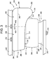
- a gas spring assembly 200 such as may be suitable for use as one of gas spring assemblies 102 in FIG. 1 , for example, has a longitudinally-extending axis AX and includes one or more end members, such as an end member (or end member assembly) 202 and an end member (or end member assembly) 204 that is spaced longitudinally from end member 202.
- a flexible spring member 206 extends peripherally around axis AX and is secured between the end members in a substantially fluid-tight manner such that a spring chamber 208 is at least partially defined therebetween.
- Gas spring assembly 200 can be disposed between associated sprung and unsprung masses of an associated vehicle in any suitable manner.
- one end member can be operatively connected to the associated sprung mass with the other end member disposed toward and operatively connected to the associated unsprung mass.
- end member 202 can be secured along a first or upper structural component USC, such as associated vehicle body BDY in FIG. 1 , for example, and can be secured thereon in any suitable manner.
- end member 204 can be secured on or along a second or lower structural component LSC, such as one of associated trailing arms 108 in FIG. 1 , for example.
- lower structural component LSC is pivotally attached to upper structural component USC such that the structural components can move relative to one another about joint JNT, as is represented by arrow PVT, for example.
- lower structural component LSC is displaced between jounce (or compressed) conditions and rebound (or extended) conditions, as is well understood by those of skill in the art.
- movement toward a jounce condition is identified by arrow JNC and movement toward a rebound condition is identified by arrow RBD.
- gas spring assembly 200 is compressed.
- the gas spring assembly in FIG. 2 is extended.
- gas spring assembly 200 and/or components thereof will typically move relative to one another through a curvilinear, rotational, arcuate, angular or other non-linear manner.
- End members 202 and 204 can be secured on or along a corresponding one of upper and lower structural components USC and LSC in any suitable manner.
- one or more securement features can be included along end member 202.
- the one or more securement features can project outwardly from the end member and can be secured on or along the structural component in a suitable manner, such as, for example, by way of one or more threaded nuts.
- one or more securement features, such as threaded passages 210, for example, can extend into end member 202.
- threaded passages 210 which can be blind passages and/or through passages, can be dimensioned to receive a corresponding securement device, such as threaded fasteners 212, for example, which can extend through one or more holes (not shown) in the structural component and into engagement with one of threaded passages 210.
- one or more securement features can be included along end member 204.
- the one or more securement features can project outwardly from the end member and can be secured on or along the structural component in a suitable manner, such as, for example, by way of one or more threaded nuts.
- one or more securement features such as threaded passage 214, for example, can extend into end member 204.
- threaded passage 214 which can be blind passages and/or through passages, can be dimensioned to receive a corresponding securement device, such as threaded fastener 216, for example, which can extend through one or more holes (not shown) in the structural component and into engagement with threaded passage 214.
- a fluid communication port such as a transfer passage 218 ( FIG. 4 ), for example, can optionally be provided to permit fluid communication with spring chamber 208, such as may be used for transferring pressurized gas into and/or out of the spring chamber, for example.
- transfer passage 218 extends into end member 202 through a wall or wall portion thereof and is in fluid communication with spring chamber 208. It will be appreciated, however, that any other suitable fluid communication arrangement could alternately be used.
- Flexible spring member 206 can be of any suitable size, shape, construction and/or configuration. Additionally, the flexible spring member can be of any type and/or kind. Flexible spring member 206 is shown in FIGS. 2-7 as being of an elongated sleeve-like design and includes a flexible wall 220 that can be formed in any suitable manner and from any suitable material or combination of materials, such as by using one or more fabric-reinforced, elastomeric plies or layers and/or one or more un-reinforced, elastomeric plies or layers, for example.
- two or more fabric-reinforced, elastomeric plies and two or more un-reinforced, elastomeric plies will be used together and formed from a common elastomeric material, such as a synthetic rubber, a natural rubber or a thermoplastic elastomer.
- a common elastomeric material such as a synthetic rubber, a natural rubber or a thermoplastic elastomer.
- a combination of two or more different materials, two or more compounds of similar materials, or two or more grades of the same material could be used.
- Flexible wall 220 extends in a generally longitudinal direction between opposing ends 222 and 224. Additionally, flexible wall 220 can include an outer surface 226 and an inner surface 228, the latter of which can at least partially define spring chamber 208. In some cases, flexible wall 220 can be constructed from a plurality of layers or plies, such as an outer or cover ply that at least partially forms outer surface 226 and an inner or liner ply that at least partially forms inner surface 228. In some cases, flexible wall 220 can further include one or more reinforcing plies disposed between the outer and inner surfaces. It will be appreciated that any such reinforcing plies, if included, can be of any suitable construction, configuration and/or arrangement.
- the one or more reinforcing plies can include one or more lengths of filament material that are at least partially embedded therein.
- the one or more lengths of filament material if provided, can be oriented in any suitable manner.
- the flexible wall can include at least one layer or ply with lengths of filament material oriented at one bias angle and at least one layer or ply with lengths of filament material oriented at an equal but opposite bias angle.
- flexible spring member 206 can be operatively connected between end members 202 and 204 in any suitable manner and that any suitable combination of features and/or components can be included on or along end member 202, end member 204 and/or flexible spring member 206.
- flexible spring member 206 can, optionally, include a mounting bead disposed along either one or both of ends 222 and 224 of flexible wall 220.
- mounting beads 230 and 232 are shown as being respectively disposed along ends 222 and 224.
- the mounting beads can, optionally, include a reinforcing element, such as an endless, annular bead wire 234, for example.
- the one or more end members can be of any suitable type, kind, construction and/or configuration. Additionally, it will be appreciated that the one or more end members can be formed from any suitable number of one or more elements and/or components. Furthermore, it will be appreciated that the one or more end members can include any suitable number of one or more walls and/or wall portions, and that the one or more end members can be operatively connected or otherwise secured to the flexible spring member in any suitable manner.
- end member 204 is shown as being of a type commonly referred to as a piston (or a roll-off piston) that has an outer surface 236 that abuttingly engages outer surface 226 of flexible spring member 206 such that a rolling lobe 238 is formed therealong.
- a piston or a roll-off piston
- rolling lobe 238 is displaced along outer surface 236 in a conventional manner.
- end member 204 extends generally between a first or upper end 240 and a second or lower end 242.
- end member 204 can be formed from any combination of one or more elements and/or components.
- End member 204 can include an end member body 244 that is formed from a base member 246 and an outer shell 248, which is operatively connected to the base member such that a substantially fluid-tight seal is formed therebetween, such as through the use of a flowed-material joint 250 extending peripherally about axis AX, for example.
- an end member body could be used in which the base member and outer shell are integrally formed with one another. In such case, the base member could be alternately referred to as a base portion or base member portion, and the outer shell could be alternately referred to as an outer shell portion.
- Outer shell (or outer shell portion) 248 can include a shell wall 252 that extends peripherally about axis AX.
- Shell wall 252 can include an outer side wall portion 254 that extends in a generally longitudinal direction between ends 240 and 242.
- Shell wall 252 also includes an end wall portion 256 that transitions into outer side wall portion 254 at a curved or shoulder portion 258.
- An inner side wall portion 260 can project from end wall portion 256 in a direction extending axially away from end 242.
- Inner side wall portion 260 can terminate in the axial direction at an end 262.
- inner side wall portion 260 can include an outer surface (not numbered) facing radially outward and an inner surface 264 facing radially inward.
- One or more projections 266 can optionally extend radially outward from along the outer surface adjacent end 262 of inner side wall portion 260. In some cases, a substantially continuous, annular projection can be used. It will be recognized that a wide variety of shapes, profiles and/or configurations can and have been used in forming the outer side wall of piston-type end members for gas spring assemblies. As such, it will be appreciated that outer side wall portion 254 of shell wall 252 can be of any suitable shape, profile and/or configuration and that the profile shown in FIGS. 2 and 4-6 is merely exemplary.
- mounting bead 232 of flexible spring member 206 can be received on or along the outer surface of inner side wall portion 260 such that a substantially fluid-tight seal is formed therebetween.
- projection 266 can assist in at least partially retaining mounting bead 232 on or along inner side wall portion 260.
- outer side wall portion 254 of shell wall 252 can include an inside surface 268 as well as outside surface 236.
- a portion of flexible spring member 206 can extend along end wall portion 256 and outside surface 236 of outer side wall portion 254 such that rolling lobe 238 is formed along end member body 244 and is displaced along the outer side wall portion as the gas spring assembly undergoes changes in overall height.
- Base member 246 includes a base member wall 270 that can include an inside surface 272 and an outside surface 274, which can be disposed in abutting engagement with lower structural component LSC.
- Inside surface 272 of base member 246 and inside surface 268 of outer side wall portion 254 can at least partially define an end member chamber 276 within end member 204, which can be in fluid communication with spring chamber 208 or an external atmosphere EXT.
- one or more openings, passages and/or conduits can extend through one or more portions of shell wall 252 such that end member chamber 276 can be disposed in fluid communication with spring chamber 208. It will be appreciated that openings, passages and/or conduits of any suitable size, shape and/or quantity can be used.
- an opening 278 extends through end wall portion 256 of shell wall 252 through which end member chamber 276 can be in fluid communication with spring chamber 208.
- opening 278 can be of sufficient size to permit end member chamber 278 and spring chamber 208 to operate as a substantially unified fluid chamber. That is, opening 278 can be sufficiently large that minimal fluid flow restriction (e.g., approximate zero fluid flow restriction) will occur for pressurized gas flowing between spring chamber 208 and end member chamber 276 under typical conditions of operation.
- opening 278 can at least partially form a passage, orifice or conduit of sufficient size and/or length to provide pressurized gas damping due to gas flow through the opening and thereby dissipate kinetic energy acting on gas spring assembly 200.
- end member 202 extends generally between a first or upper end 280 and a second or lower end 282.
- end member 202 can be formed from any combination of one or more elements and/or components.
- end member 202 can include an end member body 284 that is formed from a first or upper shell 286 and a second or lower shell 288.
- First and second shells 286 and 288 are shown in FIGS. 5 and 6 as being operatively connected to one another such that a substantially fluid-tight seal is formed therebetween. It will be appreciated that the first and second shells can be attached or otherwise operatively connected to one another in any suitable manner.
- flowed-material joints 290 and 292 can be formed between abutting edges of the first and second shells.
- joints 290 and 292 can extend peripherally about axis AX, for example, such that substantially fluid-tight seals are formed between adjacent features of first and second shells 286 and 288.
- an end member body could be formed from two or more shells having different configurations and/or arrangements.
- the walls, wall portions and joint locations of end member body 284 are merely exemplary.
- end members can include any suitable number of one or more walls and/or wall portions.
- end member body 284 of end member 202 includes a base wall portion 294 that is disposed transverse to axis AX.
- Base wall portion 294 can include an inside surface 296 and an outside surface 298, the latter of which can include an approximately planar portion dimensioned for abutting engagement with a structural component (e.g., upper structural component USC ).
- securement features such as threaded passages 210, for example, can be accessible from along base wall portion 294.
- End member body 284 of end member 202 also includes an outer wall portion 300 that extends axially from along base wall portion 294 in a first direction toward end member 204.
- Outer wall portion 300 extends peripherally about the longitudinal axis and can include an inner surface 302 and an outer surface 304, the latter of which can at least partially define an outermost periphery of end member 202.
- Outer wall portion 300 of end member body 284 includes two or more outer peripheral wall sections having different distal extents.
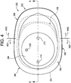
- outer wall portion 300 includes a first outer peripheral wall section 306 that extends circumferentially about axis AX in the area represented in FIG. 4 by arrows WS1.
- a second outer peripheral wall section 308 extends circumferentially about axis AX in a direction generally opposite wall section 306, as is represented in FIG. 4 by arrows WS2.
- First outer peripheral wall section 306 is shown as extending axially from along base wall portion 294 to a first distal extent disposed at a first distance from the base wall portion, as is represented in FIG. 5 by reference dimension D1.
- Second outer peripheral wall section 308 is shown as extending axially from along base wall portion 294 to a second distal extent disposed at a second distance from the base wall portion, as is represented in FIG. 5 by reference dimension D2. It will be recognized from FIGS. 3 , 5 and 6 that second distance D2 is greater than first distance D1.
- End member body 284 also includes a mounting wall portion 310 that is disposed in axially spaced relation to base wall portion 294 in a direction toward end member 204.
- Mounting wall portion 310 extends peripherally around axis AX and is spaced inward from outer wall portion 300.
- Mounting wall portion 310 is dimensioned to receivingly engage a mounting bead or other feature disposed along end 222 of flexible spring member 206.
- mounting wall portion 310 can include an annular groove (not numbered) having an open end facing radially inward and that is dimensioned to at least partially receive mounting bead 230 of flexible spring member 206 such that a substantially fluid-tight seal can be formed between end member 202 and flexible spring member 206.
- mounting wall portion 310 can include an axially-extending projection 312 having a distal edge 314 disposed toward second end member 204.
- a portion of flexible wall 220 can abuttingly engage projection 312, such as is shown in FIGS. 5 and 6 , for example.
- End member body 284 further includes an end wall portion 316 that is disposed in axially-spaced relation to base wall portion 294 and extends peripherally about axis AX.
- End wall portion 310 operatively connects outer wall portion 300 and mounting wall portion 310 to at least partially define an end member volume (not numbered) within end member 202.
- end wall portion 316 can have a non-planar peripheral profile as the end wall portion extends around axis AX.
- mounting wall portion 310 can be disposed in approximate alignment with a distal extent of an outer peripheral wall section of the outer wall portion.
- mounting wall portion 310 is disposed in spaced relation from base wall portion 294 a distance approximately equal to first distance D1 corresponding to the first distal extent of first outer peripheral wall section 306.
- second outer peripheral wall section 308 extends beyond mounting wall portion 310 and along at least a portion of flexible spring member 206.
- end member body 284 can, in some cases, include an inner support wall portion 318 extending in an approximately axial direction from along mounting wall portion 310 toward end wall portion 316.
- inner support wall portion 318 can extend peripherally about axis AX along and in inwardly-spaced relation to second outer peripheral wall section 308. In such cases, inner support wall portion 318 can extend peripherally along at least part of second outer peripheral wall section 308 in the area between arrows WS2.
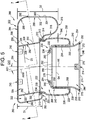
- End member body 284 further includes an inner wall portion 320 extending peripherally about axis AX and extending from along base wall portion 294 toward mounting wall portion 310.
- Inner wall portion 320 separates the end member volume (not numbered) of end member 202 into an end member reservoir 322 disposed outwardly of the inner wall portion and an end member chamber 324 disposed inwardly of the inner wall portion.
- Inner wall portion 320 includes an outer surface 326 and an inner surface 328. Outer surface 326, inside surface 296 and inner surface 302 together at least partially define end member reservoir 322.
- Inner surface 328 and inside surface 296 at least partially define end member chamber 324, which, in a preferred arrangement, is substantially contiguous with spring chamber 208.
- one or more openings, passages and/or conduits can extend through one or more portions of inner wall portion 320 such that end member reservoir 322 and end member chamber 324 can be disposed in fluid communication with one another. It will be appreciated that openings, passages and/or conduits of any suitable size, shape and/or quantity can be used. As one example, openings 330 can extend through inner wall portion 320 through which end member reservoir 322 and end member chamber 324 can be in fluid communication with one another and with spring chamber 208. In some cases, opening 330 can be of sufficient size to permit end member reservoir 322 and end member chamber 324 to operate as a substantially contiguous or otherwise unified fluid chamber.
- openings 330 can be sufficiently large that minimal fluid flow restriction (e.g., approximate zero fluid flow restriction) will occur for pressurized gas flowing between end member reservoir 322 and end member chamber 324 under typical conditions of operation.
- openings 330 can at least partially form a passage, orifice or conduit of sufficient size and/or length to provide pressurized gas damping due to gas flow through the openings and thereby dissipate kinetic energy acting on gas spring assembly 200.
- inner wall portion 320 extends peripherally about a wall portion axis AXW that is disposed at an included angle relative to longitudinal axis AX of gas spring assembly 200, as is represented in FIG. 5 by reference dimension AG1.
- angle AG1 is an acute angle within a range of approximately 3 degrees to approximately 15 degrees.
- inner wall portion 320 has an approximately circular cross-sectional profile such that the inner wall portion has an overall cylindrical shape disposed at an angle relative to base wall portion 294 and mounting wall portion 310, which are oriented transverse (e.g., at least approximately perpendicular) to longitudinal axis AX.
- inner wall portion 320 is has a cross-sectional dimension across inner surfaces, which is represented by reference dimension D3 in FIG. 5 .
- flexible wall 220 has a cross-sectional wall thickness THK ( FIG. 5 ) extending between outer and inner surfaces 226 and 228 .
- THK cross-sectional wall thickness
- a cross-sectional dimension is formed across the inner surface of the flexible wall, as is represented in FIG. 5 by reference dimension D4 .
- cross-sectional dimension D4 is roughly equal to the cross-sectional dimension across outer surface 236 of end member 204 plus two times the thickness of the flexible wall (e.g., wall thickness THK ).
- cross-sectional dimension D3 across inner surface 328 of inner wall portion 320 can be greater than cross-sectional dimension D4 such that at least a portion of end member 204 together with a portion of flexible wall 220 extending therealong can be at least partially received within end member chamber 324.
- cross-sectional dimension D3 can be within a range of from approximately 105 percent to approximately 160 percent of cross-sectional dimension D4 and, more preferably, within a range of from approximately 110 percent to approximately 140 percent of cross-sectional dimension D4.
- Gas spring assembly 200 is shown in FIGS. 2 , 3 and 5 disposed at a nominal or design height at approximately which the gas spring assembly maintain during conventional use.
- end members 202 and 204 are displaced toward one another toward a compressed or jounce condition.
- one or both of the end members will travel through a curvilinear, rotational, arcuate, angular or other non-linear motion.
- End member 204 is shown in FIG. 6 as including an end member axis AXM.
- pivot point PVT of lower structural component LSC results in movement of end member 204 through a curve or arc, which results in end member 204 and axis AXM thereof being disposed at an included angle relative to longitudinal axis AX, as is represented in FIG. 6 by reference dimension AG2.
- angle AG1 of inner wall portion 320 is approximately equal to angle AG2 experienced by end member 204 under a full jounce condition.
- any suitable angle or range of angles can be used for angles AG1 and AG2, such as may vary from application-to-application.
- circumferential is to be broadly interpreted and can include, but are not limited to circular shapes and/or configurations.
- the terms “circumferential,” “circumferentially,” and the like can be synonymous with terms such as “peripheral,” “peripherally,” and the like.
- the phrase "flowed-material joint" and the like, if used herein, are to be interpreted to include any joint or connection in which a liquid or otherwise flowable material (e.g., a melted metal or combination of melted metals) is deposited or otherwise presented between adjacent component parts and operative to form a fixed and substantially fluid-tight connection therebetween.
- a liquid or otherwise flowable material e.g., a melted metal or combination of melted metals
- processes that can be used to form such a flowed-material joint include, without limitation, welding processes, brazing processes and soldering processes.
- one or more metal materials and/or alloys can be used to form such a flowed-material joint, in addition to any material from the component parts themselves.
- Another example of a process that can be used to form a flowed-material joint includes applying, depositing or otherwise presenting an adhesive between adjacent component parts that is operative to form a fixed and substantially fluid-tight connection therebetween.
- any suitable adhesive material or combination of materials can be used, such as one-part and/or two-part epoxies, for example.
- gas is used herein to broadly refer to any gaseous or vaporous fluid. Most commonly, air is used as the working medium of gas spring devices, such as those described herein, as well as suspension systems and other components thereof. However, it will be understood that any suitable gaseous fluid could alternately be used.
Claims (15)
- Élément d'extrémité de ressort à gaz (202) ayant un axe longitudinal (AX) et étant dimensionné pour une fixation à un élément ressort flexible associé (206), ledit élément d'extrémité de ressort à gaz (202) comprenant :une paroi d'élément d'extrémité au moins partiellement formée de l'un parmi un matériau métallique et un matériau polymère, ladite paroi d'élément d'extrémité incluant :une partie de paroi de base (294) disposée transversale audit axe longitudinal (AX) ;une partie de paroi externe (300) s'étendant axialement depuis le long de ladite partie de paroi de base (294) dans une première direction, ladite partie de paroi externe (300) s'étendant de façon périphérique autour dudit axe longitudinal (AX) et définissant au moins partiellement une périphérie la plus externe dudit élément d'extrémité de ressort à gaz (202), ladite partie de paroi externe (300) incluant :une première section de paroi périphérique externe (306) avec une première étendue distale disposée à une première distance (D1) de ladite partie de paroi de base (294) ; etune deuxième section de paroi périphérique externe (308) avec une deuxième étendue distale disposée à une deuxième distance (D2) de ladite partie de paroi de base (294) avec ladite deuxième distance (D2) étant supérieure à ladite première distance (D1) ;une partie de paroi de montage (310) s'étendant de façon périphérique autour dudit axe longitudinal (AX) et espacée vers l'intérieur par rapport à ladite partie de paroi externe (300), ladite partie de paroi de montage (310) dimensionnée pour venir en prise par réception avec une extrémité associée de l'élément ressort flexible associé (306), ladite partie de paroi de montage (310) disposée dans une relation axialement espacée par rapport à ladite partie de paroi de base (294) dans ladite première direction de telle sorte que ladite deuxième section de paroi périphérique externe (308) s'étend au-delà de ladite partie de paroi de montage (310) et le long d'au moins une partie de l'élément ressort flexible associé (206) ;une partie de paroi d'extrémité (316) s'étendant de façon périphérique autour dudit axe longitudinal (AX) et reliant opérationnellement ladite partie de paroi externe (300) et ladite partie de paroi de montage (310) pour définir au moins partiellement un volume d'élément d'extrémité au sein dudit élément d'extrémité de ressort à gaz (202) ; etune partie de paroi interne (320) s'étendant de façon périphérique autour dudit axe longitudinal (AX) et s'étendant depuis le long de ladite partie de paroi de base (294) dans ladite première direction en direction de ladite partie de paroi de montage (310), ladite partie de paroi interne (320) séparant ledit volume d'élément d'extrémité en un réservoir d'élément d'extrémité (322) disposé vers l'extérieur de ladite partie de paroi interne (320) et une chambre d'élément d'extrémité (324) disposée vers l'intérieur de ladite partie de paroi interne (320).
- Élément d'extrémité de ressort à gaz (202) selon la revendication 1, dans lequel ladite partie de paroi d'extrémité (316) s'étend entre ladite partie de paroi de montage (310) et lesdites première et deuxième sections de paroi périphérique externe (306 ;308) de ladite partie de paroi externe (300) de telle sorte que ladite partie de paroi d'extrémité (316) a un profil périphérique non plan autour dudit axe longitudinal (AX).
- Élément d'extrémité de ressort à gaz (202) selon la revendication 1 ou la revendication 2, dans lequel ladite partie de paroi de montage (310) est décalée de ladite partie de paroi de base (294) d'une distance inférieure à ladite deuxième distance (D2) de ladite deuxième section de paroi périphérique externe (308) de telle sorte qu'au moins une partie de ladite partie de paroi d'extrémité (316) est disposée au-delà de ladite partie de paroi de montage (310) dans ladite première direction.
- Élément d'extrémité de ressort à gaz (202) selon l'une quelconque des revendications 1 à 3, dans lequel ladite paroi d'élément d'extrémité inclut une partie de paroi de support interne (318) disposée vers l'intérieur à partir de ladite partie de paroi externe (300), ladite partie de paroi de support interne (318) s'étendant entre ladite partie de paroi de montage (310) et ladite partie de paroi d'extrémité (316) et s'étendant de façon périphérique autour dudit axe longitudinal (AX) le long d'au moins une partie de ladite deuxième section de paroi périphérique externe (308).
- Élément d'extrémité de ressort à gaz (202) selon l'une quelconque des revendications 1 à 4, dans lequel ladite partie de paroi de montage (310) est décalée de ladite partie de paroi de base (294) d'une distance approximativement égale à ladite première distance (D1) de ladite première étendue distale.
- Élément d'extrémité de ressort à gaz (202) selon l'une quelconque des revendications 1 à 5, dans lequel ladite partie de paroi interne (320) a un axe de partie de paroi (AXW) disposé selon un premier angle aigu (AG1) par rapport audit axe longitudinal (AX).
- Élément d'extrémité de ressort à gaz (202) selon la revendication 6, dans lequel ledit premier angle aigu (AG1) est à l'intérieur d'une plage allant d'approximativement 3 degrés à approximativement 15 degrés.
- Élément d'extrémité de ressort à gaz (202) selon l'une quelconque des revendications 1 à 7, dans lequel ladite partie de paroi interne (320) s'étend entre et relie opérationnellement ladite partie de paroi de base (294) et ladite partie de paroi de montage (310).
- Ensemble ressort à gaz (102 ; 200) déplaçable entre des conditions étendue et comprimée, ledit ensemble ressort à gaz (102 ; 200) comprenant :un élément ressort flexible (206) incluant une paroi flexible (220) s'étendant longitudinalement entre une première extrémité (222) et une deuxième extrémité (224) et de façon périphérique autour dudit axe longitudinal (AX) pour définir au moins partiellement une chambre de ressort ;un premier élément d'extrémité de ressort à gaz (204) fixé par l'intermédiaire de ladite première extrémité (222) dudit élément ressort flexible (206) de telle sorte qu'un joint essentiellement étanche aux fluides est formé entre eux ; etun deuxième élément d'extrémité de ressort à gaz (202) selon l'une quelconque des revendications 1 à 8 disposé en relation espacée par rapport audit premier élément d'extrémité (204) et fixé par l'intermédiaire de ladite deuxième extrémité (224) dudit élément ressort flexible (206) de telle sorte qu'un joint essentiellement étanche aux fluides est formé entre eux.
- Ensemble ressort à gaz (102 ; 200) selon la revendication 9, dans lequel ledit premier élément d'extrémité (204) inclut une paroi latérale externe (254) avec une surface extérieure (236) le long de laquelle ladite paroi flexible (220) dudit élément ressort flexible (206) peut former un soufflet tubulaire (238) qui est déplaçable le long de ladite surface extérieure (236) dudit premier élément d'extrémité (204) à mesure que ledit ensemble ressort à gaz est déplacé entre lesdites conditions étendue et comprimée.
- Ensemble ressort à gaz (102 ; 200) selon la revendication 9 ou la revendication 10, dans lequel ladite paroi flexible (220) dudit élément ressort flexible a une surface externe (226) disposée en mise en prise en butée avec ladite surface extérieure (236) de ladite paroi latérale externe (254) dudit premier élément d'extrémité (204) et une surface interne (228) qui définit au moins partiellement ladite chambre de ressort, ladite surface interne (228) ayant une dimension en coupe transversale (D4) transversale audit axe longitudinal (AX) le long d'une partie de ladite paroi flexible (220) disposée le long dudit premier élément d'extrémité (204), ladite partie de paroi interne (320) a un axe de partie de paroi (AXW) disposé selon un premier angle aigu (AG1) par rapport audit axe longitudinal (AX), ladite partie de paroi interne (320) a une dimension en coupe transversale (D3) transversale audit axe de partie de paroi (AXW) qui est supérieure à ladite dimension en coupe transversale (D4) de ladite surface interne (228) de telle sorte qu'au moins une partie dudit premier élément d'extrémité (204) et au moins une partie dudit élément ressort flexible (206) disposé le long dudit premier élément d'extrémité (204) peuvent être reçues au sein de ladite chambre d'élément d'extrémité (324) dudit deuxième élément d'extrémité (202).
- Ensemble ressort à gaz (102 ; 200) selon l'une quelconque des revendications 10 à 12, dans lequel ladite dimension en coupe transversale (D3) de ladite partie de paroi interne (320) est à l'intérieur d'une plage allant d'approximativement 110 pour cent à approximativement 140 pour cent de ladite dimension en coupe transversale (D4) par l'intermédiaire de ladite surface interne (228) de ladite paroi flexible (220).
- Ensemble ressort à gaz (102 ; 200) selon l'une quelconque des revendications 9 à 12, dans lequel ledit premier élément d'extrémité (204) inclut un axe d'élément d'extrémité (AXM) et pendant un déplacement dudit ensemble ressort à gaz (102 ; 200) entre lesdites conditions étendue et comprimée ledit élément d'extrémité (204) est déplaçable entre une première orientation dans laquelle ledit axe d'élément d'extrémité (AXM) est au moins approximativement aligné avec ledit axe longitudinal (AX) et une deuxième orientation dans laquelle ledit deuxième axe d'élément d'extrémité (AXM) est disposé selon un deuxième angle aigu (AG2) par rapport audit axe longitudinal (AX)
- Ensemble ressort à gaz (102 ; 200) selon la revendication 13, dans lequel ladite partie de paroi interne (320) a un axe de partie de paroi (AXW) disposé selon un premier angle aigu (AG1) par rapport audit axe longitudinal (AX), et lesdits premier et deuxième angles aigus (AG1 ; AG2) sont dans une plage allant d'approximativement 3 degrés à approximativement 15 degrés.
- Système de suspension (100) comprenant :un système de gaz sous pression incluant une source de gaz sous pression (112) et un dispositif de commande (114) ; etau moins un ensemble ressort à gaz (102 ; 200) selon l'une quelconque des revendications 9 à 14 disposé en communication fluidique avec ladite source de gaz sous pression (112) par l'intermédiaire dudit dispositif de commande (114) de telle sorte que du gaz sous pression peut être transféré sélectivement vers l'intérieur et l'extérieur de ladite chambre de ressort (208).
Applications Claiming Priority (2)
| Application Number | Priority Date | Filing Date | Title |
|---|---|---|---|
| US201461990881P | 2014-05-09 | 2014-05-09 | |
| PCT/US2015/029860 WO2015172004A1 (fr) | 2014-05-09 | 2015-05-08 | Élément d'extrémité à ressort à gaz ainsi qu'ensembles de ressorts à gaz comprenant celui-ci |
Publications (2)
| Publication Number | Publication Date |
|---|---|
| EP3140137A1 EP3140137A1 (fr) | 2017-03-15 |
| EP3140137B1 true EP3140137B1 (fr) | 2021-04-14 |
Family
ID=53177402
Family Applications (1)
| Application Number | Title | Priority Date | Filing Date |
|---|---|---|---|
| EP15722421.3A Active EP3140137B1 (fr) | 2014-05-09 | 2015-05-08 | Élément d'extrémité à ressort à gaz ainsi qu'ensembles de ressorts à gaz comprenant celui-ci |
Country Status (3)
| Country | Link |
|---|---|
| US (1) | US9527358B2 (fr) |
| EP (1) | EP3140137B1 (fr) |
| WO (1) | WO2015172004A1 (fr) |
Families Citing this family (7)
| Publication number | Priority date | Publication date | Assignee | Title |
|---|---|---|---|---|
| DE102013113577B4 (de) * | 2013-12-05 | 2022-10-06 | Saf-Holland Gmbh | Abrollkolben |
| KR101575269B1 (ko) * | 2014-11-10 | 2015-12-07 | 현대자동차 주식회사 | 푸셔 액슬 시스템용 에어 스프링 장치 |
| USD784862S1 (en) * | 2015-05-08 | 2017-04-25 | Firestone Industrial Products Company, Llc | Gas spring end members |
| WO2017004472A1 (fr) * | 2015-07-01 | 2017-01-05 | Firestone Industrial Products Company, Llc | Plaque de serrage et ensembles de ressorts à pression gazeuse ainsi que des systèmes et des procédés de suspension comprenant ceux-ci |
| DE102016112307A1 (de) * | 2016-07-05 | 2018-01-11 | Progress-Werk Oberkirch Aktiengesellschaft | Verfahren zum Herstellen eines Druckbehälters sowie derartiger Druckbehälter |
| EP3563074A4 (fr) | 2016-12-31 | 2020-08-26 | Firestone Industrial Products Company, LLC | Ensembles ressort à gaz et amortisseur à gaz, ainsi que des systèmes de suspension et procédés incluant ceux-ci |
| USD878250S1 (en) * | 2019-10-10 | 2020-03-17 | Jiali Huang | Automotive hydraulic rod |
Family Cites Families (9)
| Publication number | Priority date | Publication date | Assignee | Title |
|---|---|---|---|---|
| US2917319A (en) | 1956-11-19 | 1959-12-15 | Gen Motors Corp | Plural compartment fluid suspension for vehicles |
| DE1048165B (de) * | 1957-02-20 | 1958-12-31 | Phoenix Gummiwerke Ag | Luftfeder, insbesondere fuer Kraftfahrzeuge |
| US3038716A (en) | 1960-02-24 | 1962-06-12 | Firestone Tire & Rubber Co | Automobile suspension |
| FR1304020A (fr) * | 1961-03-28 | 1962-09-21 | élément de suspension et d'amortissement pneumatique pour véhicules | |
| IT1224466B (it) * | 1988-10-04 | 1990-10-04 | Fiat Auto Spa | Dispositivo di sospensione per veicoli comprendente un ammortizzatore telescopico ed una molla ad aria |
| DE4018712A1 (de) | 1990-06-12 | 1991-12-19 | Bosch Gmbh Robert | Luftfeder mit umschaltbarer federsteifigkeit |
| WO2000075527A1 (fr) | 1999-06-09 | 2000-12-14 | Speirs Robertson And Company Limited | Antivibrateur a air, amorti et de forme ramassee |
| KR101218834B1 (ko) * | 2010-09-29 | 2013-01-07 | 주식회사 만도 | 차체 거동 감응형 에어 스프링 |
| WO2012087917A1 (fr) | 2010-12-20 | 2012-06-28 | Firestone Industrial Products Company, Llc | Piston à ressort à gaz et ensemble ressort à gaz l'utilisant |
-
2015
- 2015-05-08 US US14/707,286 patent/US9527358B2/en active Active
- 2015-05-08 EP EP15722421.3A patent/EP3140137B1/fr active Active
- 2015-05-08 WO PCT/US2015/029860 patent/WO2015172004A1/fr active Application Filing
Non-Patent Citations (1)
| Title |
|---|
| None * |
Also Published As
| Publication number | Publication date |
|---|---|
| WO2015172004A1 (fr) | 2015-11-12 |
| EP3140137A1 (fr) | 2017-03-15 |
| US9527358B2 (en) | 2016-12-27 |
| US20150321530A1 (en) | 2015-11-12 |
Similar Documents
| Publication | Publication Date | Title |
|---|---|---|
| EP3140137B1 (fr) | Élément d'extrémité à ressort à gaz ainsi qu'ensembles de ressorts à gaz comprenant celui-ci | |
| US10005333B2 (en) | End member assemblies and travel-restraint assemblies as well as gas spring assemblies including same | |
| US9259985B2 (en) | Gas spring and damper assemblies and methods | |
| EP3140564B1 (fr) | Ensembles ressort à gaz et amortisseur à gaz et systèmes de suspension les comprenant | |
| EP3224066B1 (fr) | Ensembles éléments d'extrémité et ensembles ressorts à gaz, et systèmes de suspension et procédés comprenant ces éléments | |
| US10421328B2 (en) | End member assemblies as well as gas spring assemblies, suspension systems and methods | |
| US11661991B2 (en) | Gas spring and gas damper assemblies as well as suspension systems and methods of assembly | |
| WO2013052930A2 (fr) | Ensemble ressort et amortisseur à gaz et procédé associé | |
| EP2855965A1 (fr) | Ensemble ressort pneumatique et amortisseur pneumatique | |
| US11577571B2 (en) | Gas spring end member assemblies as well as gas spring assemblies including same | |
| US11413921B2 (en) | End mount assemblies as well as gas spring and damper assemblies including same | |
| US11802604B2 (en) | Gas spring and damper assemblies as well as suspension systems including same | |
| US20200256418A1 (en) | Inertia-actuated valve assemblies as well as gas spring and gas damper assemblies, suspension systems and methods including same | |
| EP3303022B1 (fr) | Ensembles d'éléments d'extrémité et ensembles de ressorts à gaz les comprenant | |
| WO2018125662A1 (fr) | Ensembles éléments d'extrémité et ensembles ressort à gaz et amortisseur à gaz, systèmes et procédés de suspension | |
| WO2015195637A1 (fr) | Éléments d'extrémité et ensembles de ressorts à gaz les comprenant |
Legal Events
| Date | Code | Title | Description |
|---|---|---|---|
| STAA | Information on the status of an ep patent application or granted ep patent |
Free format text: STATUS: THE INTERNATIONAL PUBLICATION HAS BEEN MADE |
|
| PUAI | Public reference made under article 153(3) epc to a published international application that has entered the european phase |
Free format text: ORIGINAL CODE: 0009012 |
|
| STAA | Information on the status of an ep patent application or granted ep patent |
Free format text: STATUS: REQUEST FOR EXAMINATION WAS MADE |
|
| 17P | Request for examination filed |
Effective date: 20161201 |
|
| AK | Designated contracting states |
Kind code of ref document: A1 Designated state(s): AL AT BE BG CH CY CZ DE DK EE ES FI FR GB GR HR HU IE IS IT LI LT LU LV MC MK MT NL NO PL PT RO RS SE SI SK SM TR |
|
| AX | Request for extension of the european patent |
Extension state: BA ME |
|
| DAV | Request for validation of the european patent (deleted) | ||
| DAX | Request for extension of the european patent (deleted) | ||
| RAP1 | Party data changed (applicant data changed or rights of an application transferred) |
Owner name: FIRESTONE INDUSTRIAL PRODUCTS COMPANY, LLC |
|
| STAA | Information on the status of an ep patent application or granted ep patent |
Free format text: STATUS: EXAMINATION IS IN PROGRESS |
|
| 17Q | First examination report despatched |
Effective date: 20190516 |
|
| GRAP | Despatch of communication of intention to grant a patent |
Free format text: ORIGINAL CODE: EPIDOSNIGR1 |
|
| STAA | Information on the status of an ep patent application or granted ep patent |
Free format text: STATUS: GRANT OF PATENT IS INTENDED |
|
| INTG | Intention to grant announced |
Effective date: 20201106 |
|
| GRAS | Grant fee paid |
Free format text: ORIGINAL CODE: EPIDOSNIGR3 |
|
| GRAA | (expected) grant |
Free format text: ORIGINAL CODE: 0009210 |
|
| STAA | Information on the status of an ep patent application or granted ep patent |
Free format text: STATUS: THE PATENT HAS BEEN GRANTED |
|
| AK | Designated contracting states |
Kind code of ref document: B1 Designated state(s): AL AT BE BG CH CY CZ DE DK EE ES FI FR GB GR HR HU IE IS IT LI LT LU LV MC MK MT NL NO PL PT RO RS SE SI SK SM TR |
|
| REG | Reference to a national code |
Ref country code: GB Ref legal event code: FG4D |
|
| REG | Reference to a national code |
Ref country code: CH Ref legal event code: EP |
|
| REG | Reference to a national code |
Ref country code: DE Ref legal event code: R096 Ref document number: 602015068068 Country of ref document: DE |
|
| REG | Reference to a national code |
Ref country code: IE Ref legal event code: FG4D |
|
| REG | Reference to a national code |
Ref country code: AT Ref legal event code: REF Ref document number: 1382031 Country of ref document: AT Kind code of ref document: T Effective date: 20210515 |
|
| REG | Reference to a national code |
Ref country code: LT Ref legal event code: MG9D |
|
| REG | Reference to a national code |
Ref country code: AT Ref legal event code: MK05 Ref document number: 1382031 Country of ref document: AT Kind code of ref document: T Effective date: 20210414 |
|
| REG | Reference to a national code |
Ref country code: NL Ref legal event code: MP Effective date: 20210414 |
|
| PG25 | Lapsed in a contracting state [announced via postgrant information from national office to epo] |
Ref country code: HR Free format text: LAPSE BECAUSE OF FAILURE TO SUBMIT A TRANSLATION OF THE DESCRIPTION OR TO PAY THE FEE WITHIN THE PRESCRIBED TIME-LIMIT Effective date: 20210414 Ref country code: BG Free format text: LAPSE BECAUSE OF FAILURE TO SUBMIT A TRANSLATION OF THE DESCRIPTION OR TO PAY THE FEE WITHIN THE PRESCRIBED TIME-LIMIT Effective date: 20210714 Ref country code: AT Free format text: LAPSE BECAUSE OF FAILURE TO SUBMIT A TRANSLATION OF THE DESCRIPTION OR TO PAY THE FEE WITHIN THE PRESCRIBED TIME-LIMIT Effective date: 20210414 Ref country code: LT Free format text: LAPSE BECAUSE OF FAILURE TO SUBMIT A TRANSLATION OF THE DESCRIPTION OR TO PAY THE FEE WITHIN THE PRESCRIBED TIME-LIMIT Effective date: 20210414 Ref country code: NL Free format text: LAPSE BECAUSE OF FAILURE TO SUBMIT A TRANSLATION OF THE DESCRIPTION OR TO PAY THE FEE WITHIN THE PRESCRIBED TIME-LIMIT Effective date: 20210414 Ref country code: FI Free format text: LAPSE BECAUSE OF FAILURE TO SUBMIT A TRANSLATION OF THE DESCRIPTION OR TO PAY THE FEE WITHIN THE PRESCRIBED TIME-LIMIT Effective date: 20210414 |
|
| PG25 | Lapsed in a contracting state [announced via postgrant information from national office to epo] |
Ref country code: LV Free format text: LAPSE BECAUSE OF FAILURE TO SUBMIT A TRANSLATION OF THE DESCRIPTION OR TO PAY THE FEE WITHIN THE PRESCRIBED TIME-LIMIT Effective date: 20210414 Ref country code: IS Free format text: LAPSE BECAUSE OF FAILURE TO SUBMIT A TRANSLATION OF THE DESCRIPTION OR TO PAY THE FEE WITHIN THE PRESCRIBED TIME-LIMIT Effective date: 20210814 Ref country code: GR Free format text: LAPSE BECAUSE OF FAILURE TO SUBMIT A TRANSLATION OF THE DESCRIPTION OR TO PAY THE FEE WITHIN THE PRESCRIBED TIME-LIMIT Effective date: 20210715 Ref country code: NO Free format text: LAPSE BECAUSE OF FAILURE TO SUBMIT A TRANSLATION OF THE DESCRIPTION OR TO PAY THE FEE WITHIN THE PRESCRIBED TIME-LIMIT Effective date: 20210714 Ref country code: PL Free format text: LAPSE BECAUSE OF FAILURE TO SUBMIT A TRANSLATION OF THE DESCRIPTION OR TO PAY THE FEE WITHIN THE PRESCRIBED TIME-LIMIT Effective date: 20210414 Ref country code: PT Free format text: LAPSE BECAUSE OF FAILURE TO SUBMIT A TRANSLATION OF THE DESCRIPTION OR TO PAY THE FEE WITHIN THE PRESCRIBED TIME-LIMIT Effective date: 20210816 Ref country code: ES Free format text: LAPSE BECAUSE OF FAILURE TO SUBMIT A TRANSLATION OF THE DESCRIPTION OR TO PAY THE FEE WITHIN THE PRESCRIBED TIME-LIMIT Effective date: 20210414 Ref country code: SE Free format text: LAPSE BECAUSE OF FAILURE TO SUBMIT A TRANSLATION OF THE DESCRIPTION OR TO PAY THE FEE WITHIN THE PRESCRIBED TIME-LIMIT Effective date: 20210414 Ref country code: RS Free format text: LAPSE BECAUSE OF FAILURE TO SUBMIT A TRANSLATION OF THE DESCRIPTION OR TO PAY THE FEE WITHIN THE PRESCRIBED TIME-LIMIT Effective date: 20210414 |
|
| REG | Reference to a national code |
Ref country code: CH Ref legal event code: PL |
|
| REG | Reference to a national code |
Ref country code: DE Ref legal event code: R097 Ref document number: 602015068068 Country of ref document: DE |
|
| PG25 | Lapsed in a contracting state [announced via postgrant information from national office to epo] |
Ref country code: SM Free format text: LAPSE BECAUSE OF FAILURE TO SUBMIT A TRANSLATION OF THE DESCRIPTION OR TO PAY THE FEE WITHIN THE PRESCRIBED TIME-LIMIT Effective date: 20210414 Ref country code: SK Free format text: LAPSE BECAUSE OF FAILURE TO SUBMIT A TRANSLATION OF THE DESCRIPTION OR TO PAY THE FEE WITHIN THE PRESCRIBED TIME-LIMIT Effective date: 20210414 Ref country code: CZ Free format text: LAPSE BECAUSE OF FAILURE TO SUBMIT A TRANSLATION OF THE DESCRIPTION OR TO PAY THE FEE WITHIN THE PRESCRIBED TIME-LIMIT Effective date: 20210414 Ref country code: EE Free format text: LAPSE BECAUSE OF FAILURE TO SUBMIT A TRANSLATION OF THE DESCRIPTION OR TO PAY THE FEE WITHIN THE PRESCRIBED TIME-LIMIT Effective date: 20210414 Ref country code: DK Free format text: LAPSE BECAUSE OF FAILURE TO SUBMIT A TRANSLATION OF THE DESCRIPTION OR TO PAY THE FEE WITHIN THE PRESCRIBED TIME-LIMIT Effective date: 20210414 Ref country code: LI Free format text: LAPSE BECAUSE OF NON-PAYMENT OF DUE FEES Effective date: 20210531 Ref country code: MC Free format text: LAPSE BECAUSE OF FAILURE TO SUBMIT A TRANSLATION OF THE DESCRIPTION OR TO PAY THE FEE WITHIN THE PRESCRIBED TIME-LIMIT Effective date: 20210414 Ref country code: LU Free format text: LAPSE BECAUSE OF NON-PAYMENT OF DUE FEES Effective date: 20210508 Ref country code: CH Free format text: LAPSE BECAUSE OF NON-PAYMENT OF DUE FEES Effective date: 20210531 Ref country code: RO Free format text: LAPSE BECAUSE OF FAILURE TO SUBMIT A TRANSLATION OF THE DESCRIPTION OR TO PAY THE FEE WITHIN THE PRESCRIBED TIME-LIMIT Effective date: 20210414 |
|
| REG | Reference to a national code |
Ref country code: BE Ref legal event code: MM Effective date: 20210531 |
|
| PLBE | No opposition filed within time limit |
Free format text: ORIGINAL CODE: 0009261 |
|
| STAA | Information on the status of an ep patent application or granted ep patent |
Free format text: STATUS: NO OPPOSITION FILED WITHIN TIME LIMIT |
|
| 26N | No opposition filed |
Effective date: 20220117 |
|
| GBPC | Gb: european patent ceased through non-payment of renewal fee |
Effective date: 20210714 |
|
| PG25 | Lapsed in a contracting state [announced via postgrant information from national office to epo] |
Ref country code: IE Free format text: LAPSE BECAUSE OF NON-PAYMENT OF DUE FEES Effective date: 20210508 Ref country code: GB Free format text: LAPSE BECAUSE OF NON-PAYMENT OF DUE FEES Effective date: 20210714 |
|
| PG25 | Lapsed in a contracting state [announced via postgrant information from national office to epo] |
Ref country code: IS Free format text: LAPSE BECAUSE OF FAILURE TO SUBMIT A TRANSLATION OF THE DESCRIPTION OR TO PAY THE FEE WITHIN THE PRESCRIBED TIME-LIMIT Effective date: 20210814 Ref country code: FR Free format text: LAPSE BECAUSE OF NON-PAYMENT OF DUE FEES Effective date: 20210614 Ref country code: AL Free format text: LAPSE BECAUSE OF FAILURE TO SUBMIT A TRANSLATION OF THE DESCRIPTION OR TO PAY THE FEE WITHIN THE PRESCRIBED TIME-LIMIT Effective date: 20210414 |
|
| PG25 | Lapsed in a contracting state [announced via postgrant information from national office to epo] |
Ref country code: IT Free format text: LAPSE BECAUSE OF FAILURE TO SUBMIT A TRANSLATION OF THE DESCRIPTION OR TO PAY THE FEE WITHIN THE PRESCRIBED TIME-LIMIT Effective date: 20210414 Ref country code: BE Free format text: LAPSE BECAUSE OF NON-PAYMENT OF DUE FEES Effective date: 20210531 |
|
| PG25 | Lapsed in a contracting state [announced via postgrant information from national office to epo] |
Ref country code: HU Free format text: LAPSE BECAUSE OF FAILURE TO SUBMIT A TRANSLATION OF THE DESCRIPTION OR TO PAY THE FEE WITHIN THE PRESCRIBED TIME-LIMIT; INVALID AB INITIO Effective date: 20150508 |
|
| P01 | Opt-out of the competence of the unified patent court (upc) registered |
Effective date: 20230524 |
|
| PG25 | Lapsed in a contracting state [announced via postgrant information from national office to epo] |
Ref country code: CY Free format text: LAPSE BECAUSE OF FAILURE TO SUBMIT A TRANSLATION OF THE DESCRIPTION OR TO PAY THE FEE WITHIN THE PRESCRIBED TIME-LIMIT Effective date: 20210414 |
|
| PGFP | Annual fee paid to national office [announced via postgrant information from national office to epo] |
Ref country code: DE Payment date: 20230419 Year of fee payment: 9 |
|
| PG25 | Lapsed in a contracting state [announced via postgrant information from national office to epo] |
Ref country code: MK Free format text: LAPSE BECAUSE OF FAILURE TO SUBMIT A TRANSLATION OF THE DESCRIPTION OR TO PAY THE FEE WITHIN THE PRESCRIBED TIME-LIMIT Effective date: 20210414 |