EP3139838B1 - Imaging systems and methods for positioning a 3d ultrasound volume in a desired orientation - Google Patents
Imaging systems and methods for positioning a 3d ultrasound volume in a desired orientation Download PDFInfo
- Publication number
- EP3139838B1 EP3139838B1 EP15726728.7A EP15726728A EP3139838B1 EP 3139838 B1 EP3139838 B1 EP 3139838B1 EP 15726728 A EP15726728 A EP 15726728A EP 3139838 B1 EP3139838 B1 EP 3139838B1
- Authority
- EP
- European Patent Office
- Prior art keywords
- anatomical feature
- orientation
- ultrasound
- lighting
- image data
- Prior art date
- Legal status (The legal status is an assumption and is not a legal conclusion. Google has not performed a legal analysis and makes no representation as to the accuracy of the status listed.)
- Active
Links
- 238000002604 ultrasonography Methods 0.000 title claims description 72
- 238000000034 method Methods 0.000 title claims description 25
- 238000003384 imaging method Methods 0.000 title description 8
- 238000009877 rendering Methods 0.000 claims description 30
- 210000003754 fetus Anatomy 0.000 claims description 22
- 239000000523 sample Substances 0.000 claims description 20
- 230000001815 facial effect Effects 0.000 claims description 2
- 210000002216 heart Anatomy 0.000 description 7
- 230000001605 fetal effect Effects 0.000 description 5
- 210000001519 tissue Anatomy 0.000 description 5
- 230000005540 biological transmission Effects 0.000 description 3
- 238000001514 detection method Methods 0.000 description 3
- 210000003625 skull Anatomy 0.000 description 3
- 238000012285 ultrasound imaging Methods 0.000 description 3
- 238000010586 diagram Methods 0.000 description 2
- 230000006872 improvement Effects 0.000 description 2
- 210000001331 nose Anatomy 0.000 description 2
- 230000008569 process Effects 0.000 description 2
- 238000000926 separation method Methods 0.000 description 2
- 238000002679 ablation Methods 0.000 description 1
- 210000003484 anatomy Anatomy 0.000 description 1
- 238000003491 array Methods 0.000 description 1
- 210000000988 bone and bone Anatomy 0.000 description 1
- 238000013329 compounding Methods 0.000 description 1
- 230000001419 dependent effect Effects 0.000 description 1
- 238000002059 diagnostic imaging Methods 0.000 description 1
- 230000008030 elimination Effects 0.000 description 1
- 238000003379 elimination reaction Methods 0.000 description 1
- 238000001914 filtration Methods 0.000 description 1
- 210000001061 forehead Anatomy 0.000 description 1
- 230000006870 function Effects 0.000 description 1
- 210000001983 hard palate Anatomy 0.000 description 1
- 210000003128 head Anatomy 0.000 description 1
- 210000003016 hypothalamus Anatomy 0.000 description 1
- 230000003993 interaction Effects 0.000 description 1
- 210000003734 kidney Anatomy 0.000 description 1
- 210000004185 liver Anatomy 0.000 description 1
- 238000012986 modification Methods 0.000 description 1
- 230000004048 modification Effects 0.000 description 1
- 210000000537 nasal bone Anatomy 0.000 description 1
- 210000000056 organ Anatomy 0.000 description 1
- 230000009467 reduction Effects 0.000 description 1
- 238000012216 screening Methods 0.000 description 1
- 210000000216 zygoma Anatomy 0.000 description 1
Images


Classifications
-
- A—HUMAN NECESSITIES
- A61—MEDICAL OR VETERINARY SCIENCE; HYGIENE
- A61B—DIAGNOSIS; SURGERY; IDENTIFICATION
- A61B8/00—Diagnosis using ultrasonic, sonic or infrasonic waves
- A61B8/08—Detecting organic movements or changes, e.g. tumours, cysts, swellings
- A61B8/0866—Detecting organic movements or changes, e.g. tumours, cysts, swellings involving foetal diagnosis; pre-natal or peri-natal diagnosis of the baby
-
- A—HUMAN NECESSITIES
- A61—MEDICAL OR VETERINARY SCIENCE; HYGIENE
- A61B—DIAGNOSIS; SURGERY; IDENTIFICATION
- A61B8/00—Diagnosis using ultrasonic, sonic or infrasonic waves
- A61B8/42—Details of probe positioning or probe attachment to the patient
- A61B8/4245—Details of probe positioning or probe attachment to the patient involving determining the position of the probe, e.g. with respect to an external reference frame or to the patient
-
- A—HUMAN NECESSITIES
- A61—MEDICAL OR VETERINARY SCIENCE; HYGIENE
- A61B—DIAGNOSIS; SURGERY; IDENTIFICATION
- A61B8/00—Diagnosis using ultrasonic, sonic or infrasonic waves
- A61B8/46—Ultrasonic, sonic or infrasonic diagnostic devices with special arrangements for interfacing with the operator or the patient
- A61B8/461—Displaying means of special interest
- A61B8/466—Displaying means of special interest adapted to display 3D data
-
- A—HUMAN NECESSITIES
- A61—MEDICAL OR VETERINARY SCIENCE; HYGIENE
- A61B—DIAGNOSIS; SURGERY; IDENTIFICATION
- A61B8/00—Diagnosis using ultrasonic, sonic or infrasonic waves
- A61B8/48—Diagnostic techniques
- A61B8/483—Diagnostic techniques involving the acquisition of a 3D volume of data
-
- A—HUMAN NECESSITIES
- A61—MEDICAL OR VETERINARY SCIENCE; HYGIENE
- A61B—DIAGNOSIS; SURGERY; IDENTIFICATION
- A61B8/00—Diagnosis using ultrasonic, sonic or infrasonic waves
- A61B8/52—Devices using data or image processing specially adapted for diagnosis using ultrasonic, sonic or infrasonic waves
- A61B8/5215—Devices using data or image processing specially adapted for diagnosis using ultrasonic, sonic or infrasonic waves involving processing of medical diagnostic data
-
- G—PHYSICS
- G06—COMPUTING; CALCULATING OR COUNTING
- G06T—IMAGE DATA PROCESSING OR GENERATION, IN GENERAL
- G06T19/00—Manipulating 3D models or images for computer graphics
- G06T19/20—Editing of 3D images, e.g. changing shapes or colours, aligning objects or positioning parts
-
- G—PHYSICS
- G16—INFORMATION AND COMMUNICATION TECHNOLOGY [ICT] SPECIALLY ADAPTED FOR SPECIFIC APPLICATION FIELDS
- G16H—HEALTHCARE INFORMATICS, i.e. INFORMATION AND COMMUNICATION TECHNOLOGY [ICT] SPECIALLY ADAPTED FOR THE HANDLING OR PROCESSING OF MEDICAL OR HEALTHCARE DATA
- G16H50/00—ICT specially adapted for medical diagnosis, medical simulation or medical data mining; ICT specially adapted for detecting, monitoring or modelling epidemics or pandemics
- G16H50/20—ICT specially adapted for medical diagnosis, medical simulation or medical data mining; ICT specially adapted for detecting, monitoring or modelling epidemics or pandemics for computer-aided diagnosis, e.g. based on medical expert systems
-
- G—PHYSICS
- G06—COMPUTING; CALCULATING OR COUNTING
- G06T—IMAGE DATA PROCESSING OR GENERATION, IN GENERAL
- G06T2219/00—Indexing scheme for manipulating 3D models or images for computer graphics
- G06T2219/20—Indexing scheme for editing of 3D models
- G06T2219/2004—Aligning objects, relative positioning of parts
Definitions
- This invention relates to medical diagnostic ultrasound systems and, in particular, to imaging systems and methods for displaying a 3D ultrasound image in a desired view orientation.
- Document US 2011/125016 A1 relates to fetal rendering in medical diagnostic ultrasound, in which a fetal skeleton in three dimensions is determined from acquired ultrasound data and displayed as a volumetric rendering, which may be visualized from different orientations and allows the addition of lighting queues to better indicate actual size and orientation of bones relative to each other on the rendered image.
- the present invention can include acquiring 3D ultrasound image data comprising an anatomical feature in a patient.
- an actual orientation of the anatomical feature can be determined in relation to a transducer probe or other point of interest. For instance, a fetus can be imaged using a 3D ultrasound system and the orientation of the fetus's face can be determined.
- the present invention further includes displaying the 3D ultrasound image data as a rendering of the anatomical feature such that the anatomical feature is positioned in a selected orientation that is different than the actual orientation.
- the anatomical features being rendered can be positioned in spatial relation to a lighting model such that lighting and shadowing regions on the anatomical features are displayed to a user, and in some embodiments, according to a stored setting on an ultrasound system.
- an ultrasound imaging system 10 constructed in accordance with the principles of the present disclosure is shown in block diagram form.
- an ultrasound probe 12 includes a transducer array 14 for transmitting ultrasonic waves and receiving echo information.
- the transducer array 14, for example, can include a two dimensional array (as shown) of transducer elements capable of scanning in both elevation and azimuth dimensions for 2D and/or 3D imaging.
- the transducer array 14 is coupled to a microbeamformer 16 in the probe 12 which controls transmission and reception of signals by the transducer elements in the array.
- the microbeamformer is coupled by the probe cable to a transmit/receive (T/R) switch 18, which switches between transmission and reception and protects the main beamformer 22 from high energy transmit signals.
- T/R switch 18 and other elements in the system can be included in the transducer probe rather than in a separate ultrasound system base.
- the probe 12 can contain all of the components necessary for outputting a video signal that can be simply displayed by an external display.
- a system may not include a main beamformer 22, and instead beamforming may be completed in the probe 12, and the probe can also include the signal processor 26, the B mode processor 28, and other electronics for processing ultrasound signals.
- the transmission of ultrasonic beams from the transducer array 14 under control of the microbeamformer 16 is directed by the transmit controller 20 coupled to the T/R switch 18 and the beamformer 22, which receives input from the user's operation of the user interface or control panel 24.
- One of the functions controlled by the transmit controller 20 is the direction in which beams are steered. Beams may be steered straight ahead from (orthogonal to) the transducer array, or at different angles for a wider field of view.
- the partially beamformed signals produced by the microbeamformer 16 are coupled to a main beamformer 22 where partially beamformed signals from individual patches of transducer elements are combined into a fully beamformed signal.
- Patterns Groups of adjacent transducer elements referred to as “patches” or “subarrays” are integrally operated by a microbeamformer ( ⁇ BF) in the probe 12.
- ⁇ BF microbeamformer
- Suitable two dimensional arrays are described in, e.g., U.S. Patent 6,419,633 (Robinson et al. ) and in U.S. Patent 6,368,281 (Solomon et al. )
- Microbeamformers are described, e.g., in U.S. Patents 5,997,479 (Savord et al. ) and 6,013,032 (Savord ).
- the beamformed signals are coupled to a signal processor 26.
- the signal processor 26 can process the received echo signals in various ways, such as bandpass filtering, decimation, I and Q component separation, and harmonic signal separation.
- the signal processor 26 may also perform additional signal enhancement such as speckle reduction, signal compounding, and noise elimination.
- the processed signals are coupled to a B mode processor 28, which can employ amplitude detection for the imaging of anatomical features, such as a baby's face in the mother.
- the signals produced by the B mode processor are coupled to a 3D image data processor 30, which is configured to generate 3D image datasets that can be rendered and processed by the volume rendering and light model processor 32.
- the volume rendering and light model processor 32 can render an imaged anatomical feature such that the anatomical feature is positioned in a selected orientation that is different than an actual orientation of the feature in relation to the transducer probe 12.
- the volume rendering and light model processor 32 also can position the orientation of the anatomical feature in spatial relation to a lighting model such that lighting and shadowing regions on the anatomical feature are displayed according to a stored setting on an ultrasound system.
- the user interface or control panel 24 can be operated by a user to predefine the stored setting on the system and thereby generate the user's desired view of the anatomical feature along with an optimal lighting arrangement for generating renderings of the anatomical feature, such as a baby's face.
- the ultrasound systems can operate to perform any of the following steps: acquire 3D ultrasound image data comprising an anatomical feature in a patient; determine an actual orientation of the anatomical feature in space; and/or display the 3D ultrasound image data as a rendering comprising the anatomical feature such that the anatomical feature is positioned (1) in a selected orientation that is different than the actual orientation and (2) in spatial relation to a lighting model such that lighting and shadowing regions on the anatomical feature are displayed according to a stored setting on an ultrasound system.
- FIGURE 2 is a flow chart showing the workflow 40 of an implementation of the present disclosure.
- This workflow 40 begins with a step 42 that includes acquiring 3D ultrasound image data that includes at least a portion of an anatomical feature of interest.
- a 3D ultrasound imaging system can be used to collect images of a fetus in a mother.
- the anatomical features of interest might include, but are not limited to, the nose, chin, eyes and/or skull of the fetus.
- an anatomical feature of interest might include at least a portion of a patient's organ, such as a heart, kidney or liver.
- an ultrasound system can be used to process the 3D ultrasound data such that an actual orientation of the anatomical feature (e.g., a baby's face) can be determined and, optionally, displayed to a user on a screen.
- This step includes known techniques for performing 3D ultrasound imaging in which the probe transmits and receives echo data from the patient to show a 2D or 3D image of the patient's anatomy on a display.
- automated detection of the orientation of the anatomical feature can be accomplished using structural modeling and anatomical landmark identification.
- the present invention can include identifying the actual orientation by applying structural models to define a surface orientation of the anatomical feature and/or identifying anatomical landmarks in the anatomical feature.
- the method for determining the actual orientation of the anatomical feature follows the methods described in Cuignet et al., 2013 IEEE Symposium on Biomedical Imaging, pages 768-771 .
- the method of determining actual orientation can include, for example, identifying anatomical features of a fetus that are echogenic independently of the probe position: the skull, the midsagittal plane and the orbits of the eyes.
- the skull can be detected and segmented using a shape model and a template deformation algorithm. An initial anatomical frame of reference can thus be defined. Then, the detection of both the midsagittal plane and orbits of the eyes allows to remove orientation ambiguities and eventually to refine this frame of reference.
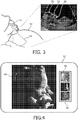
- an ultrasound image plane 50 corresponding to the sagittal plane can be acquired by traditional scanning of the mother 52 with an ultrasound probe 54.
- the forehead 56, the nose 58 and the chin 60 of the fetus can be identified using, e.g., learning-based algorithms or other models.
- other structures such as the hypothalamus, the nasal bone end, the palatine bones, and/or the cheekbone can be identified and used to determine the fetal orientation.
- embodiments of the present invention further include automated sculpting away of ultrasound data representing tissue that is not part of the facial tissue. This can be accomplished by different techniques, such as by application of the same structural model that can be applied to orient the fetal head.
- Step 46 of the workflow 40 includes displaying the 3D ultrasound data including the anatomical feature at a selected orientation that is different than the actual orientation.
- a sonographer may image a fetus such that the fetus's face is actually oriented directly looking at the transducer probe.
- a lighting model can be used to add shadowing and/or lighting aspects to the 3D rendered ultrasound data displayed to the sonographer.
- the lighting model can include one or more lights that are positioned in 3D space with respect to the rendered 3D volume of the anatomical feature, e.g., the fetus.
- the lights in the lighting model can be manually positioned by the user or they can be included in a standard set of positions that provide the optimal lighting and shadowing for a particular orientation of the 3D rendered ultrasound volume.
- relative intensities of the lighting and shadowing can be tuned by the user after displaying the 3D ultrasound image data.
- the selected orientation of the anatomical features as well as the lighting models can be saved on the system for later use and reference.
- the present invention includes displaying 3D ultrasound image data as a rendering that includes an anatomical feature of interest.
- the anatomical feature is positioned in a selected orientation that is different than the actual orientation, e.g. by the volume rendering and lighting model processor in FIG. 1 .
- the anatomical feature can also be positioned in spatial relation to a lighting model such that lighting and shadowing regions on the anatomical feature are displayed according to a stored setting on an ultrasound system.
- the stored setting for the positioning and lighting model details can be generated by a user selecting the selected orientation from a plurality of displayed orientation views.
- the stored setting can be configured to be used for a plurality of sequential ultrasound scans.
- the same selected orientation can be used for sequential patient scans such that each baby face ultrasound image has the same orientation and same lighting model for different patients.
- This aspect can improve throughput, for example, with scanning procedures such that a sonographer does not have to spend time orienting the rendering and lighting.
- the system of the present invention has a stored setting, which can be selected by a user, that initiates these steps automatically.
- FIG. 4 illustrates an embodiment of the present invention in which an ultrasound system includes three stored settings that show selecte6d orientations of the baby's face rendered in 3D and having different lighting models to highlight certain features of the baby's face.
- the display 62 for example, includes three thumbnail images 64 that show real-time renderings of the 3D ultrasound image data acquired of a baby's face.
- Each of the selected orientations 66 of the baby's face can be displayed to a user and the user can select the desired orientation among the three.
- the selected orientation of interest can be displayed in a fuller view 68 to the user.
- the image of the baby's face can be simply saved and printed or provided electronically to a mother.
- the stored settings on the system may be provided by default on an ultrasound system.
- a sonographer or other clinician can manually define the selected orientations and store those settings on the system for later use, e.g., as shown in FIG. 4 .
- the present invention can also be applied for viewing other tissue structures in a fetus, such as a hand or foot.
- a heart could be imaged similar to the fetus as described herein.
- a heart model could be used to identify the orientation of the heart, and a selected orientation could be used to show the heart at a different orientation than the actual orientation shown in the acquired 3D ultrasound data.
- the selected orientations could be designed such that a specific chamber of the heart is always displayed in a certain orientation, and in addition with lighting and shadowing to better view specific tissue areas of the heart for better diagnostic capabilities.
Description
- This invention relates to medical diagnostic ultrasound systems and, in particular, to imaging systems and methods for displaying a 3D ultrasound image in a desired view orientation.
- With the advent of
high resolution 3D renderings of ultrasound data, diagnostic ultrasound applications have seen continued improvement with better 3D imaging and increased capabilities to identify tissue features not as easily recognized in traditional 2D scanning procedures. Nevertheless, the simplicity and efficiency for certain 3D ultrasound applications still need improvement. For example, an increasingly important expectation is being placed on routine obstetrical ultrasound examinations by mothers that want 3D rendering of their baby's face. Attempting to generate this image is necessary from a business standpoint for many clinicians whose patients will go elsewhere if the service is not available. Unfortunately, obtaininggood quality 3D renderings of a baby's face can be a frustrating and time consuming exercise that also takes away from time that can be spent on ultrasound diagnostic scans having more clinical value. - Document
US 2011/125016 A1 relates to fetal rendering in medical diagnostic ultrasound, in which a fetal skeleton in three dimensions is determined from acquired ultrasound data and displayed as a volumetric rendering, which may be visualized from different orientations and allows the addition of lighting queues to better indicate actual size and orientation of bones relative to each other on the rendered image. - Thus, there is need to arrive at the desired imaging result as quickly as possible and save time for clinically relevant screening of the fetus for various potential anomalies. More generally, there is a need for better methods to display a 3D ultrasound image in a desired view orientation according to settings that are optimal for viewing for a certain ultrasound application. The present invention provides this and more.
- In accordance with the principles of the present invention, methods and systems are provided for displaying a 3D ultrasound image in a desired view orientation. The invention is defined by the independent claims. Advantageous embodiments are provided in the dependent claims. As described further herein, the present invention can include acquiring 3D ultrasound image data comprising an anatomical feature in a patient. In addition, an actual orientation of the anatomical feature can be determined in relation to a transducer probe or other point of interest. For instance, a fetus can be imaged using a 3D ultrasound system and the orientation of the fetus's face can be determined. The present invention further includes displaying the 3D ultrasound image data as a rendering of the anatomical feature such that the anatomical feature is positioned in a selected orientation that is different than the actual orientation. In addition, the anatomical features being rendered can be positioned in spatial relation to a lighting model such that lighting and shadowing regions on the anatomical features are displayed to a user, and in some embodiments, according to a stored setting on an ultrasound system.
- In the drawings:
-
FIGURE 1 illustrates in block diagram form the use of three dimensional ultrasonic imaging to guide or monitor ablation in an embodiment of the present disclosure. -
FIGURE 2 illustrates a workflow in accordance with the present disclosure for displaying 3D ultrasound data a selected orientation. -
FIGURE 3 depicts an example ultrasound procedure for identifying anatomical features in a fetus to determine the actual orientation of the fetus in a mother's womb. -
FIGURE 4 illustrates a display of different selected orientations of anatomical features that can be stored on an ultrasound system for quick and reproducible viewing by a user. - Referring to
FIG. 1 , anultrasound imaging system 10 constructed in accordance with the principles of the present disclosure is shown in block diagram form. In the ultrasonic diagnostic imaging system ofFIG. 1 , anultrasound probe 12 includes atransducer array 14 for transmitting ultrasonic waves and receiving echo information. Thetransducer array 14, for example, can include a two dimensional array (as shown) of transducer elements capable of scanning in both elevation and azimuth dimensions for 2D and/or 3D imaging. Thetransducer array 14 is coupled to amicrobeamformer 16 in theprobe 12 which controls transmission and reception of signals by the transducer elements in the array. In this example, the microbeamformer is coupled by the probe cable to a transmit/receive (T/R)switch 18, which switches between transmission and reception and protects themain beamformer 22 from high energy transmit signals. In some embodiments, the T/R switch 18 and other elements in the system can be included in the transducer probe rather than in a separate ultrasound system base. In some embodiments, theprobe 12 can contain all of the components necessary for outputting a video signal that can be simply displayed by an external display. For example, a system may not include amain beamformer 22, and instead beamforming may be completed in theprobe 12, and the probe can also include thesignal processor 26, theB mode processor 28, and other electronics for processing ultrasound signals. - As shown, the transmission of ultrasonic beams from the
transducer array 14 under control of themicrobeamformer 16 is directed by thetransmit controller 20 coupled to the T/R switch 18 and thebeamformer 22, which receives input from the user's operation of the user interface orcontrol panel 24. One of the functions controlled by thetransmit controller 20 is the direction in which beams are steered. Beams may be steered straight ahead from (orthogonal to) the transducer array, or at different angles for a wider field of view. In this embodiment, the partially beamformed signals produced by themicrobeamformer 16 are coupled to amain beamformer 22 where partially beamformed signals from individual patches of transducer elements are combined into a fully beamformed signal. Groups of adjacent transducer elements referred to as "patches" or "subarrays" are integrally operated by a microbeamformer (µBF) in theprobe 12. Suitable two dimensional arrays are described in, e.g.,U.S. Patent 6,419,633 (Robinson et al. ) and inU.S. Patent 6,368,281 (Solomon et al. ) Microbeamformers are described, e.g., inU.S. Patents 5,997,479 (Savord et al. ) and6,013,032 (Savord ). - The beamformed signals are coupled to a
signal processor 26. Thesignal processor 26 can process the received echo signals in various ways, such as bandpass filtering, decimation, I and Q component separation, and harmonic signal separation. Thesignal processor 26 may also perform additional signal enhancement such as speckle reduction, signal compounding, and noise elimination. The processed signals are coupled to aB mode processor 28, which can employ amplitude detection for the imaging of anatomical features, such as a baby's face in the mother. The signals produced by the B mode processor are coupled to a 3Dimage data processor 30, which is configured to generate 3D image datasets that can be rendered and processed by the volume rendering andlight model processor 32. As will be described further herein, the volume rendering andlight model processor 32 can render an imaged anatomical feature such that the anatomical feature is positioned in a selected orientation that is different than an actual orientation of the feature in relation to thetransducer probe 12. The volume rendering andlight model processor 32 also can position the orientation of the anatomical feature in spatial relation to a lighting model such that lighting and shadowing regions on the anatomical feature are displayed according to a stored setting on an ultrasound system. As such, the user interface orcontrol panel 24 can be operated by a user to predefine the stored setting on the system and thereby generate the user's desired view of the anatomical feature along with an optimal lighting arrangement for generating renderings of the anatomical feature, such as a baby's face. - The methods of the present invention are carried out using ultrasound systems as described herein. For example, the ultrasound systems can operate to perform any of the following steps: acquire 3D ultrasound image data comprising an anatomical feature in a patient; determine an actual orientation of the anatomical feature in space; and/or display the 3D ultrasound image data as a rendering comprising the anatomical feature such that the anatomical feature is positioned (1) in a selected orientation that is different than the actual orientation and (2) in spatial relation to a lighting model such that lighting and shadowing regions on the anatomical feature are displayed according to a stored setting on an ultrasound system.
-
FIGURE 2 is a flow chart showing theworkflow 40 of an implementation of the present disclosure. Thisworkflow 40 begins with astep 42 that includes acquiring 3D ultrasound image data that includes at least a portion of an anatomical feature of interest. For example, as described further herein, a 3D ultrasound imaging system can be used to collect images of a fetus in a mother. The anatomical features of interest might include, but are not limited to, the nose, chin, eyes and/or skull of the fetus. In some embodiments, an anatomical feature of interest might include at least a portion of a patient's organ, such as a heart, kidney or liver. - In
step 44, an ultrasound system can be used to process the 3D ultrasound data such that an actual orientation of the anatomical feature (e.g., a baby's face) can be determined and, optionally, displayed to a user on a screen. This step includes known techniques for performing 3D ultrasound imaging in which the probe transmits and receives echo data from the patient to show a 2D or 3D image of the patient's anatomy on a display. In some embodiments, automated detection of the orientation of the anatomical feature can be accomplished using structural modeling and anatomical landmark identification. In certain embodiments, the present invention can include identifying the actual orientation by applying structural models to define a surface orientation of the anatomical feature and/or identifying anatomical landmarks in the anatomical feature. - In one aspect, the method for determining the actual orientation of the anatomical feature (e.g., a fetus' face) follows the methods described in Cuignet et al., 2013 IEEE Symposium on Biomedical Imaging, pages 768-771. The method of determining actual orientation can include, for example, identifying anatomical features of a fetus that are echogenic independently of the probe position: the skull, the midsagittal plane and the orbits of the eyes. The skull can be detected and segmented using a shape model and a template deformation algorithm. An initial anatomical frame of reference can thus be defined. Then, the detection of both the midsagittal plane and orbits of the eyes allows to remove orientation ambiguities and eventually to refine this frame of reference.
- Other features may also be detected and used to determine actual orientation. For example, the face and other landmarks can be detected. As shown in
FIG. 3 , anultrasound image plane 50 corresponding to the sagittal plane can be acquired by traditional scanning of themother 52 with anultrasound probe 54. Theforehead 56, thenose 58 and thechin 60 of the fetus can be identified using, e.g., learning-based algorithms or other models. In some embodiments, other structures such as the hypothalamus, the nasal bone end, the palatine bones, and/or the cheekbone can be identified and used to determine the fetal orientation. Upon identification of the relative positions of the various anatomical features of the fetus, the actual orientation of the fetus can be determined and, in some embodiments, displayed to the user. With respect to a fetal face, for example, embodiments of the present invention further include automated sculpting away of ultrasound data representing tissue that is not part of the facial tissue. This can be accomplished by different techniques, such as by application of the same structural model that can be applied to orient the fetal head. - As provided herein, the present invention in-part provides a quick and easy technique to display anatomical features at a desired orientation without time-consuming interaction by the sonographer during a scan. For example, instead of displaying the image of an anatomical feature in the actual orientation with respect to the probe, Step 46 of the
workflow 40 includes displaying the 3D ultrasound data including the anatomical feature at a selected orientation that is different than the actual orientation. For example, a sonographer may image a fetus such that the fetus's face is actually oriented directly looking at the transducer probe. However, for better viewing of features of the fetus's face the sonographer may desire that the image be displayed at a different selected orientation in which the fetus's face is at an angle to the transducer probe. Moreover, as shown inStep 48, a lighting model can be used to add shadowing and/or lighting aspects to the 3D rendered ultrasound data displayed to the sonographer. In some embodiments, the lighting model can include one or more lights that are positioned in 3D space with respect to the rendered 3D volume of the anatomical feature, e.g., the fetus. The lights in the lighting model can be manually positioned by the user or they can be included in a standard set of positions that provide the optimal lighting and shadowing for a particular orientation of the 3D rendered ultrasound volume. In certain embodiments, relative intensities of the lighting and shadowing can be tuned by the user after displaying the 3D ultrasound image data. Furthermore, the selected orientation of the anatomical features as well as the lighting models can be saved on the system for later use and reference. - As described herein, the present invention includes displaying 3D ultrasound image data as a rendering that includes an anatomical feature of interest. In certain embodiments, the anatomical feature is positioned in a selected orientation that is different than the actual orientation, e.g. by the volume rendering and lighting model processor in
FIG. 1 . The anatomical feature can also be positioned in spatial relation to a lighting model such that lighting and shadowing regions on the anatomical feature are displayed according to a stored setting on an ultrasound system. In some embodiments, the stored setting for the positioning and lighting model details can be generated by a user selecting the selected orientation from a plurality of displayed orientation views. In addition, the stored setting can be configured to be used for a plurality of sequential ultrasound scans. For instance, the same selected orientation can be used for sequential patient scans such that each baby face ultrasound image has the same orientation and same lighting model for different patients. This aspect can improve throughput, for example, with scanning procedures such that a sonographer does not have to spend time orienting the rendering and lighting. Instead, the system of the present invention has a stored setting, which can be selected by a user, that initiates these steps automatically. -
FIG. 4 illustrates an embodiment of the present invention in which an ultrasound system includes three stored settings that show selecte6d orientations of the baby's face rendered in 3D and having different lighting models to highlight certain features of the baby's face. Thedisplay 62, for example, includes threethumbnail images 64 that show real-time renderings of the 3D ultrasound image data acquired of a baby's face. Each of the selectedorientations 66 of the baby's face can be displayed to a user and the user can select the desired orientation among the three. After selection, e.g., using a touchscreen input, mouse or other input device, the selected orientation of interest can be displayed in afuller view 68 to the user. The image of the baby's face can be simply saved and printed or provided electronically to a mother.
The stored settings on the system may be provided by default on an ultrasound system. Alternatively, a sonographer or other clinician can manually define the selected orientations and store those settings on the system for later use, e.g., as shown inFIG. 4 . It is noted that the present invention can also be applied for viewing other tissue structures in a fetus, such as a hand or foot. In another example, a heart could be imaged similar to the fetus as described herein. A heart model could be used to identify the orientation of the heart, and a selected orientation could be used to show the heart at a different orientation than the actual orientation shown in the acquired 3D ultrasound data. The selected orientations could be designed such that a specific chamber of the heart is always displayed in a certain orientation, and in addition with lighting and shadowing to better view specific tissue areas of the heart for better diagnostic capabilities. - It will be understood that the examples and embodiments described herein are for illustrative purposes and that various modifications or changes in light thereof may be suggested to persons skilled in the art. In addition, all features discussed in connection with any one embodiment herein can be readily adapted for use in other embodiments herein. The use of different terms or reference numerals for similar features in different embodiments does not necessarily imply differences other than those which may be expressly set forth. Accordingly, the present invention is intended to be described solely by reference to the appended claims, and not limited to the preferred embodiments disclosed herein.
Claims (11)
- A method for displaying a 3D ultrasound image in a desired view orientation, the method comprising:acquiring (42), with a transducer probe (12,54) comprised in an ultrasound system, 3D ultrasound image data comprising an anatomical feature in a patient;determining (44) by the ultrasound system (10) an actual orientation of the anatomical feature in relation to the transducer probe;wherein the ultrasound system comprises a plurality of stored settings, each stored setting defining an orientation of the anatomical feature and a lighting model for generating lighting and shadowing on the anatomical feature;displaying (46) the 3D ultrasound image data as a rendering comprising the anatomical feature such that the anatomical feature is positioned in a selected orientation that is different than the actual orientation and in spatial relation to a lighting model such that lighting and shadowing regions on the anatomical feature are displayed, the orientation and lighting model corresponding to a selected stored setting from the plurality of stored settings;wherein the method comprises selecting by a user the selected stored setting upon displaying a plurality of real-time renderings (64) of the 3D ultrasound image data comprising the anatomical feature, each real-time rendering showing a different orientation of the anatomical feature and a different lighting model according to each one of the settings stored on the ultrasound system.
- The method of claim 1, wherein the method further comprises displaying a rendering of the 3D ultrasound image data comprising the anatomical feature in an orientation corresponding to the actual orientation.
- The method of claim 1, further comprising using the selected stored setting for subsequent ultrasound scans for different patients.
- The method of claim 1, wherein determining (44) the actual orientation comprises applying structural models to define a surface orientation of the anatomical feature, identifying anatomical landmarks in the anatomical feature, or a combination thereof.
- The method of claim 1, further comprising tuning relative intensities of lighting and shadowing by a user after displaying the 3D ultrasound image data as a rendering.
- The method of claim 1, wherein the anatomical feature comprises at least a portion of a face of a fetus.
- An ultrasound system (10) for displaying a 3D ultrasound image volume in a desired view orientation, the system comprising:a transducer probe (12,54) configured to acquire 3D ultrasound image data comprising an anatomical feature in a patient;a plurality of stored settings, each stored setting defining an orientation of the anatomical feature and a lighting model for generating lighting and shadowing on the anatomical feature;a volume rendering and light model processor (32);a display (36, 62);an input device;wherein the volume rendering and light model processor (32) is configured to determine an actual orientation of the anatomical feature in relation to the transducer probe (12,54), and to generate a rendering of the 3D ultrasound image data comprising the anatomical feature such that the anatomical feature is positioned in a selected orientation that is different than the actual orientation and in spatial relation to a lighting model such that lighting and shadowing regions on the anatomical feature are displayed, the orientation and lighting model corresponding to a selected stored setting from the plurality of stored settings;wherein the volume rendering and light model processor (32) is further configured to generate a plurality of real-time renderings (64) of the 3D ultrasound image data comprising the anatomical feature, each real-time rendering showing a different orientation of the anatomical feature and a different lighting model according to each one of the settings stored on the ultrasound system;wherein the display is configured to display the plurality of real-time renderings (64) of the 3D ultrasound image data;wherein the input device is configured to allow a user to select the selected stored setting from the plurality of stored settings upon displaying on the display the plurality of real-time renderings (64).
- The ultrasound system of claim 7, wherein the ultrasound system is further configured to display on the display a rendering of the 3D ultrasound image data comprising the anatomical feature in an orientation corresponding to the actual orientation.
- The ultrasound system of claim 7, wherein determining the actual orientation comprises applying structural models to define a surface orientation of the anatomical feature, identifying anatomical landmarks in the anatomical feature, or a combination thereof.
- The ultrasound system of claim 7, wherein the anatomical feature comprises at least a portion of a face of fetus.
- The ultrasound system of claim 10, wherein the volume rendering and light model processor (32) is further configured to remove at least some of the 3D ultrasound image data representing tissue that is not facial tissue of the face of the fetus.
Applications Claiming Priority (2)
| Application Number | Priority Date | Filing Date | Title |
|---|---|---|---|
| US201461990740P | 2014-05-09 | 2014-05-09 | |
| PCT/IB2015/053409 WO2015170304A1 (en) | 2014-05-09 | 2015-05-09 | Imaging systems and methods for positioning a 3d ultrasound volume in a desired orientation |
Publications (2)
| Publication Number | Publication Date |
|---|---|
| EP3139838A1 EP3139838A1 (en) | 2017-03-15 |
| EP3139838B1 true EP3139838B1 (en) | 2018-12-19 |
Family
ID=53276947
Family Applications (1)
| Application Number | Title | Priority Date | Filing Date |
|---|---|---|---|
| EP15726728.7A Active EP3139838B1 (en) | 2014-05-09 | 2015-05-09 | Imaging systems and methods for positioning a 3d ultrasound volume in a desired orientation |
Country Status (6)
| Country | Link |
|---|---|
| US (2) | US10376241B2 (en) |
| EP (1) | EP3139838B1 (en) |
| JP (1) | JP6532893B2 (en) |
| CN (1) | CN106456112B (en) |
| RU (1) | RU2689172C2 (en) |
| WO (1) | WO2015170304A1 (en) |
Families Citing this family (9)
| Publication number | Priority date | Publication date | Assignee | Title |
|---|---|---|---|---|
| CN109069119B (en) * | 2016-04-26 | 2021-10-22 | 皇家飞利浦有限公司 | 3D image synthesis for ultrasound fetal imaging |
| EP3463098B1 (en) | 2016-06-06 | 2019-09-25 | Koninklijke Philips N.V. | Medical ultrasound image processing device |
| WO2018205274A1 (en) | 2017-05-12 | 2018-11-15 | 深圳迈瑞生物医疗电子股份有限公司 | Ultrasonic device, and method and system for transforming display of three-dimensional ultrasonic image thereof |
| EP3975865B1 (en) | 2019-05-31 | 2023-07-12 | Koninklijke Philips N.V. | Guided ultrasound imaging |
| US20210015449A1 (en) * | 2019-07-16 | 2021-01-21 | GE Precision Healthcare LLC | Methods and systems for processing and displaying fetal images from ultrasound imaging data |
| US20210019932A1 (en) * | 2019-07-18 | 2021-01-21 | GE Precision Healthcare LLC | Methods and systems for shading a volume-rendered image |
| CN110584712B (en) * | 2019-09-17 | 2022-03-18 | 青岛海信医疗设备股份有限公司 | Fetal face imaging method and device and storage medium |
| US20220114367A1 (en) * | 2020-10-13 | 2022-04-14 | Ricoh Company, Ltd. | Communication system, display apparatus, and display control method |
| CN116568223A (en) * | 2020-12-25 | 2023-08-08 | 深圳迈瑞生物医疗电子股份有限公司 | Ultrasonic imaging method and ultrasonic imaging system for fetal skull |
Family Cites Families (31)
| Publication number | Priority date | Publication date | Assignee | Title |
|---|---|---|---|---|
| US5315999A (en) * | 1993-04-21 | 1994-05-31 | Hewlett-Packard Company | Ultrasound imaging system having user preset modes |
| US6013032A (en) | 1998-03-13 | 2000-01-11 | Hewlett-Packard Company | Beamforming methods and apparatus for three-dimensional ultrasound imaging using two-dimensional transducer array |
| US5997479A (en) | 1998-05-28 | 1999-12-07 | Hewlett-Packard Company | Phased array acoustic systems with intra-group processors |
| JP2000201925A (en) | 1999-01-12 | 2000-07-25 | Toshiba Corp | Three-dimensional ultrasonograph |
| US6368281B1 (en) | 1999-07-30 | 2002-04-09 | Rodney J Solomon | Two-dimensional phased array ultrasound transducer with a convex environmental barrier |
| US6419633B1 (en) | 2000-09-15 | 2002-07-16 | Koninklijke Philips Electronics N.V. | 2D ultrasonic transducer array for two dimensional and three dimensional imaging |
| IL148299A (en) * | 2002-02-21 | 2014-04-30 | Technion Res & Dev Foundation | Ultrasound cardiac stimulator |
| US20070046661A1 (en) * | 2005-08-31 | 2007-03-01 | Siemens Medical Solutions Usa, Inc. | Three or four-dimensional medical imaging navigation methods and systems |
| US8051386B2 (en) * | 2006-12-21 | 2011-11-01 | Sectra Ab | CAD-based navigation of views of medical image data stacks or volumes |
| US9439624B2 (en) | 2007-10-19 | 2016-09-13 | Metritrack, Inc. | Three dimensional mapping display system for diagnostic ultrasound machines and method |
| CN101903909B (en) * | 2007-12-18 | 2013-05-29 | 皇家飞利浦电子股份有限公司 | System for multimodality fusion of imaging data based on statistical models of anatomy |
| JP2009261686A (en) * | 2008-04-25 | 2009-11-12 | Canon Inc | Ultrasonic apparatus |
| JP5771200B2 (en) | 2009-06-09 | 2015-08-26 | コーニンクレッカ フィリップス エヌ ヴェ | Method and apparatus for recognizing moving anatomy using ultrasound |
| US9712498B2 (en) * | 2009-10-14 | 2017-07-18 | Trice Imaging, Inc. | Systems and devices for encrypting, converting and interacting with medical images |
| US20110125016A1 (en) * | 2009-11-25 | 2011-05-26 | Siemens Medical Solutions Usa, Inc. | Fetal rendering in medical diagnostic ultrasound |
| US20130072797A1 (en) | 2010-05-31 | 2013-03-21 | Samsung Medison Co., Ltd. | 3d ultrasound apparatus and method for operating the same |
| US20120245465A1 (en) * | 2011-03-25 | 2012-09-27 | Joger Hansegard | Method and system for displaying intersection information on a volumetric ultrasound image |
| JP5670253B2 (en) * | 2011-05-18 | 2015-02-18 | 日立アロカメディカル株式会社 | Ultrasonic diagnostic equipment |
| JP5868026B2 (en) * | 2011-05-24 | 2016-02-24 | 株式会社東芝 | Ultrasonic diagnostic equipment |
| US20130150719A1 (en) * | 2011-12-08 | 2013-06-13 | General Electric Company | Ultrasound imaging system and method |
| US11109835B2 (en) * | 2011-12-18 | 2021-09-07 | Metritrack Llc | Three dimensional mapping display system for diagnostic ultrasound machines |
| WO2013111813A1 (en) * | 2012-01-27 | 2013-08-01 | 株式会社 東芝 | Medical image processing device |
| JP6316557B2 (en) * | 2012-08-30 | 2018-04-25 | キヤノンメディカルシステムズ株式会社 | Ultrasonic diagnostic apparatus, image processing apparatus, and image processing method |
| KR102002408B1 (en) * | 2012-09-12 | 2019-07-24 | 삼성전자주식회사 | Apparatus and method for generating ultrasonic image |
| JP6222847B2 (en) | 2012-09-26 | 2017-11-01 | 株式会社日立製作所 | Ultrasonic diagnostic apparatus and ultrasonic three-dimensional image creation method |
| KR20140063993A (en) * | 2012-11-19 | 2014-05-28 | 삼성메디슨 주식회사 | Apparatus and method for generating medical image |
| KR102054680B1 (en) * | 2013-01-23 | 2020-01-22 | 삼성전자주식회사 | Image processing apparatus, ultrasonic imaging apparatus and method for image processing |
| US9113781B2 (en) * | 2013-02-07 | 2015-08-25 | Siemens Aktiengesellschaft | Method and system for on-site learning of landmark detection models for end user-specific diagnostic medical image reading |
| US9468420B2 (en) * | 2013-05-02 | 2016-10-18 | Toshiba Medical Systems Corporation | Medical imaging data processing apparatus and method |
| US9390546B2 (en) * | 2013-10-30 | 2016-07-12 | General Electric Company | Methods and systems for removing occlusions in 3D ultrasound images |
| KR102255417B1 (en) * | 2014-03-13 | 2021-05-24 | 삼성메디슨 주식회사 | Ultrasound diagnosis apparatus and mehtod for displaying a ultrasound image |
-
2015
- 2015-05-09 WO PCT/IB2015/053409 patent/WO2015170304A1/en active Application Filing
- 2015-05-09 US US15/304,150 patent/US10376241B2/en active Active
- 2015-05-09 RU RU2016148195A patent/RU2689172C2/en active
- 2015-05-09 JP JP2016567039A patent/JP6532893B2/en active Active
- 2015-05-09 EP EP15726728.7A patent/EP3139838B1/en active Active
- 2015-05-09 CN CN201580024234.2A patent/CN106456112B/en active Active
-
2019
- 2019-03-05 US US16/292,883 patent/US11109839B2/en active Active
Non-Patent Citations (1)
| Title |
|---|
| None * |
Also Published As
| Publication number | Publication date |
|---|---|
| RU2689172C2 (en) | 2019-05-24 |
| EP3139838A1 (en) | 2017-03-15 |
| CN106456112B (en) | 2020-08-11 |
| JP6532893B2 (en) | 2019-06-19 |
| US20190192118A1 (en) | 2019-06-27 |
| US20170119354A1 (en) | 2017-05-04 |
| CN106456112A (en) | 2017-02-22 |
| JP2017514633A (en) | 2017-06-08 |
| US11109839B2 (en) | 2021-09-07 |
| WO2015170304A1 (en) | 2015-11-12 |
| US10376241B2 (en) | 2019-08-13 |
| RU2016148195A (en) | 2018-06-13 |
| RU2016148195A3 (en) | 2018-12-13 |
Similar Documents
| Publication | Publication Date | Title |
|---|---|---|
| US11109839B2 (en) | Imaging systems and methods for positioning a 3D ultrasound volume in a desired orientation | |
| US11730447B2 (en) | Haptic feedback for ultrasound image acquisition | |
| US11653897B2 (en) | Ultrasonic diagnostic apparatus, scan support method, and medical image processing apparatus | |
| JP6180539B2 (en) | Automatic placement on a standard surface for real-time fetal heart assessment | |
| JP4470187B2 (en) | Ultrasonic device, ultrasonic imaging program, and ultrasonic imaging method | |
| US10368841B2 (en) | Ultrasound diagnostic apparatus | |
| CN109310399B (en) | Medical ultrasonic image processing apparatus | |
| EP2994053A1 (en) | 3d ultrasound imaging system | |
| US11607200B2 (en) | Methods and system for camera-aided ultrasound scan setup and control | |
| JP7240405B2 (en) | Apparatus and method for obtaining anatomical measurements from ultrasound images | |
| EP3975867B1 (en) | Methods and systems for guiding the acquisition of cranial ultrasound data | |
| US20130150718A1 (en) | Ultrasound imaging system and method for imaging an endometrium | |
| JP2020531086A (en) | An ultrasound system that extracts an image plane from volume data using touch interaction with an image | |
| JP6720001B2 (en) | Ultrasonic diagnostic device and medical image processing device | |
| JP2022524360A (en) | Methods and systems for acquiring synthetic 3D ultrasound images | |
| JP6176818B2 (en) | Ultrasonic diagnostic apparatus and coordinate conversion program | |
| CN112839590A (en) | Method and system for determining a supplemental ultrasound view | |
| JP6767575B2 (en) | Ultrasonic Transducer / Tile Alignment | |
| CN108024789B (en) | Inter-volume lesion detection and image preparation | |
| WO2010109514A1 (en) | Ultrasonograph | |
| KR20180087698A (en) | Ultrasound diagnostic apparatus for displaying shear wave data of the object and method for operating the same |
Legal Events
| Date | Code | Title | Description |
|---|---|---|---|
| STAA | Information on the status of an ep patent application or granted ep patent |
Free format text: STATUS: THE INTERNATIONAL PUBLICATION HAS BEEN MADE |
|
| PUAI | Public reference made under article 153(3) epc to a published international application that has entered the european phase |
Free format text: ORIGINAL CODE: 0009012 |
|
| STAA | Information on the status of an ep patent application or granted ep patent |
Free format text: STATUS: REQUEST FOR EXAMINATION WAS MADE |
|
| 17P | Request for examination filed |
Effective date: 20161209 |
|
| AK | Designated contracting states |
Kind code of ref document: A1 Designated state(s): AL AT BE BG CH CY CZ DE DK EE ES FI FR GB GR HR HU IE IS IT LI LT LU LV MC MK MT NL NO PL PT RO RS SE SI SK SM TR |
|
| AX | Request for extension of the european patent |
Extension state: BA ME |
|
| DAV | Request for validation of the european patent (deleted) | ||
| DAX | Request for extension of the european patent (deleted) | ||
| GRAP | Despatch of communication of intention to grant a patent |
Free format text: ORIGINAL CODE: EPIDOSNIGR1 |
|
| STAA | Information on the status of an ep patent application or granted ep patent |
Free format text: STATUS: GRANT OF PATENT IS INTENDED |
|
| INTG | Intention to grant announced |
Effective date: 20180709 |
|
| RIN1 | Information on inventor provided before grant (corrected) |
Inventor name: ROUNDHILL, DAVID NIGEL |
|
| GRAS | Grant fee paid |
Free format text: ORIGINAL CODE: EPIDOSNIGR3 |
|
| GRAA | (expected) grant |
Free format text: ORIGINAL CODE: 0009210 |
|
| STAA | Information on the status of an ep patent application or granted ep patent |
Free format text: STATUS: THE PATENT HAS BEEN GRANTED |
|
| AK | Designated contracting states |
Kind code of ref document: B1 Designated state(s): AL AT BE BG CH CY CZ DE DK EE ES FI FR GB GR HR HU IE IS IT LI LT LU LV MC MK MT NL NO PL PT RO RS SE SI SK SM TR |
|
| REG | Reference to a national code |
Ref country code: GB Ref legal event code: FG4D |
|
| REG | Reference to a national code |
Ref country code: CH Ref legal event code: EP |
|
| REG | Reference to a national code |
Ref country code: IE Ref legal event code: FG4D |
|
| REG | Reference to a national code |
Ref country code: DE Ref legal event code: R096 Ref document number: 602015021866 Country of ref document: DE |
|
| REG | Reference to a national code |
Ref country code: AT Ref legal event code: REF Ref document number: 1077811 Country of ref document: AT Kind code of ref document: T Effective date: 20190115 |
|
| REG | Reference to a national code |
Ref country code: DE Ref legal event code: R084 Ref document number: 602015021866 Country of ref document: DE |
|
| REG | Reference to a national code |
Ref country code: NL Ref legal event code: MP Effective date: 20181219 |
|
| PG25 | Lapsed in a contracting state [announced via postgrant information from national office to epo] |
Ref country code: LT Free format text: LAPSE BECAUSE OF FAILURE TO SUBMIT A TRANSLATION OF THE DESCRIPTION OR TO PAY THE FEE WITHIN THE PRESCRIBED TIME-LIMIT Effective date: 20181219 Ref country code: NO Free format text: LAPSE BECAUSE OF FAILURE TO SUBMIT A TRANSLATION OF THE DESCRIPTION OR TO PAY THE FEE WITHIN THE PRESCRIBED TIME-LIMIT Effective date: 20190319 Ref country code: HR Free format text: LAPSE BECAUSE OF FAILURE TO SUBMIT A TRANSLATION OF THE DESCRIPTION OR TO PAY THE FEE WITHIN THE PRESCRIBED TIME-LIMIT Effective date: 20181219 Ref country code: BG Free format text: LAPSE BECAUSE OF FAILURE TO SUBMIT A TRANSLATION OF THE DESCRIPTION OR TO PAY THE FEE WITHIN THE PRESCRIBED TIME-LIMIT Effective date: 20190319 Ref country code: FI Free format text: LAPSE BECAUSE OF FAILURE TO SUBMIT A TRANSLATION OF THE DESCRIPTION OR TO PAY THE FEE WITHIN THE PRESCRIBED TIME-LIMIT Effective date: 20181219 Ref country code: LV Free format text: LAPSE BECAUSE OF FAILURE TO SUBMIT A TRANSLATION OF THE DESCRIPTION OR TO PAY THE FEE WITHIN THE PRESCRIBED TIME-LIMIT Effective date: 20181219 |
|
| REG | Reference to a national code |
Ref country code: LT Ref legal event code: MG4D |
|
| REG | Reference to a national code |
Ref country code: AT Ref legal event code: MK05 Ref document number: 1077811 Country of ref document: AT Kind code of ref document: T Effective date: 20181219 |
|
| PG25 | Lapsed in a contracting state [announced via postgrant information from national office to epo] |
Ref country code: AL Free format text: LAPSE BECAUSE OF FAILURE TO SUBMIT A TRANSLATION OF THE DESCRIPTION OR TO PAY THE FEE WITHIN THE PRESCRIBED TIME-LIMIT Effective date: 20181219 Ref country code: GR Free format text: LAPSE BECAUSE OF FAILURE TO SUBMIT A TRANSLATION OF THE DESCRIPTION OR TO PAY THE FEE WITHIN THE PRESCRIBED TIME-LIMIT Effective date: 20190320 Ref country code: SE Free format text: LAPSE BECAUSE OF FAILURE TO SUBMIT A TRANSLATION OF THE DESCRIPTION OR TO PAY THE FEE WITHIN THE PRESCRIBED TIME-LIMIT Effective date: 20181219 Ref country code: RS Free format text: LAPSE BECAUSE OF FAILURE TO SUBMIT A TRANSLATION OF THE DESCRIPTION OR TO PAY THE FEE WITHIN THE PRESCRIBED TIME-LIMIT Effective date: 20181219 |
|
| PG25 | Lapsed in a contracting state [announced via postgrant information from national office to epo] |
Ref country code: NL Free format text: LAPSE BECAUSE OF FAILURE TO SUBMIT A TRANSLATION OF THE DESCRIPTION OR TO PAY THE FEE WITHIN THE PRESCRIBED TIME-LIMIT Effective date: 20181219 |
|
| REG | Reference to a national code |
Ref country code: GB Ref legal event code: 746 Effective date: 20190626 |
|
| PG25 | Lapsed in a contracting state [announced via postgrant information from national office to epo] |
Ref country code: CZ Free format text: LAPSE BECAUSE OF FAILURE TO SUBMIT A TRANSLATION OF THE DESCRIPTION OR TO PAY THE FEE WITHIN THE PRESCRIBED TIME-LIMIT Effective date: 20181219 Ref country code: PL Free format text: LAPSE BECAUSE OF FAILURE TO SUBMIT A TRANSLATION OF THE DESCRIPTION OR TO PAY THE FEE WITHIN THE PRESCRIBED TIME-LIMIT Effective date: 20181219 Ref country code: ES Free format text: LAPSE BECAUSE OF FAILURE TO SUBMIT A TRANSLATION OF THE DESCRIPTION OR TO PAY THE FEE WITHIN THE PRESCRIBED TIME-LIMIT Effective date: 20181219 Ref country code: PT Free format text: LAPSE BECAUSE OF FAILURE TO SUBMIT A TRANSLATION OF THE DESCRIPTION OR TO PAY THE FEE WITHIN THE PRESCRIBED TIME-LIMIT Effective date: 20190419 |
|
| PG25 | Lapsed in a contracting state [announced via postgrant information from national office to epo] |
Ref country code: EE Free format text: LAPSE BECAUSE OF FAILURE TO SUBMIT A TRANSLATION OF THE DESCRIPTION OR TO PAY THE FEE WITHIN THE PRESCRIBED TIME-LIMIT Effective date: 20181219 Ref country code: SM Free format text: LAPSE BECAUSE OF FAILURE TO SUBMIT A TRANSLATION OF THE DESCRIPTION OR TO PAY THE FEE WITHIN THE PRESCRIBED TIME-LIMIT Effective date: 20181219 Ref country code: IS Free format text: LAPSE BECAUSE OF FAILURE TO SUBMIT A TRANSLATION OF THE DESCRIPTION OR TO PAY THE FEE WITHIN THE PRESCRIBED TIME-LIMIT Effective date: 20190419 Ref country code: RO Free format text: LAPSE BECAUSE OF FAILURE TO SUBMIT A TRANSLATION OF THE DESCRIPTION OR TO PAY THE FEE WITHIN THE PRESCRIBED TIME-LIMIT Effective date: 20181219 Ref country code: SK Free format text: LAPSE BECAUSE OF FAILURE TO SUBMIT A TRANSLATION OF THE DESCRIPTION OR TO PAY THE FEE WITHIN THE PRESCRIBED TIME-LIMIT Effective date: 20181219 |
|
| REG | Reference to a national code |
Ref country code: DE Ref legal event code: R097 Ref document number: 602015021866 Country of ref document: DE |
|
| PLBE | No opposition filed within time limit |
Free format text: ORIGINAL CODE: 0009261 |
|
| STAA | Information on the status of an ep patent application or granted ep patent |
Free format text: STATUS: NO OPPOSITION FILED WITHIN TIME LIMIT |
|
| PG25 | Lapsed in a contracting state [announced via postgrant information from national office to epo] |
Ref country code: AT Free format text: LAPSE BECAUSE OF FAILURE TO SUBMIT A TRANSLATION OF THE DESCRIPTION OR TO PAY THE FEE WITHIN THE PRESCRIBED TIME-LIMIT Effective date: 20181219 Ref country code: DK Free format text: LAPSE BECAUSE OF FAILURE TO SUBMIT A TRANSLATION OF THE DESCRIPTION OR TO PAY THE FEE WITHIN THE PRESCRIBED TIME-LIMIT Effective date: 20181219 |
|
| 26N | No opposition filed |
Effective date: 20190920 |
|
| REG | Reference to a national code |
Ref country code: CH Ref legal event code: PL |
|
| PG25 | Lapsed in a contracting state [announced via postgrant information from national office to epo] |
Ref country code: LI Free format text: LAPSE BECAUSE OF NON-PAYMENT OF DUE FEES Effective date: 20190531 Ref country code: MC Free format text: LAPSE BECAUSE OF FAILURE TO SUBMIT A TRANSLATION OF THE DESCRIPTION OR TO PAY THE FEE WITHIN THE PRESCRIBED TIME-LIMIT Effective date: 20181219 Ref country code: CH Free format text: LAPSE BECAUSE OF NON-PAYMENT OF DUE FEES Effective date: 20190531 |
|
| REG | Reference to a national code |
Ref country code: BE Ref legal event code: MM Effective date: 20190531 |
|
| PG25 | Lapsed in a contracting state [announced via postgrant information from national office to epo] |
Ref country code: SI Free format text: LAPSE BECAUSE OF FAILURE TO SUBMIT A TRANSLATION OF THE DESCRIPTION OR TO PAY THE FEE WITHIN THE PRESCRIBED TIME-LIMIT Effective date: 20181219 Ref country code: LU Free format text: LAPSE BECAUSE OF NON-PAYMENT OF DUE FEES Effective date: 20190509 |
|
| PG25 | Lapsed in a contracting state [announced via postgrant information from national office to epo] |
Ref country code: TR Free format text: LAPSE BECAUSE OF FAILURE TO SUBMIT A TRANSLATION OF THE DESCRIPTION OR TO PAY THE FEE WITHIN THE PRESCRIBED TIME-LIMIT Effective date: 20181219 |
|
| PG25 | Lapsed in a contracting state [announced via postgrant information from national office to epo] |
Ref country code: IE Free format text: LAPSE BECAUSE OF NON-PAYMENT OF DUE FEES Effective date: 20190509 |
|
| PG25 | Lapsed in a contracting state [announced via postgrant information from national office to epo] |
Ref country code: BE Free format text: LAPSE BECAUSE OF NON-PAYMENT OF DUE FEES Effective date: 20190531 |
|
| PG25 | Lapsed in a contracting state [announced via postgrant information from national office to epo] |
Ref country code: CY Free format text: LAPSE BECAUSE OF FAILURE TO SUBMIT A TRANSLATION OF THE DESCRIPTION OR TO PAY THE FEE WITHIN THE PRESCRIBED TIME-LIMIT Effective date: 20181219 |
|
| PG25 | Lapsed in a contracting state [announced via postgrant information from national office to epo] |
Ref country code: HU Free format text: LAPSE BECAUSE OF FAILURE TO SUBMIT A TRANSLATION OF THE DESCRIPTION OR TO PAY THE FEE WITHIN THE PRESCRIBED TIME-LIMIT; INVALID AB INITIO Effective date: 20150509 Ref country code: MT Free format text: LAPSE BECAUSE OF FAILURE TO SUBMIT A TRANSLATION OF THE DESCRIPTION OR TO PAY THE FEE WITHIN THE PRESCRIBED TIME-LIMIT Effective date: 20181219 |
|
| PG25 | Lapsed in a contracting state [announced via postgrant information from national office to epo] |
Ref country code: MK Free format text: LAPSE BECAUSE OF FAILURE TO SUBMIT A TRANSLATION OF THE DESCRIPTION OR TO PAY THE FEE WITHIN THE PRESCRIBED TIME-LIMIT Effective date: 20181219 |
|
| PGFP | Annual fee paid to national office [announced via postgrant information from national office to epo] |
Ref country code: IT Payment date: 20230525 Year of fee payment: 9 Ref country code: FR Payment date: 20230523 Year of fee payment: 9 Ref country code: DE Payment date: 20220628 Year of fee payment: 9 |
|
| PGFP | Annual fee paid to national office [announced via postgrant information from national office to epo] |
Ref country code: GB Payment date: 20230523 Year of fee payment: 9 |